EP2942301A1 - Device for machines construction - Google Patents
Device for machines construction Download PDFInfo
- Publication number
- EP2942301A1 EP2942301A1 EP15166665.8A EP15166665A EP2942301A1 EP 2942301 A1 EP2942301 A1 EP 2942301A1 EP 15166665 A EP15166665 A EP 15166665A EP 2942301 A1 EP2942301 A1 EP 2942301A1
- Authority
- EP
- European Patent Office
- Prior art keywords
- supports
- support frame
- frames
- frame
- feet
- Prior art date
- Legal status (The legal status is an assumption and is not a legal conclusion. Google has not performed a legal analysis and makes no representation as to the accuracy of the status listed.)
- Withdrawn
Links
Images

Classifications
-
- B—PERFORMING OPERATIONS; TRANSPORTING
- B65—CONVEYING; PACKING; STORING; HANDLING THIN OR FILAMENTARY MATERIAL
- B65B—MACHINES, APPARATUS OR DEVICES FOR, OR METHODS OF, PACKAGING ARTICLES OR MATERIALS; UNPACKING
- B65B65/00—Details peculiar to packaging machines and not otherwise provided for; Arrangements of such details
-
- F—MECHANICAL ENGINEERING; LIGHTING; HEATING; WEAPONS; BLASTING
- F16—ENGINEERING ELEMENTS AND UNITS; GENERAL MEASURES FOR PRODUCING AND MAINTAINING EFFECTIVE FUNCTIONING OF MACHINES OR INSTALLATIONS; THERMAL INSULATION IN GENERAL
- F16M—FRAMES, CASINGS OR BEDS OF ENGINES, MACHINES OR APPARATUS, NOT SPECIFIC TO ENGINES, MACHINES OR APPARATUS PROVIDED FOR ELSEWHERE; STANDS; SUPPORTS
- F16M7/00—Details of attaching or adjusting engine beds, frames, or supporting-legs on foundation or base; Attaching non-moving engine parts, e.g. cylinder blocks
-
- B—PERFORMING OPERATIONS; TRANSPORTING
- B65—CONVEYING; PACKING; STORING; HANDLING THIN OR FILAMENTARY MATERIAL
- B65B—MACHINES, APPARATUS OR DEVICES FOR, OR METHODS OF, PACKAGING ARTICLES OR MATERIALS; UNPACKING
- B65B59/00—Arrangements to enable machines to handle articles of different sizes, to produce packages of different sizes, to vary the contents of packages, to handle different types of packaging material, or to give access for cleaning or maintenance purposes
- B65B59/04—Machines constructed with readily-detachable units or assemblies, e.g. to facilitate maintenance
-
- B—PERFORMING OPERATIONS; TRANSPORTING
- B65—CONVEYING; PACKING; STORING; HANDLING THIN OR FILAMENTARY MATERIAL
- B65B—MACHINES, APPARATUS OR DEVICES FOR, OR METHODS OF, PACKAGING ARTICLES OR MATERIALS; UNPACKING
- B65B65/00—Details peculiar to packaging machines and not otherwise provided for; Arrangements of such details
- B65B65/003—Packaging lines, e.g. general layout
-
- F—MECHANICAL ENGINEERING; LIGHTING; HEATING; WEAPONS; BLASTING
- F16—ENGINEERING ELEMENTS AND UNITS; GENERAL MEASURES FOR PRODUCING AND MAINTAINING EFFECTIVE FUNCTIONING OF MACHINES OR INSTALLATIONS; THERMAL INSULATION IN GENERAL
- F16P—SAFETY DEVICES IN GENERAL; SAFETY DEVICES FOR PRESSES
- F16P1/00—Safety devices independent of the control and operation of any machine
- F16P1/02—Fixed screens or hoods
Definitions
- the invention relates to a device for constructing machines, in particular packaging machines.
- Machines and in particular packaging machines are usually each individually designed and manufactured with great effort.
- the object of the invention is to provide a standard structure, but which is individually and flexibly adaptable.
- a support frame is provided on which the machine is constructed, wherein the support frame can rest on feet, which in turn can be made adjustable.
- the support frame is designed as a rotating support frame, wherein the support frame can take a square or rectangular shape.
- the square or rectangular shape has proven to be particularly flexible.
- Another very advantageous embodiment of the invention is when vertical supports are provided at the corners of the support frame.
- robotic arms can be attached to this upper frame.
- a very advantageous development of the invention is also to be seen in that at least part of the supports and / or frame are formed as U- or C-shaped profiles.
- Another very advantageous embodiment of the invention is that between the supports wall elements, preferably transparent wall elements are provided, which may be made of glass.
- the door can be opened for maintenance of the interior of the machine.
- the machine parts can be very easily and quickly position, but still secure secure. Also struts, shelves or the like can be fixed.
- control unit which is provided in the region of the lower frame and / or as a separate unit.
- control unit can be placed close to the machine.
- Another very advantageous embodiment of the invention is when several devices are connected together to form an overall device.
- At least one safety device is provided which is able to protect, for example, an operator from injury.
- the machine can be switched off via a safety contact.
- support frames, supports, upper frame and / or feet are provided with substantially smooth surfaces.
- the feet are formed from at least two telescoping parts that can be moved against each other via an adjusting mechanism, wherein the adjusting mechanism can be configured as an adjusting screw.
- a frame referred to which consists of a four profiles 2 constructed support frame 3, on which four supports 4 are arranged, which in turn are connected to a built-up of four profiles 5 upper frame 6.
- the support frame 3 rests on several, here four, feet 7, which are designed to be adjustable in height.
- the frame 1 forms a room unit for a packaging machine. Other machine structures are conceivable.
- Multiple racks 1 can be connected together to form a larger room unit.
- the profiles 2 and 5 can be identical.
- 5 C-shaped profiles are provided both for the profiles 2 and the profiles, but differ slightly in this case.
- the supports 4 are made hollow. In the area of the profiles 2 and 5 4 openings are provided in the supports, but which are covered by the profiles.
- the opening of the C-shaped profiles is directed inwards.
- wall elements 9 may be provided, which are formed in the present Ausunmgsbeispiel as safety glass panes. These wall elements 9 prevent inadvertent access of persons in the engine room. Injuries and malfunctions are thus avoided.
- a wall element is designed as a door 10 between two adjacent columns 4. This door 10 is monitored by a safety switch against unwanted opening.
- intermediate struts, intermediate floors and the like can be attached to the supports 4, but also to the profiles 2 and 5.
- the frame forming the device 1 is so universally applicable for a variety of machines. All machines nevertheless have a uniform appearance.
- a control panel 11 can be attached to the outside. However, this can also extend between two supports or be arranged completely separately.
- a control unit for the packaging machine can be arranged in the area of the support frame 3.
- this is also auslagerbar and can be provided for example in an extra frame. It is conceivable that a control unit can be used for several machines.
- a data bus can be provided so that they are very easy to connect to each other. This also means that in case of service, when a device needs to be replaced, it can be removed very easily and replaced by another one. The operation of the machine can be continued as quickly as possible.
- the support frame 3 rests on feet 7.
- the two parts are formed in two parts in the present embodiment and constructed of an outer leg 71 and an inner leg 72.
- the inner leg 72 is disposed within the outer leg 71 and rests on the ground.
- the outer foot 71 is attached to the support frame 3.
- the two parts are connected to one another via an adjusting screw 73, which can be reached and operated, for example, by the support frame 3.
- inner leg 72 and outer leg 71 can be adjusted against each other whereby the frame 1 can be leveled.
- the entire frames 1 are designed to be largely smooth and easy to clean.
- the openings of the C-profiles can also be covered by additional panels, so that not only the lines running therein are protected, but also a dirt deposit is prevented.
Abstract
Vorrichtung (1) zum Aufbau von Maschinen, insbesondere von Verpackungsmaschinen, wobei ein Tragrahmen (3) vorgesehen ist, auf dem die Maschine aufgebaut ist, wobei der Tragrahmen auf Füßen (7) ruhen kann, die ihrerseits einstellbar ausgebildet sein können.Device (1) for the construction of machines, in particular of packaging machines, wherein a support frame (3) is provided, on which the machine is constructed, wherein the support frame on feet (7) can rest, which in turn can be made adjustable.
Description
Die Erfindung bezieht sich auf eine Vorrichtung zum Aufbau von Maschinen, insbesondere von Verpackungsmaschinen.The invention relates to a device for constructing machines, in particular packaging machines.
Maschinen und insbesondere Verpackungsmaschinen werden in der Regel jeweils individuell mit großem Aufwand konstruiert und gefertigt.Machines and in particular packaging machines are usually each individually designed and manufactured with great effort.
Dadurch sind diese zwar auf den jeweiligen Einsatzzweck anpassbar, allerdings ist der Aufbau jedes Mal aufwendig.As a result, although these can be adapted to the particular application, the structure is expensive each time.
Aufgabe der Erfindung ist es, einen Standardaufbau zu schaffen, der aber individuell und flexibel anpassbar ist.The object of the invention is to provide a standard structure, but which is individually and flexibly adaptable.
Zudem sollen standardisierte Flächeneinheiten nutzbar sein.In addition, standardized area units should be usable.
Eine leicht zu reinigende Ausführung, vor allem für den Phanna-Bereich ist wünschenswert.An easy-to-clean version, especially for the Phanna range is desirable.
Diese Aufgabe wird erfindungsgemäß dadurch gelöst, daß ein Tragrahmen vorgesehen ist, auf dem die Maschine aufgebaut ist, wobei der Tragrahmen auf Füßen ruhen kann, die ihrerseits einstellbar ausgebildet sein können.This object is achieved in that a support frame is provided on which the machine is constructed, wherein the support frame can rest on feet, which in turn can be made adjustable.
Auf diesem Tragrahmen werden die einzelnen Teile der Maschine angeordnet.On this support frame, the individual parts of the machine are arranged.
Dabei hat es sich als sehr vorteilhaft erwiesen, wenn der Tragrahmen als umlaufendes Traggestell ausgeführt ist, wobei der Tragrahmen eine quadratische oder rechteckige Form einnehmen kann.It has proved to be very advantageous if the support frame is designed as a rotating support frame, wherein the support frame can take a square or rectangular shape.
Die quadratische bzw. rechteckige Form hat sich als besonders flexibel erwiesen.The square or rectangular shape has proven to be particularly flexible.
Eine weitere sehr vorteilhafte Ausgestaltung der Erfindung liegt vor, wenn an den Ecken des Tragrahmens senkrechte Stützen vorgesehen sind.Another very advantageous embodiment of the invention is when vertical supports are provided at the corners of the support frame.
An diesen Stützen können weitere Maschinenteile angebracht werden. Zudem begrenzen diese den Arbeitsraum der jeweiligen Maschine.Additional machine parts can be attached to these supports. In addition, these limit the working space of the respective machine.
Sehr vorteilhaft ist es erfindungsgemäß auch, wenn ein oberer Rahmen vorgesehen ist, der die senkrechten Stützen miteinander verbindet.It is also very advantageous according to the invention if an upper frame is provided which connects the vertical supports with each other.
An diesem oberen Rahmen lassen sich beispielsweise Roboterarme anbringen.For example, robotic arms can be attached to this upper frame.
Äußerst vorteilhaft ist es erfindungsgemäß auch, wenn wenigstens ein Teil der Stützen und/oder Rahmen hohl ausgebildet sind.It is also extremely advantageous according to the invention if at least some of the supports and / or frames are hollow.
Hohlprofile sind sehr stabil.Hollow profiles are very stable.
Eine sehr vorteilhafte Fortbildung der Erfindung ist auch darin zu sehen, daß wenigstens ein Teil der Stützen und/oder Rahmen als U- oder C-förmige Profile ausgebildet sind.A very advantageous development of the invention is also to be seen in that at least part of the supports and / or frame are formed as U- or C-shaped profiles.
Hierdurch können sehr leicht Maschinenteile, Streben oder sonstiges Zubehör befestigt werden.As a result, machine parts, struts or other accessories can be attached very easily.
Es hat sich auch als sehr vorteilhaft erwiesen, wenn in den Stützen und/oder Rahmen Befestigungen und/oder Trageinrichtungen für Kabel, Druckluftleitungen oder dergleichen vorgesehen sind.It has also proved to be very advantageous if in the supports and / or frame fasteners and / or support means for cables, compressed air lines or the like are provided.
Hierdurch können diese Leitungen platzsparend und sauber verlegt werden.As a result, these lines can be laid space-saving and clean.
Eine weitere sehr vorteilhafte Ausgestaltung der Erfindung liegt darin, daß zwischen den Stützen Wandelemente, vorzugsweise transparente Wandelemente vorgesehen sind, die aus Glas gefertigt sein können.Another very advantageous embodiment of the invention is that between the supports wall elements, preferably transparent wall elements are provided, which may be made of glass.
Damit ist ein versehentlicher Eingriff eines Bedieners in den Arbeitsraum der Maschine unterbunden. Eine Verletzungsgefahr ist ausgeschlossen.This prevents accidental intervention of an operator in the working space of the machine. A risk of injury is excluded.
Sehr vorteilhaft ist es dabei auch, wenn wenigstens eine Türe zwischen zwei benachbarten Stützen vorgesehen ist.It is also very advantageous if at least one door is provided between two adjacent supports.
Über die Türe kann zu Wartungsarbeiten der Innenraum der Maschine geöffnet werden.The door can be opened for maintenance of the interior of the machine.
Als sehr vorteilhaft hat es sich erfindungsgemäß auch erwiesen, wenn ein Bedientableau oder dergleichen an der Außenseite vorgesehen ist.It has also proved to be very advantageous according to the invention if a control panel or the like is provided on the outside.
Hierüber kann die jeweilige Maschine gesteuert und überwacht werden. Selbstverständllich sind auch externe Bedienungseinheiten denkbar.This allows the respective machine to be controlled and monitored. Of course, external control units are also conceivable.
Ebenfalls sehr vorteilhaft ist es erfindungsgemäß, wenn Maschinenteile an den Stützen und/oder Rahmen befestigt sind, wobei die Befestigung bevorzugt durch Klemmverbindungen erfolgen kann.It is also very advantageous according to the invention, when machine parts are attached to the supports and / or frame, wherein the attachment can preferably be made by clamping connections.
Mit einer Klemmbefestigung lassen sich die Maschinenteile sehr leicht und schnell positionieren, aber dennoch sicher befestigen. Auch Streben, Zwischenböden oder dergleichen können so befestigt werden.With a clamp attachment, the machine parts can be very easily and quickly position, but still secure secure. Also struts, shelves or the like can be fixed.
Äußerst vorteilhaft ist es erfindungsgemäß auch, wenn eine Steuereinheit vorgesehen ist, die im Bereich des unteren Rahmens und/oder als separate Einheit vorgesehen ist.It is also extremely advantageous according to the invention if a control unit is provided which is provided in the region of the lower frame and / or as a separate unit.
Hierdurch kann die Steuereinheit maschinennah platziert werden.As a result, the control unit can be placed close to the machine.
Eine weitere sehr vorteilhafte Ausgestaltung der Erfindung liegt vor, wenn mehrere Vorrichtungen miteinander zu einer Gesamtvorrichtung verbunden sind.Another very advantageous embodiment of the invention is when several devices are connected together to form an overall device.
Damit lässt sich jeweils ein Mehrfaches des Raumes einer Vorrichtung zur Verfügung stellen.This makes it possible to provide a multiple of the space of a device in each case.
Eine äußerst vorteilhafte Weiterbildung der Erfindung liegt auch dann vor, wenn wenigstens eine Sicherheitseinrichtung vorgesehen ist, die beispielsweise einen Bediener vor Verletzungen zu schützen vermag.An extremely advantageous development of the invention is also present if at least one safety device is provided which is able to protect, for example, an operator from injury.
Hiermit wird beispielsweise ein unkontrolliertes Betreten des Maschinenraumes verhindert. Über einen Sicherheitskontakt kann die Maschine abgeschaltet werden.This prevents, for example, an uncontrolled entry of the engine room. The machine can be switched off via a safety contact.
Als sehr vorteilhaft hat es sich auch erwiesen, wenn Tragrahmen, Stützen, oberer Rahmen und/oder Füße mit im Wesentlichen glatten Oberflächen versehen sind.It has also proven to be very advantageous if support frames, supports, upper frame and / or feet are provided with substantially smooth surfaces.
Diese glatten Oberflächen lassen sich sehr gut sauber halten, was gerade im Pharma-Bereich äußerst wichtig ist.These smooth surfaces can be kept very clean, which is extremely important, especially in the pharmaceutical industry.
Eine weitere sehr vorteilhafte Fortbildung der Erfindung liegt auch vor, wenn die Füße aus wenigstens zwei ineinander einschiebbaren Teilen ausgebildet sind, die sich über einen Stellmechanismus gegeneinander verschieben lassen, wobei der Stellmechanismus als Einstellschraube ausgeführt sein kann.Another very advantageous development of the invention is also present when the feet are formed from at least two telescoping parts that can be moved against each other via an adjusting mechanism, wherein the adjusting mechanism can be configured as an adjusting screw.
Damit wird ein flexibel einstellbarer Fuß geschaffen, der trotz seiner Einstellbarkeit keine relevanten Verschmutzungsprobleme zeigt.This creates a flexibly adjustable foot that, despite its adjustability, does not show any relevant contamination problems.
Im folgenden wird die Erfindung anhand eines Ausführungsbeispiels veranschaulicht.In the following the invention is illustrated by means of an embodiment.
Dabei zeigen:
- Fig. 1
- ein Schaubild einer erfindungsgemäßen Vorrichtung mit einem Tragrahmen, vier Stützen und einem oberen Rahmen,
- Fig. 2
- ein Schaubild derselben Vorrichtung mit angebauten Teilen einer Verpackungsmaschine,
- Fig. 3
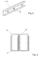
- eine Detailansicht eines C-förmigen Trägers, der für den Tragrahmen, die Stützen und den oberen Rahmen einsetzbar ist, und
- Fig. 4
- eine aufgebrochene Ansicht eines Standfußes mit zwei ineinander greifenden Teilen und einer Stellschraube.
- Fig. 1
- a diagram of a device according to the invention with a support frame, four supports and an upper frame,
- Fig. 2
- a diagram of the same device with attached parts of a packaging machine,
- Fig. 3
- a detail view of a C-shaped support, which is used for the support frame, the supports and the upper frame, and
- Fig. 4
- a broken view of a base with two interlocking parts and a set screw.
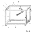
Mit 1 ist in
Das Gestell 1 bildet eine Raumeinheit für eine Verpackungsmaschine. Andere Maschinenaufbauten sind denkbar.The
Es können mehrere Gestelle 1 miteinander verbunden werden, um eine größere Raumeinheit zu bilden.
Die Profile 2 und 5 können identisch sein.The
Im vorliegenden Ausführungsbeispiel sind sowohl für die Profile 2 als auch die Profile 5 C-förmige Profile vorgesehen, die sich jedoch in diesem Fall etwas unterscheiden.In the present embodiment, 5 C-shaped profiles are provided both for the
Die Stützen 4 sind hohl ausgeführt. Im Bereich der Profile 2 und 5 sind in den Stützen 4 Öffnungen vorgesehen, die jedoch durch die Profile abgedeckt werden.The
Die Öffnung der C-förmigen Profile ist nach innen gerichtet.The opening of the C-shaped profiles is directed inwards.
In den Profilen 2 und 5 sind Versorgungs- und Steuerleitungen angeordnet. Hierzu sind im Profil Halter 8 angebracht, auf welchen die Leitungen getrennt voneinander oder in Bündeln aufgelegt werden. Auf diese Art und Weise kann man nicht nur die Leitungen sauber verlegen, sondern es werden auch gegenseitige Störeinflüsse vermieden. Es sind dabei auch Tragschienen oder dergleichen denkbar. Wichtig ist, daß die Leitungen geführt sind und an den Haltern 8 befestigt werden können.In the
Die gesamte Verlegung der Versorgungs- und Steuerleitungen erfolgt dabei weitgehend unsichtbar, da diese vollständig in den Profilen und Stützen verborgen sind und erst, wo es nicht mehr anders möglich ist, zu Tage treten.The entire laying of the supply and control lines is largely invisible, since they are completely hidden in the profiles and supports and only, where it is no longer possible, come to light.
Auch in den Stützen 4 können Führungen oder dergleichen für die Leitungen vorgesehen sein. Beim Übergang von den Profilen zu den Stützen 4 verlaufen die Leitungen durch die oben angesprochenen Öffnungen.Also in the
Zwischen den Stützen 4 können Wandelemente 9 vorgesehen sein, die im vorliegenden Ausfühnmgsbeispiel als Sicherheitsglasscheiben ausgebildet sind. Diese Wandelemente 9 verhindern einen unbeabsichtigten Zugriff von Personen in den Maschinenraum. Verletzungen und Betriebsstörungen werden so vermieden.Between the
Für Servicezwecke ist in der Regel ein Zugang zum Maschinenraum notwendig. Hierfür ist zwischen zwei benachbarten Stützen 4 ein Wandelement als Türe 10 ausgeführt. Diese Türe 10 wird durch einen Sicherheitsschalter gegen unerwünschtes Öffnen überwacht.For service purposes, access to the engine room is usually necessary. For this purpose, a wall element is designed as a
Zusätzlich lassen sich auch Zwischenstreben, Zwischenböden und dergleichen an den Stützen 4, aber auch an den Profilen 2 und 5 befestigen.In addition, intermediate struts, intermediate floors and the like can be attached to the
So lassen sich nahezu beliebige Befestigungsmöglichkeiten für Teile der Verpackungsmaschine schaffen. So ist es denkbar, daß am oberen Rahmen 6 bzw. an den diesen bildenden Profilen 5 ein Roboterarm befestigt ist, der für das Handling der Verpackungen zuständig ist. Auch alle anderen Bearbeitungsstationen können an der jeweils erforderlichen Stelle angeordnet werden.Thus, almost any attachment options for parts of the packaging machine can be created. Thus, it is conceivable that a robot arm is attached to the
Das die Vorrichtung bildende Gestell 1 ist so universell für verschiedenste Maschinen einsetzbar. Alle Maschinen haben aber dennoch ein einheitliches Erscheinungsbild.The frame forming the
An den Stützen 4 kann an der Außenseite auch ein Bedientableau 11 angebracht werden. Dies kann sich aber auch zwischen zwei Stützen erstrecken oder völlig separat angeordnet werden.On the
Im Bereich ders Tragrahmens 3 kann eine Steuereinheit für die Verpackungsmaschine angeordnet werden. Bei aufwendigeren Steuereinheiten ist diese auch auslagerbar und kann beispielsweise in einem extra Gestell vorgesehen werden. Dabei ist es denkbar, daß eine Steuereinheit für mehrere Maschinen genutzt werden kann.In the area of the
Zwischen den einzelnen Gestellen 1 kann ein Datenbus vorgesehen werden, so daß diese sehr einfach aneinander ankoppelbar sind. Das bedeutet auch, daß im Servicefall, wenn eine Vorrichtung ausgetauscht werden muss, diese sehr leicht entfernt und durch eine andere ersetzt werden kann. Der Betrieb der Maschine kann schnellstens fortgesetzt werden.Between the
Der Tragrahmen 3 ruht auf Füßen 7.The
Diese sind im vorliegenden Ausführungsbeispiel zweiteilig ausgebildet und aus einem Außenfuß 71 und einem Innenfuß 72 aufgebaut. Der Innenfuß 72 ist innerhalb der Außenfußes 71 angeordnet und ruht auf dem Untergrund. Der Außenfuß 71 dagegen ist am Tragrahmen 3 befestigt. Die beiden Teile sind über eine Einstellschraube 73 miteinander verbunden, die beispielsweise durch den Tragrahmen 3 hindurch erreichbar und bedienbar ist.These are formed in two parts in the present embodiment and constructed of an
Durch die Einstellschraube 73 lassen sich Innenfuß 72 und Außenfuß 71 gegeneinander verstellen wodurch das Gestell 1 ausnivelliert werden kann.By adjusting
Durch das Ineinandergreifen der Fußteile sind diese unanfällig für Verschmutzungen. Ablageflächen, auf denen sich Schmutz, vor allem Staub durch den Betrieb der Verpackungsmaschinen abzulagern vermag sind damit gegenüber herkömmlichen Einstellfüßen beseitigt.By interlocking the foot parts they are not susceptible to contamination. Deposits on which dirt, especially dust can deposit by the operation of the packaging machines are thus eliminated over conventional adjustment feet.
Die gesamten Gestelle 1 sind weitgehend glatt und leicht reinigbar ausgeführt.The
Die Öffnungen der C-Profile lassen sich auch noch durch zusätzliche Blenden abdecken, so daß nicht nur die darin verlaufenden Leitungen geschützt sind, sondern auch eine Schmutzablagerung verhindert wird.The openings of the C-profiles can also be covered by additional panels, so that not only the lines running therein are protected, but also a dirt deposit is prevented.
Claims (16)
Applications Claiming Priority (1)
| Application Number | Priority Date | Filing Date | Title |
|---|---|---|---|
| DE102014106333.3A DE102014106333B4 (en) | 2014-05-07 | 2014-05-07 | contraption |
Publications (1)
| Publication Number | Publication Date |
|---|---|
| EP2942301A1 true EP2942301A1 (en) | 2015-11-11 |
Family
ID=53365716
Family Applications (1)
| Application Number | Title | Priority Date | Filing Date |
|---|---|---|---|
| EP15166665.8A Withdrawn EP2942301A1 (en) | 2014-05-07 | 2015-05-06 | Device for machines construction |
Country Status (2)
| Country | Link |
|---|---|
| EP (1) | EP2942301A1 (en) |
| DE (1) | DE102014106333B4 (en) |
Cited By (4)
| Publication number | Priority date | Publication date | Assignee | Title |
|---|---|---|---|---|
| CN107128554A (en) * | 2017-04-28 | 2017-09-05 | 句容春天包装有限公司 | A kind of frame assembly on automatic packaging machine |
| DE102017122703A1 (en) * | 2017-08-21 | 2019-02-21 | Weber Maschinenbau Gmbh Breidenbach | Device for loading products |
| CN111043452A (en) * | 2019-11-29 | 2020-04-21 | 浙江省疏浚工程有限公司 | Base of filter press |
| EP4116201A1 (en) * | 2021-07-05 | 2023-01-11 | Weber Maschinenbau GmbH Breidenbach | Packaging machine |
Citations (7)
| Publication number | Priority date | Publication date | Assignee | Title |
|---|---|---|---|---|
| US4610561A (en) * | 1984-12-31 | 1986-09-09 | Italtel Tecnomeccanica S.P.A. | Sectional structure for carpentry, particularly to realize cubicles |
| US5848500A (en) * | 1997-01-07 | 1998-12-15 | Eastman Kodak Company | Light-tight enclosure and joint connectors for enclosure framework |
| WO2002051706A1 (en) * | 2000-12-22 | 2002-07-04 | Aautomag S.R.L. | Modular system made of steel structural work for a packaging line |
| DE10147361A1 (en) * | 2001-09-26 | 2003-04-24 | Schubert Gerhard Gmbh | Construction method of goods packing facility has rectangular hollow beams and columns containing all electrical, hydraulic and pneumatic services |
| US20060090419A1 (en) * | 2004-11-02 | 2006-05-04 | Chrisman Kenneth P | Modular infeeds for automatic forms/fill/seal equipment |
| WO2009058928A1 (en) * | 2007-10-30 | 2009-05-07 | The Siemon Company | Vertical patching system |
| WO2010064125A2 (en) * | 2008-12-03 | 2010-06-10 | Soremartec S.A. | Plant for packaging confectionary products in a sterile manner |
Family Cites Families (2)
| Publication number | Priority date | Publication date | Assignee | Title |
|---|---|---|---|---|
| DE7143956U (en) * | 1972-02-24 | Sarek As | Vibration-dampening, height-adjustable base | |
| EP2105649B1 (en) * | 2008-03-28 | 2013-01-30 | Neuman & Esser Deutschland GmbH & Co. KG | Machine framework |
-
2014
- 2014-05-07 DE DE102014106333.3A patent/DE102014106333B4/en active Active
-
2015
- 2015-05-06 EP EP15166665.8A patent/EP2942301A1/en not_active Withdrawn
Patent Citations (7)
| Publication number | Priority date | Publication date | Assignee | Title |
|---|---|---|---|---|
| US4610561A (en) * | 1984-12-31 | 1986-09-09 | Italtel Tecnomeccanica S.P.A. | Sectional structure for carpentry, particularly to realize cubicles |
| US5848500A (en) * | 1997-01-07 | 1998-12-15 | Eastman Kodak Company | Light-tight enclosure and joint connectors for enclosure framework |
| WO2002051706A1 (en) * | 2000-12-22 | 2002-07-04 | Aautomag S.R.L. | Modular system made of steel structural work for a packaging line |
| DE10147361A1 (en) * | 2001-09-26 | 2003-04-24 | Schubert Gerhard Gmbh | Construction method of goods packing facility has rectangular hollow beams and columns containing all electrical, hydraulic and pneumatic services |
| US20060090419A1 (en) * | 2004-11-02 | 2006-05-04 | Chrisman Kenneth P | Modular infeeds for automatic forms/fill/seal equipment |
| WO2009058928A1 (en) * | 2007-10-30 | 2009-05-07 | The Siemon Company | Vertical patching system |
| WO2010064125A2 (en) * | 2008-12-03 | 2010-06-10 | Soremartec S.A. | Plant for packaging confectionary products in a sterile manner |
Cited By (5)
| Publication number | Priority date | Publication date | Assignee | Title |
|---|---|---|---|---|
| CN107128554A (en) * | 2017-04-28 | 2017-09-05 | 句容春天包装有限公司 | A kind of frame assembly on automatic packaging machine |
| DE102017122703A1 (en) * | 2017-08-21 | 2019-02-21 | Weber Maschinenbau Gmbh Breidenbach | Device for loading products |
| CN111043452A (en) * | 2019-11-29 | 2020-04-21 | 浙江省疏浚工程有限公司 | Base of filter press |
| CN111043452B (en) * | 2019-11-29 | 2021-05-18 | 浙江省疏浚工程有限公司 | Base of filter press |
| EP4116201A1 (en) * | 2021-07-05 | 2023-01-11 | Weber Maschinenbau GmbH Breidenbach | Packaging machine |
Also Published As
| Publication number | Publication date |
|---|---|
| DE102014106333B4 (en) | 2023-02-16 |
| DE102014106333A1 (en) | 2015-11-12 |
Similar Documents
| Publication | Publication Date | Title |
|---|---|---|
| EP2124302B1 (en) | Frame for a test cell | |
| EP2942301A1 (en) | Device for machines construction | |
| EP2160253B1 (en) | Coating zone with inclined guide rails | |
| DE7006464U (en) | ENVIRONMENTAL CONTROL UNIT FOR ANIMALS | |
| EP1749584B1 (en) | Spray booth and installation having overhead tools | |
| EP2101926B1 (en) | Coating system and method for the series coating of workpieces | |
| DE202019106362U1 (en) | Foldable multi-storey box with flexible inserts for goods transport | |
| DE102010005446A1 (en) | Device for e.g. milling elongated work pieces, has support plate adjustable in guide rails along longitudinal axes by programmable drive using rotating movement of movable adjustment device, and robot secured on support plate | |
| EP1330409A1 (en) | Machine protection device | |
| EP3256305B1 (en) | Protection cover for an injection moulding machine | |
| DE3321195C2 (en) | ||
| AT517903A1 (en) | EQUIPMENT FOR MACHINING HOUSEFACES | |
| EP3560050A1 (en) | Machine frame having a switch cabinet | |
| DE10348246B3 (en) | Cooling arrangement, especially for goods in food counters, with hinged goods support has evaporator and support joined to trough by respective rotary joints with rotation axes in same direction | |
| EP0733321B1 (en) | Holding device for a tray to be fixed underneath a table or the like | |
| WO2000016017A1 (en) | Method and device for protecting persons and/or products from air-borne particles | |
| DE3812798C1 (en) | ||
| DE19703835C2 (en) | Guidance for self-service markets or the like | |
| DE202013101377U1 (en) | Protective structure for securing a machine or a system | |
| EP3697722B1 (en) | Housing for an industrial installation | |
| AT512816B1 (en) | Safety device for an injection molding machine | |
| EP3623632B1 (en) | Modular frame system for vacuum pumps | |
| DE19739863C2 (en) | Hood | |
| EP3666406B1 (en) | Washing machine | |
| EP3300649B1 (en) | Load platform for a cleaning appliance |
Legal Events
| Date | Code | Title | Description |
|---|---|---|---|
| PUAI | Public reference made under article 153(3) epc to a published international application that has entered the european phase |
Free format text: ORIGINAL CODE: 0009012 |
|
| AK | Designated contracting states |
Kind code of ref document: A1 Designated state(s): AL AT BE BG CH CY CZ DE DK EE ES FI FR GB GR HR HU IE IS IT LI LT LU LV MC MK MT NL NO PL PT RO RS SE SI SK SM TR |
|
| AX | Request for extension of the european patent |
Extension state: BA ME |
|
| 17P | Request for examination filed |
Effective date: 20151222 |
|
| RAX | Requested extension states of the european patent have changed |
Extension state: BA Payment date: 20151222 Extension state: ME Payment date: 20151222 |
|
| RBV | Designated contracting states (corrected) |
Designated state(s): AL AT BE BG CH CY CZ DE DK EE ES FI FR GB GR HR HU IE IS IT LI LT LU LV MC MK MT NL NO PL PT RO RS SE SI SK SM TR |
|
| 17Q | First examination report despatched |
Effective date: 20171026 |
|
| STAA | Information on the status of an ep patent application or granted ep patent |
Free format text: STATUS: THE APPLICATION IS DEEMED TO BE WITHDRAWN |
|
| 18D | Application deemed to be withdrawn |
Effective date: 20180919 |