EP2944280A1 - High frequency electrosurgical operation instrument and high frequency electrosurgical operation system - Google Patents
High frequency electrosurgical operation instrument and high frequency electrosurgical operation system Download PDFInfo
- Publication number
- EP2944280A1 EP2944280A1 EP13870674.2A EP13870674A EP2944280A1 EP 2944280 A1 EP2944280 A1 EP 2944280A1 EP 13870674 A EP13870674 A EP 13870674A EP 2944280 A1 EP2944280 A1 EP 2944280A1
- Authority
- EP
- European Patent Office
- Prior art keywords
- forceps pieces
- forceps
- distal end
- liquid
- manipulation rod
- Prior art date
- Legal status (The legal status is an assumption and is not a legal conclusion. Google has not performed a legal analysis and makes no representation as to the accuracy of the status listed.)
- Pending
Links
Images


Classifications
-
- A—HUMAN NECESSITIES
- A61—MEDICAL OR VETERINARY SCIENCE; HYGIENE
- A61B—DIAGNOSIS; SURGERY; IDENTIFICATION
- A61B18/00—Surgical instruments, devices or methods for transferring non-mechanical forms of energy to or from the body
- A61B18/04—Surgical instruments, devices or methods for transferring non-mechanical forms of energy to or from the body by heating
- A61B18/12—Surgical instruments, devices or methods for transferring non-mechanical forms of energy to or from the body by heating by passing a current through the tissue to be heated, e.g. high-frequency current
- A61B18/14—Probes or electrodes therefor
- A61B18/1442—Probes having pivoting end effectors, e.g. forceps
- A61B18/1445—Probes having pivoting end effectors, e.g. forceps at the distal end of a shaft, e.g. forceps or scissors at the end of a rigid rod
-
- A—HUMAN NECESSITIES
- A61—MEDICAL OR VETERINARY SCIENCE; HYGIENE
- A61B—DIAGNOSIS; SURGERY; IDENTIFICATION
- A61B18/00—Surgical instruments, devices or methods for transferring non-mechanical forms of energy to or from the body
- A61B18/04—Surgical instruments, devices or methods for transferring non-mechanical forms of energy to or from the body by heating
- A61B18/12—Surgical instruments, devices or methods for transferring non-mechanical forms of energy to or from the body by heating by passing a current through the tissue to be heated, e.g. high-frequency current
- A61B18/1206—Generators therefor
-
- A—HUMAN NECESSITIES
- A61—MEDICAL OR VETERINARY SCIENCE; HYGIENE
- A61B—DIAGNOSIS; SURGERY; IDENTIFICATION
- A61B17/00—Surgical instruments, devices or methods, e.g. tourniquets
- A61B17/28—Surgical forceps
- A61B17/2812—Surgical forceps with a single pivotal connection
- A61B17/282—Jaws
- A61B2017/2825—Inserts of different material in jaws
-
- A—HUMAN NECESSITIES
- A61—MEDICAL OR VETERINARY SCIENCE; HYGIENE
- A61B—DIAGNOSIS; SURGERY; IDENTIFICATION
- A61B18/00—Surgical instruments, devices or methods for transferring non-mechanical forms of energy to or from the body
- A61B2018/00571—Surgical instruments, devices or methods for transferring non-mechanical forms of energy to or from the body for achieving a particular surgical effect
- A61B2018/00589—Coagulation
-
- A—HUMAN NECESSITIES
- A61—MEDICAL OR VETERINARY SCIENCE; HYGIENE
- A61B—DIAGNOSIS; SURGERY; IDENTIFICATION
- A61B18/00—Surgical instruments, devices or methods for transferring non-mechanical forms of energy to or from the body
- A61B18/04—Surgical instruments, devices or methods for transferring non-mechanical forms of energy to or from the body by heating
- A61B18/12—Surgical instruments, devices or methods for transferring non-mechanical forms of energy to or from the body by heating by passing a current through the tissue to be heated, e.g. high-frequency current
- A61B18/1206—Generators therefor
- A61B2018/1246—Generators therefor characterised by the output polarity
- A61B2018/126—Generators therefor characterised by the output polarity bipolar
-
- A—HUMAN NECESSITIES
- A61—MEDICAL OR VETERINARY SCIENCE; HYGIENE
- A61B—DIAGNOSIS; SURGERY; IDENTIFICATION
- A61B2218/00—Details of surgical instruments, devices or methods for transferring non-mechanical forms of energy to or from the body
- A61B2218/001—Details of surgical instruments, devices or methods for transferring non-mechanical forms of energy to or from the body having means for irrigation and/or aspiration of substances to and/or from the surgical site
- A61B2218/002—Irrigation
Abstract
Description
- The present invention relates to a high-frequency electrosurgical treatment instrument for operations and a high-frequency electrosurgical system for operations, in which liquid is conveyed to an affected area.
- In general surgical operations and endoscopic treatment, affected areas often bleed. To stop the bleeding, electrocoagulation with supply of a liquid is effective.
- Patent Literature 1, for example, discloses operation equipment for treating tissue. This operation equipment is a monopolar high-frequency electrical treatment instrument for the abdominal cavity, and is capable of coagulation by high-frequency power while supplying liquid to an affected area.
- Patent Literature 2, for example, discloses a high-frequency forceps for laparotomy. This high-frequency forceps is bipolar.
- Patent Literature 3, for example, discloses a beak-shaped treatment instrument for an endoscope, which treats an affected area as a source of bleeding immediately after washing off the blood and other substances.
-
Patent Literature 4, for example, discloses a high-frequency treatment instrument for an endoscope, in which a nozzle pipe and a water conveyance tube are not disconnected from each other even when the water conveyance operation is performed with the nozzle pipe closed. - Patent Literature 5, for example, discloses a treatment instrument for an endoscope, which is capable of identifying a bleeding site quickly and reliably and providing necessary treatment promptly and reliably.
-
- Patent Literature 1 : Jpn. PCT National Publication No.
2005-502424 - Patent Literature 2 :
U.S. Patent No. 4,567,890 - Patent Literature 3 : Jpn. Pat. Appln. KOKAI Publication No.
2004-275548 - Patent Literature 4 : Jpn. Pat. Appln. KOKAI Publication No.
2007-20969 - Patent Literature 5 : Jpn. Pat. Appln. KOKAI Publication No.
2005-224426 - In Patent Literature 1 described above, the high-frequency treatment instrument is monopolar. In the high-frequency treatment instrument, therefore, invasion of an affected area in a depth direction is large, and the affected area is not treated easily. The high-frequency treatment instrument is not shaped like a forceps and thus cannot grip tissue.
- In Patent Literature 2, the high-frequency forceps is bipolar. An invasion of an affected area in a depth direction is therefore small. The high-frequency forceps, however, is for laparotomy and is not suitable for the abdominal cavity.
- In Patent Literature 3 and
Patent Literature 4, the water conveyance tube is arranged on the center axis of the beak-shaped treatment instrument. Because of this, the manipulation wire for opening/closing the forceps interferes with the water conveyance tube, thus the force for opening/closing the forceps is impaired. Since the cross-sectional area of the manipulation wire is limited by the cross-sectional area of the water conveyance tube, the strength of the manipulation wire is reduced. This structure is not suitable for laparoscopic surgery because a forceps grips and strips an organ or a resected piece of a few hundred grams of tissue in laparoscopic surgery. - In Patent Literature 5, an opening through portion which liquid is dripped is disposed at a distance from the forceps. Such a structure is suitable for identifying the bleeding site quickly and reliably through water conveyance. This structure, however, is not suitable for high frequency heating of the conveyed liquid and treating the tissue near the forceps in this state. Moreover, it is difficult to heat the tissue near the forceps because the forceps and the opening portion are separated from each other.
- The present invention therefore aims to provide a bipolar high-frequency electrosurgical treatment instrument for operations and a high-frequency electrosurgical system for operations, which are for use in the abdominal cavity and treat an affected area easily by conveying liquid to the affected area, with a small invasion.
- An aspect of a high-frequency electrosurgical treatment instrument for operations of the present invention includes a pair of forceps pieces including grip surfaces opposed to each other to grip an affected area, the forceps pieces being capable of being opened and closed relative to each other; an insulating member disposed at proximal end portions of the forceps pieces and insulates one of the forceps pieces from the other forceps piece; a transmission member coupled to one of the forceps pieces such that one of the forceps pieces and the other forceps pieces are pivotably coupled to each other; a manipulation rod member including a distal end portion and a proximal end portion, the distal end portion being fixed to the transmission member; a distal end cover member including a fulcrum that pivotably couples one of the pair of forceps pieces; a shaft member into which the manipulation rod member is inserted to cover the manipulation rod member so as to wrap the manipulation rod member from the distal end portion to the proximal end portion, the shaft member being inserted into a body cavity together with the manipulation rod member; a manipulation portion including a movable handle removably coupled to the proximal end portion of the manipulation rod member and a fixed handle removably coupled to a proximal end of the shaft member; a flow channel portion formed between the manipulation rod member and the shaft member in a radial direction of the shaft member, the flow channel portion being disposed along a longitudinal direction of the manipulation rod member, when the manipulation rod member is inserted into the shaft member, to allow liquid to flow; a groove portion that communicates with the flow channel portion and is disposed along the longitudinal direction of the manipulation rod member on an outer peripheral surface of the distal end cover member to allow the liquid to flow from the flow channel portion; and an opening portion that communicates with the groove portion to supply the liquid near the proximal end portions of the pair of forceps pieces.
- An aspect of a high-frequency electrosurgical system for operations of the present invention includes a pair of forceps pieces including grip surfaces opposed to each other to grip an affected area, the forceps pieces being capable of being opened and closed relative to each other; an insulating member disposed at proximal end portions of the forceps pieces and insulates one of the forceps pieces from the other forceps piece; a transmission member coupled to one of the forceps pieces such that one of the forceps pieces and the other forceps pieces are pivotably coupled to each other; a manipulation rod member including a distal end portion and a proximal end portion, the distal end portion being fixed to the transmission member; a distal end cover member including a fulcrum that pivotably couples with one of the forceps pieces; a shaft member into which the manipulation rod member is inserted to cover the manipulation rod member so as to wrap the manipulation rod member from the distal end portion to the proximal end portion, the shaft member being inserted into a body cavity together with the manipulation rod member; a manipulation portion including a movable handle removably coupled to the proximal end portion of the manipulation rod member and a fixed handle removably coupled to a proximal end portion of the shaft member; a flow channel portion formed between the manipulation rod member and the shaft member in a radial direction of the shaft member, the flow channel portion being disposed along a longitudinal direction of the manipulation rod member, when the manipulation rod member is inserted into the shaft member, to allow liquid to flow; a groove portion that communicates with the flow channel portion and is disposed along the longitudinal direction of the manipulation rod member on an outer peripheral surface of the distal end cover member to allow the liquid to flow from the flow channel portion; an opening portion that communicates with the groove portion to supply the liquid near the proximal end portions of the pair of forceps pieces; a connector including a return electrode that electrically conducts with one of the forceps pieces and an active electrode that electrically conducts with the other forceps piece; a liquid conveyance unit that conveys the liquid toward the flow channel portion; and a power supply electrically connected with the connector to supply power to the forceps pieces.
- The present invention provides a bipolar high-frequency electrosurgical treatment instrument for operations and a high-frequency electrosurgical system for operations, which are for use in the abdominal cavity and treat an affected area easily by conveying liquid to the affected area, with a small invasion.
-
-
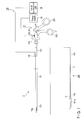
FIG. 1 is a schematic diagram of a treatment system in a first embodiment according to the present invention. -
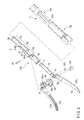
FIG. 2 is an exploded perspective view of the vicinity of a distal end portion of a shaft member. -
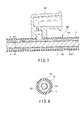
FIG. 3 is a diagram showing the internal structure of a manipulation rod member and the shaft member in the vicinity of an inlet port portion. -
FIG. 4 is a cross-sectional view along a line 4-4 inFIG. 3 . -
FIG. 5 is a perspective view of the vicinity of the distal end portion of the shaft member. -
FIG. 6 shows a state in which the manipulation rod member is taken out of the shaft member in a state shown inFIG. 5 . -
FIG. 7 is a diagram showing an engagement and fixing part between a distal end cover member and the shaft member, without showing a sheath member and a groove cover member. -
FIG. 8 is a diagram showing a channel through which liquid flows in the vicinity of an insulating member. -
FIG. 9 is a diagram showing a channel through which liquid flows in the vicinity of an insulating member in a second embodiment. -
FIG. 10 is a diagram showing a communicative state of through hole portions with forceps pieces closed. -
FIG. 11 is a diagram showing a communicative state of the through hole portions with the forceps pieces opened. -
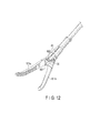
FIG. 12 is a perspective view of the vicinity of a distal end portion of a forceps unit only with a groove and without a through hole portion. -
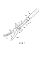
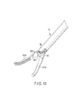
FIG. 13 is a perspective view of the vicinity of a distal end portion of a treatment instrument only with a groove and without a through hole portion. -
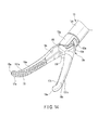
FIG. 14 is a perspective view of the vicinity of a distal end portion of a shaft member with a grip groove portion disposed at a grip surface according to a first modification. -
FIG. 15 is a front view of forceps pieces shown inFIG. 14 . -
FIG. 16 is a perspective view of the vicinity of a distal end portion of a shaft member with insulating grip members disposed according to a second modification. -
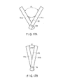
FIG. 17A is a diagram showing a relationship between an opening angle between forceps pieces and a wet area of the forceps pieces wet with a liquid. -
FIG. 17B is a diagram showing a relationship between an opening angle between forceps pieces and a wet area of the forceps pieces wet with a liquid. -
FIG. 17C is a diagram showing a relationship between an opening angle between forceps pieces and a wet area of the forceps pieces wet with a liquid. -
FIG. 17D is a diagram showing a relationship between an opening angle between forceps pieces and a wet area of the forceps pieces wet with a liquid. -
FIG. 18 is a perspective view of the vicinity of a distal end portion of a shaft member, with removable insulating grip members. -
FIG. 19 is a perspective view of the vicinity of a distal end portion of a forceps unit with an open window portion disposed in a grip surface according to a third modification. - Embodiments of the present invention will be described in detail below with reference to the drawings.
- Referring to
FIG. 1 ,FIG. 2 ,FIG. 3, FIG. 4 ,FIG. 5 ,FIG. 6 ,FIG. 7 , andFIG. 8 , a first embodiment will be described. In some of the drawings, some members are not shown for clarification of the drawings. - As shown in
FIG. 1 , atreatment system 100 comprises a treatment instrument 1, apower supply 33, and aliquid conveyance unit 35. - The treatment instrument 1 as shown in
FIG. 1 is, for example, a bipolar electrical treatment instrument for use in surgical operations, which is a high-frequency electrosurgical treatment instrument for operations. Examples of the surgical operations (the applications of the treatment instrument 1) mainly include liver resection, kidney resection, and pancreas resection under a laparoscope. In the surgical operations as described above, the treatment instrument 1 is used, for example, for stripping, gripping, resection, and sampling of living tissue, and electrocoagulation and astriction for bleeding. In the main applications, that is, in resection of parenchymal organs such as the liver, kidneys, and pancreas, oozing bleeding is likely to occur, in which the resected surface bleeds uniformly. Electrocoagulation with supply of liquid is effective for such bleeding. This allows the bleeding resected surface to be coagulated uniformly. Moreover, excessive coagulation is prevented and heat damage to living tissue is minimized because the living tissue is heated to temperatures not higher than the boiling point of the liquid. - As shown in
FIG. 1 andFIG. 2 , the treatment instrument 1 comprises aforceps unit 300 including a pair offorceps pieces manipulation rod member 11, and ashaft member 13 into which themanipulation rod member 11 is inserted so that theshaft member 13 covers (externally covers) themanipulation rod member 11 so as to wrap themanipulation rod member 11 from adistal end portion 11a of themanipulation rod member 11 to aproximal end portion 11b of themanipulation rod member 11 and is inserted into the body cavity together with themanipulation rod member 11. The treatment instrument 1 further comprises amanipulation portion 31 including amovable handle 201 removably coupled to theproximal end portion 11b of themanipulation rod member 11 and a fixedhandle 202 removably coupled to aproximal end portion 13b of theshaft member 13, themovable handle 201 is opened/closed relative to the fixedhandle 202 thereby opening/closing theforceps pieces - As shown in
FIG. 1 andFIG. 2 , theforceps unit 300 includes the pair offorceps pieces member 55, atransmission member 51, the elongatedmanipulation rod member 11 having asheath member 11d, an insulatingtubular member 53, a distalend cover member 12, afulcrum pin member 501, anaction pin member 15d, and anaction pin member 502. - The pair of
forceps pieces grip surfaces forceps pieces forceps pieces - The insulating
member 55 is disposed at the proximal end portions of theforceps pieces forceps piece 151a from theother forceps piece 151b. The insulatingmember 55 is fitted in a proximalend opening portion 152a provided at the proximal end portion of theforceps piece 151a. The insulatingmember 55 is pivotably coupled together with theforceps piece 151a to aproximal end portion 15b of theforceps piece 151b via theaction pin member 15d. That is, theaction pin member 15d couples the insulatingmember 55, theforceps piece 151a, and theforceps piece 151b together. The insulatingmember 55 has anopening portion 55f. The proximal end portion of theopening portion 55f is fitted in part of theproximal end portion 15b of theforceps piece 151b. - The
transmission member 51 couples with one of theforceps piece 151a and theforceps piece 151b such that theforceps piece 151a and theforceps piece 151b are pivotably coupled with each other. Thetransmission member 51 is coupled with theproximal end portion 15b of theforceps piece 151b, for example, via theaction pin member 502. - As shown in
FIG. 1 , themanipulation rod member 11 has thedistal end portion 11a and theproximal end portion 11b. As shown inFIG. 8 andFIG. 9 , thedistal end portion 11a is fixed to thetransmission member 51. Thetransmission member 51 and themanipulation rod member 11 are fixed by screw fastening, brazing, thermal fitting, or any other means. - The
manipulation rod member 11 is, for example, a metal cylindrical member. As shown inFIG. 3 and FIG. 4 , themanipulation rod member 11 has thesheath member 11d that sheathes themanipulation rod member 11. Thesheath member 11d is an insulating member that insulates themanipulation rod member 11. Such asheath member 11d functions as an insulating coating such as PTFE. - As shown in
FIG. 2 , the distalend cover member 12 has a bifurcateddistal end portion 12a, alarge diameter portion 12b having the shape of a hollow cylinder, and asmall diameter portion 12c. Thesmall diameter portion 12c is disposed at the proximal end portion of the distalend cover member 12. Thelarge diameter portion 12b is sandwiched between thedistal end portion 12a and thesmall diameter portion 12c in the axial direction of the distalend cover member 12. Thedistal end portion 12a is integral with thelarge diameter portion 12b, and thelarge diameter portion 12b is integral with thesmall diameter portion 12c. - The
small diameter portion 12c hasprojection portions 12e disposed at the proximal end portion of thesmall diameter portion 12c. Theprojection portions 12e are removably engaged withengagement cuts 313 of theshaft member 13 described later, whereby theshaft member 13 and the distalend cover member 12 are removably fixed. - The
distal end portion 12a accommodates the proximalend opening portion 152a of theforceps piece 151a, the insulatingmember 55, and theproximal end portion 15b of theforceps piece 151b. Thedistal end portion 12a has thefulcrum pin member 501 that functions as the fulcrum of pivot. Thedistal end portion 12a is coupled with theforceps piece 151a and the insulatingmember 55 via thefulcrum pin member 501, for example, such that theforceps piece 151a and the insulatingmember 55 pivot relative to thedistal end portion 12a with thefulcrum pin member 501 as a fulcrum. - As described above, the distal
end cover member 12 has thefulcrum pin member 501 that functions as a fulcrum for pivotably coupling, for example, theforceps piece 151a to thedistal end portion 12a. - The insulating
tubular member 53 having the shape of a hollow cylinder is fixed in the interior of thelarge diameter portion 12b of the distalend cover member 12. In other words, thelarge diameter portion 12b can accommodate the insulatingtubular member 53, and the accommodatinglarge diameter portion 12b can be removably fixed to the insulatingtubular member 53. The fixing is thermal fitting or adhesion, or both. The inner diameter of the insulatingtubular member 53 and the inner diameter of thesmall diameter portion 12c have such a size that allows insertion and removal of thetransmission member 51 and themanipulation rod member 11. - As shown in
FIG. 3 and FIG. 4 , theshaft member 13 has a cylindrical shape such that themanipulation rod member 11 is inserted into theshaft member 13 and that theshaft member 13 covers themanipulation rod member 11. Here, as shown inFIG. 3 and FIG. 4 , the inner diameter of theshaft member 13 is larger than the outer diameter of themanipulation rod member 11 including thesheath member 11d. Accordingly, when themanipulation rod member 11 is inserted into theshaft member 13, aflow channel portion 43 functioning as a space portion is formed between themanipulation rod member 11 and theshaft member 13 in the radial direction of theshaft member 13. Thisflow channel portion 43 represents the space portion between the exterior of themanipulation rod member 11 and the interior of theshaft member 13, in other words, between the outer peripheral surface of the manipulation rod member 11 (thesheath member 11d) and the inner peripheral surface of theshaft member 13. Theflow channel portion 43 is also covered with theshaft member 13. As shown inFIG. 3 , theflow channel portion 43 is disposed along the longitudinal direction of the shaft member 13 (the manipulation rod member 11). Such aflow channel portion 43 is included in a flow channel portion (liquid conveyance portion) 41 through which liquid flows, for example, from theproximal end portion 11b side toward thedistal end portion 11a side of themanipulation rod member 11 by means of theliquid conveyance unit 35. In theflow channel portion 43, liquid flows from the proximal end portion side toward the distal end portion side of theflow channel portion 43. - As described above, the
flow channel portion 43 is formed between themanipulation rod member 11 and theshaft member 13 in the radial direction of theshaft member 13 and is disposed along the longitudinal direction of themanipulation rod member 11 when themanipulation rod member 11 is inserted into theshaft member 13. In theflow channel portion 43, liquid flows from the proximal end portion side of theflow channel portion 43 toward the distal end portion side of theflow channel portion 43. - The
shaft member 13 contains, for example, a metal such as SUS. Such ashaft member 13 has asheath member 13d that sheathes theshaft member 13, as shown inFIG. 3 and FIG. 4 . Thesheath member 13d has an insulating material that insulates theshaft member 13. Such asheath member 13d has an insulating coating such as PTFE. - As shown in
FIG. 1 andFIG. 3 , theshaft member 13 has aninlet port portion 13f that is disposed on theproximal end portion 13b side of theshaft member 13 and through which liquid from theliquid conveyance unit 35 outside the treatment instrument 1 is fed to theflow channel portion 43. Theinlet port portion 13f is a supply port that is coupled with theliquid conveyance unit 35 and through which liquid from theliquid conveyance unit 35 is supplied to theflow channel portion 43. Theinlet port portion 13f passes through theshaft member 13 and thesheath member 13d and communicates with the flow channel portion 43 (the interior of the shaft member 13). The liquid supplied from theliquid conveyance unit 35 flows into theflow channel portion 43 through theinlet port portion 13f and is conveyed through from theflow channel portion 43 toward the distalend cover member 12. - As shown in
FIG. 5 andFIG. 6 , theshaft member 13 has agroove cover member 13g that coversgroove portions 45 described later so as to cap thegroove portions 45 when themanipulation rod member 11 is inserted into theshaft member 13. Thegroove cover member 13g is formed as a cylindrical member into which adistal end portion 13a of theshaft member 13 and the distalend cover member 12 are inserted. As described above, thegroove cover member 13g is disposed at thedistal end portion 13a side of theshaft member 13. Such agroove cover member 13g is included in theshaft member 13. The distal end portion of thegroove cover member 13g is exposed, and the proximal end portion of thegroove cover member 13g is covered by thesheath member 13d. When thedistal end portion 13a of theshaft member 13 and the distalend cover member 12 are inserted into thegroove cover member 13g, the proximal end portion of thegroove cover member 13g covers the engagement cuts 313 andproximal end portions 45b of thegroove portions 45. The distal end portion of thegroove cover member 13g is bifurcated into two. The distal end portions of thegroove cover member 13g are disposed so as to correspond to the arrangement position ofdistal end portions 45a of thegroove portions 45. The distal end portions of thegroove cover member 13g are therefore disposed 180° apart from each other in the circumferential direction in the longitudinal direction of the shaft member 13 (the manipulation rod member 11). When the distalend cover member 12 is inserted into thegroove cover member 13g, the distal end portions of thegroove cover member 13g cover thedistal end portions 45a of thegroove portions 45. Thegroove cover member 13g may be separated from thedistal end portion 13a as mentioned above or may be integral with thedistal end portion 13a. In the case where thegroove cover member 13g is integral with thedistal end portion 13a, thegroove cover member 13g is part of the bifurcateddistal end portion 13a. - As shown in
FIG. 2 , theshaft member 13 has twoengagement cuts 313 substantially in the shape of a L that are disposed at thedistal end portion 13a of theshaft member 13. The engagement cuts 313 are provided axially symmetric with each other.FIG. 7 shows the distal end portion of the treatment instrument 1 without showing thesheath member 13d and thegroove cover member 13g. As shown inFIG. 7 , theprojection portions 12e enter the engagement cuts 313, and theprojection portions 12e are engaged with the proximal end portions of the engagement cuts 313, whereby the distalend cover member 12 is fixed to theshaft member 13. Theshaft member 13 including the engagement cuts 313 contains a metal such as SUS as described above. Accordingly, theshaft member 13 is engaged with the distalend cover member 12 of a metal such as SUS so that electrical continuity is established between theshaft member 13 and the distalend cover member 12. - As shown in
FIG. 1 , when themanipulation rod member 11 is inserted into (put into) theshaft member 13 from theproximal end portion 11b of themanipulation rod member 11 toward thedistal end portion 13a of theshaft member 13, theproximal end portion 11b of themanipulation rod member 11 is fixed to themovable handle 201. Theshaft member 13 is thereby fixed to the fixedhandle 202. Here, since theprojection portions 12e are engaged with the engagement cuts 313, the distalend cover member 12 is fixed to the fixedhandle 202 via theshaft member 13, and themanipulation rod member 11 and thetransmission member 51 are fixed to themovable handle 201. When themovable handle 201 is closed relative to the fixedhandle 202, themanipulation rod member 11 is pulled toward themanipulation portion 31, and theforceps pieces manipulation rod member 11 is pushed toward theforceps pieces forceps pieces - The treatment instrument 1 in the present embodiment is a bipolar high-frequency electrical treatment instrument. The
forceps pieces end cover member 12, themanipulation rod member 11, thetransmission member 51, and theshaft member 13 including the engagement cuts 313 contain a metal such as SUS. The insulatingtubular member 53 fitted on the inner surface of thelarge diameter portion 12b, thesheath member 11d that sheathes themanipulation rod member 11 and thetransmission member 51, the insulatingmember 55, theaction pin member 15d, and theaction pin member 502 are formed of, for example, an insulating material such as PFA, PTFE, alumina, aluminium nitride, or zirconia. - As shown in
FIG. 1 , themanipulation portion 31 has aconnector portion 31a to be connected to thepower supply 33. Theconnector portion 31a has anactive electrode 31b and areturn electrode 31c. Theactive electrode 31b is in electrical conduction with themanipulation rod member 11, thetransmission member 51, and theforceps piece 151b. Thereturn electrode 31c is in electrical conduction with theshaft member 13, the distalend cover member 12, and theforceps piece 151a. The conducting path of theactive electrode 31b from themanipulation rod member 11 to theforceps piece 151b through thetransmission member 51 and the conducting path of thereturn electrode 31c from theforceps piece 151a to theshaft member 13 through the distalend cover member 12 are electrically insulated by thesheath member 11d, the insulatingtubular member 53, the insulatingmember 55, theaction pin member 15d, and theaction pin member 502. When high-frequency power is supplied from thepower supply 33 to theforceps pieces forceps piece 151a and theforceps piece 151b in contact with living tissue, liquid, and other substances, a high-frequency current flows from theforceps piece 151b toward the living tissue, and a high-frequency current flows from a medium such as the liquid toward theforceps piece 151a. The living tissue and the medium such as the liquid are heated by Joule heating because their electrical conductivity is lower than the electrical conductivity of the metal that is the material of the conducting path of theforceps pieces active electrode 31b and thereturn electrode 31c. - The
power supply 33 is electrically connected with theconnector portion 31a to supply power to theforceps pieces - As shown in
FIG. 1 , theliquid conveyance unit 35 is coupled to theinlet port portion 13f to convey liquid from theinlet port portion 13f to theflow channel portion 43 and supply the liquid from theopening portion 55f of the insulatingmember 55 toward an affected area. An example of the liquid in theliquid conveyance unit 35 is an isotonic solution having the same osmotic pressure as living tissue in human bodies. An example of the isotonic solution is physiological saline solution. - Referring now to
FIG. 6 andFIG. 8 , theflow channel portion 41 in the present embodiment which conveys liquid from theinlet port portion 13f toward theopening portion 55f provided in the insulatingmember 55 of theforceps pieces - The
flow channel portion 41 includes theinlet port portion 13f described above, theflow channel portion 43 described above, the engagement cuts 313 of theshaft member 13, thegroove portions 45 in communication with the engagement cuts 313 at theproximal end portions 45b of thegroove portions 45, throughhole portions 47 in communication with thegroove portions 45, throughhole portions 55d in communication with the throughhole portions 47, and theopening portion 55f described above in communication with the throughhole portions 55d. - As shown in
FIG. 3 , theflow channel portion 43 is formed between themanipulation rod member 11 and theshaft member 13 in the radial direction and is disposed along the longitudinal direction of the shaft member 13 (the manipulation rod member 11). - The
groove portion 45 communicates with theflow channel portion 43 and is disposed along the longitudinal direction of themanipulation rod member 11 on an outerperipheral surface 12d of the distalend cover member 12. Liquid flows into thegroove portion 45 from theflow channel portion 43. Thegroove portions 45 are disposed at both of the two bifurcateddistal end portions 12a of the distalend cover member 12. - As shown in
FIG. 2 , thegroove portion 45 is disposed from the throughhole portion 47 provided at the bifurcateddistal end portion 12a of the distalend cover member 12 to thelarge diameter portion 12b, along the longitudinal direction of the shaft member 13 (the manipulation rod member 11). Thedistal end portion 45a of thegroove portion 45 is formed in such a manner that the distalend cover member 12 is partially depressed. Thedistal end portion 45a functions as theflow channel portion 41. Theproximal end portion 45b of thegroove portion 45 is disposed at thelarge diameter portion 12b so as to pass through thelarge diameter portion 12 in the thickness direction of thelarge diameter portion 12. That is, theproximal end portion 45b functions as a through hole portion. As shown inFIG. 8 , the outer peripheral surface of the insulatingtubular member 53 inserted into thelarge diameter portion 12b functions as the bottom surface of theproximal end portion 45b. Theproximal end portion 45b and the outer peripheral surface of the insulatingtubular member 53 function as theflow channel portion 41. Such twogroove portions 45 are disposed symmetrically with respect to the center axis of themanipulation rod member 11. Thegroove portion 45 is disposed, for example, orthogonally to theforceps pieces groove portion 45 is therefore disposed, for example, orthogonally to the opening/closing direction of theforceps pieces FIG. 7 , when the distalend cover member 12 and theshaft member 13 are engaged with and fixed to each other, the opening direction of thegroove portion 45 on theproximal end portion 45b side generally agrees with the opening direction of the engagement cut 313 of theshaft member 13. As shown inFIG. 5 , thegroove portion 45 is covered (capped) with thegroove cover member 13g. - As shown in
FIG. 8 , thedistal end portion 45a of thegroove portion 45 communicates with the throughhole portion 47. The throughhole portion 47 is disposed at the proximal end portion of theforceps piece 151a so as to pass through the proximal end portion of theforceps piece 151a. The liquid flows into the throughhole portion 47 from thegroove portion 45. The throughhole portion 47 communicates with the proximalend opening portion 152a. The throughhole portion 47 is inclined relative to the longitudinal direction of the shaft member 13 (the manipulation rod member 11). In more detail, the throughhole portion 47 passes through theproximal end portion 15b at an inclination so as to extend from the outerperipheral surface 12d of the distalend cover member 12 toward the center axis of themanipulation rod member 11, that is, so as to be disposed from the exterior to the interior of themanipulation rod member 11. In other words, theforceps piece 151a has the throughhole portion 47 that is disposed at the proximal end portion of theforceps piece 151a, communicates with thedistal end portion 45a of thegroove portion 45, and is inclined relative to the longitudinal direction of the shaft member 13 (the manipulation rod member 11) so as to extend from the outerperipheral surface 12d of the distalend cover member 12 toward the center axis of themanipulation rod member 11. - As shown in
FIG. 8 , the throughhole portion 47 communicates with the throughhole portion 55d that is disposed in the insulatingmember 55 and communicates with theopening portion 55f. The liquid flows into the throughhole portion 55d from thegroove portion 45 through the throughhole portion 47. The throughhole portion 55d is inclined in the same manner as the throughhole portion 47. - The
opening portion 55f is disposed at adistal end portion 55a of the insulatingmember 55. Theopening portion 55f communicates with the throughhole portion 55d and is disposed in the insulatingmember 55 along the longitudinal direction of the insulatingmember 55. The liquid flows into theopening portion 55f from the throughhole portion 55d. Theopening portion 55f then supplies the liquid near the proximal end portions of theforceps pieces - As described above, the insulating
member 55 has the throughhole portion 55d that communicates with the throughhole portion 47 and is inclined in the same manner as the throughhole portion 47, and theopening portion 55f that communicates with the throughhole portion 55d and is disposed along the longitudinal direction of the insulatingmember 55. - The operating method of the present embodiment will now be described.
- As shown in
FIG. 1 , themanipulation rod member 11 is inserted into (put into) theshaft member 13 so that theflow channel portion 43 is formed as shown inFIG. 3 and FIG. 4 . Here, as shown inFIG. 5 , thegroove cover member 13g covers thegroove portion 45. As shown inFIG. 1 , themanipulation portion 31 is coupled to theproximal end portion 11b of themanipulation rod member 11 and theproximal end portion 13b of theshaft member 13. The treatment instrument 1 is then inserted into the body cavity. - As shown in
FIG. 1 , theinlet port portion 13f is coupled with theliquid conveyance unit 35. Liquid thus flows from theliquid conveyance unit 35 to theflow channel portion 43 through theinlet port portion 13f. The liquid flowing into theflow channel portion 43 flows into the groove portion formed with the engagement cut 313 of theshaft member 13 and thesmall diameter portion 12c of the distalend cover member 12. As shown inFIG. 8 , the liquid then flows from the engagement cut 313 in this groove portion into theopening portion 55f through thegroove portion 45, the throughhole portion 47, and the throughhole portion 55d. The liquid further flows out of theopening portion 55f toward an affected area. - Since the
flow channel portion 43 is covered with theshaft member 13 and thegroove portion 45 is covered with thegroove cover member 13g, the liquid flows into theopening portion 55f from theinlet port portion 13f without leaking to the outside of the treatment instrument 1. - The
forceps pieces opening portion 55f. High-frequency power is then supplied from thepower supply 33 to theforceps pieces opening portion 55f near theforceps pieces - In a case where bleeding comes from a particular site, the liquid flows out of the
opening portion 55f and washes the affected area, thereby allowing identification of the bleeding point. Themovable handle 201 of themanipulation portion 31 is thereafter closed, so that theforceps pieces forceps pieces power supply 33 to coagulate tissue by high-frequency power while pressing the tissue near the bleeding point. In a case where blood spurts from part of the affected area where blood oozes, theforceps pieces opening portion 55f, while pinching and pressing the bleeding point where blood spurts from. The oozing bleeding and the spurting bleeding are thus stopped simultaneously. - As described above, in the present embodiment, the treatment instrument 1 is a bipolar high-frequency electrical treatment instrument which can reduce an invasion and can treat an affected area easily and gently.
- In the present embodiment, liquid can be conveyed to an affected area through the
flow channel portion 43, thegroove portion 45, the throughhole portions opening portion 55f. In the present embodiment, theforceps pieces forceps pieces forceps pieces - In the present embodiment, the
forceps pieces manipulation portion 31 to allow stripping, gripping, resection, and sampling of living tissue as well as pressing of the bleeding point. - In the present embodiment, the
flow channel portion 43 and thegroove portion 45 are formed. Theflow channel portion 43 and thegroove portion 45 are formed as part of theflow channel portion 41 that conveys a liquid, thereby eliminating the need for disposing a tubular member such as a tube serving as theflow channel portion 41 in the interior of theshaft member 13. Accordingly, in the present embodiment, the diameter of theshaft member 13 can be reduced. - In the present embodiment, the
flow channel portion 43 is covered with theshaft member 13, and thegroove portion 45 is covered with thegroove cover member 13g, thereby preventing liquid from leaking to the outside of the treatment instrument 1. The liquid thus can be fed from theinlet port portion 13f to theopening portion 55f without leakage. - In the present embodiment, the
inlet port portion 13f enables a clean liquid to constantly flow toward the affected area. - In the present embodiment, two sets of the
groove portion 45 and the throughhole portions manipulation rod member 11 to allow liquid to be conveyed stably to the affected area without depending on the orientation of theforceps pieces - Referring now to
FIG. 9 ,FIG. 10 , andFIG. 11 , a second embodiment will be described. The same parts as in the foregoing first embodiment are denoted with the same reference signs and a detailed description thereof will be omitted. Some parts are omitted in the drawings for the sake of simplification. - As shown in
FIG. 10 andFIG. 11 , throughhole portions groove portion 45 without being affected by the opening/closing offorceps pieces hole portions circumferential line 501a around afulcrum pin member 501. - In this manner, even when the through
hole portion 47 partially overlaps aproximal end portion 15b of theforceps piece 151b due to the opening/closing of theforceps pieces groove portion 45 and the throughhole portions groove portion 45 and the throughhole portions - Accordingly, in the present embodiment, the through
hole portions forceps pieces groove portion 45 toward the throughhole portions - Referring now to
FIG. 12 andFIG. 13 , a third embodiment will be described. The same parts as in the foregoing first embodiment are denoted with the same reference signs and a detailed description thereof will be omitted. Some parts are omitted in the drawings for the sake of simplification. - As shown in
FIG. 12 andFIG. 13 , aflow channel portion 41 of a distalend cover member 12 is formed with agroove portion 45 alone. Throughhole portions end cover member 12 and aforceps piece 151a and an insulatingmember 55, which are present in the first and second embodiments, are not present. In order not to hinder a flow of water from anopening portion 602 disposed in thegroove portion 45 of the distalend cover member 12, the insulatingmember 55 has aflat portion 601 disposed at the distal end portion of the insulatingmember 55. - In normal laparoscopic surgery, the
forceps pieces shaft member 13. For this reason, liquid can be supplied near theforceps pieces groove portion 45 alone. Agroove cover member 13g can be eliminated as long as the angle of theshaft member 13 relative to the horizontal surface is inclined at about 30 degrees or more. - Accordingly, the present embodiment can provide a low-cost bipolar electrical treatment instrument for use in a body cavity, which can coagulate an affected area by high frequency power while supplying liquid to the affected area.
- A first modification to the foregoing embodiments will be described with reference to
FIG. 14 andFIG. 15 . At least one of agrip surface 17a of oneforceps piece 151a and agrip surface 17b of theother forceps piece 151b may have agrip groove portion 15f that communicates with anopening portion 55f and is disposed along the longitudinal direction of theforceps pieces proximal end portion 15b to adistal end portion 15a of theforceps pieces - Accordingly, in the present modification, the liquid can be fed to the
distal end portion 15a of theforceps pieces - Provision of a plurality of
grip groove portions 15f can achieve the same advantageous effects. - A second modification to the foregoing embodiments will be described with reference to
FIG. 16 . As shown inFIG. 16 , a pair offorceps pieces grip members grip surfaces grip members forceps pieces grip members opening portion 55f to the grip surfaces 17a, 17b. The insulatinggrip members - For example, in a case where the liquid is physiological saline solution, if the impedance of a high-frequency region relative to physiological saline solution becomes lower than the desired value, in general, the output of high-frequency power decreases, and the resulting treatment time is likely to increase. It is therefore necessary to prevent a reduction in impedance.
- The prevention of reduction in impedance will be described below. It is noted that the
forceps pieces FIG. 17A and FIG. 17B do not have the insulatinggrip members - Let the opening angle be θ1 in a case where the opening angle between the
forceps pieces FIG. 17A , for example, in a state in which theforceps pieces - Let the opening angle be θ2 in a case where the opening angle between the
forceps pieces FIG. 17B , for example, in a state in which the grip surfaces of theforceps pieces liquid 150. The relationship between θ1 and θ2 is θ1 > θ2. - As shown in
FIG. 17A and FIG. 17B , when the opening angle is θ1, the wet area of theforceps pieces - As described above, the wet area of the
forceps pieces forceps pieces forceps pieces - In the present modification, therefore, the
forceps pieces grip members FIG. 17C and FIG. 17D . The insulatinggrip members - The length of the insulating
grip members - As shown in
FIG. 17C , let the length of theforceps piece 151a be L. The length of theforceps piece 151a represents a position from the distal end portion of theforceps piece 151a to anaction pin member 15d. - As shown in
FIG. 17C , let the maximum opening angle between theforceps pieces - As shown in
FIG. 17D , let the opening angle between theforceps pieces grip surface 17a including the insulatinggrip members - As shown in
FIG. 17C and FIG. 17D , the insulatinggrip members forceps pieces forceps pieces forceps pieces action pin member 15d that functions as the opening/closing shaft). The desired position represents, for example, a position in contact with the liquid 150 when theforceps pieces - As shown in
FIG. 17C , let the length of the insulatinggrip members forceps pieces grip members grip members - The length L1 of the insulating
grip members - In more detail, a part in the
forceps pieces wet part 154. Thewet part 154 represents, for example, theforceps pieces grip members action pin member 15d. The wet area of thewet part 154 is substantially constant without being affected by the opening angle between theforceps pieces grip members wet part 154 of theforceps pieces forceps pieces grip members - As described above, in the present modification, the provision of the insulating
grip members forceps pieces - In the present modification, the insulating
grip members forceps pieces forceps pieces - The insulating
grip members forceps pieces FIG. 18 . In this case, for example, the insulatinggrip members protrusion 155a, and theforceps pieces recession 155b in which theprotrusion 155a removably slides. Accordingly, in the present modification, the insulatinggrip members forceps pieces grip members - In the present modification, metal members having the same shape as the insulating
grip members protrusion 155a may be disposed at theforceps pieces recession 155b interposed. - A third modification to the forgoing embodiments will be described with reference to
FIG. 19 . - At least one of a
forceps piece 151a and theother forceps piece 151b has anopen window portion 156. Theopen window portion 156 is disposed in theforceps piece 151a so as to pass through theforceps piece 151a including agrip surface 17a in the thickness direction of theforceps piece 151a. In this respect, theforceps piece 151b has the same structure. - In the present modification, liquid supplied from an
opening portion 55f is accumulated in theopen window portion 156, thereby preventing the high-frequency-heated liquid from unnecessarily flowing out of the vicinity of theforceps piece 151a and theforceps piece 151b. - The present invention is not limited to the foregoing embodiments per se and, in practice, can be embodied with components modified without departing from the spirit of the invention. A plurality of components disclosed in the forgoing embodiments can be combined as appropriate to form a variety of inventions.
Claims (14)
- A high-frequency electrosurgical treatment instrument for operations, comprising:a pair of forceps pieces including grip surfaces opposed to each other to grip an affected area, the forceps pieces being capable of being opened and closed relative to each other;an insulating member disposed at proximal end portions of the forceps pieces and insulates one of the forceps pieces from the other forceps piece;a transmission member coupled to one of the forceps pieces such that one of the forceps pieces and the other forceps pieces are pivotably coupled to each other;a manipulation rod member including a distal end portion and a proximal end portion, the distal end portion being fixed to the transmission member;a distal end cover member including a fulcrum that pivotably couples one of the pair of forceps pieces;a shaft member into which the manipulation rod member is inserted to cover the manipulation rod member so as to wrap the manipulation rod member from the distal end portion to the proximal end portion, the shaft member being inserted into a body cavity together with the manipulation rod member;a manipulation portion including a movable handle removably coupled to the proximal end portion of the manipulation rod member and a fixed handle removably coupled to a proximal end of the shaft member;a flow channel portion formed between the manipulation rod member and the shaft member in a radial direction of the shaft member, the flow channel portion being disposed along a longitudinal direction of the manipulation rod member, when the manipulation rod member is inserted into the shaft member, to allow liquid to flow;a groove portion that communicates with the flow channel portion and is disposed along the longitudinal direction of the manipulation rod member on an outer peripheral surface of the distal end cover member to allow the liquid to flow from the flow channel portion; andan opening portion that communicates with the groove portion to supply the liquid near the proximal end portions of the pair of forceps pieces.
- The high-frequency electrosurgical treatment instrument for operations according to claim 1, further comprising:a first through hole portion that communicates with the groove portion and is disposed at the proximal end portion of one of the forceps pieces so as to pass through the proximal end portion of the one forceps piece to allow the liquid to flow from the groove portion; anda second through hole portion that communicates with the first through hole portion and is disposed in the insulating member to allow the liquid to flow from the first through hole portion, whereinthe opening portion communicates with the second through hole portion and is disposed in the insulating member along a longitudinal direction of the insulating member to allow the liquid to flow from the second through hole portion.
- The high-frequency electrosurgical treatment instrument for operations according to claim 1, wherein the distal end cover member has a distal end portion bifurcated into two, and the groove portion is disposed at each end of the bifurcated distal end portion of the distal end cover member.
- The high-frequency electrosurgical treatment instrument for operations according to claim 1, wherein the shaft member includes a groove cover member that is disposed on the distal end portion side of the shaft member and covers the groove portion when the manipulation rod member is inserted into the shaft member.
- The high-frequency electrosurgical treatment instrument for operations according to claim 1, wherein the pair of forceps pieces are a pair of bipolar electrodes.
- The high-frequency electrosurgical treatment instrument for operations according to claim 1, wherein the shaft member includes an inlet port portion through which the liquid is externally fed to the flow channel portion.
- The high-frequency electrosurgical treatment instrument for operations according to claim 1, wherein the liquid includes an isotonic solution.
- The high-frequency electrosurgical treatment instrument for operations according to claim 2, wherein the first through hole portion and the second through hole portion are shaped like a long hole portion.
- The high-frequency electrosurgical treatment instrument for operations according to claim 1, wherein at least one of the grip surface of one of the forceps pieces and the grip surface of the other forceps piece includes a grip groove portion disposed along a longitudinal direction of the forceps piece.
- The high-frequency electrosurgical treatment instrument for operations according to claim 1, wherein the pair of forceps pieces include a pair of insulating grip members including the grip surfaces.
- The high-frequency electrosurgical treatment instrument for operations according to claim 10, wherein the insulating grip members are disposed from distal end portions of the forceps pieces to a position in contact with the liquid when the forceps pieces are opened to their maximum.
- The high-frequency electrosurgical treatment instrument for operations according to claim 10, wherein when the forceps pieces have a length L, the forceps pieces have a maximum opening angle θ1, and the forceps pieces have an opening angle θ2 in a state in which the grip surfaces of the insulating grip members are entirely wet with the liquid, a length L1 of the insulating grip members from the distal end portions of the forceps pieces is at least equal to or greater than L × (1 - (sinθ1/sinθ2)1/2).
- The high-frequency electrosurgical treatment instrument for operations according to claim 1, wherein at least one of the forceps pieces has an open window portion.
- A high-frequency electrosurgical system for operations, comprising:a pair of forceps pieces including grip surfaces opposed to each other to grip an affected area, the forceps pieces being capable of being opened and closed relative to each other;an insulating member disposed at proximal end portions of the forceps pieces and insulates one of the forceps pieces from the other forceps piece;a transmission member coupled to one of the forceps pieces such that one of the forceps pieces and the other forceps pieces are pivotably coupled to each other;a manipulation rod member including a distal end portion and a proximal end portion, the distal end portion being fixed to the transmission member;a distal end cover member including a fulcrum that pivotably couples with one of the forceps pieces;a shaft member into which the manipulation rod member is inserted to cover the manipulation rod member so as to wrap the manipulation rod member from the distal end portion to the proximal end portion, the shaft member being inserted into a body cavity together with the manipulation rod member;a manipulation portion including a movable handle removably coupled to the proximal end portion of the manipulation rod member and a fixed handle removably coupled to a proximal end portion of the shaft member;a flow channel portion formed between the manipulation rod member and the shaft member in a radial direction of the shaft member, the flow channel portion being disposed along a longitudinal direction of the manipulation rod member, when the manipulation rod member is inserted into the shaft member, to allow liquid to flow;a groove portion that communicates with the flow channel portion and is disposed along the longitudinal direction of the manipulation rod member on an outer peripheral surface of the distal end cover member to allow the liquid to flow from the flow channel portion;an opening portion that communicates with the groove portion to supply the liquid near the proximal end portions of the pair of forceps pieces;a connector including a return electrode that electrically conducts with one of the forceps pieces and an active electrode that electrically conducts with the other forceps piece;a liquid conveyance unit that conveys the liquid toward the flow channel portion; anda power supply electrically connected with the connector to supply power to the forceps pieces.
Applications Claiming Priority (2)
| Application Number | Priority Date | Filing Date | Title |
|---|---|---|---|
| US201361750942P | 2013-01-10 | 2013-01-10 | |
| PCT/JP2013/083650 WO2014109181A1 (en) | 2013-01-10 | 2013-12-16 | High frequency electrosurgical operation instrument and high frequency electrosurgical operation system |
Publications (2)
| Publication Number | Publication Date |
|---|---|
| EP2944280A1 true EP2944280A1 (en) | 2015-11-18 |
| EP2944280A4 EP2944280A4 (en) | 2016-09-07 |
Family
ID=51166841
Family Applications (1)
| Application Number | Title | Priority Date | Filing Date |
|---|---|---|---|
| EP13870674.2A Pending EP2944280A4 (en) | 2013-01-10 | 2013-12-16 | High frequency electrosurgical operation instrument and high frequency electrosurgical operation system |
Country Status (5)
| Country | Link |
|---|---|
| US (1) | US10912600B2 (en) |
| EP (1) | EP2944280A4 (en) |
| JP (1) | JP5677633B2 (en) |
| CN (1) | CN104144654B (en) |
| WO (1) | WO2014109181A1 (en) |
Cited By (2)
| Publication number | Priority date | Publication date | Assignee | Title |
|---|---|---|---|---|
| US10973540B2 (en) | 2016-02-02 | 2021-04-13 | Olympus Corporation | Endoscopic surgical device |
| US11207088B2 (en) | 2016-02-02 | 2021-12-28 | Olympus Corporation | Endoscopic surgical device |
Families Citing this family (13)
| Publication number | Priority date | Publication date | Assignee | Title |
|---|---|---|---|---|
| GB2480498A (en) | 2010-05-21 | 2011-11-23 | Ethicon Endo Surgery Inc | Medical device comprising RF circuitry |
| US10959771B2 (en) | 2015-10-16 | 2021-03-30 | Ethicon Llc | Suction and irrigation sealing grasper |
| US10987156B2 (en) | 2016-04-29 | 2021-04-27 | Ethicon Llc | Electrosurgical instrument with electrically conductive gap setting member and electrically insulative tissue engaging members |
| CN109152602B (en) * | 2016-05-25 | 2021-02-12 | 奥林巴斯株式会社 | Liquid feeding instrument, treatment instrument unit, and treatment system |
| US10751117B2 (en) | 2016-09-23 | 2020-08-25 | Ethicon Llc | Electrosurgical instrument with fluid diverter |
| US11033325B2 (en) | 2017-02-16 | 2021-06-15 | Cilag Gmbh International | Electrosurgical instrument with telescoping suction port and debris cleaner |
| US11497546B2 (en) | 2017-03-31 | 2022-11-15 | Cilag Gmbh International | Area ratios of patterned coatings on RF electrodes to reduce sticking |
| WO2019028647A1 (en) * | 2017-08-08 | 2019-02-14 | Covidien Lp | Electrosurgical apparatus with safety insulation features |
| US11033323B2 (en) | 2017-09-29 | 2021-06-15 | Cilag Gmbh International | Systems and methods for managing fluid and suction in electrosurgical systems |
| US11490951B2 (en) | 2017-09-29 | 2022-11-08 | Cilag Gmbh International | Saline contact with electrodes |
| US11484358B2 (en) | 2017-09-29 | 2022-11-01 | Cilag Gmbh International | Flexible electrosurgical instrument |
| JP6815610B1 (en) * | 2019-08-08 | 2021-01-20 | リバーフィールド株式会社 | High frequency forceps |
| US11957342B2 (en) | 2021-11-01 | 2024-04-16 | Cilag Gmbh International | Devices, systems, and methods for detecting tissue and foreign objects during a surgical operation |
Family Cites Families (22)
| Publication number | Priority date | Publication date | Assignee | Title |
|---|---|---|---|---|
| JPS6036041A (en) | 1983-08-09 | 1985-02-25 | 太田 富雄 | Dual electrode electric coagulating tweezers used in operation |
| US5190541A (en) * | 1990-10-17 | 1993-03-02 | Boston Scientific Corporation | Surgical instrument and method |
| JP3344780B2 (en) * | 1993-08-05 | 2002-11-18 | オリンパス光学工業株式会社 | Treatment instrument system |
| US5456684A (en) * | 1994-09-08 | 1995-10-10 | Hutchinson Technology Incorporated | Multifunctional minimally invasive surgical instrument |
| US5891142A (en) * | 1996-12-06 | 1999-04-06 | Eggers & Associates, Inc. | Electrosurgical forceps |
| US8083736B2 (en) | 2000-03-06 | 2011-12-27 | Salient Surgical Technologies, Inc. | Fluid-assisted medical devices, systems and methods |
| US6953461B2 (en) * | 2002-05-16 | 2005-10-11 | Tissuelink Medical, Inc. | Fluid-assisted medical devices, systems and methods |
| US7101371B2 (en) * | 2001-04-06 | 2006-09-05 | Dycus Sean T | Vessel sealer and divider |
| AU2002339884A1 (en) * | 2001-09-05 | 2003-03-18 | Tissuelink Medical, Inc. | Fluid assisted medical devices, fluid delivery systems and controllers for such devices, and methods |
| JP4131014B2 (en) * | 2003-03-18 | 2008-08-13 | Hoya株式会社 | Endoscopic sputum treatment device |
| JP4624692B2 (en) | 2004-02-13 | 2011-02-02 | オリンパス株式会社 | Endoscopic treatment tool |
| JP4714520B2 (en) | 2005-07-20 | 2011-06-29 | Hoya株式会社 | Endoscopic high-frequency treatment instrument with water supply function |
| CN101227864A (en) * | 2005-08-11 | 2008-07-23 | 奥林巴斯株式会社 | Treating implement for endoscope |
| US8298232B2 (en) * | 2006-01-24 | 2012-10-30 | Tyco Healthcare Group Lp | Endoscopic vessel sealer and divider for large tissue structures |
| US20080119846A1 (en) * | 2006-10-11 | 2008-05-22 | Rioux Robert F | Methods and apparatus for percutaneous patient access and subcutaneous tissue tunneling |
| US7935114B2 (en) * | 2007-02-14 | 2011-05-03 | Olympus Medical Systems Corp. | Curative treatment system, curative treatment device, and treatment method for living tissue using energy |
| US20100069903A1 (en) * | 2008-09-18 | 2010-03-18 | Tyco Healthcare Group Lp | Vessel Sealing Instrument With Cutting Mechanism |
| US20100185197A1 (en) * | 2009-01-21 | 2010-07-22 | Satomi Sakao | Medical treatment apparatus, treatment instrument and treatment method for living tissue using energy |
| US20100185196A1 (en) * | 2009-01-21 | 2010-07-22 | Satomi Sakao | Medical treatment apparatus, treatment instrument and treatment method for living tissue using energy |
| CN102573671B (en) * | 2010-03-11 | 2014-12-03 | 奥林巴斯医疗株式会社 | Forceps suitable for intraperitoneal manipulations and technique of using forceps suitable for intraperitoneal manipulations |
| CN201949097U (en) * | 2011-02-28 | 2011-08-31 | 桐庐洲济医疗器械有限公司 | Direct-vision blunt-tipped grasping forceps |
| WO2012124653A1 (en) * | 2011-03-17 | 2012-09-20 | オリンパスメディカルシステムズ株式会社 | Medical pump and medical treatment device |
-
2013
- 2013-12-16 EP EP13870674.2A patent/EP2944280A4/en active Pending
- 2013-12-16 CN CN201380011809.8A patent/CN104144654B/en active Active
- 2013-12-16 WO PCT/JP2013/083650 patent/WO2014109181A1/en active Application Filing
- 2013-12-16 JP JP2014527421A patent/JP5677633B2/en active Active
-
2014
- 2014-07-23 US US14/339,009 patent/US10912600B2/en active Active
Cited By (2)
| Publication number | Priority date | Publication date | Assignee | Title |
|---|---|---|---|---|
| US10973540B2 (en) | 2016-02-02 | 2021-04-13 | Olympus Corporation | Endoscopic surgical device |
| US11207088B2 (en) | 2016-02-02 | 2021-12-28 | Olympus Corporation | Endoscopic surgical device |
Also Published As
| Publication number | Publication date |
|---|---|
| CN104144654B (en) | 2017-07-25 |
| WO2014109181A1 (en) | 2014-07-17 |
| JPWO2014109181A1 (en) | 2017-01-19 |
| CN104144654A (en) | 2014-11-12 |
| US10912600B2 (en) | 2021-02-09 |
| EP2944280A4 (en) | 2016-09-07 |
| JP5677633B2 (en) | 2015-02-25 |
| US20140350540A1 (en) | 2014-11-27 |
Similar Documents
| Publication | Publication Date | Title |
|---|---|---|
| EP2944280A1 (en) | High frequency electrosurgical operation instrument and high frequency electrosurgical operation system | |
| US7549990B2 (en) | Surgical scissors with argon plasma coagulation capability | |
| EP0572131A1 (en) | Surgical scissors with bipolar coagulation feature | |
| US7122035B2 (en) | Bipolar surgical forceps with argon plasma coagulation capability | |
| JP2019528929A (en) | Electrosurgical instrument with flow diverter | |
| AU2013277713B2 (en) | Bipolar surgical instrument with two half tube electrodes | |
| US20050273097A1 (en) | Surgical cutting and tissue vaporizing instrument | |
| JP2017500958A (en) | Electrosurgical instrument for supplying RF and / or microwave energy into living tissue | |
| US9526517B2 (en) | Probe, treatment device, and treatment system | |
| US11877793B2 (en) | Medical devices and related methods | |
| EP2859859B1 (en) | Ultrasonic surgical treatment apparatus | |
| CN108066004B (en) | Treatment device for endoscope and extension stent | |
| CN115590611B (en) | Water outlet electric coagulation forceps | |
| US20140276813A1 (en) | Suction electrocautery device having controlled irrigation and rotating auger | |
| CN210009123U (en) | Electrosurgical hemostasis device | |
| JP5275527B1 (en) | Drain tube for washing electric knife | |
| US9468493B2 (en) | Apparatus, system, and method for performing surface tissue desiccation having an internal cooling system | |
| US20230240743A1 (en) | Electrosurgical forceps comprising a suction device | |
| JPH10328204A (en) | Cautery for endoscope | |
| JP2004216180A (en) | Ultrasonic incision clotting device |
Legal Events
| Date | Code | Title | Description |
|---|---|---|---|
| PUAI | Public reference made under article 153(3) epc to a published international application that has entered the european phase |
Free format text: ORIGINAL CODE: 0009012 |
|
| STAA | Information on the status of an ep patent application or granted ep patent |
Free format text: STATUS: REQUEST FOR EXAMINATION WAS MADE |
|
| 17P | Request for examination filed |
Effective date: 20150710 |
|
| AK | Designated contracting states |
Kind code of ref document: A1 Designated state(s): AL AT BE BG CH CY CZ DE DK EE ES FI FR GB GR HR HU IE IS IT LI LT LU LV MC MK MT NL NO PL PT RO RS SE SI SK SM TR |
|
| AX | Request for extension of the european patent |
Extension state: BA ME |
|
| DAX | Request for extension of the european patent (deleted) | ||
| A4 | Supplementary search report drawn up and despatched |
Effective date: 20160808 |
|
| RIC1 | Information provided on ipc code assigned before grant |
Ipc: A61B 18/12 20060101AFI20160802BHEP Ipc: A61B 17/28 20060101ALI20160802BHEP Ipc: A61B 18/14 20060101ALI20160802BHEP |
|
| RAP1 | Party data changed (applicant data changed or rights of an application transferred) |
Owner name: KEIO UNIVERSITY Owner name: OLYMPUS CORPORATION |
|
| RAP1 | Party data changed (applicant data changed or rights of an application transferred) |
Owner name: KEIO UNIVERSITY Owner name: OLYMPUS CORPORATION |
|
| RIN1 | Information on inventor provided before grant (corrected) |
Inventor name: TANABE, MINORU Inventor name: YAMADA, NORIHIRO Inventor name: KITAGAWA, YUKO |
|
| STAA | Information on the status of an ep patent application or granted ep patent |
Free format text: STATUS: EXAMINATION IS IN PROGRESS |
|
| 17Q | First examination report despatched |
Effective date: 20210322 |
|
| STAA | Information on the status of an ep patent application or granted ep patent |
Free format text: STATUS: EXAMINATION IS IN PROGRESS |
|
| P01 | Opt-out of the competence of the unified patent court (upc) registered |
Effective date: 20230616 |