EP2955699A1 - Method and system for issuing error information in the on-board diagnosis of vehicles - Google Patents
Method and system for issuing error information in the on-board diagnosis of vehicles Download PDFInfo
- Publication number
- EP2955699A1 EP2955699A1 EP14172066.4A EP14172066A EP2955699A1 EP 2955699 A1 EP2955699 A1 EP 2955699A1 EP 14172066 A EP14172066 A EP 14172066A EP 2955699 A1 EP2955699 A1 EP 2955699A1
- Authority
- EP
- European Patent Office
- Prior art keywords
- error
- vehicle
- diagnostic
- slave
- transmitted
- Prior art date
- Legal status (The legal status is an assumption and is not a legal conclusion. Google has not performed a legal analysis and makes no representation as to the accuracy of the status listed.)
- Withdrawn
Links
Images


Classifications
-
- G—PHYSICS
- G07—CHECKING-DEVICES
- G07C—TIME OR ATTENDANCE REGISTERS; REGISTERING OR INDICATING THE WORKING OF MACHINES; GENERATING RANDOM NUMBERS; VOTING OR LOTTERY APPARATUS; ARRANGEMENTS, SYSTEMS OR APPARATUS FOR CHECKING NOT PROVIDED FOR ELSEWHERE
- G07C5/00—Registering or indicating the working of vehicles
- G07C5/008—Registering or indicating the working of vehicles communicating information to a remotely located station
-
- H—ELECTRICITY
- H04—ELECTRIC COMMUNICATION TECHNIQUE
- H04L—TRANSMISSION OF DIGITAL INFORMATION, e.g. TELEGRAPHIC COMMUNICATION
- H04L67/00—Network arrangements or protocols for supporting network services or applications
- H04L67/01—Protocols
- H04L67/12—Protocols specially adapted for proprietary or special-purpose networking environments, e.g. medical networks, sensor networks, networks in vehicles or remote metering networks
Definitions
- the present invention relates to a method for outputting error information of a vehicle diagnostic system and to a corresponding vehicle diagnostic system with improved possibilities for data output to a diagnostic device coupleable to a vehicle.
- On-board diagnostic systems are used to monitor all emission-control systems as well as other important ECUs whose data is accessible while a vehicle is driving. Occurring errors should be displayed to the driver via a control display and stored in the respective control unit non-volatile. Furthermore, corresponding error messages are queried, for example, during maintenance for standardized interfaces, which takes place in that the vehicle is coupled to a corresponding diagnostic device.
- the external retrieval of the stored error information takes place in that an external diagnostic device is coupled via a standard plug with the vehicle and the vehicle internally contacted via a bus connected to the plug control units. These devices must then comply with regulatory standards within a specific response time of 50 ms for ISOCAN, respond and possibly transmit stored error information to the diagnostic device.
- the legally prescribed communication between the vehicle diagnostic system and the external diagnostic device not only dictates that the controllers of the diagnostic system must respond within a certain time, but also introduces a limitation on the number of controllers participating in the communication. For example, a maximum of eight ECUs may transmit error messages to the diagnostic device within the scope of the corresponding standard.
- FIG. 4 Schematically represented in FIG. 4 the network of a vehicle diagnostic system, which is generally designated by the reference numeral 100 and whose error information can be read by an external diagnostic device 150.
- This external diagnostic device 150 is coupled to the diagnostic system via the legally prescribed vehicle output 101, which is formed by a sixteen-pin connector.
- the diagnostic system 100 has internally a bus system 105, which is connected via a gateway 102 to the vehicle output 101.
- the various blocks of the diagnostic system 100 represent components of the vehicle, which detect information relevant to exhaust gas and, if appropriate, output error messages which are then to be transmitted to the external diagnostic device 150. Since, as already mentioned, a maximum of eight devices are allowed to communicate with the diagnostic device 150 and also according to the legal standard after establishing the connection, ie the connection of the diagnostic device 150 within 50 ms a Feedback must occur, the bus system 105 is divided into different hierarchical levels.
- the device provided with the reference numeral 110 represents an exhaust gas-relevant control device 110, which may communicate with the diagnostic device as one of the eight devices.
- This control unit 110 further units 111, 112 and 113 are downstream, which may represent, for example, actuators with bearing feedback or other sensors whose error messages are also to be transmitted to the diagnostic device 150.
- these further units 111 to 113 now represent the slave units which do not communicate directly with the diagnostic device 150 but instead in the event of an error message transmit them to the higher-level master device, in this case the control device 110.
- the control unit 110 then stores these error messages and transmits them to the diagnostic device 150, if necessary.
- SAEJ1979 a standardized diagnostic protocol
- the error messages must be transmitted to the external diagnostic device by means of special error codes.
- the above-mentioned subordinate slave units transmit error information in the context of certain data packets to the associated master units, which contain error bits that possibly provide information about errors that occur.
- these data packets do not correspond to the error codes prescribed in the above-mentioned standard, so that the respective master requires a corresponding conversion before the error messages can be transmitted to the external diagnostic device.
- the master device must know how many devices are connected to it as slave units.
- a special multiplex method for data transmission between the master unit and slave units is usually provided by which it is ensured that the master unit is actually able to interpret incoming information correctly and then to the diagnostic device according to standards to transfer.
- this in turn means that when changing the slave units also a corresponding adjustment in the configuration of Master unit must be made, resulting in relatively high cost.
- the present invention is therefore based on the object to provide a new way to output error information in a vehicle diagnostic system, in which the problems described above are avoided.
- the solution according to the invention is based on the idea of designing the communication between the slave units and the associated master unit such that there is a decoupling between the two units. This means that there are no more dependencies between the slave unit and the master unit, which mean that a modification of the slave unit also requires a corresponding adaptation of the master unit. According to the invention, this is achieved in that the master unit no longer converts incoming messages into a compliant format, but presupposes this and merely manages the messages and forwards them to the diagnostic device. In particular, instead of error bits or error flags which are interpreted accordingly by the master unit and converted into standard-conform error information, the slave unit now transmits on its own a corresponding standard-compliant error code, together with an ID characterizing the unit.
- a method for outputting error information of a vehicle diagnostic system to a diagnostic device that can be coupled to a vehicle, wherein the diagnostic device can be detachably connected to the vehicle via a communication port and the communication port is connected in-vehicle with at least one device which, upon request by the diagnostic device stored error information to the diagnostic device. And wherein the device transmitting the error information is arranged downstream of at least one slave whose error message is stored by the device and transmitted to the diagnostic device, according to the invention the slave transmits error messages to the associated control device in the form of an error code together with an identifying the slave identification. In particular, the slave unit already transmits the SAE-compliant error codes.
- the novel design of the communication between master and slave unit leads as already mentioned to a decoupling between the two devices.
- a change or a change of the corresponding SAE error code accordingly, at most a corresponding change of the slave unit is required.
- corresponding error messages can be bundled efficiently into data packets, so that the bus load, ie the amount of data to be transmitted via the bus system, can be minimized. Another advantage is that depending on the number of diagnoses, only one message is required.
- the information transmitted by the slave unit to the master also provides information as to whether the fault should lead to a corresponding activation of the engine control lamp (MIL).
- MIL engine control lamp
- the master does not have to understand the error code, but now he knows that the error message should lead to an activation of the engine control lamp (without him knowing what an error it is), which may contain the additional information, whether already at the first occurrence of the error or - as is the case with most errors - only after repeated, for example, the second or third repeated occurrence of the error, the engine control lamp is to be activated. That is, all regulations with respect to the transmission of error information or the activation of the engine control lamp can be reliably fulfilled in the usual manner, however, the above-mentioned advantage of the decoupling between master and slave unit is achieved.
- the master unit of the solution according to the invention may be a control unit of the vehicle, in which case the system, in terms of its construction, is that of FIG. 4 equivalent.
- an additional unit is integrated into the vehicle, which takes over the master function and the subordinate slaves or units that may not participate in the communication with the external diagnostic device, the Collects error messages and caches them.
- this additional device whose function is mainly to transmit the error messages according to the standard to the external diagnostic device to couple in a special way with the vehicle output and thus with the diagnostic device.
- a bypass of the gateways that are usually responsible for the communication between the control devices and the diagnostic device can be provided. That is, the attachment is directly coupled to the vehicle output and can communicate directly with it when connected to the external diagnostic device. This facilitates compliance with the maximum response time of 50 ms, which in turn enhances compliance.
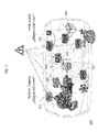
- FIG. 1 a generally designated by the reference numeral 200 vehicle having therein components that are exhaust relevant. Shown are, for example, the corresponding control units for the engine and the transmission, whose data has always been regarded as relevant for emissions and which accordingly perform measurements in accordance with legal requirements and store corresponding error information and transmitted to an external diagnostic device. With the increasing complexity of vehicles, however, more and more control devices and components of the vehicles are exhaust-relevant or are subject to the corresponding standard for on-board diagnosis. In addition to the control unit for the engine and the transmission 201 or 202, this applies in the case of hybrid vehicles, for example, the air conditioner 203, and the electric motor 204, the brake system 205, the battery 206 and the converter 207th In FIG.
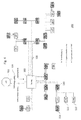
- FIG. 2 shows by way of example a corresponding vehicle architecture, wherein it can be seen that in terms of their structure according to the known from the prior art example FIG. 4 equivalent.
- the vehicle structure with respect to the corresponding components of the diagnostic system should not be changed, but the system is constructed in terms of its hierarchy in the same way as was previously known. That is, some controllers are authorized to communicate directly with the diagnostic device (GST) 50 connected to the vehicle access 2.
- the communication takes place via the gateway 3, whereby the communication takes place by means of the protocol CAN prescribed by law in the USA. That is, all in the example from FIG. 2 shown components that communicate via the so-called CAN bus, come directly into contact with the external diagnostic device 50th
- control devices downstream of this maximum of eight control devices are additional slaves or sensors or actuators which also participate in the on-board diagnosis and optionally provide error information available.
- these further units transmit error information to the control units which are connected to the CAN bus, so that they then temporarily store this information and optionally make it available to the diagnosis apparatus 50.
- the embodiment according to the invention corresponds to the procedure known from the prior art.
- the solution according to the invention is characterized by the use of a new transport protocol, which relates to the transmission of error information from downstream units to the units communicating directly with the diagnostic device 50.
- the downstream units to transmit error messages in the form of SAE-compliant error codes, at the same time containing the error code data packet containing the transmitter identifier ID.
- the error information transmitted in this way is therefore already present from the beginning in a form in which it can also be transmitted to the external diagnostic device, if necessary.
- the higher-level control unit no longer necessarily has to interpret the incoming error information and convert it into a form in which it can then be transmitted to the external diagnostic device. Accordingly, the control unit is "no matter" which subordinate unit has transmitted error information.
- This decoupling first of all has the advantage that the higher-level control unit does not have to be modified accordingly each time something changes or new units are added to the downstream units. Changes, for example, in the standard or in laws must therefore be implemented only in either the slave or the master. An adaptation of the other unit is no longer required.
- Another advantage is that the transmission of the error messages from the downstream unit to the control unit is facilitated, since previously used partly consuming procedures was ensured by the fact that only specific units were actually allowed to transmit data packets at certain times, now no longer exist , Instead, a simple error transmission in the multiplex method is possible, in addition, the possibility exists to prioritize error messages with a special diagnostic status ("fail").
- the unit also has a diagnostic status such as "pass", "fail”, "test completed”, "test not completed”. This additional information facilitates the management of the corresponding information by the master, ie the higher-level control unit.
- the so-called IUMPR status can be determined in a simple manner, since the data themselves now contain information which provides information as to whether a signal status is relevant or not.
- the information transmitted to the master additionally also contains information as to whether this is an error which should lead to activation of the engine control lamp. This, in turn, then makes it easier for the higher-level control unit to initiate the optionally required activation of the engine control light, regardless of whether the control unit knows exactly which error message is involved.
- the information additionally transmitted for this purpose can also contain information, for example, as to whether a first occurrence of the error or only a repeated occurrence of the error should lead to the activation of the indicator light. Based on this information, a corresponding reaction can then be initiated.
- FIG. 3 Another advantageous embodiment of the invention is in FIG. 3 shown.
- This training differs from the solution according to FIG. 2 primarily in the question of which device is used as the master device for the communication according to the invention. While in the embodiment according to FIG. 2 Only the control units used so far as masters took over the buffering of error information of subordinate units is now in the example according to FIG. 3 an additional master device 330 is provided whose task is to buffer error information from units of the vehicle diagnostic system and to provide the external diagnostic device. Optionally, this accessory may also initiate a corresponding activation of the engine indicator light, if required by the received error messages.
- this additional unit takes place in the manner described above, that is, SAE compliant error information is transmitted together with an ID of the sender.
- a special feature of this additional unit is that it can communicate with the external diagnostic device in a particularly fast and efficient manner. This is illustrated by the fact that in the structure of the system Unit may be arranged such that it bridges the gateway of the system and is connected directly to the diagnostic unit via the vehicle output. In this case, there is therefore a direct data connection between the external diagnostic device and the internal auxiliary device, which makes it possible for the additional device to react very quickly to a connection of the diagnostic device to the vehicle output.
- the statutory maximum response or response time of 50 ms can be easily complied with in this case, since the additional device as already mentioned can communicate directly with the external diagnostic device.
- the additional device may preferably buffer the error information of all units of the on-board diagnostic system and transmit to the external diagnostic device.
- some of the most relevant control devices such as the engine control unit, could still communicate with the diagnostic device in the past.
- a significant advantage consists in the fact that the function of the previously communicating directly with the diagnostic unit units, so the previous master control units must not be changed. Only subordinate devices must now be modified in such a way that now the auxiliary device is regarded as its associated master, to which the error information is transmitted. That is, an extension of previously existing systems by the attachment is feasible without much effort.
Abstract
Bei einem Verfahren zum Ausgeben von Fehlerinformationen eines Fahrzeugdiagnosesystems (100) an ein mit einem Fahrzeug koppelbares Diagnosegerät (50) kann das Diagnosegerät (50) mit dem Fahrzeug über einen Kommunikationsanschluss (2, 302) lösbar verbunden werden. Der Kommunikationsanschluss ist fahrzeugintem über ein Bussystem mit mindestens einem Steuergerät verbunden, welches nach Aufforderung durch das Diagnosegerät gespeicherte Fehlerinformationen an das Diagnosegerät übermittelt, wobei dem Steuergerät mindestens ein Slave (110, 111, 112, 113) nachgeordnet ist, dessen Fehlermeldungen von dem Steuergerät gespeichert und an das Diagnosegerät übermittelt werden, und wobei der Slave (110, 111, 112, 113) Fehlermeldungen an das zugeordnete Steuergerät in Form eines Fehlercodes gemeinsam mit einer den Sensor kennzeichnenden Identifikation übermittelt.

Description
Die vorliegende Erfindung betrifft ein Verfahren zum Ausgeben von Fehlerinformationen eines Fahrzeugdiagnosesystems sowie ein entsprechendes Fahrzeugdiagnosesystem mit verbesserten Möglichkeiten zur Datenausgabe an ein mit einem Fahrzeug koppelbares Diagnosegerät.The present invention relates to a method for outputting error information of a vehicle diagnostic system and to a corresponding vehicle diagnostic system with improved possibilities for data output to a diagnostic device coupleable to a vehicle.
On-Board-Diagnosesysteme dienen dazu, während des Fahrbetriebs eines Fahrzeugs alle abgasbeeinflussenden Systeme sowie weitere wichtige Steuergeräte, deren Daten zugänglich sind, zu überwachen. Auftretende Fehler sollen dabei dem Fahrer über eine Kontrollanzeige angezeigt und in dem jeweiligen Steuergerät nicht flüchtig gespeichert werden. Ferner werden entsprechende Fehlermeldungen beispielsweise während einer Wartung für genormte Schnittstellen abgefragt, was dadurch erfolgt, dass das Fahrzeug mit einem entsprechenden Diagnosegerät gekoppelt wird.On-board diagnostic systems are used to monitor all emission-control systems as well as other important ECUs whose data is accessible while a vehicle is driving. Occurring errors should be displayed to the driver via a control display and stored in the respective control unit non-volatile. Furthermore, corresponding error messages are queried, for example, during maintenance for standardized interfaces, which takes place in that the vehicle is coupled to a corresponding diagnostic device.
Derartige OBD-Systeme wurden zunächst in den USA eingeführt, sind allerdings auch in anderen Ländern gesetzlich vorgeschrieben. Grundlage für die Einführung der entsprechenden Gesetzesnormen war, dass es nicht ausreicht, sein Fahrzeug im Ausgangszustand, also bei der Zulassung die entsprechenden Abgasvorschriften einhält, sondern dass deren Einhaltung tatsächlich über die gesamte Lebensdauer des Fahrzeugs hinweg sichergestellt wird. Die Fahrzeuge müssen hierzu über eigene elektronische Systeme zur Selbstüberwachung verfügen, die bestimmte, insbesondere abgasrelevante Komponenten des Fahrzeugs überwachen. Beispiele für die von den On-Board-Diagnosesystem überwachten Funktionen sind die Lambdasondenfunktion, Verbrennungsaussetzer, der Wirkungsgrad des Katalysators sowie gegebenenfalls die Funktion der Abgasrückführung, des Sekundärluftsystems sowie das Tankentlüftungssystem. Abgasrelevante Fehler werden nicht nur über eine in den Armaturen integrierte Signal-lampe - die so genannte Motorkontrollleuchte (MIL bzw. Malfunction Indicator Light) angezeigt sondern derart gespeichert, dass sie im Rahmen einer externen Diagnose abgerufen werden können.Such OBD systems were first introduced in the US, but are also required by law in other countries. The basis for the introduction of the corresponding legal norms was that it is not enough for the vehicle to comply with the corresponding emission regulations in its initial state, ie during the approval process, but that its compliance is actually ensured throughout the lifetime of the vehicle. For this purpose, the vehicles must have their own electronic systems for self-monitoring, which monitor specific, in particular exhaust-relevant, components of the vehicle. Examples of the functions monitored by the on-board diagnostic system are the lambda sensor function, combustion misfire, the efficiency of the catalytic converter and, if appropriate, the function of the exhaust gas recirculation, the secondary air system and the tank ventilation system. Flue gas-relevant faults are not only displayed via a signal lamp integrated in the fittings - the so-called engine control lamp (MIL or Malfunction Indicator Light) but stored in such a way that they can be called up as part of an external diagnosis.
Das externe Abrufen der gespeicherten Fehlerinformationen erfolgt dadurch, dass ein externes Diagnosegerät über einen genormten Stecker mit dem Fahrzeug gekoppelt wird und die fahrzeugintern über einen Bus mit dem Stecker verbundenen Steuergeräte kontaktiert. Diese Geräte müssen dann entsprechend gesetzlich vorgeschriebenen Normen innerhalb einer bestimmten Reaktionszeit, die 50 ms bei ISOCAN beträgt, reagieren und gegebenenfalls abgespeicherte Fehlerinformationen an das Diagnosegerät übermitteln.The external retrieval of the stored error information takes place in that an external diagnostic device is coupled via a standard plug with the vehicle and the vehicle internally contacted via a bus connected to the plug control units. These devices must then comply with regulatory standards within a specific response time of 50 ms for ISOCAN, respond and possibly transmit stored error information to the diagnostic device.
Die gesetzlich vorgeschriebene Kommunikation zwischen dem Fahrzeugdiagnosesystem und dem externen Diagnosegerät schreibt allerdings nicht nur vor, dass die Steuergeräte des Diagnosesystems innerhalb einer bestimmten Zeit antworten müssen, sondern führt auch eine Beschränkung hinsichtlich der Anzahl der an der Kommunikation teilnehmenden Steuergeräte ein. So dürfen maximal acht Steuergeräte im Rahmen der entsprechenden Norm Fehlermeldungen an das Diagnosegerät übermitteln.However, the legally prescribed communication between the vehicle diagnostic system and the external diagnostic device not only dictates that the controllers of the diagnostic system must respond within a certain time, but also introduces a limitation on the number of controllers participating in the communication. For example, a maximum of eight ECUs may transmit error messages to the diagnostic device within the scope of the corresponding standard.
Es hat sich nunmehr allerdings gezeigt, dass die Begrenzung auf acht Teilnehmern an der Übermittlung von Diagnoseinformationen insofern problematisch ist, als bei neueren Fahrzeugen immer mehr Komponenten überwacht werden müssen, die im Rahmen der gesetzlichen Vorschriften Fehlerinformationen an das externe Diagnosegerät übermitteln müssen. Insbesondere durch die Einführung der Hybridtechnologie kommen nunmehr innerhalb von Fahrzeugen völlig neuartige Komponenten zum Einsatz, welche ebenfalls abgasrelevant sind und demzufolge entsprechende Informationen übermitteln sollten. Da allerdings die Anzahl der an der Kommunikation mit dem externen Diagnosegerät teilnehmenden Geräte nicht überschritten werden kann, muss nach Lösungen gesucht werden, die es trotz allem erlauben, dass sämtliche abgasrelevante Einheiten zuverlässig entsprechende Fehlerinformationen an das Diagnosegerät übermitteln können. In diesem Zusammenhang hat sich die Verwendung so genannter Master-Slave-Systeme etabliert, deren Funktion nachfolgend anhand von
Schematisch dargestellt ist in
Die verschiedenen Blöcke des Diagnosesystems 100 stellen Komponenten des Fahrzeugs dar, welche abgasrelevante Informationen erfassen und gegebenenfalls Fehlermeldungen ausgeben, die dann an das externe Diagnosegerät 150 zu übermitteln sind. Da wie bereits erwähnt maximal acht Geräte mit dem Diagnosegerät 150 kommunizieren dürfen und ferner auch entsprechend der gesetzlichen Norm nach Herstellen der Verbindung, also dem Anschließen des Diagnosegeräts 150 innerhalb von 50 ms eine Rückmeldung erfolgen muss, ist das Bussystem 105 in unterschiedliche Hierarchieebenen unterteilt. Beispielsweise stellt das mit dem Bezugszeichen 110 versehene Gerät ein abgasrelevantes Steuergerät 110 dar, welches als eines der acht Geräte mit dem Diagnosegerät kommunizieren darf. Diesem Steuergerät 110 sind allerdings weitere Einheiten 111, 112 und 113 nachgeordnet, welche beispielsweise Aktoren mit Lagerückmeldern oder anderweitige Sensoren darstellen können, deren Fehlermeldungen ebenfalls an das Diagnosegerät 150 zu übermitteln sind.The various blocks of the
Im Rahmen der Master-Slave-Lösung stellen diese weiteren Einheiten 111 bis 113 nunmehr die Slave-Einheiten dar, welche nicht unmittelbar mit dem Diagnosegerät 150 kommunizieren sondern stattdessen im Falle einer Fehlermeldung diese an das übergeordnete Master-Gerät, hier das Steuergerät 110 übermitteln. Das Steuergerät 110 speichert dann auch diese Fehlermeldungen und übermittelt diese gegebenenfalls an das Diagnosegerät 150. Letztendlich bedeutet dies, dass also von dem maximal acht zulässigen Geräten die Fehlermeldungen aller weiteren Sensoren bzw. Einheiten gesammelt und dann im Falle einer Fehlerdiagnose an das externe Diagnosegerät 150 übermittelt werden. Auf diesem Wege ist sichergestellt, dass bei einer beliebigen Anzahl von abgasrelevanten Einheiten trotz allem die zulässige Maximalzahl an kommunizierenden Geräten nicht überschritten wird.In the context of the master-slave solution, these
Die Kommunikation zwischen den maximal acht Geräten und dem externen Diagnosegerät muss über ein standardisiertes Diagnoseprotokoll (SAEJ1979) erfolgen. Die Fehlermeldungen müssen im Rahmen dieser Norm durch spezielle Fehlercodes an das externe Diagnosegerät übermittelt werden. Die oben erwähnten untergeordneten Slave-Einheiten übermitteln allerdings Fehlerinformationen im Rahmen bestimmter Datenpakete an die zugehörigen Master-Einheiten, welche Fehlerbits enthalten, die gegebenenfalls über auftretende Fehler Auskunft geben. Diese Datenpakete entsprechen allerdings nicht den in der oben erwähnten Norm vorgeschriebenen Fehlercodes, sodass durch den jeweiligen Master eine entsprechende Umsetzung erforderlich ist, bevor die Fehlermeldungen an das externe Diagnosegerät übermittelt werden können.Communication between the maximum of eight devices and the external diagnostic device must be via a standardized diagnostic protocol (SAEJ1979). Within the scope of this standard, the error messages must be transmitted to the external diagnostic device by means of special error codes. The above-mentioned subordinate slave units, however, transmit error information in the context of certain data packets to the associated master units, which contain error bits that possibly provide information about errors that occur. However, these data packets do not correspond to the error codes prescribed in the above-mentioned standard, so that the respective master requires a corresponding conversion before the error messages can be transmitted to the external diagnostic device.
Ferner muss das Master-Gerät Kenntnis darüber besitzen, wie viele Geräte als Slave-Einheiten mit ihm verbunden sind. Außerdem ist in der Regel ein spezielles Multiplex-Verfahren zur Datenübermittlung zwischen Master-Einheit und Slave-Einheiten vorgesehen, durch welche sichergestellt ist, dass die Master-Einheit tatsächlich in der Lage ist, eintreffende Informationen richtig zu interpretieren und dann normgerecht an das Diagnosegerät zu übermitteln. Dies wiederum bedeutet allerdings, dass bei einer Änderung der Slave-Einheiten auch eine entsprechende Anpassung in der Konfiguration der Master-Einheit vorgenommen werden muss, was zu verhältnismäßig hohem Aufwand führt.Furthermore, the master device must know how many devices are connected to it as slave units. In addition, a special multiplex method for data transmission between the master unit and slave units is usually provided by which it is ensured that the master unit is actually able to interpret incoming information correctly and then to the diagnostic device according to standards to transfer. However, this in turn means that when changing the slave units also a corresponding adjustment in the configuration of Master unit must be made, resulting in relatively high cost.
Der vorliegenden Erfindung liegt deshalb die Aufgabenstellung zugrunde, eine neue Möglichkeit zum Ausgeben von Fehlerinformationen bei einem Fahrzeugdiagnosesystem anzugeben, bei dem die oben beschriebenen Probleme vermieden werden.The present invention is therefore based on the object to provide a new way to output error information in a vehicle diagnostic system, in which the problems described above are avoided.
Die Aufgabe wird durch ein Verfahren zum Ausgeben von Fehlerinformationen eines Fahrzeugdiagnosesystems gemäß Anspruch 1 sowie durch ein Fahrzeugdiagnosesystem gemäß Anspruch 10 gelöst. Vorteilhafte Weiterbildungen der Erfindung sind Gegenstand der abhängigen Ansprüche.The object is achieved by a method for outputting error information of a vehicle diagnostic system according to
Die erfindungsgemäße Lösung beruht auf dem Gedanken, die Kommunikation zwischen den Slave-Einheiten und der zugehörigen Master-Einheit derart zu gestalten, dass eine Entkopplung zwischen beiden Geräten vorliegt. Hierunter ist zu verstehen, dass keine Abhängigkeiten mehr zwischen Slave-Einheit und Master-Einheit vorliegen, die dazu führen, dass bei einer Modifizierung der Slave-Einheit auch eine entsprechende Anpassung der Master-Einheit vorgenommen werden muss. Erfindungsgemäß wird dies dadurch erreicht, dass die Master-Einheit eingehende Meldungen nicht mehr in ein konformes Format konvertiert, sondern dieses voraussetzt und die Meldungen lediglich verwaltet und an das Diagnosegerät weiterleitet. Insbesondere werden anstelle von Fehlerbits oder Fehlerflags, die von der Master-Einheit entsprechend interpretiert und in normkonforme Fehlerinformationen umgesetzt werden, nunmehr die Slave-Einheit von sich aus bereits einen entsprechenden normkonformen Fehlercode übermittelt, gemeinsam mit einer die Einheit kennzeichnenden ID.The solution according to the invention is based on the idea of designing the communication between the slave units and the associated master unit such that there is a decoupling between the two units. This means that there are no more dependencies between the slave unit and the master unit, which mean that a modification of the slave unit also requires a corresponding adaptation of the master unit. According to the invention, this is achieved in that the master unit no longer converts incoming messages into a compliant format, but presupposes this and merely manages the messages and forwards them to the diagnostic device. In particular, instead of error bits or error flags which are interpreted accordingly by the master unit and converted into standard-conform error information, the slave unit now transmits on its own a corresponding standard-compliant error code, together with an ID characterizing the unit.
Erfindungsgemäß wird dementsprechend ein Verfahren zum Ausgeben von Fehlerinformationen eines Fahrzeugdiagnosesystems an ein mit einem Fahrzeug koppelbares Diagnosegerät vorgeschlagen, wobei das Diagnosegerät mit dem Fahrzeug über einen Kommunikationsanschluss lösbar verbunden werden kann und der Kommunikationsanschluss fahrzeugintern mit mindestens einem Gerät verbunden ist, welches nach Aufforderung durch das Diagnosegerät gespeicherte Fehlerinformationen an das Diagnosegerät übermittelt. Und wobei dem die Fehlerinformation übermittelten Gerät mindestens ein Slave nachgeordnet ist, dessen Fehlermeldung von dem Gerät gespeichert und an das Diagnosegerät übermittelt wird, wobei erfindungsgemäß der Slave Fehlermeldungen an das zugeordnete Steuergerät in Form eines Fehlercodes gemeinsam mit einer den Slave kennzeichnenden Identifikation übermittelt. Insbesondere werden hierbei von der Slave-Einheit bereits die SAE-konformen Fehlercodes übermittelt.According to the invention, a method is accordingly proposed for outputting error information of a vehicle diagnostic system to a diagnostic device that can be coupled to a vehicle, wherein the diagnostic device can be detachably connected to the vehicle via a communication port and the communication port is connected in-vehicle with at least one device which, upon request by the diagnostic device stored error information to the diagnostic device. And wherein the device transmitting the error information is arranged downstream of at least one slave whose error message is stored by the device and transmitted to the diagnostic device, according to the invention the slave transmits error messages to the associated control device in the form of an error code together with an identifying the slave identification. In particular, the slave unit already transmits the SAE-compliant error codes.
Die neuartige Ausgestaltung der Kommunikation zwischen Master- und Slave-Einheit führt wie bereits erwähnt zu einer Entkopplung zwischen beiden Geräten. Bei einem Wechsel bzw. einer Änderung des entsprechenden SAE-Fehlercodes ist dementsprechend allenfalls eine entsprechende Änderung der Slave-Einheit erforderlich. Auch können durch entsprechende Ausgestaltung der Slave-Einheit in einfacher Weise neuartige Diagnosen hinzugefügt werden bzw. auf Diagnosen verzichtet werden. In all diesen Fällen ist lediglich eine Anpassung des Slave erforderlich, nicht jedoch der Master-Einheit. Ferner können entsprechende Fehlermeldungen effizient in Datenpakete gebündelt werden, sodass die Buslast also die Menge der über das Bussystem zu übermittelnden Daten minimiert werden kann. Ein weiterer Vorteil ergibt sich darin, dass abhängig von der Anzahl der Diagnosen nur eine Botschaft erforderlich ist.The novel design of the communication between master and slave unit leads as already mentioned to a decoupling between the two devices. In case of a change or a change of the corresponding SAE error code, accordingly, at most a corresponding change of the slave unit is required. Also can be added by appropriate design of the slave unit in a simple way new diagnoses or dispense with diagnoses. In all these cases, only an adjustment of the slave is required, but not the master unit. Furthermore, corresponding error messages can be bundled efficiently into data packets, so that the bus load, ie the amount of data to be transmitted via the bus system, can be minimized. Another advantage is that depending on the number of diagnoses, only one message is required.
Dabei kann gemäß einer Weiterbildung des erfindungsgemäßen Systems auch vorgesehen sein, dass zusätzlich zu den SAE-konformen Fehlercodes auch mehrere Einzelfehler übermittelt werden können. Dies kann insofern von Interesse sein, als durch das gesetzlich vorgeschriebene Diagnosegerät bestimmte Fehlermeldungen abgefragt werden, im Falle einer Wartung und dem Fahrzeughersteller jedoch gegebenenfalls noch zusätzliche Informationen abgefragt werden sollen, die detaillierte Auskunft über etwaige Probleme der Fahrzeugsteuerung geben können. Eine entsprechende Erweiterung der erfindungsgemäßen Kommunikation dahingehend, dass detailliert Informationen über Einzelfehler übermittelt werden, ist jederzeit möglich.It can also be provided according to a development of the system according to the invention that in addition to the SAE-compliant error codes and multiple individual errors can be transmitted. This may be of interest insofar as certain error messages are interrogated by the legally prescribed diagnostic device, but in the case of maintenance and the vehicle manufacturer, additional information may be required, which may provide detailed information about any problems of vehicle control. A corresponding extension of the communication according to the invention in that detailed information about individual errors is transmitted is possible at any time.
Eine andere Weiterbildung des erfindungsgemäßen Konzepts kann auch darin bestehen, dass die von der Slave-Einheit an den Master übermittelte Information auch Auskunft darüber gibt, ob der Fehler zu einer entsprechenden Aktivierung der Motorkontrollleuchte (MIL) führen soll. Dies ist insofern wesentlich, als gemäß der erfindungsgemäßen Lösung nunmehr die Master-Einheit von der Aufgabe entbunden ist, die übermittelten Informationen zu interpretieren und in die normkonformen Fehlercodes umzusetzen. Das heißt, die Master-Einheit muss im Prinzip die übermittelten Fehlercodes von den Slave-Einheiten gar nicht verstehen. Für den Fall jedoch, dass es sich um Fehler handelt, die entsprechend den Vorschriften zu einem Aktivieren der Motorkontrollleuchte führen müssen, kann dies dem Master bei der Übermittlung der Fehlercodes entsprechend angezeigt werden. Wiederum muss der Master den Fehlercode zwar nicht verstehen, er weiß nun allerdings, dass die Fehlermeldung zu einer Aktivierung der Motorkontrollleuchte führen soll (ohne dass er weiß, um was für einen Fehler es sich handelt), wobei noch die Zusatzinformation enthalten sein kann, ob bereits beim ersten Auftreten des Fehlers oder - wie dies bei den meisten Fehlern der Fall ist - erst nach mehrmaligem, beispielsweise dem zweiten oder dritten wiederholten Auftreten des Fehlers die Motorkontrollleuchte aktiviert werden soll. Das heißt, alle Vorschriften bezüglich der Übermittlung von Fehlerinformationen bzw. der Aktivierung der Motorkontrollleuchte können in gewohnter Weise zuverlässig erfüllt werden, wobei jedoch der oben erwähnte Vorteil der Entkopplung zwischen Master- und Slave-Einheit erzielt wird.Another development of the inventive concept may also consist in that the information transmitted by the slave unit to the master also provides information as to whether the fault should lead to a corresponding activation of the engine control lamp (MIL). This is essential insofar as, according to the inventive solution, the master unit is now released from the task of interpreting the transmitted information and converting it into the standard-compliant error codes. That is, the master unit does not have to understand the transmitted error codes from the slave units in principle. In the event, however, that these are faults which, according to the regulations, must lead to activation of the engine control light, this can be displayed accordingly to the master when the fault codes are transmitted. Again, the master does not have to understand the error code, but now he knows that the error message should lead to an activation of the engine control lamp (without him knowing what an error it is), which may contain the additional information, whether already at the first occurrence of the error or - as is the case with most errors - only after repeated, for example, the second or third repeated occurrence of the error, the engine control lamp is to be activated. That is, all regulations with respect to the transmission of error information or the activation of the engine control lamp can be reliably fulfilled in the usual manner, however, the above-mentioned advantage of the decoupling between master and slave unit is achieved.
Bei der Master-Einheit der erfindungsgemäßen Lösung kann es sich um eine Steuereinheit des Fahrzeugs handeln, wobei in diesem Fall dann das System hinsichtlich seines Aufbaus demjenigen von
Letztendlich wird also durch die erfindungsgemäße Lösung das Ausgeben von Fehlerinformationen an ein externes Diagnosegerät deutlich optimiert.Ultimately, therefore, the output of error information to an external diagnostic device is significantly optimized by the inventive solution.
Nachfolgend soll die Erfindung anhand der beiliegenden Zeichnungen näher erläutert werden. Es zeigen:
Figur 1- schematisch ein Fahrzeug mit darin befindlichen abgasrelevanten Steuergeräten, welche im Rahmen einer On-Board-Diagnose Fehlerinformationen speichern und gegebenenfalls an ein externes Diagnosegerät übermitteln müssen;
Figur 2- beispielhaft eine entsprechende Fahrzeugarchitektur mit den zur Durchführung der Online-Diagnose verantwortlichen Komponenten;
Figur 3- eine vorteilhafte Weiterbildung des erfindungsgemäßen Diagnosesystems und
Figur 4- schematisch eine Fahrzeugarchitektur gemäß dem Stand der Technik.
- FIG. 1
- schematically a vehicle with therein located exhaust-related control devices, which must store error information as part of an on-board diagnosis and possibly transmit to an external diagnostic device;
- FIG. 2
- by way of example, a corresponding vehicle architecture with the components responsible for carrying out the online diagnosis;
- FIG. 3
- an advantageous embodiment of the diagnostic system according to the invention and
- FIG. 4
- schematically a vehicle architecture according to the prior art.
In
Diesen maximal acht Steuergeräten nachgeordnet sind allerdings weitere Slaves bzw. Sensoren oder Aktoren welche ebenfalls an der On-Board-Diagnose teilnehmen und gegebenenfalls Fehlerinformationen zur Verfügung stellen. Im Rahmen des bereits eingangs erwähnten Master-Slave-Prinzips ist nunmehr vorgesehen, dass diese weiteren Einheiten an die Steuergeräte, welche an den CAN-Bus angeschlossen sind, Fehlerinformationen übermitteln, sodass diese dann diese Informationen zwischenspeichern und gegebenenfalls dem Diagnosegerät 50 zur Verfügung stellen. Insofern entspricht die erfindungsgemäße Ausführungsform der aus dem Stand der Technik bekannten Vorgehensweise. Allerdings zeichnet sich die erfindungsgemäße Lösung durch den Einsatz eines neuen Transportprotokolls aus, welches die Übermittlung von Fehlerinformationen von nachgeordneten Einheiten an die unmittelbar mit dem Diagnosegerät 50 kommunizierenden Einheiten betrifft. Dabei ist nunmehr vorgesehen, dass die nachgeordneten Einheiten Fehlermeldungen in Form SAE-konformer Fehlercodes übermitteln, wobei gleichzeitig das den Fehlercode beinhaltende Datenpaket eine den Sender kennzeichnende ID enthält. Die auf diese Art und Weise übermittelte Fehlerinformation liegt also bereits von Anfang an in einer Form vor, in der sie auch gegebenenfalls an das externe Diagnosegerät übermittelt werden kann. Das übergeordnete Steuergerät muss in diesem Fall also nicht mehr zwingend die eintreffende Fehlerinformation interpretieren und in eine Form umsetzen, in der sie dann an das externe Diagnosegerät übermittelt werden kann. Dem Steuergerät ist es dementsprechend "egal" von welcher nachgeordneten Einheit eine Fehlerinformation übermittelt wurde. Diese Entkopplung bringt zunächst einmal den Vorteil mit sich, dass das übergeordnete Steuergerät nicht jedes Mal entsprechend modifiziert werden muss, wenn sich an den nachgeordneten Einheiten etwas ändert bzw. neue Einheiten hinzugefügt werden. Änderungen beispielsweise in der Norm oder in Gesetzen müssen dementsprechend lediglich entweder im Slave oder im Master umgesetzt werden. Eine Anpassung der jeweils anderen Einheit ist nicht mehr länger erforderlich.However, downstream of this maximum of eight control devices are additional slaves or sensors or actuators which also participate in the on-board diagnosis and optionally provide error information available. Within the scope of the already mentioned master-slave principle, it is now provided that these further units transmit error information to the control units which are connected to the CAN bus, so that they then temporarily store this information and optionally make it available to the
Ein weiterer Vorteil besteht darin, dass das Übertragen der Fehlermeldungen von der nachgeordneten Einheit zu der Steuereinheit erleichtert wird, da bislang zum Einsatz kommende teils aufwändige Verfahren durch die sichergestellt war, dass tatsächlich zu bestimmten Zeitpunkten lediglich bestimmte Einheiten Datenpakete übermitteln durften, nunmehr nicht mehr bestehen. Stattdessen ist eine einfache Fehlerübertragung im Multiplex-Verfahren möglich, wobei darüber hinaus auch die Möglichkeit besteht Fehlermeldungen mit speziellem Diagnosestatus ("fail") zu priorisieren. Generell kann es von Vorteil sein, wenn zusätzlich zu der Fehlermeldung auch durch die Einheit ein Diagnosestatus wie beispielweise "pass", "fail", "Test completed", "Test not completed", übermittelt wird. Diese zusätzliche Information erleichtert die Verwaltung der entsprechenden Informationen durch den Master, also das übergeordnete Steuergerät. Ferner kann sichergestellt werden, dass der so genannte IUMPR-Status in einfacher Weise ermittelt werden kann, da die Daten selbst nunmehr Informationen enthalten, die Auskunft darüber geben, ob ein Signalstatus relevant ist oder nicht.Another advantage is that the transmission of the error messages from the downstream unit to the control unit is facilitated, since previously used partly consuming procedures was ensured by the fact that only specific units were actually allowed to transmit data packets at certain times, now no longer exist , Instead, a simple error transmission in the multiplex method is possible, in addition, the possibility exists to prioritize error messages with a special diagnostic status ("fail"). In general, it may be advantageous if, in addition to the error message, the unit also has a diagnostic status such as "pass", "fail", "test completed", "test not completed". This additional information facilitates the management of the corresponding information by the master, ie the higher-level control unit. Furthermore, it can be ensured that the so-called IUMPR status can be determined in a simple manner, since the data themselves now contain information which provides information as to whether a signal status is relevant or not.
Wie vorher bereits erwähnt ist im Rahmen der On-Board-Diagnose darüber hinaus auch vorgesehen, dass bestimmte Fehlermeldungen zur Aktivierung der Motorkontrollleuchte in dem Fahrzeug führen. Gemäß einer weiteren vorteilhaften Weiterbildung der Erfindung kann deshalb vorgesehen sein, dass die an den Master übermittelte Information zusätzlich auch eine Information dahingehend enthält, ob es sich hierbei um einen Fehler handelt, der zum Aktivieren der Motorkontrollleuchte führen sollte. Dies erleichtert wiederum dann der übergeordneten Steuereinheit das gegebenenfalls erforderliche Aktivieren der Motorkontrollleuchte einzuleiten, und zwar unabhängig davon, dass das Steuergerät weiß, um welche Fehlermeldung genau es sich handelt. Die hierzu zusätzlich übertragene Information kann beispielsweise dann auch Informationen beinhalten, ob ein erstmaliges Auftreten des Fehlers oder erst ein mehrmaliges Auftreten des Fehlers zum Aktivieren der Kontrollleuchte führen sollte. Basierend auf diesen Informationen kann dann eine entsprechende Reaktion veranlasst werden.As previously mentioned, in the context of the on-board diagnosis, moreover, it is also provided that certain error messages lead to the activation of the engine control lamp in the vehicle. According to a further advantageous development of the invention, it can therefore be provided that the information transmitted to the master additionally also contains information as to whether this is an error which should lead to activation of the engine control lamp. This, in turn, then makes it easier for the higher-level control unit to initiate the optionally required activation of the engine control light, regardless of whether the control unit knows exactly which error message is involved. The information additionally transmitted for this purpose can also contain information, for example, as to whether a first occurrence of the error or only a repeated occurrence of the error should lead to the activation of the indicator light. Based on this information, a corresponding reaction can then be initiated.
Eine andere vorteilhafte Weiterbildung der Erfindung ist in
Die Kommunikation zwischen den nachgeordneten Einheiten und diesem zusätzlichen Gerät 330 erfolgt in der oben beschriebenen Weise, das heißt, es werden SAEkonforme Fehlerinformationen gemeinsam mit einer ID des Senders übermittelt. Eine Besonderheit dieser zusätzlichen Einheit besteht nunmehr allerdings darin, dass diese in besonders schneller und effizienter Weise mit dem externen Diagnosegerät kommunizieren kann. Dies wird dadurch dargestellt, dass in der Struktur des Systems diese Einheit derart angeordnet werden kann, dass sie das Gateway des Systems überbrückt und unmittelbar über den Fahrzeugausgang mit dem Diagnosegerät verbunden wird. In diesem Fall liegt also eine direkte Datenverbindung zwischen externem Diagnosegerät und internem Zusatzgerät vor, welche es ermöglicht, dass das Zusatzgerät sehr schnell auf eine Verbindung des Diagnosegeräts mit dem Fahrzeugausgang reagieren kann. Die gesetzlich vorgeschriebene maximale Response- bzw. Antwortzeit von 50 ms kann in diesem Fall problemlos eingehalten werden, da das Zusatzgerät wie bereits erwähnt unmittelbar mit dem externen Diagnosegerät kommunizieren kann.The communication between the downstream units and this
Das zusätzliche Gerät kann dabei vorzugsweise die Fehlerinformationen aller Einheiten des On-Board-Diagnosesystems Zwischenspeichern und an das externe Diagnosegerät übermitteln. Alternativ hierzu könnten allerdings einige der besonders relevanten Steuergeräte, beispielsweise das Motorsteuergerät, nach wie vor in bisheriger Weise mit dem Diagnosegerät kommunizieren. Ein wesentlicher Vorteil besteht dabei darin, dass die Funktion der bislang unmittelbar mit dem Diagnosegerät kommunizierenden Einheiten, also der bisherigen Master-Steuergeräte nicht verändert werden muss. Lediglich nachgeordnete Geräte müssen nunmehr derart modifiziert werden, dass nunmehr das Zusatzgerät als ihr zugehöriger Master angesehen wird, an den die Fehlerinformationen übermittelt werden. Das heißt, eine Erweiterung bislang bestehender Systeme durch das Zusatzgerät ist ohne großen Aufwand durchführbar.The additional device may preferably buffer the error information of all units of the on-board diagnostic system and transmit to the external diagnostic device. Alternatively, however, some of the most relevant control devices, such as the engine control unit, could still communicate with the diagnostic device in the past. A significant advantage consists in the fact that the function of the previously communicating directly with the diagnostic unit units, so the previous master control units must not be changed. Only subordinate devices must now be modified in such a way that now the auxiliary device is regarded as its associated master, to which the error information is transmitted. That is, an extension of previously existing systems by the attachment is feasible without much effort.
Letztendlich wird also durch die erfindungsgemäße Lösung sichergestellt, dass die Übermittlung von Fehlerinformationen im Rahmen der gesetzlich vorgeschriebenen On-Board-Diagnose in gewohnt zuverlässiger Weise realisiert werden kann. Durch den Einsatz eines neuen Kommunikationsprotokolls jedoch kann deutlich flexibler auf Änderungen in den entsprechenden Normen/Gesetzen bzw. in den die Fehlerinformation liefernden Slave-Einheiten reagiert werden.Ultimately, therefore, it is ensured by the inventive solution that the transmission of error information in the context of legally prescribed on-board diagnosis can be realized in the usual reliable manner. By using a new communication protocol, however, it is possible to react much more flexibly to changes in the corresponding standards / laws or in the slave units supplying the error information.
Claims (12)
wobei das Diagnosegerät (50) mit dem Fahrzeug über einen Kommunikationsanschluss (2, 302) lösbar verbunden werden kann und der Kommunikationsanschluss fahrzeugintern über ein Bussystem mit mindestens einem Steuergerät verbunden ist, welches nach Aufforderung durch das Diagnosegerät gespeicherte Fehlerinformationen an das Diagnosegerät übermittelt, und
wobei dem Steuergerät mindestens ein Slave (110, 111, 112, 113) nachgeordnet ist, dessen Fehlermeldungen von dem Steuergerät gespeichert und an das Diagnosegerät übermittelt werden,
dadurch gekennzeichnet,
dass der Slave (110, 111, 112, 113) Fehlermeldungen an das zugeordnete Steuergerät in Form eines Fehlercodes gemeinsam mit einer den Sensor kennzeichnenden Identifikation übermittelt.A method for outputting error information of a vehicle diagnostic system (100) to a diagnostic device (50) which can be coupled to a vehicle,
wherein the diagnostic device (50) can be detachably connected to the vehicle via a communication port (2, 302) and the communication port is connected in-vehicle via a bus system to at least one control device which transmits error information stored to the diagnostic device upon request by the diagnostic device, and
wherein the control unit is followed by at least one slave (110, 111, 112, 113) whose error messages are stored by the control unit and transmitted to the diagnostic apparatus,
characterized,
that the slave (110, 111, 112, 113) error messages to the associated control device in the form of an error code transmitted together with a sensor characterizing identification.
einen Kommunikationsanschluss (2), über welchen ein mit einem Fahrzeug kuppelbares Diagnosegerät lösbar verbunden werden kann, wobei der Kommunikationsanschluss (2) fahrzeugintern über ein BUS-System mit mindestens einem Steuergerät verbunden ist, welches nach Aufforderung des Diagnosegeräts gespeicherte Fehlinformationen an das Diagnosegerät übermittelt und
wobei dem Steuergerät mindestens ein Slave nachgeordnet ist, dessen Fehlermeldungen von dem Steuergerät gespeichert und an das Diagnosegerät übermittelt werden, dadurch gekennzeichnet,
dass der Slave Fehlermeldungen an das zugeordnete Steuergerät in Form eines Fehlercodes gemeinsam mit einer den Slave kennzeichnenden Identifikation übermittelt.Vehicle diagnostic system comprising
a communication port (2) via which a diagnostic device coupleable to a vehicle can be detachably connected, wherein the communication port (2) is connected in-vehicle via a BUS system to at least one control device which transmits misinformation stored to the diagnostic device upon request of the diagnostic device;
wherein the control unit is followed by at least one slave, whose error messages are stored by the control unit and transmitted to the diagnostic apparatus, characterized
that the slave error messages transmitted to the associated control device in the form of an error code in common with a slave characterizing identification.
dadurch gekennzeichnet, dass
das Master-Steuergerät (330) derart eingerichtet ist, dass ein bereits vorhandenes Gateway (3) des Fahrzeugdiagnosesystems überbrückt und das Master-Steuergerät (330) unmittelbar mit dem Diagnosegerät verbunden werden kann, um eine direkte Datenverbindung zwischen den beiden Geräten herzustellen.A master controller (330) for use in a vehicle diagnostic system configured to store information communicated from slave devices (4, 5, 6) of the vehicle diagnostic system and to a diagnostic device via a communications port (2) of a vehicle to communicate,
characterized in that
the master controller (330) is arranged to bypass an existing gateway (3) of the vehicle diagnostic system and to connect the master controller (330) directly to the diagnostic device to establish a direct data connection between the two devices.
Priority Applications (1)
| Application Number | Priority Date | Filing Date | Title |
|---|---|---|---|
| EP14172066.4A EP2955699A1 (en) | 2014-06-12 | 2014-06-12 | Method and system for issuing error information in the on-board diagnosis of vehicles |
Applications Claiming Priority (1)
| Application Number | Priority Date | Filing Date | Title |
|---|---|---|---|
| EP14172066.4A EP2955699A1 (en) | 2014-06-12 | 2014-06-12 | Method and system for issuing error information in the on-board diagnosis of vehicles |
Publications (1)
| Publication Number | Publication Date |
|---|---|
| EP2955699A1 true EP2955699A1 (en) | 2015-12-16 |
Family
ID=50972474
Family Applications (1)
| Application Number | Title | Priority Date | Filing Date |
|---|---|---|---|
| EP14172066.4A Withdrawn EP2955699A1 (en) | 2014-06-12 | 2014-06-12 | Method and system for issuing error information in the on-board diagnosis of vehicles |
Country Status (1)
| Country | Link |
|---|---|
| EP (1) | EP2955699A1 (en) |
Cited By (3)
| Publication number | Priority date | Publication date | Assignee | Title |
|---|---|---|---|---|
| CN108881497A (en) * | 2018-08-15 | 2018-11-23 | 长安大学 | A kind of vehicle testing line long-distance intelligent diagnostic system |
| CN109213113A (en) * | 2017-07-04 | 2019-01-15 | 百度在线网络技术(北京)有限公司 | Vehicular diagnostic method and system |
| CN111352409A (en) * | 2020-04-22 | 2020-06-30 | 东风汽车集团有限公司 | Serial data bus communication control system and control method for hybrid electric vehicle |
Citations (3)
| Publication number | Priority date | Publication date | Assignee | Title |
|---|---|---|---|---|
| US6012004A (en) * | 1995-05-25 | 2000-01-04 | Komatsu Ltd. | System and method for managing time for vehicle fault diagnostic apparatus |
| WO2006077900A2 (en) * | 2005-01-19 | 2006-07-27 | Toyota Jidosha Kabushiki Kaisha | Fault diagnosis data recording system and method |
| EP2133243A1 (en) * | 2007-04-02 | 2009-12-16 | Toyota Jidosha Kabushiki Kaisha | Information recording system for vehicle |
-
2014
- 2014-06-12 EP EP14172066.4A patent/EP2955699A1/en not_active Withdrawn
Patent Citations (3)
| Publication number | Priority date | Publication date | Assignee | Title |
|---|---|---|---|---|
| US6012004A (en) * | 1995-05-25 | 2000-01-04 | Komatsu Ltd. | System and method for managing time for vehicle fault diagnostic apparatus |
| WO2006077900A2 (en) * | 2005-01-19 | 2006-07-27 | Toyota Jidosha Kabushiki Kaisha | Fault diagnosis data recording system and method |
| EP2133243A1 (en) * | 2007-04-02 | 2009-12-16 | Toyota Jidosha Kabushiki Kaisha | Information recording system for vehicle |
Cited By (4)
| Publication number | Priority date | Publication date | Assignee | Title |
|---|---|---|---|---|
| CN109213113A (en) * | 2017-07-04 | 2019-01-15 | 百度在线网络技术(北京)有限公司 | Vehicular diagnostic method and system |
| CN108881497A (en) * | 2018-08-15 | 2018-11-23 | 长安大学 | A kind of vehicle testing line long-distance intelligent diagnostic system |
| CN108881497B (en) * | 2018-08-15 | 2021-06-22 | 长安大学 | Remote intelligent diagnosis system for automobile detection line |
| CN111352409A (en) * | 2020-04-22 | 2020-06-30 | 东风汽车集团有限公司 | Serial data bus communication control system and control method for hybrid electric vehicle |
Similar Documents
| Publication | Publication Date | Title |
|---|---|---|
| DE102005044236B4 (en) | diagnostic device | |
| EP1796051B1 (en) | Diagnostics devices in a vehicle with diagnostics framework for diagnostics module | |
| EP1782034A1 (en) | Improved repair verification for electronic vehicle systems | |
| DE102004042002A1 (en) | Improved repair verification for electronic vehicle systems | |
| DE102008015352A1 (en) | Method for recording data and data recording system | |
| DE102011084254A1 (en) | Communication system for a motor vehicle | |
| WO2008006737A1 (en) | Method for operating a lin bus | |
| EP2770434B1 (en) | Method for creating an inventory of the hardware components connected to a test system of a control device | |
| EP1315332A2 (en) | Programmable data logger for CAN - systems | |
| WO2018219887A1 (en) | Maintenance of a utility vehicle | |
| EP2955699A1 (en) | Method and system for issuing error information in the on-board diagnosis of vehicles | |
| EP2307933A1 (en) | Method for programming data in at least two control devices of a motor vehicle | |
| EP2957075B1 (en) | Master bus device for a vehicle communication bus of a motor vehicle | |
| DE102012003000A1 (en) | System for diagnosing fault of vehicle, comprises central processing resource, which is configured such that it communicates wirelessly with vehicle, and communication unit, which is fixed in vehicle | |
| DE102018220605A1 (en) | Motor vehicle network and method for operating a motor vehicle network | |
| DE102009044936B4 (en) | Procedure for exchanging data | |
| DE102007045345A1 (en) | motor vehicle | |
| EP3647794B1 (en) | Method for controlling communication between a recording unit and a speed sensor of a tachograph system of a motor vehicle and corresponding tachograph system and recording unit for said tachograph system | |
| DE102011005239B4 (en) | Safety system and method for exchanging safety-related data in a safety system | |
| DE10243319B4 (en) | Secure data transmission | |
| DE102012015783A1 (en) | Method for diagnosing several vehicle components of motor car, involves actuating determined diagnostic unit by control device so that supplementary diagnosis data is provided to assigned vehicle component from diagnostic unit | |
| EP2653350A1 (en) | Vehicle network | |
| DE102005031724B4 (en) | Method and device for diagnosing electronic systems of a motor vehicle | |
| DE102016003013A1 (en) | Monitoring device and method for monitoring an operation of a control device of a motor vehicle | |
| DE102010005938A1 (en) | Safety-related functions e.g. brake functions, controlling device for rail vehicle, has direct current/direct current transducer arranged between control device and power supply to convert voltage of supply to voltage level of device |
Legal Events
| Date | Code | Title | Description |
|---|---|---|---|
| PUAI | Public reference made under article 153(3) epc to a published international application that has entered the european phase |
Free format text: ORIGINAL CODE: 0009012 |
|
| AK | Designated contracting states |
Kind code of ref document: A1 Designated state(s): AL AT BE BG CH CY CZ DE DK EE ES FI FR GB GR HR HU IE IS IT LI LT LU LV MC MK MT NL NO PL PT RO RS SE SI SK SM TR |
|
| AX | Request for extension of the european patent |
Extension state: BA ME |
|
| STAA | Information on the status of an ep patent application or granted ep patent |
Free format text: STATUS: THE APPLICATION IS DEEMED TO BE WITHDRAWN |
|
| 18D | Application deemed to be withdrawn |
Effective date: 20160617 |