EP2957246A1 - Extension device for a bone anchor, in particular for minimally invasive surgery - Google Patents
Extension device for a bone anchor, in particular for minimally invasive surgery Download PDFInfo
- Publication number
- EP2957246A1 EP2957246A1 EP14172835.2A EP14172835A EP2957246A1 EP 2957246 A1 EP2957246 A1 EP 2957246A1 EP 14172835 A EP14172835 A EP 14172835A EP 2957246 A1 EP2957246 A1 EP 2957246A1
- Authority
- EP
- European Patent Office
- Prior art keywords
- sleeve
- receiving part
- extension device
- coupled
- central axis
- Prior art date
- Legal status (The legal status is an assumption and is not a legal conclusion. Google has not performed a legal analysis and makes no representation as to the accuracy of the status listed.)
- Granted
Links
Images


Classifications
-
- A—HUMAN NECESSITIES
- A61—MEDICAL OR VETERINARY SCIENCE; HYGIENE
- A61B—DIAGNOSIS; SURGERY; IDENTIFICATION
- A61B17/00—Surgical instruments, devices or methods, e.g. tourniquets
- A61B17/16—Bone cutting, breaking or removal means other than saws, e.g. Osteoclasts; Drills or chisels for bones; Trepans
- A61B17/1604—Chisels; Rongeurs; Punches; Stamps
-
- A—HUMAN NECESSITIES
- A61—MEDICAL OR VETERINARY SCIENCE; HYGIENE
- A61B—DIAGNOSIS; SURGERY; IDENTIFICATION
- A61B17/00—Surgical instruments, devices or methods, e.g. tourniquets
- A61B17/56—Surgical instruments or methods for treatment of bones or joints; Devices specially adapted therefor
- A61B17/58—Surgical instruments or methods for treatment of bones or joints; Devices specially adapted therefor for osteosynthesis, e.g. bone plates, screws, setting implements or the like
- A61B17/68—Internal fixation devices, including fasteners and spinal fixators, even if a part thereof projects from the skin
- A61B17/70—Spinal positioners or stabilisers ; Bone stabilisers comprising fluid filler in an implant
- A61B17/7074—Tools specially adapted for spinal fixation operations other than for bone removal or filler handling
- A61B17/7076—Tools specially adapted for spinal fixation operations other than for bone removal or filler handling for driving, positioning or assembling spinal clamps or bone anchors specially adapted for spinal fixation
- A61B17/7077—Tools specially adapted for spinal fixation operations other than for bone removal or filler handling for driving, positioning or assembling spinal clamps or bone anchors specially adapted for spinal fixation for moving bone anchors attached to vertebrae, thereby displacing the vertebrae
- A61B17/708—Tools specially adapted for spinal fixation operations other than for bone removal or filler handling for driving, positioning or assembling spinal clamps or bone anchors specially adapted for spinal fixation for moving bone anchors attached to vertebrae, thereby displacing the vertebrae with tubular extensions coaxially mounted on the bone anchors
-
- A—HUMAN NECESSITIES
- A61—MEDICAL OR VETERINARY SCIENCE; HYGIENE
- A61B—DIAGNOSIS; SURGERY; IDENTIFICATION
- A61B17/00—Surgical instruments, devices or methods, e.g. tourniquets
- A61B17/16—Bone cutting, breaking or removal means other than saws, e.g. Osteoclasts; Drills or chisels for bones; Trepans
- A61B17/1662—Bone cutting, breaking or removal means other than saws, e.g. Osteoclasts; Drills or chisels for bones; Trepans for particular parts of the body
- A61B17/1671—Bone cutting, breaking or removal means other than saws, e.g. Osteoclasts; Drills or chisels for bones; Trepans for particular parts of the body for the spine
-
- A—HUMAN NECESSITIES
- A61—MEDICAL OR VETERINARY SCIENCE; HYGIENE
- A61B—DIAGNOSIS; SURGERY; IDENTIFICATION
- A61B17/00—Surgical instruments, devices or methods, e.g. tourniquets
- A61B17/16—Bone cutting, breaking or removal means other than saws, e.g. Osteoclasts; Drills or chisels for bones; Trepans
- A61B17/17—Guides or aligning means for drills, mills, pins or wires
- A61B17/1739—Guides or aligning means for drills, mills, pins or wires specially adapted for particular parts of the body
- A61B17/1757—Guides or aligning means for drills, mills, pins or wires specially adapted for particular parts of the body for the spine
-
- A—HUMAN NECESSITIES
- A61—MEDICAL OR VETERINARY SCIENCE; HYGIENE
- A61B—DIAGNOSIS; SURGERY; IDENTIFICATION
- A61B17/00—Surgical instruments, devices or methods, e.g. tourniquets
- A61B17/56—Surgical instruments or methods for treatment of bones or joints; Devices specially adapted therefor
- A61B17/58—Surgical instruments or methods for treatment of bones or joints; Devices specially adapted therefor for osteosynthesis, e.g. bone plates, screws, setting implements or the like
- A61B17/68—Internal fixation devices, including fasteners and spinal fixators, even if a part thereof projects from the skin
- A61B17/70—Spinal positioners or stabilisers ; Bone stabilisers comprising fluid filler in an implant
- A61B17/7001—Screws or hooks combined with longitudinal elements which do not contact vertebrae
- A61B17/7002—Longitudinal elements, e.g. rods
- A61B17/7011—Longitudinal element being non-straight, e.g. curved, angled or branched
-
- A—HUMAN NECESSITIES
- A61—MEDICAL OR VETERINARY SCIENCE; HYGIENE
- A61B—DIAGNOSIS; SURGERY; IDENTIFICATION
- A61B17/00—Surgical instruments, devices or methods, e.g. tourniquets
- A61B17/56—Surgical instruments or methods for treatment of bones or joints; Devices specially adapted therefor
- A61B17/58—Surgical instruments or methods for treatment of bones or joints; Devices specially adapted therefor for osteosynthesis, e.g. bone plates, screws, setting implements or the like
- A61B17/68—Internal fixation devices, including fasteners and spinal fixators, even if a part thereof projects from the skin
- A61B17/70—Spinal positioners or stabilisers ; Bone stabilisers comprising fluid filler in an implant
- A61B17/7001—Screws or hooks combined with longitudinal elements which do not contact vertebrae
- A61B17/7032—Screws or hooks with U-shaped head or back through which longitudinal rods pass
-
- A—HUMAN NECESSITIES
- A61—MEDICAL OR VETERINARY SCIENCE; HYGIENE
- A61B—DIAGNOSIS; SURGERY; IDENTIFICATION
- A61B17/00—Surgical instruments, devices or methods, e.g. tourniquets
- A61B17/56—Surgical instruments or methods for treatment of bones or joints; Devices specially adapted therefor
- A61B17/58—Surgical instruments or methods for treatment of bones or joints; Devices specially adapted therefor for osteosynthesis, e.g. bone plates, screws, setting implements or the like
- A61B17/68—Internal fixation devices, including fasteners and spinal fixators, even if a part thereof projects from the skin
- A61B17/70—Spinal positioners or stabilisers ; Bone stabilisers comprising fluid filler in an implant
- A61B17/7001—Screws or hooks combined with longitudinal elements which do not contact vertebrae
- A61B17/7035—Screws or hooks, wherein a rod-clamping part and a bone-anchoring part can pivot relative to each other
- A61B17/7037—Screws or hooks, wherein a rod-clamping part and a bone-anchoring part can pivot relative to each other wherein pivoting is blocked when the rod is clamped
-
- A—HUMAN NECESSITIES
- A61—MEDICAL OR VETERINARY SCIENCE; HYGIENE
- A61B—DIAGNOSIS; SURGERY; IDENTIFICATION
- A61B17/00—Surgical instruments, devices or methods, e.g. tourniquets
- A61B17/56—Surgical instruments or methods for treatment of bones or joints; Devices specially adapted therefor
- A61B17/58—Surgical instruments or methods for treatment of bones or joints; Devices specially adapted therefor for osteosynthesis, e.g. bone plates, screws, setting implements or the like
- A61B17/68—Internal fixation devices, including fasteners and spinal fixators, even if a part thereof projects from the skin
- A61B17/70—Spinal positioners or stabilisers ; Bone stabilisers comprising fluid filler in an implant
- A61B17/7074—Tools specially adapted for spinal fixation operations other than for bone removal or filler handling
- A61B17/7076—Tools specially adapted for spinal fixation operations other than for bone removal or filler handling for driving, positioning or assembling spinal clamps or bone anchors specially adapted for spinal fixation
- A61B17/7082—Tools specially adapted for spinal fixation operations other than for bone removal or filler handling for driving, positioning or assembling spinal clamps or bone anchors specially adapted for spinal fixation for driving, i.e. rotating, screws or screw parts specially adapted for spinal fixation, e.g. for driving polyaxial or tulip-headed screws
-
- A—HUMAN NECESSITIES
- A61—MEDICAL OR VETERINARY SCIENCE; HYGIENE
- A61B—DIAGNOSIS; SURGERY; IDENTIFICATION
- A61B17/00—Surgical instruments, devices or methods, e.g. tourniquets
- A61B17/56—Surgical instruments or methods for treatment of bones or joints; Devices specially adapted therefor
- A61B17/58—Surgical instruments or methods for treatment of bones or joints; Devices specially adapted therefor for osteosynthesis, e.g. bone plates, screws, setting implements or the like
- A61B17/68—Internal fixation devices, including fasteners and spinal fixators, even if a part thereof projects from the skin
- A61B17/70—Spinal positioners or stabilisers ; Bone stabilisers comprising fluid filler in an implant
- A61B17/7074—Tools specially adapted for spinal fixation operations other than for bone removal or filler handling
- A61B17/7083—Tools for guidance or insertion of tethers, rod-to-anchor connectors, rod-to-rod connectors, or longitudinal elements
- A61B17/7085—Tools for guidance or insertion of tethers, rod-to-anchor connectors, rod-to-rod connectors, or longitudinal elements for insertion of a longitudinal element down one or more hollow screw or hook extensions, i.e. at least a part of the element within an extension has a component of movement parallel to the extension's axis
-
- A—HUMAN NECESSITIES
- A61—MEDICAL OR VETERINARY SCIENCE; HYGIENE
- A61B—DIAGNOSIS; SURGERY; IDENTIFICATION
- A61B17/00—Surgical instruments, devices or methods, e.g. tourniquets
- A61B17/56—Surgical instruments or methods for treatment of bones or joints; Devices specially adapted therefor
- A61B17/58—Surgical instruments or methods for treatment of bones or joints; Devices specially adapted therefor for osteosynthesis, e.g. bone plates, screws, setting implements or the like
- A61B17/68—Internal fixation devices, including fasteners and spinal fixators, even if a part thereof projects from the skin
- A61B17/70—Spinal positioners or stabilisers ; Bone stabilisers comprising fluid filler in an implant
- A61B17/7074—Tools specially adapted for spinal fixation operations other than for bone removal or filler handling
- A61B17/7091—Tools specially adapted for spinal fixation operations other than for bone removal or filler handling for applying, tightening or removing longitudinal element-to-bone anchor locking elements, e.g. caps, set screws, nuts or wedges
-
- A—HUMAN NECESSITIES
- A61—MEDICAL OR VETERINARY SCIENCE; HYGIENE
- A61B—DIAGNOSIS; SURGERY; IDENTIFICATION
- A61B17/00—Surgical instruments, devices or methods, e.g. tourniquets
- A61B17/56—Surgical instruments or methods for treatment of bones or joints; Devices specially adapted therefor
- A61B17/58—Surgical instruments or methods for treatment of bones or joints; Devices specially adapted therefor for osteosynthesis, e.g. bone plates, screws, setting implements or the like
- A61B17/68—Internal fixation devices, including fasteners and spinal fixators, even if a part thereof projects from the skin
- A61B17/84—Fasteners therefor or fasteners being internal fixation devices
- A61B17/86—Pins or screws or threaded wires; nuts therefor
- A61B17/8605—Heads, i.e. proximal ends projecting from bone
-
- A—HUMAN NECESSITIES
- A61—MEDICAL OR VETERINARY SCIENCE; HYGIENE
- A61B—DIAGNOSIS; SURGERY; IDENTIFICATION
- A61B17/00—Surgical instruments, devices or methods, e.g. tourniquets
- A61B17/56—Surgical instruments or methods for treatment of bones or joints; Devices specially adapted therefor
- A61B17/58—Surgical instruments or methods for treatment of bones or joints; Devices specially adapted therefor for osteosynthesis, e.g. bone plates, screws, setting implements or the like
- A61B17/88—Osteosynthesis instruments; Methods or means for implanting or extracting internal or external fixation devices
- A61B17/8863—Apparatus for shaping or cutting osteosynthesis equipment by medical personnel
-
- A—HUMAN NECESSITIES
- A61—MEDICAL OR VETERINARY SCIENCE; HYGIENE
- A61B—DIAGNOSIS; SURGERY; IDENTIFICATION
- A61B17/00—Surgical instruments, devices or methods, e.g. tourniquets
- A61B17/56—Surgical instruments or methods for treatment of bones or joints; Devices specially adapted therefor
- A61B17/58—Surgical instruments or methods for treatment of bones or joints; Devices specially adapted therefor for osteosynthesis, e.g. bone plates, screws, setting implements or the like
- A61B17/88—Osteosynthesis instruments; Methods or means for implanting or extracting internal or external fixation devices
- A61B17/8897—Guide wires or guide pins
-
- A—HUMAN NECESSITIES
- A61—MEDICAL OR VETERINARY SCIENCE; HYGIENE
- A61B—DIAGNOSIS; SURGERY; IDENTIFICATION
- A61B17/00—Surgical instruments, devices or methods, e.g. tourniquets
- A61B17/16—Bone cutting, breaking or removal means other than saws, e.g. Osteoclasts; Drills or chisels for bones; Trepans
- A61B17/1655—Bone cutting, breaking or removal means other than saws, e.g. Osteoclasts; Drills or chisels for bones; Trepans for tapping
-
- A—HUMAN NECESSITIES
- A61—MEDICAL OR VETERINARY SCIENCE; HYGIENE
- A61B—DIAGNOSIS; SURGERY; IDENTIFICATION
- A61B17/00—Surgical instruments, devices or methods, e.g. tourniquets
- A61B17/56—Surgical instruments or methods for treatment of bones or joints; Devices specially adapted therefor
- A61B17/58—Surgical instruments or methods for treatment of bones or joints; Devices specially adapted therefor for osteosynthesis, e.g. bone plates, screws, setting implements or the like
- A61B17/68—Internal fixation devices, including fasteners and spinal fixators, even if a part thereof projects from the skin
- A61B17/70—Spinal positioners or stabilisers ; Bone stabilisers comprising fluid filler in an implant
- A61B17/7001—Screws or hooks combined with longitudinal elements which do not contact vertebrae
- A61B17/7002—Longitudinal elements, e.g. rods
- A61B17/701—Longitudinal elements with a non-circular, e.g. rectangular, cross-section
-
- A—HUMAN NECESSITIES
- A61—MEDICAL OR VETERINARY SCIENCE; HYGIENE
- A61B—DIAGNOSIS; SURGERY; IDENTIFICATION
- A61B17/00—Surgical instruments, devices or methods, e.g. tourniquets
- A61B17/56—Surgical instruments or methods for treatment of bones or joints; Devices specially adapted therefor
- A61B17/58—Surgical instruments or methods for treatment of bones or joints; Devices specially adapted therefor for osteosynthesis, e.g. bone plates, screws, setting implements or the like
- A61B17/68—Internal fixation devices, including fasteners and spinal fixators, even if a part thereof projects from the skin
- A61B17/84—Fasteners therefor or fasteners being internal fixation devices
- A61B17/86—Pins or screws or threaded wires; nuts therefor
- A61B17/8605—Heads, i.e. proximal ends projecting from bone
- A61B17/861—Heads, i.e. proximal ends projecting from bone specially shaped for gripping driver
-
- A—HUMAN NECESSITIES
- A61—MEDICAL OR VETERINARY SCIENCE; HYGIENE
- A61B—DIAGNOSIS; SURGERY; IDENTIFICATION
- A61B17/00—Surgical instruments, devices or methods, e.g. tourniquets
- A61B17/56—Surgical instruments or methods for treatment of bones or joints; Devices specially adapted therefor
- A61B17/58—Surgical instruments or methods for treatment of bones or joints; Devices specially adapted therefor for osteosynthesis, e.g. bone plates, screws, setting implements or the like
- A61B17/88—Osteosynthesis instruments; Methods or means for implanting or extracting internal or external fixation devices
- A61B17/8866—Osteosynthesis instruments; Methods or means for implanting or extracting internal or external fixation devices for gripping or pushing bones, e.g. approximators
-
- A—HUMAN NECESSITIES
- A61—MEDICAL OR VETERINARY SCIENCE; HYGIENE
- A61B—DIAGNOSIS; SURGERY; IDENTIFICATION
- A61B17/00—Surgical instruments, devices or methods, e.g. tourniquets
- A61B17/56—Surgical instruments or methods for treatment of bones or joints; Devices specially adapted therefor
- A61B17/58—Surgical instruments or methods for treatment of bones or joints; Devices specially adapted therefor for osteosynthesis, e.g. bone plates, screws, setting implements or the like
- A61B17/88—Osteosynthesis instruments; Methods or means for implanting or extracting internal or external fixation devices
- A61B17/8875—Screwdrivers, spanners or wrenches
-
- A—HUMAN NECESSITIES
- A61—MEDICAL OR VETERINARY SCIENCE; HYGIENE
- A61B—DIAGNOSIS; SURGERY; IDENTIFICATION
- A61B17/00—Surgical instruments, devices or methods, e.g. tourniquets
- A61B17/02—Surgical instruments, devices or methods, e.g. tourniquets for holding wounds open; Tractors
- A61B17/025—Joint distractors
- A61B2017/0256—Joint distractors for the spine
Definitions
- the invention relates to an extension device for a bone anchor, in particular for use in minimally invasive surgery (MIS).
- the invention also relates to a system including such an extension device and a bone anchor, wherein the bone anchor comprises an anchoring section and a receiving part for receiving a rod to couple the rod to the anchoring section.
- the extension device includes a first sleeve and a second sleeve that are each configured to be coupled to the receiving part in such a manner that a translational and a rotational movement of the extension device relative to the receiving part is inhibited.
- a locking member is provided that guarantees correct decoupling of the sleeves from the receiving part.
- Extension devices also called head extenders, for pedicle screws for use in minimally invasive surgery are known in the art.
- US 7,563,264 B2 describes a spinal stabilization system for a minimally invasive procedure wherein detachable sleeves may be coupled to a collar of a bone anchor to allow for formation of the spinal stabilization system through a small skin incision.
- the detachable sleeve members may allow for alignment of the collars to facilitate insertion of an elongated member in the collars.
- a coupling system is provided between the sleeve and the collar that inhibits translational movement of the sleeve relative to the collar.
- the sleeve may be coupled to a collar of a bone fastener assembly with movable members that may be threaded into threaded openings in the collar.
- WO 2013/112689 A2 describes a minimally invasive tower access device comprising an elongated outer sleeve that slidably receives an elongated inner sleeve.
- a lock nut is used to secure the inner sleeve and outer sleeve in a locked mode.
- an extension device for a bone anchor that is not only safe during use in the surgical steps, such as compression and distraction, but that is also safe during the step of decoupling from the receiving part.
- the extension device is configured to be coupled to the receiving part such that it is locked against translational and rotational movement of the extension device relative to the receiving part. Because translational and rotational movements of the extension device and the receiving part are inhibited, the connection between the extension device and the receiving part is robust. This permits a safe placement of the rod and a set screw for fixing the rod. Surgical steps of adjustment of the spinal stabilization system, such as compression or distraction can be performed using the extension device attached to the receiving part, once the bone anchor has been inserted into the bone.
- the coupling between the extension device and the receiving part is effected by a formfit engagement of a portion of the extension device with a portion of the receiving part.
- the coupling is effected by a frictional engagement of a portion of the extension device with a portion of the receiving part.
- the coupling can also be partially a form-fit coupling and partially a friction-fit coupling.
- the extension device comprises a first sleeve and a second sleeve positioned within the first sleeve and an interlocking bushing that connects the second sleeve to the first sleeve and allows a controlled axial movement of the second sleeve relative to the first sleeve.
- a translational movement between the extension device and the receiving part can be inhibited by a form-fit engagement of a circumferential rib that extends at least partially around the longitudinal axis of the device and engages a corresponding circumferential groove.
- the rib may be provided at the first sleeve and the groove at the receiving part or vice versa.
- first sleeve may be coupled to the receiving part by means of a form-fit connection and the second sleeve may be coupled to the receiving part by a friction-fit conection only or vice versa
- Decoupling of the extension device from the receiving part can be carried out only in a prescribed sequence of steps which in one embodiment consists in a first step of decoupling the second sleeve and a second step of decoupling the first sleeve.
- the correct sequence of steps is guaranteed by the presence of a locking member that, in a first configuration, inhibits the decoupling of the first sleeve when the second sleeve is still coupled to the receiving part.
- the locking member is in a second configuration after decoupling the second sleeve, the decoupling of the first sleeve is allowed.
- a damage of the extension device based on erroneous operation is prevented.
- the surgeon can perform a next step in the surgical procedure only after correct decoupling of the extension device. This enhances the safety of the procedure.
- the extension device may comprise a third sleeve that can be removably connected to the first sleeve in order to provide an extension device having an increased length.
- a surgical procedure may be started with the longer extension device that comprises the third sleeve attached to the first sleeve for placement of the rod and the set screw. Thereafter, the third sleeve may be removed in order to improve the placement of the receiving part relative to the rod during compression and distraction steps. With the shorter extension device a greater variety of angles of the receiving parts relative to each other may be obtained.
- the extension device comprises only few parts which facilitate the assembly and operation of the device.
- the extension device may be used together with a release or decoupling instrument that is adapted to engage the extension device.
- the locking member of the extension device is configured to be engaged by the decoupling instrument in its second configuration only. It cannot be engaged in the first configuration in which both, the first and the second sleeve are coupled to the receiving part.
- the system of the extension device and the decoupling instrument guarantees the safety of handling and prevents damage of parts of the extension device or the receiving part.
- the spinal stabilization system includes at least two bone anchors with receiving parts that are adapted to be used with the extension device.
- an extension device includes a first sleeve 1 that forms an outer sleeve, a second sleeve 2 that forms an inner sleeve and that is positionable within the first sleeve 1 and an interlocking bushing 3.
- the interlocking bushing 3 is configured to be connected to the second sleeve 2 and is configured to couple the second sleeve 2 to the first sleeve 1 such as to permit a controlled motion of the second sleeve 2 relative to the first sleeve 1.
- a third sleeve 4 may be included in the extension device.
- the third sleeve 4 can be removably attached to the first sleeve 1 to extend the length of the first sleeve 1.
- the extension device can be used to place the parts of a spinal stabilization system in a patient's body using a minimally invasive procedure. For some particular steps in the surgical procedure, the third sleeve 4 may be removed.
- the extension device shown in Figs. 1 to 3 is configured to be used with a bone anchor for example with a pedicle screw.
- a bone anchor for example with a pedicle screw.
- an example of such a bone anchor may comprise an anchoring element with a threaded shank 100 and a spherical segment-shaped head 101, wherein the anchoring element is pivotably coupled to a receiving part 200.
- the receiving part is shown in more detail in Figs. 5 to 7b .
- the receiving part may be formed as a substantially cylindrical part with a first end or top end 200a and a second end or bottom end 200b, a central axis C, a coaxial bore 201 extending from the top end 200a to a distance from the bottom end 200b, and a seat 202 for the head 101 of the anchoring element as well as a lower opening 203 at the bottom end 200b where the shank of the bone anchoring element can pass through.
- a substantially U-shaped recess 204 may extend from the top end 200a in the direction of the bottom end 200b.
- the recess 204 serves for receiving a rod (not shown) therein. By means of the recess 204 two free legs 205a, 205b are formed.
- circumferentially extending grooves 206a, 206b are formed that extend from one end of the channel formed by the U-shaped recess 204 to the other end and that are open towards the U-shaped recess 204.
- An upper sidewall 206a', 206b' and a lower sidewall 206a", 206b" of the groove 206a, 206b may be inclined towards the bottom end 200b.
- the receiving part 200 may further include at the top end 200a in a free end surface of each of the legs 205a, 205b a recess 207a, 207b that extends into the legs in a direction parallel to the central axis C.
- the recess 207a, 207b is in a top view elongate and closed in a circumferential direction at both ends. Both recesses 207a; 207b serve for engagement with a portion of the extension device as described below.
- the receiving part 200 may comprise a pair of longitudinal grooves 212a at one side of the U-shaped recess 204 and a pair of longitudinal grooves 212b at the opposite side.
- the grooves of each pair of grooves 212a, 212b are spaced apart from each other in the circumferential direction.
- the grooves extend from the top end 200a in the outer wall of the receiving part on either side of the recesses 207a, 207b and are open towards the top end 200a.
- the grooves may have a decreasing depth towards their closed end that is located at a distance from the top end 200a.
- the cross-section of the longitudinal grooves 212a, 212b is substantially rectangular. As illustrated in particular in Fig.
- the longitudinal grooves 212a, 212b intersect the circumferentially extending grooves 206a, 206b.
- the grooves 212a, 212b may interact with corresponding longitudinally extending pairs of ribs of the first sleeve in order to provide a form-fit connection.
- an internal thread 209 may be provided for cooperating with a locking screw (not shown) for fixing the rod.
- the first sleeve 1 of the extension device is elongate and comprises a longitudinal axis c that is coaxial with the central axis C of the receiving part 200 when the extension device is coupled to the receiving part.
- the first sleeve 1 further has a front end 1a and a rear end 1b.
- a first section 11 Adjacent to the rear end 1b, a first section 11 is provided with an inner diameter that is greater than an inner diameter of a following second section 12. Two small projections 11 a, 11b protrude from the rear end 1b. They may interact with recesses in the third sleeve 4 for correct positioning of the third sleeve 4 onto the first sleeve 1.
- the second section 12 that follows the first section 11 serves the function of providing a clamping portion for the interlocking bushing 3 as described below.
- a third section 13 Adjacent to the second section 12, a third section 13 follows that may have a slightly smaller inner diameter compared to the second section 12. In the third section 13, an internal thread 15 is provided that is configured to interact with the interlocking bushing 3.
- the internally threaded section 15 is preferably adjacent to the second section 12.
- the first sleeve 1 may be in a portion thereof at 90° offset from the projections 11a, 11b double-walled by means of arc-shaped or cylinder segment-shaped longitudinal recesses 19c, 19d.
- the first sleeve 1 may further comprise in its outer wall at a first distance from the rear end 1b two opposite first transverse recesses 15a, 15b that serve for attaching an instrument to the first sleeve 1.
- the recesses 15a, 15b may be at circumferential positions corresponding to the small projections 11a, 11b.
- two second recesses 16a, 16b may be provided, that extend in a circumferential direction and that are substantially 90° offset from the recesses 15a, 15b.
- the second transverse recesses 16a, 16b extend fully through an outermost wall of the first sleeve 1 and may serve for cleaning purposes to provide access to the recesses 19c, 19d.
- Two elongate substantially U-shaped slits 17a, 17b that have a reverse U-shape compared to the slit 204 in the receiving part and that are offset from each other by 180° extend from the front end 1a towards the rear end 1b up to a distance from the second section 12 of the first sleeve 1.
- the longitudinal slits 17a, 17b have a width in a circumferential direction that is greater than a diameter of a spinal stabilization rod such that they permit to insert the rod through the slits.
- the width of the slits 17a, 17b is substantially the same as the width of the U-shaped recess of the receiving part 200.
- the length of the slits 17a, 17b is typically more than 1/3 of the length of the first sleeve, preferably more than 1/2 of the length of the first sleeve. They can even be longer than 3/4 of the length of the first sleeve.
- the slits are located at a position that is offset by approximately 90° from the position of the first recesses 15a, 15b.
- two free legs 18a, 18b are formed that serve the purpose of interacting with the free legs 205a, 205b of the receiving part 200.
- the first sleeve 1 is slightly flexible in a direction perpendicular to the sleeve axis, so that the first sleeve 1 can be snapped onto the legs 205a, 205b of the receiving part 200.
- the inner surface of the third section 13 of the first sleeve 1 comprises at each of the legs 18a, 18b a longitudinally extending substantially arc-shaped or cylinder segment-shaped guiding recess 19a, 19b into which a portion of the second sleeve 2 can extend to be guided therein.
- the guiding recesses 19a, 19b extend in a longitudinal direction beyond the slits 17a, 17b towards the rear end 1b, as can be seen in particular in Fig. 10 .
- Each of the legs 18a, 18b comprises at a distance from the front end 1a an inwardly directed projection 120a, 120b that extends in a circumferential direction around the longitudinal axis c from one slit 17a to the opposite slit 17b.
- the shape of the circumferential projection 120a, 120b is substantially complementary to the shape of the circumferential grooves 206a, 206b of the receiving part 200, as can be seen in particular in Figs. 18 or 24a, 25a .
- An upper surface of the projections 120a, 120b that faces towards the rear end 1b, may be inclined towards the rear end to match the complementary inclined upper wall 206a', 206b' of the groove 206a, 206b.
- a lower surface of the circumferential projections 120a, 120b may be perpendicular to the central axis or also inclined towards the rear end 1b. The inclination facilitates the engagement of the projections 120a, 120b into the groove 206a, 206b when the first sleeve 1 is coupled to the receiving part 200.
- the first sleeve 1 comprises at positions that correspond in a circumferential direction to the positions of the longitudinal grooves 212a, 212b of the receiving part 200, a pair of ribs 112a, and a pair of ribs 112b on the legs 18a, 18b.
- the ribs 112a, 112b protrude inwards from the legs 18a, 18b and downwards from the front end 1a and have a shape that substantially matches the shape of the grooves 212a, 212b.
- an outer surface of the ribs 112a, 112b tapers towards the free end, such that, when seen in a circumferential direction, the cross-section of the ribs is substantially triangular.
- transverse thickened rib portion 123a, 123b extends outward in a circumferential direction.
- This transverse rib portion 123a, 123b is located at a distance from the front end 1a that corresponds to the distance of the circumferentially extending groove 206a, 206b from the top end 200a.
- the transverse rib portion 123a, 123b is at the same level as the circumferential projections 120a, 120b.
- the longitudinal ribs 112a, 112b that are configured to engage the longitudinal grooves 212a, 212b, respectively, the strength of the connection between the head extension device and the receiving part is enhanced.
- the longitudinal ribs and grooves allow to apply a high torque with the extension device to the receiving part.
- An overall outer shape of the first sleeve 1 may be cylindrical.
- Flattened outer surface portion 122a, 122b may be provided at an outer surface of the legs 18a, 18b for interacting with a tool (not shown).
- the total length of the first sleeve is such that when the bone anchor is inserted into the bone and the first sleeve 1 is attached to the receiving part 200, the extension device protrudes to a sufficient extent from the operation site.
- the second sleeve 2 comprises a front end 2a and an opposite rear end 2b.
- the second sleeve 12 has a substantially constant outer diameter.
- Adjacent to the rear end 2b, the second sleeve 2 comprises a first portion 21 with a circumferentially closed cylinder surface.
- the first portion 21 is configured to engage the interlocking bushing 3.
- a plurality of longitudinal slits 22 that are open to the rear end 2b and extend up to a distance from the rear end 2b, are provided to render the first portion 21 flexible in such a way that the first portion 21 can elastically snap onto a portion of the interlocking bushing 3 and is held there by friction.
- annular projection 23 At a first distance from the rear end 2b an inwardly extending annular projection 23, is provided.
- the annular projection 23 interacts with a corresponding depression or a groove at the interlocking bushing 3 to inhibit an inadvertent removal of the interlocking bushing 3 from the second sleeve 2.
- a stop 21a At a second distance from the rear end 2b that is greater than the first distance, a stop 21a, for example in the form of an annular shoulder, is provided.
- the shoulder 21a limits the insertion of the interlocking bushing into the second sleeve 2 and forms an abutment when the interlocking bushing is screwed downward into the first sleeve 1.
- An outer diameter of the first section 21 of the second sleeve 2 is smaller than an inner diameter of the third section 13 of the first sleeve 1.
- Two recesses 24a, 24b with a substantially rectangular cross-section extend from the front end 2a through the second sleeve 2 up to the first portion 21.
- the recesses 24a, 24b have such a size that two opposite legs 25a, 25b are formed that fit into the guiding recesses 19a, 19b of the first sleeve 1.
- the legs 25a, 25b have such a length that they extend beyond the upper closed end of the recesses 17a, 17b of the first sleeve 1 in a direction towards the rear end 1b of the first sleeve 1.
- the front end 2a of the second sleeve 2 is comprised of a substantially flat surface portion 26a, 26b on each of the legs 25a, 25b.
- This flat surface portion 26a, 26b is configured to cooperate with a substantially flat surface portion on the top end 200a of the receiving part.
- a projections 27a, 27b on each leg that is configured to cooperate with the recess 207a, 207b at the free end of the legs of the receiving part 200 is provided.
- the projection 27a, 27b has a substantially complementary shape to the shape of the recess 207a, 207b.
- An inner surface of the projections 27a, 27b is flush with the inner surface of the legs 25a, 25b.
- An outer surface of the projections 27a, 27b is slightly recessed with respect to an outer surface of the legs 25a, 25b.
- the overall shape of the projections 27a, 27b is substantially arc-shaped with rounded edges corresponding to the recesses 207a, 207b in the receiving part.
- the projections 27a, 27b are arranged substantially in the middle of the legs 25a, 25b.
- the interlocking bushing 3 comprises a front end 3a and a rear end 3b, a cylindrical section 31 adjacent to the front end 3a and that has an outer diameter substantially equal to an inner diameter of the first section 21 of the second sleeve 2 so that the bushing 3 is held in the second sleeve 2 by friction.
- a threaded portion 33 with an external thread that is configured to interact with the threaded section 14 of the first sleeve 1.
- the interlocking bushing 3 has an inner diameter in the threaded portion 33 that is slightly larger than D 1 wherein D 1 corresponds to an outer diameter of a decoupling instrument.
- a plurality of longitudinal engagement grooves 34 for a driver are provided in the inner wall of the interlocking bushing 3 at an upper region of the threaded portion 33.
- the slits 36 render the collet portion 35 flexible, such that it can be radially compressed by exerting pressure from the outside.
- the collet portion 35 comprises at the rear end 3b of the interlocking bushing a thickened annular portion 37 that has a lower side 37a that tapers toward the sleeve axis and an upper side 37b that inversely tapers toward the sleeve axis so that a cross-section of the thickened portion 37 is substantially triangular.
- the length of the collet portion 35 is such that when the interlocking bushing 3 is screwed into the first sleeve 1 and the second sleeve 2 engages the receiving part 200, most part of the thickened portion 37 of the collet portion 35 is located within the second portion 12 of the first sleeve 1, as depicted more in detail in Fig. 19 .
- the collet portion 35 is slightly compressed by the inner wall of the first sleeve 1 so that an inner diameter D 2 of the collet portion 35 is smaller than D 1 as shown in detail in Fig. 19 .
- the interlocking bushing 3 is screwed backward the collet portion 35 emerges from the second portion 12 whereby it expands.
- the collet portion 35 forms a locking member that can assume a first configuration in which it is compressed and inhibits the insertion of a tool that removes the first sleeve 1 from the receiving part as long as the second sleeve 2 is still engaging the receiving part and that can assume a second configuration in which it is expanded and allows the insertion of the tool when the second sleeve 2 is decoupled.
- the locking member is monolithically formed with the interlocking bushing 3.
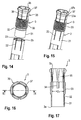
- the assembly of the second sleeve 2 and the interlocking bushing 3 is shown in Figs. 14 and 15 .
- the interlocking bushing is pushed with its cylindrical portion 31 into the first section 21 of the second sleeve 2 until the annular projection 23 snaps into the groove 32.
- the interlocking bushing 3 is coupled to the second sleeve 2 in such a manner, that a rotational motion of the interlocking bushing 3 relative to the second sleeve 2 is possible.
- An axial movement of the interlocking bushing 3 relative to the second sleeve 2 is inhibited when the interlocking bushing abuts against the stop 21 a provided in the second sleeve 2.
- the connection between the second sleeve 2 and the first sleeve 1 via the interlocking bushing 3 is a rigid connection.
- the assembly comprising the second sleeve 2 and the interlocking bushing 3 in a mounted state as shown in Fig. 15 is then inserted into the first sleeve 1 from the rear end 1b until the threaded portion 33 of the interlocking bushing 3 engages the threaded section 14 of the first sleeve 1.
- the legs 25a, 25b are guided in the guiding recesses 19a, 19b in the first sleeve.
- a release or decoupling instrument 50 comprises an inner first portion 51 and an outer portion 52 that slidably receives the inner portion 51.
- the outer portion 52 may be expandable and serves for decoupling the first sleeve 1 from the receiving part 200. It has an outer diameter D 1 so that the outer portion 52 can be guided through the interlocking bushing 3 into the first sleeve 1 and can be spread there. Thereby, the first sleeve 1 can be decoupled from the receiving part.
- the decoupling instrument 50 can be inserted into the interlocking bushing 3 only, if the collet portion 35 is in the second configuration, where it protrudes outward of the second portion 12 into the first portion 11 of the first sleeve 1. Because the first portion 11 has a greater inner diameter than the second portion 12, the collet portion 35 can expand therein so that the inner diameter is sufficiently large to allow insertion of the decoupling instrument 50.
- the third sleeve 4 has a first or front end 4a and a second or rear end 4b. Its outer diameter is preferably greater than the outer diameter of the first sleeve 1. Adjacent to its rear end 4b it comprises two opposite longitudinal slits 41 a, 41b that extend from the second end 4b along at least a portion of the third sleeve that may be up to 1/2 of the length of the third sleeve.
- each longitudinal slit 41a, 41b comprises a wavy structure for latching with a reduction sleeve (not shown) used for further steps in the surgical procedure, for example for pressing down the rod and inserting a locking screw to fix the rod.
- an engagement structure 42 for example, a plurality of flat engagement portions, is provided at an outer surface of an upper portion of the third sleeve for applying a tool thereto.
- the third sleeve 4 has a first inner portion 43 adjacent to the rear end 4b and a second inner portion 44 adjacent to the lower end 4a.
- the second inner portion 44 is configured to accommodate the upper portion of the first sleeve 1 therein.
- the inner diameter of the second section 44 is slightly larger than the outer diameter of the upper end of the first sleeve 1.
- An upper end of the second portion 44 may provide a shoulder 44a, 44b that forms an abutment for the rear end 1b of the first sleeve.
- the shoulder may have an interruption at positions 45a, 45b that correspond to the small protrusions 11a, 11b of the first sleeve.
- An inner diameter of the first portion 43 may be larger than an inner diameter of the second portion 44.
- two transverse slots 46a, 46b are provided at positions that are 180° offset from each other.
- the slots 46a, 46b are configured to accommodate an operating pusher 47 therein.
- the slots 46a, 46b are elongate in a circumferential direction and preferably positioned at 90° with respect to the longitudinal slits 41a, 41b.
- the pusher 47 is a flat piece that can extend through the slots 46a, 46b. It has two substantially parallel longitudinal outer walls 47a, 47b and two outwardly curved sidewalls 47c, 47d that connect the parallel longitudinal sidewalls 47a, 47b, respectively. A total length from the outer end of one curved sidewall 47c to the opposite curved sidewall 47b is greater than the outer diameter of the third sleeve 4 at the position of the transverse slots 46a, 46b, so that a portion of the pusher 47 protrudes outward when the pusher is inserted into the slots 46a, 46b of the third sleeve 4.
- the inside of the pusher is hollow to accommodate the upper portion of the first sleeve 1 therein.
- the pusher 47 has a first inner portion 146 with an inner contour that matches an outer contour of the upper portion of the first sleeve 1 and adjacent thereto a second inner portion 147 with an inner contour greater than an outer contour of the first sleeve 1.
- a recess 148 for accommodating a spring 249 is provided at an inner side of the curved outer sidewall 47c . Furthermore, on one of the substantially flat long sides 47a, 47b, preferably near the other curved sidewall 47d, an elongate hole 149 is provided that is elongate in the lengthwise direction in which the pusher 47 can be moved.
- a securing element 149a such as a headless screw, extends through the wall of the third sleeve 4 into the elongate recess 149 and limits the path of movement of the pusher 47 relative to the third sleeve 4 and prevents loss of the pusher 47.
- the spring 249 that may be a helical spring as shown or any other kind of spring, is positioned in the recess 148 of the pusher 47 and extends into a counter-sink 49a in the abutment plate 49.
- the spring 249 is biased such, that it holds the pusher 47 in a position in which one curved sidewall 47c protrudes outward from the transverse slot 46a and the opposite curved sidewall 47d is within the opposite slot 46b. In this position, the portion 147 that has the larger inner diameter of the pusher 47 is partially narrowed by the third sleeve 4, as can be seen in Fig. 21 .
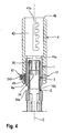
- the first sleeve 1 fits into the portion 44 of the third sleeve 4 and is held via the pusher 47 by means of friction, as can be also seen in Fig. 4 .
- the pusher 47 that protrudes outward from the slot 46a is pushed against the spring force into the slot 46a so that the opposite curved outer wall 47d protrudes from the opposite slot 46b.
- the inner section 147 that has a larger diameter than the upper portion of the first sleeve 1 is brought into a position around the first sleeve 1. In this position, the third sleeve 4 can be removed by pulling the third sleeve 4 from the first sleeve 1.
- the mounting of the third sleeve 4 onto the first sleeve 1 is carried out in a similar manner by pushing the pusher 47 into the slot 46a and placing the third sleeve 4 out the first sleeve.
- the parts of the extension device are all made of a body-compatible material, such as titanium or stainless steel, a body-compatible metal alloy, for example Ti-Ni-alloy, such as Nitinol, or a body-compatible plastic material, such as PEEK.
- the parts may be all of the same or of different materials.
- the extension device is moved with the front end 1a of the first sleeve 1 toward the receiving part 200. Then, the legs 18a, 18b of the first sleeve 1 are spread to a certain extent when they touch the top end 200a of the receiving part 200 and by further downward movement of the extension device, the circumferential projections 120a, 120b of the legs 18a, 18b snap into the circumferential grooves 206a, 206b. Also, the vertical ribs 112a, 112b engage the corresponding vertical grooves 212a, 212b of the receiving part 200.
- the second sleeve 2 is in a retracted position, in which the collet portion 35 extends into the first portion 11 of the first sleeve 1.
- This configuration is shown in Figs. 23a to 24b .
- the thickened upper edge 37 of the collet portion 35 protrudes out of the second portion 12 of the first sleeve so that an inner diameter of the collet portion 35 is at least a diameter >D 1 corresponding to an inner diameter of the threaded portion 33 of the interlocking bushing 3.
- the second sleeve 2 is moved relative to the first sleeve 1 towards the receiving part 200 by screwing the interlocking bushing 3 further towards the front end 1a of the first sleeve 1.
- the projection 27a, 27b of the second sleeve 2 enter the corresponding recesses 207a, 207b at the top end 200a of the receiving part 200, a rotational movement of the second sleeve 2 relative to the first sleeve 1 and therefore also relative to the receiving part 200 is inhibited.
- the tapered upper thickened portion 37 of the collet portion 35 slides along the shoulder formed by the transition between the first portion 11 and the second portion 12 of the first sleeve 1 until it enters the second portion 12.
- the collet portion 35 is radially compressed as shown in Fig. 25b .
- An upper inner diameter of the collet portion is now D 2 .
- the second sleeve 2 can rotate relative to the bushing 3, so that the alignment between the legs 18a, 18b of the first sleeve 1 and the legs 25a, 25b of the second sleeve 2 is maintained.
- a further rotation of the interlocking bushing 3 presses the flat surface portions 26a, 26b of the front end 2a of the second sleeve 2 onto the free flat end surfaces of the receiving part 200.
- the first sleeve 1 is interlocked with the receiving part 200 and with the second sleeve 2 to provide a safe and strong connection between the extension device and the receiving part.
- the insertion of the rod and the locking screw can take place as well as surgical steps thereafter such as compression and distraction steps using the extension device.
- the decoupling instrument that comprises an outer diameter D 1 cannot be inserted in the configuration shown in Fig. 25b .
- the collet portion 35 acts as a locking member that prevents the decoupling of the extension device when the second sleeve 2 is coupled to the receiving part. This enhances the safety of the procedure and prevents damage of portions of the extension device, in particular of the inner sleeve 2.
- the extension device is attached to a receiving part 200 of a bone anchor.
- the whole bone anchor is inserted through a minimally invasive procedure into a pedicle of a vertebra.
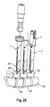
- Exemplary, three vertebrae 501, 502, 503 are shown with bone anchors and mounted extension devices.
- the channels 204 of the receiving parts of the bone anchors can be aligned to permit the insertion of a rod. Because the connection between the receiving part 200 and the extension device is robust and safe, an easy alignment using the extension devices is possible.
- the rod is inserted through the slits 17a, 17b of the extension devices (not shown) and fixed with a locking screw that is guided through the extension device until it can be screwed between the legs 205a, 205b of the receiving part.
- a compression or distraction procedure can be performed using a minimally invasive technique.
- the third sleeve 4 may be used in cases in which the surgeon has to approximate the rod.
- the shape of the engaging complementary structures of the first sleeve and the receiving part as well as the second sleeve and the receiving part can be modified and are not limited to the exact shape shown in the embodiments.
- the second sleeve may be coupled to the receiving part by only a frictional engagement of a portion of the second sleeve and a portion of the receiving part. For example, a front end surface of the second sleeve may be pressed against a free end surface of the legs 205a, 205b of the receiving part.
- the first sleeve may be coupled to the receiving part by such a friction-fit.
- the function of the first and the second sleeve may be interchanged.
- the locking member inhibits the decoupling of the second sleeve when the first sleeve is still coupled to the receiving part.
- the extension device can be used with any bone anchor that comprises a receiving part, such as a polyaxial bone anchor, a monoaxial bone anchor and can also be used with different shapes of receiving parts.
- a receiving part such as a polyaxial bone anchor, a monoaxial bone anchor
- Anchors with inner compression members or outer rings may be used.
- the only necessity is an engagement structure at the receiving part that can cooperate with a corresponding engagement structure of the extension device.
- the locking member in the form of a collet portion is shown as a monolithic part of the interlocking bushing.
- a locking member can also be a separate member, for example a separate collet.
- Other kinds of locking members that can be actuated by actuating the second sleeve, may also be conceivable.
Abstract
an anchoring section (100) for anchoring in a bone and
a receiving part (200) connected to the anchoring section, the receiving part comprising a central axis (C) and a channel (204) for receiving a rod, wherein sidewalls of the channel form two free legs (205a, 205b),
the extension device comprising
a first sleeve (1) with a first sleeve axis (c) that is coaxial to the central axis (C), wherein the first sleeve (1) is configured to be coupled to the receiving part (200) and decoupled from the receiving part (200);
a second sleeve (2) with a second sleeve axis (c) coaxial to the central axis (C), wherein the second sleeve (2) is positioned within the first sleeve (1) and positionable relative to the first sleeve along the central axis (C) and wherein the second sleeve (2) is configured to be coupled to the receiving part (200) and decoupled from the receiving part (200);
a locking member (35) that in a first configuration inhibits decoupling of one of the first sleeve (1) or the second sleeve (2) from the receiving part (200) when the other one of the first sleeve (1) or the second sleeve (2) is still coupled to the receiving part.
Description
- The invention relates to an extension device for a bone anchor, in particular for use in minimally invasive surgery (MIS). The invention also relates to a system including such an extension device and a bone anchor, wherein the bone anchor comprises an anchoring section and a receiving part for receiving a rod to couple the rod to the anchoring section. The extension device includes a first sleeve and a second sleeve that are each configured to be coupled to the receiving part in such a manner that a translational and a rotational movement of the extension device relative to the receiving part is inhibited. A locking member is provided that guarantees correct decoupling of the sleeves from the receiving part.
- Extension devices, also called head extenders, for pedicle screws for use in minimally invasive surgery are known in the art. For example,
US 7,563,264 B2 describes a spinal stabilization system for a minimally invasive procedure wherein detachable sleeves may be coupled to a collar of a bone anchor to allow for formation of the spinal stabilization system through a small skin incision. The detachable sleeve members may allow for alignment of the collars to facilitate insertion of an elongated member in the collars. A coupling system is provided between the sleeve and the collar that inhibits translational movement of the sleeve relative to the collar. In one embodiment, the sleeve may be coupled to a collar of a bone fastener assembly with movable members that may be threaded into threaded openings in the collar. -
WO 2013/112689 A2 describes a minimally invasive tower access device comprising an elongated outer sleeve that slidably receives an elongated inner sleeve. A lock nut is used to secure the inner sleeve and outer sleeve in a locked mode. - There is still a need for an extension device for a bone anchor that is not only safe during use in the surgical steps, such as compression and distraction, but that is also safe during the step of decoupling from the receiving part.
- It is the object of the invention to provide an improved extension device for a bone anchor, in particular for use in minimally invasive surgery, and a system of such an extension device and a bone anchor that facilitates the surgical steps and improves the safety of the device.
- The object is solved by an extension device according to
claim 1 or claim 2 and by a system according toclaim 14. Further developments are given in the dependent claims. - The extension device is configured to be coupled to the receiving part such that it is locked against translational and rotational movement of the extension device relative to the receiving part. Because translational and rotational movements of the extension device and the receiving part are inhibited, the connection between the extension device and the receiving part is robust. This permits a safe placement of the rod and a set screw for fixing the rod. Surgical steps of adjustment of the spinal stabilization system, such as compression or distraction can be performed using the extension device attached to the receiving part, once the bone anchor has been inserted into the bone. In one embodiment, the coupling between the extension device and the receiving part is effected by a formfit engagement of a portion of the extension device with a portion of the receiving part. In another embodiment, the coupling is effected by a frictional engagement of a portion of the extension device with a portion of the receiving part. The coupling can also be partially a form-fit coupling and partially a friction-fit coupling.
- The extension device comprises a first sleeve and a second sleeve positioned within the first sleeve and an interlocking bushing that connects the second sleeve to the first sleeve and allows a controlled axial movement of the second sleeve relative to the first sleeve. After the extension device has been attached to the receiving part, the first sleeve and the second sleeve can be interlocked with each other and with the receiving part by operating the interlocking bushing in one direction. The interlocking connection between the first sleeve and the second sleeve can be released by operating the interlocking bushing in the opposite direction.
- In one embodiment, a translational movement between the extension device and the receiving part can be inhibited by a form-fit engagement of a circumferential rib that extends at least partially around the longitudinal axis of the device and engages a corresponding circumferential groove. The rib may be provided at the first sleeve and the groove at the receiving part or vice versa.
- In another embodiment, the first sleeve may be coupled to the receiving part by means of a form-fit connection and the second sleeve may be coupled to the receiving part by a friction-fit conection only or vice versa
- Decoupling of the extension device from the receiving part can be carried out only in a prescribed sequence of steps which in one embodiment consists in a first step of decoupling the second sleeve and a second step of decoupling the first sleeve. The correct sequence of steps is guaranteed by the presence of a locking member that, in a first configuration, inhibits the decoupling of the first sleeve when the second sleeve is still coupled to the receiving part. When the locking member is in a second configuration after decoupling the second sleeve, the decoupling of the first sleeve is allowed. Hence, a damage of the extension device based on erroneous operation is prevented. Moreover, with the use of such an extension device the surgeon can perform a next step in the surgical procedure only after correct decoupling of the extension device. This enhances the safety of the procedure.
- The extension device may comprise a third sleeve that can be removably connected to the first sleeve in order to provide an extension device having an increased length. For example, a surgical procedure may be started with the longer extension device that comprises the third sleeve attached to the first sleeve for placement of the rod and the set screw. Thereafter, the third sleeve may be removed in order to improve the placement of the receiving part relative to the rod during compression and distraction steps. With the shorter extension device a greater variety of angles of the receiving parts relative to each other may be obtained.
- The extension device comprises only few parts which facilitate the assembly and operation of the device.
- The extension device may be used together with a release or decoupling instrument that is adapted to engage the extension device. The locking member of the extension device is configured to be engaged by the decoupling instrument in its second configuration only. It cannot be engaged in the first configuration in which both, the first and the second sleeve are coupled to the receiving part. Hence, the system of the extension device and the decoupling instrument guarantees the safety of handling and prevents damage of parts of the extension device or the receiving part.
- As the spinal stabilization system includes at least two bone anchors with receiving parts that are adapted to be used with the extension device.
- Further features and advantages of the invention will become apparent from the description of embodiments using the accompanying drawings.
- In the drawings:
- Fig. 1
- shows a perspective exploded view of the extension device according to a first embodiment.
- Fig. 2
- shows a perspective partially exploded view of the extension device of
Fig. 1 in an assembled state with an optional third sleeve. - Fig. 3
- shows a perspective view of the extension device of
Fig. 2 in an assembled state. - Fig. 4
- shows a cross-sectional view of an upper portion of the extension device of
Figs. 2 and 3 with the attached third sleeve, wherein the cross-section is taken in a plane including the sleeve axis. - Fig. 5
- shows a perspective view of an embodiment of a receiving part of a bone anchor that may form together with the extension device of
Figs. 1 to 4 a first embodiment of a system of an extension device and a bone anchor. - Fig. 6
- shows a top view of the receiving part of
Fig. 5 . - Fig. 7a
- shows a cross-sectional view of the receiving part of
Fig. 5 and Fig. 6 along the lines A-A' inFig. 6 . - Fig. 7b
- shows an enlarged view of a detail of
Fig. 7a . - Fig. 8a
- shows a perspective view of a first sleeve of the extension device of
Figs. 1 to 4 . - Fig. 8b
- shows a perspective view from the bottom of a front end portion of the first sleeve of
Fig. 8a . - Fig. 9
- shows a top view of the first sleeve of
Fig. 8a . - Fig. 10
- shows a cross-sectional view of the first sleeve of
Fig. 8a along line B-B inFig. 9 . - Fig. 11
- shows a cross-sectional view of the first sleeve of
Fig. 8a along line D-D inFig. 10 . - Fig. 12a
- shows a perspective view of a second sleeve of the extension device of
Figs. 1 to 4 . - Fig. 12b
- shows an enlarged perspective view from the bottom of a front end portion of the second sleeve of
Fig. 12a . - Fig. 13
- shows a cross-sectional view of the second sleeve according to
Fig. 12a , the cross-section taken in a plane containing the sleeve axis and extending through the center of the legs of the sleeve. - Fig. 14
- shows an exploded perspective view of an interlocking bushing of the extension device of
Figs. 1 and 2 and an end portion of the second sleeve. - Fig. 15
- shows a perspective view of the interlocking bushing and the end portion of the second sleeve of
Fig. 14 in an assembled state. - Fig. 16
- shows a top view of the interlocking bushing of
Fig. 14 . - Fig. 17
- shows a cross-sectional view of the interlocking bushing of
Fig. 14 along line E-E inFig. 16 . - Fig. 18
- shows a perspective view of a bone anchor with a receiving part and a front portion of the extension device according to the first embodiment coupled to the receiving part.
- Fig. 19
- shows a cross-sectional view of an upper portion of the extension device, without third sleeve, and a front end portion of a decoupling instrument to be used with and adapted to the extension device, the cross-section taken in a plane including the sleeve axis.
- Fig. 20
- shows a perspective exploded view of the third sleeve.
- Fig. 21
- shows a top view of the third sleeve shown in
Fig. 20 . - Fig. 22
- shows a cross-sectional view of the third sleeve of
Figs. 20 and 21 along line F-F inFig. 21 . - Fig. 23a
- shows a cross-sectional view of a first step of coupling the extension device to the receiving part of a bone anchor.
- Fig. 23b
- shows a cross-sectional view of an upper portion of the extension device in the first step according to
Fig. 23a , wherein the interlocking bushing is in a second configuration. - Fig. 24a
- shows a cross-sectional view of a second step of coupling the extension device to the receiving part of a bone anchor.
- Fig. 24b
- shows a cross-sectional view of an upper portion of the extension device in the step of
Fig. 24a , wherein the interlocking bushing is still in the second configuration. - Fig. 25a
- shows a cross-sectional view of a third step of coupling the extension device to the receiving part of a bone anchor.
- Fig. 25b
- shows a cross-sectional view of an upper portion of the extension device in the step of
Fig. 25a , wherein the interlocking bushing is in a first configuration. - Fig. 26
- shows a perspective view of a system comprising at least two bone anchors with a receiving part and extension devices with different length coupled thereto.
- As shown in
Figs. 1 to 3 , an extension device according to a first embodiment includes afirst sleeve 1 that forms an outer sleeve, asecond sleeve 2 that forms an inner sleeve and that is positionable within thefirst sleeve 1 and an interlockingbushing 3. The interlockingbushing 3 is configured to be connected to thesecond sleeve 2 and is configured to couple thesecond sleeve 2 to thefirst sleeve 1 such as to permit a controlled motion of thesecond sleeve 2 relative to thefirst sleeve 1. In addition, athird sleeve 4 may be included in the extension device. Thethird sleeve 4 can be removably attached to thefirst sleeve 1 to extend the length of thefirst sleeve 1. When thefirst sleeve 1 and thesecond sleeve 2 are assembled as shown inFigs. 2 and 3 , the extension device can be used to place the parts of a spinal stabilization system in a patient's body using a minimally invasive procedure. For some particular steps in the surgical procedure, thethird sleeve 4 may be removed. - The extension device shown in
Figs. 1 to 3 is configured to be used with a bone anchor for example with a pedicle screw. As depicted inFigs. 5 to 7b and23a to 25b , an example of such a bone anchor may comprise an anchoring element with a threadedshank 100 and a spherical segment-shapedhead 101, wherein the anchoring element is pivotably coupled to a receivingpart 200. The receiving part is shown in more detail inFigs. 5 to 7b . Typically, the receiving part may be formed as a substantially cylindrical part with a first end ortop end 200a and a second end orbottom end 200b, a central axis C, acoaxial bore 201 extending from thetop end 200a to a distance from thebottom end 200b, and aseat 202 for thehead 101 of the anchoring element as well as alower opening 203 at thebottom end 200b where the shank of the bone anchoring element can pass through. A substantiallyU-shaped recess 204 may extend from thetop end 200a in the direction of thebottom end 200b. Therecess 204 serves for receiving a rod (not shown) therein. By means of therecess 204 twofree legs legs top end 200a, circumferentially extendinggrooves U-shaped recess 204 to the other end and that are open towards theU-shaped recess 204. Anupper sidewall 206a', 206b' and alower sidewall 206a", 206b" of thegroove bottom end 200b. - The receiving
part 200 may further include at thetop end 200a in a free end surface of each of thelegs recess recess recesses 207a; 207b serve for engagement with a portion of the extension device as described below. There may be a chamferedsection 208 provided at the top end of eachrecess recess - In addition, the receiving
part 200 may comprise a pair oflongitudinal grooves 212a at one side of theU-shaped recess 204 and a pair oflongitudinal grooves 212b at the opposite side. The grooves of each pair ofgrooves top end 200a in the outer wall of the receiving part on either side of therecesses top end 200a. The grooves may have a decreasing depth towards their closed end that is located at a distance from thetop end 200a. The cross-section of thelongitudinal grooves Fig. 5 , thelongitudinal grooves circumferentially extending grooves grooves - In an upper portion of the
legs internal thread 209 may be provided for cooperating with a locking screw (not shown) for fixing the rod. - Referring to
Figs. 8a to 10 , thefirst sleeve 1 of the extension device is elongate and comprises a longitudinal axis c that is coaxial with the central axis C of the receivingpart 200 when the extension device is coupled to the receiving part. Thefirst sleeve 1 further has afront end 1a and arear end 1b. - Adjacent to the
rear end 1b, afirst section 11 is provided with an inner diameter that is greater than an inner diameter of a followingsecond section 12. Twosmall projections rear end 1b. They may interact with recesses in thethird sleeve 4 for correct positioning of thethird sleeve 4 onto thefirst sleeve 1. Thesecond section 12 that follows thefirst section 11 serves the function of providing a clamping portion for the interlockingbushing 3 as described below. Adjacent to thesecond section 12, athird section 13 follows that may have a slightly smaller inner diameter compared to thesecond section 12. In thethird section 13, an internal thread 15 is provided that is configured to interact with the interlockingbushing 3. The internally threaded section 15 is preferably adjacent to thesecond section 12. Thefirst sleeve 1 may be in a portion thereof at 90° offset from theprojections longitudinal recesses - The
first sleeve 1 may further comprise in its outer wall at a first distance from therear end 1b two opposite firsttransverse recesses first sleeve 1. Therecesses small projections rear end 1b twosecond recesses recesses transverse recesses first sleeve 1 and may serve for cleaning purposes to provide access to therecesses - Two elongate substantially
U-shaped slits slit 204 in the receiving part and that are offset from each other by 180° extend from thefront end 1a towards therear end 1b up to a distance from thesecond section 12 of thefirst sleeve 1. Thelongitudinal slits slits part 200. The length of theslits first recesses slits free legs free legs part 200. By means of thelegs first sleeve 1 is slightly flexible in a direction perpendicular to the sleeve axis, so that thefirst sleeve 1 can be snapped onto thelegs part 200. - The inner surface of the
third section 13 of thefirst sleeve 1 comprises at each of thelegs guiding recess second sleeve 2 can extend to be guided therein. The guiding recesses 19a, 19b extend in a longitudinal direction beyond theslits rear end 1b, as can be seen in particular inFig. 10 . - Each of the
legs front end 1a an inwardly directedprojection slit 17a to theopposite slit 17b. The shape of thecircumferential projection circumferential grooves part 200, as can be seen in particular inFigs. 18 or24a, 25a . - An upper surface of the
projections rear end 1b, may be inclined towards the rear end to match the complementary inclinedupper wall 206a', 206b' of thegroove circumferential projections rear end 1b. The inclination facilitates the engagement of theprojections groove first sleeve 1 is coupled to the receivingpart 200. - In addition, the
first sleeve 1 comprises at positions that correspond in a circumferential direction to the positions of thelongitudinal grooves part 200, a pair ofribs 112a, and a pair ofribs 112b on thelegs ribs legs front end 1a and have a shape that substantially matches the shape of thegrooves Fig. 8b , an outer surface of theribs - From each of the
longitudinal ribs rib portion 123a, 123b extends outward in a circumferential direction. Thistransverse rib portion 123a, 123b is located at a distance from thefront end 1a that corresponds to the distance of thecircumferentially extending groove top end 200a. Hence, thetransverse rib portion 123a, 123b is at the same level as thecircumferential projections - By means of the
longitudinal ribs longitudinal grooves - An overall outer shape of the
first sleeve 1 may be cylindrical. Flattenedouter surface portion legs - The total length of the first sleeve is such that when the bone anchor is inserted into the bone and the
first sleeve 1 is attached to the receivingpart 200, the extension device protrudes to a sufficient extent from the operation site. - As illustrated in
Figs. 12a to 13 , thesecond sleeve 2 comprises afront end 2a and an oppositerear end 2b. Thesecond sleeve 12 has a substantially constant outer diameter. Adjacent to therear end 2b, thesecond sleeve 2 comprises afirst portion 21 with a circumferentially closed cylinder surface. Thefirst portion 21 is configured to engage the interlockingbushing 3. A plurality oflongitudinal slits 22 that are open to therear end 2b and extend up to a distance from therear end 2b, are provided to render thefirst portion 21 flexible in such a way that thefirst portion 21 can elastically snap onto a portion of the interlockingbushing 3 and is held there by friction. At a first distance from therear end 2b an inwardly extendingannular projection 23, is provided. Theannular projection 23 interacts with a corresponding depression or a groove at the interlockingbushing 3 to inhibit an inadvertent removal of the interlockingbushing 3 from thesecond sleeve 2. At a second distance from therear end 2b that is greater than the first distance, astop 21a, for example in the form of an annular shoulder, is provided. Theshoulder 21a limits the insertion of the interlocking bushing into thesecond sleeve 2 and forms an abutment when the interlocking bushing is screwed downward into thefirst sleeve 1. An outer diameter of thefirst section 21 of thesecond sleeve 2 is smaller than an inner diameter of thethird section 13 of thefirst sleeve 1. - Two
recesses 24a, 24b with a substantially rectangular cross-section extend from thefront end 2a through thesecond sleeve 2 up to thefirst portion 21. Therecesses 24a, 24b have such a size that twoopposite legs recesses first sleeve 1. Thelegs recesses first sleeve 1 in a direction towards therear end 1b of thefirst sleeve 1. - The
front end 2a of thesecond sleeve 2 is comprised of a substantially flat surface portion 26a, 26b on each of thelegs top end 200a of the receiving part. Moreover, aprojections recess part 200 is provided. Hence, theprojection recess projections legs projections legs projections recesses projections legs - Turning now to
Figs. 14 to 17 , the interlockingbushing 3 comprises afront end 3a and arear end 3b, acylindrical section 31 adjacent to thefront end 3a and that has an outer diameter substantially equal to an inner diameter of thefirst section 21 of thesecond sleeve 2 so that thebushing 3 is held in thesecond sleeve 2 by friction. Adjacent to thecylindrical section 31 with a smooth outer surface, there is agroove 32 that interacts with theannular projection 23 of thesecond sleeve 2. Following thegroove 32 there is a threadedportion 33 with an external thread that is configured to interact with the threadedsection 14 of thefirst sleeve 1. - The interlocking
bushing 3 has an inner diameter in the threadedportion 33 that is slightly larger than D1 wherein D1 corresponds to an outer diameter of a decoupling instrument. A plurality oflongitudinal engagement grooves 34 for a driver are provided in the inner wall of the interlockingbushing 3 at an upper region of the threadedportion 33. Adjacent to therear end 3b, there is acollet portion 35 that is characterized by a plurality of substantiallylongitudinal slits 36 that are open towards therear end 3b. Theslits 36 render thecollet portion 35 flexible, such that it can be radially compressed by exerting pressure from the outside. Thecollet portion 35 comprises at therear end 3b of the interlocking bushing a thickenedannular portion 37 that has alower side 37a that tapers toward the sleeve axis and anupper side 37b that inversely tapers toward the sleeve axis so that a cross-section of the thickenedportion 37 is substantially triangular. The length of thecollet portion 35 is such that when the interlockingbushing 3 is screwed into thefirst sleeve 1 and thesecond sleeve 2 engages the receivingpart 200, most part of the thickenedportion 37 of thecollet portion 35 is located within thesecond portion 12 of thefirst sleeve 1, as depicted more in detail inFig. 19 . In this position, thecollet portion 35 is slightly compressed by the inner wall of thefirst sleeve 1 so that an inner diameter D2 of thecollet portion 35 is smaller than D1 as shown in detail inFig. 19 . When the interlockingbushing 3 is screwed backward thecollet portion 35 emerges from thesecond portion 12 whereby it expands. - Hence, the
collet portion 35 forms a locking member that can assume a first configuration in which it is compressed and inhibits the insertion of a tool that removes thefirst sleeve 1 from the receiving part as long as thesecond sleeve 2 is still engaging the receiving part and that can assume a second configuration in which it is expanded and allows the insertion of the tool when thesecond sleeve 2 is decoupled. In this embodiment, the locking member is monolithically formed with the interlockingbushing 3. - The assembly of the
second sleeve 2 and the interlockingbushing 3 is shown inFigs. 14 and 15 . The interlocking bushing is pushed with itscylindrical portion 31 into thefirst section 21 of thesecond sleeve 2 until theannular projection 23 snaps into thegroove 32. By means of this, the interlockingbushing 3 is coupled to thesecond sleeve 2 in such a manner, that a rotational motion of the interlockingbushing 3 relative to thesecond sleeve 2 is possible. An axial movement of the interlockingbushing 3 relative to thesecond sleeve 2 is inhibited when the interlocking bushing abuts against thestop 21 a provided in thesecond sleeve 2. The connection between thesecond sleeve 2 and thefirst sleeve 1 via the interlockingbushing 3 is a rigid connection. - The assembly comprising the
second sleeve 2 and the interlockingbushing 3 in a mounted state as shown inFig. 15 is then inserted into thefirst sleeve 1 from therear end 1b until the threadedportion 33 of the interlockingbushing 3 engages the threadedsection 14 of thefirst sleeve 1. Thelegs recesses - As depicted in
Fig. 19 , a release ordecoupling instrument 50, only a front portion of which is shown, comprises an innerfirst portion 51 and anouter portion 52 that slidably receives theinner portion 51. Theouter portion 52 may be expandable and serves for decoupling thefirst sleeve 1 from the receivingpart 200. It has an outer diameter D1 so that theouter portion 52 can be guided through the interlockingbushing 3 into thefirst sleeve 1 and can be spread there. Thereby, thefirst sleeve 1 can be decoupled from the receiving part. - The
decoupling instrument 50 can be inserted into the interlockingbushing 3 only, if thecollet portion 35 is in the second configuration, where it protrudes outward of thesecond portion 12 into thefirst portion 11 of thefirst sleeve 1. Because thefirst portion 11 has a greater inner diameter than thesecond portion 12, thecollet portion 35 can expand therein so that the inner diameter is sufficiently large to allow insertion of thedecoupling instrument 50. - Referring to
Figs. 20 to 22 , the optionalthird sleeve 4 will be described. Thethird sleeve 4 has a first orfront end 4a and a second orrear end 4b. Its outer diameter is preferably greater than the outer diameter of thefirst sleeve 1. Adjacent to itsrear end 4b it comprises two oppositelongitudinal slits second end 4b along at least a portion of the third sleeve that may be up to 1/2 of the length of the third sleeve. One of the sidewalls of eachlongitudinal slit engagement structure 42, for example, a plurality of flat engagement portions, is provided at an outer surface of an upper portion of the third sleeve for applying a tool thereto. - The
third sleeve 4 has a firstinner portion 43 adjacent to therear end 4b and a secondinner portion 44 adjacent to thelower end 4a. The secondinner portion 44 is configured to accommodate the upper portion of thefirst sleeve 1 therein. For this purpose, the inner diameter of thesecond section 44 is slightly larger than the outer diameter of the upper end of thefirst sleeve 1. An upper end of thesecond portion 44 may provide ashoulder 44a, 44b that forms an abutment for therear end 1b of the first sleeve. The shoulder may have an interruption atpositions 45a, 45b that correspond to thesmall protrusions first portion 43 may be larger than an inner diameter of thesecond portion 44. - At a distance from the
lower end 4a twotransverse slots slots operating pusher 47 therein. Theslots longitudinal slits second section 44, there is at the bottom of one of the elongatetransverse slots 46a a substantiallyrectangular recess 48 that serves for accommodating anabutment plate 49 therein. - The
pusher 47 is a flat piece that can extend through theslots outer walls curved sidewalls longitudinal sidewalls curved sidewall 47c to the oppositecurved sidewall 47b is greater than the outer diameter of thethird sleeve 4 at the position of thetransverse slots pusher 47 protrudes outward when the pusher is inserted into theslots third sleeve 4. The inside of the pusher is hollow to accommodate the upper portion of thefirst sleeve 1 therein. More in detail, thepusher 47 has a firstinner portion 146 with an inner contour that matches an outer contour of the upper portion of thefirst sleeve 1 and adjacent thereto a secondinner portion 147 with an inner contour greater than an outer contour of thefirst sleeve 1. - At an inner side of the curved
outer sidewall 47c arecess 148 for accommodating aspring 249 is provided. Furthermore, on one of the substantially flatlong sides curved sidewall 47d, anelongate hole 149 is provided that is elongate in the lengthwise direction in which thepusher 47 can be moved. A securingelement 149a, such as a headless screw, extends through the wall of thethird sleeve 4 into theelongate recess 149 and limits the path of movement of thepusher 47 relative to thethird sleeve 4 and prevents loss of thepusher 47. - The
spring 249, that may be a helical spring as shown or any other kind of spring, is positioned in therecess 148 of thepusher 47 and extends into a counter-sink 49a in theabutment plate 49. Thespring 249 is biased such, that it holds thepusher 47 in a position in which onecurved sidewall 47c protrudes outward from thetransverse slot 46a and the oppositecurved sidewall 47d is within theopposite slot 46b. In this position, theportion 147 that has the larger inner diameter of thepusher 47 is partially narrowed by thethird sleeve 4, as can be seen inFig. 21 . Hence, in this position, thefirst sleeve 1 fits into theportion 44 of thethird sleeve 4 and is held via thepusher 47 by means of friction, as can be also seen inFig. 4 . To remove thethird sleeve 4 from thefirst sleeve 1, thepusher 47 that protrudes outward from theslot 46a, is pushed against the spring force into theslot 46a so that the opposite curvedouter wall 47d protrudes from theopposite slot 46b. By means of this, theinner section 147 that has a larger diameter than the upper portion of thefirst sleeve 1 is brought into a position around thefirst sleeve 1. In this position, thethird sleeve 4 can be removed by pulling thethird sleeve 4 from thefirst sleeve 1. - The mounting of the
third sleeve 4 onto thefirst sleeve 1 is carried out in a similar manner by pushing thepusher 47 into theslot 46a and placing thethird sleeve 4 out the first sleeve. - The parts of the extension device are all made of a body-compatible material, such as titanium or stainless steel, a body-compatible metal alloy, for example Ti-Ni-alloy, such as Nitinol, or a body-compatible plastic material, such as PEEK. The parts may be all of the same or of different materials.
- Referring now to
Figs. 18 to 25b , the attachment of the extension device to a bone anchor will be described. As shown inFig. 23a , the extension device is moved with thefront end 1a of thefirst sleeve 1 toward the receivingpart 200. Then, thelegs first sleeve 1 are spread to a certain extent when they touch thetop end 200a of the receivingpart 200 and by further downward movement of the extension device, thecircumferential projections legs circumferential grooves vertical ribs vertical grooves part 200. During coupling of thefirst sleeve 1, thesecond sleeve 2 is in a retracted position, in which thecollet portion 35 extends into thefirst portion 11 of thefirst sleeve 1. This configuration is shown inFigs. 23a to 24b . The thickenedupper edge 37 of thecollet portion 35 protrudes out of thesecond portion 12 of the first sleeve so that an inner diameter of thecollet portion 35 is at least a diameter >D1 corresponding to an inner diameter of the threadedportion 33 of the interlockingbushing 3. - Then, as shown in
Figs. 25a and 25b , thesecond sleeve 2 is moved relative to thefirst sleeve 1 towards the receivingpart 200 by screwing the interlockingbushing 3 further towards thefront end 1a of thefirst sleeve 1. When theprojection second sleeve 2 enter the correspondingrecesses top end 200a of the receivingpart 200, a rotational movement of thesecond sleeve 2 relative to thefirst sleeve 1 and therefore also relative to the receivingpart 200 is inhibited. At the same time, the tapered upper thickenedportion 37 of thecollet portion 35 slides along the shoulder formed by the transition between thefirst portion 11 and thesecond portion 12 of thefirst sleeve 1 until it enters thesecond portion 12. Thereby, thecollet portion 35 is radially compressed as shown inFig. 25b . An upper inner diameter of the collet portion is now D2. Thesecond sleeve 2 can rotate relative to thebushing 3, so that the alignment between thelegs first sleeve 1 and thelegs second sleeve 2 is maintained. A further rotation of the interlockingbushing 3 presses the flat surface portions 26a, 26b of thefront end 2a of thesecond sleeve 2 onto the free flat end surfaces of the receivingpart 200. Thereby and by the engagement of theprojections first sleeve 1 in thegrooves second sleeve 2 thefirst sleeve 1 is interlocked with the receivingpart 200 and with thesecond sleeve 2 to provide a safe and strong connection between the extension device and the receiving part. In such a configuration, the insertion of the rod and the locking screw can take place as well as surgical steps thereafter such as compression and distraction steps using the extension device. - The decoupling instrument that comprises an outer diameter D1 cannot be inserted in the configuration shown in
Fig. 25b . Hence, thecollet portion 35 acts as a locking member that prevents the decoupling of the extension device when thesecond sleeve 2 is coupled to the receiving part. This enhances the safety of the procedure and prevents damage of portions of the extension device, in particular of theinner sleeve 2. - Turning the interlocking
bushing 3 in the opposite direction, releases the interlocking connection and permits to retract theprojections recesses - In the clinical use, as shown in
Fig. 26 , the extension device is attached to a receivingpart 200 of a bone anchor. The whole bone anchor is inserted through a minimally invasive procedure into a pedicle of a vertebra. Exemplary, threevertebrae channels 204 of the receiving parts of the bone anchors can be aligned to permit the insertion of a rod. Because the connection between the receivingpart 200 and the extension device is robust and safe, an easy alignment using the extension devices is possible. Thereafter, the rod is inserted through theslits legs first sleeve 1 and thesecond sleeve 2 without thethird sleeve 4, has the advantage that the extension devices have a greater distance with respect to each other and that a greater angle between one extension device and another extension device can be achieved. Thethird sleeve 4 may be used in cases in which the surgeon has to approximate the rod. - Modifications of the above described embodiment may be contemplated. It shall be noted, that the shape of the engaging complementary structures of the first sleeve and the receiving part as well as the second sleeve and the receiving part can be modified and are not limited to the exact shape shown in the embodiments. In a further modification, the second sleeve may be coupled to the receiving part by only a frictional engagement of a portion of the second sleeve and a portion of the receiving part. For example, a front end surface of the second sleeve may be pressed against a free end surface of the
legs - The function of the first and the second sleeve may be interchanged. In such a case, the locking member inhibits the decoupling of the second sleeve when the first sleeve is still coupled to the receiving part.
- The extension device can be used with any bone anchor that comprises a receiving part, such as a polyaxial bone anchor, a monoaxial bone anchor and can also be used with different shapes of receiving parts. Anchors with inner compression members or outer rings may be used. The only necessity is an engagement structure at the receiving part that can cooperate with a corresponding engagement structure of the extension device.
- The locking member in the form of a collet portion is shown as a monolithic part of the interlocking bushing. However, a locking member can also be a separate member, for example a separate collet. Other kinds of locking members that can be actuated by actuating the second sleeve, may also be conceivable.
Claims (17)
- An extension device for a bone anchor, wherein the bone anchor comprisesan anchoring section (100) for anchoring in a bone anda receiving part (200) connected to the anchoring section, the receiving part comprising a central axis (C) and a channel (204) for receiving a rod, wherein sidewalls of the channel form two free legs (205a, 205b),the extension device comprising
a first sleeve (1) with a first sleeve axis (c) that is coaxial to the central axis (C), wherein the first sleeve (1) is configured to be coupled to the receiving part (200) and decoupled from the receiving part (200);
a second sleeve (2) with a second sleeve axis (c) coaxial to the central axis (C), wherein the second sleeve (2) is positioned within the first sleeve (1) and positionable relative to the first sleeve along the central axis (C) and wherein the second sleeve (2) is configured to be coupled to the receiving part (200) and decoupled from the receiving part (200);
a locking member (35) that in a first configuration inhibits decoupling of one of the first sleeve (1) or the second sleeve (2) from the receiving part (200) when the other one of the first sleeve (1) or the second sleeve (2) is still coupled to the receiving part. - The extension device of claim 1, wherein in a second configuration the locking member (35) permits decoupling of one of the first sleeve (1) or the second sleeve (2) from the receiving part (200) when the other one of the first sleeve (1) or the second sleeve (2) is already decoupled from the receiving part.
- The extension device of claim 1 or 2, wherein the locking member (35) inhibits decoupling of the first sleeve (1) when the second sleeve (2) is coupled to the receiving part.
- The extension device of one of claims 1 to 3, wherein the locking member (35) is sized and arranged so as to inhibit attachment of a decoupling instrument when the locking member (35) is in the first configuration.
- The extension device of one of claims 1 to 4, wherein the locking member (35) comprises a spring that is compressible and/or extendible in a radial direction relative to the central axis (C).
- The extension device of one of claims 1 to 5, wherein the locking member (35) is formed as a collet that is positioned at least partially inside the second sleeve (2) and that has a first inner diameter (D2) that is smaller than an outer diameter (D1) of a portion of a decoupling instrument (50) when the locking member (35) is in the first configuration.
- The extension device of one of claims 1 to 7, wherein the second sleeve (2) is connected to the first sleeve (1) through a coupling member (3) that is configured to advance together with the second sleeve (2) in an axial direction relative to the first sleeve (1).
- The extension device of claim 7, wherein the coupling member (3) is a bushing that is coupled to the first sleeve (1) through an advancement structure (33, 14) that permits to advance the coupling member with the second sleeve (2) to a given position.
- The extension device of one of claims 7 to 9, wherein the coupling member (3) is coupled to the second sleeve (2) so that it can rotate with respect to the second sleeve.
- The extension device of one of claims 7 to 9, wherein the locking member (35) and the coupling member (3) are formed as a single monolithic part.
- The extension device of one of claims 1 to 10, further comprising a third sleeve (4) that is selectively connectable to the first sleeve (1) to enlarge an axial length of the extension de-vice.
- An extension device for a bone anchor, wherein the bone anchor comprisesan anchoring section (100) for anchoring in a bone anda receiving part (200) connected to the anchoring section, the receiving part comprising a central axis (C) and a channel (204) for receiving a rod, wherein sidewalls of the channel form two free legs (205a, 205b),the extension device comprising
a first sleeve (1) with a first sleeve axis (c) that is coaxial to the central axis (C), wherein the first sleeve (1) is configured to be coupled to the receiving part (200) and decoupled from the receiving part (200);
a second sleeve (2) with a second sleeve axis coaxial to the central axis (C), wherein the second sleeve (2) is positioned within the first sleeve (1) and positionable relative to the first sleeve along the central axis (C) and wherein the second sleeve (2) is configured to be coupled to the receiving part (200) and decoupled from the receiving part (200);
a third sleeve (4) that is selectively connectable to the first sleeve (1) to enlarge an axial length of the extension device - The extension device of claim 12 wherein the third sleeve (4) comprises two opposite slots (46a, 46b) and a pusher (47) extending through the slots (46a, 46b) wherein the pusher (47) comprises an inner hollow section (146, 147) and wherein the first sleeve (1) of the extension device can be clamped inside the third sleeve (4) in a first position of the pusher (47) and can be released in a second position of the pusher (47).
- A system of an extension device according to one of claims 1 to 13 and a bone anchor, wherein the bone anchor comprises
the anchoring section (100) for anchoring in a bone andthe receiving part (200, 200') connected to the anchoring section, the receiving part comprising a central axis (C) and a channel (204) for receiving a rod, wherein sidewalls of the channel form two free legs (205a, 205b) and wherein the receiving part (200) comprises an engagement structure (206a, 206b, 212a, 212b) that can be coupled to a substantially complementary engagement structure (120a, 120b, 112a, 112b) of the extension device. - The system of claim 14, wherein the both, the first sleeve (1) and the second sleeve (2) comprise an engagement structure (120a, 120b, 112a, 112b; 27a, 27b) for a form-fit engagement with a corresponding engagement structure (206a, 206b, 212a, 212b; 207a, 207b) of the receiving part (200).
- The system of claim 14, wherein the first sleeve (1) comprises an engagement structure (120a, 120b, 112a, 112b) for a form-fit engagement with a corresponding engagement structure (206a, 206b, 212a, 212b) of the receiving part and wherein the second sleeve (2) is configured to be coupled to the receiving part(200) via a frictional engagement.
- A spinal stabilization system for use with minimally invasive surgery comprising a system of one of claims 14 to 16 with at least two bone anchors and an extension device for each bone anchor according to one of claims 1 to 13.
Priority Applications (6)
| Application Number | Priority Date | Filing Date | Title |
|---|---|---|---|
| EP14172835.2A EP2957246B1 (en) | 2014-06-17 | 2014-06-17 | Extension device for a bone anchor, in particular for minimally invasive surgery |
| JP2015119057A JP2016002465A (en) | 2014-06-17 | 2015-06-12 | Extension device for bone anchor, system for extension device and spine stabilization system |
| CN201510321345.1A CN105167829B (en) | 2014-06-17 | 2015-06-12 | For being used in particular for the extension apparatus of the bone anchor assembly of Minimally Invasive Surgery |
| TW104118995A TW201600061A (en) | 2014-06-17 | 2015-06-12 | Extension device for a bone anchor, in particular for minimally invasive surgery |
| US14/740,228 US9956012B2 (en) | 2014-06-17 | 2015-06-15 | Extension device for a bone anchor, in particular for minimally invasive surgery |
| KR1020150084441A KR20150144709A (en) | 2014-06-17 | 2015-06-15 | Extension device for a bone anchor, in particular for minimally invasive surgery |
Applications Claiming Priority (1)
| Application Number | Priority Date | Filing Date | Title |
|---|---|---|---|
| EP14172835.2A EP2957246B1 (en) | 2014-06-17 | 2014-06-17 | Extension device for a bone anchor, in particular for minimally invasive surgery |
Publications (2)
| Publication Number | Publication Date |
|---|---|
| EP2957246A1 true EP2957246A1 (en) | 2015-12-23 |
| EP2957246B1 EP2957246B1 (en) | 2017-04-19 |
Family
ID=50943207
Family Applications (1)
| Application Number | Title | Priority Date | Filing Date |
|---|---|---|---|
| EP14172835.2A Active EP2957246B1 (en) | 2014-06-17 | 2014-06-17 | Extension device for a bone anchor, in particular for minimally invasive surgery |
Country Status (6)
| Country | Link |
|---|---|
| US (1) | US9956012B2 (en) |
| EP (1) | EP2957246B1 (en) |
| JP (1) | JP2016002465A (en) |
| KR (1) | KR20150144709A (en) |
| CN (1) | CN105167829B (en) |
| TW (1) | TW201600061A (en) |
Cited By (2)
| Publication number | Priority date | Publication date | Assignee | Title |
|---|---|---|---|---|
| EP4008284A1 (en) * | 2020-12-02 | 2022-06-08 | Biedermann Technologies GmbH & Co. KG | Connection device for use with extension members of a bone anchor |
| WO2024022642A1 (en) * | 2022-07-29 | 2024-02-01 | Taurus Gmbh & Co.Kg | Instrument set and tulip of the same |
Families Citing this family (9)
| Publication number | Priority date | Publication date | Assignee | Title |
|---|---|---|---|---|
| US9370383B2 (en) | 2013-03-15 | 2016-06-21 | Zimmer Biomet Spine, Inc. | Minimally invasive splitable pedicle screw extender |
| FR3018678B1 (en) * | 2014-03-20 | 2016-03-11 | Spineway | SURGICAL ASSEMBLY, BONE ANCHORING SCREW AND DEVICE FOR EXTENSION OF SUCH SCREWS FORMING PART OF SAID SURGICAL ASSEMBLY |
| US9439692B1 (en) * | 2015-10-09 | 2016-09-13 | Spine Wave, Inc. | Minimally invasive spinal fixation system and method therefor |
| US10064662B2 (en) * | 2016-08-12 | 2018-09-04 | Amendia, Inc. | Minimally invasive screw extension assembly |
| USD902405S1 (en) | 2018-02-22 | 2020-11-17 | Stryker Corporation | Self-punching bone anchor inserter |
| US11484350B2 (en) * | 2018-12-13 | 2022-11-01 | Zimmer Biomet Spine, Inc. | Split tower for a bone anchor |
| US11559337B2 (en) | 2018-12-14 | 2023-01-24 | Zimmer Biomet Spine, Inc. | Expended tab reinforcement sleeve |
| US11786277B2 (en) * | 2020-08-12 | 2023-10-17 | Snj Patents, Llc | Tower pedicle screw system |
| DE102022120382A1 (en) * | 2021-08-13 | 2023-02-16 | Zimmer Biomet Spine, Inc. | BONE FIXING TOWER ASSEMBLY FOR SPINE SURGERY |
Citations (7)
| Publication number | Priority date | Publication date | Assignee | Title |
|---|---|---|---|---|
| US20050131408A1 (en) * | 2003-12-16 | 2005-06-16 | Sicvol Christopher W. | Percutaneous access devices and bone anchor assemblies |
| US20080125788A1 (en) * | 2006-09-26 | 2008-05-29 | Cohen Dan S | Percutaneous instrument assembly |
| US7563264B2 (en) | 2002-10-30 | 2009-07-21 | Zimmer Spine Austin, Inc. | Spinal stabilization systems and methods |
| WO2013112689A2 (en) | 2012-01-25 | 2013-08-01 | Spinal Usa, Inc. | Minimally invasive devices and methods for delivering fixation devices and implants into a spine |
| WO2013187928A1 (en) * | 2012-06-14 | 2013-12-19 | Spine Wave, Inc. | Pedicle screw extension for use in percutaneous spinal fixation |
| US20140039567A1 (en) * | 2012-08-01 | 2014-02-06 | Aesculap Ag | Surgical apparatus |
| US20140052187A1 (en) * | 2012-08-17 | 2014-02-20 | Warsaw Orthopedic, Inc. | Spinal implant system and method |
Family Cites Families (13)
| Publication number | Priority date | Publication date | Assignee | Title |
|---|---|---|---|---|
| US7951175B2 (en) * | 2005-03-04 | 2011-05-31 | Depuy Spine, Inc. | Instruments and methods for manipulating a vertebra |
| KR101387163B1 (en) * | 2006-04-11 | 2014-04-29 | 신세스 게엠바하 | Minimally invasive fixation system |
| US7918857B2 (en) * | 2006-09-26 | 2011-04-05 | Depuy Spine, Inc. | Minimally invasive bone anchor extensions |
| US8211110B1 (en) * | 2006-11-10 | 2012-07-03 | Lanx, Inc. | Minimally invasive tool to facilitate implanting a pedicle screw and housing |
| US20080172062A1 (en) * | 2007-01-12 | 2008-07-17 | Depuy Spine, Inc. | Bone anchor manipulation device |
| US8414588B2 (en) * | 2007-10-04 | 2013-04-09 | Depuy Spine, Inc. | Methods and devices for minimally invasive spinal connection element delivery |
| US8439922B1 (en) * | 2008-02-06 | 2013-05-14 | NiVasive, Inc. | Systems and methods for holding and implanting bone anchors |
| US8608746B2 (en) * | 2008-03-10 | 2013-12-17 | DePuy Synthes Products, LLC | Derotation instrument with reduction functionality |
| US8777954B2 (en) * | 2010-06-18 | 2014-07-15 | Spine Wave, Inc. | Pedicle screw extension for use in percutaneous spinal fixation |
| US8202274B2 (en) * | 2010-06-18 | 2012-06-19 | Spine Wave, Inc. | Apparatus and method for detecting a connecting rod during percutaneous surgery |
| US8603094B2 (en) * | 2010-07-26 | 2013-12-10 | Spinal Usa, Inc. | Minimally invasive surgical tower access devices and related methods |
| WO2014022699A1 (en) * | 2012-08-03 | 2014-02-06 | Alphatec Spine, Inc. | Instrument and method for reducing an securing spinal rods |
| US9216043B2 (en) * | 2013-03-14 | 2015-12-22 | Medos International Sarl | Devices and methods for monoaxial screw conversion |
-
2014
- 2014-06-17 EP EP14172835.2A patent/EP2957246B1/en active Active
-
2015
- 2015-06-12 JP JP2015119057A patent/JP2016002465A/en active Pending
- 2015-06-12 CN CN201510321345.1A patent/CN105167829B/en not_active Expired - Fee Related
- 2015-06-12 TW TW104118995A patent/TW201600061A/en unknown
- 2015-06-15 US US14/740,228 patent/US9956012B2/en active Active
- 2015-06-15 KR KR1020150084441A patent/KR20150144709A/en unknown
Patent Citations (7)
| Publication number | Priority date | Publication date | Assignee | Title |
|---|---|---|---|---|
| US7563264B2 (en) | 2002-10-30 | 2009-07-21 | Zimmer Spine Austin, Inc. | Spinal stabilization systems and methods |
| US20050131408A1 (en) * | 2003-12-16 | 2005-06-16 | Sicvol Christopher W. | Percutaneous access devices and bone anchor assemblies |
| US20080125788A1 (en) * | 2006-09-26 | 2008-05-29 | Cohen Dan S | Percutaneous instrument assembly |
| WO2013112689A2 (en) | 2012-01-25 | 2013-08-01 | Spinal Usa, Inc. | Minimally invasive devices and methods for delivering fixation devices and implants into a spine |
| WO2013187928A1 (en) * | 2012-06-14 | 2013-12-19 | Spine Wave, Inc. | Pedicle screw extension for use in percutaneous spinal fixation |
| US20140039567A1 (en) * | 2012-08-01 | 2014-02-06 | Aesculap Ag | Surgical apparatus |
| US20140052187A1 (en) * | 2012-08-17 | 2014-02-20 | Warsaw Orthopedic, Inc. | Spinal implant system and method |
Cited By (2)
| Publication number | Priority date | Publication date | Assignee | Title |
|---|---|---|---|---|
| EP4008284A1 (en) * | 2020-12-02 | 2022-06-08 | Biedermann Technologies GmbH & Co. KG | Connection device for use with extension members of a bone anchor |
| WO2024022642A1 (en) * | 2022-07-29 | 2024-02-01 | Taurus Gmbh & Co.Kg | Instrument set and tulip of the same |
Also Published As
| Publication number | Publication date |
|---|---|
| EP2957246B1 (en) | 2017-04-19 |
| KR20150144709A (en) | 2015-12-28 |
| TW201600061A (en) | 2016-01-01 |
| CN105167829B (en) | 2019-05-28 |
| US20150359571A1 (en) | 2015-12-17 |
| CN105167829A (en) | 2015-12-23 |
| JP2016002465A (en) | 2016-01-12 |
| US9956012B2 (en) | 2018-05-01 |
Similar Documents
| Publication | Publication Date | Title |
|---|---|---|
| EP2957246B1 (en) | Extension device for a bone anchor, in particular for minimally invasive surgery | |
| US20210338287A1 (en) | Coupling assembly for coupling a rod to a bone anchoring element, polyaxial bone anchoring device and modular stabilization device | |
| EP2881056A1 (en) | Extension device for a bone anchor, in particular for minimally invasive surgery | |
| US10912593B2 (en) | Device for placing a receiving part onto a head of a bone anchoring element | |
| US7226453B2 (en) | Instrument for inserting, adjusting and removing pedicle screws and other orthopedic implants | |
| US20150142059A1 (en) | Polyaxial bone anchoring device with enlarged pivot angle | |
| JP6556117B2 (en) | Spine stabilization system and surgical fastening element for spinal stabilization system | |
| US20210259743A1 (en) | Polyaxial bone anchoring device and system including an instrument and a polyaxial bone anchoring device | |
| EP3473198B1 (en) | Polyaxial bone anchoring device and system of an instrument and a polyaxial bone anchoring device | |
| JP7312575B2 (en) | Polyaxial bone anchoring device and system of instrument and polyaxial bone anchoring device | |
| EP4008284A1 (en) | Connection device for use with extension members of a bone anchor | |
| US20220160401A1 (en) | Coupling device and instrument for connecting the coupling device to a head of a bone anchor | |
| EP3838197B1 (en) | Instrument for use with a bone anchoring device |
Legal Events
| Date | Code | Title | Description |
|---|---|---|---|
| PUAI | Public reference made under article 153(3) epc to a published international application that has entered the european phase |
Free format text: ORIGINAL CODE: 0009012 |
|
| AK | Designated contracting states |
Kind code of ref document: A1 Designated state(s): AL AT BE BG CH CY CZ DE DK EE ES FI FR GB GR HR HU IE IS IT LI LT LU LV MC MK MT NL NO PL PT RO RS SE SI SK SM TR |
|
| AX | Request for extension of the european patent |
Extension state: BA ME |
|
| 17P | Request for examination filed |
Effective date: 20160304 |
|
| RBV | Designated contracting states (corrected) |
Designated state(s): AL AT BE BG CH CY CZ DE DK EE ES FI FR GB GR HR HU IE IS IT LI LT LU LV MC MK MT NL NO PL PT RO RS SE SI SK SM TR |
|
| 17Q | First examination report despatched |
Effective date: 20160428 |
|
| GRAP | Despatch of communication of intention to grant a patent |
Free format text: ORIGINAL CODE: EPIDOSNIGR1 |
|
| INTG | Intention to grant announced |
Effective date: 20161026 |
|
| GRAS | Grant fee paid |
Free format text: ORIGINAL CODE: EPIDOSNIGR3 |
|
| GRAA | (expected) grant |
Free format text: ORIGINAL CODE: 0009210 |
|
| AK | Designated contracting states |
Kind code of ref document: B1 Designated state(s): AL AT BE BG CH CY CZ DE DK EE ES FI FR GB GR HR HU IE IS IT LI LT LU LV MC MK MT NL NO PL PT RO RS SE SI SK SM TR |
|
| REG | Reference to a national code |
Ref country code: GB Ref legal event code: FG4D |
|
| REG | Reference to a national code |
Ref country code: CH Ref legal event code: EP Ref country code: CH Ref legal event code: NV Representative=s name: NOVAGRAAF INTERNATIONAL SA, CH |
|
| REG | Reference to a national code |
Ref country code: AT Ref legal event code: REF Ref document number: 885169 Country of ref document: AT Kind code of ref document: T Effective date: 20170515 |
|
| REG | Reference to a national code |
Ref country code: IE Ref legal event code: FG4D |
|
| REG | Reference to a national code |
Ref country code: DE Ref legal event code: R096 Ref document number: 602014008683 Country of ref document: DE |
|
| REG | Reference to a national code |
Ref country code: NL Ref legal event code: MP Effective date: 20170419 |
|
| REG | Reference to a national code |
Ref country code: LT Ref legal event code: MG4D |
|
| REG | Reference to a national code |
Ref country code: AT Ref legal event code: MK05 Ref document number: 885169 Country of ref document: AT Kind code of ref document: T Effective date: 20170419 |
|
| PG25 | Lapsed in a contracting state [announced via postgrant information from national office to epo] |
Ref country code: NL Free format text: LAPSE BECAUSE OF FAILURE TO SUBMIT A TRANSLATION OF THE DESCRIPTION OR TO PAY THE FEE WITHIN THE PRESCRIBED TIME-LIMIT Effective date: 20170419 |
|
| PG25 | Lapsed in a contracting state [announced via postgrant information from national office to epo] |
Ref country code: AT Free format text: LAPSE BECAUSE OF FAILURE TO SUBMIT A TRANSLATION OF THE DESCRIPTION OR TO PAY THE FEE WITHIN THE PRESCRIBED TIME-LIMIT Effective date: 20170419 Ref country code: FI Free format text: LAPSE BECAUSE OF FAILURE TO SUBMIT A TRANSLATION OF THE DESCRIPTION OR TO PAY THE FEE WITHIN THE PRESCRIBED TIME-LIMIT Effective date: 20170419 Ref country code: HR Free format text: LAPSE BECAUSE OF FAILURE TO SUBMIT A TRANSLATION OF THE DESCRIPTION OR TO PAY THE FEE WITHIN THE PRESCRIBED TIME-LIMIT Effective date: 20170419 Ref country code: NO Free format text: LAPSE BECAUSE OF FAILURE TO SUBMIT A TRANSLATION OF THE DESCRIPTION OR TO PAY THE FEE WITHIN THE PRESCRIBED TIME-LIMIT Effective date: 20170719 Ref country code: GR Free format text: LAPSE BECAUSE OF FAILURE TO SUBMIT A TRANSLATION OF THE DESCRIPTION OR TO PAY THE FEE WITHIN THE PRESCRIBED TIME-LIMIT Effective date: 20170720 Ref country code: ES Free format text: LAPSE BECAUSE OF FAILURE TO SUBMIT A TRANSLATION OF THE DESCRIPTION OR TO PAY THE FEE WITHIN THE PRESCRIBED TIME-LIMIT Effective date: 20170419 Ref country code: LT Free format text: LAPSE BECAUSE OF FAILURE TO SUBMIT A TRANSLATION OF THE DESCRIPTION OR TO PAY THE FEE WITHIN THE PRESCRIBED TIME-LIMIT Effective date: 20170419 |
|
| PG25 | Lapsed in a contracting state [announced via postgrant information from national office to epo] |
Ref country code: BG Free format text: LAPSE BECAUSE OF FAILURE TO SUBMIT A TRANSLATION OF THE DESCRIPTION OR TO PAY THE FEE WITHIN THE PRESCRIBED TIME-LIMIT Effective date: 20170719 Ref country code: IS Free format text: LAPSE BECAUSE OF FAILURE TO SUBMIT A TRANSLATION OF THE DESCRIPTION OR TO PAY THE FEE WITHIN THE PRESCRIBED TIME-LIMIT Effective date: 20170819 Ref country code: SE Free format text: LAPSE BECAUSE OF FAILURE TO SUBMIT A TRANSLATION OF THE DESCRIPTION OR TO PAY THE FEE WITHIN THE PRESCRIBED TIME-LIMIT Effective date: 20170419 Ref country code: PL Free format text: LAPSE BECAUSE OF FAILURE TO SUBMIT A TRANSLATION OF THE DESCRIPTION OR TO PAY THE FEE WITHIN THE PRESCRIBED TIME-LIMIT Effective date: 20170419 Ref country code: RS Free format text: LAPSE BECAUSE OF FAILURE TO SUBMIT A TRANSLATION OF THE DESCRIPTION OR TO PAY THE FEE WITHIN THE PRESCRIBED TIME-LIMIT Effective date: 20170419 Ref country code: LV Free format text: LAPSE BECAUSE OF FAILURE TO SUBMIT A TRANSLATION OF THE DESCRIPTION OR TO PAY THE FEE WITHIN THE PRESCRIBED TIME-LIMIT Effective date: 20170419 |
|
| REG | Reference to a national code |
Ref country code: DE Ref legal event code: R097 Ref document number: 602014008683 Country of ref document: DE |
|
| PG25 | Lapsed in a contracting state [announced via postgrant information from national office to epo] |
Ref country code: RO Free format text: LAPSE BECAUSE OF FAILURE TO SUBMIT A TRANSLATION OF THE DESCRIPTION OR TO PAY THE FEE WITHIN THE PRESCRIBED TIME-LIMIT Effective date: 20170419 Ref country code: SK Free format text: LAPSE BECAUSE OF FAILURE TO SUBMIT A TRANSLATION OF THE DESCRIPTION OR TO PAY THE FEE WITHIN THE PRESCRIBED TIME-LIMIT Effective date: 20170419 Ref country code: MC Free format text: LAPSE BECAUSE OF FAILURE TO SUBMIT A TRANSLATION OF THE DESCRIPTION OR TO PAY THE FEE WITHIN THE PRESCRIBED TIME-LIMIT Effective date: 20170419 Ref country code: EE Free format text: LAPSE BECAUSE OF FAILURE TO SUBMIT A TRANSLATION OF THE DESCRIPTION OR TO PAY THE FEE WITHIN THE PRESCRIBED TIME-LIMIT Effective date: 20170419 Ref country code: DK Free format text: LAPSE BECAUSE OF FAILURE TO SUBMIT A TRANSLATION OF THE DESCRIPTION OR TO PAY THE FEE WITHIN THE PRESCRIBED TIME-LIMIT Effective date: 20170419 Ref country code: CZ Free format text: LAPSE BECAUSE OF FAILURE TO SUBMIT A TRANSLATION OF THE DESCRIPTION OR TO PAY THE FEE WITHIN THE PRESCRIBED TIME-LIMIT Effective date: 20170419 |
|
| PLBE | No opposition filed within time limit |
Free format text: ORIGINAL CODE: 0009261 |
|
| STAA | Information on the status of an ep patent application or granted ep patent |
Free format text: STATUS: NO OPPOSITION FILED WITHIN TIME LIMIT |
|
| PG25 | Lapsed in a contracting state [announced via postgrant information from national office to epo] |
Ref country code: IT Free format text: LAPSE BECAUSE OF FAILURE TO SUBMIT A TRANSLATION OF THE DESCRIPTION OR TO PAY THE FEE WITHIN THE PRESCRIBED TIME-LIMIT Effective date: 20170419 Ref country code: SM Free format text: LAPSE BECAUSE OF FAILURE TO SUBMIT A TRANSLATION OF THE DESCRIPTION OR TO PAY THE FEE WITHIN THE PRESCRIBED TIME-LIMIT Effective date: 20170419 |
|
| REG | Reference to a national code |
Ref country code: IE Ref legal event code: MM4A |
|
| 26N | No opposition filed |
Effective date: 20180122 |
|
| REG | Reference to a national code |
Ref country code: FR Ref legal event code: ST Effective date: 20180228 |
|
| PG25 | Lapsed in a contracting state [announced via postgrant information from national office to epo] |
Ref country code: LU Free format text: LAPSE BECAUSE OF NON-PAYMENT OF DUE FEES Effective date: 20170617 Ref country code: IE Free format text: LAPSE BECAUSE OF NON-PAYMENT OF DUE FEES Effective date: 20170617 |
|
| PG25 | Lapsed in a contracting state [announced via postgrant information from national office to epo] |
Ref country code: FR Free format text: LAPSE BECAUSE OF NON-PAYMENT OF DUE FEES Effective date: 20170630 Ref country code: SI Free format text: LAPSE BECAUSE OF FAILURE TO SUBMIT A TRANSLATION OF THE DESCRIPTION OR TO PAY THE FEE WITHIN THE PRESCRIBED TIME-LIMIT Effective date: 20170419 |
|
| REG | Reference to a national code |
Ref country code: BE Ref legal event code: MM Effective date: 20170630 |
|
| PG25 | Lapsed in a contracting state [announced via postgrant information from national office to epo] |
Ref country code: BE Free format text: LAPSE BECAUSE OF NON-PAYMENT OF DUE FEES Effective date: 20170630 |
|
| PG25 | Lapsed in a contracting state [announced via postgrant information from national office to epo] |
Ref country code: MT Free format text: LAPSE BECAUSE OF NON-PAYMENT OF DUE FEES Effective date: 20170617 |
|
| PG25 | Lapsed in a contracting state [announced via postgrant information from national office to epo] |
Ref country code: HU Free format text: LAPSE BECAUSE OF FAILURE TO SUBMIT A TRANSLATION OF THE DESCRIPTION OR TO PAY THE FEE WITHIN THE PRESCRIBED TIME-LIMIT; INVALID AB INITIO Effective date: 20140617 |
|
| PG25 | Lapsed in a contracting state [announced via postgrant information from national office to epo] |
Ref country code: CY Free format text: LAPSE BECAUSE OF FAILURE TO SUBMIT A TRANSLATION OF THE DESCRIPTION OR TO PAY THE FEE WITHIN THE PRESCRIBED TIME-LIMIT Effective date: 20170419 |
|
| PG25 | Lapsed in a contracting state [announced via postgrant information from national office to epo] |
Ref country code: MK Free format text: LAPSE BECAUSE OF FAILURE TO SUBMIT A TRANSLATION OF THE DESCRIPTION OR TO PAY THE FEE WITHIN THE PRESCRIBED TIME-LIMIT Effective date: 20170419 |
|
| PG25 | Lapsed in a contracting state [announced via postgrant information from national office to epo] |
Ref country code: TR Free format text: LAPSE BECAUSE OF FAILURE TO SUBMIT A TRANSLATION OF THE DESCRIPTION OR TO PAY THE FEE WITHIN THE PRESCRIBED TIME-LIMIT Effective date: 20170419 |
|
| PG25 | Lapsed in a contracting state [announced via postgrant information from national office to epo] |
Ref country code: PT Free format text: LAPSE BECAUSE OF FAILURE TO SUBMIT A TRANSLATION OF THE DESCRIPTION OR TO PAY THE FEE WITHIN THE PRESCRIBED TIME-LIMIT Effective date: 20170419 |
|
| PG25 | Lapsed in a contracting state [announced via postgrant information from national office to epo] |
Ref country code: AL Free format text: LAPSE BECAUSE OF FAILURE TO SUBMIT A TRANSLATION OF THE DESCRIPTION OR TO PAY THE FEE WITHIN THE PRESCRIBED TIME-LIMIT Effective date: 20170419 |
|
| P01 | Opt-out of the competence of the unified patent court (upc) registered |
Effective date: 20230525 |
|
| PGFP | Annual fee paid to national office [announced via postgrant information from national office to epo] |
Ref country code: DE Payment date: 20230629 Year of fee payment: 10 |
|
| PGFP | Annual fee paid to national office [announced via postgrant information from national office to epo] |
Ref country code: GB Payment date: 20230622 Year of fee payment: 10 Ref country code: CH Payment date: 20230702 Year of fee payment: 10 |