EP2959832A1 - Real-time generation of mri slices - Google Patents
Real-time generation of mri slices Download PDFInfo
- Publication number
- EP2959832A1 EP2959832A1 EP15173555.2A EP15173555A EP2959832A1 EP 2959832 A1 EP2959832 A1 EP 2959832A1 EP 15173555 A EP15173555 A EP 15173555A EP 2959832 A1 EP2959832 A1 EP 2959832A1
- Authority
- EP
- European Patent Office
- Prior art keywords
- mri
- organ
- plane
- slice
- map
- Prior art date
- Legal status (The legal status is an assumption and is not a legal conclusion. Google has not performed a legal analysis and makes no representation as to the accuracy of the status listed.)
- Granted
Links
- 238000002595 magnetic resonance imaging Methods 0.000 claims abstract description 79
- 238000000034 method Methods 0.000 claims abstract description 50
- 210000000056 organ Anatomy 0.000 claims abstract description 30
- 230000004044 response Effects 0.000 claims abstract description 12
- 239000000523 sample Substances 0.000 claims abstract description 10
- 230000000747 cardiac effect Effects 0.000 claims description 8
- 238000002679 ablation Methods 0.000 description 9
- 238000003384 imaging method Methods 0.000 description 6
- 230000002425 cardiocirculatory effect Effects 0.000 description 5
- 238000002347 injection Methods 0.000 description 3
- 239000007924 injection Substances 0.000 description 3
- 238000002324 minimally invasive surgery Methods 0.000 description 3
- 238000002360 preparation method Methods 0.000 description 3
- 230000015572 biosynthetic process Effects 0.000 description 2
- 238000002059 diagnostic imaging Methods 0.000 description 2
- 238000001839 endoscopy Methods 0.000 description 2
- 238000003780 insertion Methods 0.000 description 2
- 230000037431 insertion Effects 0.000 description 2
- 210000004971 interatrial septum Anatomy 0.000 description 2
- 238000002357 laparoscopic surgery Methods 0.000 description 2
- 210000005246 left atrium Anatomy 0.000 description 2
- 238000001208 nuclear magnetic resonance pulse sequence Methods 0.000 description 2
- 210000003492 pulmonary vein Anatomy 0.000 description 2
- 230000001225 therapeutic effect Effects 0.000 description 2
- 206010003658 Atrial Fibrillation Diseases 0.000 description 1
- 206010030113 Oedema Diseases 0.000 description 1
- 208000025865 Ulcer Diseases 0.000 description 1
- 208000002223 abdominal aortic aneurysm Diseases 0.000 description 1
- 208000007474 aortic aneurysm Diseases 0.000 description 1
- 210000001765 aortic valve Anatomy 0.000 description 1
- 238000003491 array Methods 0.000 description 1
- 210000003403 autonomic nervous system Anatomy 0.000 description 1
- 238000013153 catheter ablation Methods 0.000 description 1
- 229910003460 diamond Inorganic materials 0.000 description 1
- 239000010432 diamond Substances 0.000 description 1
- 210000003238 esophagus Anatomy 0.000 description 1
- 230000007717 exclusion Effects 0.000 description 1
- 238000002594 fluoroscopy Methods 0.000 description 1
- 230000006870 function Effects 0.000 description 1
- 210000003709 heart valve Anatomy 0.000 description 1
- 238000002955 isolation Methods 0.000 description 1
- 230000003902 lesion Effects 0.000 description 1
- 210000004115 mitral valve Anatomy 0.000 description 1
- 238000012986 modification Methods 0.000 description 1
- 230000004048 modification Effects 0.000 description 1
- 238000013188 needle biopsy Methods 0.000 description 1
- 210000005036 nerve Anatomy 0.000 description 1
- 230000003287 optical effect Effects 0.000 description 1
- 230000000737 periodic effect Effects 0.000 description 1
- 210000003105 phrenic nerve Anatomy 0.000 description 1
- 230000008569 process Effects 0.000 description 1
- 230000002685 pulmonary effect Effects 0.000 description 1
- 210000003102 pulmonary valve Anatomy 0.000 description 1
- 230000005855 radiation Effects 0.000 description 1
- 230000008439 repair process Effects 0.000 description 1
- 210000005245 right atrium Anatomy 0.000 description 1
- 239000000243 solution Substances 0.000 description 1
- 230000002123 temporal effect Effects 0.000 description 1
- 238000004861 thermometry Methods 0.000 description 1
- 210000000591 tricuspid valve Anatomy 0.000 description 1
- 230000036269 ulceration Effects 0.000 description 1
Images


Classifications
-
- A—HUMAN NECESSITIES
- A61—MEDICAL OR VETERINARY SCIENCE; HYGIENE
- A61B—DIAGNOSIS; SURGERY; IDENTIFICATION
- A61B5/00—Measuring for diagnostic purposes; Identification of persons
- A61B5/05—Detecting, measuring or recording for diagnosis by means of electric currents or magnetic fields; Measuring using microwaves or radio waves
- A61B5/055—Detecting, measuring or recording for diagnosis by means of electric currents or magnetic fields; Measuring using microwaves or radio waves involving electronic [EMR] or nuclear [NMR] magnetic resonance, e.g. magnetic resonance imaging
-
- A—HUMAN NECESSITIES
- A61—MEDICAL OR VETERINARY SCIENCE; HYGIENE
- A61B—DIAGNOSIS; SURGERY; IDENTIFICATION
- A61B5/00—Measuring for diagnostic purposes; Identification of persons
- A61B5/06—Devices, other than using radiation, for detecting or locating foreign bodies ; determining position of probes within or on the body of the patient
- A61B5/065—Determining position of the probe employing exclusively positioning means located on or in the probe, e.g. using position sensors arranged on the probe
- A61B5/066—Superposing sensor position on an image of the patient, e.g. obtained by ultrasound or x-ray imaging
-
- A—HUMAN NECESSITIES
- A61—MEDICAL OR VETERINARY SCIENCE; HYGIENE
- A61B—DIAGNOSIS; SURGERY; IDENTIFICATION
- A61B5/00—Measuring for diagnostic purposes; Identification of persons
- A61B5/0033—Features or image-related aspects of imaging apparatus classified in A61B5/00, e.g. for MRI, optical tomography or impedance tomography apparatus; arrangements of imaging apparatus in a room
- A61B5/004—Features or image-related aspects of imaging apparatus classified in A61B5/00, e.g. for MRI, optical tomography or impedance tomography apparatus; arrangements of imaging apparatus in a room adapted for image acquisition of a particular organ or body part
- A61B5/0044—Features or image-related aspects of imaging apparatus classified in A61B5/00, e.g. for MRI, optical tomography or impedance tomography apparatus; arrangements of imaging apparatus in a room adapted for image acquisition of a particular organ or body part for the heart
-
- A—HUMAN NECESSITIES
- A61—MEDICAL OR VETERINARY SCIENCE; HYGIENE
- A61B—DIAGNOSIS; SURGERY; IDENTIFICATION
- A61B5/00—Measuring for diagnostic purposes; Identification of persons
- A61B5/06—Devices, other than using radiation, for detecting or locating foreign bodies ; determining position of probes within or on the body of the patient
- A61B5/061—Determining position of a probe within the body employing means separate from the probe, e.g. sensing internal probe position employing impedance electrodes on the surface of the body
- A61B5/062—Determining position of a probe within the body employing means separate from the probe, e.g. sensing internal probe position employing impedance electrodes on the surface of the body using magnetic field
-
- A—HUMAN NECESSITIES
- A61—MEDICAL OR VETERINARY SCIENCE; HYGIENE
- A61B—DIAGNOSIS; SURGERY; IDENTIFICATION
- A61B5/00—Measuring for diagnostic purposes; Identification of persons
- A61B5/68—Arrangements of detecting, measuring or recording means, e.g. sensors, in relation to patient
- A61B5/6846—Arrangements of detecting, measuring or recording means, e.g. sensors, in relation to patient specially adapted to be brought in contact with an internal body part, i.e. invasive
- A61B5/6847—Arrangements of detecting, measuring or recording means, e.g. sensors, in relation to patient specially adapted to be brought in contact with an internal body part, i.e. invasive mounted on an invasive device
- A61B5/6852—Catheters
-
- A—HUMAN NECESSITIES
- A61—MEDICAL OR VETERINARY SCIENCE; HYGIENE
- A61B—DIAGNOSIS; SURGERY; IDENTIFICATION
- A61B5/00—Measuring for diagnostic purposes; Identification of persons
- A61B5/74—Details of notification to user or communication with user or patient ; user input means
- A61B5/742—Details of notification to user or communication with user or patient ; user input means using visual displays
- A61B5/7425—Displaying combinations of multiple images regardless of image source, e.g. displaying a reference anatomical image with a live image
-
- A—HUMAN NECESSITIES
- A61—MEDICAL OR VETERINARY SCIENCE; HYGIENE
- A61B—DIAGNOSIS; SURGERY; IDENTIFICATION
- A61B5/00—Measuring for diagnostic purposes; Identification of persons
- A61B5/74—Details of notification to user or communication with user or patient ; user input means
- A61B5/7475—User input or interface means, e.g. keyboard, pointing device, joystick
- A61B5/748—Selection of a region of interest, e.g. using a graphics tablet
-
- G—PHYSICS
- G01—MEASURING; TESTING
- G01R—MEASURING ELECTRIC VARIABLES; MEASURING MAGNETIC VARIABLES
- G01R33/00—Arrangements or instruments for measuring magnetic variables
- G01R33/20—Arrangements or instruments for measuring magnetic variables involving magnetic resonance
- G01R33/28—Details of apparatus provided for in groups G01R33/44 - G01R33/64
- G01R33/285—Invasive instruments, e.g. catheters or biopsy needles, specially adapted for tracking, guiding or visualization by NMR
-
- G—PHYSICS
- G01—MEASURING; TESTING
- G01R—MEASURING ELECTRIC VARIABLES; MEASURING MAGNETIC VARIABLES
- G01R33/00—Arrangements or instruments for measuring magnetic variables
- G01R33/20—Arrangements or instruments for measuring magnetic variables involving magnetic resonance
- G01R33/44—Arrangements or instruments for measuring magnetic variables involving magnetic resonance using nuclear magnetic resonance [NMR]
- G01R33/48—NMR imaging systems
- G01R33/483—NMR imaging systems with selection of signals or spectra from particular regions of the volume, e.g. in vivo spectroscopy
- G01R33/4833—NMR imaging systems with selection of signals or spectra from particular regions of the volume, e.g. in vivo spectroscopy using spatially selective excitation of the volume of interest, e.g. selecting non-orthogonal or inclined slices
-
- A—HUMAN NECESSITIES
- A61—MEDICAL OR VETERINARY SCIENCE; HYGIENE
- A61B—DIAGNOSIS; SURGERY; IDENTIFICATION
- A61B17/00—Surgical instruments, devices or methods, e.g. tourniquets
- A61B17/00234—Surgical instruments, devices or methods, e.g. tourniquets for minimally invasive surgery
- A61B2017/00238—Type of minimally invasive operation
- A61B2017/00243—Type of minimally invasive operation cardiac
-
- A—HUMAN NECESSITIES
- A61—MEDICAL OR VETERINARY SCIENCE; HYGIENE
- A61B—DIAGNOSIS; SURGERY; IDENTIFICATION
- A61B34/00—Computer-aided surgery; Manipulators or robots specially adapted for use in surgery
- A61B34/20—Surgical navigation systems; Devices for tracking or guiding surgical instruments, e.g. for frameless stereotaxis
- A61B2034/2046—Tracking techniques
- A61B2034/2051—Electromagnetic tracking systems
-
- A—HUMAN NECESSITIES
- A61—MEDICAL OR VETERINARY SCIENCE; HYGIENE
- A61B—DIAGNOSIS; SURGERY; IDENTIFICATION
- A61B90/00—Instruments, implements or accessories specially adapted for surgery or diagnosis and not covered by any of the groups A61B1/00 - A61B50/00, e.g. for luxation treatment or for protecting wound edges
- A61B90/36—Image-producing devices or illumination devices not otherwise provided for
- A61B90/37—Surgical systems with images on a monitor during operation
- A61B2090/374—NMR or MRI
-
- A—HUMAN NECESSITIES
- A61—MEDICAL OR VETERINARY SCIENCE; HYGIENE
- A61B—DIAGNOSIS; SURGERY; IDENTIFICATION
- A61B2576/00—Medical imaging apparatus involving image processing or analysis
- A61B2576/02—Medical imaging apparatus involving image processing or analysis specially adapted for a particular organ or body part
- A61B2576/023—Medical imaging apparatus involving image processing or analysis specially adapted for a particular organ or body part for the heart
-
- G—PHYSICS
- G01—MEASURING; TESTING
- G01R—MEASURING ELECTRIC VARIABLES; MEASURING MAGNETIC VARIABLES
- G01R33/00—Arrangements or instruments for measuring magnetic variables
- G01R33/20—Arrangements or instruments for measuring magnetic variables involving magnetic resonance
- G01R33/44—Arrangements or instruments for measuring magnetic variables involving magnetic resonance using nuclear magnetic resonance [NMR]
- G01R33/48—NMR imaging systems
- G01R33/4818—MR characterised by data acquisition along a specific k-space trajectory or by the temporal order of k-space coverage, e.g. centric or segmented coverage of k-space
- G01R33/482—MR characterised by data acquisition along a specific k-space trajectory or by the temporal order of k-space coverage, e.g. centric or segmented coverage of k-space using a Cartesian trajectory
- G01R33/4822—MR characterised by data acquisition along a specific k-space trajectory or by the temporal order of k-space coverage, e.g. centric or segmented coverage of k-space using a Cartesian trajectory in three dimensions
Definitions
- the present invention relates generally to medical imaging, and particularly to methods and systems for real-time MRI in interventional cardiology.
- Magnetic Resonance Imaging is commonly used for medical imaging in a variety of applications. MRI processing is typically computationally intensive, and therefore real-time MRI for a large volume is usually feasible at relatively low spatial and temporal resolution.
- U.S. Patent 8,620,404, to Mistretta describes system and method for generating time-resolved 3D medical images of a subject.
- the method includes acquiring a time series of two-dimensional (2D) data sets from a portion of the subject using a magnetic resonance imaging (MRI) system and reconstructing the time series of 2D data sets into a 2D time series of images of the subject having a given frame rate.
- MRI magnetic resonance imaging
- An example method may include determining a target location and an orientation of a catheter tip, confirming that the tip is located at the target location, measuring the heart parameter value at each of the target locations, and superimposing a plurality of representations of the heart parameter value.
- U.S. Patent 8,675,996, to Liao, et al. whose disclosure is incorporated herein by reference, describes a method for registering a two-dimensional image of a cardiocirculatory structure and a three-dimensional image of the cardiocirculatory structure.
- the method includes acquiring a three-dimensional image including the cardiocirculatory structure using a first imaging modality.
- the acquired three-dimensional image is projected into two-dimensions to produce a two-dimensional projection image of the cardiocirculatory structure.
- a structure of interest is segmented either from the three-dimensional image prior to projection or from the projection image subsequent to projection.
- a two-dimensional image of the cardiocirculatory structure is acquired using a second imaging modality.
- An embodiment of the present invention that is described herein provides a medical system including an interface and a processor.
- the interface is configured to communicate with a Magnetic Resonance Imaging (MRI) system.
- the processor is configured to display a position of a distal end of a medical probe that is being navigated in an organ of a patient on a three-dimensional (3D) map of the organ, and, in response to an event, to select a plane of interest including the distal end, to acquire from the MRI system, via the interface, a real-time MRI slice of the organ at the selected plane, and to display the MRI slice overlaid on the 3D map.
- 3D three-dimensional
- the 3D map of the organ is created by a 3D magnetic position tracking system.
- the processor is configured to receive a selection of the plane from a user.
- the processor is configured to choose the plane automatically in response to the event.
- the organ includes a heart
- the medical probe includes a cardiac catheter.
- a method including displaying a position of a distal end of a medical probe that is being navigated in an organ of a patient on a 3D map of the organ.
- a plane of interest including the distal end is selected, a real-time MRI slice of the organ is acquired at the selected plane, and the MRI slice is displayed overlaid on the 3D map.
- Some minimally invasive procedures use magnetic position tracking maps, such as provided by the Biosense Webster CARTOTM system, to navigate a catheter or other medical probe in a patient's body.
- MRI is one of the imaging solutions, but 3D MRI requires intensive calculations and therefore usually cannot provide the required resolution in real-time.
- Embodiments of the present invention provide a method and system to obtain real-time imaging of the vicinity of the catheter's distal end during navigation, using a 3D magnetic position tracking map. Instead of acquiring a complete 3D MRI model, which is not feasible to perform in real time, the disclosed techniques acquire and display a MRI slice in a selected plane of interest which contains the catheter's distal end. By settling for an image at a specific plane, the physician can be provided with an overlaid image of an MRI slice on the magnetic position map in real-time.
- MRI slice and "2D MRI slice” refer to a thin MRI slice (e.g., 3 millimeters in thickness) acquired by an MRI system on a specified 2D plane.
- MRI slice and "2D MRI slice” refer to a thin MRI slice (e.g., 3 millimeters in thickness) acquired by an MRI system on a specified 2D plane.
- MRI slice and "2D MRI slice” refer to a thin MRI slice (e.g., 3 millimeters in thickness) acquired by an MRI system on a specified 2D plane.
- MRI slice and "2D MRI slice”
- inventions described herein refer mainly to cardiac catheters and cardiac procedures. Alternative embodiments, however, are applicable for any minimally-invasive medical procedures such as laparoscopy or endoscopy, and are not limited to cardiac applications.
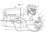
- Fig. 1 is a schematic pictorial illustration of an MRI system 22 and a magnetic position tracking system 20 during a minimally invasive cardiac procedure, in accordance with an embodiment of the present invention.
- MRI system 22 is connected to magnetic position tracking system 20 via an interface 56.
- Magnetic position tracking system 20 comprises a console 26, and a catheter 24, which comprises a distal end 34 as shown in an insert 32 of Fig. 1 .
- a cardiologist 42 navigates catheter 24 in a patient's heart 28, until distal end 34 reaches the desired location in this organ, and then cardiologist 42 performs the medical treatment using distal end 34.
- the disclosed techniques can be used with procedures that are performed in any other organ, and instead of cardiologist 42, any suitable human user can use the system.
- This method of position tracking is implemented, for example, in the CARTOTM system, produced by Biosense Webster Inc. (Diamond Bar, Calif.) and is described in detail in U.S. Patents 5,391,199 , 6,690,963 , 6,484,118 , 6,239,724 , 6,618,612 and 6,332,089 , in PCT Patent Publication WO 96/05768 , and in U.S. Patent Application Publications 2002/0065455 A1 , 2003/0120150 A1 and 2004/0068178 A1 , whose disclosures are all incorporated herein by reference.
- Console 26 comprises a processor 58, a driver circuit 60, interface 56 to MRI system 22, input devices 46, and a display 40.
- Driver circuit 60 drives magnetic field generators 36, which are placed at known positions below a patient's 30 torso.
- cardiologist 42 selects (using input devices 46 and a suitable Graphical User Interface (GUI) on screen 40) a desired plane, which comprises distal end 34.
- GUI Graphical User Interface
- processor 58 selects the desired plane automatically.
- Processor 58 requests a MRI slice of the selected plane from MRI system 22, via interface 56.
- MRI system 22 acquires the requested slice and sends it, via interface 56, to processor 58.
- Processor 58 creates an overlaid image of a 3D magnetic position tracking map with a MRI slice and displays this image on screen 40.
- system 20 shown in Fig. 1 is an example configuration, which is chosen purely for the sake of conceptual clarity. In alternative embodiments, any other suitable configuration can be used for implementing the system. Certain elements of system 20 can be implemented using hardware, such as using one or more Application-Specific Integrated Circuits (ASICs) or Field-Programmable Gate Arrays (FPGAs) or other device types. Additionally or alternatively, certain elements of system 20 can be implemented using software, or using a combination of hardware and software elements.
- ASICs Application-Specific Integrated Circuits
- FPGAs Field-Programmable Gate Arrays
- Processor 58 typically comprises a general-purpose computer, which is programmed in software to carry out the functions described herein.
- the software may be downloaded to the computer in an electronic form, over a network, for example, or it may, alternatively or additionally, be provided and/or stored on non-transitory tangible media, such as magnetic, optical, or electronic memory.
- processor 58 uses the magnetic position tracking capability of system 20 to produce and display a 3D map of the patient heart, overlaid with an image of distal end 34, so cardiologist 42 knows the exact location and orientation of distal end 34 with respect to heart 28.
- cardiologist 42 may need images of the pertinent organ around distal end 42, in real time.
- acquisition of a full volume 3D MRI image takes a long time as it requires volumetric scanning and intensive calculations.
- Other imaging techniques such as X-RAY fluoroscopy, may acquire an image faster than 3D MRI, but there are cases where MRI is needed for the particular treatment and in order to minimize undesired radiation.
- the embodiments described herein fulfill the need for real-time MRI during minimally-invasive procedures in cardiology, and is also suitable for other minimally-invasive medical procedures.
- cardiologist 42 selects a pertinent plane within patient's heart 28, which includes distal end 34.
- Cardiologist 42 defines the desired plane by using input devices 46 and a suitable GUI on screen 40, and processor 58 converts the selected plane into a request for MRI system 22.
- processor 58 sends a request to MRI system 22, via interface 56, to acquire a MRI slice of the desired plane, which comprises distal end 34.
- MRI system 22 acquires the requested slice and sends it back to processor 58 via interface 56.
- Processor 58 creates an overlaid image of the 3D magnetic position tracking map with the recently-acquired MRI slice and displays it on screen 40.
- the overlaid image provides cardiologist 42 a real-time, up-to-date, high-resolution view of the tissue in the vicinity of distal end 34, for the navigation and therapeutic ablation procedures.
- processor 58 selects the desired plane automatically, e.g., in response to a specific event, or periodically.
- Fig. 2 is a schematic pictorial illustration of a MRI slice overlaid on a 3D magnetic position tracking map, in accordance with an embodiment of the present invention.
- MRI system 22 and magnetic position tracking systems 20 generate a MRI slice 44 and a position tracking map 33, respectively.
- cardiologist 42 selects a plane of interest comprising distal end 34 in patient's heart 28, and processor 58 commands MRI system 22, via interface 56, to acquire a MRI slice 44.
- MRI system 22 creates MRI slice 44 and sends it to processor 58 via interface 56.
- Processor 58 displays the overlaid image of slice 44 on 3D position tracking map 33 on screen 40.
- the overlaid image provides cardiologist 42 a real-time high-resolution input for the navigation and treatment procedures.
- processor 58 selects the desired plane automatically.
- Fig. 3 is a flow chart that schematically illustrates a method for acquiring a real-time MRI image and overlaying it with a magnetic position tracking map during an intra-cardiac procedure, in accordance with an embodiment of the present invention.
- the method is divided into a preparation stage and a real-time procedure stage.
- the method can comprise the real-time procedure stage without the preparation stage as, once the MRI scanner and CARTO system are installed and co-registered, the inserted catheter is inherently already registered with the MRI frame of reference.
- the method begins at a 3D MRI acquisition step 200, when the MRI system acquires a 3D image in patient's heart 28.
- a catheter insertion step 210 cardiologist 42 inserts catheter 24 to the patient's heart and magnetic position tracking system 20 creates a magnetic position tracking map in the area of the distal end location.
- the system performs registration to create an overlaid image between the 3D MRI image, which was acquired at 3D MRI acquisition step 200, and the 3D magnetic position tracking map, which was acquired at catheter insertion step 210. This overlaid image helps cardiologist 42 to plan the medical procedure and to navigate distal end 34 to the target locations in patient's heart 28.
- cardiologist 42 navigates catheter 24 to the target location in the patient's heart using the 3D position tracking map and the 3D MRI image. During the navigation, cardiologist 42 may need an updated local MRI image near the distal end of catheter 24.
- cardiologist 42 decides to acquire an MRI image for improved navigation or treatment reasons.
- the need for additional real-time images may be a result of unexpected events during the procedure, such as obstacles encountered during catheter 24 navigation, or to verify that a specific treatment is performed in the target location. Further alternatively, any other suitable event may warrant an acquisition of a MRI slice.
- a slice is not needed, the method loops back to navigation step 230 above, in which cardiologist 42 continues to navigate catheter 24. If decision step 240 concludes that a MRI slice is needed, then the method proceeds to a plane definition step 250.
- plane definition step 250 cardiologist 42 examines the pertinent organ on display 40, and uses input devices 46 and a suitable GUI on display 40 to select the desired plane, which comprises catheter's distal end 34.
- processor 58 sends a request to MRI system 22, via interface 56, to acquire a MRI slice of the plane selected at plane definition step 250 above.
- the request specifies the pertinent plane to MRI system 22, using any suitable convention (e.g. plane equations in some common coordinate system).
- processor 58 also indicates the position coordinates of distal end 34 to MRI system 22.
- MRI system 22 acquires the requested MRI slice and sends it to processor 58 via interface 56.
- Processor 58 receives MRI slice 44 and performs registration between MRI slice 44 and 3D magnetic position tracking map 33. At a display step 270, processor 58 displays the overlaid image between MRI slice 44 and 3D magnetic position tracking map 33 on display 40.
- cardiologist 42 continues navigation or treatment, as described in navigation step 230 and can request additional real-time MRI images for the same plane, as described in plane definition step 250, or for other planes in the vicinity of distal end 34.
- Fig. 3 shows a specific flow of operations; however the techniques described herein are not limited to this specific flow.
- the flow may exclude the preparation stage (steps 200, 210, and 220) and start, for example, directly with the real-time stage (at step 230).
- the plane selection can be done automatically by the system, in specific events or on a periodic basis.
- the methods and systems described herein can also be used in other applications.
- the methods and/or systems can be used for guided needle biopsies, deployment of hepato-billiary stents, exclusion of Abdominal Aortic Aneurysm via stent, and modulation of the Autonomic Nervous System via ablation.
Abstract
Description
- The present invention relates generally to medical imaging, and particularly to methods and systems for real-time MRI in interventional cardiology.
- Magnetic Resonance Imaging (MRI) is commonly used for medical imaging in a variety of applications. MRI processing is typically computationally intensive, and therefore real-time MRI for a large volume is usually feasible at relatively low spatial and temporal resolution.
-
U.S. Patent application publication 2010/0312094, to Guttman, et al. , whose disclosure is incorporated herein by reference, describes MRI-guided surgical systems with preset scan planes. During ablation MR thermometry (2-D) can be used to show real-time ablation formation taking a slice along the catheter and showing the temperature profile increasing. It is contemplated that 2D and/or 3D GRE pulse sequences can be used to obtain the MR image data. However, other pulse sequences may also be used. -
U.S. Patent 8,620,404, to Mistretta , whose disclosure is incorporated herein by reference, describes system and method for generating time-resolved 3D medical images of a subject. The method includes acquiring a time series of two-dimensional (2D) data sets from a portion of the subject using a magnetic resonance imaging (MRI) system and reconstructing the time series of 2D data sets into a 2D time series of images of the subject having a given frame rate. -
U.S. Patent application publication 2013/0184569, to Strommer, et al. , whose disclosure is incorporated herein by reference, describes methods for producing an electrophysiological map of the heart. An example method may include determining a target location and an orientation of a catheter tip, confirming that the tip is located at the target location, measuring the heart parameter value at each of the target locations, and superimposing a plurality of representations of the heart parameter value. -
U.S. Patent 8,675,996, to Liao, et al. , whose disclosure is incorporated herein by reference, describes a method for registering a two-dimensional image of a cardiocirculatory structure and a three-dimensional image of the cardiocirculatory structure. The method includes acquiring a three-dimensional image including the cardiocirculatory structure using a first imaging modality. The acquired three-dimensional image is projected into two-dimensions to produce a two-dimensional projection image of the cardiocirculatory structure. A structure of interest is segmented either from the three-dimensional image prior to projection or from the projection image subsequent to projection. A two-dimensional image of the cardiocirculatory structure is acquired using a second imaging modality. -
U.S. Patent 8,676,300, to Strommer, et al. , whose disclosure is incorporated herein by reference, describes method and system for navigating through an occluded tubular organ. The procedures included injecting a first dye injection into the tubular organ, the first dye approaching a first end of the occluded segment. Multiple first-injection two-dimensional (2D) images of the tubular organ are acquired, each acquired from a different perspective, the first-injection 2D images further acquired with a respective organ timing signal reading. - An embodiment of the present invention that is described herein provides a medical system including an interface and a processor. The interface is configured to communicate with a Magnetic Resonance Imaging (MRI) system. The processor is configured to display a position of a distal end of a medical probe that is being navigated in an organ of a patient on a three-dimensional (3D) map of the organ, and, in response to an event, to select a plane of interest including the distal end, to acquire from the MRI system, via the interface, a real-time MRI slice of the organ at the selected plane, and to display the MRI slice overlaid on the 3D map.
- In some embodiments, the 3D map of the organ is created by a 3D magnetic position tracking system. In other embodiments, the processor is configured to receive a selection of the plane from a user. In alternative embodiments, the processor is configured to choose the plane automatically in response to the event. In yet another embodiment, the organ includes a heart, and the medical probe includes a cardiac catheter.
- There is additionally provided, in accordance with an embodiment of the present invention, a method including displaying a position of a distal end of a medical probe that is being navigated in an organ of a patient on a 3D map of the organ. In response to an event, a plane of interest including the distal end is selected, a real-time MRI slice of the organ is acquired at the selected plane, and the MRI slice is displayed overlaid on the 3D map.
- The present invention will be more fully understood from the following detailed description of the embodiments thereof, taken together with the drawings in which:
-
-
Fig. 1 is a schematic pictorial illustration of an MRI system and a magnetic position tracking system during a minimally invasive cardiac procedure, in accordance with an embodiment of the present invention; -
Fig. 2 is a schematic pictorial illustration of a MRI slice overlaid on a three-dimensional (3D) magnetic position tracking map, in accordance with an embodiment of the present invention; and -
Fig. 3 is a flow chart which schematically illustrates a method for acquiring a real-time MRI image and overlaying it with a magnetic position tracking map during an intra-cardiac procedure, in accordance with an embodiment of the present invention. - Some minimally invasive procedures use magnetic position tracking maps, such as provided by the Biosense Webster CARTO™ system, to navigate a catheter or other medical probe in a patient's body. In some events, a physician needs a real-time image of an organ near a catheter's distal end. MRI is one of the imaging solutions, but 3D MRI requires intensive calculations and therefore usually cannot provide the required resolution in real-time.
- Embodiments of the present invention that are described herein below provide a method and system to obtain real-time imaging of the vicinity of the catheter's distal end during navigation, using a 3D magnetic position tracking map. Instead of acquiring a complete 3D MRI model, which is not feasible to perform in real time, the disclosed techniques acquire and display a MRI slice in a selected plane of interest which contains the catheter's distal end. By settling for an image at a specific plane, the physician can be provided with an overlaid image of an MRI slice on the magnetic position map in real-time.
- In the context of the present patent application and in the claims, the terms "MRI slice" and "2D MRI slice" refer to a thin MRI slice (e.g., 3 millimeters in thickness) acquired by an MRI system on a specified 2D plane. For all practical purposes such a slice is regarded as two-dimensional, even though it has a finite thickness.
- The embodiments described herein refer mainly to cardiac catheters and cardiac procedures. Alternative embodiments, however, are applicable for any minimally-invasive medical procedures such as laparoscopy or endoscopy, and are not limited to cardiac applications.
-
Fig. 1 is a schematic pictorial illustration of anMRI system 22 and a magneticposition tracking system 20 during a minimally invasive cardiac procedure, in accordance with an embodiment of the present invention.MRI system 22 is connected to magneticposition tracking system 20 via aninterface 56. Magneticposition tracking system 20 comprises aconsole 26, and acatheter 24, which comprises adistal end 34 as shown in aninsert 32 ofFig. 1 . - A
cardiologist 42 navigatescatheter 24 in a patient'sheart 28, untildistal end 34 reaches the desired location in this organ, and thencardiologist 42 performs the medical treatment usingdistal end 34. In other embodiments, the disclosed techniques can be used with procedures that are performed in any other organ, and instead ofcardiologist 42, any suitable human user can use the system. - This method of position tracking is implemented, for example, in the CARTO™ system, produced by Biosense Webster Inc. (Diamond Bar, Calif.) and is described in detail in
U.S. Patents 5,391,199 ,6,690,963 ,6,484,118 ,6,239,724 ,6,618,612 and6,332,089 , inPCT Patent Publication WO 96/05768 U.S. Patent Application Publications 2002/0065455 A1 ,2003/0120150 A1 and2004/0068178 A1 , whose disclosures are all incorporated herein by reference. -
Console 26 comprises aprocessor 58, adriver circuit 60,interface 56 toMRI system 22,input devices 46, and adisplay 40.Driver circuit 60 drivesmagnetic field generators 36, which are placed at known positions below a patient's 30 torso. In response to an event,cardiologist 42 selects (usinginput devices 46 and a suitable Graphical User Interface (GUI) on screen 40) a desired plane, which comprisesdistal end 34. In another embodiment,processor 58 selects the desired plane automatically.Processor 58 requests a MRI slice of the selected plane fromMRI system 22, viainterface 56.MRI system 22 acquires the requested slice and sends it, viainterface 56, toprocessor 58. -
Processor 58 creates an overlaid image of a 3D magnetic position tracking map with a MRI slice and displays this image onscreen 40. - The configuration of
system 20 shown inFig. 1 is an example configuration, which is chosen purely for the sake of conceptual clarity. In alternative embodiments, any other suitable configuration can be used for implementing the system. Certain elements ofsystem 20 can be implemented using hardware, such as using one or more Application-Specific Integrated Circuits (ASICs) or Field-Programmable Gate Arrays (FPGAs) or other device types. Additionally or alternatively, certain elements ofsystem 20 can be implemented using software, or using a combination of hardware and software elements. -
Processor 58 typically comprises a general-purpose computer, which is programmed in software to carry out the functions described herein. The software may be downloaded to the computer in an electronic form, over a network, for example, or it may, alternatively or additionally, be provided and/or stored on non-transitory tangible media, such as magnetic, optical, or electronic memory. - Minimally-invasive procedures require external imaging since the physician cannot see the probe during its navigation and treatment. In embodiments of the
present invention processor 58 uses the magnetic position tracking capability ofsystem 20 to produce and display a 3D map of the patient heart, overlaid with an image ofdistal end 34, socardiologist 42 knows the exact location and orientation ofdistal end 34 with respect toheart 28. - During the navigation and treatment process,
cardiologist 42 may need images of the pertinent organ arounddistal end 42, in real time. In case of MRI, acquisition of afull volume 3D MRI image takes a long time as it requires volumetric scanning and intensive calculations. Other imaging techniques, such as X-RAY fluoroscopy, may acquire an image faster than 3D MRI, but there are cases where MRI is needed for the particular treatment and in order to minimize undesired radiation. The embodiments described herein fulfill the need for real-time MRI during minimally-invasive procedures in cardiology, and is also suitable for other minimally-invasive medical procedures. - In case an MRI image is needed in the vicinity of the catheter's distal end,
cardiologist 42 selects a pertinent plane within patient'sheart 28, which includesdistal end 34.Cardiologist 42 defines the desired plane by usinginput devices 46 and a suitable GUI onscreen 40, andprocessor 58 converts the selected plane into a request forMRI system 22. In response to such an event,processor 58 sends a request toMRI system 22, viainterface 56, to acquire a MRI slice of the desired plane, which comprisesdistal end 34. - Since a MRI slice covers a relatively small area and does not require intensive calculations, it can be acquired in real-time.
MRI system 22 acquires the requested slice and sends it back toprocessor 58 viainterface 56.Processor 58 creates an overlaid image of the 3D magnetic position tracking map with the recently-acquired MRI slice and displays it onscreen 40. The overlaid image provides cardiologist 42 a real-time, up-to-date, high-resolution view of the tissue in the vicinity ofdistal end 34, for the navigation and therapeutic ablation procedures. In analternative embodiment processor 58 selects the desired plane automatically, e.g., in response to a specific event, or periodically. -
Fig. 2 is a schematic pictorial illustration of a MRI slice overlaid on a 3D magnetic position tracking map, in accordance with an embodiment of the present invention.MRI system 22 and magneticposition tracking systems 20 generate aMRI slice 44 and aposition tracking map 33, respectively. To produce this overlaid image, as described above,cardiologist 42 selects a plane of interest comprisingdistal end 34 in patient'sheart 28, andprocessor 58commands MRI system 22, viainterface 56, to acquire aMRI slice 44.MRI system 22 createsMRI slice 44 and sends it toprocessor 58 viainterface 56.Processor 58 displays the overlaid image ofslice 44 on 3Dposition tracking map 33 onscreen 40. - The overlaid image provides cardiologist 42 a real-time high-resolution input for the navigation and treatment procedures. In an
alternative embodiment processor 58 selects the desired plane automatically. -
Fig. 3 is a flow chart that schematically illustrates a method for acquiring a real-time MRI image and overlaying it with a magnetic position tracking map during an intra-cardiac procedure, in accordance with an embodiment of the present invention. In this example, the method is divided into a preparation stage and a real-time procedure stage. In other embodiments, however, the method can comprise the real-time procedure stage without the preparation stage as, once the MRI scanner and CARTO system are installed and co-registered, the inserted catheter is inherently already registered with the MRI frame of reference. - The method begins at a 3D
MRI acquisition step 200, when the MRI system acquires a 3D image in patient'sheart 28. At acatheter insertion step 210,cardiologist 42inserts catheter 24 to the patient's heart and magneticposition tracking system 20 creates a magnetic position tracking map in the area of the distal end location. At aregistration step 220, the system performs registration to create an overlaid image between the 3D MRI image, which was acquired at 3DMRI acquisition step 200, and the 3D magnetic position tracking map, which was acquired atcatheter insertion step 210. This overlaid image helpscardiologist 42 to plan the medical procedure and to navigatedistal end 34 to the target locations in patient'sheart 28. - At a
navigation step 230,cardiologist 42 navigatescatheter 24 to the target location in the patient's heart using the 3D position tracking map and the 3D MRI image. During the navigation,cardiologist 42 may need an updated local MRI image near the distal end ofcatheter 24. At adecision step 240,cardiologist 42 decides to acquire an MRI image for improved navigation or treatment reasons. - The need for additional real-time images may be a result of unexpected events during the procedure, such as obstacles encountered during
catheter 24 navigation, or to verify that a specific treatment is performed in the target location. Further alternatively, any other suitable event may warrant an acquisition of a MRI slice. - If a slice is not needed, the method loops back to
navigation step 230 above, in whichcardiologist 42 continues to navigatecatheter 24. Ifdecision step 240 concludes that a MRI slice is needed, then the method proceeds to aplane definition step 250. Atplane definition step 250,cardiologist 42 examines the pertinent organ ondisplay 40, and usesinput devices 46 and a suitable GUI ondisplay 40 to select the desired plane, which comprises catheter'sdistal end 34. - At a
slice acquisition step 260,processor 58 sends a request toMRI system 22, viainterface 56, to acquire a MRI slice of the plane selected atplane definition step 250 above. The request specifies the pertinent plane toMRI system 22, using any suitable convention (e.g. plane equations in some common coordinate system). In someembodiments processor 58 also indicates the position coordinates ofdistal end 34 toMRI system 22. In response to the request,MRI system 22 acquires the requested MRI slice and sends it toprocessor 58 viainterface 56. -
Processor 58 receivesMRI slice 44 and performs registration betweenMRI slice position tracking map 33. At adisplay step 270,processor 58 displays the overlaid image betweenMRI slice position tracking map 33 ondisplay 40. - If applicable,
cardiologist 42 continues navigation or treatment, as described innavigation step 230 and can request additional real-time MRI images for the same plane, as described inplane definition step 250, or for other planes in the vicinity ofdistal end 34. -
Fig. 3 shows a specific flow of operations; however the techniques described herein are not limited to this specific flow. In other embodiments the flow may exclude the preparation stage (steps - The disclosed techniques can be used in various applications, such as the following six examples:
- (1) Acquiring a thin slice of the inter-atrial septum (fossa ovalis) for safely performing a transseptal procedure (crossing the inter-atrial septum from the right atrium to the left atrium).
- (2) Acquiring a thin slice of the Pulmonary Vein os for preplanning and execution of a Pulmonary Vein Isolation procedure.
- (3) Acquiring a thin slice of an Atrio-Ventricular (Tricuspid or Mitral Valves) or Ventriculo-Atrial Valve (Pulmonary or Aortic Valve) for safe crossing, planning and performing of catheter-based repair or replacement of a cardiac valve.
- (4) Acquiring a thin slice of the posterior Left Atrium for depiction of the Esophagus, its course and distance from a planned ablation point or line. Re-acquiring the same slice after completing the ablation procedure to rule out immediate post ablation Esophageal damages (edema, ulceration, perforation).
- (5) Acquiring a thin slice to depict the Right Phrenic Nerve and distance of the nerve from a planned ablation point or line.
- (6) Acquiring a sequence of thin slices to monitor and assess lesion formation all through an ablation.
- Although the embodiments described herein mainly address cardiology, the methods and systems described herein can also be used in other minimally invasive applications, such as endoscopy and laparoscopy.
- Although the embodiments described herein mainly address therapeutic cardiac ablation procedures like treatment of Atrial-Fibrillation, the methods and systems described herein can also be used in other applications. For example, the methods and/or systems can be used for guided needle biopsies, deployment of hepato-billiary stents, exclusion of Abdominal Aortic Aneurysm via stent, and modulation of the Autonomic Nervous System via ablation.
- It will thus be appreciated that the embodiments described above are cited by way of example, and that the present invention is not limited to what has been particularly shown and described hereinabove. Rather, the scope of the present invention includes both combinations and sub-combinations of the various features described hereinabove, as well as variations and modifications thereof which would occur to persons skilled in the art upon reading the foregoing description and which are not disclosed in the prior art. Documents incorporated by reference in the present patent application are to be considered an integral part of the application except that to the extent any terms are defined in these incorporated documents in a manner that conflicts with the definitions made explicitly or implicitly in the present specification, only the definitions in the present specification should be considered.
Claims (10)
- A method, comprising;
displaying a position of a distal end of a medical probe that is being navigated in an organ of a patient on a three-dimensional (3D) map of the organ; and
in response to an event, selecting a plane of interest comprising the distal end, acquiring a real-time Magnetic Resonance Imaging (MRI) slice of the organ at the selected plane, and displaying the MRI slice overlaid on the 3D map. - The method according to claim 1, wherein the 3D map of the organ is created by a 3D magnetic position tracking system.
- The method according to claim 1, wherein selecting the plane of interest comprises receiving a selection of the plane from a user.
- The method according to claim 1, wherein selecting the plane of interest comprises choosing the plane automatically in response to the event.
- The method according to claim 1, wherein the organ comprises a heart, and wherein the medical probe comprises a cardiac catheter.
- A system, comprising;
an interface, which is configured to communicate with a Magnetic Resonance Imaging (MRI) system; and
a processor, which is configured to display a position of a distal end of a medical probe that is being navigated in an organ of a patient on a three-dimensional (3D) map of the organ, and, in response to an event, to select a plane of interest comprising the distal end, to acquire from the MRI system, via the interface, a real-time MRI slice of the organ at the selected plane, and to display the MRI slice overlaid on the 3D map. - The system according to claim 6, wherein the 3D map of the organ is created by a 3D magnetic position tracking system.
- The system according to claim 6, wherein the processor is configured to receive a selection of the plane from a user.
- The system according to claim 6, wherein the processor is configured to choose the plane automatically in response to the event.
- The system according to claim 6, wherein the organ comprises a heart, and wherein the medical probe comprises a cardiac catheter.
Applications Claiming Priority (1)
| Application Number | Priority Date | Filing Date | Title |
|---|---|---|---|
| US14/314,128 US9848799B2 (en) | 2014-06-25 | 2014-06-25 | Real-time generation of MRI slices |
Publications (2)
| Publication Number | Publication Date |
|---|---|
| EP2959832A1 true EP2959832A1 (en) | 2015-12-30 |
| EP2959832B1 EP2959832B1 (en) | 2023-05-24 |
Family
ID=53488233
Family Applications (1)
| Application Number | Title | Priority Date | Filing Date |
|---|---|---|---|
| EP15173555.2A Active EP2959832B1 (en) | 2014-06-25 | 2015-06-24 | Real-time generation of mri slices |
Country Status (7)
| Country | Link |
|---|---|
| US (1) | US9848799B2 (en) |
| EP (1) | EP2959832B1 (en) |
| JP (1) | JP6710501B2 (en) |
| CN (1) | CN105212934B (en) |
| AU (1) | AU2015203332B2 (en) |
| CA (1) | CA2894622A1 (en) |
| IL (1) | IL238901B (en) |
Cited By (1)
| Publication number | Priority date | Publication date | Assignee | Title |
|---|---|---|---|---|
| WO2017142850A1 (en) * | 2016-02-16 | 2017-08-24 | St. Jude Medical, Cardiology Division, Inc. | Methods and systems for electrophysiology mapping using medical images |
Families Citing this family (5)
| Publication number | Priority date | Publication date | Assignee | Title |
|---|---|---|---|---|
| JP6392192B2 (en) * | 2015-09-29 | 2018-09-19 | 富士フイルム株式会社 | Image registration device, method of operating image registration device, and program |
| US11419660B2 (en) * | 2016-02-09 | 2022-08-23 | Andrea Borsic | System and methods for ablation treatment of tissue |
| DE102016214061A1 (en) * | 2016-07-29 | 2018-02-01 | Siemens Healthcare Gmbh | Method for determining two-dimensional image data of at least one sectional area of a detection volume in the context of magnetic resonance imaging |
| EP3675763B1 (en) * | 2017-08-28 | 2023-07-26 | Koninklijke Philips N.V. | Automatic field of view updating of position tracked interventional device |
| CN109620407B (en) * | 2017-10-06 | 2024-02-06 | 皇家飞利浦有限公司 | Treatment trajectory guidance system |
Citations (18)
| Publication number | Priority date | Publication date | Assignee | Title |
|---|---|---|---|---|
| US5391199A (en) | 1993-07-20 | 1995-02-21 | Biosense, Inc. | Apparatus and method for treating cardiac arrhythmias |
| WO1996005768A1 (en) | 1994-08-19 | 1996-02-29 | Biosense, Inc. | Medical diagnosis, treatment and imaging systems |
| US6239724B1 (en) | 1997-12-30 | 2001-05-29 | Remon Medical Technologies, Ltd. | System and method for telemetrically providing intrabody spatial position |
| US6332089B1 (en) | 1996-02-15 | 2001-12-18 | Biosense, Inc. | Medical procedures and apparatus using intrabody probes |
| US20020065455A1 (en) | 1995-01-24 | 2002-05-30 | Shlomo Ben-Haim | Medical diagnosis, treatment and imaging systems |
| US6484118B1 (en) | 2000-07-20 | 2002-11-19 | Biosense, Inc. | Electromagnetic position single axis system |
| US20030120150A1 (en) | 2001-12-21 | 2003-06-26 | Assaf Govari | Wireless position sensor |
| US6618612B1 (en) | 1996-02-15 | 2003-09-09 | Biosense, Inc. | Independently positionable transducers for location system |
| US20040068178A1 (en) | 2002-09-17 | 2004-04-08 | Assaf Govari | High-gradient recursive locating system |
| EP1421913A1 (en) * | 2002-11-19 | 2004-05-26 | Surgical Navigation Technologies, Inc. | Image guided catheter navigation system for cardiac surgery |
| US20100312094A1 (en) | 2009-06-08 | 2010-12-09 | Michael Guttman | Mri-guided surgical systems with preset scan planes |
| US20100317961A1 (en) * | 2009-06-16 | 2010-12-16 | Jenkins Kimble L | MRI-Guided Devices and MRI-Guided Interventional Systems that can Track and Generate Dynamic Visualizations of the Devices in near Real Time |
| EP2481350A1 (en) * | 2011-01-24 | 2012-08-01 | Imris Inc. | Mr compatible stereoscopic viewing device for use in the bore of an mr magnet |
| US20130184569A1 (en) | 2007-05-08 | 2013-07-18 | Gera Strommer | Method for producing an electrophysiological map of the heart |
| US8620404B2 (en) | 2011-07-26 | 2013-12-31 | Wisconsin Alumni Research Foundation | System and method of high-frame rate, time-resolved, three-dimensional magnetic resonance angiograpy |
| WO2014001974A2 (en) * | 2012-06-28 | 2014-01-03 | Koninklijke Philips N.V. | Dedicated user interface for mr-guided interstitial interventions |
| US8675996B2 (en) | 2009-07-29 | 2014-03-18 | Siemens Aktiengesellschaft | Catheter RF ablation using segmentation-based 2D-3D registration |
| US8676300B2 (en) | 2006-09-18 | 2014-03-18 | Mediguide Ltd. | Method and system for navigating through an occluded tubular organ |
Family Cites Families (19)
| Publication number | Priority date | Publication date | Assignee | Title |
|---|---|---|---|---|
| MX9205298A (en) | 1991-09-17 | 1993-05-01 | Steven Carl Quay | GASEOUS ULTRASOUND CONTRASTING MEDIA AND METHOD FOR SELECTING GASES TO BE USED AS ULTRASOUND CONTRASTING MEDIA |
| JP3514547B2 (en) * | 1995-05-25 | 2004-03-31 | 株式会社日立メディコ | Magnetic resonance imaging system |
| US6233476B1 (en) * | 1999-05-18 | 2001-05-15 | Mediguide Ltd. | Medical positioning system |
| US6898302B1 (en) | 1999-05-21 | 2005-05-24 | Emory University | Systems, methods and computer program products for the display and visually driven definition of tomographic image planes in three-dimensional space |
| CA2398967A1 (en) | 2000-02-01 | 2001-08-09 | Albert C. Lardo | Magnetic resonance imaging transseptal needle antenna |
| JP4939700B2 (en) * | 2000-06-05 | 2012-05-30 | 株式会社東芝 | Magnetic resonance imaging system for interventional MRI |
| US6704593B2 (en) | 2001-04-19 | 2004-03-09 | Sunnybrook & Women's College Health Centre | Realtime MR scan prescription using physiological information |
| US6675034B2 (en) | 2001-04-19 | 2004-01-06 | Sunnybrook And Women's Health Sciences Centre | Magnetic resonance imaging using direct, continuous real-time imaging for motion compensation |
| US6968225B2 (en) | 2001-08-24 | 2005-11-22 | General Electric Company | Real-time localization, monitoring, triggering and acquisition of 3D MRI |
| US7945304B2 (en) | 2001-11-20 | 2011-05-17 | Feinberg David A | Ultrasound within MRI scanners for guidance of MRI pulse sequences |
| US7383074B2 (en) | 2004-11-02 | 2008-06-03 | General Electric Company | System and method for real-time localization for gated MR imaging |
| EP2712553A3 (en) * | 2005-01-11 | 2014-09-17 | Volcano Corporation | Vascular image co-registration |
| US8303505B2 (en) * | 2005-12-02 | 2012-11-06 | Abbott Cardiovascular Systems Inc. | Methods and apparatuses for image guided medical procedures |
| US9002433B2 (en) * | 2006-04-20 | 2015-04-07 | General Electric Company | System and method for image-based interventional device tracking and scan plane guidance |
| US8805034B2 (en) * | 2006-08-11 | 2014-08-12 | Koninklijke Philips N.V. | Selection of datasets from 3D renderings for viewing |
| IL188569A (en) | 2007-01-17 | 2014-05-28 | Mediguide Ltd | Method and system for registering a 3d pre-acquired image coordinate system with a medical positioning system coordinate system and with a 2d image coordinate system |
| US8583209B2 (en) | 2007-10-03 | 2013-11-12 | Siemens Aktiengesellschaft | Method and system for monitoring cardiac function of a patient during a magnetic resonance imaging (MRI) procedure |
| US9066673B2 (en) * | 2010-09-01 | 2015-06-30 | Mark A. Griswold | Wireless/intervention-independent scan plane control for an MRI to track a catheter in a body |
| EP2699926B1 (en) | 2011-04-21 | 2015-07-29 | Max-Planck-Gesellschaft zur Förderung der Wissenschaften e.V. | Spatially encoded phase-contrast mri |
-
2014
- 2014-06-25 US US14/314,128 patent/US9848799B2/en active Active
-
2015
- 2015-05-19 IL IL238901A patent/IL238901B/en active IP Right Grant
- 2015-06-17 AU AU2015203332A patent/AU2015203332B2/en not_active Ceased
- 2015-06-17 CA CA2894622A patent/CA2894622A1/en active Pending
- 2015-06-24 JP JP2015126298A patent/JP6710501B2/en active Active
- 2015-06-24 EP EP15173555.2A patent/EP2959832B1/en active Active
- 2015-06-25 CN CN201510359175.6A patent/CN105212934B/en active Active
Patent Citations (19)
| Publication number | Priority date | Publication date | Assignee | Title |
|---|---|---|---|---|
| US5391199A (en) | 1993-07-20 | 1995-02-21 | Biosense, Inc. | Apparatus and method for treating cardiac arrhythmias |
| WO1996005768A1 (en) | 1994-08-19 | 1996-02-29 | Biosense, Inc. | Medical diagnosis, treatment and imaging systems |
| US6690963B2 (en) | 1995-01-24 | 2004-02-10 | Biosense, Inc. | System for determining the location and orientation of an invasive medical instrument |
| US20020065455A1 (en) | 1995-01-24 | 2002-05-30 | Shlomo Ben-Haim | Medical diagnosis, treatment and imaging systems |
| US6618612B1 (en) | 1996-02-15 | 2003-09-09 | Biosense, Inc. | Independently positionable transducers for location system |
| US6332089B1 (en) | 1996-02-15 | 2001-12-18 | Biosense, Inc. | Medical procedures and apparatus using intrabody probes |
| US6239724B1 (en) | 1997-12-30 | 2001-05-29 | Remon Medical Technologies, Ltd. | System and method for telemetrically providing intrabody spatial position |
| US6484118B1 (en) | 2000-07-20 | 2002-11-19 | Biosense, Inc. | Electromagnetic position single axis system |
| US20030120150A1 (en) | 2001-12-21 | 2003-06-26 | Assaf Govari | Wireless position sensor |
| US20040068178A1 (en) | 2002-09-17 | 2004-04-08 | Assaf Govari | High-gradient recursive locating system |
| EP1421913A1 (en) * | 2002-11-19 | 2004-05-26 | Surgical Navigation Technologies, Inc. | Image guided catheter navigation system for cardiac surgery |
| US8676300B2 (en) | 2006-09-18 | 2014-03-18 | Mediguide Ltd. | Method and system for navigating through an occluded tubular organ |
| US20130184569A1 (en) | 2007-05-08 | 2013-07-18 | Gera Strommer | Method for producing an electrophysiological map of the heart |
| US20100312094A1 (en) | 2009-06-08 | 2010-12-09 | Michael Guttman | Mri-guided surgical systems with preset scan planes |
| US20100317961A1 (en) * | 2009-06-16 | 2010-12-16 | Jenkins Kimble L | MRI-Guided Devices and MRI-Guided Interventional Systems that can Track and Generate Dynamic Visualizations of the Devices in near Real Time |
| US8675996B2 (en) | 2009-07-29 | 2014-03-18 | Siemens Aktiengesellschaft | Catheter RF ablation using segmentation-based 2D-3D registration |
| EP2481350A1 (en) * | 2011-01-24 | 2012-08-01 | Imris Inc. | Mr compatible stereoscopic viewing device for use in the bore of an mr magnet |
| US8620404B2 (en) | 2011-07-26 | 2013-12-31 | Wisconsin Alumni Research Foundation | System and method of high-frame rate, time-resolved, three-dimensional magnetic resonance angiograpy |
| WO2014001974A2 (en) * | 2012-06-28 | 2014-01-03 | Koninklijke Philips N.V. | Dedicated user interface for mr-guided interstitial interventions |
Cited By (1)
| Publication number | Priority date | Publication date | Assignee | Title |
|---|---|---|---|---|
| WO2017142850A1 (en) * | 2016-02-16 | 2017-08-24 | St. Jude Medical, Cardiology Division, Inc. | Methods and systems for electrophysiology mapping using medical images |
Also Published As
| Publication number | Publication date |
|---|---|
| AU2015203332A1 (en) | 2016-01-21 |
| US9848799B2 (en) | 2017-12-26 |
| CN105212934A (en) | 2016-01-06 |
| JP2016007540A (en) | 2016-01-18 |
| JP6710501B2 (en) | 2020-06-17 |
| CA2894622A1 (en) | 2015-12-25 |
| IL238901B (en) | 2019-03-31 |
| AU2015203332B2 (en) | 2019-06-27 |
| US20150374260A1 (en) | 2015-12-31 |
| EP2959832B1 (en) | 2023-05-24 |
| CN105212934B (en) | 2020-12-11 |
Similar Documents
| Publication | Publication Date | Title |
|---|---|---|
| EP2959832B1 (en) | Real-time generation of mri slices | |
| JP5632286B2 (en) | MRI surgical system that visualizes in real time using MRI image data and predefined data of surgical tools | |
| US20190307516A1 (en) | Image-based navigation system and method of using same | |
| EP3236854B1 (en) | Tracking-based 3d model enhancement | |
| EP3363365B1 (en) | Automatic imaging plane selection for echocardiography | |
| AU2015238800B2 (en) | Real-time simulation of fluoroscopic images | |
| JP2014522274A (en) | Method and system for superimposing induced brain stimulation function data on live brain image | |
| US11707255B2 (en) | Image-based probe positioning | |
| Linte et al. | Virtual reality-enhanced ultrasound guidance: A novel technique for intracardiac interventions | |
| EP3558151B1 (en) | Navigation platform for an intracardiac catheter | |
| CN108430376B (en) | Providing a projection data set | |
| JP7319248B2 (en) | Automatic field-of-view update for position-tracking interventional devices | |
| US11596478B2 (en) | Characterizing behavior of anatomical structures | |
| JP2023548773A (en) | Automatic segmentation and registration system and method | |
| Jeevan et al. | In-vitro validation of image guided surgery system with 3d pre-operative visualization for atrial transseptal puncture | |
| JP6068032B2 (en) | Medical image processing device | |
| EP3576661A1 (en) | Characterizing behavior of anatomical structures | |
| BR112014029565B1 (en) | ULTRASOUND IMAGE FORMATION SYSTEM AND ULTRASOUND IMAGE SUPPLY METHOD WITH VESSEL INFORMATION |
Legal Events
| Date | Code | Title | Description |
|---|---|---|---|
| PUAI | Public reference made under article 153(3) epc to a published international application that has entered the european phase |
Free format text: ORIGINAL CODE: 0009012 |
|
| AK | Designated contracting states |
Kind code of ref document: A1 Designated state(s): AL AT BE BG CH CY CZ DE DK EE ES FI FR GB GR HR HU IE IS IT LI LT LU LV MC MK MT NL NO PL PT RO RS SE SI SK SM TR |
|
| AX | Request for extension of the european patent |
Extension state: BA ME |
|
| 17P | Request for examination filed |
Effective date: 20160629 |
|
| RBV | Designated contracting states (corrected) |
Designated state(s): AL AT BE BG CH CY CZ DE DK EE ES FI FR GB GR HR HU IE IS IT LI LT LU LV MC MK MT NL NO PL PT RO RS SE SI SK SM TR |
|
| STAA | Information on the status of an ep patent application or granted ep patent |
Free format text: STATUS: EXAMINATION IS IN PROGRESS |
|
| 17Q | First examination report despatched |
Effective date: 20180919 |
|
| STAA | Information on the status of an ep patent application or granted ep patent |
Free format text: STATUS: EXAMINATION IS IN PROGRESS |
|
| STAA | Information on the status of an ep patent application or granted ep patent |
Free format text: STATUS: EXAMINATION IS IN PROGRESS |
|
| RAP3 | Party data changed (applicant data changed or rights of an application transferred) |
Owner name: BIOSENSE WEBSTER (ISRAEL) LTD. |
|
| GRAP | Despatch of communication of intention to grant a patent |
Free format text: ORIGINAL CODE: EPIDOSNIGR1 |
|
| STAA | Information on the status of an ep patent application or granted ep patent |
Free format text: STATUS: GRANT OF PATENT IS INTENDED |
|
| RIC1 | Information provided on ipc code assigned before grant |
Ipc: G01R 33/28 20060101ALI20221031BHEP Ipc: A61B 5/06 20060101ALI20221031BHEP Ipc: A61B 5/055 20060101AFI20221031BHEP |
|
| INTG | Intention to grant announced |
Effective date: 20221128 |
|
| GRAS | Grant fee paid |
Free format text: ORIGINAL CODE: EPIDOSNIGR3 |
|
| GRAA | (expected) grant |
Free format text: ORIGINAL CODE: 0009210 |
|
| STAA | Information on the status of an ep patent application or granted ep patent |
Free format text: STATUS: THE PATENT HAS BEEN GRANTED |
|
| AK | Designated contracting states |
Kind code of ref document: B1 Designated state(s): AL AT BE BG CH CY CZ DE DK EE ES FI FR GB GR HR HU IE IS IT LI LT LU LV MC MK MT NL NO PL PT RO RS SE SI SK SM TR |
|
| REG | Reference to a national code |
Ref country code: GB Ref legal event code: FG4D |
|
| REG | Reference to a national code |
Ref country code: CH Ref legal event code: EP |
|
| REG | Reference to a national code |
Ref country code: DE Ref legal event code: R096 Ref document number: 602015083652 Country of ref document: DE |
|
| REG | Reference to a national code |
Ref country code: AT Ref legal event code: REF Ref document number: 1569049 Country of ref document: AT Kind code of ref document: T Effective date: 20230615 |
|
| REG | Reference to a national code |
Ref country code: IE Ref legal event code: FG4D |
|
| PGFP | Annual fee paid to national office [announced via postgrant information from national office to epo] |
Ref country code: FR Payment date: 20230620 Year of fee payment: 9 Ref country code: DE Payment date: 20230524 Year of fee payment: 9 |
|
| REG | Reference to a national code |
Ref country code: LT Ref legal event code: MG9D |
|
| REG | Reference to a national code |
Ref country code: NL Ref legal event code: MP Effective date: 20230524 |
|
| REG | Reference to a national code |
Ref country code: AT Ref legal event code: MK05 Ref document number: 1569049 Country of ref document: AT Kind code of ref document: T Effective date: 20230524 |
|
| PG25 | Lapsed in a contracting state [announced via postgrant information from national office to epo] |
Ref country code: SE Free format text: LAPSE BECAUSE OF FAILURE TO SUBMIT A TRANSLATION OF THE DESCRIPTION OR TO PAY THE FEE WITHIN THE PRESCRIBED TIME-LIMIT Effective date: 20230524 Ref country code: PT Free format text: LAPSE BECAUSE OF FAILURE TO SUBMIT A TRANSLATION OF THE DESCRIPTION OR TO PAY THE FEE WITHIN THE PRESCRIBED TIME-LIMIT Effective date: 20230925 Ref country code: NO Free format text: LAPSE BECAUSE OF FAILURE TO SUBMIT A TRANSLATION OF THE DESCRIPTION OR TO PAY THE FEE WITHIN THE PRESCRIBED TIME-LIMIT Effective date: 20230824 Ref country code: NL Free format text: LAPSE BECAUSE OF FAILURE TO SUBMIT A TRANSLATION OF THE DESCRIPTION OR TO PAY THE FEE WITHIN THE PRESCRIBED TIME-LIMIT Effective date: 20230524 Ref country code: ES Free format text: LAPSE BECAUSE OF FAILURE TO SUBMIT A TRANSLATION OF THE DESCRIPTION OR TO PAY THE FEE WITHIN THE PRESCRIBED TIME-LIMIT Effective date: 20230524 Ref country code: AT Free format text: LAPSE BECAUSE OF FAILURE TO SUBMIT A TRANSLATION OF THE DESCRIPTION OR TO PAY THE FEE WITHIN THE PRESCRIBED TIME-LIMIT Effective date: 20230524 |
|
| PGFP | Annual fee paid to national office [announced via postgrant information from national office to epo] |
Ref country code: IT Payment date: 20230626 Year of fee payment: 9 Ref country code: GB Payment date: 20230525 Year of fee payment: 9 |
|
| PG25 | Lapsed in a contracting state [announced via postgrant information from national office to epo] |
Ref country code: RS Free format text: LAPSE BECAUSE OF FAILURE TO SUBMIT A TRANSLATION OF THE DESCRIPTION OR TO PAY THE FEE WITHIN THE PRESCRIBED TIME-LIMIT Effective date: 20230524 Ref country code: PL Free format text: LAPSE BECAUSE OF FAILURE TO SUBMIT A TRANSLATION OF THE DESCRIPTION OR TO PAY THE FEE WITHIN THE PRESCRIBED TIME-LIMIT Effective date: 20230524 Ref country code: LV Free format text: LAPSE BECAUSE OF FAILURE TO SUBMIT A TRANSLATION OF THE DESCRIPTION OR TO PAY THE FEE WITHIN THE PRESCRIBED TIME-LIMIT Effective date: 20230524 Ref country code: LT Free format text: LAPSE BECAUSE OF FAILURE TO SUBMIT A TRANSLATION OF THE DESCRIPTION OR TO PAY THE FEE WITHIN THE PRESCRIBED TIME-LIMIT Effective date: 20230524 Ref country code: IS Free format text: LAPSE BECAUSE OF FAILURE TO SUBMIT A TRANSLATION OF THE DESCRIPTION OR TO PAY THE FEE WITHIN THE PRESCRIBED TIME-LIMIT Effective date: 20230924 Ref country code: HR Free format text: LAPSE BECAUSE OF FAILURE TO SUBMIT A TRANSLATION OF THE DESCRIPTION OR TO PAY THE FEE WITHIN THE PRESCRIBED TIME-LIMIT Effective date: 20230524 Ref country code: GR Free format text: LAPSE BECAUSE OF FAILURE TO SUBMIT A TRANSLATION OF THE DESCRIPTION OR TO PAY THE FEE WITHIN THE PRESCRIBED TIME-LIMIT Effective date: 20230825 |
|
| PG25 | Lapsed in a contracting state [announced via postgrant information from national office to epo] |
Ref country code: FI Free format text: LAPSE BECAUSE OF FAILURE TO SUBMIT A TRANSLATION OF THE DESCRIPTION OR TO PAY THE FEE WITHIN THE PRESCRIBED TIME-LIMIT Effective date: 20230524 |
|
| PG25 | Lapsed in a contracting state [announced via postgrant information from national office to epo] |
Ref country code: SK Free format text: LAPSE BECAUSE OF FAILURE TO SUBMIT A TRANSLATION OF THE DESCRIPTION OR TO PAY THE FEE WITHIN THE PRESCRIBED TIME-LIMIT Effective date: 20230524 |
|
| PG25 | Lapsed in a contracting state [announced via postgrant information from national office to epo] |
Ref country code: SM Free format text: LAPSE BECAUSE OF FAILURE TO SUBMIT A TRANSLATION OF THE DESCRIPTION OR TO PAY THE FEE WITHIN THE PRESCRIBED TIME-LIMIT Effective date: 20230524 Ref country code: SK Free format text: LAPSE BECAUSE OF FAILURE TO SUBMIT A TRANSLATION OF THE DESCRIPTION OR TO PAY THE FEE WITHIN THE PRESCRIBED TIME-LIMIT Effective date: 20230524 Ref country code: RO Free format text: LAPSE BECAUSE OF FAILURE TO SUBMIT A TRANSLATION OF THE DESCRIPTION OR TO PAY THE FEE WITHIN THE PRESCRIBED TIME-LIMIT Effective date: 20230524 Ref country code: EE Free format text: LAPSE BECAUSE OF FAILURE TO SUBMIT A TRANSLATION OF THE DESCRIPTION OR TO PAY THE FEE WITHIN THE PRESCRIBED TIME-LIMIT Effective date: 20230524 Ref country code: DK Free format text: LAPSE BECAUSE OF FAILURE TO SUBMIT A TRANSLATION OF THE DESCRIPTION OR TO PAY THE FEE WITHIN THE PRESCRIBED TIME-LIMIT Effective date: 20230524 Ref country code: CZ Free format text: LAPSE BECAUSE OF FAILURE TO SUBMIT A TRANSLATION OF THE DESCRIPTION OR TO PAY THE FEE WITHIN THE PRESCRIBED TIME-LIMIT Effective date: 20230524 |
|
| REG | Reference to a national code |
Ref country code: CH Ref legal event code: PL |
|
| REG | Reference to a national code |
Ref country code: BE Ref legal event code: MM Effective date: 20230630 |
|
| PG25 | Lapsed in a contracting state [announced via postgrant information from national office to epo] |
Ref country code: MC Free format text: LAPSE BECAUSE OF FAILURE TO SUBMIT A TRANSLATION OF THE DESCRIPTION OR TO PAY THE FEE WITHIN THE PRESCRIBED TIME-LIMIT Effective date: 20230524 |
|
| PG25 | Lapsed in a contracting state [announced via postgrant information from national office to epo] |
Ref country code: MC Free format text: LAPSE BECAUSE OF FAILURE TO SUBMIT A TRANSLATION OF THE DESCRIPTION OR TO PAY THE FEE WITHIN THE PRESCRIBED TIME-LIMIT Effective date: 20230524 |
|
| PG25 | Lapsed in a contracting state [announced via postgrant information from national office to epo] |
Ref country code: LU Free format text: LAPSE BECAUSE OF NON-PAYMENT OF DUE FEES Effective date: 20230624 |
|
| PG25 | Lapsed in a contracting state [announced via postgrant information from national office to epo] |
Ref country code: LU Free format text: LAPSE BECAUSE OF NON-PAYMENT OF DUE FEES Effective date: 20230624 |
|
| PLBE | No opposition filed within time limit |
Free format text: ORIGINAL CODE: 0009261 |
|
| STAA | Information on the status of an ep patent application or granted ep patent |
Free format text: STATUS: NO OPPOSITION FILED WITHIN TIME LIMIT |