EP2960910A1 - Power transmission device and power receiving device - Google Patents
Power transmission device and power receiving device Download PDFInfo
- Publication number
- EP2960910A1 EP2960910A1 EP15166700.3A EP15166700A EP2960910A1 EP 2960910 A1 EP2960910 A1 EP 2960910A1 EP 15166700 A EP15166700 A EP 15166700A EP 2960910 A1 EP2960910 A1 EP 2960910A1
- Authority
- EP
- European Patent Office
- Prior art keywords
- power
- power transmission
- housing
- devices
- unit
- Prior art date
- Legal status (The legal status is an assumption and is not a legal conclusion. Google has not performed a legal analysis and makes no representation as to the accuracy of the status listed.)
- Granted
Links
Images


Classifications
-
- H—ELECTRICITY
- H02—GENERATION; CONVERSION OR DISTRIBUTION OF ELECTRIC POWER
- H02J—CIRCUIT ARRANGEMENTS OR SYSTEMS FOR SUPPLYING OR DISTRIBUTING ELECTRIC POWER; SYSTEMS FOR STORING ELECTRIC ENERGY
- H02J50/00—Circuit arrangements or systems for wireless supply or distribution of electric power
- H02J50/005—Mechanical details of housing or structure aiming to accommodate the power transfer means, e.g. mechanical integration of coils, antennas or transducers into emitting or receiving devices
-
- B—PERFORMING OPERATIONS; TRANSPORTING
- B60—VEHICLES IN GENERAL
- B60L—PROPULSION OF ELECTRICALLY-PROPELLED VEHICLES; SUPPLYING ELECTRIC POWER FOR AUXILIARY EQUIPMENT OF ELECTRICALLY-PROPELLED VEHICLES; ELECTRODYNAMIC BRAKE SYSTEMS FOR VEHICLES IN GENERAL; MAGNETIC SUSPENSION OR LEVITATION FOR VEHICLES; MONITORING OPERATING VARIABLES OF ELECTRICALLY-PROPELLED VEHICLES; ELECTRIC SAFETY DEVICES FOR ELECTRICALLY-PROPELLED VEHICLES
- B60L53/00—Methods of charging batteries, specially adapted for electric vehicles; Charging stations or on-board charging equipment therefor; Exchange of energy storage elements in electric vehicles
- B60L53/10—Methods of charging batteries, specially adapted for electric vehicles; Charging stations or on-board charging equipment therefor; Exchange of energy storage elements in electric vehicles characterised by the energy transfer between the charging station and the vehicle
- B60L53/12—Inductive energy transfer
-
- B—PERFORMING OPERATIONS; TRANSPORTING
- B60—VEHICLES IN GENERAL
- B60L—PROPULSION OF ELECTRICALLY-PROPELLED VEHICLES; SUPPLYING ELECTRIC POWER FOR AUXILIARY EQUIPMENT OF ELECTRICALLY-PROPELLED VEHICLES; ELECTRODYNAMIC BRAKE SYSTEMS FOR VEHICLES IN GENERAL; MAGNETIC SUSPENSION OR LEVITATION FOR VEHICLES; MONITORING OPERATING VARIABLES OF ELECTRICALLY-PROPELLED VEHICLES; ELECTRIC SAFETY DEVICES FOR ELECTRICALLY-PROPELLED VEHICLES
- B60L53/00—Methods of charging batteries, specially adapted for electric vehicles; Charging stations or on-board charging equipment therefor; Exchange of energy storage elements in electric vehicles
- B60L53/30—Constructional details of charging stations
- B60L53/35—Means for automatic or assisted adjustment of the relative position of charging devices and vehicles
- B60L53/36—Means for automatic or assisted adjustment of the relative position of charging devices and vehicles by positioning the vehicle
-
- B—PERFORMING OPERATIONS; TRANSPORTING
- B60—VEHICLES IN GENERAL
- B60L—PROPULSION OF ELECTRICALLY-PROPELLED VEHICLES; SUPPLYING ELECTRIC POWER FOR AUXILIARY EQUIPMENT OF ELECTRICALLY-PROPELLED VEHICLES; ELECTRODYNAMIC BRAKE SYSTEMS FOR VEHICLES IN GENERAL; MAGNETIC SUSPENSION OR LEVITATION FOR VEHICLES; MONITORING OPERATING VARIABLES OF ELECTRICALLY-PROPELLED VEHICLES; ELECTRIC SAFETY DEVICES FOR ELECTRICALLY-PROPELLED VEHICLES
- B60L53/00—Methods of charging batteries, specially adapted for electric vehicles; Charging stations or on-board charging equipment therefor; Exchange of energy storage elements in electric vehicles
- B60L53/30—Constructional details of charging stations
- B60L53/35—Means for automatic or assisted adjustment of the relative position of charging devices and vehicles
- B60L53/38—Means for automatic or assisted adjustment of the relative position of charging devices and vehicles specially adapted for charging by inductive energy transfer
-
- H—ELECTRICITY
- H01—ELECTRIC ELEMENTS
- H01F—MAGNETS; INDUCTANCES; TRANSFORMERS; SELECTION OF MATERIALS FOR THEIR MAGNETIC PROPERTIES
- H01F27/00—Details of transformers or inductances, in general
- H01F27/02—Casings
-
- H—ELECTRICITY
- H01—ELECTRIC ELEMENTS
- H01F—MAGNETS; INDUCTANCES; TRANSFORMERS; SELECTION OF MATERIALS FOR THEIR MAGNETIC PROPERTIES
- H01F27/00—Details of transformers or inductances, in general
- H01F27/40—Structural association with built-in electric component, e.g. fuse
-
- H—ELECTRICITY
- H01—ELECTRIC ELEMENTS
- H01F—MAGNETS; INDUCTANCES; TRANSFORMERS; SELECTION OF MATERIALS FOR THEIR MAGNETIC PROPERTIES
- H01F38/00—Adaptations of transformers or inductances for specific applications or functions
- H01F38/14—Inductive couplings
-
- H—ELECTRICITY
- H02—GENERATION; CONVERSION OR DISTRIBUTION OF ELECTRIC POWER
- H02J—CIRCUIT ARRANGEMENTS OR SYSTEMS FOR SUPPLYING OR DISTRIBUTING ELECTRIC POWER; SYSTEMS FOR STORING ELECTRIC ENERGY
- H02J50/00—Circuit arrangements or systems for wireless supply or distribution of electric power
- H02J50/10—Circuit arrangements or systems for wireless supply or distribution of electric power using inductive coupling
- H02J50/12—Circuit arrangements or systems for wireless supply or distribution of electric power using inductive coupling of the resonant type
-
- H—ELECTRICITY
- H02—GENERATION; CONVERSION OR DISTRIBUTION OF ELECTRIC POWER
- H02J—CIRCUIT ARRANGEMENTS OR SYSTEMS FOR SUPPLYING OR DISTRIBUTING ELECTRIC POWER; SYSTEMS FOR STORING ELECTRIC ENERGY
- H02J7/00—Circuit arrangements for charging or depolarising batteries or for supplying loads from batteries
- H02J7/0042—Circuit arrangements for charging or depolarising batteries or for supplying loads from batteries characterised by the mechanical construction
-
- H—ELECTRICITY
- H01—ELECTRIC ELEMENTS
- H01F—MAGNETS; INDUCTANCES; TRANSFORMERS; SELECTION OF MATERIALS FOR THEIR MAGNETIC PROPERTIES
- H01F27/00—Details of transformers or inductances, in general
- H01F27/02—Casings
- H01F27/025—Constructional details relating to cooling
-
- Y—GENERAL TAGGING OF NEW TECHNOLOGICAL DEVELOPMENTS; GENERAL TAGGING OF CROSS-SECTIONAL TECHNOLOGIES SPANNING OVER SEVERAL SECTIONS OF THE IPC; TECHNICAL SUBJECTS COVERED BY FORMER USPC CROSS-REFERENCE ART COLLECTIONS [XRACs] AND DIGESTS
- Y02—TECHNOLOGIES OR APPLICATIONS FOR MITIGATION OR ADAPTATION AGAINST CLIMATE CHANGE
- Y02T—CLIMATE CHANGE MITIGATION TECHNOLOGIES RELATED TO TRANSPORTATION
- Y02T10/00—Road transport of goods or passengers
- Y02T10/60—Other road transportation technologies with climate change mitigation effect
- Y02T10/70—Energy storage systems for electromobility, e.g. batteries
-
- Y—GENERAL TAGGING OF NEW TECHNOLOGICAL DEVELOPMENTS; GENERAL TAGGING OF CROSS-SECTIONAL TECHNOLOGIES SPANNING OVER SEVERAL SECTIONS OF THE IPC; TECHNICAL SUBJECTS COVERED BY FORMER USPC CROSS-REFERENCE ART COLLECTIONS [XRACs] AND DIGESTS
- Y02—TECHNOLOGIES OR APPLICATIONS FOR MITIGATION OR ADAPTATION AGAINST CLIMATE CHANGE
- Y02T—CLIMATE CHANGE MITIGATION TECHNOLOGIES RELATED TO TRANSPORTATION
- Y02T10/00—Road transport of goods or passengers
- Y02T10/60—Other road transportation technologies with climate change mitigation effect
- Y02T10/7072—Electromobility specific charging systems or methods for batteries, ultracapacitors, supercapacitors or double-layer capacitors
-
- Y—GENERAL TAGGING OF NEW TECHNOLOGICAL DEVELOPMENTS; GENERAL TAGGING OF CROSS-SECTIONAL TECHNOLOGIES SPANNING OVER SEVERAL SECTIONS OF THE IPC; TECHNICAL SUBJECTS COVERED BY FORMER USPC CROSS-REFERENCE ART COLLECTIONS [XRACs] AND DIGESTS
- Y02—TECHNOLOGIES OR APPLICATIONS FOR MITIGATION OR ADAPTATION AGAINST CLIMATE CHANGE
- Y02T—CLIMATE CHANGE MITIGATION TECHNOLOGIES RELATED TO TRANSPORTATION
- Y02T90/00—Enabling technologies or technologies with a potential or indirect contribution to GHG emissions mitigation
- Y02T90/10—Technologies relating to charging of electric vehicles
- Y02T90/12—Electric charging stations
-
- Y—GENERAL TAGGING OF NEW TECHNOLOGICAL DEVELOPMENTS; GENERAL TAGGING OF CROSS-SECTIONAL TECHNOLOGIES SPANNING OVER SEVERAL SECTIONS OF THE IPC; TECHNICAL SUBJECTS COVERED BY FORMER USPC CROSS-REFERENCE ART COLLECTIONS [XRACs] AND DIGESTS
- Y02—TECHNOLOGIES OR APPLICATIONS FOR MITIGATION OR ADAPTATION AGAINST CLIMATE CHANGE
- Y02T—CLIMATE CHANGE MITIGATION TECHNOLOGIES RELATED TO TRANSPORTATION
- Y02T90/00—Enabling technologies or technologies with a potential or indirect contribution to GHG emissions mitigation
- Y02T90/10—Technologies relating to charging of electric vehicles
- Y02T90/14—Plug-in electric vehicles
Definitions
- the present invention relates to a power transmission device for transmitting power to a power receiving device in a noncontact manner, and a power receiving device for receiving power from a power transmission device in a noncontact manner.
- Japanese Patent Laying-Open Nos. 2013-154815 , 2013-146154 , 2013-146148 , 2013-110822 , and 2013-126327 there have been known power transmission systems using power transmission devices and power receiving devices for transmitting and receiving power in a noncontact manner.
- Japanese Patent Laying-Open Nos. 2014-011939 and 2014-011332 each describe a configuration in which a coil unit including ferrite and a coil, and a capacitor connected to the coil are provided, and the capacitor is housed in the same housing where the coil unit is housed.
- a high frequency power source and the like need to be provided in addition to the capacitor and the coil unit. Therefore, a management side of a charging station needs to install not only a power transmission device but also a high frequency power source.
- the capacitor is disposed at a position adjacent to the coil unit.
- peripheral devices such as a high frequency power source are disposed around the coil unit, a size of a housing horizontally increases, and an installation area increases.
- the coil unit in a case where the coil unit largely protrudes downward beyond devices disposed around the coil unit, a problem that when the power receiving device comes into contact with unevenness (e.g., a railroad crossing) of the ground, a falling object on the ground, or other obstacle, the coil unit is damaged is caused.
- unevenness e.g., a railroad crossing
- the present invention has been made in view of the above problems, and an object of the present invention is to provide a power transmission device and a power receiving device, each of which suppresses increase in size in a case where peripheral devices are housed in a single housing to be integrated, and suppresses damage of a coil unit when external power from wheels of a vehicle is applied.
- the power supply unit includes first devices disposed around the power transmission unit, and a second device disposed between the power transmission unit and the bottom surface of the housing, in a state where the power receiving unit and the apparatus unit are mounted on the bottom surface of the housing, and a height of each of the first devices from the bottom surface of the housing is higher than a height of the second device from the bottom surface.
- an upper surface of the power transmission unit is approximate to a height of an upper surface of each of the first devices located around the power transmission unit, so that the upper surface of the power transmission unit can be inhibited from protruding upward. Consequently, even when wheels of a vehicle run on the power transmission device, a large load can be inhibited from being applied to the power transmission unit.
- the second device is disposed on a lower surface of the power transmission unit, the height of each first device disposed around the power transmission unit is made higher, and installation areas of the first devices are reduced, so that an installation area of a whole of the power transmission device can be inhibited from increasing.
- the apparatus unit includes first devices disposed around the power receiving unit, and a second device disposed between the power receiving unit and a bottom surface of the housing, in a state where the power receiving unit and the apparatus unit are mounted on the bottom surface of the housing, and a height of each of the first devices from the bottom surface of the housing is higher than a height of the second device from the bottom surface of the housing.
- the power receiving unit is inhibited from largely protruding downward beyond the first devices located around the power receiving unit. Consequently, even when the power receiving device interferes with the ground, a large load is inhibited from being applied to the power receiving unit.
- the second device is disposed on a lower surface of the power receiving unit, and the height of each first device disposed around the power receiving unit is made higher, and installation areas of the first devices are reduced, so that an installation area of a whole of the power receiving device is inhibited from increasing.
- a bottom surface side means the facility (ground) side
- a front surface side means a power receiving device (vehicle) side
- a bottom surface side means the vehicle side
- a front surface side means a power transmission device (ground) side.
- a direction shown by an arrow F in the drawing indicates an entry direction and an advancing direction (including retreating) of a vehicle
- a direction shown by an arrow W in the drawing indicates a width direction of the vehicle.
- Power transmission system 1000 includes a power receiving device 10 mounted on an electric vehicle 100, and a power transmission device 50 installed on a facility side such as a parking area.
- Electric vehicle 100 includes power receiving device 10 and a vehicle body 105.
- Power receiving device 10 includes a power receiving unit 200, and an apparatus unit 110 provided between power receiving unit 200 and a battery 150 serving a storage device for storing power received by power receiving unit 200.
- Power receiving unit 200 has a power receiving coil 250 and a plate shaped ferrite core 260.
- power receiving coil 250 any of a spiral type coil (see Fig. 2 ) and a wound type coil (see Fig. 3 ) may be employed.
- Fig. 1 shows spiral type power receiving coil 250.
- Apparatus unit 110 has a capacitor 120, a rectifier 130, a DC/DC converter 140, and the like. Power receiving coil 250 and a capacitor 220 are connected in series in the drawing, but may be connected in parallel.
- Vehicle body 105 includes battery 15 connected to DC/DC converter 140 of apparatus unit 100, a power control unit 160, a motor unit 170, a communication unit 180, and the like.
- the number of turns of power receiving coil 250 is appropriately set so as to increase a distance between power receiving coil 250 and a power transmission coil 450 described later, a Q value (e.g., Q ⁇ 100) showing resonance strength of power receiving coil 250 and power transmission coil 450, a coupling coefficient ⁇ showing a coupling degree of the resonance strength, and the like.
- Power receiving coil 250 is connected to rectifier 130.
- Rectifier 130 converts an AC current supplied from power receiving unit 200 into a DC current, to supply the converted DC current to DC/DC converter 140.
- Power transmission device 50 includes a power transmission unit 400 and a power supply unit 300.
- Power transmission unit 400 has power transmission coil 450 and a plate shaped ferrite core 460.
- As power transmission coil 450 any of a spiral type coil (see Fig. 2 ) and a wound type coil (see Fig. 3 ) may be employed.
- Fig. 1 shows spiral type power transmission coil 450.
- Power supply unit 300 includes a capacitor 420, a high frequency power device 310, a power transmission ECU 320, and a communication unit 322.
- Power supply unit 300 is detachably connected to an AC power supply 330 by using an outlet plug 340 or the like.
- Power transmission coil 450 and capacitor 420 are connected in series in the drawing, but may be connected in parallel.
- High frequency power device 310 converts power received from AC power supply 330 into high-frequency power, to supply the converted high-frequency power to power transmission coil 450.
- Power transmission coil 450 transmits power to power receiving coil 250 of power receiving unit 200 in a noncontact manner by electromagnetic induction.
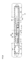
- Fig. 2 is a perspective view showing a configuration of power transmission device 50 employing a spiral type coil as the power transmission coil
- Fig. 3 is a perspective view showing a configuration of power transmission device 50 employing a wound type coil as the power transmission coil
- Fig. 4 is a diagram showing placement of various devices of power supply unit 300
- Fig. 5 is a sectional view taken along a line V-V in Fig. 2
- Fig. 6 is a sectional view corresponding to the view taken along line V-V in Fig. 2 , in a related art.
- Power transmission device 50 has power transmission unit 400 for transmitting power to power receiving device 10 in a noncontact manner, and power supply unit 300, connected to the external power supply, for supplying power to power transmission unit 400, as described above, and these power transmission unit 400 and power supply unit 300 are housed in a housing 600. Accordingly, power transmission device 50 according to this embodiment has a configuration in which power transmission unit 400 and power supply unit 300 are integrated.
- power supply unit 300 includes high frequency power device 310, power transmission ECU 320, and communication unit 322, as shown in Fig. 1 , and components configuring these devices are switching power supplies 701, 702 and 703, a PFC sub-board 704, a fan 705, a DC/RF unit 706, a 5V/15V power supply 707, a 24V power supply 708, a resonance capacitor 709, a fan 710, a heat sink 711, a fan 712, a heat sink 713, fans 714 and 715, a filter inductor 716, a filter capacitor 717, fans 718 and 719, a filter inductor 720, a filter capacitor 721, a SCU 722, an interface 723, an input controller 724, and the like.
- Switching power supplies 701, 702 and 703 configure an AC/DC unit
- filter inductors 716, 717 and 720, and filter capacitor 721 configure a filter unit
- DC/RF unit 706 configures a DC/RF unit.
- These devices are mounted on a bottom plate 610 configuring a bottom surface of housing 600.
- power supply unit 300 can be roughly classified into first devices disposed around power transmission unit 400, and second devices disposed between power transmission unit 400 and bottom plate 610 in a state where power transmission unit 400 and power supply unit 300 are mounted on the bottom plate of housing 600.
- the "around power transmission unit 400” means that an area (A1) from an end of ferrite core 460 defining an outer shape of power transmission unit 400 to the outside, as shown in Fig. 5 , and an area covered with ferrite core 460 in plan view is located at a position between power transmission unit 400 and bottom plate 610. These areas are similar to corresponding areas in power receiving unit 200 of power receiving device 10 described later.
- the first devices disposed around power transmission unit 400 are a high part 701a of switching power supply 701, FC sub-board 704, fan 705, fan 710, heat sink 711, fan 712, heat sink 713, fan 714, 715, filter inductor 716, filter capacitor 717, fans 718 and 719, filter inductor 720, and the like.
- the second devices disposed between power transmission unit 400 and bottom plate 610 are a low part 701b of switching power supply 701, 5V/15V power supply 707, 24V power supply 708, resonance capacitor 709, filter capacitor 721, interface 723, input controller 724, and the like.
- heights (H1, H2) of first devices 702a, 720, and the like from bottom plate 610 are higher than heights (H3, H4, H5) of second devices 702b, 708 and 721 from bottom plate 610.
- low part 701b is provided to be lower than high part 701a.
- the heights of the first devices disposed around power transmission unit 400 from bottom plate 610 are made higher than the heights of the second devices disposed between power transmission unit 400 and bottom plate 610 of housing 600. Consequently, a position of an upper surface of power transmission unit 400 located above the second devices is approximate to positions of the first devices disposed around power transmission unit 400, so that the upper surface of power transmission unit 400 can be inhibited from largely protruding upward. Consequently, even when wheels of the vehicle run on power transmission device 50, a load can be inhibited from concentrating on power transmission unit 400.
- power transmission device 50 In power transmission device 50 according to this embodiment, difference (unevenness) between the heights of the devices housed in housing 60 is reduced, and a whole of housing 600 is formed in a thin flat shape, so that a load is inhibited from concentrating on a particular part of an upper surface of housing 600.
- the first devices disposed around power transmission unit 400 and the second devices disposed between power transmission unit 400 and bottom plate 610, described above, are each an example, and are changed in accordance with a specification required for power transmission unit 400.
- power transmission device 50 in a case where power transmission unit 400 and power supply unit 300 are housed in housing 600, and power transmission unit 400 and power supply unit 300 are integrated, it is conceived that power transmission unit 400 is disposed on one side, and power supply unit 300 is disposed on the other side as shown in Fig. 6 .
- a center position CL1 of housing 600 that is the center of power transmission device 50 deviates from a center position CL2 of power transmission unit 400.
- a configuration in which the first devices disposed around power transmission unit 400 are disposed on both sides of power transmission unit 400 in a width direction of the vehicle (arrow W direction in the drawing) when viewed from an entry direction of the vehicle (arrow F direction in the drawing) is employed, as shown in Figs. 2, 3 and 5 .
- center position CL1 of housing 600 that is the center of power transmission device 50 coincides with center position CL2 of power transmission unit 400
- center position CL1 of housing 600 that is the center of power transmission device 50 does not always completely coincide with center position CL2 of power transmission unit 400.
- the configuration in which the first devices disposed around power transmission unit 400 are disposed on both sides of power transmission unit 400 in the width direction of the vehicle (arrow W direction in the drawing) when viewed from the entry direction of the vehicle (arrow F direction in the drawing) is employed.
- Fig. 7 is a diagram showing a direction of a magnetic flux M in wound type power transmission coil 450
- Fig. 8 is a sectional view taken along a line VIII-VIII in Fig. 7
- Fig. 9 is a diagram showing a direction of magnetic flux M in a case where placement of wound type power transmission coil 450 is changed by 90°.
- the heights of first devices disposed around power transmission unit 400 are made higher than the height of second devices disposed between power transmission unit 400 and bottom plate 610, similarly to the spiral type coil shown in Fig. 5 .
- a height (H1) of each of the first devices located in a direction orthogonal to a winding axis Al (arrow W direction in the drawing) from bottom plate 610 of housing 600 is made higher than heights (H3, H4 and H5) of the second devices from bottom plate 610 of housing 600.
- height (H4) of each of the first devices located in an axial direction of winding axis Al from bottom plate 610 of housing 600 is made lower than a height (H6) from bottom plate 610 of housing 600 to a lower surface of ferrite core 460.
- height (H4) of each of the first devices located in the axial direction of winding axis Al from bottom plate 610 of housing 600 is low by employing the above configuration.
- magnetic flux M generated in wound type power transmission coil 450 is inhibited from interlinking with the first devices located in F direction in the drawing, and temperatures of the first devices can be prevented from rising.
- Height (H1) of each of the first devices located in the direction orthogonal to winding axis Al (arrow W direction in the drawing) from bottom plate 610 of housing 600 is made higher than heights (H3, H5) of the second devices from bottom plate 610 of housing 600, so that difference (unevenness) between the heights of the devices housed in housing 60 is reduced, and a thin flat shape of the whole of housing 600 can be employed. As a result, even when wheels of the vehicle run on power transmission device 50, trampling force can be inhibited from concentrating on power transmission device 50.
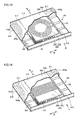
- Fig. 10 is a plan view of power transmission device 50A in this embodiment
- Fig. 11 is a sectional view taken along a line XI-XI in Fig. 10
- Fig. 12 is an enlarged partially sectional view of another mode of power transmission device 50A in this embodiment.
- An internal mechanism of power transmission device 50A according to this embodiment is the same as that of the above first embodiment, and is different in a configuration of a housing 600A employed in this embodiment.
- a heating value of the first devices disposed around a power transmission unit 400 is sometimes larger than a heating value of the second devices disposed between power transmission unit 400 and a bottom plate 610.
- a heating value of a high part 701a of a switching power supply 701 configuring an AC/DC unit, and a heat sink 713, filter inductors 716, 717, 720, and the like configuring a filter unit is larger than the heating value of the second devices disposed between power transmission unit 400 and bottom plate 610.
- heights H1 and H2 of first devices 702a and 720 from bottom plate 610 are higher than a height H7 of an upper surface of power transmission unit 400 from bottom plate 610.
- the upper surface of power transmission unit 400 means an upper end of power transmission coil 450.
- height H2 is set to be higher than height H7 by about 5 mm or more and about 10 mm or less.
- Housing 600A includes bottom plate 610 and a cover case 615.
- Cover case 615 includes a resin cover 616 disposed above power transmission unit 400, and metal covers 617 provided at adjacent positions in a width direction W of a vehicle with respect to resin cover 616.
- metal covers 617 are disposed on both sides in width direction W with respect to resin cover 616.
- Metal covers 617 each include an upper wall 618 covering upper surfaces of first devices 702a and 720, a side wall 619 covering side surfaces of first devices 702a and 720, and is formed of, for example, a metal material such as aluminum. First devices 702a and 720 are covered with metal covers 617 to be protected, and therefore even when a vehicle treads metal covers 617, a large load can be inhibited from being applied to first devices 702a and 720.
- a position of the upper surface of power transmission unit 400 is lower than a position of the upper surface of each of first devices 702a and 720, and therefore when metal covers 617 are trod, a large load is inhibited from being applied to power transmission unit 400.
- a length in width direction W of each of upper walls 618 is, for example, between about 180 mm and about 250 mm, inclusive, and a width of each upper wall 618 is formed to have at least a width of a general wheel. Consequently, even when the vehicle runs on power transmission device 50, wheels can be inhibited from pressing resin cover 616, and an excessive load can be inhibited from being applied to power transmission unit 400.
- Two metal covers 617 are provided on both end sides in width direction W of power transmission device 50, and formed so as to extend in a longitudinal direction of the vehicle. Therefore, even when the wheels run on from the vicinity of a corner in width direction W that is an front end of power transmission device 50, and further moves, metal covers 617 can protect the first devices.
- Housing 600A employs a cooling structure in which the first devices are held between a bottom plate 610 side of the first devices and a front surface 621 side opposite to bottom plate 610.
- An area where the first devices are held between bottom plate 610 side and front surface 621 side coincides with an area around power transmission unit 400, and the cooling structure is employed in each area Al of Fig. 11 .
- the cooling structure is formed by upper walls 618 of metal covers 617, side walls 619 of metal covers, and bottom plate 610.
- An aluminum plate excellent in heat radiation characteristics is used as bottom plate 610, and the first devices are mounted on bottom plate 610. Consequently, heat from the first devices having a large heating value is radiated from upper walls 618 to the outside, and heat is further satisfactorily radiated from bottom plate 610 that is a mounting surface for the first devices.
- metal covers 617 each have both a protective function of protecting the first devices, and a cooling function of the first devices.
- unevenness structures are formed by a plurality of grooves 620g. That is, grooves 620g are formed by upper walls 618 and side walls 619 of metal covers 617. Grooves 620g are formed so as to extend in a direction F as shown in Fig. 10 . Grooves 620g are provided, so that a surface area of a cover 620A is enlarged, and a contact area with the air is increased. Consequently, it is possible to enhance a heat radiation effect.
- a heat radiation heat 730 having a sufficient heat transfer characteristic is interposed between an upper surface of filter inductor 720 being an example of the first device, and a lower surface of front surface area 620Ap of cover 620A.
- unevenness structures using a plurality of grooves 620g are formed not only in a front surface side and a rear surface side of the first devices located around power transmission unit 400 but also in side surface areas 620As of cover 620A.
- cover 620A of power transmission device 50A the aluminum plate is used as bottom plate 610, the unevenness structures in which a plurality of grooves 620g are also formed on the surfaces of aluminum plates in front surface areas 620Ap on a front surface side and side surface areas 620As are employed. Consequently, it is possible to effectively discharge head radiated from the first devices to the outside. As a result, it is possible to inhibit temperature rise of the first devices disposed around power transmission unit 400.
- the aluminum materials having sufficient heat radiation characteristics are used, unevenness shapes in which the plurality of grooves 620g are formed are provided on the front surface side and the side surface sides, and heat radiation sheet 730 is furthermore used.
- the present invention is not limited to this configuration.
- Fig. 12 it is possible to enhance heat radiation performance, and to inhibit temperature rise of the first devices located around power transmission unit 400, by providing only a flat aluminum plate without providing grooves 620g in front surface areas 620Ap on the front surface side and side surface areas 620As. Any other materials having sufficient heat radiation characteristics may be used, and the material is not limited to an aluminum material.
- Fig. 13 is a perspective view showing a configuration of a power receiving device 10 employing a spiral type power receiving coil 250
- Fig. 14 is a perspective view showing a configuration of a power receiving device 10 employing a wound type power receiving coil 250.
- Power receiving device 10 in each of Figs. 13 and 14 is illustration of a state where a facility side in a case where power receiving device 10 is mounted in a vehicle is an upper side (illustration of a state turned upside down). Accordingly, the top in the drawing is a lower side (ground side) in the following description.
- Power receiving device 10 basically has a configuration similar to the configurations of the above power transmission devices 50 and 50A, and has a power receiving unit 200 for receiving power from power transmission device 50 in a noncontact manner, an apparatus unit 110 provided between power receiving unit 200 and a battery 15 for storing power received by power receiving unit 200.
- Power receiving unit 200 and apparatus unit 110 are housed in any of housings 600 and 600A having configurations similar to the housings used in the above power transmission devices 50 and 50A. Accordingly, power receiving device 10 according to this embodiment has a configuration in which power receiving unit 200 and apparatus unit 100 are integrated.
- Apparatus unit 110 has a capacitor 120, a rectifier 130, a DC/DC converter 140, and the like.
- First devices disposed around power receiving unit 200 are rectifier 130, DC/DC converter 140, and the like, and second devices disposed between power receiving unit 200 and a bottom plate 610 of housing 600 are capacitor 120 and the like.
- the first devices disposed around power receiving unit 200 and the second devices disposed between power receiving unit 200 and a bottom plate 610 of housing 600, described above, are each an example, and are changed in accordance with a specification required for power receiving unit 200.
- heights of the first devices disposed around power receiving unit 200 are higher (longer) than heights of the second devices disposed between power receiving unit 200 and bottom plate 610 of housing 600 (distance from bottom plate 610 to lower surfaces of the second devices). Consequently, power receiving unit 200 disposed on a lower surface side of the second devices can be inhibited from protruding downward, difference (unevenness) between the heights of the devices housed in housing 60 is reduced, and a thin flat shape of the whole of housing 600 can be employed.
- power receiving unit 200 can be inhibited from coming into contact with unevenness (e.g., railroad crossing) on the ground, a falling object on the ground, or other obstacle, and contact force can be inhibited from concentrating even in a case where power receiving unit 200 comes into contact with the unevenness or the like.
- unevenness e.g., railroad crossing
- a height of each of the first devices located in a direction orthogonal to a winding axis Al from bottom plate 610 of housing 600 is made higher than a height of each of the second devices from bottom plate 610 of housing 600, and a height of each of the first devices located in an axial direction of winding axis Al from bottom plate 610 of housing 600 is made lower than a height from bottom plate 610 of housing 600 to a lower surface of a ferrite core 260.
- a magnetic flux M generated in wound type power receiving coil 250 is inhibited from interlinking with the first devices located in an F direction in the drawing, and temperatures of the first devices can be prevented from rising.
- housing 600 includes bottom plate 610, and a cover 620.
- Cover 620 includes a resin cover 616 disposed above power transmission unit 400, and metal covers 617 provided at adjacent positions in width direction W of the vehicle with respect to resin cover 616.
- Metal covers 617 each include a lower wall 618A covering the lower surfaces of the first devices, a side wall 619 covering side surfaces of the first devices 702a, 720, and is formed of, for example, a metal material such as aluminum.
- the first devices are protected by metal covers 617, and therefore the first devices can be inhibited from being damaged. Furthermore, the lower surface of power receiving unit 200 is located above the lower surfaces of the first devices and lower surfaces of metal covers 617, and therefore a large load can be inhibited from being applied to power receiving unit 200.
- a cooling structure in which the first devices are cooled from upper and lower surfaces by lower walls 618A and bottom plate 610 is formed. Both lower walls 618A and side walls 619 are formed with grooves 620g (unevenness structure) extending in a direction F. Grooves 620g improve a cooling efficiency.
- a heating value of the first devices disposed around power receiving unit 200 is larger than a heating value of the second devices disposed between power receiving unit 200 and bottom plate 610 of housing 600, the cooling structure shown in Figs. 10 to 12 is applied to housing 600, so that heat radiated from the first devices can be effectively discharged to the outside. As a result, temperatures of the first devices located around power receiving unit 200 can be inhibited from rising.
- a power transmission device (50) for transmitting power to a power receiving device (10) in a noncontact manner including: a power transmission unit (400) for transmitting power to the power receiving device (10) in a noncontact manner; a power supply unit (300), connected to an external power supply, for supplying power to the power transmission unit (400), and a housing (600) housing the power transmission unit (400) and the power supply unit (300), wherein the power supply unit (300) includes first devices (702a, 720) disposed around the power transmission unit (400), and a second device (708) disposed between the power transmission unit (400) and a bottom surface (610), in a state where the power transmission unit (400) and the power supply unit (300) are mounted on the bottom surface (610) of the housing (600, 600A), and a height of each of the first devices (702a, 720) from the bottom surface (610) is higher than a height of the second device (708) from the bottom surface (610).
Abstract
Description
- This nonprovisional application is based on Japanese Patent Application No.
2014-120366 filed on June 11, 2014 - The present invention relates to a power transmission device for transmitting power to a power receiving device in a noncontact manner, and a power receiving device for receiving power from a power transmission device in a noncontact manner.
- As disclosed in Japanese Patent Laying-Open Nos.
2013-154815 2013-146154 2013-146148 2013-110822 2013-126327 2014-011939 2014-011332 - According to the configuration of each of the above prior art documents, in the power transmission device, a high frequency power source and the like need to be provided in addition to the capacitor and the coil unit. Therefore, a management side of a charging station needs to install not only a power transmission device but also a high frequency power source.
- In the power transmission device described in Japanese Patent Laying-Open No.
2014-011939 - On the other hand, when the peripheral devices are simply disposed on the lower surface side of the coil unit, a height of the coil unit becomes higher than a height of the capacitor disposed around the coil unit, and the coil unit largely protrudes upward. In a state where an upper surface of the coil unit relatively protrudes upward, when a vehicle runs on the power transmission device, a large load is applied to the coil unit from wheels. A problem that the coil unit includes a ferrite core, and is damaged due to the application of the large load is caused.
- Also in the power receiving device, in a case where the coil unit largely protrudes downward beyond devices disposed around the coil unit, a problem that when the power receiving device comes into contact with unevenness (e.g., a railroad crossing) of the ground, a falling object on the ground, or other obstacle, the coil unit is damaged is caused.
- The present invention has been made in view of the above problems, and an object of the present invention is to provide a power transmission device and a power receiving device, each of which suppresses increase in size in a case where peripheral devices are housed in a single housing to be integrated, and suppresses damage of a coil unit when external power from wheels of a vehicle is applied.
- According to this power transmission device, the power supply unit includes first devices disposed around the power transmission unit, and a second device disposed between the power transmission unit and the bottom surface of the housing, in a state where the power receiving unit and the apparatus unit are mounted on the bottom surface of the housing, and a height of each of the first devices from the bottom surface of the housing is higher than a height of the second device from the bottom surface.
- According to this power transmission device, an upper surface of the power transmission unit is approximate to a height of an upper surface of each of the first devices located around the power transmission unit, so that the upper surface of the power transmission unit can be inhibited from protruding upward. Consequently, even when wheels of a vehicle run on the power transmission device, a large load can be inhibited from being applied to the power transmission unit. Furthermore, the second device is disposed on a lower surface of the power transmission unit, the height of each first device disposed around the power transmission unit is made higher, and installation areas of the first devices are reduced, so that an installation area of a whole of the power transmission device can be inhibited from increasing.
- According to this power receiving device, the apparatus unit includes first devices disposed around the power receiving unit, and a second device disposed between the power receiving unit and a bottom surface of the housing, in a state where the power receiving unit and the apparatus unit are mounted on the bottom surface of the housing, and a height of each of the first devices from the bottom surface of the housing is higher than a height of the second device from the bottom surface of the housing.
- According to this power receiving device, the power receiving unit is inhibited from largely protruding downward beyond the first devices located around the power receiving unit. Consequently, even when the power receiving device interferes with the ground, a large load is inhibited from being applied to the power receiving unit. Furthermore, the second device is disposed on a lower surface of the power receiving unit, and the height of each first device disposed around the power receiving unit is made higher, and installation areas of the first devices are reduced, so that an installation area of a whole of the power receiving device is inhibited from increasing.
- The foregoing and other objects, features, aspects and advantages of the present invention will become more apparent from the following detailed description of the present invention when taken in conjunction with the accompanying drawings.
-
-
Fig. 1 is a diagram showing a power transmission system in a first embodiment. -
Fig. 2 is a perspective view showing a configuration of a power transmission device employing a spiral type coil, in the first embodiment. -
Fig. 3 is a perspective view showing a configuration of a power transmission device employing a wound type coil, in the first embodiment. -
Fig. 4 is a diagram showing placement of various devices of a power supply unit of the power transmission device in the first embodiment. -
Fig. 5 is a sectional view taken along a line V-V inFig. 2 . -
Fig. 6 is a sectional view corresponding to the view taken along line V-V inFig. 2 , in a related art. -
Fig. 7 is a diagram showing a direction of a magnetic flux in the wound type coil of the power transmission device. -
Fig. 8 is a sectional view taken along a line VIII-VIII inFig. 7 . -
Fig. 9 is a diagram showing a direction of a magnetic flux in a case where placement of the wound type coil of the power transmission device is changed. -
Fig. 10 is a plan view of a power transmission device in a second embodiment. -
Fig. 11 is a sectional view taken along a line XI-XI inFig. 10 . -
Fig. 12 is an enlarged partially sectional view of another mode of the power transmission device in the second embodiment. -
Fig. 13 is a perspective view showing a configuration of a power receiving device employing a spiral type coil, in a third embodiment. -
Fig. 14 is a perspective view showing a configuration of a power receiving device employing a wound type coil, in the third embodiment. - Exemplified embodiments based on the present invention are hereinafter described with reference to the drawings. In the following embodiments, when a number, an amount or the like is mentioned, the scope of the present invention is not necessarily limited to the number, the amount or the like, unless otherwise specified. The same reference numerals denote the same or corresponding components, and overlapping description may not be repeated. It is intended from the beginning to appropriately combine and use the configurations in the embodiments. In the drawings, illustration is not performed at actual dimension ratios, but performed at the partially different ratios in order to facilitate understanding of the structure.
- A configuration of a power transmission device installed on a facility side
- (parking area or the like), mainly described below, is applicable also to a power receiving device mounted on a vehicle side. In the power transmission device, a bottom surface side means the facility (ground) side, and a front surface side means a power receiving device (vehicle) side. On the other hand, in the power receiving device, a bottom surface side means the vehicle side, and a front surface side means a power transmission device (ground) side.
- In each of the drawings used below, a direction shown by an arrow F in the drawing indicates an entry direction and an advancing direction (including retreating) of a vehicle, and a direction shown by an arrow W in the drawing indicates a width direction of the vehicle.
- With reference to
Fig. 1 , apower transmission system 1000 for transmitting power in a noncontact manner will be described.Power transmission system 1000 includes apower receiving device 10 mounted on anelectric vehicle 100, and apower transmission device 50 installed on a facility side such as a parking area.Electric vehicle 100 includespower receiving device 10 and avehicle body 105. -
Power receiving device 10 includes apower receiving unit 200, and anapparatus unit 110 provided betweenpower receiving unit 200 and abattery 150 serving a storage device for storing power received bypower receiving unit 200.Power receiving unit 200 has apower receiving coil 250 and a plate shapedferrite core 260. As described later, aspower receiving coil 250, any of a spiral type coil (seeFig. 2 ) and a wound type coil (seeFig. 3 ) may be employed.Fig. 1 shows spiral typepower receiving coil 250.Apparatus unit 110 has acapacitor 120, arectifier 130, a DC/DC converter 140, and the like.Power receiving coil 250 and acapacitor 220 are connected in series in the drawing, but may be connected in parallel. -
Vehicle body 105 includes battery 15 connected to DC/DC converter 140 ofapparatus unit 100, apower control unit 160, amotor unit 170, acommunication unit 180, and the like. - The number of turns of
power receiving coil 250 is appropriately set so as to increase a distance betweenpower receiving coil 250 and apower transmission coil 450 described later, a Q value (e.g., Q ≥ 100) showing resonance strength ofpower receiving coil 250 andpower transmission coil 450, a coupling coefficient κ showing a coupling degree of the resonance strength, and the like.Power receiving coil 250 is connected torectifier 130.Rectifier 130 converts an AC current supplied frompower receiving unit 200 into a DC current, to supply the converted DC current to DC/DC converter 140. -
Power transmission device 50 includes apower transmission unit 400 and apower supply unit 300.Power transmission unit 400 haspower transmission coil 450 and a plate shapedferrite core 460. Aspower transmission coil 450, any of a spiral type coil (seeFig. 2 ) and a wound type coil (seeFig. 3 ) may be employed.Fig. 1 shows spiral typepower transmission coil 450.Power supply unit 300 includes acapacitor 420, a highfrequency power device 310, apower transmission ECU 320, and acommunication unit 322.Power supply unit 300 is detachably connected to anAC power supply 330 by using anoutlet plug 340 or the like.Power transmission coil 450 andcapacitor 420 are connected in series in the drawing, but may be connected in parallel. - High
frequency power device 310 converts power received fromAC power supply 330 into high-frequency power, to supply the converted high-frequency power topower transmission coil 450.Power transmission coil 450 transmits power to power receivingcoil 250 ofpower receiving unit 200 in a noncontact manner by electromagnetic induction. - With reference to
Figs. 2 to 6 , a detailed configuration ofpower transmission device 50 according to this embodiment will be described.Fig. 2 is a perspective view showing a configuration ofpower transmission device 50 employing a spiral type coil as the power transmission coil,Fig. 3 is a perspective view showing a configuration ofpower transmission device 50 employing a wound type coil as the power transmission coil,Fig. 4 is a diagram showing placement of various devices ofpower supply unit 300,Fig. 5 is a sectional view taken along a line V-V inFig. 2 , andFig. 6 is a sectional view corresponding to the view taken along line V-V inFig. 2 , in a related art. -
Power transmission device 50 haspower transmission unit 400 for transmitting power to power receivingdevice 10 in a noncontact manner, andpower supply unit 300, connected to the external power supply, for supplying power topower transmission unit 400, as described above, and thesepower transmission unit 400 andpower supply unit 300 are housed in ahousing 600. Accordingly,power transmission device 50 according to this embodiment has a configuration in whichpower transmission unit 400 andpower supply unit 300 are integrated. - With reference to
Figs. 2 and. 3 , in this embodiment,power supply unit 300 includes highfrequency power device 310,power transmission ECU 320, andcommunication unit 322, as shown inFig. 1 , and components configuring these devices are switchingpower supplies PFC sub-board 704, afan 705, a DC/RF unit 706, a 5V/15V power supply 707, a24V power supply 708, aresonance capacitor 709, afan 710, aheat sink 711, afan 712, aheat sink 713,fans filter inductor 716, afilter capacitor 717,fans filter inductor 720, afilter capacitor 721, aSCU 722, aninterface 723, aninput controller 724, and the like. Switching power supplies 701, 702 and 703 configure an AC/DC unit,filter inductors filter capacitor 721 configure a filter unit, and DC/RF unit 706 configures a DC/RF unit. These devices are mounted on abottom plate 610 configuring a bottom surface ofhousing 600. - With reference to
Figs. 4 and5 , in this embodiment,power supply unit 300 can be roughly classified into first devices disposed aroundpower transmission unit 400, and second devices disposed betweenpower transmission unit 400 andbottom plate 610 in a state wherepower transmission unit 400 andpower supply unit 300 are mounted on the bottom plate ofhousing 600. - Herein, the "around
power transmission unit 400" means that an area (A1) from an end offerrite core 460 defining an outer shape ofpower transmission unit 400 to the outside, as shown inFig. 5 , and an area covered withferrite core 460 in plan view is located at a position betweenpower transmission unit 400 andbottom plate 610. These areas are similar to corresponding areas inpower receiving unit 200 ofpower receiving device 10 described later. - The first devices disposed around
power transmission unit 400 are ahigh part 701a of switchingpower supply 701, FC sub-board 704,fan 705,fan 710,heat sink 711,fan 712,heat sink 713,fan filter inductor 716,filter capacitor 717,fans filter inductor 720, and the like. - The second devices disposed between
power transmission unit 400 andbottom plate 610 are alow part 701b of switchingpower supply 701, 5V/15V power supply 707,24V power supply 708,resonance capacitor 709,filter capacitor 721,interface 723,input controller 724, and the like. - Herein, as shown in
Fig. 5 , heights (H1, H2) offirst devices bottom plate 610 are higher than heights (H3, H4, H5) ofsecond devices bottom plate 610. Also in switchingpower supply 701 which is the same device,low part 701b is provided to be lower thanhigh part 701a. - Thus, the heights of the first devices disposed around
power transmission unit 400 frombottom plate 610 are made higher than the heights of the second devices disposed betweenpower transmission unit 400 andbottom plate 610 ofhousing 600. Consequently, a position of an upper surface ofpower transmission unit 400 located above the second devices is approximate to positions of the first devices disposed aroundpower transmission unit 400, so that the upper surface ofpower transmission unit 400 can be inhibited from largely protruding upward. Consequently, even when wheels of the vehicle run onpower transmission device 50, a load can be inhibited from concentrating onpower transmission unit 400. - In
power transmission device 50 according to this embodiment, difference (unevenness) between the heights of the devices housed in housing 60 is reduced, and a whole ofhousing 600 is formed in a thin flat shape, so that a load is inhibited from concentrating on a particular part of an upper surface ofhousing 600. - The first devices disposed around
power transmission unit 400 and the second devices disposed betweenpower transmission unit 400 andbottom plate 610, described above, are each an example, and are changed in accordance with a specification required forpower transmission unit 400. - Herein, in
power transmission device 50, in a case wherepower transmission unit 400 andpower supply unit 300 are housed inhousing 600, andpower transmission unit 400 andpower supply unit 300 are integrated, it is conceived thatpower transmission unit 400 is disposed on one side, andpower supply unit 300 is disposed on the other side as shown inFig. 6 . - However, in a case where
power transmission unit 400 andpower supply unit 300 are disposed as shown inFig. 6 , a center position CL1 ofhousing 600 that is the center ofpower transmission device 50 deviates from a center position CL2 ofpower transmission unit 400. - Therefore, in this embodiment, a configuration in which the first devices disposed around
power transmission unit 400 are disposed on both sides ofpower transmission unit 400 in a width direction of the vehicle (arrow W direction in the drawing) when viewed from an entry direction of the vehicle (arrow F direction in the drawing) is employed, as shown inFigs. 2, 3 and5 . - In this embodiment, as the most preferable mode, a configuration in which center position CL1 of
housing 600 that is the center ofpower transmission device 50 coincides with center position CL2 ofpower transmission unit 400 is employed. However, center position CL1 ofhousing 600 that is the center ofpower transmission device 50 does not always completely coincide with center position CL2 ofpower transmission unit 400. When compared to the configuration shown inFig. 6 , the configuration in which the first devices disposed aroundpower transmission unit 400 are disposed on both sides ofpower transmission unit 400 in the width direction of the vehicle (arrow W direction in the drawing) when viewed from the entry direction of the vehicle (arrow F direction in the drawing) is employed. - By employing this configuration, it is possible to guide (drive) the vehicle based on center position CL1 of
housing 600 in a case where the vehicle mounted withpower receiving device 10 is aligned withpower transmission device 50, and it is possible to easily alignpower receiving device 10 withpower transmission device 50. - With reference to
Figs. 7 to 9 , a case where a wound type power transmission coil 450 (seeFig. 3 ) is used inpower transmission unit 400 ofpower transmission device 50 will be described.Fig. 7 is a diagram showing a direction of a magnetic flux M in wound typepower transmission coil 450,Fig. 8 is a sectional view taken along a line VIII-VIII inFig. 7 , andFig. 9 is a diagram showing a direction of magnetic flux M in a case where placement of wound typepower transmission coil 450 is changed by 90°. - Also in a case where wound type
power transmission coil 450 shown inFig. 3 is employed, the heights of first devices disposed aroundpower transmission unit 400 are made higher than the height of second devices disposed betweenpower transmission unit 400 andbottom plate 610, similarly to the spiral type coil shown inFig. 5 . - With reference to
Figs. 5 and7 , in this embodiment, a height (H1) of each of the first devices located in a direction orthogonal to a winding axis Al (arrow W direction in the drawing) frombottom plate 610 ofhousing 600 is made higher than heights (H3, H4 and H5) of the second devices frombottom plate 610 ofhousing 600. With reference toFigs. 7 and8 , height (H4) of each of the first devices located in an axial direction of winding axis Al frombottom plate 610 ofhousing 600 is made lower than a height (H6) frombottom plate 610 ofhousing 600 to a lower surface offerrite core 460. - As shown in
Fig. 7 , height (H4) of each of the first devices located in the axial direction of winding axis Al frombottom plate 610 ofhousing 600 is low by employing the above configuration. As a result, magnetic flux M generated in wound typepower transmission coil 450 is inhibited from interlinking with the first devices located in F direction in the drawing, and temperatures of the first devices can be prevented from rising. - On the other hand, as shown in
Fig. 9 , in a case where placement of wound typepower transmission coil 450 is changed by 90° (axial direction of winding axis Al coincides with the width direction W of the vehicle), the high first devices exists in the axial direction of winding axis Al. As a result, magnetic flux M generated in wound typepower transmission coil 450 easily interlinks with the first devices located in direction W in the drawing, there is a concern about rise in the temperatures of the first devices. - Height (H1) of each of the first devices located in the direction orthogonal to winding axis Al (arrow W direction in the drawing) from
bottom plate 610 ofhousing 600 is made higher than heights (H3, H5) of the second devices frombottom plate 610 ofhousing 600, so that difference (unevenness) between the heights of the devices housed in housing 60 is reduced, and a thin flat shape of the whole ofhousing 600 can be employed. As a result, even when wheels of the vehicle run onpower transmission device 50, trampling force can be inhibited from concentrating onpower transmission device 50. - With reference to
Figs. 10 to 12 , apower transmission device 50A according to this embodiment will be now described.Fig. 10 is a plan view ofpower transmission device 50A in this embodiment,Fig. 11 is a sectional view taken along a line XI-XI inFig. 10 , andFig. 12 is an enlarged partially sectional view of another mode ofpower transmission device 50A in this embodiment. - An internal mechanism of
power transmission device 50A according to this embodiment is the same as that of the above first embodiment, and is different in a configuration of ahousing 600A employed in this embodiment. A heating value of the first devices disposed around apower transmission unit 400 is sometimes larger than a heating value of the second devices disposed betweenpower transmission unit 400 and abottom plate 610. For example, a heating value of ahigh part 701a of a switchingpower supply 701 configuring an AC/DC unit, and aheat sink 713,filter inductors power transmission unit 400 andbottom plate 610. - With reference to
Figs. 10 and11 , inpower transmission device 50A according to this embodiment, heights H1 and H2 offirst devices bottom plate 610 are higher than a height H7 of an upper surface ofpower transmission unit 400 frombottom plate 610. The upper surface ofpower transmission unit 400 means an upper end ofpower transmission coil 450. For example, height H2 is set to be higher than height H7 by about 5 mm or more and about 10 mm or less. -
Housing 600A includesbottom plate 610 and a cover case 615. Cover case 615 includes aresin cover 616 disposed abovepower transmission unit 400, and metal covers 617 provided at adjacent positions in a width direction W of a vehicle with respect toresin cover 616. In this embodiment, metal covers 617 are disposed on both sides in width direction W with respect toresin cover 616. - Metal covers 617 each include an
upper wall 618 covering upper surfaces offirst devices side wall 619 covering side surfaces offirst devices First devices first devices - A position of the upper surface of
power transmission unit 400 is lower than a position of the upper surface of each offirst devices power transmission unit 400. A length in width direction W of each ofupper walls 618 is, for example, between about 180 mm and about 250 mm, inclusive, and a width of eachupper wall 618 is formed to have at least a width of a general wheel. Consequently, even when the vehicle runs onpower transmission device 50, wheels can be inhibited from pressingresin cover 616, and an excessive load can be inhibited from being applied topower transmission unit 400. - Two metal covers 617 are provided on both end sides in width direction W of
power transmission device 50, and formed so as to extend in a longitudinal direction of the vehicle. Therefore, even when the wheels run on from the vicinity of a corner in width direction W that is an front end ofpower transmission device 50, and further moves, metal covers 617 can protect the first devices. -
Housing 600A employs a cooling structure in which the first devices are held between abottom plate 610 side of the first devices and afront surface 621 side opposite tobottom plate 610. An area where the first devices are held betweenbottom plate 610 side andfront surface 621 side coincides with an area aroundpower transmission unit 400, and the cooling structure is employed in each area Al ofFig. 11 . - Specifically, the cooling structure is formed by
upper walls 618 of metal covers 617,side walls 619 of metal covers, andbottom plate 610. An aluminum plate excellent in heat radiation characteristics is used asbottom plate 610, and the first devices are mounted onbottom plate 610. Consequently, heat from the first devices having a large heating value is radiated fromupper walls 618 to the outside, and heat is further satisfactorily radiated frombottom plate 610 that is a mounting surface for the first devices. Thus, metal covers 617 each have both a protective function of protecting the first devices, and a cooling function of the first devices. - In front surface areas 620Ap located around
power transmission unit 400 in outer surfaces of metal covers 617, unevenness structures are formed by a plurality ofgrooves 620g. That is,grooves 620g are formed byupper walls 618 andside walls 619 of metal covers 617.Grooves 620g are formed so as to extend in a direction F as shown inFig. 10 .Grooves 620g are provided, so that a surface area of acover 620A is enlarged, and a contact area with the air is increased. Consequently, it is possible to enhance a heat radiation effect. In this embodiment, in order to facilitate heat radiation from the first devices, aheat radiation heat 730 having a sufficient heat transfer characteristic is interposed between an upper surface offilter inductor 720 being an example of the first device, and a lower surface of front surface area 620Ap ofcover 620A. - Furthermore, in this embodiment, unevenness structures using a plurality of
grooves 620g are formed not only in a front surface side and a rear surface side of the first devices located aroundpower transmission unit 400 but also in side surface areas 620As ofcover 620A. - Thus, in
cover 620A ofpower transmission device 50A according to this embodiment, the aluminum plate is used asbottom plate 610, the unevenness structures in which a plurality ofgrooves 620g are also formed on the surfaces of aluminum plates in front surface areas 620Ap on a front surface side and side surface areas 620As are employed. Consequently, it is possible to effectively discharge head radiated from the first devices to the outside. As a result, it is possible to inhibit temperature rise of the first devices disposed aroundpower transmission unit 400. - In this embodiment, the aluminum materials having sufficient heat radiation characteristics are used, unevenness shapes in which the plurality of
grooves 620g are formed are provided on the front surface side and the side surface sides, andheat radiation sheet 730 is furthermore used. However, the present invention is not limited to this configuration. - As shown in
Fig. 12 , it is possible to enhance heat radiation performance, and to inhibit temperature rise of the first devices located aroundpower transmission unit 400, by providing only a flat aluminum plate without providinggrooves 620g in front surface areas 620Ap on the front surface side and side surface areas 620As. Any other materials having sufficient heat radiation characteristics may be used, and the material is not limited to an aluminum material. - With reference to
Figs. 13 and 14 , a configuration of apower receiving device 10 will be described as a third embodiment.Fig. 13 is a perspective view showing a configuration of apower receiving device 10 employing a spiral typepower receiving coil 250, andFig. 14 is a perspective view showing a configuration of apower receiving device 10 employing a wound typepower receiving coil 250.Power receiving device 10 in each ofFigs. 13 and 14 is illustration of a state where a facility side in a case wherepower receiving device 10 is mounted in a vehicle is an upper side (illustration of a state turned upside down). Accordingly, the top in the drawing is a lower side (ground side) in the following description. -
Power receiving device 10 basically has a configuration similar to the configurations of the abovepower transmission devices power receiving unit 200 for receiving power frompower transmission device 50 in a noncontact manner, anapparatus unit 110 provided betweenpower receiving unit 200 and a battery 15 for storing power received bypower receiving unit 200.Power receiving unit 200 andapparatus unit 110 are housed in any ofhousings power transmission devices power receiving device 10 according to this embodiment has a configuration in whichpower receiving unit 200 andapparatus unit 100 are integrated. -
Apparatus unit 110 has acapacitor 120, arectifier 130, a DC/DC converter 140, and the like. First devices disposed aroundpower receiving unit 200 arerectifier 130, DC/DC converter 140, and the like, and second devices disposed betweenpower receiving unit 200 and abottom plate 610 ofhousing 600 arecapacitor 120 and the like. - The first devices disposed around
power receiving unit 200 and the second devices disposed betweenpower receiving unit 200 and abottom plate 610 ofhousing 600, described above, are each an example, and are changed in accordance with a specification required forpower receiving unit 200. - Thus, heights of the first devices disposed around power receiving unit 200 (distances from
bottom plate 610 to lower surfaces of the first devices) are higher (longer) than heights of the second devices disposed betweenpower receiving unit 200 andbottom plate 610 of housing 600 (distance frombottom plate 610 to lower surfaces of the second devices). Consequently,power receiving unit 200 disposed on a lower surface side of the second devices can be inhibited from protruding downward, difference (unevenness) between the heights of the devices housed in housing 60 is reduced, and a thin flat shape of the whole ofhousing 600 can be employed. - As a result, even in a case where
power receiving device 10 is mounted on a vehicle side, it is possible to reduce a protruding amount ofpower receiving unit 200 from the vehicle side to the lower side (power transmission side). Consequently,power receiving unit 200 can be inhibited from coming into contact with unevenness (e.g., railroad crossing) on the ground, a falling object on the ground, or other obstacle, and contact force can be inhibited from concentrating even in a case wherepower receiving unit 200 comes into contact with the unevenness or the like. - Similarly to a case of
power transmission device 50 shown inFig. 6 , by employing the configuration in which the first devices disposed aroundpower receiving unit 200 are disposed on both sides ofpower receiving unit 200 in a width direction of the vehicle (arrow W direction in the drawing) when viewed from an advancing direction of the vehicle (arrow F direction in the drawing), it is possible to easily alignpower receiving device 10 withpower transmission device 50 when the vehicle is guided (driven) topower transmission device 50. - Similarly to a case of
power transmission device 50 shown inFigs. 7 to 9 , in a case where wound typepower receiving coil 250 is used, in the first devices disposed aroundpower receiving unit 200, a height of each of the first devices located in a direction orthogonal to a winding axis Al frombottom plate 610 ofhousing 600 is made higher than a height of each of the second devices frombottom plate 610 ofhousing 600, and a height of each of the first devices located in an axial direction of winding axis Al frombottom plate 610 ofhousing 600 is made lower than a height frombottom plate 610 ofhousing 600 to a lower surface of aferrite core 260. - Consequently, a magnetic flux M generated in wound type
power receiving coil 250 is inhibited from interlinking with the first devices located in an F direction in the drawing, and temperatures of the first devices can be prevented from rising. - In
power receiving device 10, lower surfaces of the first devices are located lower than a lower surface ofpower receiving unit 200. Also inpower receiving device 10,housing 600 includesbottom plate 610, and acover 620. Cover 620 includes aresin cover 616 disposed abovepower transmission unit 400, and metal covers 617 provided at adjacent positions in width direction W of the vehicle with respect toresin cover 616. Metal covers 617 each include alower wall 618A covering the lower surfaces of the first devices, aside wall 619 covering side surfaces of thefirst devices - Consequently, when a projection on the ground comes into contact with
power receiving device 10, the first devices are protected by metal covers 617, and therefore the first devices can be inhibited from being damaged. Furthermore, the lower surface ofpower receiving unit 200 is located above the lower surfaces of the first devices and lower surfaces of metal covers 617, and therefore a large load can be inhibited from being applied topower receiving unit 200. - Also in
power receiving device 10, a cooling structure in which the first devices are cooled from upper and lower surfaces bylower walls 618A andbottom plate 610 is formed. Bothlower walls 618A andside walls 619 are formed withgrooves 620g (unevenness structure) extending in adirection F. Grooves 620g improve a cooling efficiency. - Also in
power receiving device 10, since a heating value of the first devices disposed aroundpower receiving unit 200 is larger than a heating value of the second devices disposed betweenpower receiving unit 200 andbottom plate 610 ofhousing 600, the cooling structure shown inFigs. 10 to 12 is applied tohousing 600, so that heat radiated from the first devices can be effectively discharged to the outside. As a result, temperatures of the first devices located aroundpower receiving unit 200 can be inhibited from rising. - Although the present invention has been described and illustrated in detail, it is clearly understood that the same is by way of illustration and example only and is not to be taken by way of limitation, the scope of the present invention being interpreted by the terms of the appended claims.
- A power transmission device (50) for transmitting power to a power receiving device (10) in a noncontact manner, including: a power transmission unit (400) for transmitting power to the power receiving device (10) in a noncontact manner; a power supply unit (300), connected to an external power supply, for supplying power to the power transmission unit (400), and a housing (600) housing the power transmission unit (400) and the power supply unit (300), wherein the power supply unit (300) includes first devices (702a, 720) disposed around the power transmission unit (400), and a second device (708) disposed between the power transmission unit (400) and a bottom surface (610), in a state where the power transmission unit (400) and the power supply unit (300) are mounted on the bottom surface (610) of the housing (600, 600A), and a height of each of the first devices (702a, 720) from the bottom surface (610) is higher than a height of the second device (708) from the bottom surface (610).
Claims (12)
- A power transmission device (50) for transmitting power to a power receiving device (10) in a noncontact manner, comprising:a power transmission unit (400), including a ferrite core (460) and a power transmission coil (450), for transmitting power to said power receiving device (10) in a noncontact manner;a power supply unit (300), connected to an external power supply, for supplying power to said power transmission unit (400); anda housing (600, 600A) housing said power transmission unit (400) and said power supply unit (300), whereinsaid power supply unit (300) includes first devices (702a, 720) disposed around said power transmission unit (400), and a second device (708) disposed between said power transmission unit (400) and a bottom surface (610) of said housing (600, 600A), in a state where said power transmission unit (400) and said power supply unit (300) are mounted on said bottom surface (610) of said housing (600, 600A), anda height of each of said first devices (702a, 720) from said bottom surface (610) of said housing (600, 600A) is higher than a height of said second device (708) from said bottom surface (610) of said housing (600, 600A).
- The power transmission device according to claim 1, wherein
said power transmission device transmits power to said power receiving device (10) in a state of facing said power receiving device (10) mounted on a vehicle,
the height of each of said first devices (702a, 720) from said bottom surface (610) of said housing (600A) is higher than a height of said power transmission unit from said bottom surface (610) of said housing (600A),
said first devices (702a, 720) are disposed adjacent to each other on both sides in a width direction of said vehicle with respect to said power transmission unit (400), in a state where said power transmission device and said power receiving device (10) face each other, and
said housing (600A) includes metal covers (617) disposed so as to cover upper surfaces and side surfaces of said first devices (702a, 720). - The power transmission device according to claim 1 or 2, wherein
a heating value of said first devices (702a, 720) disposed around said power transmission unit (400) is larger than a heating value of the second device (708) disposed between said power transmission unit (400) and said bottom surface (610) of said housing (600, 600A), and
said housing (600, 600A) includes a cooling structure in which said first devices (702a, 720) are held between a side of said bottom surface (610) of said housing (600, 600A), and a side of a front surface (621) of said housing (600, 600A) opposite to said bottom surface (610). - The power transmission device according to claim 3, wherein
said housing (600A) includes metal covers (617) disposed so as to cover said first devices (702a, 720), and a metal bottom plate (610) mounted with said first devices (702a, 720),
said metal covers (617) have upper walls (618) to radiate heat from upper surfaces of said first devices (702a, 720), and
said cooling structure is formed by said metal cover (617) and said bottom plate (610), and said metal cover (617) is formed with an unevenness structure (620g). - The power transmission device according to any one of claims 1 to 4, wherein
said first devices (702a, 720) disposed around said power transmission unit (400) are disposed on both sides of said power transmission unit (400) in a width direction of a vehicle when viewed in an entry direction of the vehicle. - The power transmission device according to any one of claims 1 to 5, wherein
said ferrite core (460) is formed in a plate shape, and said power transmission coil (450) is formed so as to be wound around said ferrite core (460) about a winding axis (Al), and
in said first devices (702a, 720) disposed around said power transmission unit (400),
a height of each of said first devices (702a, 720) located in a direction orthogonal to said winding axis (Al) from said bottom surface (610) of said housing (600) is made higher than a height of said second device (708) from said bottom surface (610) of said housing (600), and
a height of each of said first devices (702a, 720) located in an axial direction of said winding axis (Al) from said bottom surface (610) of said housing (600) is made lower than a height (H5) from said bottom surface (610) of said housing (600) to a lower surface of said ferrite core (460). - A power receiving device (10) for receiving power from a power transmission device (50) in a noncontact manner, comprising:a power receiving unit (200), including a ferrite core (260) and a power receiving coil (250), for receiving power from said power transmission device (50) in a noncontact manner;an apparatus unit (110) provided between said power receiving unit (200), and a power storage device (150) for storing power received by said power receiving unit (200); anda housing (600) housing said power receiving unit (200) and said apparatus unit (110), whereinsaid apparatus unit (110) includes first devices (130, 140) disposed around said power receiving unit (200), and a second device (120) disposed between said power receiving unit (200) and a bottom surface (610) of said housing (600), in a state where said power receiving unit (200) and said apparatus unit (110) are mounted on said bottom surface (610) of said housing (600), anda height of each of said first devices (130, 140) from said bottom surface (610) of said housing (600) is higher than a height of said second device (120) from said bottom surface (610) of said housing (600).
- The power receiving device according to claim 7, wherein
said power transmission device transmits power to said power receiving device (10) in a state of facing said power receiving device (10) mounted on a vehicle,
the height of each of said first devices (130, 140) from said bottom surface (610) of said housing (600) is higher than a height of said power receiving unit from said bottom surface (610) of said housing (600),
said first devices (130, 140) are disposed adjacent to each other on both sides in a width direction of said vehicle with respect to said power receiving unit (200), in a state where said power receiving device (10) and said power transmission device face each other, and
said housing (600) includes metal covers (617) disposed so as to cover upper surfaces and side surfaces of said first devices (130, 140). - The power receiving device according to claim 8, wherein
a heating value of said first devices (130, 140) disposed around said power receiving unit (200) is larger than a heating value of the second device (120) disposed between said power receiving unit (200) and said bottom surface (610) of said housing (600), and
said housing (600) includes a cooling structure in which said first devices (130, 140) are held between a side of said bottom surface (610) and a side of a front surface (621) opposite to said bottom surface (610). - The power receiving device according to claim 9, wherein
said housing (600) includes metal covers (617) disposed so as to cover said first devices (130, 140), and a metal bottom plate (610) mounted with said first devices (130, 140),
said metal covers (617) have lower walls (618A) to radiate heat from lower surfaces of said first devices (130, 140), and
said cooling structure is formed by said metal cover (617) and said bottom plate (610), and said metal cover (617) is formed with an unevenness structure (620g). - The power receiving device according to any one of claims 8 to 10, wherein
said first devices (130, 140) disposed around said power receiving unit (200) are disposed on both sides of the power receiving unit (200) in a width direction of a vehicle when viewed in an advancing direction of the vehicle installed with the power receiving device (10). - The power transmission device according to any one of claims 8 to 11, wherein
said ferrite core (260) is formed in a plate shape, and said power receiving coil (250) is formed so as to be wound around said ferrite core (260) about a winding axis (Al), and
in said first devices (130, 140) disposed around said power receiving unit (200), a height of each of said first devices (130, 140) located in a direction orthogonal to said winding axis (Al) from said bottom surface (610) of said housing (600) is made higher than a height of said second device (120) from said bottom surface (610) of said housing (600), and
a height of each of said first devices (130, 140) located in an axial direction of said winding axis (Al) from said bottom surface (610) of said housing (600) is made lower than a height (H5) from said bottom surface (610) of said housing (600) to a lower surface of said ferrite core (260).
Applications Claiming Priority (1)
| Application Number | Priority Date | Filing Date | Title |
|---|---|---|---|
| JP2014120366A JP6131915B2 (en) | 2014-06-11 | 2014-06-11 | Power transmission device and power reception device |
Publications (2)
| Publication Number | Publication Date |
|---|---|
| EP2960910A1 true EP2960910A1 (en) | 2015-12-30 |
| EP2960910B1 EP2960910B1 (en) | 2017-06-21 |
Family
ID=53189630
Family Applications (1)
| Application Number | Title | Priority Date | Filing Date |
|---|---|---|---|
| EP15166700.3A Active EP2960910B1 (en) | 2014-06-11 | 2015-05-07 | Power transmission device and power receiving device |
Country Status (4)
| Country | Link |
|---|---|
| US (1) | US9711995B2 (en) |
| EP (1) | EP2960910B1 (en) |
| JP (1) | JP6131915B2 (en) |
| CN (1) | CN105226841B (en) |
Cited By (3)
| Publication number | Priority date | Publication date | Assignee | Title |
|---|---|---|---|---|
| WO2018138128A1 (en) * | 2017-01-26 | 2018-08-02 | Bombardier Primove Gmbh | Receiving device, and method for producing same |
| EP3575128A4 (en) * | 2017-01-30 | 2020-02-12 | Nissan Motor Co., Ltd. | Vehicle-mounting structure for contactless power reception device |
| WO2022258368A1 (en) * | 2021-06-11 | 2022-12-15 | Mahle International Gmbh | Floor assembly for an inductive charging device |
Families Citing this family (18)
| Publication number | Priority date | Publication date | Assignee | Title |
|---|---|---|---|---|
| JP6291208B2 (en) * | 2013-10-10 | 2018-03-14 | 株式会社東芝 | Mobile object, wireless power transmission system, and wireless power transmission method |
| JP6096169B2 (en) * | 2014-12-22 | 2017-03-15 | 株式会社ダイヘン | Non-contact power transmission device and non-contact power supply system |
| DE102015006307B4 (en) * | 2015-05-16 | 2021-03-18 | Audi Ag | Charging device for inductive charging of an electrical energy store of a motor vehicle and method for operating a charging device |
| JP6458678B2 (en) * | 2015-08-05 | 2019-01-30 | トヨタ自動車株式会社 | Coil unit |
| JP6394534B2 (en) * | 2015-08-07 | 2018-09-26 | トヨタ自動車株式会社 | Power receiving device and power transmitting device |
| JP6443358B2 (en) * | 2016-02-15 | 2018-12-26 | トヨタ自動車株式会社 | Coil unit |
| US9969282B2 (en) * | 2016-03-25 | 2018-05-15 | Qualcomm Incorporated | Systems and methods for thermal management in wireless power transfer |
| US10756572B2 (en) * | 2016-05-20 | 2020-08-25 | Lear Corporation | Wireless charging pad having coolant assembly |
| JP6589759B2 (en) | 2016-07-07 | 2019-10-16 | 株式会社Ihi | Coil device |
| US10245963B2 (en) * | 2016-12-05 | 2019-04-02 | Lear Corporation | Air cooled wireless charging pad |
| KR101897153B1 (en) * | 2016-12-20 | 2018-09-13 | 한국철도기술연구원 | Structure for wireless power transfer of harbor rtgc |
| JP6485440B2 (en) * | 2016-12-21 | 2019-03-20 | トヨタ自動車株式会社 | Vehicle and contactless power transmission / reception system |
| JP6729442B2 (en) * | 2017-02-20 | 2020-07-22 | トヨタ自動車株式会社 | Coil unit |
| DE102017207266A1 (en) | 2017-04-28 | 2018-10-31 | Mahle International Gmbh | Induction charging device |
| US11309125B2 (en) | 2017-06-14 | 2022-04-19 | Yazaki Corporation | Power transmission unit and power transmission coil |
| JP2019009161A (en) * | 2017-06-21 | 2019-01-17 | トヨタ自動車株式会社 | Coil unit |
| CN111095446B (en) * | 2017-10-06 | 2023-08-22 | 索尤若驱动有限及两合公司 | System for contactless transmission of electrical energy to a moving part |
| WO2021039351A1 (en) | 2019-08-26 | 2021-03-04 | 株式会社Ihi | Coil device, electricity supply device, and detection device |
Citations (14)
| Publication number | Priority date | Publication date | Assignee | Title |
|---|---|---|---|---|
| FR2621147A1 (en) * | 1987-09-28 | 1989-03-31 | Mitsubishi Electric Corp | INTEGRATED CIRCUIT BOARD OF CONTACTLESS TYPE AND DEVICE FOR READING / WRITING CONTACTLESS TYPE CARDS |
| WO1998027561A1 (en) * | 1996-12-03 | 1998-06-25 | Jacques Andres | Electric supply system, corresponding terminal and mounting base |
| US20080164840A1 (en) * | 2007-01-09 | 2008-07-10 | Sony Ericsson Mobile Communications Japan, Inc. | Noncontact power-transmission coil, portable terminal, and terminal charging device |
| JP2013110822A (en) | 2011-11-18 | 2013-06-06 | Toyota Motor Corp | Power transmission system, vehicle, and power supply facility |
| JP2013126327A (en) | 2011-12-15 | 2013-06-24 | Toyota Motor Corp | Power receiving apparatus, vehicle including the same, power transmission apparatus, and power transmission system |
| US20130169398A1 (en) * | 2010-12-01 | 2013-07-04 | Dexerials Corporation | Antenna device and communication device |
| JP2013146148A (en) | 2012-01-16 | 2013-07-25 | Toyota Motor Corp | Vehicle |
| JP2013146154A (en) | 2012-01-16 | 2013-07-25 | Toyota Motor Corp | Power reception device, power transmission device, and power transmission system |
| JP2013154815A (en) | 2012-01-31 | 2013-08-15 | Toyota Motor Corp | Vehicle and power transmission system |
| DE202012101853U1 (en) * | 2012-05-21 | 2013-08-22 | Conductix-Wampfler Gmbh | Device for inductive transmission of electrical energy |
| WO2013125372A1 (en) * | 2012-02-20 | 2013-08-29 | 住友電気工業株式会社 | Coil unit and contactless power supply system |
| WO2014002372A1 (en) * | 2012-06-28 | 2014-01-03 | パナソニック株式会社 | Mobile terminal |
| JP2014011939A (en) | 2012-07-03 | 2014-01-20 | Toyota Motor Corp | Vehicle and electric power transmission system |
| JP2014011332A (en) | 2012-06-29 | 2014-01-20 | Toyota Motor Corp | Non-contact power transmission coil unit, power receiving apparatus, vehicle, and power transmitting apparatus |
Family Cites Families (13)
| Publication number | Priority date | Publication date | Assignee | Title |
|---|---|---|---|---|
| JP3409145B2 (en) * | 1993-07-26 | 2003-05-26 | 任天堂株式会社 | Small electrical equipment |
| KR101136889B1 (en) | 2005-07-12 | 2012-04-20 | 메사추세츠 인스티튜트 오브 테크놀로지 | Wireless non-radiative energy transfer |
| US7825543B2 (en) | 2005-07-12 | 2010-11-02 | Massachusetts Institute Of Technology | Wireless energy transfer |
| KR101288433B1 (en) | 2007-03-27 | 2013-07-26 | 메사추세츠 인스티튜트 오브 테크놀로지 | Wireless energy transfer |
| JP4420073B2 (en) * | 2007-07-11 | 2010-02-24 | セイコーエプソン株式会社 | Coil unit and electronic equipment |
| JP5359544B2 (en) * | 2009-05-18 | 2013-12-04 | トヨタ自動車株式会社 | Non-contact power transmission device, vehicle and non-contact power transmission system |
| JP5682446B2 (en) * | 2011-05-18 | 2015-03-11 | トヨタ自動車株式会社 | Secondary coil unit and power transmission system |
| EP2711945A4 (en) * | 2011-05-19 | 2014-11-05 | Toyota Motor Co Ltd | Power-reception device, power-transmission device, and power-transfer system |
| US9786961B2 (en) * | 2011-07-25 | 2017-10-10 | Lightening Energy | Rapid charging electric vehicle and method and apparatus for rapid charging |
| JP5700133B2 (en) * | 2011-10-27 | 2015-04-15 | トヨタ自動車株式会社 | Non-contact power receiving device, non-contact power transmission device and non-contact power transmission / reception system |
| JP5834825B2 (en) * | 2011-11-25 | 2015-12-24 | トヨタ自動車株式会社 | vehicle |
| JP6091262B2 (en) * | 2012-11-01 | 2017-03-08 | 矢崎総業株式会社 | Power feeding unit, power receiving unit, and power feeding system |
| JP5817813B2 (en) * | 2013-11-18 | 2015-11-18 | トヨタ自動車株式会社 | Power receiving device |
-
2014
- 2014-06-11 JP JP2014120366A patent/JP6131915B2/en active Active
-
2015
- 2015-04-29 US US14/699,610 patent/US9711995B2/en active Active
- 2015-05-07 EP EP15166700.3A patent/EP2960910B1/en active Active
- 2015-06-10 CN CN201510316572.5A patent/CN105226841B/en active Active
Patent Citations (14)
| Publication number | Priority date | Publication date | Assignee | Title |
|---|---|---|---|---|
| FR2621147A1 (en) * | 1987-09-28 | 1989-03-31 | Mitsubishi Electric Corp | INTEGRATED CIRCUIT BOARD OF CONTACTLESS TYPE AND DEVICE FOR READING / WRITING CONTACTLESS TYPE CARDS |
| WO1998027561A1 (en) * | 1996-12-03 | 1998-06-25 | Jacques Andres | Electric supply system, corresponding terminal and mounting base |
| US20080164840A1 (en) * | 2007-01-09 | 2008-07-10 | Sony Ericsson Mobile Communications Japan, Inc. | Noncontact power-transmission coil, portable terminal, and terminal charging device |
| US20130169398A1 (en) * | 2010-12-01 | 2013-07-04 | Dexerials Corporation | Antenna device and communication device |
| JP2013110822A (en) | 2011-11-18 | 2013-06-06 | Toyota Motor Corp | Power transmission system, vehicle, and power supply facility |
| JP2013126327A (en) | 2011-12-15 | 2013-06-24 | Toyota Motor Corp | Power receiving apparatus, vehicle including the same, power transmission apparatus, and power transmission system |
| JP2013146148A (en) | 2012-01-16 | 2013-07-25 | Toyota Motor Corp | Vehicle |
| JP2013146154A (en) | 2012-01-16 | 2013-07-25 | Toyota Motor Corp | Power reception device, power transmission device, and power transmission system |
| JP2013154815A (en) | 2012-01-31 | 2013-08-15 | Toyota Motor Corp | Vehicle and power transmission system |
| WO2013125372A1 (en) * | 2012-02-20 | 2013-08-29 | 住友電気工業株式会社 | Coil unit and contactless power supply system |
| DE202012101853U1 (en) * | 2012-05-21 | 2013-08-22 | Conductix-Wampfler Gmbh | Device for inductive transmission of electrical energy |
| WO2014002372A1 (en) * | 2012-06-28 | 2014-01-03 | パナソニック株式会社 | Mobile terminal |
| JP2014011332A (en) | 2012-06-29 | 2014-01-20 | Toyota Motor Corp | Non-contact power transmission coil unit, power receiving apparatus, vehicle, and power transmitting apparatus |
| JP2014011939A (en) | 2012-07-03 | 2014-01-20 | Toyota Motor Corp | Vehicle and electric power transmission system |
Cited By (5)
| Publication number | Priority date | Publication date | Assignee | Title |
|---|---|---|---|---|
| WO2018138128A1 (en) * | 2017-01-26 | 2018-08-02 | Bombardier Primove Gmbh | Receiving device, and method for producing same |
| US10905034B2 (en) | 2017-01-26 | 2021-01-26 | Bombardier Primove Gmbh | Receiving device and method for production |
| EP3575128A4 (en) * | 2017-01-30 | 2020-02-12 | Nissan Motor Co., Ltd. | Vehicle-mounting structure for contactless power reception device |
| US10870354B2 (en) | 2017-01-30 | 2020-12-22 | Nissan Motor Co., Ltd. | Vehicle-mounting structure for contactless power reception device |
| WO2022258368A1 (en) * | 2021-06-11 | 2022-12-15 | Mahle International Gmbh | Floor assembly for an inductive charging device |
Also Published As
| Publication number | Publication date |
|---|---|
| CN105226841B (en) | 2018-07-13 |
| EP2960910B1 (en) | 2017-06-21 |
| US9711995B2 (en) | 2017-07-18 |
| JP2016001940A (en) | 2016-01-07 |
| US20150364924A1 (en) | 2015-12-17 |
| JP6131915B2 (en) | 2017-05-24 |
| CN105226841A (en) | 2016-01-06 |
Similar Documents
| Publication | Publication Date | Title |
|---|---|---|
| EP2960910B1 (en) | Power transmission device and power receiving device | |
| US10960770B2 (en) | Vehicle | |
| JP5848182B2 (en) | vehicle | |
| US9805862B2 (en) | Electronic component, power feeding apparatus, power receiving apparatus, and wireless power feeding system | |
| KR101750149B1 (en) | Vehicle | |
| WO2013168241A1 (en) | Vehicle | |
| US9917478B2 (en) | Power transmission device, power reception device and power transfer system | |
| US20130193749A1 (en) | Vehicle and power transfer system | |
| US20150102684A1 (en) | Vehicle capable of contactlessly receiving electric power | |
| KR101934018B1 (en) | Power reception apparatus and power transmission apparatus | |
| KR20150012262A (en) | Power reception device and power transmission device | |
| US10029576B2 (en) | Power receiving device, power transmitting device, and vehicle | |
| WO2015045246A1 (en) | Power reception device, power transmission device and vehicle | |
| EP2765584A1 (en) | Power reception device, power transmission device, and power transmission system | |
| US20160268847A1 (en) | Power receiving device and power transmitting device | |
| US9884563B2 (en) | Power receiving device and power transmitting device | |
| JP2015008547A (en) | Non-contact power charger | |
| US10410786B2 (en) | Power reception device and power transmission device | |
| JP2014143843A (en) | Contactless power supply device | |
| JP6272287B2 (en) | Non-contact power transmission unit | |
| JP2000133536A (en) | Power-feeding coupler system, receiving-side coupler, and supplying-side coupler | |
| JP6817604B2 (en) | Transmission equipment and wireless power transmission system | |
| JP5930182B2 (en) | antenna | |
| JP2019030150A (en) | Power transmission unit | |
| JP2014093797A (en) | Power transmission system |
Legal Events
| Date | Code | Title | Description |
|---|---|---|---|
| PUAI | Public reference made under article 153(3) epc to a published international application that has entered the european phase |
Free format text: ORIGINAL CODE: 0009012 |
|
| 17P | Request for examination filed |
Effective date: 20150507 |
|
| AK | Designated contracting states |
Kind code of ref document: A1 Designated state(s): AL AT BE BG CH CY CZ DE DK EE ES FI FR GB GR HR HU IE IS IT LI LT LU LV MC MK MT NL NO PL PT RO RS SE SI SK SM TR |
|
| AX | Request for extension of the european patent |
Extension state: BA ME |
|
| GRAP | Despatch of communication of intention to grant a patent |
Free format text: ORIGINAL CODE: EPIDOSNIGR1 |
|
| INTG | Intention to grant announced |
Effective date: 20170111 |
|
| GRAS | Grant fee paid |
Free format text: ORIGINAL CODE: EPIDOSNIGR3 |
|
| GRAA | (expected) grant |
Free format text: ORIGINAL CODE: 0009210 |
|
| AK | Designated contracting states |
Kind code of ref document: B1 Designated state(s): AL AT BE BG CH CY CZ DE DK EE ES FI FR GB GR HR HU IE IS IT LI LT LU LV MC MK MT NL NO PL PT RO RS SE SI SK SM TR |
|
| REG | Reference to a national code |
Ref country code: GB Ref legal event code: FG4D |
|
| REG | Reference to a national code |
Ref country code: CH Ref legal event code: EP |
|
| REG | Reference to a national code |
Ref country code: IE Ref legal event code: FG4D |
|
| REG | Reference to a national code |
Ref country code: AT Ref legal event code: REF Ref document number: 903617 Country of ref document: AT Kind code of ref document: T Effective date: 20170715 |
|
| REG | Reference to a national code |
Ref country code: DE Ref legal event code: R096 Ref document number: 602015003159 Country of ref document: DE |
|
| REG | Reference to a national code |
Ref country code: NL Ref legal event code: MP Effective date: 20170621 |
|
| PG25 | Lapsed in a contracting state [announced via postgrant information from national office to epo] |
Ref country code: LT Free format text: LAPSE BECAUSE OF FAILURE TO SUBMIT A TRANSLATION OF THE DESCRIPTION OR TO PAY THE FEE WITHIN THE PRESCRIBED TIME-LIMIT Effective date: 20170621 Ref country code: HR Free format text: LAPSE BECAUSE OF FAILURE TO SUBMIT A TRANSLATION OF THE DESCRIPTION OR TO PAY THE FEE WITHIN THE PRESCRIBED TIME-LIMIT Effective date: 20170621 Ref country code: FI Free format text: LAPSE BECAUSE OF FAILURE TO SUBMIT A TRANSLATION OF THE DESCRIPTION OR TO PAY THE FEE WITHIN THE PRESCRIBED TIME-LIMIT Effective date: 20170621 Ref country code: NO Free format text: LAPSE BECAUSE OF FAILURE TO SUBMIT A TRANSLATION OF THE DESCRIPTION OR TO PAY THE FEE WITHIN THE PRESCRIBED TIME-LIMIT Effective date: 20170921 Ref country code: GR Free format text: LAPSE BECAUSE OF FAILURE TO SUBMIT A TRANSLATION OF THE DESCRIPTION OR TO PAY THE FEE WITHIN THE PRESCRIBED TIME-LIMIT Effective date: 20170922 |
|
| REG | Reference to a national code |
Ref country code: LT Ref legal event code: MG4D |
|
| REG | Reference to a national code |
Ref country code: AT Ref legal event code: MK05 Ref document number: 903617 Country of ref document: AT Kind code of ref document: T Effective date: 20170621 |
|
| PG25 | Lapsed in a contracting state [announced via postgrant information from national office to epo] |
Ref country code: SE Free format text: LAPSE BECAUSE OF FAILURE TO SUBMIT A TRANSLATION OF THE DESCRIPTION OR TO PAY THE FEE WITHIN THE PRESCRIBED TIME-LIMIT Effective date: 20170621 Ref country code: RS Free format text: LAPSE BECAUSE OF FAILURE TO SUBMIT A TRANSLATION OF THE DESCRIPTION OR TO PAY THE FEE WITHIN THE PRESCRIBED TIME-LIMIT Effective date: 20170621 Ref country code: LV Free format text: LAPSE BECAUSE OF FAILURE TO SUBMIT A TRANSLATION OF THE DESCRIPTION OR TO PAY THE FEE WITHIN THE PRESCRIBED TIME-LIMIT Effective date: 20170621 Ref country code: BG Free format text: LAPSE BECAUSE OF FAILURE TO SUBMIT A TRANSLATION OF THE DESCRIPTION OR TO PAY THE FEE WITHIN THE PRESCRIBED TIME-LIMIT Effective date: 20170921 Ref country code: NL Free format text: LAPSE BECAUSE OF FAILURE TO SUBMIT A TRANSLATION OF THE DESCRIPTION OR TO PAY THE FEE WITHIN THE PRESCRIBED TIME-LIMIT Effective date: 20170621 |
|
| PG25 | Lapsed in a contracting state [announced via postgrant information from national office to epo] |
Ref country code: SK Free format text: LAPSE BECAUSE OF FAILURE TO SUBMIT A TRANSLATION OF THE DESCRIPTION OR TO PAY THE FEE WITHIN THE PRESCRIBED TIME-LIMIT Effective date: 20170621 Ref country code: RO Free format text: LAPSE BECAUSE OF FAILURE TO SUBMIT A TRANSLATION OF THE DESCRIPTION OR TO PAY THE FEE WITHIN THE PRESCRIBED TIME-LIMIT Effective date: 20170621 Ref country code: AT Free format text: LAPSE BECAUSE OF FAILURE TO SUBMIT A TRANSLATION OF THE DESCRIPTION OR TO PAY THE FEE WITHIN THE PRESCRIBED TIME-LIMIT Effective date: 20170621 Ref country code: CZ Free format text: LAPSE BECAUSE OF FAILURE TO SUBMIT A TRANSLATION OF THE DESCRIPTION OR TO PAY THE FEE WITHIN THE PRESCRIBED TIME-LIMIT Effective date: 20170621 Ref country code: EE Free format text: LAPSE BECAUSE OF FAILURE TO SUBMIT A TRANSLATION OF THE DESCRIPTION OR TO PAY THE FEE WITHIN THE PRESCRIBED TIME-LIMIT Effective date: 20170621 |
|
| REG | Reference to a national code |
Ref country code: DE Ref legal event code: R084 Ref document number: 602015003159 Country of ref document: DE |
|
| PG25 | Lapsed in a contracting state [announced via postgrant information from national office to epo] |
Ref country code: ES Free format text: LAPSE BECAUSE OF FAILURE TO SUBMIT A TRANSLATION OF THE DESCRIPTION OR TO PAY THE FEE WITHIN THE PRESCRIBED TIME-LIMIT Effective date: 20170621 Ref country code: IS Free format text: LAPSE BECAUSE OF FAILURE TO SUBMIT A TRANSLATION OF THE DESCRIPTION OR TO PAY THE FEE WITHIN THE PRESCRIBED TIME-LIMIT Effective date: 20171021 Ref country code: IT Free format text: LAPSE BECAUSE OF FAILURE TO SUBMIT A TRANSLATION OF THE DESCRIPTION OR TO PAY THE FEE WITHIN THE PRESCRIBED TIME-LIMIT Effective date: 20170621 Ref country code: SM Free format text: LAPSE BECAUSE OF FAILURE TO SUBMIT A TRANSLATION OF THE DESCRIPTION OR TO PAY THE FEE WITHIN THE PRESCRIBED TIME-LIMIT Effective date: 20170621 Ref country code: PL Free format text: LAPSE BECAUSE OF FAILURE TO SUBMIT A TRANSLATION OF THE DESCRIPTION OR TO PAY THE FEE WITHIN THE PRESCRIBED TIME-LIMIT Effective date: 20170621 |
|
| REG | Reference to a national code |
Ref country code: GB Ref legal event code: 746 Effective date: 20180223 |
|
| REG | Reference to a national code |
Ref country code: DE Ref legal event code: R097 Ref document number: 602015003159 Country of ref document: DE |
|
| REG | Reference to a national code |
Ref country code: FR Ref legal event code: PLFP Year of fee payment: 4 |
|
| PLBE | No opposition filed within time limit |
Free format text: ORIGINAL CODE: 0009261 |
|
| STAA | Information on the status of an ep patent application or granted ep patent |
Free format text: STATUS: NO OPPOSITION FILED WITHIN TIME LIMIT |
|
| PG25 | Lapsed in a contracting state [announced via postgrant information from national office to epo] |
Ref country code: DK Free format text: LAPSE BECAUSE OF FAILURE TO SUBMIT A TRANSLATION OF THE DESCRIPTION OR TO PAY THE FEE WITHIN THE PRESCRIBED TIME-LIMIT Effective date: 20170621 |
|
| 26N | No opposition filed |
Effective date: 20180322 |
|
| PG25 | Lapsed in a contracting state [announced via postgrant information from national office to epo] |
Ref country code: SI Free format text: LAPSE BECAUSE OF FAILURE TO SUBMIT A TRANSLATION OF THE DESCRIPTION OR TO PAY THE FEE WITHIN THE PRESCRIBED TIME-LIMIT Effective date: 20170621 |
|
| REG | Reference to a national code |
Ref country code: CH Ref legal event code: PL |
|
| REG | Reference to a national code |
Ref country code: BE Ref legal event code: MM Effective date: 20180531 |
|
| PG25 | Lapsed in a contracting state [announced via postgrant information from national office to epo] |
Ref country code: MC Free format text: LAPSE BECAUSE OF FAILURE TO SUBMIT A TRANSLATION OF THE DESCRIPTION OR TO PAY THE FEE WITHIN THE PRESCRIBED TIME-LIMIT Effective date: 20170621 |
|
| REG | Reference to a national code |
Ref country code: IE Ref legal event code: MM4A |
|
| PG25 | Lapsed in a contracting state [announced via postgrant information from national office to epo] |
Ref country code: CH Free format text: LAPSE BECAUSE OF NON-PAYMENT OF DUE FEES Effective date: 20180531 Ref country code: LI Free format text: LAPSE BECAUSE OF NON-PAYMENT OF DUE FEES Effective date: 20180531 |
|
| PG25 | Lapsed in a contracting state [announced via postgrant information from national office to epo] |
Ref country code: LU Free format text: LAPSE BECAUSE OF NON-PAYMENT OF DUE FEES Effective date: 20180507 |
|
| PG25 | Lapsed in a contracting state [announced via postgrant information from national office to epo] |
Ref country code: IE Free format text: LAPSE BECAUSE OF NON-PAYMENT OF DUE FEES Effective date: 20180507 |
|
| PG25 | Lapsed in a contracting state [announced via postgrant information from national office to epo] |
Ref country code: BE Free format text: LAPSE BECAUSE OF NON-PAYMENT OF DUE FEES Effective date: 20180531 |
|
| PG25 | Lapsed in a contracting state [announced via postgrant information from national office to epo] |
Ref country code: MT Free format text: LAPSE BECAUSE OF NON-PAYMENT OF DUE FEES Effective date: 20180507 |
|
| PG25 | Lapsed in a contracting state [announced via postgrant information from national office to epo] |
Ref country code: TR Free format text: LAPSE BECAUSE OF FAILURE TO SUBMIT A TRANSLATION OF THE DESCRIPTION OR TO PAY THE FEE WITHIN THE PRESCRIBED TIME-LIMIT Effective date: 20170621 |
|
| PG25 | Lapsed in a contracting state [announced via postgrant information from national office to epo] |
Ref country code: PT Free format text: LAPSE BECAUSE OF FAILURE TO SUBMIT A TRANSLATION OF THE DESCRIPTION OR TO PAY THE FEE WITHIN THE PRESCRIBED TIME-LIMIT Effective date: 20170621 |
|
| PG25 | Lapsed in a contracting state [announced via postgrant information from national office to epo] |
Ref country code: CY Free format text: LAPSE BECAUSE OF FAILURE TO SUBMIT A TRANSLATION OF THE DESCRIPTION OR TO PAY THE FEE WITHIN THE PRESCRIBED TIME-LIMIT Effective date: 20170621 Ref country code: MK Free format text: LAPSE BECAUSE OF NON-PAYMENT OF DUE FEES Effective date: 20170621 Ref country code: HU Free format text: LAPSE BECAUSE OF FAILURE TO SUBMIT A TRANSLATION OF THE DESCRIPTION OR TO PAY THE FEE WITHIN THE PRESCRIBED TIME-LIMIT; INVALID AB INITIO Effective date: 20150507 |
|
| PG25 | Lapsed in a contracting state [announced via postgrant information from national office to epo] |
Ref country code: AL Free format text: LAPSE BECAUSE OF FAILURE TO SUBMIT A TRANSLATION OF THE DESCRIPTION OR TO PAY THE FEE WITHIN THE PRESCRIBED TIME-LIMIT Effective date: 20170621 |
|
| PGFP | Annual fee paid to national office [announced via postgrant information from national office to epo] |
Ref country code: FR Payment date: 20230328 Year of fee payment: 9 |
|
| PGFP | Annual fee paid to national office [announced via postgrant information from national office to epo] |
Ref country code: GB Payment date: 20230323 Year of fee payment: 9 |
|
| P01 | Opt-out of the competence of the unified patent court (upc) registered |
Effective date: 20230427 |
|
| PGFP | Annual fee paid to national office [announced via postgrant information from national office to epo] |
Ref country code: DE Payment date: 20230321 Year of fee payment: 9 |