EP2961018A1 - Calibration means of an electronic unit for triggering a circuit breaker, set of such calibration means, circuit breaker, and calibration method thereof - Google Patents
Calibration means of an electronic unit for triggering a circuit breaker, set of such calibration means, circuit breaker, and calibration method thereof Download PDFInfo
- Publication number
- EP2961018A1 EP2961018A1 EP15172534.8A EP15172534A EP2961018A1 EP 2961018 A1 EP2961018 A1 EP 2961018A1 EP 15172534 A EP15172534 A EP 15172534A EP 2961018 A1 EP2961018 A1 EP 2961018A1
- Authority
- EP
- European Patent Office
- Prior art keywords
- predetermined
- calibration
- circuit breaker
- reading
- read
- Prior art date
- Legal status (The legal status is an assumption and is not a legal conclusion. Google has not performed a legal analysis and makes no representation as to the accuracy of the status listed.)
- Granted
Links
- 238000000034 method Methods 0.000 title claims description 15
- 230000005540 biological transmission Effects 0.000 claims abstract description 24
- 230000004044 response Effects 0.000 claims abstract description 15
- 238000012795 verification Methods 0.000 claims description 24
- 230000006978 adaptation Effects 0.000 claims description 15
- 230000006870 function Effects 0.000 claims description 9
- 238000011084 recovery Methods 0.000 claims description 7
- 210000000056 organ Anatomy 0.000 claims description 6
- 238000012986 modification Methods 0.000 claims description 4
- 230000004048 modification Effects 0.000 claims description 4
- 230000001360 synchronised effect Effects 0.000 claims description 3
- 238000004513 sizing Methods 0.000 claims 1
- 239000004020 conductor Substances 0.000 description 20
- 235000021183 entrée Nutrition 0.000 description 4
- 238000006243 chemical reaction Methods 0.000 description 3
- 238000010616 electrical installation Methods 0.000 description 3
- 238000004519 manufacturing process Methods 0.000 description 2
- 125000004122 cyclic group Chemical group 0.000 description 1
- 238000013479 data entry Methods 0.000 description 1
- 230000002542 deteriorative effect Effects 0.000 description 1
- 238000010586 diagram Methods 0.000 description 1
- 238000010438 heat treatment Methods 0.000 description 1
- 230000007935 neutral effect Effects 0.000 description 1
- 238000012360 testing method Methods 0.000 description 1
Images


Classifications
-
- H—ELECTRICITY
- H02—GENERATION; CONVERSION OR DISTRIBUTION OF ELECTRIC POWER
- H02H—EMERGENCY PROTECTIVE CIRCUIT ARRANGEMENTS
- H02H3/00—Emergency protective circuit arrangements for automatic disconnection directly responsive to an undesired change from normal electric working condition with or without subsequent reconnection ; integrated protection
- H02H3/006—Calibration or setting of parameters
Definitions
- the present invention relates to a calibration member of an electronic circuit breaker tripping unit, a set of such calibration members, a circuit breaker comprising such a calibration member, and a method of calibrating the tripping unit of a circuit breaker. such a circuit breaker.
- the tripping unit comprises a tripping member for opening contacts of the circuit breaker and means for controlling the tripping member.
- the invention more specifically applies to electronic circuit breakers which are suitable for use with different types of electronic trip units.
- These trip units are generally removable, and are mounted in the circuit breaker for example when installing the circuit breaker on an electrical installation.
- the trip unit measures the current flowing through the circuit breaker in which it is installed. It controls the opening of the circuit breaker contacts according to the measured current, the specific ratings of a circuit breaker frame and the mechanical operation of the circuit breaker and other settings.
- Such gauge values are generally unknown to the trip unit when installed in the circuit breaker, as the goal is to have interchangeable and unspecific trip units for some type of electronic circuit breaker.
- the object of the invention is therefore to provide a reliable and fast calibration member for providing the circuit breaker, and more specifically to its tripping unit, the size values with improved reliability and speed.
- the object of the invention is a device for calibrating an electronic unit for tripping a circuit-breaker, the tripping unit comprising a device for tripping the opening of contacts of the circuit-breaker and means for controlling the circuit breaker.
- the triggering member comprising at least one reading member adapted to read the contents of at least one first memory member, each first memory member being adapted to memorize a predetermined identifier
- the unit of electronic trigger also comprising means for controlling the calibration member, adapted to generate and transmit to each calibration member a read command of each predetermined identifier, the trigger unit being adapted to control the opening of the contacts of the circuit breaker according to each predetermined identifier.
- each reading element comprises a shift register adapted to, in response to the transmission of the read command, read each predetermined identifier and send to the trigger unit each predetermined identifier read.
- each shift register allows a reliable and fast transmission of each identifier predetermined to the tripping unit, which is able to control the opening of the contacts of the circuit breaker according to each predetermined identifier, and upon receipt of said identifiers.
- the subject of the invention is also an assembly of at least two calibration members, comprising at least a first calibration member as presented above, in which each first storage member is adapted to memorize the predetermined identifier which comprises a first predetermined number of verification bits greater than or equal to 2, preferably equal to 3, and a second calibration element as presented above, in which the adaptation member is clean, for each first memory element to supply to one of the reading elements, the predetermined identifier comprising a second number of verification bits less than or equal to the first number of verification bits of each predetermined identifier in the first calibration element, the second number of bits check is preferably 1.
- the invention also relates to a circuit breaker, comprising a calibration member and an electronic triggering unit, the triggering unit comprising a triggering member for opening contacts of the circuit breaker, means for controlling the actuator member. tripping and control means of the calibration member.
- the calibration member is as shown above.
- the electronic triggering unit comprises determining means adapted to associate with each predetermined identifier, sent by each reading element, a calibration data item, the calibration data or data defining at least one control condition of the opening. contacts of the circuit breaker and the control means being adapted to control the opening of the contacts according to the calibration data or data.
- the invention furthermore relates to a method of calibrating a tripping unit of a circuit breaker by a calibration device, the tripping unit comprising a device for tripping the opening of contacts of the circuit breaker and means for controlling the triggering member, the calibrating member comprising at least one reading member adapted to read the contents of at least one first memory member, each first memory member being adapted to memorize a predetermined identifier, the method comprising the steps of: generating a read command of each predetermined identifier, transmitting the read command to the calibration member, controlling the opening of the contacts of the circuit breaker according to each predetermined identifier.
- the reading element comprises a shift register and previously in the control step
- the method comprises the following steps: reading, by the one or more reading members, each predetermined identifier and sending, to the trigger unit, each predetermined identifier read during the reading step.
- the reading and transmission steps take place in parallel for a predetermined duration and before the generation step, the method comprises the following step: storing in the tripping unit a predetermined datum corresponding to a configuration of the circuit breaker, and during the reading step, the method comprises the following steps: the recovery of the predetermined data, the modification of the read command as a function of the predetermined data, the reading command being modified to restart the reading of each predetermined identifier when the predetermined datum is equal to a predetermined value.
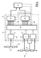
- Set 2 presented to the figure 1 includes a first circuit breaker 4A and a second circuit breaker 4B.
- the various elements included in the first circuit breaker 4A have their reference which ends with the letter A, while the various elements included in the second circuit breaker 4B have their reference which ends with the letter B.
- the first circuit breaker 4A corresponds to a first embodiment of the invention
- the second circuit breaker 4B corresponds to a second embodiment of the invention.
- first circuit breaker 4A and the second circuit breaker 4B will be presented successively using the Figures 1 to 3 and 5 , and respectively figures 1 , 4 and 5 .
- the first circuit breaker 4A is connected between, on the one hand, a first 6A and a second 8A electrical input conductors and, on the other hand, a first 10A and a second 12A electrical output conductors.
- the first circuit breaker 4A comprises contacts, not shown, movable between an open position and a closed position.
- the first circuit breaker 4A is adapted, when the movable contacts are in the closed position, to electrically connect the first electrical input conductor 6A with the first electrical output conductor 10A, and the second electrical input conductor 8A with the second electrical conductor 12A output.
- the first circuit breaker 4A is capable, when the movable contacts are in the open position, to electrically isolate the first electrical input conductor 6A from the first electrical output conductor 10A, and the second electrical input conductor 8A from the second electrical output conductor. 12A.
- the first circuit breaker 4A comprises an electronic tripping unit 14A and a calibration member 16A of the electronic tripping unit 14A.
- the first electrical input conductor 6A and the first electrical output conductor 10A are, for example, electrical phase conductors or positive positive potential.
- the second input electrical conductor 8A and the second electrical output conductor 12A are, for example, neutral conductors or even reference continuous potential conductors.
- the triggering unit 14A comprises a member 18A for measuring a current flowing through the first circuit breaker 4A, a member 22A for triggering the opening of the moving contacts of the first circuit breaker 4A, a processor 24A and a memory 26A associated with the processor 24A. .
- the calibration member 16A illustrated in more detail in FIG. figure 2 , comprises a first 28A and a second 30A storage members respectively first and second predetermined identifiers.
- the calibration member 16A also comprises a first 32A and a second 34A respectively reading members of the first, respectively second predetermined identifiers.
- the first and respectively second reading members 32A, 34A are associated with the first 28A and the second 30A storage members respectively.
- the first calibration member 16A is, for example, installed in the first circuit breaker 4A during the manufacture in the factory of the first circuit breaker 4A.
- the trigger member 22A is adapted to control the opening of the contacts of the first circuit breaker 4A.
- the trigger member 22A comprises, for example, a coil, not shown, adapted to control the opening of the contacts of the first circuit breaker 4A as a function of the current flowing therethrough.
- the processor 24A is adapted to execute software stored in the memory 26A.
- the memory 26A is capable of storing a software 35A for controlling the trigger member 22A and a control software 36A for the calibration member 16A.
- the control software 36A is clean, when it is executed by the processor 24A, to generate a reading command of the first and second predetermined identifiers and to transmit to each reading element 32A, 34A the generated read command.
- the memory 26A is also capable of storing a software 37A for determining calibration data according to the first and second predetermined identifiers.
- the calibration data define at least one control condition of the opening of the contacts of the circuit breaker 4A by the trigger member 22A.
- the calibration data correspond, for example, to a rated current of the first circuit breaker 4A determined according to the first identifier, and to a breaking capacity of the first circuit breaker 4A determined according to the second identifier.
- the rated current is the current that the circuit breaker 4A is capable of withstanding under specified conditions of continuous duty testing while respecting heating limits.
- the breaking capacity corresponds to a maximum intensity of a current that the first circuit breaker 4A is able to interrupt without deteriorating.
- the memory 26A is, in addition, able to store a predetermined datum D corresponding to a configuration of the first circuit breaker 4A.
- the data D is, for example, able to take a first or a second predetermined value each corresponding to a respective configuration of the first circuit breaker 4A.
- the first value corresponds to a digital configuration, corresponding to the fact that each predetermined identifier is stored by the storage devices 28A, 30A in a digital format.
- the second predetermined value corresponds to an analog configuration, corresponding to the fact that each predetermined identifier is stored by storage devices 28B, 30B in an analog format.
- the first storage device 28A is adapted to store the first predetermined identifier, according to which the triggering unit 14A is suitable for open the contacts of the 4A circuit breaker.
- the first storage member 28A is electrically connected to inputs 38A of the first reading member 32A.
- the second storage member 30A is adapted to store the second predetermined identifier, according to which the triggering unit 14A is able to control the opening of the contacts of the circuit breaker 4A.
- the second memory device 30A is electrically connected to inputs 40A of the second reading member 34A.
- the first 28A and second 30A storage members comprise resistors RA each connected on the one hand, either to an electronic ground M, or to a predetermined potential VA different from the mass and, on the other hand, to one of the inputs 38A, 40A of the first 32A, respectively second 34A, reading organs.
- Each resistor RA is connected to an input other than the first 32A or second reader 34A.
- the resistor RA connected to said input is connected, for example by an operator, at the predetermined potential VA.
- the resistor RA connected to said input is connected to the ground M.
- each storage member 28A, 30A comprises eight resistors RA, three of which are connected to the ground M and five to the predetermined potential VA, for encoding and storing the first and second predetermined identifiers, each on 8 bits.
- Each stored predetermined identifier comprises, at the input of the reading device 32A, corresponding 34A, at least one bit of data and at least one verification bit, and more specifically in the example of the figure 2 , five data bits and three verification bits, such as cyclic redundancy check bits.
- each predetermined identifier comprises a first number of verification bits greater than or equal to 2, preferably equal to 3.
- the first 32A and second 34A reading members comprise shift registers.
- These reading members 32A, 34A are preferably shift registers, such as parallel-series shift registers, each comprising eight inputs 38A, 40A in parallel and a single output 41A, 42A connected in series to the unit. trigger 14A.
- the readers 32A, 34A are adapted to, in response to the transmission of the read command, read the first and second predetermined identifiers and send them to the triggering unit 14A.
- the read command corresponds to a read command of the first and second identifiers.
- Each shift register comprises a set of synchronous flip-flops, not shown, also called logic circuits, controlled via the read command.
- An output of each flip-flop is for example connected to the input of the next flip-flop.
- a data item introduced in a first flip-flop propagates according to a clock signal, as a function of the read command, in one or more following flip-flops.
- the first reader 32A is adapted to store the first identifier temporarily only when it is electrically powered.
- the second reading member 34A is adapted to memorize the second identifier temporarily only when it is electrically powered.
- the reading members 32A, 34A are adapted to simultaneously receive the read command.
- the reading members 32A, 34A are adapted to, in response to the transmission of the read command, read the first predetermined identifier, respectively the second predetermined identifier, and send to the triggering unit 14A the first, respectively second predetermined identifiers read .
- the reading members 32A, 34A, and consequently the calibration member 16A are adapted, in response to the transmission of the read command of each predetermined identifier, to read each predetermined identifier stored in each storage member 28A, 30A. and send to the triggering unit 14A, via the outputs 41A, 42A, each predetermined identifier read, in a time less than 300 ⁇ s, preferably less than 200 ⁇ s.
- the control software 35A of the tripping member is adapted, when it is executed by the processor 24A, to control the opening of the contacts of the circuit breaker, as a function of the calibration data or data and the measured current value. by the measuring member 18A.
- the control software 35A is, for example, able to define the current flowing through a coil of the tripping member 22A to control the opening of the contacts of the circuit breaker 4A when the value of the measured current is greater than one of the data of FIG. calibration.
- the control software 36A of the calibration member 16A is adapted for, when executed by the processor 24A, to generate the read command, and then to transmit the generated read command to each read member 32A, 34A.
- the order of reading is preferably a predetermined command stored in the memory 26A.
- the control software 36A is adapted to be executed by the processor 24A, and to generate the read command, and then transmit the generated read command, only when the current measured by the current measuring device 18A is greater than a value predetermined current threshold.
- the control software 36A is, for example, able to generate the read command following waiting for a predetermined delay, of the order of 10 ⁇ s, after the measuring device 18A has measured a current of a intensity greater than the current threshold value or more generally after the electronic trigger unit 14A has been powered by any power source allowing its operation.
- the current threshold value corresponds to a minimum current value allowing the supply and operation of the triggering unit 14A and the calibration member 16A.
- the current threshold value is for example equal to 10% of a value of a minimum current triggering the opening of the contacts of the first circuit breaker 4A.
- a first signal S1 internal to the tripping unit 14A goes from a low logic state to a high logic state when the value of the intensity of the measured current is greater than the current threshold value or more generally when the Trigger unit 14A is properly powered to operate. This makes it possible to indicate to the triggering unit, and in particular to the processor 26A, that the supply of the triggering unit 14A is sufficient for the generation of the read command.
- control software 36A is adapted to read the predetermined datum D, and modify the read command if the predetermined datum does not correspond to the digital configuration, that is to say to the first predetermined value.
- the data D corresponds to the digital configuration and the read command remains unchanged.
- the control software 36A is also adapted to verify, as a function of the verification bit or bits, the validity of the data bit or bits read and sent by each reading element 32A, 34A to the triggering unit 14A.
- the control software 36A is able to generate the read command which, as shown in FIG. figure 3 , comprises a second signal S2 and a third signal S3.
- the second signal S2 is able to cause loading, in the first 32A, respectively second 34A, reading elements, the first, respectively second, predetermined identifiers, and their eight bits present on the inputs 38A, 40A, when they go from a high logic state to a low logic state during a given period, of the order for example 10 ⁇ s.
- the control software 36A is able to generate the second signal S2 and to make the second signal S2 from the high logic state to the low logic state, when the first internal signal S1 passes, for example, from a state logic down to a logic high.
- each reading element is able to send to the tripping unit, via the corresponding output 41A, 42A, a most significant bit of the first and second identifiers respectively. predetermined.
- the control software 36A is able to generate the third signal S3 with a succession of 7 cycles of duration, for example, equal.
- the seven cycles are comparable to a clock signal and have a period for example equal to 20 ⁇ s.
- the seven cycles allow the first, respectively second, reading members 32A, 34A to transmit successively, on their corresponding output 41A, 42A, the 7 bits of the first and second predetermined identifiers following the most significant bit.
- the third signal S3 is capable of timing the transmission of each bit of the predetermined identifiers on the outputs 41A, 42A of each reading member 32A, 34A.
- Each serial output 41A, 42A is thus able to successively transmit the 8 bits of the predetermined identifier read to the triggering unit 14A.
- the determination software 37A is clean, when executed by the processor 24A, to associate with each predetermined identifier the corresponding calibration data.
- a fourth signal S4 represents the state of the output 41A of the first reading member 32A during the transmission of the read command to the first reading member 32A. It is observed that each bit of the first predetermined identifier is successively transmitted to the triggering unit 14A.
- the second circuit breaker 4B is connected between, on the one hand, a first 6B and a second 8B electrical input conductors and, on the other hand, a first 10B and a second 12B electrical output conductors.
- the second circuit breaker 4B comprises contacts, not shown, movable between an open position and a closed position.
- the second circuit breaker 4B comprises an electronic triggering unit 14B, a calibration member 16B of the electronic triggering unit 14B and a first 28B, and a second 30B respectively, members for storing a first and a second one, predetermined identifiers.
- the triggering unit 14B comprises a member 18B for measuring the current flowing through the second circuit breaker 4B, a member 22B for triggering the opening of the contacts, a processor 24B and a memory 26B associated with the processor 24B.
- the calibration member 16B illustrated in detail in FIG. figure 4 , comprises a first 32B, and respectively a second 34B, reading members of the first, and respectively second, predetermined identifiers.
- the calibration member 16B also comprises an adaptation member 31 B receiving as input, for each first storage member, the predetermined identifier, and connected at the output to the inputs 38B, 40B of the first 32B and second 34B reading members .
- the processor 24B is adapted to execute software stored by the memory 26B.
- the memory 26B is similar to the memory 26A described above, and is capable of storing a software 35B for controlling the triggering member, a software 36B for controlling the calibration member 16B and a software 37B for determining the one or more calibration data.
- the memory 26B is also able to store the predetermined datum D corresponding to the configuration of the second circuit breaker 4B.
- the control software 36B is clean, when executed by the processor 24B, to generate a read command and to transmit to each reading member 32B, 34B the read command generated.
- the first storage device 28B is adapted to store a first predetermined identifier, according to which the triggering unit 14B is able to control the opening of the contacts of the circuit breaker 4B.
- the second storage member 30B is adapted to store a second predetermined identifier, according to which the triggering unit 14B is adapted to control the opening of the contacts of the circuit breaker 4B.
- the first 28B and second 30B storage members are electrically connected to inputs E of the adaptation member 31B.
- the first 28B and second 30B storage members are, for example, installed in the circuit breaker during its manufacture in the factory.
- the first 28B and second 30B storage members comprise RB resistors of adjustable values, supplied with voltage via the predetermined potential VA when the contacts of the circuit breaker 4B are closed or when the electronic triggering unit 14B is powered by a power supply whatever, and adapted to vary an electrical quantity transmitted to the adaptation member 31 B.
- the resistors RB of each storage member 28B, 30B are connected to each other between the electrical ground M and the predetermined potential.
- the predetermined identifiers are thus stored by the first 28B and second 30B storage members in the form of an electrical quantity, such as a voltage, that is to say in an analog format.
- the first storage member 28B comprises two adjustable resistors RB, while the second storage member 30B comprises three adjustable resistors RB.
- the adaptation member 31B receives on its inputs, for each first 28B, respectively second 30B, storage device, the electrical quantity corresponding to the first and second predetermined identifiers respectively.
- the adaptation member 31 B is adapted to provide the first 32B and second 34B reading members on their respective inputs 38B, 40B, the first and second respectively, predetermined identifiers in a predetermined digital format.
- the adaptation member 31 B is suitable, for each storage member 28B, 30B, to supply to one of the reading members 32B, 34B, on the inputs of the reading member 32B, 34B, the identifier predetermined which has a second number of verification bits less than or equal to the first number of verification bits of each predetermined identifier in the first circuit breaker 4A, that is to say in the calibration member 16A.
- the second number of check bits is preferably 1.
- Each predetermined identifier comprises, according to its predetermined digital format, at the input of the reading member 32B, corresponding 34B, at least one bit of data and at least one verification bit, and more specifically in the example of the figure 5 , five bits of data and a check bit, such as a parity bit.
- the adaptation member 31 B is adapted to, in response to the transmission of the read command, convert in the predetermined digital format the first and second predetermined identifiers.
- the adaptation member 31 B comprises analog-digital converters 45B adapted to convert the electrical quantities into digital quantities.
- the adaptation member 31 B also comprises a conversion element 46B, such as a programmable logic circuit, connected to the outputs 44B of the converters 45B, and adapted to transmit to the reading members 32B, 34B, the predetermined identifiers in the predetermined digital format, following the transmission of the read command to the calibration member 16B.
- the reading members 32B, 34B are adapted to, in response to the transmission of the read command, read the first and second predetermined identifiers and send to the triggering unit 14B the first and second identifiers. predetermined read.
- the reading members 32B, 34B are adapted to simultaneously receive the read command.
- the reading members 32B, 34B are adapted to, in response to the transmission of the read command, simultaneously read the first predetermined identifier, respectively the second predetermined identifier, transmitted by the adaptation member 31B and send to the trigger unit 14B, the first, respectively second, identifiers.
- the calibration member 16B is adapted, in response to the transmission of the read command of each predetermined identifier, to read each predetermined identifier and to send to the triggering unit 14B each identifier in a delay of less than 300 ⁇ s, preferably less than 200 ⁇ s.
- control software 36B is adapted to be executed by the processor 24B, and to generate the read command and then transmit the generated read command, when the current measured by the measuring device of the current 18B is greater than a predetermined current threshold value or, more generally, when the triggering unit 14B is electrically powered.
- the read command generated and transmitted then corresponds to that presented in the first embodiment.
- the control software 36B is able to read the predetermined datum D.
- the predetermined datum D corresponds to the analog configuration, which is the case for the second circuit breaker 4B
- the control software 36B is able to modify the read command transmitted to the calibration member 16B.
- the read command is modified to restart the reading of each predetermined identifier.
- the triggering unit 14B is adapted to transmit the read command and to recover information transmitted by the reading members, whereas the analog-digital converters 45B do not necessarily transmit stable digital quantities to the conversion member. 46B.
- the predetermined time is for example equal to 40 ⁇ s.
- the read command is modified to control reading of the five data bits and the check bit.
- the transmission time of the predetermined identifiers to the triggering unit 14B, following the generation of the read command, is the same in the first and in the second embodiment. Indeed, the fact that in the second embodiment, the number of bits to be read at the input of the reading members is smaller than the first embodiment, makes it possible to reduce the number of bits to be read in the second embodiment. and therefore taking into account the predetermined time.
- circuit breakers 4A and 4B will now be presented using the figure 5 having a method of calibrating the tripping unit 14A, 14B of the first 4A and the second 4B circuit breakers.
- the memory 26A, 26B stores the predetermined data D.
- the predetermined datum is, for example, provided by the operator to the memory 26A, 26B via a data entry operation D.
- the control software generates the read command and transmits the generated read command to the calibrator 16A, 16B.
- the read command is, for example, generated when the measuring device 18A, 18B measures a current whose intensity is greater than the predetermined threshold value or, more generally, when the triggering unit 14A , 14B is powered by any power source.
- the read command is then transmitted to the calibration member 16A, 16B.
- a first reading step 104 the calibration member 16A, 16B and, more precisely, the reading members 32A, 32B, 34A, 34B read the predetermined identifiers and send the first and second identifiers read to the first reader.
- trigger unit 14A, 14B according to the read command and in response to the read command.
- the triggering unit 14A, 14B then receives the bits forming the predetermined identifiers.
- the first reading step 104 and the generating step 102 take place in parallel for a predetermined duration of less than 300 ⁇ s, preferably of 200 ⁇ s.
- control software 36A, 36B performs a recovery step 106, during which it retrieves the predetermined data item D in the memory 26A, 26B and identifies the data item. predetermined D recovered. Following the recovery step 106, the control software knows the type of configuration of the circuit breaker 4A, 4B.
- the read command remains unchanged and corresponds to a predetermined read command, for example stored in the memory 26A.
- the generation 102 and read 104 steps are then executed until all the bits of the first and second identifiers have been transmitted to the triggering unit 14A, 14B.
- the control software 36B performs a modification step 108, during which the read command is modified as than previously presented. Parameters making it possible to carry out this modification are, for example, stored in the memory 26B.
- the control software 36A, 36B transmits to the calibration member 14A, 14B the modified read command.
- the reading members 32A, 32B, 34A, 34B read the first and second identifiers and send the first and second predetermined identifiers read to the triggering unit 14A, 14B, according to of the modified read command and in response to the modified read command.
- a verification step 114 is performed.
- the control software verifies, for each predetermined identifier, the validity of the data bits read and transmitted by the reading elements, as a function of the verification bit or bits read and transmitted by the organs. 32A, 34A, 32B, 34B.
- control software 36A, 36B detects that the data bits sent by one of the reading members 32A, 34A, 32B, 34B are not valid or are erroneous, then the control software 36A, 36B sets the value of the five data bits of the predetermined identifier concerned equal to a fault value and transmits the data bits to the determination software 37A, 37B.
- control software 36A, 36B detects that the data bits transmitted by the reading members 32A, 34A, 32B, 34B are valid, then the control software 36A, 36B transmits to the determination software 37A, 37B the five data bits of the first and second identifiers.
- the determination software 37A, 37B associates, with the five data bits corresponding to the first identifier, a first calibration data item, and with the five corresponding data bits, with the second identifier a second data item. calibration.
- control software 35A, 35B and the trigger member 22A, 22B then controls, during a control step 118, the opening of the circuit breaker according to the calibration data and the current measured by the measuring member. 18A, 18B.
- the calibration members 16A, 16B enable the predetermined identifiers to be transmitted reliably and quickly to the triggering unit 14A, 14B.
- the triggering unit is thus able to determine the calibration data according to the predetermined identifiers reliably and quickly.
- the safety of an electrical installation including circuit breakers 4A, 4B provided with such calibration members is thus improved, in particular when closing the mobile contacts of the circuit breaker on a short circuit.
- controlling the data bits received by the tripping unit based on one or more verification bits improves the reliability of a circuit breaker comprising such calibration members 16A, 16B.
- the calibration members 16A, 16B have, when they are controlled by the triggering unit 14A, 14B, a response time to the identical read command.
- the calibration member 16B of the second circuit breaker 4B is intended to be installed on existing circuit breakers, comprising storage members of the predetermined identifiers in an analog format and in which the reliability and the speed of the transmission of the predetermined identifiers are thus improved.
- the calibration member 16A is intended to be installed in a circuit breaker such as the first circuit breaker 4A. It makes it possible to improve the reliability and the speed of the transmission of the predetermined identifiers to the triggering unit 14A.
- the reading members 32A, 34A, 32B, 34B are series-series or series-parallel or parallel-parallel shift registers.
- Each predetermined identifier is a parameter associated with one of the circuit breakers 4A, 4B, for example a parameter relating to a value of tripping of the opening of the contacts of the circuit breaker 4A, 4B.
Abstract
Cet organe de calibrage (16A) d'une unité électronique (14A) de déclenchement d'un disjoncteur, qui comprend un organe de déclenchement de l'ouverture de contacts du disjoncteur et des moyens de pilotage de l'organe de déclenchement, comprend au moins un organe de lecture (32A, 34A) adapté pour lire le contenu d'au moins un premier organe de mémorisation (28A, 30A). Chaque premier organe de mémorisation (28A, 30A) est adapté pour mémoriser un identifiant prédéterminé. L'unité de déclenchement électronique comprend également des moyens de contrôle, adaptés pour générer et transmettre à chaque organe de calibrage une commande de lecture de chaque identifiant prédéterminé et l'unité de déclenchement (14A) est adaptée pour commander l'ouverture des contacts du disjoncteur en fonction de chaque identifiant prédéterminé. Chaque organe de lecture (32A, 34A) comporte un registre à décalage adapté pour, en réponse à la transmission de la commande de lecture, lire chaque identifiant prédéterminé et envoyer à l'unité de déclenchement (14A) chaque identifiant prédéterminé lu.This calibration member (16A) of an electronic unit (14A) for tripping a circuit breaker, which comprises a tripping member for opening the circuit-breaker contacts and means for controlling the tripping member, comprises at least one reading member (32A, 34A) adapted to read the contents of at least one first memory member (28A, 30A). Each first storage device (28A, 30A) is adapted to store a predetermined identifier. The electronic trip unit also comprises control means adapted to generate and transmit to each calibration member a read command of each predetermined identifier and the trigger unit (14A) is adapted to control the opening of the contacts of the circuit breaker according to each predetermined identifier. Each readout member (32A, 34A) includes a shift register adapted to, in response to the transmission of the read command, read each predetermined identifier and send to the trigger unit (14A) each predetermined identifier read.
Description
La présente invention concerne un organe de calibrage d'une unité électronique de déclenchement d'un disjoncteur, un ensemble de tels organes de calibrage, un disjoncteur comprenant un tel organe de calibrage, et un procédé de calibrage de l'unité de déclenchement d'un tel disjoncteur.The present invention relates to a calibration member of an electronic circuit breaker tripping unit, a set of such calibration members, a circuit breaker comprising such a calibration member, and a method of calibrating the tripping unit of a circuit breaker. such a circuit breaker.
L'unité de déclenchement comprend un organe de déclenchement de l'ouverture de contacts du disjoncteur et des moyens de pilotage de l'organe de déclenchement.The tripping unit comprises a tripping member for opening contacts of the circuit breaker and means for controlling the tripping member.
L'invention s'applique plus spécifiquement aux disjoncteurs électroniques qui sont propres à être utilisés avec différents types d'unités électroniques de déclenchement. Ces unités de déclenchement sont généralement amovibles, et sont montées dans le disjoncteur par exemple lors de l'installation du disjoncteur sur une installation électrique. Dans de tels disjoncteurs, l'unité de déclenchement mesure le courant circulant à travers le disjoncteur dans lequel elle est installée. Elle commande l'ouverture des contacts du disjoncteur en fonction du courant mesuré, des valeurs de calibre propres à un châssis du disjoncteur et au fonctionnement mécanique du disjoncteur et d'autres réglages. De telles valeurs de calibre sont généralement inconnues de l'unité de déclenchement lors de son installation dans le disjoncteur, car l'objectif est d'avoir des unités de déclenchement interchangeables et non spécifiques à un certain type de disjoncteur électronique.The invention more specifically applies to electronic circuit breakers which are suitable for use with different types of electronic trip units. These trip units are generally removable, and are mounted in the circuit breaker for example when installing the circuit breaker on an electrical installation. In such circuit breakers, the trip unit measures the current flowing through the circuit breaker in which it is installed. It controls the opening of the circuit breaker contacts according to the measured current, the specific ratings of a circuit breaker frame and the mechanical operation of the circuit breaker and other settings. Such gauge values are generally unknown to the trip unit when installed in the circuit breaker, as the goal is to have interchangeable and unspecific trip units for some type of electronic circuit breaker.
Afin de régler les valeurs de calibre et de les transmettre à l'unité de déclenchement, il est ainsi connu d'installer dans de tels disjoncteurs des organes de calibrage adaptés pour mémoriser les valeurs de calibre et les transmettre à l'unité de déclenchement lors de la mise sous tension du disjoncteur, c'est-à-dire lorsque ses contacts sont fermés et qu'il est installé sur l'installation électrique ou plus généralement alimenté par une source d'alimentation quelconque. Les organes de calibrage sont généralement montés en usine sur le disjoncteur et ne sont pas réglables par un utilisateur. En effet, ils dépendent du châssis du disjoncteur et des performances mécaniques du disjoncteur.In order to adjust the size values and to transmit them to the tripping unit, it is thus known to install in such circuit breakers calibrating members adapted to memorize the size values and transmit them to the tripping unit when switching on the circuit breaker, that is to say when its contacts are closed and it is installed on the electrical installation or more generally powered by any power source. Calibration devices are usually factory mounted on the circuit breaker and are not adjustable by a user. Indeed, they depend on the chassis of the circuit breaker and the mechanical performance of the circuit breaker.
Il est connu, en outre, d'utiliser des organes de calibrage qui comprennent des circuits analogiques permettant de fixer les valeurs de calibre sous la forme de grandeurs électriques, telles que des tensions. Les grandeurs électriques sont ensuite exploitées par un convertisseur analogique-numérique, puis écrites dans une mémoire de l'unité de déclenchement.It is known, moreover, to use calibration members which comprise analog circuits making it possible to fix the size values in the form of electrical quantities, such as voltages. The electrical quantities are then exploited by an analog-digital converter and then written in a memory of the tripping unit.
Cependant, l'utilisation d'une mémoire rend assez long le temps d'accès aux valeurs de calibre. De plus, les circuits analogiques sont sensibles aux perturbations électromagnétiques, et une telle solution est donc complexe et peu fiable particulièrement en environnement perturbé.However, the use of a memory makes the access time to the caliber values rather long. In addition, the analog circuits are sensitive to electromagnetic disturbances, and such a solution is therefore complex and unreliable, particularly in a disturbed environment.
Il est également connu du document
Le but de l'invention est donc de proposer un organe de calibrage fiable et rapide permettant de fournir au disjoncteur, et plus spécifiquement à son unité de déclenchement, les valeurs de calibre avec une fiabilité et une vitesse améliorées.The object of the invention is therefore to provide a reliable and fast calibration member for providing the circuit breaker, and more specifically to its tripping unit, the size values with improved reliability and speed.
A cet effet, l'invention a pour objet un organe de calibrage d'une unité électronique de déclenchement d'un disjoncteur, l'unité de déclenchement comprenant un organe de déclenchement de l'ouverture de contacts du disjoncteur et des moyens de pilotage de l'organe de déclenchement, l'organe de calibrage comprenant au moins un organe de lecture adapté pour lire le contenu d'au moins un premier organe de mémorisation, chaque premier organe de mémorisation étant adapté pour mémoriser un identifiant prédéterminé, l'unité de déclenchement électronique comprenant également des moyens de contrôle de l'organe de calibrage, adaptés pour générer et transmettre à chaque organe de calibrage une commande de lecture de chaque identifiant prédéterminé, l'unité de déclenchement étant adaptée pour commander l'ouverture des contacts du disjoncteur en fonction de chaque identifiant prédéterminé. Conformément à l'invention, chaque organe de lecture comporte un registre à décalage adapté pour, en réponse à la transmission de la commande de lecture, lire chaque identifiant prédéterminé et envoyer à l'unité de déclenchement chaque identifiant prédéterminé lu.For this purpose, the object of the invention is a device for calibrating an electronic unit for tripping a circuit-breaker, the tripping unit comprising a device for tripping the opening of contacts of the circuit-breaker and means for controlling the circuit breaker. the triggering member, the calibrating member comprising at least one reading member adapted to read the contents of at least one first memory member, each first memory member being adapted to memorize a predetermined identifier, the unit of electronic trigger also comprising means for controlling the calibration member, adapted to generate and transmit to each calibration member a read command of each predetermined identifier, the trigger unit being adapted to control the opening of the contacts of the circuit breaker according to each predetermined identifier. According to the invention, each reading element comprises a shift register adapted to, in response to the transmission of the read command, read each predetermined identifier and send to the trigger unit each predetermined identifier read.
Grâce à l'invention, le temps de récupération de chaque identifiant prédéterminé par l'unité de déclenchement est amélioré, et le temps nécessaire pour l'ouverture des contacts du disjoncteur lorsque les contacts sont fermés sur un court-circuit est alors réduit. En effet, chaque registre à décalage permet une transmission fiable et rapide de chaque identifiant prédéterminé à l'unité de déclenchement, qui est apte à commander l'ouverture des contacts du disjoncteur en fonction de chaque identifiant prédéterminé, et ce dès réception desdits identifiants.Thanks to the invention, the recovery time of each identifier predetermined by the tripping unit is improved, and the time required for the opening of the contacts of the circuit breaker when the contacts are closed on a short circuit is then reduced. Indeed, each shift register allows a reliable and fast transmission of each identifier predetermined to the tripping unit, which is able to control the opening of the contacts of the circuit breaker according to each predetermined identifier, and upon receipt of said identifiers.
Selon différents aspects de l'invention, l'organe de calibrage comprend une ou plusieurs des caractéristiques suivantes, prises isolément ou suivant toutes les combinaisons techniquement admissibles :
- chaque registre à décalage comprend un ensemble de bascules synchrones, commandées via la commande de lecture ;
- chaque organe de lecture est connecté à un premier organe de mémorisation correspondant, et est adapté pour mémoriser l'identifiant de manière temporaire seulement lorsqu'il est alimenté électriquement ;
- l'organe de calibrage est adapté pour, en réponse à la transmission de la commande de lecture de chaque identifiant prédéterminé, lire chaque identifiant prédéterminé mémorisé dans chaque premier organe de mémorisation et envoyer à l'unité de déclenchement chaque identifiant lu, dans un délai inférieur à 300 µs, de préférence inférieur à 200 µs ;
- chaque organe de lecture comprend une ou plusieurs entrées propres à recevoir chacune au moins l'un des identifiants prédéterminés, chaque identifiant prédéterminé comprenant au moins un bit de donnée et au moins un bit de vérification, les moyens de contrôle étant adaptés pour vérifier en fonction du ou des bits de vérification la validité du ou des bits de donnée lus et envoyés par chaque organe de lecture ;
- chaque organe de lecture comporte un registre à décalage parallèle-série comprenant plusieurs entrées en parallèle et une unique sortie, et dans lequel l'organe de calibrage comprend chaque premier organe de mémorisation, et chaque premier organe de mémorisation comprend des résistances connectées chacune d'une part, soit à une masse électronique, soit à un potentiel prédéterminé différent de la masse et, d'autre part, à l'une des entrées en parallèle de l'un des registres à décalage ;
- le disjoncteur comprend chaque premier organe de mémorisation, chaque premier organe de mémorisation comprenant au moins une résistance de valeur réglable, l'identifiant prédéterminé correspondant à une grandeur électrique associée à la ou aux résistances réglables, l'organe de calibrage comprenant un organe d'adaptation recevant en entrée, pour chaque premier organe de mémorisation, la grandeur électrique correspondante et étant adapté pour fournir à l'un des organes de lecture l'identifiant prédéterminé ;
- l'organe de calibrage comprend plusieurs organes de lecture chacun associé à un premier organe de mémorisation différent.
- each shift register comprises a set of synchronous flip-flops, controlled via the read command;
- each reading member is connected to a corresponding first memory member, and is adapted to memorize the identifier temporarily only when it is electrically powered;
- the calibrating member is adapted, in response to the transmission of the read command of each predetermined identifier, to read each predetermined identifier stored in each first storage device and to send each read identifier to the triggering unit within a set period of time. less than 300 μs, preferably less than 200 μs;
- each reading element comprises one or more inputs adapted to each receive at least one of the predetermined identifiers, each predetermined identifier comprising at least one bit of data and at least one verification bit, the control means being adapted to check in function the verification bit or bits the validity of the data bit or bits read and sent by each reading element;
- each reading element comprises a parallel-series shift register comprising a plurality of parallel inputs and a single output, and wherein the calibration element comprises each first storage device, and each first storage device comprises resistors each connected to each other; either to an electronic ground or to a predetermined potential different from the ground and, secondly, to one of the parallel inputs of one of the shift registers;
- the circuit breaker comprises each first storage device, each first storage device comprising at least one adjustable value resistor, the predetermined identifier corresponding to an electrical quantity associated with the adjustable resistor (s), the calibration device comprising a device adaptation receiving as input, for each first storage member, the corresponding electrical quantity and being adapted to supply to one of the reading members the predetermined identifier;
- the calibration member comprises a plurality of reading members each associated with a different first memory member.
L'invention a également pour objet un ensemble d'au moins deux organes de calibrage, comprenant au moins un premier organe de calibrage tel que présenté ci-dessus, dans lequel chaque premier organe de mémorisation est adapté pour mémoriser l'identifiant prédéterminé qui comporte un premier nombre prédéterminé de bits de vérification supérieur ou égal à 2, de préférence égal à 3, et un deuxième organe de calibrage tel que présenté ci-dessus, dans lequel l'organe d'adaptation est propre, pour chaque premier organe de mémorisation, à fournir à l'un des organes de lecture, l'identifiant prédéterminé comportant un deuxième nombre de bits de vérification inférieur ou égal au premier nombre de bits de vérification de chaque identifiant prédéterminé dans le premier organe de calibrage, le deuxième nombre de bits de vérification étant de préférence égal à 1.The subject of the invention is also an assembly of at least two calibration members, comprising at least a first calibration member as presented above, in which each first storage member is adapted to memorize the predetermined identifier which comprises a first predetermined number of verification bits greater than or equal to 2, preferably equal to 3, and a second calibration element as presented above, in which the adaptation member is clean, for each first memory element to supply to one of the reading elements, the predetermined identifier comprising a second number of verification bits less than or equal to the first number of verification bits of each predetermined identifier in the first calibration element, the second number of bits check is preferably 1.
L'invention a également pour objet un disjoncteur, comprenant un organe de calibrage et une unité électronique de déclenchement, l'unité de déclenchement comprenant un organe de déclenchement de l'ouverture de contacts du disjoncteur, des moyens de pilotage de l'organe de déclenchement et des moyens de contrôle de l'organe de calibrage. Conformément à l'invention, l'organe de calibrage est tel que présenté ci-dessus.The invention also relates to a circuit breaker, comprising a calibration member and an electronic triggering unit, the triggering unit comprising a triggering member for opening contacts of the circuit breaker, means for controlling the actuator member. tripping and control means of the calibration member. According to the invention, the calibration member is as shown above.
Avantageusement, l'unité de déclenchement électronique comprend des moyens de détermination propres à associer à chaque identifiant prédéterminé, envoyé par chaque organe de lecture, une donnée de calibrage, la ou les données de calibrage définissant au moins une condition de commande de l'ouverture des contacts du disjoncteur et les moyens de pilotage étant adaptés pour commander l'ouverture des contacts en fonction de la ou des données de calibrage.Advantageously, the electronic triggering unit comprises determining means adapted to associate with each predetermined identifier, sent by each reading element, a calibration data item, the calibration data or data defining at least one control condition of the opening. contacts of the circuit breaker and the control means being adapted to control the opening of the contacts according to the calibration data or data.
L'invention concerne, en outre, un procédé de calibrage d'une unité de déclenchement d'un disjoncteur par un organe de calibrage, l'unité de déclenchement comprenant un organe de déclenchement de l'ouverture de contacts du disjoncteur et des moyens de pilotage de l'organe de déclenchement, l'organe de calibrage comprenant au moins un organe de lecture, adapté pour lire le contenu d'au moins un premier organe de mémorisation, chaque premier organe de mémorisation étant adapté pour mémoriser un identifiant prédéterminé, le procédé comprenant les étapes suivantes : la génération d'une commande de lecture de chaque identifiant prédéterminé, la transmission de la commande de lecture à l'organe de calibrage, la commande de l'ouverture des contacts du disjoncteur en fonction de chaque identifiant prédéterminé. Conformément à l'invention, l'organe de lecture comporte un registre à décalage et précédemment à l'étape de commande, le procédé comprend les étapes suivantes : la lecture, par le ou les organes de lecture, de chaque identifiant prédéterminé et l'envoi, à l'unité de déclenchement, de chaque identifiant prédéterminé lu lors de l'étape de lecture.The invention furthermore relates to a method of calibrating a tripping unit of a circuit breaker by a calibration device, the tripping unit comprising a device for tripping the opening of contacts of the circuit breaker and means for controlling the triggering member, the calibrating member comprising at least one reading member adapted to read the contents of at least one first memory member, each first memory member being adapted to memorize a predetermined identifier, the method comprising the steps of: generating a read command of each predetermined identifier, transmitting the read command to the calibration member, controlling the opening of the contacts of the circuit breaker according to each predetermined identifier. According to the invention, the reading element comprises a shift register and previously in the control step, the method comprises the following steps: reading, by the one or more reading members, each predetermined identifier and sending, to the trigger unit, each predetermined identifier read during the reading step.
Avantageusement, les étapes de lecture et de transmission ont lieu parallèlement pendant une durée prédéterminée et précédemment à l'étape de génération, le procédé comprend l'étape suivante : la mémorisation dans l'unité de déclenchement d'une donnée prédéterminée correspondant à une configuration du disjoncteur, et lors de l'étape de lecture, le procédé comprend les étapes suivantes : la récupération de la donnée prédéterminée, la modification de la commande de lecture en fonction de la donnée prédéterminée, la commande de lecture étant modifiée pour recommencer la lecture de chaque identifiant prédéterminé lorsque la donnée prédéterminée est égale à une valeur prédéterminée.Advantageously, the reading and transmission steps take place in parallel for a predetermined duration and before the generation step, the method comprises the following step: storing in the tripping unit a predetermined datum corresponding to a configuration of the circuit breaker, and during the reading step, the method comprises the following steps: the recovery of the predetermined data, the modification of the read command as a function of the predetermined data, the reading command being modified to restart the reading of each predetermined identifier when the predetermined datum is equal to a predetermined value.
L'invention sera mieux comprise et d'autres avantages de celle-ci apparaitront à la lumière de la description qui va suivre, donnée uniquement à titre d'exemple non limitatif, et faite en se référant aux dessins annexés, sur lesquels :
- la
figure 1 est une représentation schématique d'un ensemble comprenant un premier disjoncteur conforme à un premier mode de réalisation de l'invention et un deuxième disjoncteur conforme à un deuxième mode de réalisation de l'invention ; - la
figure 2 est une représentation schématique d'une unité de déclenchement et d'un organe de calibrage du premier disjoncteur de lafigure 1 ; - la
figure 3 est un chronogramme représentant deux signaux de commande d'un organe de calibrage du premier disjoncteur de lafigure 1 , un signal interne d'une unité de déclenchement dudit premier disjoncteur, et un signal de sortie transmis par l'organe de calibrage à l'unité de déclenchement ; - la
figure 4 est une représentation schématique d'une unité de déclenchement, d'un organe de calibrage et d'organes de mémorisation du deuxième disjoncteur de lafigure 1 ; et - la
figure 5 est un organigramme d'un procédé de calibrage des unités de déclenchement des premier et deuxième disjoncteurs de lafigure 1 .
- the
figure 1 is a schematic representation of an assembly comprising a first circuit breaker according to a first embodiment of the invention and a second circuit breaker according to a second embodiment of the invention; - the
figure 2 is a schematic representation of a tripping unit and a calibration member of the first circuit breaker of thefigure 1 ; - the
figure 3 is a timing diagram representing two control signals of a calibration member of the first circuit breaker of thefigure 1 an internal signal of a tripping unit of said first circuit breaker, and an output signal transmitted by the calibrating member to the tripping unit; - the
figure 4 is a schematic representation of a tripping unit, a calibration member and storage members of the second circuit breaker of thefigure 1 ; and - the
figure 5 is a flowchart of a method for calibrating the tripping units of the first and second circuit breakers of thefigure 1 .
L'ensemble 2 présenté à la
Le premier disjoncteur 4A correspond à un premier mode de réalisation de l'invention, et le deuxième disjoncteur 4B correspond à un deuxième mode de réalisation de l'invention.The
Dans la suite de la description, le premier disjoncteur 4A et le deuxième disjoncteur 4B seront présentés successivement à l'aide des
Le premier disjoncteur 4A est connecté entre, d'une part, un premier 6A et un deuxième 8A conducteurs électriques d'entrée et, d'autre part, un premier 10A et un deuxième 12A conducteurs électriques de sortie.The
Le premier disjoncteur 4A comprend des contacts, non représentés, mobiles entre une position ouverte et une position fermée.The
Le premier disjoncteur 4A est apte, lorsque les contacts mobiles sont en position fermée, à relier électriquement le premier conducteur électrique d'entrée 6A avec le premier conducteur électrique de sortie 10A, et le deuxième conducteur électrique d'entrée 8A avec le deuxième conducteur électrique de sortie 12A.The
Le premier disjoncteur 4A est apte, lorsque les contacts mobiles sont en position ouverte, à isoler électriquement le premier conducteur électrique d'entrée 6A du premier conducteur électrique de sortie 10A, et le deuxième conducteur électrique d'entrée 8A du deuxième conducteur électrique de sortie 12A.The
Le premier disjoncteur 4A comprend une unité de déclenchement électronique 14A et un organe 16A de calibrage de l'unité de déclenchement électronique 14A.The
Le premier conducteur électrique d'entrée 6A et le premier conducteur électrique de sortie 10A sont, par exemple, des conducteurs électriques de phase ou encore de potentiel continu positif.The first
Le deuxième conducteur électrique d'entrée 8A et le deuxième conducteur électrique de sortie 12A sont, par exemple, des conducteur de neutre ou encore des conducteur de potentiel continu de référence.The second input
L'unité de déclenchement 14A comprend un organe 18A de mesure d'un courant traversant le premier disjoncteur 4A, un organe 22A de déclenchement de l'ouverture des contacts mobiles du premier disjoncteur 4A, un processeur 24A et une mémoire 26A associée au processeur 24A.The triggering
L'organe de calibrage 16A, illustré de manière plus détaillée à la
Le premier organe de calibrage 16A est, par exemple, installé dans le premier disjoncteur 4A lors de la fabrication en usine du premier disjoncteur 4A.The
L'organe de déclenchement 22A est propre à commander l'ouverture des contacts du premier disjoncteur 4A. L'organe de déclenchement 22A comprend, par exemple, une bobine, non représentée, adaptée pour commander l'ouverture des contacts du premier disjoncteur 4A en fonction du courant la traversant.The
Le processeur 24A est adapté pour exécuter des logiciels mémorisés dans la mémoire 26A.The
La mémoire 26A est propre à mémoriser un logiciel 35A de pilotage de l'organe de déclenchement 22A et un logiciel 36A de contrôle de l'organe de calibrage 16A.The
Le logiciel de contrôle 36A est propre, lorsqu'il est exécuté par le processeur 24A, à générer une commande de lecture des premier et deuxième identifiants prédéterminés et à transmettre à chaque organe de lecture 32A, 34A la commande de lecture générée.The
La mémoire 26A est également propre à mémoriser un logiciel 37A de détermination de données de calibrage en fonction du premier et du deuxième identifiant prédéterminés. Les données de calibrage définissent au moins une condition de commande de l'ouverture des contacts du disjoncteur 4A par l'organe de déclenchement 22A. Les données de calibrage correspondent, par exemple, à un courant nominal du premier disjoncteur 4A déterminé en fonction du premier identifiant, et à un pouvoir de coupure du premier disjoncteur 4A déterminé en fonction du deuxième identifiant.The
Le courant nominal est le courant que le disjoncteur 4A est capable de supporter dans des conditions spécifiées d'essais en service continu tout en respectant des limites d'échauffement.The rated current is the current that the
Le pouvoir de coupure correspond à une intensité maximale d'un courant que le premier disjoncteur 4A est apte à interrompre sans se détériorer.The breaking capacity corresponds to a maximum intensity of a current that the
La mémoire 26A est, en outre, apte à mémoriser une donnée prédéterminée D correspondant à une configuration du premier disjoncteur 4A. La donnée D est, par exemple, propre à prendre une première ou une deuxième valeur prédéterminée correspondant chacune à une configuration respective du premier disjoncteur 4A. La première valeur correspond à une configuration numérique, correspondant au fait que chaque identifiant prédéterminé est mémorisé par les organes de mémorisation 28A, 30A sous un format numérique. La deuxième valeur prédéterminée correspond à une configuration analogique, correspondant au fait que chaque identifiant prédéterminé est mémorisé par des organes de mémorisation 28B, 30B sous un format analogique.The
Le premier organe de mémorisation 28A est adapté pour mémoriser le premier identifiant prédéterminé, en fonction duquel l'unité de déclenchement 14A est propre à commander l'ouverture des contacts du disjoncteur 4A. Le premier organe de mémorisation 28A est électriquement connecté à des entrées 38A du premier organe de lecture 32A.The
Le deuxième organe de mémorisation 30A est adapté pour mémoriser le deuxième identifiant prédéterminé, en fonction duquel l'unité de déclenchement 14A est propre à commander l'ouverture des contacts du disjoncteur 4A. Le deuxième 30A organe de mémorisation est électriquement connecté à des entrées 40A du deuxième organe de lecture 34A.The
Les premier 28A et deuxième 30A organes de mémorisation comprennent des résistances RA connectées chacune d'une part, soit à une masse électronique M, soit à un potentiel prédéterminé VA différent de la masse et, d'autre part, à l'une des entrées 38A, 40A des premier 32A, respectivement deuxième 34A, organes de lecture. Chaque résistance RA est connectée à une entrée différente du premier 32A ou deuxième 34A organe de lecture.The first 28A and second 30A storage members comprise resistors RA each connected on the one hand, either to an electronic ground M, or to a predetermined potential VA different from the mass and, on the other hand, to one of the
Pour coder un « 1 » logique et transmettre le « 1 » logique sur l'une des entrées 38A, 40A du premier 32A ou deuxième 34A organe de lecture, la résistance RA connectée à ladite entrée, est reliée, par exemple par un opérateur, au potentiel prédéterminé VA.To code a logical "1" and transmit the logic "1" to one of the
Pour coder un « 0 » logique et transmettre le « 0 » logique sur l'une des entrées 38A, 40A du premier 32A ou deuxième 34A organe de lecture, la résistance RA connectée à ladite entrée, est reliée à la masse M.To code a logic "0" and to transmit the logic "0" on one of the
Dans l'exemple de la
Chaque identifiant prédéterminé mémorisé comprend, en entrée de l'organe de lecture 32A, 34A correspondant, au moins un bit de donnée et au moins un bit de vérification, et plus spécifiquement dans l'exemple de la
Les premier 32A et deuxième 34A organes de lecture comportent des registres à décalage. Ces organes de lecture 32A, 34A sont de préférence des registres à décalage, tels que des registres à décalage parallèle-série, comprenant chacun huit entrées 38A, 40A en parallèle et une unique sortie 41 A, 42A connectée en série à l'unité de déclenchement 14A.The first 32A and second 34A reading members comprise shift registers. These
Les organes de lecture 32A, 34A sont adaptés pour, en réponse à la transmission de la commande de lecture, lire le premier et le deuxième identifiants prédéterminés et les envoyer à l'unité de déclenchement 14A. La commande de lecture correspond à une commande de lecture des premier et deuxième identifiants.The
Chaque registre à décalage comprend un ensemble de bascules synchrones, non représentées, également appelées circuits logiques, commandées via la commande de lecture. Une sortie de chaque bascule est par exemple connectée à l'entrée de la bascule suivante. Ainsi, une donnée introduite dans une première bascule se propage suivant un signal d'horloge, fonction de la commande de lecture, dans une ou des bascules suivantes.Each shift register comprises a set of synchronous flip-flops, not shown, also called logic circuits, controlled via the read command. An output of each flip-flop is for example connected to the input of the next flip-flop. Thus, a data item introduced in a first flip-flop propagates according to a clock signal, as a function of the read command, in one or more following flip-flops.
Le premier organe de lecture 32A est adapté pour mémoriser le premier identifiant de manière temporaire seulement lorsqu'il est alimenté électriquement.The
De même, le deuxième organe de lecture 34A est adapté pour mémoriser le deuxième identifiant de manière temporaire seulement lorsqu'il est alimenté électriquement.Similarly, the
Les organes de lecture 32A, 34A sont propres à recevoir simultanément la commande de lecture. Les organes de lecture 32A, 34A sont adaptés pour, en réponse à la transmission de la commande de lecture, lire le premier identifiant prédéterminé, respectivement le deuxième identifiant prédéterminé et envoyer à l'unité de déclenchement 14A les premier, respectivement deuxième identifiants prédéterminés lus.The
Les organes de lecture 32A, 34A, et par conséquent l'organe de calibrage 16A, sont adaptés pour, en réponse à la transmission de la commande de lecture de chaque identifiant prédéterminé, lire chaque identifiant prédéterminé mémorisé dans chaque organe de mémorisation 28A, 30A et envoyer à l'unité de déclenchement 14A, via les sorties 41 A, 42A, chaque identifiant prédéterminé lu, dans un délai inférieur à 300µs, de préférence inférieur à 200µs. Le logiciel de pilotage 35A de l'organe de déclenchement est adapté pour, lorsqu'il est exécuté par le processeur 24A, commander l'ouverture des contacts du disjoncteur, en fonction de la ou des données de calibrage et de la valeur de courant mesurée par l'organe de mesure 18A. Le logiciel de pilotage 35A est, par exemple, propre à définir le courant traversant une bobine de l'organe de déclenchement 22A pour commander l'ouverture des contacts du disjoncteur 4A lorsque la valeur du courant mesurée est supérieure à l'une des données de calibrage.The
Le logiciel de contrôle 36A de l'organe de calibrage 16A est adapté pour, lorsqu'il est exécuté par le processeur 24A, générer la commande de lecture, puis transmettre la commande de lecture générée à chaque organe de lecture 32A, 34A. La commande de lecture est de préférence une commande prédéterminée mémorisée dans la mémoire 26A.The
Le logiciel de contrôle 36A est propre à être exécuté par le processeur 24A, et à générer la commande de lecture, puis transmettre la commande de lecture générée, uniquement lorsque le courant mesuré par l'organe de mesure du courant 18A est supérieur à une valeur seuil de courant prédéterminée. Le logiciel de contrôle 36A est, par exemple, apte à générer la commande de lecture suite à l'attente d'un délai prédéterminé, de l'ordre de 10µs, après que l'organe de mesure 18A a mesuré un courant d'une intensité supérieure à la valeur seuil de courant ou plus généralement après que l'unité de déclenchement électronique 14A a été alimentée par une source d'alimentation quelconque permettant son fonctionnement. La valeur seuil de courant correspond à une valeur de courant minimale permettant l'alimentation et le fonctionnement de l'unité de déclenchement 14A et de l'organe de calibrage 16A. La valeur de seuil de courant est par exemple égale à 10 % d'une valeur d'un courant minimal déclenchant l'ouverture des contacts du premier disjoncteur 4A.The
Par exemple, comme représenté à la
Avantageusement, le logiciel de contrôle 36A est adapté pour lire la donnée prédéterminée D, et modifier la commande de lecture si la donnée prédéterminée ne correspond pas à la configuration numérique, c'est-à-dire à la première valeur prédéterminée. Cependant, dans le cas du premier disjoncteur 4A, la donnée D correspond à la configuration numérique et la commande de lecture reste inchangée.Advantageously, the
Le logiciel de contrôle 36A est également adapté pour vérifier, en fonction du ou des bits de vérification, la validité du ou des bits de donnée lus et envoyés par chaque organe de lecture 32A, 34A à l'unité de déclenchement 14A.The
Le logiciel de contrôle 36A est propre à générer la commande de lecture qui, comme représenté à la
Le deuxième signal S2 est apte à provoquer le chargement, dans les premier 32A, respectivement deuxième 34A, organes de lecture, des premier, respectivement deuxième, identifiants prédéterminés, et de leurs huit bits présents sur les entrées 38A, 40A, lorsqu'ils passent d'un état logique haut à un état logique bas pendant une période donnée, de l'ordre par exemple de 10µs. Comme présenté à la
Puis, suite au passage du signal S2 à l'état logique bas pendant la période donnée, le logiciel de contrôle 36A est propre à générer le troisième signal S3 avec une succession de 7 cycles de durée, par exemple, égale. Les sept cycles sont assimilables à un signal d'horloge et ont une période par exemple égale à 20µs. Les sept cycles permettent au premier, respectivement deuxième, organes de lecture 32A, 34A de transmettre successivement, sur leur sortie correspondante 41 A, 42A, les 7 bits des premier et deuxième identifiants prédéterminés qui suivent le bit de poids fort. Le troisième signal S3 est propre à cadencer la transmission de chaque bit des identifiants prédéterminés sur les sorties 41 A, 42A de chaque organe de lecture 32A, 34A. Ainsi, lorsque les sept cycles sont écoulés, tous les bits de chaque identifiant prédéterminé ont été transmis à l'unité de déclenchement 14A.Then, following the passage of the signal S2 in the low logic state during the given period, the
Chaque sortie série 41 A, 42A est ainsi apte à transmettre successivement les 8 bits de l'identifiant prédéterminé lu à l'unité de déclenchement 14A.Each
Le logiciel de détermination 37A est propre, lorsqu'il est exécuté par le processeur 24A, à associer à chaque identifiant prédéterminé la donnée de calibrage correspondante.The
A la
Dans le deuxième mode de réalisation de l'invention, les éléments similaires au premier mode de réalisation portent les mêmes références que dans le premier mode de réalisation avec la lettre B qui remplace la lettre A.In the second embodiment of the invention, elements similar to the first embodiment bear the same references as in the first embodiment with the letter B which replaces the letter A.
Les éléments similaires ne seront pas décrits à nouveau puisqu'ils ont déjà été présentés ci-dessus lors de la description du premier disjoncteur 14A.Similar elements will not be described again since they have already been presented above when describing the
Ainsi, le deuxième disjoncteur 4B est connecté entre, d'une part, un premier 6B et un deuxième 8B conducteurs électriques d'entrée et, d'autre part, un premier 10B et un deuxième 12B conducteurs électriques de sortie.Thus, the
Le deuxième disjoncteur 4B comprend des contacts, non représentés, mobiles entre une position ouverte et une position fermée.The
Le deuxième disjoncteur 4B comprend une unité de déclenchement électronique 14B, un organe 16B de calibrage de l'unité de déclenchement électronique 14B et un premier 28B, et respectivement un deuxième 30B, organes de mémorisation d'un premier, respectivement d'un deuxième, identifiants prédéterminés.The
L'unité de déclenchement 14B comprend un organe 18B de mesure du courant traversant le deuxième disjoncteur 4B, un organe 22B de déclenchement de l'ouverture des contacts, un processeur 24B et une mémoire 26B associée au processeur 24B.The triggering
L'organe de calibrage 16B, illustré de manière détaillée à la
Le processeur 24B est adapté pour exécuter des logiciels mémorisés par la mémoire 26B.The
La mémoire 26B est similaire à la mémoire 26A décrite ci-dessus, et est propre à mémoriser un logiciel 35B de pilotage de l'organe de déclenchement, un logiciel 36B de contrôle de l'organe de calibrage 16B et un logiciel 37B de détermination d'une ou de données de calibrage. La mémoire 26B est également apte à mémoriser la donnée prédéterminée D correspondant à la configuration du deuxième disjoncteur 4B.The
Le logiciel de contrôle 36B est propre, lorsqu'il est exécuté par le processeur 24B, à générer une commande de lecture et à transmettre à chaque organe de lecture 32B, 34B la commande de lecture générée.The
Le premier organe de mémorisation 28B est adapté pour mémoriser un premier identifiant prédéterminé, en fonction duquel l'unité de déclenchement 14B est propre à commander l'ouverture des contacts du disjoncteur 4B.The
De même, le deuxième organe de mémorisation 30B est adapté pour mémoriser un deuxième identifiant prédéterminé, en fonction duquel l'unité de déclenchement 14B est propre à commander l'ouverture des contacts du disjoncteur 4B.Similarly, the
Les premier 28B et deuxième 30B organes de mémorisation sont électriquement connectés à des entrées E de l'organe d'adaptation 31 B.The first 28B and second 30B storage members are electrically connected to inputs E of the
Les premier 28B et deuxième 30B organes de mémorisation sont, par exemple, installés dans le disjoncteur lors de sa fabrication en usine.The first 28B and second 30B storage members are, for example, installed in the circuit breaker during its manufacture in the factory.
Les premier 28B et deuxième 30B organes de mémorisation comprennent des résistances RB de valeurs réglables, alimentées en tension via le potentiel prédéterminé VA lorsque les contacts du disjoncteur 4B sont fermés ou lorsque l'unité de déclenchement électronique 14B est alimenté par une source d'alimentation quelconque, et propres à faire varier une grandeur électrique transmise à l'organe d'adaptation 31 B. Les résistances RB de chaque organe de mémorisation 28B, 30B sont connectés les unes aux autres entre la masse électrique M et le potentiel prédéterminé. Les identifiants prédéterminés sont ainsi mémorisés par les premier 28B et deuxième 30B organes de mémorisation sous la forme d'une grandeur électrique, telle qu'une tension, c'est-à-dire sous un format analogique.The first 28B and second 30B storage members comprise RB resistors of adjustable values, supplied with voltage via the predetermined potential VA when the contacts of the
Dans l'exemple de la
L'organe d'adaptation 31 B reçoit sur ses entrées, pour chaque premier 28B, respectivement deuxième 30B, organe de mémorisation, la grandeur électrique correspondant aux premier, respectivement deuxième, identifiants prédéterminés. L'organe d'adaptation 31 B est adapté pour fournir aux premier 32B et deuxième 34B organes de lecture sur leurs entrées respectives 38B, 40B, le premier, respectivement deuxième, identifiants prédéterminés sous un format numérique prédéterminé.The
L'organe d'adaptation 31 B est propre, pour chaque organe de mémorisation 28B, 30B, à fournir à l'un des organes de lecture 32B, 34B, sur les entrées de l'organe de lecture 32B, 34B, l'identifiant prédéterminé qui comporte un deuxième nombre de bits de vérification inférieur ou égal au premier nombre de bits de vérification de chaque identifiant prédéterminé dans le premier disjoncteur 4A, c'est-à-dire dans l'organe de calibrage 16A. Le deuxième nombre de bits de vérification est de préférence égal à 1.The
Chaque identifiant prédéterminé comprend, selon son format numérique prédéterminé, en entrée de l'organe de lecture 32B, 34B correspondant, au moins un bit de donnée et au moins un bit de vérification, et plus spécifiquement dans l'exemple de la
L'organe d'adaptation 31 B est adapté pour, en réponse à la transmission de la commande de lecture, convertir dans le format numérique prédéterminé les premier et deuxième identifiants prédéterminés.The
L'organe d'adaptation 31 B comprend des convertisseurs analogique-numérique 45B adaptés pour convertir les grandeurs électriques en grandeurs numériques. L'organe d'adaptation 31 B comprend également un organe de conversion 46B, tel qu'un circuit logique programmable, connecté à des sorties 44B des convertisseurs 45B, et adapté pour transmettre aux organes de lecture 32B, 34B, les identifiants prédéterminés dans le format numérique prédéterminé, suite à la transmission de la commande de lecture à l'organe de calibrage 16B.The
Dans le même temps, les organes de lecture 32B, 34B sont adaptés pour, en réponse à la transmission de la commande de lecture, lire le premier et le deuxième identifiants prédéterminés et envoyer à l'unité de déclenchement 14B le premier et le deuxième identifiants prédéterminés lus.At the same time, the reading
Les organes de lecture 32B, 34B sont propres à recevoir simultanément la commande de lecture. Les organes de lecture 32B, 34B sont adaptés pour, en réponse à la transmission de la commande de lecture, lire simultanément le premier identifiant prédéterminé, respectivement le deuxième identifiant prédéterminé, transmis par l'organe d'adaptation 31 B et envoyer à l'unité de déclenchement 14B, les premier, respectivement deuxième, identifiants.The reading
L'organe de calibrage 16B est adapté pour, en réponse à la transmission de la commande de lecture de chaque identifiant prédéterminé, lire chaque identifiant prédéterminé et envoyer à l'unité de déclenchement 14B chaque identifiant dans un délai inférieur à 300 µs, de préférence inférieur à 200 µs.The
Comme présenté pour le premier mode de réalisation, le logiciel de contrôle 36B est propre à être exécuté par le processeur 24B, et à générer la commande de lecture puis transmettre la commande de lecture générée, lorsque le courant mesuré par l'organe de mesure du courant 18B est supérieur à une valeur seuil de courant prédéterminé ou, plus généralement, lorsque l'unité de déclenchement 14B est alimentée électriquement. La commande de lecture générée et transmise correspond alors à celle présentée dans le premier mode de réalisation.As presented for the first embodiment, the
Cependant, pendant la génération de la commande de lecture et pendant la transmission de la commande de lecture, le logiciel de contrôle 36B est propre à lire la donnée prédéterminée D. Lorsque la donnée prédéterminée D correspond à la configuration analogique, ce qui est le cas pour le deuxième disjoncteur 4B, le logiciel de contrôle 36B est propre à modifier la commande de lecture transmise à l'organe de calibrage 16B. La commande de lecture est modifiée pour recommencer la lecture de chaque identifiant prédéterminé. En effet, l'unité de déclenchement 14B est adaptée pour transmettre la commande de lecture et récupérer des informations transmises par les organes de lecture, alors que les convertisseurs analogiques-numériques 45B ne transmettent pas forcément des grandeurs numériques stables à l'organe de conversion 46B. Il est ainsi nécessaire de recommencer la lecture des bits aux entrées des organes de lecture 32B, 34B après un temps prédéterminé nécessaire à la conversion des grandeurs électriques selon le format numérique prédéterminé, par l'organe d'adaptation 31 B. Le temps prédéterminé est par exemple égal à 40 µs.However, during the generation of the read command and during the transmission of the read command, the
La commande de lecture est modifiée afin de commander la lecture des cinq bits de donnée et du bit de vérification. Le temps de transmission des identifiants prédéterminés à l'unité de déclenchement 14B, suite à la génération de la commande de lecture, est le même dans le premier et dans le deuxième mode de réalisation. En effet, le fait que dans le deuxième mode de réalisation, le nombre de bits à lire en entrée des organes de lecture soit inférieur par rapport au premier mode de réalisation, permet de réduire le nombre de bits à lire dans le deuxième mode de réalisation et donc la prise en compte du temps prédéterminé.The read command is modified to control reading of the five data bits and the check bit. The transmission time of the predetermined identifiers to the triggering
Le fonctionnement des disjoncteurs 4A et 4B va désormais être présenté à l'aide de la
Lors d'une première étape de mémorisation 100, la mémoire 26A, 26B mémorise la donnée D prédéterminé. La donnée prédéterminée est, par exemple, fournie par l'opérateur à la mémoire 26A, 26B via une opération de saisie de la donnée D.In a first storage step 100, the
Puis, lors d'une étape suivante de génération 102, le logiciel de contrôle génère la commande de lecture et transmet la commande de lecture générée à l'organe de calibrage 16A, 16B. Comme présenté précédemment, la commande de lecture est, par exemple, générée lorsque l'organe de mesure 18A, 18B mesure un courant dont l'intensité est supérieur à la valeur de seuil prédéterminée ou, plus généralement, lorsque l'unité de déclenchement 14A, 14B est alimentée par une source d'alimentation quelconque. La commande de lecture est alors transmise à l'organe de calibrage 16A, 16B.Then, in a
Ensuite, lors d'une première étape de lecture 104, l'organe de calibrage 16A, 16B et, plus précisément, les organes de lecture 32A, 32B, 34A, 34B lisent les identifiants prédéterminés et envoient les premier et deuxième identifiants lus vers l'unité de déclenchement 14A, 14B, en fonction de la commande de lecture et en réponse à la commande de lecture. L'unité de déclenchement 14A, 14B reçoit alors les bits formant les identifiants prédéterminés. La première étape de lecture 104 et l'étape de génération 102 ont lieu parallèlement pendant une durée prédéterminée inférieure à 300 µs, de préférence à 200 µs.Then, during a
Simultanément aux étapes de génération 102 et de lecture 104, le logiciel de contrôle 36A, 36B réalise une étape de récupération 106, au cours de laquelle il récupère la donnée prédéterminée D dans la mémoire 26A, 26B et identifie la donnée prédéterminée D récupérée. Suite à l'étape de récupération 106, le logiciel de contrôle connait le type de configuration du disjoncteur 4A, 4B.Simultaneously with the
Si la donnée de configuration récupérée au cours de l'étape de récupération 106 correspond à la configuration du premier disjoncteur 4A, alors la commande de lecture reste inchangée et correspond à une commande de lecture prédéterminée, par exemple mémorisée dans la mémoire 26A. Les étapes de génération 102 et de lecture 104 sont alors exécutées jusqu'à ce que tous les bits des premier et deuxième identifiants aient été transmis à l'unité de déclenchement 14A, 14B.If the configuration data recovered during the
Si la donnée prédéterminée D, récupérée au cours de l'étape de récupération 106, correspond à la configuration du deuxième disjoncteur 4B, alors le logiciel de contrôle 36B réalise une étape de modification 108, au cours de laquelle la commande de lecture est modifiée tel que présenté précédemment. Des paramètres permettant de réaliser cette modification sont, par exemple, mémorisés dans la mémoire 26B.If the predetermined datum D, recovered during the
Ensuite, lors d'une étape suivante de transmission 110, le logiciel de contrôle 36A, 36B transmet à l'organe de calibrage 14A, 14B la commande de lecture modifiée. Puis, lors d'une deuxième étape de lecture 112, les organes de lecture 32A, 32B, 34A, 34B lisent les premier et deuxième identifiants et envoient les premier et deuxième identifiants prédéterminés lus vers l'unité de déclenchement 14A, 14B, en fonction de la commande de lecture modifiée et en réponse à la commande de lecture modifiée.Then, during a
Suite à la première étape de lecture 104 ou à la deuxième étape de lecture 112, lorsque tous les bits des premier et deuxième identifiants ont été transmis à l'unité de déclenchement 14A, 14B, alors une étape 114 de vérification est réalisée. Au cours de l'étape de vérification 114, le logiciel de contrôle vérifie, pour chaque identifiant prédéterminé, la validité des bits de donnée lus et transmis par les organes de lecture, en fonction du ou des bits de vérifications lu et transmis par les organes de lectures 32A, 34A, 32B, 34B.Following the
Si, lors de l'étape de vérification 114, le logiciel de contrôle 36A, 36B détecte que les bits de donnée envoyés par l'un des organes de lecture 32A, 34A, 32B, 34B ne sont pas valides ou sont erronés, alors le logiciel de contrôle 36A, 36B fixe la valeur des cinq bits de donnée de l'identifiant prédéterminé concerné égale à une valeur de défaut et transmet les bits de donnée au logiciel de détermination 37A, 37B.If, during the
Si, lors de l'étape de vérification 114, le logiciel de contrôle 36A, 36B détecte que les bits de donnée transmis par les organes de lecture 32A, 34A, 32B, 34B sont valides, alors le logiciel de contrôle 36A, 36B transmet au logiciel de détermination 37A, 37B les cinq bits de donnée des premier et deuxième identifiants.If, during the
Ensuite, lors d'une étape de détermination 116, le logiciel de détermination 37A, 37B associe, aux cinq bits de donnée correspondant au premier identifiant, une première donnée de calibrage, et aux cinq bits de donnée correspondant, au deuxième identifiant une deuxième donnée de calibrage.Then, during a
Le logiciel de pilotage 35A, 35B et l'organe de déclenchement 22A, 22B commande alors, au cours d'une étape de commande 118, l'ouverture du disjoncteur en fonction des données de calibrage et du courant mesuré par l'organe de mesure 18A, 18B.The
Les organes de calibrage 16A, 16B permettent de transmettre de manière fiable et rapide les identifiants prédéterminés à l'unité de déclenchement 14A, 14B. L'unité de déclenchement est ainsi apte à déterminer les données de calibrage en fonction des identifiants prédéterminés de manière fiable et rapide. La sécurité d'une installation électrique comprenant des disjoncteurs 4A, 4B munis de tels organes de calibrage est ainsi améliorée, notamment lors de la fermeture des contacts mobiles du disjoncteur sur un court-circuit.The
De plus, le fait de contrôler les bits de donnée reçus par l'unité de déclenchement en fonction d'un ou de plusieurs bits de vérification permet d'améliorer la fiabilité d'un disjoncteur comprenant de tels organes de calibrage 16A, 16B.In addition, controlling the data bits received by the tripping unit based on one or more verification bits improves the reliability of a circuit breaker comprising
Les organes de calibrage 16A, 16B, ont, lorsqu'ils sont piloté par l'unité de déclenchement 14A, 14B un temps de réponse à la commande de lecture identique.The
L'organe de calibrage 16B du deuxième disjoncteur 4B est destiné à être installé sur des disjoncteurs existants, comprenant des organes de mémorisation des identifiants prédéterminés sous un format analogique et dans lesquels la fiabilité et la rapidité de la transmission des identifiants prédéterminés sont ainsi améliorées.The
L'organe de calibrage 16A est destiné à être installé dans un disjoncteur tel que le premier disjoncteur 4A. Il permet d'améliorer la fiabilité et la rapidité de la transmission des identifiants prédéterminés à l'unité de déclenchement 14A.The
En variante, les organes de lecture 32A, 34A, 32B, 34B sont des registres à décalage série-série ou série-parallèle ou encore parallèle-parallèle.In a variant, the
Chaque identifiant prédéterminé est un paramètre associé à un des disjoncteurs 4A, 4B, par exemple un paramètre relatif à une valeur de calibre de déclenchement de l'ouverture des contacts du disjoncteur 4A, 4B.Each predetermined identifier is a parameter associated with one of the
Claims (13)
l'organe de calibrage comprenant au moins un organe de lecture (32A, 34A ; 32B, 34B) adapté pour lire le contenu d'au moins un premier organe de mémorisation (28A, 30A ; 28B, 30B), chaque premier organe de mémorisation (28A, 30A ; 28B, 30B) étant adapté pour mémoriser un identifiant prédéterminé,
l'unité de déclenchement électronique comprenant également des moyens de contrôle (36A ; 36B) de l'organe de calibrage, adaptés pour générer et transmettre à chaque organe de calibrage une commande de lecture de chaque identifiant prédéterminé, l'unité de déclenchement (14A; 14B) étant adaptée pour commander l'ouverture des contacts du disjoncteur en fonction de chaque identifiant prédéterminé,
caractérisé en ce que chaque organe de lecture (32A, 34A ; 32B, 34B) comporte un registre à décalage adapté pour, en réponse à la transmission de la commande de lecture, lire chaque identifiant prédéterminé et envoyer à l'unité de déclenchement (14A ; 14B) chaque identifiant prédéterminé lu.Calibration member (16A; 16B) of an electronic unit (14A; 14B) for tripping a circuit breaker (4A; 4B), the tripping unit (14A; 14B) comprising a triggering member (22A; 22B) opening of circuit breaker contacts and control means (35A; 35B) of the tripping member (22A; 22B),
the calibrating member comprising at least one reading member (32A, 34A; 32B, 34B) adapted to read the contents of at least one first memory member (28A, 30A, 28B, 30B), each first memory member (28A, 30A, 28B, 30B) being adapted to memorize a predetermined identifier,
the electronic trip unit also comprising control means (36A; 36B) of the calibration member, adapted to generate and transmit to each calibration member a read command of each predetermined identifier, the trigger unit (14A 14B) being adapted to control the opening of the contacts of the circuit breaker according to each predetermined identifier,
characterized in that each reading member (32A, 34A, 32B, 34B) includes a shift register adapted to, in response to the transmission of the read command, read each predetermined identifier and send to the trigger unit (14A ; 14B) each predetermined identifier read.
les moyens de contrôle (36A ; 36B) étant adaptés pour vérifier en fonction du ou des bits de vérification la validité du ou des bits de donnée lus et envoyés par chaque organe de lecture.Calibration member according to one of the preceding claims, in which each reading element (32A, 34A; 32B, 34B) comprises one or more inputs adapted to each receive at least one of the predetermined identifiers, each predetermined identifier comprising at least one of the predetermined identifiers a data bit and at least one verification bit,
the control means (36A; 36B) being adapted to verify, as a function of the verification bit or bits, the validity of the data bit or bits read and sent by each reading element.
caractérisé en ce que l'organe de calibrage (16A ; 16B) est conforme à l'une des revendications 1 à 8.Circuit breaker (4A; 4B) comprising a calibrating member and a triggering electronic unit (14A; 14B), the triggering unit (14A; 14B) comprising a contact opening triggering member (22A; 22B) circuit-breaker, control means (35A; 35B) of the tripping member (22A; 22B) and control means (36A; 36B) of the calibration member,
characterized in that the calibrating member (16A; 16B) is according to one of claims 1 to 8.
le procédé comprenant les étapes suivantes :
the method comprising the following steps:
Priority Applications (1)
| Application Number | Priority Date | Filing Date | Title |
|---|---|---|---|
| PL15172534T PL2961018T3 (en) | 2014-06-24 | 2015-06-17 | Calibration means of an electronic unit for triggering a circuit breaker, set of such calibration means, circuit breaker, and calibration method thereof |
Applications Claiming Priority (1)
| Application Number | Priority Date | Filing Date | Title |
|---|---|---|---|
| FR1455842A FR3022704B1 (en) | 2014-06-24 | 2014-06-24 | CALIBRATION MEMBER OF AN ELECTRONIC CIRCUIT BREAKER UNIT, A SET OF SUCH CALIBRATION DEVICES, CIRCUIT BREAKER, AND CALIBRATION METHOD THEREOF |
Publications (2)
| Publication Number | Publication Date |
|---|---|
| EP2961018A1 true EP2961018A1 (en) | 2015-12-30 |
| EP2961018B1 EP2961018B1 (en) | 2021-09-22 |
Family
ID=51298867
Family Applications (1)
| Application Number | Title | Priority Date | Filing Date |
|---|---|---|---|
| EP15172534.8A Active EP2961018B1 (en) | 2014-06-24 | 2015-06-17 | Calibration means of an electronic unit for triggering a circuit breaker, set of such calibration means, circuit breaker, and calibration method thereof |
Country Status (4)
| Country | Link |
|---|---|
| EP (1) | EP2961018B1 (en) |
| ES (1) | ES2896758T3 (en) |
| FR (1) | FR3022704B1 (en) |
| PL (1) | PL2961018T3 (en) |
Citations (3)
| Publication number | Priority date | Publication date | Assignee | Title |
|---|---|---|---|---|
| US4788620A (en) * | 1987-11-09 | 1988-11-29 | General Electric Company | Static trip circuit breaker with automatic circuit trimming |
| US5506485A (en) * | 1992-08-21 | 1996-04-09 | Eaton Corporation | Digital modular microprocessor based electrical contactor system |
| EP0807874A2 (en) | 1996-05-13 | 1997-11-19 | Eaton Corporation | Electrical apparatus having programmable settings provided by a single dip switch and a multiposition selector switch |
-
2014
- 2014-06-24 FR FR1455842A patent/FR3022704B1/en not_active Expired - Fee Related
-
2015
- 2015-06-17 EP EP15172534.8A patent/EP2961018B1/en active Active
- 2015-06-17 ES ES15172534T patent/ES2896758T3/en active Active
- 2015-06-17 PL PL15172534T patent/PL2961018T3/en unknown
Patent Citations (3)
| Publication number | Priority date | Publication date | Assignee | Title |
|---|---|---|---|---|
| US4788620A (en) * | 1987-11-09 | 1988-11-29 | General Electric Company | Static trip circuit breaker with automatic circuit trimming |
| US5506485A (en) * | 1992-08-21 | 1996-04-09 | Eaton Corporation | Digital modular microprocessor based electrical contactor system |
| EP0807874A2 (en) | 1996-05-13 | 1997-11-19 | Eaton Corporation | Electrical apparatus having programmable settings provided by a single dip switch and a multiposition selector switch |
Also Published As
| Publication number | Publication date |
|---|---|
| EP2961018B1 (en) | 2021-09-22 |
| ES2896758T3 (en) | 2022-02-25 |
| FR3022704B1 (en) | 2016-07-15 |
| FR3022704A1 (en) | 2015-12-25 |
| PL2961018T3 (en) | 2022-02-07 |
Similar Documents
| Publication | Publication Date | Title |
|---|---|---|
| FR3019303B1 (en) | DEVICE FOR MEASURING AT LEAST ONE PHYSICAL SIZE OF AN ELECTRICAL INSTALLATION | |
| EP1111508B1 (en) | Integrated circuit with calibration means for calibrating an electronic module, and method for calibrating an electronic module in an integrated circuit | |
| EP2966454A1 (en) | Method for measuring a physical parameter, and electronic circuit for implementing same | |
| FR2485283A1 (en) | PROTECTION RELAY SYSTEM FOR MULTIPLE TERMINAL SYSTEM | |
| FR2826521A1 (en) | RADIO-CONTROLLED CONTROL DEVICE | |
| EP2849195B1 (en) | Auxiliary device for electric circuit breaker, electrical system comprising a circuit breaker and such an auxiliary device and method to determine the ground of the circuit breaker opening with such an auxiliary device | |
| EP3033821A1 (en) | Remote protection and switching device for electrical systems | |
| EP2961018B1 (en) | Calibration means of an electronic unit for triggering a circuit breaker, set of such calibration means, circuit breaker, and calibration method thereof | |
| EP2927928B1 (en) | Method for determining an overheating of at least one connection terminal of an electrical device, associated auxiliary apparatus, and electrical system including such an electrical device and such an auxiliary apparatus | |
| EP3311231B1 (en) | Electrical power supply system for a programmable logic controller | |
| EP0809342A1 (en) | Arrangement for controlling the charge of a modular assembly of electrochemical cells connected in series and corresponding module for measuring the cells | |
| EP3552034B1 (en) | Method for manufacturing a measurement sensor for a circuit breaker | |
| EP0115994A1 (en) | Interface for connecting a computer to an actuating device | |
| EP3451361B1 (en) | Electric switching device and associated configuration and diagnostic methods | |
| EP3389072B1 (en) | Method for commanding an apparatus for breaking an electrical current, electromagnetic actuator comprising a circuit for implementing this method and electrical apparatus comprising this actuator | |
| EP2693585B1 (en) | System for protecting a plurality of electrical outlets against short circuits, and electrical facility comprising such a protective system | |
| WO2016005603A2 (en) | Method for generating control signals for managing the operation of a synchronous motor, control device and actuator | |
| EP3740768B1 (en) | Electronic device provided with a self-diagnosis function | |
| EP3167343B1 (en) | Method for adjusting a timing signal of a transmission/reception circuit, and associated control device, control system, actuator and control unit | |
| EP3139485B1 (en) | Soft starting system for an electrical motor | |
| EP0594478B1 (en) | ASIC with a microprocessor and with test facilities | |
| FR3012244A1 (en) | PAIRING METHOD BETWEEN ONE OR MORE MEASURING DEVICES AND A SERVER, MEASURING DEVICE AND ELECTRICAL SYSTEM COMPRISING ONE OR MORE MEASURING DEVICES | |
| EP0589797A1 (en) | Self testable switching system | |
| EP3779611A1 (en) | Electromechanical watch | |
| BE856953A (en) | FICTITIOUS NETWORK FOR THE CONTROL OF ELECTRICAL NETWORK PROTECTION |
Legal Events
| Date | Code | Title | Description |
|---|---|---|---|
| PUAI | Public reference made under article 153(3) epc to a published international application that has entered the european phase |
Free format text: ORIGINAL CODE: 0009012 |
|
| AK | Designated contracting states |
Kind code of ref document: A1 Designated state(s): AL AT BE BG CH CY CZ DE DK EE ES FI FR GB GR HR HU IE IS IT LI LT LU LV MC MK MT NL NO PL PT RO RS SE SI SK SM TR |
|
| AX | Request for extension of the european patent |
Extension state: BA ME |
|
| 17P | Request for examination filed |
Effective date: 20160614 |
|
| RBV | Designated contracting states (corrected) |
Designated state(s): AL AT BE BG CH CY CZ DE DK EE ES FI FR GB GR HR HU IE IS IT LI LT LU LV MC MK MT NL NO PL PT RO RS SE SI SK SM TR |
|
| STAA | Information on the status of an ep patent application or granted ep patent |
Free format text: STATUS: EXAMINATION IS IN PROGRESS |
|
| 17Q | First examination report despatched |
Effective date: 20200124 |
|
| STAA | Information on the status of an ep patent application or granted ep patent |
Free format text: STATUS: EXAMINATION IS IN PROGRESS |
|
| GRAP | Despatch of communication of intention to grant a patent |
Free format text: ORIGINAL CODE: EPIDOSNIGR1 |
|
| STAA | Information on the status of an ep patent application or granted ep patent |
Free format text: STATUS: GRANT OF PATENT IS INTENDED |
|
| INTG | Intention to grant announced |
Effective date: 20210504 |
|
| GRAS | Grant fee paid |
Free format text: ORIGINAL CODE: EPIDOSNIGR3 |
|
| GRAA | (expected) grant |
Free format text: ORIGINAL CODE: 0009210 |
|
| STAA | Information on the status of an ep patent application or granted ep patent |
Free format text: STATUS: THE PATENT HAS BEEN GRANTED |
|
| AK | Designated contracting states |
Kind code of ref document: B1 Designated state(s): AL AT BE BG CH CY CZ DE DK EE ES FI FR GB GR HR HU IE IS IT LI LT LU LV MC MK MT NL NO PL PT RO RS SE SI SK SM TR |
|
| REG | Reference to a national code |
Ref country code: GB Ref legal event code: FG4D Free format text: NOT ENGLISH |
|
| REG | Reference to a national code |
Ref country code: DE Ref legal event code: R096 Ref document number: 602015073460 Country of ref document: DE |
|
| REG | Reference to a national code |
Ref country code: IE Ref legal event code: FG4D Free format text: LANGUAGE OF EP DOCUMENT: FRENCH |
|
| REG | Reference to a national code |
Ref country code: CH Ref legal event code: EP Ref country code: AT Ref legal event code: REF Ref document number: 1433053 Country of ref document: AT Kind code of ref document: T Effective date: 20211015 |
|
| REG | Reference to a national code |
Ref country code: NL Ref legal event code: FP |
|
| REG | Reference to a national code |
Ref country code: LT Ref legal event code: MG9D |
|
| PG25 | Lapsed in a contracting state [announced via postgrant information from national office to epo] |
Ref country code: SE Free format text: LAPSE BECAUSE OF FAILURE TO SUBMIT A TRANSLATION OF THE DESCRIPTION OR TO PAY THE FEE WITHIN THE PRESCRIBED TIME-LIMIT Effective date: 20210922 Ref country code: RS Free format text: LAPSE BECAUSE OF FAILURE TO SUBMIT A TRANSLATION OF THE DESCRIPTION OR TO PAY THE FEE WITHIN THE PRESCRIBED TIME-LIMIT Effective date: 20210922 Ref country code: HR Free format text: LAPSE BECAUSE OF FAILURE TO SUBMIT A TRANSLATION OF THE DESCRIPTION OR TO PAY THE FEE WITHIN THE PRESCRIBED TIME-LIMIT Effective date: 20210922 Ref country code: NO Free format text: LAPSE BECAUSE OF FAILURE TO SUBMIT A TRANSLATION OF THE DESCRIPTION OR TO PAY THE FEE WITHIN THE PRESCRIBED TIME-LIMIT Effective date: 20211222 Ref country code: FI Free format text: LAPSE BECAUSE OF FAILURE TO SUBMIT A TRANSLATION OF THE DESCRIPTION OR TO PAY THE FEE WITHIN THE PRESCRIBED TIME-LIMIT Effective date: 20210922 Ref country code: BG Free format text: LAPSE BECAUSE OF FAILURE TO SUBMIT A TRANSLATION OF THE DESCRIPTION OR TO PAY THE FEE WITHIN THE PRESCRIBED TIME-LIMIT Effective date: 20211222 Ref country code: LT Free format text: LAPSE BECAUSE OF FAILURE TO SUBMIT A TRANSLATION OF THE DESCRIPTION OR TO PAY THE FEE WITHIN THE PRESCRIBED TIME-LIMIT Effective date: 20210922 |
|
| REG | Reference to a national code |
Ref country code: AT Ref legal event code: MK05 Ref document number: 1433053 Country of ref document: AT Kind code of ref document: T Effective date: 20210922 |
|
| REG | Reference to a national code |
Ref country code: ES Ref legal event code: FG2A Ref document number: 2896758 Country of ref document: ES Kind code of ref document: T3 Effective date: 20220225 |
|
| PG25 | Lapsed in a contracting state [announced via postgrant information from national office to epo] |
Ref country code: LV Free format text: LAPSE BECAUSE OF FAILURE TO SUBMIT A TRANSLATION OF THE DESCRIPTION OR TO PAY THE FEE WITHIN THE PRESCRIBED TIME-LIMIT Effective date: 20210922 Ref country code: GR Free format text: LAPSE BECAUSE OF FAILURE TO SUBMIT A TRANSLATION OF THE DESCRIPTION OR TO PAY THE FEE WITHIN THE PRESCRIBED TIME-LIMIT Effective date: 20211223 |
|
| PG25 | Lapsed in a contracting state [announced via postgrant information from national office to epo] |
Ref country code: AT Free format text: LAPSE BECAUSE OF FAILURE TO SUBMIT A TRANSLATION OF THE DESCRIPTION OR TO PAY THE FEE WITHIN THE PRESCRIBED TIME-LIMIT Effective date: 20210922 |
|
| PG25 | Lapsed in a contracting state [announced via postgrant information from national office to epo] |
Ref country code: IS Free format text: LAPSE BECAUSE OF FAILURE TO SUBMIT A TRANSLATION OF THE DESCRIPTION OR TO PAY THE FEE WITHIN THE PRESCRIBED TIME-LIMIT Effective date: 20220122 Ref country code: SK Free format text: LAPSE BECAUSE OF FAILURE TO SUBMIT A TRANSLATION OF THE DESCRIPTION OR TO PAY THE FEE WITHIN THE PRESCRIBED TIME-LIMIT Effective date: 20210922 Ref country code: RO Free format text: LAPSE BECAUSE OF FAILURE TO SUBMIT A TRANSLATION OF THE DESCRIPTION OR TO PAY THE FEE WITHIN THE PRESCRIBED TIME-LIMIT Effective date: 20210922 Ref country code: PT Free format text: LAPSE BECAUSE OF FAILURE TO SUBMIT A TRANSLATION OF THE DESCRIPTION OR TO PAY THE FEE WITHIN THE PRESCRIBED TIME-LIMIT Effective date: 20220124 Ref country code: EE Free format text: LAPSE BECAUSE OF FAILURE TO SUBMIT A TRANSLATION OF THE DESCRIPTION OR TO PAY THE FEE WITHIN THE PRESCRIBED TIME-LIMIT Effective date: 20210922 Ref country code: CZ Free format text: LAPSE BECAUSE OF FAILURE TO SUBMIT A TRANSLATION OF THE DESCRIPTION OR TO PAY THE FEE WITHIN THE PRESCRIBED TIME-LIMIT Effective date: 20210922 Ref country code: AL Free format text: LAPSE BECAUSE OF FAILURE TO SUBMIT A TRANSLATION OF THE DESCRIPTION OR TO PAY THE FEE WITHIN THE PRESCRIBED TIME-LIMIT Effective date: 20210922 |
|
| REG | Reference to a national code |
Ref country code: DE Ref legal event code: R097 Ref document number: 602015073460 Country of ref document: DE |
|
| PG25 | Lapsed in a contracting state [announced via postgrant information from national office to epo] |
Ref country code: DK Free format text: LAPSE BECAUSE OF FAILURE TO SUBMIT A TRANSLATION OF THE DESCRIPTION OR TO PAY THE FEE WITHIN THE PRESCRIBED TIME-LIMIT Effective date: 20210922 |
|
| PLBE | No opposition filed within time limit |
Free format text: ORIGINAL CODE: 0009261 |
|
| STAA | Information on the status of an ep patent application or granted ep patent |
Free format text: STATUS: NO OPPOSITION FILED WITHIN TIME LIMIT |
|
| 26N | No opposition filed |
Effective date: 20220623 |
|
| PG25 | Lapsed in a contracting state [announced via postgrant information from national office to epo] |
Ref country code: SI Free format text: LAPSE BECAUSE OF FAILURE TO SUBMIT A TRANSLATION OF THE DESCRIPTION OR TO PAY THE FEE WITHIN THE PRESCRIBED TIME-LIMIT Effective date: 20210922 |
|
| PG25 | Lapsed in a contracting state [announced via postgrant information from national office to epo] |
Ref country code: MC Free format text: LAPSE BECAUSE OF FAILURE TO SUBMIT A TRANSLATION OF THE DESCRIPTION OR TO PAY THE FEE WITHIN THE PRESCRIBED TIME-LIMIT Effective date: 20210922 |
|
| REG | Reference to a national code |
Ref country code: CH Ref legal event code: PL |
|
| REG | Reference to a national code |
Ref country code: BE Ref legal event code: MM Effective date: 20220630 |
|
| PG25 | Lapsed in a contracting state [announced via postgrant information from national office to epo] |
Ref country code: LU Free format text: LAPSE BECAUSE OF NON-PAYMENT OF DUE FEES Effective date: 20220617 Ref country code: LI Free format text: LAPSE BECAUSE OF NON-PAYMENT OF DUE FEES Effective date: 20220630 Ref country code: IE Free format text: LAPSE BECAUSE OF NON-PAYMENT OF DUE FEES Effective date: 20220617 Ref country code: CH Free format text: LAPSE BECAUSE OF NON-PAYMENT OF DUE FEES Effective date: 20220630 |
|
| PG25 | Lapsed in a contracting state [announced via postgrant information from national office to epo] |
Ref country code: BE Free format text: LAPSE BECAUSE OF NON-PAYMENT OF DUE FEES Effective date: 20220630 |
|
| PGFP | Annual fee paid to national office [announced via postgrant information from national office to epo] |
Ref country code: NL Payment date: 20230626 Year of fee payment: 9 Ref country code: FR Payment date: 20230622 Year of fee payment: 9 Ref country code: DE Payment date: 20230627 Year of fee payment: 9 |
|
| PGFP | Annual fee paid to national office [announced via postgrant information from national office to epo] |
Ref country code: PL Payment date: 20230607 Year of fee payment: 9 |
|
| PGFP | Annual fee paid to national office [announced via postgrant information from national office to epo] |
Ref country code: IT Payment date: 20230620 Year of fee payment: 9 Ref country code: GB Payment date: 20230620 Year of fee payment: 9 Ref country code: ES Payment date: 20230721 Year of fee payment: 9 |
|
| PG25 | Lapsed in a contracting state [announced via postgrant information from national office to epo] |
Ref country code: HU Free format text: LAPSE BECAUSE OF FAILURE TO SUBMIT A TRANSLATION OF THE DESCRIPTION OR TO PAY THE FEE WITHIN THE PRESCRIBED TIME-LIMIT; INVALID AB INITIO Effective date: 20150617 |