EP2963439A1 - Indoor position information providing apparatus, position notifier apparatus and program - Google Patents
Indoor position information providing apparatus, position notifier apparatus and program Download PDFInfo
- Publication number
- EP2963439A1 EP2963439A1 EP15172713.8A EP15172713A EP2963439A1 EP 2963439 A1 EP2963439 A1 EP 2963439A1 EP 15172713 A EP15172713 A EP 15172713A EP 2963439 A1 EP2963439 A1 EP 2963439A1
- Authority
- EP
- European Patent Office
- Prior art keywords
- ultrasonic wave
- ultrasonic
- position information
- frequency
- speakers
- Prior art date
- Legal status (The legal status is an assumption and is not a legal conclusion. Google has not performed a legal analysis and makes no representation as to the accuracy of the status listed.)
- Granted
Links
Images


Classifications
-
- G—PHYSICS
- G01—MEASURING; TESTING
- G01S—RADIO DIRECTION-FINDING; RADIO NAVIGATION; DETERMINING DISTANCE OR VELOCITY BY USE OF RADIO WAVES; LOCATING OR PRESENCE-DETECTING BY USE OF THE REFLECTION OR RERADIATION OF RADIO WAVES; ANALOGOUS ARRANGEMENTS USING OTHER WAVES
- G01S5/00—Position-fixing by co-ordinating two or more direction or position line determinations; Position-fixing by co-ordinating two or more distance determinations
- G01S5/0009—Transmission of position information to remote stations
- G01S5/0045—Transmission from base station to mobile station
-
- G—PHYSICS
- G01—MEASURING; TESTING
- G01C—MEASURING DISTANCES, LEVELS OR BEARINGS; SURVEYING; NAVIGATION; GYROSCOPIC INSTRUMENTS; PHOTOGRAMMETRY OR VIDEOGRAMMETRY
- G01C21/00—Navigation; Navigational instruments not provided for in groups G01C1/00 - G01C19/00
- G01C21/20—Instruments for performing navigational calculations
- G01C21/206—Instruments for performing navigational calculations specially adapted for indoor navigation
-
- G—PHYSICS
- G01—MEASURING; TESTING
- G01S—RADIO DIRECTION-FINDING; RADIO NAVIGATION; DETERMINING DISTANCE OR VELOCITY BY USE OF RADIO WAVES; LOCATING OR PRESENCE-DETECTING BY USE OF THE REFLECTION OR RERADIATION OF RADIO WAVES; ANALOGOUS ARRANGEMENTS USING OTHER WAVES
- G01S1/00—Beacons or beacon systems transmitting signals having a characteristic or characteristics capable of being detected by non-directional receivers and defining directions, positions, or position lines fixed relatively to the beacon transmitters; Receivers co-operating therewith
- G01S1/72—Beacons or beacon systems transmitting signals having a characteristic or characteristics capable of being detected by non-directional receivers and defining directions, positions, or position lines fixed relatively to the beacon transmitters; Receivers co-operating therewith using ultrasonic, sonic or infrasonic waves
- G01S1/725—Marker, boundary, call-sign or like beacons transmitting signals not carrying directional information
-
- G—PHYSICS
- G01—MEASURING; TESTING
- G01S—RADIO DIRECTION-FINDING; RADIO NAVIGATION; DETERMINING DISTANCE OR VELOCITY BY USE OF RADIO WAVES; LOCATING OR PRESENCE-DETECTING BY USE OF THE REFLECTION OR RERADIATION OF RADIO WAVES; ANALOGOUS ARRANGEMENTS USING OTHER WAVES
- G01S5/00—Position-fixing by co-ordinating two or more direction or position line determinations; Position-fixing by co-ordinating two or more distance determinations
- G01S5/18—Position-fixing by co-ordinating two or more direction or position line determinations; Position-fixing by co-ordinating two or more distance determinations using ultrasonic, sonic, or infrasonic waves
Definitions
- the present disclosure relates to an indoor position information providing apparatus, a position notifier apparatus and a program for providing position information in an indoor place.
- a known system includes an indoor transmitter.
- the indoor transmitter is installed in the indoor place to transmit a positioning signal indicating an indoor position to a portable terminal (e.g., JP 4296302B corresponding to US 2009/0115661 A ).
- Patent Literature 1 The inventor of the present application has found that the technology described in Patent Literature 1 involves the following disadvantage. In order for the portable terminal to receive the positioning signal from the indoor transmitter, all of the existing typical portable terminals should be replaced.
- the present disclosure is made in view of the foregoing. It is an object of the present disclosure to provide a technology that enables positioning in an indoor place without replacing portable terminals.
- a position information providing apparatus for providing present position information indicating a present position to a position notifier apparatus having a function to notify the present position.
- the position information providing apparatus comprises an ultrasonic wave output device and a controller.
- the ultrasonic wave output device outputs ultrasonic wave having a predetermined ultrasonic frequency.
- the controller has a plurality of predetermined detectable frequencies which are within a frequency range detectable by a speech input device of the position notifier apparatus and which are lower than the ultrasonic wave frequency.
- the controller sequentially selects one detectable frequency as a modulation frequency from among the plurality of detectable frequencies in accordance with contents of the present position information, and controls the ultrasonic wave output device so that a maximum value or a minimum value of amplitude of the ultrasonic wave varies with the selected modulation frequency.
- the position information providing apparatus uses the ultrasonic wave to convey the present position information to the position notifier apparatus.
- the ultrasonic wave has high directivity. Therefore, the position information providing apparatus can minimize a difference between the actual present position of the position notifier apparatus and the present position indicated by the ultrasonic wave inputted to the speech input device of the position notifier apparatus.
- the position information providing apparatus outputs the ultrasonic wave modulated with the modulation frequency, wherein the modulation frequency is detectable by the speech input device. Accordingly, the position notifier apparatus can acquire the present position information by detecting the modulation frequency of the ultrasonic wave inputted to the speech input device.
- the above position notifier apparatus it becomes possible to provide the present position information to the position notifier apparatus without replacement of position notifier apparatuses. This is because the speech input device originally equipped in the position notifier apparatus is usable to the input of the ultrasonic wave outputted from the position information providing apparatus. Moreover, because each position information providing is not required to be connected to a network, it is unnecessary to install the network when newly installing the position information providing apparatus.
- a position notifier apparatus having a function to notify a present position.
- the position notifier apparatus comprises a speech input device and a position information acquisition device.
- the speech input device inputs the ultrasonic wave outputted from the position information providing apparatus.
- the position information acquisition device detects the modulation frequency of the ultrasonic wave inputted to the speech input device, and acquires the present position from the ultrasonic wave based on the detected modulation frequency.
- the above position notifier apparatus can acquire the present position information by receiving the ultrasonic wave from the position information providing apparatus, and can provide substantially the same technical advantages as the position information providing apparatus.
- a program that causes a computer to function as the position information acquisition device of the position notifier apparatus.
- the computer controlled by the program constitutes a part of the position notifier apparatus and can provide substantially the same technical advantages as the position notifier apparatus.
- the program may be stored in a non-transitory computer readable storage medium and may be executed by a computer.
- the storage medium may be a portable storage medium or a non-transitory storage medium pre-installed in the computer.
- the program may be downloaded to a computer via a network.
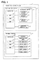
- an indoor positioning system 1 of the present embodiment includes a position information output apparatus 2 and a portable terminal 3.
- the positional information output apparatus 2 includes an ultrasonic output device 11, a wireless communication device 12, and a controller 13.
- the ultrasonic output device 11 includes multiple ultrasonic speakers 21, for example, 36 ultrasonic speakers.
- the ultrasonic speaker 21 outputs ultrasonic wave having an ultrasonic output frequency, e.g., 40 kHz.
- the wireless communication device 12 transmits and receives data using a predetermined wireless communication system, e.g., Bluetooth (registered trademark).
- the controller 13 includes a CPU 31, a ROM 32 and a RAM33, and controls the ultrasonic output device 11 and the wireless communication device 12 by executing processing with the CPU 31 based on a program stored in the ROM 32.
- the controller 13 When the controller 13 receives a rewriting request command from a program rewriting apparatus (not shown) via the wireless communication device 12, the controller 13 performs rewriting processing in which a new program transmitted from the program rewriting apparatus through the wireless communication device 12 is written in the ROM 32.
- the portable terminal 3 includes a display device 41, a manipulation input device 42, a GPS (Global Positioning System) receiver 43, a speech input device 44, a communication device 45, an acceleration sensor 46, a geomagnetic sensor 47, and a controller 48.
- a GPS Global Positioning System
- the display device 41 includes a display (not shown) installed in the front face of the case of the portable terminal 3, and displays various images on a display screen of the display.
- the manipulation input device 42 includes a touch panel provided on the display screen of the display device 41 and a switch provided in the periphery of the display screen bf the display device 41.
- the manipulation-input device 42 outputs input manipulation information for specifying the input manipulation made by a user via the touch panel or the switch
- the GPS receiver 43 receives positioning signals (also called herein a GPS positioning signal) transmitted from GPS satellites.
- the speech input device 44 is for inputting a speech uttered by the user during voice communications using the portable terminal 3.
- the speech input device 44 generates an electrical signal representing the inputted speech and outputs the generated electrical signal.
- the communication device 45 performs data communications through a cellular phone communication network.
- the acceleration sensor 46 detects a magnitude and a direction of the acceleration of the portable terminal 3.
- the geomagnetic sensor 47 detects a magnitude and a direction of geomagnetism.
- the controller 48 includes a CPU 51, a ROM 52, and a RAM 53.
- the CPU 51 performs processing based on a program stored in the ROM 52.
- the controller 48 performs a variety of processing based on inputs from the manipulation-input device 42, the GPS receiver 43, the speech input device 44, the communication device 45, the acceleration sensor 46, and the geomagnetic sensor 47, and controls the display device 41 and the communication device 45.
- the positional information output apparatus 2 is provided to a ceiling CL of an indoor space and outputs ultrasonic wave downward from the ceiling CL.
- the positional information output apparatuses 2 are arranged in a two dimensional matrix form on a plane defining the ceiling CL of the indoor space.
- the controller 13 controls the ultrasonic output device 11 and the ultrasonic output device 11 outputs the ultrasonic wave that is modulated so that the maximum value or the minimum value (see FIG. 4 for the maximum point Pmx and the minimum point Pmn) of the ultrasonic wave having the ultrasonic wave output frequency Fu (see FIG.4 for the ultrasonic wave period Tu) are changed with a predetermined modulation frequency Fm (see FIG. 4 for the modulation period Td).
- the modulation frequency Fm is selected from among predetermined multiple detectable frequencies.
- the detectable frequencies are frequencies that are detectable by the speech input device 44. In the present embodiment, for example, two detectable frequencies of 17 kHz and 19 kHz are set.
- the detectable frequency is determined so that the integral multiple of the detectable frequency does not coincide with the ultrasonic wave output frequency Fu. This is because when the detectable frequency coincides with the ultrasonic wave output frequency Fu, this makes smaller the amplitude of the ultrasonic wave outputted from the ultrasonic output device 11. For example, two times as large as the 20 kHz is 40 kHz, which coincides with the ultrasonic wave output frequency Fu. For this reason, 20 kHz is excluded from the detectable frequency.
- the controller 13 makes the ultrasonic output device 11 output the ultrasonic wave whose modulation frequency Fm varies in accordance with the installation position information indicating a position (n-th floor, latitude, longitude) where the positional information output apparatus 2 is installed.
- the controller 48 expresses the installation position information by digital data with two or more bits, and divides this digital data on a bit-by-bit basis. For each divided one bit, the controller 48 modulates the ultrasonic wave with the modulation frequency Fm corresponding to the 1 bit data, and sequentially outputs the modulated ultrasonic wave with the ultrasonic output device 11.
- the ultrasonic output device 11 uses the modulation frequency Fm of 19 kHz.
- the ultrasonic output device 11 uses the modulation frequency Fm of 17 kHz.
- the ultrasonic wave outputted from the ultrasonic output device 11 is also called an ultrasonic wave positioning signal.
- the multiple ultrasonic speakers 21 are arranged on a plane surface defining the ceiling CL so as to be symmetrical with respect to the center Os.
- Fig. 6 is a diagram illustrating a sound filed distribution D1 in a direction along a straight line L1 of FIG. 5 and a sound filed distribution D2 in a direction along a straight line L2 of FIG. 5 .
- a region having a high sound pressure level is concentrated in a single spot (see FIG. 6 for a high sound field region R1) and the ultrasound wave outputted from the ultrasonic speakers 21 has high directivity.
- the controller 48 of the portable terminal 3 performs a positioning process. While in operation, the controller 48 repeatedly executes the positioning process.
- the controller 48 first determines whether or not the GPS positioning signal is received with the GPS receiver 43. When the GPS positioning signal is received (YES at S10), the process proceeds to S20. At S20, the controller 48 measures the position of the portable terminal 3 based on the information contained in the received GPS positioning signal. Then, the process proceeds to S70.
- the process proceeds to S30.
- the controller 48 determines whether or not the ultrasonic wave positioning signal is inputted to the speech input device 44.
- the process proceeds to S40.
- the controller 48 performs frequency analysis of the inputted ultrasonic wave positioning signal. The controller 48 thereby acquires the above-described installation position information from the ultrasonic wave positioning signal and designates the position indicated by this installation position information as the position of the portable terminal 3.
- the process proceeds to S70.
- the controller 48 determines at S50 whether or not the positioning signal acquired most recently is the ultrasonic wave positioning signal. When the positioning signal acquired most recently is the GPS positioning signal (NO at S50), the positioning process is ended. When the positioning signal acquired most recently is the ultrasonic wave positioning signal (YES at S50), the process proceeds to S60. At S60, the controller 48 calculates the position of the portable terminal 3 based on detection results of the acceleration sensor 46 and the geomagnetic sensor 47. The process then proceeds to S70.
- the controller 48 displays on the display device 41 the information indicating the position acquired by any one of S20, S40 and S60, and the positioning process is ended.
- the position information output apparatus 2 of the indoor positioning system 1 includes the ultrasonic output device 11 and the controller 13.
- the ultrasonic output device 11 outputs the ultrasonic wave having the ultrasonic output frequency Fu.
- the controller 13 has multiple detectable frequencies (e.g., 19 kHz and 19 kHz in this embodiment) which are within a frequency range detectable by the speech input device 44 of the portable terminal 3 and which are set lower than the ultrasonic wave output frequency Fu.
- the controller 13 sequentially select one detectable frequency as a modulation frequency Fm from among the multiple detectable frequencies, and controls the ultrasonic output device 11 so that a maximum value and a minimum value of the amplitude of the ultrasonic wave vary with the selected modulation frequency Fm.
- the position information output apparatus 2 uses the ultrasonic wave to convey the installation position information to the portable terminal 3.
- the ultrasonic wave has high directivity. Therefore, the position information output apparatus 2 prevents a large difference between the present position indicated by the ultrasonic wave inputted to the speech input device 44 of the portable terminal 3 and the actual position.
- the positional information output apparatus 2 outputs the ultrasonic wave modulated with the modulation frequency Fm, which is detectable by the audio input part 44. For this reason, the portable terminal 3 can acquire the installation position information by detecting the modulation frequency of the ultrasonic wave inputted into the speech input device 44. Therefore, according to the positional information output apparatus 2, it becomes possible to provide the installation position information to the portable terminal 3 without replacing the portable terminal 3. It is noted that the portable terminal 3 can use the speech input device 44, which is originally equipped for a telephone communication function, in order to the input of the ultrasonic wave outputted from the position information output apparatus 2.
- the positional information output apparatus 2 is not required to be connected to a network, a new installation of the positional information output apparatus 2 does not require a network installation construction. Furthermore, when the ultrasonic wave outputted downward from the positional information output apparatus 2 installed on the ceiling is reflected at the floor, there is a low possibility that this reflected wave is inputted into the speech input device 44 of the portable terminal 3. A user of the portable terminal 3 typically manipulates the portable terminal 3 with the display screen facing upward.
- the ultrasonic wave outputted from the positional information output apparatus 2 has high directivity, when the ultrasonic wave is reflected at the floor and reaches an opposite side of the portable terminal 3 from the display screen, this reflected way hardly reaches the speech input device 44 disposed on a display screen side of the portable terminal 3.
- the portable terminal 3 detects the modulation frequency Fm of the ultrasonic wave inputted into the audio input device 44, and acquires the installation position information from the ultrasonic wave based on the detected modulation frequency Fm (S40).
- the ultrasonic output frequency Fu differs from the integral multiple of the modulation frequency Fm. Therefore, a decrease in the amplitude of the ultrasonic wave outputted from the positional information output apparatus 2 is suppressed.
- the portable terminal 3 can acquire the installation position information by receiving the ultrasonic wave from the positional information output apparatus 2, and the portable terminal 3 constituted in this way can acquire installation position information, and can obtain the same technical effects as the positional information output apparatus 2.
- the positional information output apparatuses 2 corresponds to an example of a position information providing apparatus.
- the portable terminal 3 corresponds to an example of a position information notifier apparatus.
- the ultrasonic output device 11 corresponds to an example of an ultrasonic wave output means.
- the controller 13 corresponds to an example of a control means.
- S40 corresponds to an example of a position information acquisition means.
- Embodiments are not limited to the above-illustrated embodiment and can have various forms.
- the ultrasonic wave is outputted downward from the ceiling.
- the ultrasonic wave may be outputted outward from the floor.
- the multiple ultrasonic speakers 21 output the same-phase ultrasonic wave.
- the multiple ultrasonic speakers may simultaneously output the normal-phase ultrasonic wave and the reverse-phase ultrasonic wave.
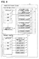
- FIG. 8 is a block diagram illustrating an indoor positioning system 101 configured to output the normal-phase ultrasonic wave and the reverse-phase ultrasonic wave.
- the indoor positioning system 101 differs from the system of the first embodiment in that the indoor positioning system 101 includes ultrasonic speaker groups 16, 17 in place of the multiple (thirty six) ultrasonic speakers 21.
- Each ultrasonic speaker group 16, 17 includes multiple ultrasonic speakers (e.g., eighteen in this embodiment).
- the ultrasonic speaker group 16 includes multiple ultrasonic speakers 26 and the ultrasonic speaker group 17 includes multiple ultrasonic speakers 27.
- the ultrasonic speakers 26, 27 output the ultrasonic wave having the above-described ultrasonic wave output frequency.
- the ultrasonic speakers 26 correspond to an example of a first ultrasonic speaker.
- the ultrasonic speakers 27 correspond to an example of a second ultrasonic speaker.
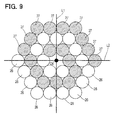
- the multiple ultrasonic speakers 26 constituting the ultrasonic speaker group 16 are arranged in a spiral along a plane surface defining the ceiling (also referred to as a ceiling surface).
- the multiple ultrasonic speakers 27 constituting the ultrasonic speaker group 17 are arranged in a spiral along the ceiling surface.
- an arrangment of the ultrasonic speakers 26 is neither point-symmetry with respect to the center Os nor line symmetry with respect to a straight line passing through the center Os. This is the case in an arrangement of the ultrasonic speakers 27.
- the ultrasonic speaker groups 16, 17 are installed in such a manner that the ultrasonic speaker 26 and the ultrasonic speaker 27 are alternately arranged in an outwardly radial direction from the center of the spiral.
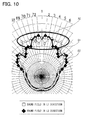
- FIG. 10 is a diagram illustrating a sound field distribution D1 in a direction along a straight line L1 of FIG. 9 and a sound field distribution D2 in a direction along a straight line L2 of FIG. 9 .
- a high sound pressure level region is concentrated in one place (see FIG. 10 for a high sound field R2), and the ultrasonic wave outputted from the ultrasonic speakers 26, 27 has high directivity.
- the high sound field R2 in FIG. 10 is larger than the high sound field R1 of FIG. 6 . That is, when the normal-phase ultrasonic wave and the reverse-phase ultrasonic wave are outputted, the directivity of the ultrasonic wave decreases as compared with cases where all the ultrasonic speakers output the normal-phase ultrasonic wave.
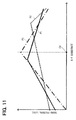
- FIG. 11 is a diagram illustrating the sound pressure level distributions P1, P2 of the indoor positioning system 101 and the sound pressure level distribution P3 of the indoor positioning system 1.
- the sound pressure level distributions P1, P2, P3 denote the sound pressure levels in the vicinity of the floor below the installation position of the ultrasonic output device 11.
- the gradients of the sound pressure levels P1, P2 of the indoor positioning system 101 are smaller than that of the sound pressure level P3 of the indoor positioning system 1. That is, the directivity of the ultrasonic wave in the indoor positioning system 101 is smaller than that in the indoor positioning system 1. This is because the normal-phase ultrasonic wave and the reverse-phase ultrasonic wave weaken each other to decrease their sound pressure levels.
- the sound pressure level distributions P1, P2 denote the sound pressure levels in directions along the straight lines (see FIG. 9 for the straight lines L1, L2) passing through the center Os of FIG. 9 .
- the sound pressure level distributions P1, P2 denote the sound pressure levels along different straight lines.
- the center Od of FIG. 11 opposes to the center Os of FIG. 9 in an upper-lower direction.
- the portable terminal 3 can calculate the position relative to the center Od by detecting the sound pressure level of the ultrasonic wave inputted to the speech input device 44.
- the sound pressure level distribution in the indoor positioning system 1 does not vary depending on directions of straight lines passing through the center Od.
- the sound pressure level gradually decreases with increasing distance from the center Od. Therefore, when the portable terminal 3 is in a one-way movable place such as a narrow width passage where a movable direction is only one way, the portable terminal 3 can calculate the position relative to the center Od by detecting the sound pressure level of the ultrasonic wave inputted to the speech input device 44.
- embodiments and configurations according to the present disclosure have been illustrated, embodiments and configurations according to the present disclosure are not limited to the respective embodiments and configurations described above. Embodiments and configurations obtained by appropriately combining respective technical elements disclosed in different embodiments and configurations also fall within the scope of embodiments and configurations according to the present disclosure.
Abstract
Description
- The present disclosure relates to an indoor position information providing apparatus, a position notifier apparatus and a program for providing position information in an indoor place.
- In order to provide position information in GPS positioning signal undetectable places such as an indoor place or an underground shopping center, a known system includes an indoor transmitter. The indoor transmitter is installed in the indoor place to transmit a positioning signal indicating an indoor position to a portable terminal (e.g.,
JP 4296302B US 2009/0115661 A ). - The inventor of the present application has found that the technology described in
Patent Literature 1 involves the following disadvantage. In order for the portable terminal to receive the positioning signal from the indoor transmitter, all of the existing typical portable terminals should be replaced. - The present disclosure is made in view of the foregoing. It is an object of the present disclosure to provide a technology that enables positioning in an indoor place without replacing portable terminals.
- According to a first aspect of the present disclosure, there is provided a position information providing apparatus for providing present position information indicating a present position to a position notifier apparatus having a function to notify the present position. The position information providing apparatus comprises an ultrasonic wave output device and a controller.
- The ultrasonic wave output device outputs ultrasonic wave having a predetermined ultrasonic frequency. The controller has a plurality of predetermined detectable frequencies which are within a frequency range detectable by a speech input device of the position notifier apparatus and which are lower than the ultrasonic wave frequency. The controller sequentially selects one detectable frequency as a modulation frequency from among the plurality of detectable frequencies in accordance with contents of the present position information, and controls the ultrasonic wave output device so that a maximum value or a minimum value of amplitude of the ultrasonic wave varies with the selected modulation frequency.
- According to the above configuration, the position information providing apparatus uses the ultrasonic wave to convey the present position information to the position notifier apparatus. The ultrasonic wave has high directivity. Therefore, the position information providing apparatus can minimize a difference between the actual present position of the position notifier apparatus and the present position indicated by the ultrasonic wave inputted to the speech input device of the position notifier apparatus.
- Moreover, in accordance with the contents of the present position information, the position information providing apparatus outputs the ultrasonic wave modulated with the modulation frequency, wherein the modulation frequency is detectable by the speech input device. Accordingly, the position notifier apparatus can acquire the present position information by detecting the modulation frequency of the ultrasonic wave inputted to the speech input device.
- Therefore, according to the above position notifier apparatus, it becomes possible to provide the present position information to the position notifier apparatus without replacement of position notifier apparatuses. This is because the speech input device originally equipped in the position notifier apparatus is usable to the input of the ultrasonic wave outputted from the position information providing apparatus. Moreover, because each position information providing is not required to be connected to a network, it is unnecessary to install the network when newly installing the position information providing apparatus.
- According to a second aspect of the present disclosure, there is provided a position notifier apparatus having a function to notify a present position. The position notifier apparatus comprises a speech input device and a position information acquisition device. The speech input device inputs the ultrasonic wave outputted from the position information providing apparatus. The position information acquisition device detects the modulation frequency of the ultrasonic wave inputted to the speech input device, and acquires the present position from the ultrasonic wave based on the detected modulation frequency.
- The above position notifier apparatus can acquire the present position information by receiving the ultrasonic wave from the position information providing apparatus, and can provide substantially the same technical advantages as the position information providing apparatus.
- According to a third aspect of the present disclosure, there is provided a program that causes a computer to function as the position information acquisition device of the position notifier apparatus. The computer controlled by the program constitutes a part of the position notifier apparatus and can provide substantially the same technical advantages as the position notifier apparatus.
- The program may be stored in a non-transitory computer readable storage medium and may be executed by a computer. The storage medium may be a portable storage medium or a non-transitory storage medium pre-installed in the computer. Alternatively, the program may be downloaded to a computer via a network.
- The above and other objects, features and advantages of the present disclosure will become more apparent from the below-described detailed description made with reference to the accompanying drawings, in which:
-
FIG. 1 is a block diagram illustrating a configuration of an indoor positioning system; -
FIG. 2 is a side view illustrating an installation position of a position information output apparatus; -
FIG. 3 is a plane view illustrating the installation position of the position information output apparatus; -
FIG. 4 is a diagram illustrating waveforms of ultrasonic wave outputted from an ultrasonic wave output device; -
FIG. 5 is a plane view illustrating an arrangement of ultrasonic speakers; -
FIG. 6 is a diagram illustrating a sound field distribution of ultrasonic wave in the indoor positioning system; -
FIG. 7 is a flowchart illustrating a positioning process; -
FIG. 8 is a block diagram illustrating an indoor positioning system according to a modified embodiment; -
FIG. 9 is a plane view illustrating an arrangement of ultrasonic speakers; -
FIG. 10 is a diagram illustrating a sound field distribution of the ultrasonic wave in the indoor positioning system; and -
FIG. 11 is a diagram illustrating sound pressure level distributions. - Embodiments will be described with reference to the drawings.
- As shown in
FIG. 1 , anindoor positioning system 1 of the present embodiment includes a positioninformation output apparatus 2 and aportable terminal 3. - The positional
information output apparatus 2 includes anultrasonic output device 11, awireless communication device 12, and acontroller 13. Theultrasonic output device 11 includes multipleultrasonic speakers 21, for example, 36 ultrasonic speakers. Theultrasonic speaker 21 outputs ultrasonic wave having an ultrasonic output frequency, e.g., 40 kHz. - The
wireless communication device 12 transmits and receives data using a predetermined wireless communication system, e.g., Bluetooth (registered trademark). Thecontroller 13 includes aCPU 31, aROM 32 and a RAM33, and controls theultrasonic output device 11 and thewireless communication device 12 by executing processing with theCPU 31 based on a program stored in theROM 32. - When the
controller 13 receives a rewriting request command from a program rewriting apparatus (not shown) via thewireless communication device 12, thecontroller 13 performs rewriting processing in which a new program transmitted from the program rewriting apparatus through thewireless communication device 12 is written in theROM 32. - The
portable terminal 3 includes adisplay device 41, amanipulation input device 42, a GPS (Global Positioning System)receiver 43, aspeech input device 44, acommunication device 45, anacceleration sensor 46, ageomagnetic sensor 47, and acontroller 48. - The
display device 41 includes a display (not shown) installed in the front face of the case of theportable terminal 3, and displays various images on a display screen of the display. Themanipulation input device 42 includes a touch panel provided on the display screen of thedisplay device 41 and a switch provided in the periphery of the display screen bf thedisplay device 41. The manipulation-input device 42 outputs input manipulation information for specifying the input manipulation made by a user via the touch panel or the switch - The
GPS receiver 43 receives positioning signals (also called herein a GPS positioning signal) transmitted from GPS satellites. Thespeech input device 44 is for inputting a speech uttered by the user during voice communications using theportable terminal 3. Thespeech input device 44 generates an electrical signal representing the inputted speech and outputs the generated electrical signal. - The
communication device 45 performs data communications through a cellular phone communication network. Theacceleration sensor 46 detects a magnitude and a direction of the acceleration of theportable terminal 3. Thegeomagnetic sensor 47 detects a magnitude and a direction of geomagnetism. - The
controller 48 includes aCPU 51, aROM 52, and aRAM 53. TheCPU 51 performs processing based on a program stored in theROM 52. Thecontroller 48 performs a variety of processing based on inputs from the manipulation-input device 42, theGPS receiver 43, thespeech input device 44, thecommunication device 45, theacceleration sensor 46, and thegeomagnetic sensor 47, and controls thedisplay device 41 and thecommunication device 45. - As shown in
FIG. 2 , the positionalinformation output apparatus 2 is provided to a ceiling CL of an indoor space and outputs ultrasonic wave downward from the ceiling CL. As shown inFIG. 3 , the positionalinformation output apparatuses 2 are arranged in a two dimensional matrix form on a plane defining the ceiling CL of the indoor space. - As shown in FIG. 54, the
controller 13 controls theultrasonic output device 11 and theultrasonic output device 11 outputs the ultrasonic wave that is modulated so that the maximum value or the minimum value (seeFIG. 4 for the maximum point Pmx and the minimum point Pmn) of the ultrasonic wave having the ultrasonic wave output frequency Fu (seeFIG.4 for the ultrasonic wave period Tu) are changed with a predetermined modulation frequency Fm (seeFIG. 4 for the modulation period Td). The modulation frequency Fm is selected from among predetermined multiple detectable frequencies. The detectable frequencies are frequencies that are detectable by thespeech input device 44. In the present embodiment, for example, two detectable frequencies of 17 kHz and 19 kHz are set. The detectable frequency is determined so that the integral multiple of the detectable frequency does not coincide with the ultrasonic wave output frequency Fu. This is because when the detectable frequency coincides with the ultrasonic wave output frequency Fu, this makes smaller the amplitude of the ultrasonic wave outputted from theultrasonic output device 11. For example, two times as large as the 20 kHz is 40 kHz, which coincides with the ultrasonic wave output frequency Fu. For this reason, 20 kHz is excluded from the detectable frequency. - The
controller 13 makes theultrasonic output device 11 output the ultrasonic wave whose modulation frequency Fm varies in accordance with the installation position information indicating a position (n-th floor, latitude, longitude) where the positionalinformation output apparatus 2 is installed. For example, thecontroller 48 expresses the installation position information by digital data with two or more bits, and divides this digital data on a bit-by-bit basis. For each divided one bit, thecontroller 48 modulates the ultrasonic wave with the modulation frequency Fm corresponding to the 1 bit data, and sequentially outputs the modulated ultrasonic wave with theultrasonic output device 11. - For example, for the data representing "1 ", the
ultrasonic output device 11 uses the modulation frequency Fm of 19 kHz. For the data representing "0", theultrasonic output device 11 uses the modulation frequency Fm of 17 kHz. In the present disclosure, the ultrasonic wave outputted from theultrasonic output device 11 is also called an ultrasonic wave positioning signal. - As shown in
FIG. 5 , the multipleultrasonic speakers 21 are arranged on a plane surface defining the ceiling CL so as to be symmetrical with respect to the center Os. -
Fig. 6 is a diagram illustrating a sound filed distribution D1 in a direction along a straight line L1 ofFIG. 5 and a sound filed distribution D2 in a direction along a straight line L2 ofFIG. 5 . As shown inFIG. 6 , a region having a high sound pressure level is concentrated in a single spot (seeFIG. 6 for a high sound field region R1) and the ultrasound wave outputted from theultrasonic speakers 21 has high directivity. - In this indoor positioning system, 1, the
controller 48 of theportable terminal 3 performs a positioning process. While in operation, thecontroller 48 repeatedly executes the positioning process. - As shown in
FIG. 7 , at S10, thecontroller 48 first determines whether or not the GPS positioning signal is received with theGPS receiver 43. When the GPS positioning signal is received (YES at S10), the process proceeds to S20. At S20, thecontroller 48 measures the position of theportable terminal 3 based on the information contained in the received GPS positioning signal. Then, the process proceeds to S70. - When no GPS positioning signal is received (NO at S10), the process proceeds to S30. At S30, the
controller 48 determines whether or not the ultrasonic wave positioning signal is inputted to thespeech input device 44. When the ultrasonic wave positioning signal is inputted (YES at S30), the process proceeds to S40. At S40, thecontroller 48 performs frequency analysis of the inputted ultrasonic wave positioning signal. Thecontroller 48 thereby acquires the above-described installation position information from the ultrasonic wave positioning signal and designates the position indicated by this installation position information as the position of theportable terminal 3. After S40, the process proceeds to S70. - When the ultrasonic wave positioning signal is not inputted (NO at S30), the
controller 48 determines at S50 whether or not the positioning signal acquired most recently is the ultrasonic wave positioning signal. When the positioning signal acquired most recently is the GPS positioning signal (NO at S50), the positioning process is ended. When the positioning signal acquired most recently is the ultrasonic wave positioning signal (YES at S50), the process proceeds to S60. At S60, thecontroller 48 calculates the position of theportable terminal 3 based on detection results of theacceleration sensor 46 and thegeomagnetic sensor 47. The process then proceeds to S70. - At S70, the
controller 48 displays on thedisplay device 41 the information indicating the position acquired by any one of S20, S40 and S60, and the positioning process is ended. - The position
information output apparatus 2 of theindoor positioning system 1 includes theultrasonic output device 11 and thecontroller 13. - The
ultrasonic output device 11 outputs the ultrasonic wave having the ultrasonic output frequency Fu. Thecontroller 13 has multiple detectable frequencies (e.g., 19 kHz and 19 kHz in this embodiment) which are within a frequency range detectable by thespeech input device 44 of theportable terminal 3 and which are set lower than the ultrasonic wave output frequency Fu. In accordance with contents of the installation position information, thecontroller 13 sequentially select one detectable frequency as a modulation frequency Fm from among the multiple detectable frequencies, and controls theultrasonic output device 11 so that a maximum value and a minimum value of the amplitude of the ultrasonic wave vary with the selected modulation frequency Fm. - The position
information output apparatus 2 uses the ultrasonic wave to convey the installation position information to theportable terminal 3. The ultrasonic wave has high directivity. Therefore, the positioninformation output apparatus 2 prevents a large difference between the present position indicated by the ultrasonic wave inputted to thespeech input device 44 of theportable terminal 3 and the actual position. - Furthermore, in accordance with the contents of the installation position information, the positional
information output apparatus 2 outputs the ultrasonic wave modulated with the modulation frequency Fm, which is detectable by theaudio input part 44. For this reason, theportable terminal 3 can acquire the installation position information by detecting the modulation frequency of the ultrasonic wave inputted into thespeech input device 44. Therefore, according to the positionalinformation output apparatus 2, it becomes possible to provide the installation position information to theportable terminal 3 without replacing theportable terminal 3. It is noted that theportable terminal 3 can use thespeech input device 44, which is originally equipped for a telephone communication function, in order to the input of the ultrasonic wave outputted from the positioninformation output apparatus 2. Furthermore, since the positionalinformation output apparatus 2 is not required to be connected to a network, a new installation of the positionalinformation output apparatus 2 does not require a network installation construction. Furthermore, when the ultrasonic wave outputted downward from the positionalinformation output apparatus 2 installed on the ceiling is reflected at the floor, there is a low possibility that this reflected wave is inputted into thespeech input device 44 of theportable terminal 3. A user of theportable terminal 3 typically manipulates theportable terminal 3 with the display screen facing upward. Because the ultrasonic wave outputted from the positionalinformation output apparatus 2 has high directivity, when the ultrasonic wave is reflected at the floor and reaches an opposite side of theportable terminal 3 from the display screen, this reflected way hardly reaches thespeech input device 44 disposed on a display screen side of theportable terminal 3. - Moreover, the
portable terminal 3 detects the modulation frequency Fm of the ultrasonic wave inputted into theaudio input device 44, and acquires the installation position information from the ultrasonic wave based on the detected modulation frequency Fm (S40). The ultrasonic output frequency Fu differs from the integral multiple of the modulation frequency Fm. Therefore, a decrease in the amplitude of the ultrasonic wave outputted from the positionalinformation output apparatus 2 is suppressed. - The
portable terminal 3 can acquire the installation position information by receiving the ultrasonic wave from the positionalinformation output apparatus 2, and theportable terminal 3 constituted in this way can acquire installation position information, and can obtain the same technical effects as the positionalinformation output apparatus 2. - In the above-illustrated embodiment, the positional
information output apparatuses 2 corresponds to an example of a position information providing apparatus. Theportable terminal 3 corresponds to an example of a position information notifier apparatus. Theultrasonic output device 11 corresponds to an example of an ultrasonic wave output means. Thecontroller 13 corresponds to an example of a control means. S40 corresponds to an example of a position information acquisition means. - Embodiments are not limited to the above-illustrated embodiment and can have various forms.
- For example, in the above embodiment, the ultrasonic wave is outputted downward from the ceiling. Alternatively, the ultrasonic wave may be outputted outward from the floor.
- In the above embodiment, the multiple
ultrasonic speakers 21 output the same-phase ultrasonic wave. Alternatively the multiple ultrasonic speakers may simultaneously output the normal-phase ultrasonic wave and the reverse-phase ultrasonic wave.FIG. 8 is a block diagram illustrating anindoor positioning system 101 configured to output the normal-phase ultrasonic wave and the reverse-phase ultrasonic wave. - As shown in
FIG. 8 , theindoor positioning system 101 differs from the system of the first embodiment in that theindoor positioning system 101 includesultrasonic speaker groups ultrasonic speakers 21. Eachultrasonic speaker group ultrasonic speaker group 16 includes multipleultrasonic speakers 26 and theultrasonic speaker group 17 includes multipleultrasonic speakers 27. Theultrasonic speakers - The
ultrasonic speakers 26 correspond to an example of a first ultrasonic speaker. Theultrasonic speakers 27 correspond to an example of a second ultrasonic speaker. - As shown in
FIG. 9 , the multipleultrasonic speakers 26 constituting theultrasonic speaker group 16 are arranged in a spiral along a plane surface defining the ceiling (also referred to as a ceiling surface). Similarly, the multipleultrasonic speakers 27 constituting theultrasonic speaker group 17 are arranged in a spiral along the ceiling surface. Specifically, an arrangment of theultrasonic speakers 26 is neither point-symmetry with respect to the center Os nor line symmetry with respect to a straight line passing through the center Os. This is the case in an arrangement of theultrasonic speakers 27. - The
ultrasonic speaker groups ultrasonic speaker 26 and theultrasonic speaker 27 are alternately arranged in an outwardly radial direction from the center of the spiral. The normal-phase ultrasonic wave and the reverse-phase ultrasonic wave, which respectively are outputted from theultrasonic speaker 26 and theultrasonic speaker 27 adjacent to each other, weaken sound pressure levels each other. -
FIG. 10 is a diagram illustrating a sound field distribution D1 in a direction along a straight line L1 ofFIG. 9 and a sound field distribution D2 in a direction along a straight line L2 ofFIG. 9 . As shown inFIG. 10 , a high sound pressure level region is concentrated in one place (seeFIG. 10 for a high sound field R2), and the ultrasonic wave outputted from theultrasonic speakers FIG. 10 is larger than the high sound field R1 ofFIG. 6 . That is, when the normal-phase ultrasonic wave and the reverse-phase ultrasonic wave are outputted, the directivity of the ultrasonic wave decreases as compared with cases where all the ultrasonic speakers output the normal-phase ultrasonic wave. -
FIG. 11 is a diagram illustrating the sound pressure level distributions P1, P2 of theindoor positioning system 101 and the sound pressure level distribution P3 of theindoor positioning system 1. The sound pressure level distributions P1, P2, P3 denote the sound pressure levels in the vicinity of the floor below the installation position of theultrasonic output device 11. - The gradients of the sound pressure levels P1, P2 of the
indoor positioning system 101 are smaller than that of the sound pressure level P3 of theindoor positioning system 1. That is, the directivity of the ultrasonic wave in theindoor positioning system 101 is smaller than that in theindoor positioning system 1. This is because the normal-phase ultrasonic wave and the reverse-phase ultrasonic wave weaken each other to decrease their sound pressure levels. - The sound pressure level distributions P1, P2 denote the sound pressure levels in directions along the straight lines (see
FIG. 9 for the straight lines L1, L2) passing through the center Os ofFIG. 9 . The sound pressure level distributions P1, P2 denote the sound pressure levels along different straight lines. The center Od ofFIG. 11 opposes to the center Os ofFIG. 9 in an upper-lower direction. - As illustrated by the sound pressure level distributions P1, P2 of
FIG. 11 , the sound pressure level distribution in theindoor positioning system 101 varies depending on directions of straight lines passing through the center Od. Therefore, theportable terminal 3 can calculate the position relative to the center Od by detecting the sound pressure level of the ultrasonic wave inputted to thespeech input device 44. - As illustrated by the sound pressure level distribution P3 of
FIG. 11 , the sound pressure level distribution in theindoor positioning system 1 does not vary depending on directions of straight lines passing through the center Od. However, in the sound pressure level distribution P3, the sound pressure level gradually decreases with increasing distance from the center Od. Therefore, when theportable terminal 3 is in a one-way movable place such as a narrow width passage where a movable direction is only one way, theportable terminal 3 can calculate the position relative to the center Od by detecting the sound pressure level of the ultrasonic wave inputted to thespeech input device 44. - Although embodiments and configurations according to the present disclosure have been illustrated, embodiments and configurations according to the present disclosure are not limited to the respective embodiments and configurations described above. Embodiments and configurations obtained by appropriately combining respective technical elements disclosed in different embodiments and configurations also fall within the scope of embodiments and configurations according to the present disclosure.
Claims (6)
- A position information providing apparatus for providing present position information indicating a present position to a position notifier apparatus (3) having a function to notify the present position, the position information providing apparatus comprising:an ultrasonic wave output device (11) that outputs ultrasonic wave having a predetermined ultrasonic frequency;a controller (13) that
has a plurality of predetermined detectable frequencies which are within a frequency range detectable by a speech input device (44) of the position notifier apparatus (3) and which are lower than the ultrasonic wave frequency,
sequentially selects one detectable frequency as a modulation frequency from among the plurality of detectable frequencies in accordance with contents of the present position information, and
controls the ultrasonic wave output device (11) so that a maximum value or a minimum value of amplitude of the ultrasonic wave varies with the selected modulation frequency. - The position information providing apparatus according to claim 1, wherein
the ultrasonic wave output device (11) includes
a plurality of first ultrasonic speakers (26) for outputting the ultrasonic wave that is normal-phase, and
a plurality of second ultrasonic speakers (27) for outputting the ultrasonic wave that is reverse-phase;
the plurality of first ultrasonic speakers (26) are arranged in an outward spiral from a predetermined center point along an installation surface, wherein the installation surface is perpendicular to an ultrasonic wave output direction in which the ultrasonic wave output device (11) outputs the ultrasonic wave;
the plurality of second ultrasonic speakers (27) are arranged in an outward spiral from the predetermined center point along the installation surface; and
the plurality of first ultrasonic speakers (26) and the plurality of second ultrasonic speakers (27) are alternately arranged in an outwardly radial direction from the predetermined center point. - The position information providing apparatus according to claim 1 or claim 2, wherein,
the ultrasonic wave frequency differs from each integral multiple of the modulation frequency. - A position notifier apparatus having a function to notify a present position, the position notifier apparatus comprising:an speech input device (44) for inputting ultrasonic wave outputted from the position information providing apparatus recited in any one of claims 1-3; anda position information acquisition device (S40) that
detects the modulation frequency of the ultrasonic wave inputted to the speech input device (44), and
acquires the present position from the ultrasonic wave based on the detected modulation frequency. - A program that causes a computer to function as the position information acquisition device of the position notifier apparatus (3) recited in claim 4.
- A non-transitory computer readable storage medium storing the program recited in claim 5.
Applications Claiming Priority (1)
| Application Number | Priority Date | Filing Date | Title |
|---|---|---|---|
| JP2014131371A JP2016008940A (en) | 2014-06-26 | 2014-06-26 | Positional information providing device, position notification device, and program |
Publications (2)
| Publication Number | Publication Date |
|---|---|
| EP2963439A1 true EP2963439A1 (en) | 2016-01-06 |
| EP2963439B1 EP2963439B1 (en) | 2020-03-04 |
Family
ID=53442614
Family Applications (1)
| Application Number | Title | Priority Date | Filing Date |
|---|---|---|---|
| EP15172713.8A Active EP2963439B1 (en) | 2014-06-26 | 2015-06-18 | Indoor position information providing apparatus, position notifier apparatus and program |
Country Status (4)
| Country | Link |
|---|---|
| US (1) | US9869747B2 (en) |
| EP (1) | EP2963439B1 (en) |
| JP (1) | JP2016008940A (en) |
| CN (1) | CN105223550A (en) |
Families Citing this family (3)
| Publication number | Priority date | Publication date | Assignee | Title |
|---|---|---|---|---|
| US10142782B2 (en) | 2016-07-14 | 2018-11-27 | United Parcel Service Of America, Inc. | Internal location address and automatic routing of intra-facility movement |
| KR101876122B1 (en) * | 2017-03-17 | 2018-07-06 | 황건수 | A supporting body inserted inside packaging bag and packaging bag package comprising thereof |
| CN108613678A (en) * | 2018-05-02 | 2018-10-02 | 桂林电子科技大学 | Indoor navigation sound positioning system and method based on Beidou navigation node |
Citations (5)
| Publication number | Priority date | Publication date | Assignee | Title |
|---|---|---|---|---|
| US20020167417A1 (en) * | 2001-05-10 | 2002-11-14 | Welles Kenneth Brakeley | Location system using retransmission of identifying information |
| US20090115661A1 (en) | 2006-04-04 | 2009-05-07 | Gnss Technologies Inc. | Positional information providing system, positional information providing apparatus and transmitter |
| US20090154294A1 (en) * | 2007-12-17 | 2009-06-18 | Electronics And Telecommunications Research Institute | Method and system for recognizing location by using sound sources with different frequencies |
| WO2013108243A1 (en) * | 2012-01-18 | 2013-07-25 | Weisman Israel | Hybrid-based system and method for indoor localization |
| US20140043943A1 (en) * | 2012-08-13 | 2014-02-13 | Symbol Technologies, Inc. | Ultrasonic locationing system using regional addressing with ultrasonic tones |
Family Cites Families (16)
| Publication number | Priority date | Publication date | Assignee | Title |
|---|---|---|---|---|
| US7663502B2 (en) * | 1992-05-05 | 2010-02-16 | Intelligent Technologies International, Inc. | Asset system control arrangement and method |
| US6205224B1 (en) * | 1996-05-17 | 2001-03-20 | The Boeing Company | Circularly symmetric, zero redundancy, planar array having broad frequency range applications |
| EP1158478A3 (en) * | 1996-07-25 | 2003-11-12 | Matsushita Electric Industrial Co., Ltd | Mobile unit detection system with a mobile unit and mobile unit detection devices |
| EP1617179B1 (en) * | 2000-12-08 | 2007-09-19 | Matsushita Electric Industrial Co., Ltd. | Position information identifier providing system, and position information identifier transmitting method and device |
| AU2002230887A1 (en) * | 2000-12-15 | 2002-06-24 | Polycom, Inc. | System and method for device co-location discrimination |
| WO2002073357A2 (en) * | 2001-03-09 | 2002-09-19 | Radianse, Inc. | A system and method for performing object association using a location tracking system |
| US7298275B2 (en) * | 2002-09-27 | 2007-11-20 | Rockwell Automation Technologies, Inc. | Machine associating method and apparatus |
| US7272456B2 (en) * | 2003-01-24 | 2007-09-18 | Rockwell Automation Technologies, Inc. | Position based machine control in an industrial automation environment |
| US7671718B2 (en) * | 2004-01-27 | 2010-03-02 | Turner Richard H | Method and apparatus for detection and tracking of objects within a defined area |
| US7251535B2 (en) * | 2004-02-06 | 2007-07-31 | Rockwell Automation Technologies, Inc. | Location based diagnostics method and apparatus |
| CA2578653A1 (en) * | 2004-07-29 | 2006-02-09 | Kevin Ferguson | A human movement measurement system |
| US7333018B2 (en) * | 2005-07-25 | 2008-02-19 | Honeywell International Inc. | Asset location system with enhanced accuracy |
| AU2007221976B2 (en) * | 2006-10-19 | 2009-12-24 | Polycom, Inc. | Ultrasonic camera tracking system and associated methods |
| JP2009159390A (en) * | 2007-12-27 | 2009-07-16 | Fujitsu Fsas Inc | Location system and location method |
| JP4725643B2 (en) * | 2008-12-22 | 2011-07-13 | ソニー株式会社 | SOUND OUTPUT DEVICE, COMMUNICATION DEVICE, SOUND OUTPUT METHOD, AND PROGRAM |
| JP6171752B2 (en) * | 2013-09-06 | 2017-08-02 | 株式会社デンソー | Noise reduction device |
-
2014
- 2014-06-26 JP JP2014131371A patent/JP2016008940A/en active Pending
-
2015
- 2015-06-18 EP EP15172713.8A patent/EP2963439B1/en active Active
- 2015-06-22 US US14/745,816 patent/US9869747B2/en not_active Expired - Fee Related
- 2015-06-26 CN CN201510362658.1A patent/CN105223550A/en active Pending
Patent Citations (6)
| Publication number | Priority date | Publication date | Assignee | Title |
|---|---|---|---|---|
| US20020167417A1 (en) * | 2001-05-10 | 2002-11-14 | Welles Kenneth Brakeley | Location system using retransmission of identifying information |
| US20090115661A1 (en) | 2006-04-04 | 2009-05-07 | Gnss Technologies Inc. | Positional information providing system, positional information providing apparatus and transmitter |
| JP4296302B2 (en) | 2006-04-04 | 2009-07-15 | 測位衛星技術株式会社 | Position information providing system and mobile phone |
| US20090154294A1 (en) * | 2007-12-17 | 2009-06-18 | Electronics And Telecommunications Research Institute | Method and system for recognizing location by using sound sources with different frequencies |
| WO2013108243A1 (en) * | 2012-01-18 | 2013-07-25 | Weisman Israel | Hybrid-based system and method for indoor localization |
| US20140043943A1 (en) * | 2012-08-13 | 2014-02-13 | Symbol Technologies, Inc. | Ultrasonic locationing system using regional addressing with ultrasonic tones |
Also Published As
| Publication number | Publication date |
|---|---|
| CN105223550A (en) | 2016-01-06 |
| US9869747B2 (en) | 2018-01-16 |
| JP2016008940A (en) | 2016-01-18 |
| EP2963439B1 (en) | 2020-03-04 |
| US20150378001A1 (en) | 2015-12-31 |
Similar Documents
| Publication | Publication Date | Title |
|---|---|---|
| US9641622B2 (en) | Master device for using connection attribute of electronic accessories connections to facilitate locating an accessory | |
| US20120156997A1 (en) | Bluetooth communication method and terminal adopting same | |
| KR20140059492A (en) | Apparatus and method for outputting a location of a wireless charging device in a portabil terminal | |
| US10051412B2 (en) | Locational information transmission system, locational information transmission apparatus, and information processing device | |
| US9869747B2 (en) | Indoor position information providing apparatus, position notifier apparatus and program | |
| EP2832121B1 (en) | Contextual awareness using relative positions of mobile devices | |
| US7065382B2 (en) | Wireless terminal having a scanner for issuing an alert when within the range of a target wireless terminal | |
| US8504076B2 (en) | Location positioning apparatus, location positioning method, and location positioning program | |
| KR101637483B1 (en) | Apparatus and method for recognizing peripheral device using distance and intimacy | |
| JP6076027B2 (en) | Navigation system | |
| CN105737837A (en) | Positioning navigation method, positioning navigation apparatus and positioning navigation system | |
| EP2034466A1 (en) | In-vehicle communication apparatus, in-vehicle communication method, and in-vehicle communication program | |
| JP2015122580A (en) | Portable electronic apparatus, control method and control program | |
| KR20150130845A (en) | Apparatus and Device for Position Measuring of Electronic Apparatuses | |
| JP6378024B2 (en) | Portable terminal, information notification method, information notification program, and computer-readable information recording medium | |
| EP2999298B1 (en) | Mobile information processing device, information processing system, and information processing method | |
| JP2017143358A (en) | Mobile terminal device, management device, and program | |
| JP6171046B1 (en) | Electronic device, control method, and control program | |
| JP6411404B2 (en) | Electronic device, control method, and control program | |
| JP2016025472A (en) | Terminal device, communication system and communication method | |
| JP2017161347A (en) | Position detection device, position detection system, position detection method, and position detection program | |
| JP2014192867A (en) | Radio communication device, radio communication system, radio communication method and radio communication program | |
| JP6746652B2 (en) | Electronic device, electronic device control method, and electronic device control program | |
| JP6462056B2 (en) | Electronic device, roadside machine, control method, and control program | |
| JP2018031668A (en) | Electronic apparatus, method for control, and control program |
Legal Events
| Date | Code | Title | Description |
|---|---|---|---|
| PUAI | Public reference made under article 153(3) epc to a published international application that has entered the european phase |
Free format text: ORIGINAL CODE: 0009012 |
|
| AK | Designated contracting states |
Kind code of ref document: A1 Designated state(s): AL AT BE BG CH CY CZ DE DK EE ES FI FR GB GR HR HU IE IS IT LI LT LU LV MC MK MT NL NO PL PT RO RS SE SI SK SM TR |
|
| AX | Request for extension of the european patent |
Extension state: BA ME |
|
| 17P | Request for examination filed |
Effective date: 20160209 |
|
| RBV | Designated contracting states (corrected) |
Designated state(s): AL AT BE BG CH CY CZ DE DK EE ES FI FR GB GR HR HU IE IS IT LI LT LU LV MC MK MT NL NO PL PT RO RS SE SI SK SM TR |
|
| STAA | Information on the status of an ep patent application or granted ep patent |
Free format text: STATUS: EXAMINATION IS IN PROGRESS |
|
| 17Q | First examination report despatched |
Effective date: 20180409 |
|
| GRAP | Despatch of communication of intention to grant a patent |
Free format text: ORIGINAL CODE: EPIDOSNIGR1 |
|
| STAA | Information on the status of an ep patent application or granted ep patent |
Free format text: STATUS: GRANT OF PATENT IS INTENDED |
|
| INTG | Intention to grant announced |
Effective date: 20190917 |
|
| GRAS | Grant fee paid |
Free format text: ORIGINAL CODE: EPIDOSNIGR3 |
|
| GRAA | (expected) grant |
Free format text: ORIGINAL CODE: 0009210 |
|
| STAA | Information on the status of an ep patent application or granted ep patent |
Free format text: STATUS: THE PATENT HAS BEEN GRANTED |
|
| AK | Designated contracting states |
Kind code of ref document: B1 Designated state(s): AL AT BE BG CH CY CZ DE DK EE ES FI FR GB GR HR HU IE IS IT LI LT LU LV MC MK MT NL NO PL PT RO RS SE SI SK SM TR |
|
| RAP1 | Party data changed (applicant data changed or rights of an application transferred) |
Owner name: DENSO CORPORATION |
|
| REG | Reference to a national code |
Ref country code: GB Ref legal event code: FG4D |
|
| RIN1 | Information on inventor provided before grant (corrected) |
Inventor name: NAKAYAMA, TOSHIAKI Inventor name: INOUE, TORU |
|
| REG | Reference to a national code |
Ref country code: CH Ref legal event code: EP |
|
| REG | Reference to a national code |
Ref country code: AT Ref legal event code: REF Ref document number: 1241028 Country of ref document: AT Kind code of ref document: T Effective date: 20200315 |
|
| REG | Reference to a national code |
Ref country code: DE Ref legal event code: R096 Ref document number: 602015048030 Country of ref document: DE |
|
| REG | Reference to a national code |
Ref country code: IE Ref legal event code: FG4D |
|
| PG25 | Lapsed in a contracting state [announced via postgrant information from national office to epo] |
Ref country code: FI Free format text: LAPSE BECAUSE OF FAILURE TO SUBMIT A TRANSLATION OF THE DESCRIPTION OR TO PAY THE FEE WITHIN THE PRESCRIBED TIME-LIMIT Effective date: 20200304 Ref country code: NO Free format text: LAPSE BECAUSE OF FAILURE TO SUBMIT A TRANSLATION OF THE DESCRIPTION OR TO PAY THE FEE WITHIN THE PRESCRIBED TIME-LIMIT Effective date: 20200604 Ref country code: RS Free format text: LAPSE BECAUSE OF FAILURE TO SUBMIT A TRANSLATION OF THE DESCRIPTION OR TO PAY THE FEE WITHIN THE PRESCRIBED TIME-LIMIT Effective date: 20200304 |
|
| PGFP | Annual fee paid to national office [announced via postgrant information from national office to epo] |
Ref country code: DE Payment date: 20200618 Year of fee payment: 6 Ref country code: FR Payment date: 20200619 Year of fee payment: 6 |
|
| REG | Reference to a national code |
Ref country code: NL Ref legal event code: MP Effective date: 20200304 |
|
| PG25 | Lapsed in a contracting state [announced via postgrant information from national office to epo] |
Ref country code: GR Free format text: LAPSE BECAUSE OF FAILURE TO SUBMIT A TRANSLATION OF THE DESCRIPTION OR TO PAY THE FEE WITHIN THE PRESCRIBED TIME-LIMIT Effective date: 20200605 Ref country code: BG Free format text: LAPSE BECAUSE OF FAILURE TO SUBMIT A TRANSLATION OF THE DESCRIPTION OR TO PAY THE FEE WITHIN THE PRESCRIBED TIME-LIMIT Effective date: 20200604 Ref country code: HR Free format text: LAPSE BECAUSE OF FAILURE TO SUBMIT A TRANSLATION OF THE DESCRIPTION OR TO PAY THE FEE WITHIN THE PRESCRIBED TIME-LIMIT Effective date: 20200304 Ref country code: SE Free format text: LAPSE BECAUSE OF FAILURE TO SUBMIT A TRANSLATION OF THE DESCRIPTION OR TO PAY THE FEE WITHIN THE PRESCRIBED TIME-LIMIT Effective date: 20200304 Ref country code: LV Free format text: LAPSE BECAUSE OF FAILURE TO SUBMIT A TRANSLATION OF THE DESCRIPTION OR TO PAY THE FEE WITHIN THE PRESCRIBED TIME-LIMIT Effective date: 20200304 |
|
| REG | Reference to a national code |
Ref country code: LT Ref legal event code: MG4D |
|
| PG25 | Lapsed in a contracting state [announced via postgrant information from national office to epo] |
Ref country code: NL Free format text: LAPSE BECAUSE OF FAILURE TO SUBMIT A TRANSLATION OF THE DESCRIPTION OR TO PAY THE FEE WITHIN THE PRESCRIBED TIME-LIMIT Effective date: 20200304 |
|
| PG25 | Lapsed in a contracting state [announced via postgrant information from national office to epo] |
Ref country code: ES Free format text: LAPSE BECAUSE OF FAILURE TO SUBMIT A TRANSLATION OF THE DESCRIPTION OR TO PAY THE FEE WITHIN THE PRESCRIBED TIME-LIMIT Effective date: 20200304 Ref country code: CZ Free format text: LAPSE BECAUSE OF FAILURE TO SUBMIT A TRANSLATION OF THE DESCRIPTION OR TO PAY THE FEE WITHIN THE PRESCRIBED TIME-LIMIT Effective date: 20200304 Ref country code: IS Free format text: LAPSE BECAUSE OF FAILURE TO SUBMIT A TRANSLATION OF THE DESCRIPTION OR TO PAY THE FEE WITHIN THE PRESCRIBED TIME-LIMIT Effective date: 20200704 Ref country code: SK Free format text: LAPSE BECAUSE OF FAILURE TO SUBMIT A TRANSLATION OF THE DESCRIPTION OR TO PAY THE FEE WITHIN THE PRESCRIBED TIME-LIMIT Effective date: 20200304 Ref country code: SM Free format text: LAPSE BECAUSE OF FAILURE TO SUBMIT A TRANSLATION OF THE DESCRIPTION OR TO PAY THE FEE WITHIN THE PRESCRIBED TIME-LIMIT Effective date: 20200304 Ref country code: LT Free format text: LAPSE BECAUSE OF FAILURE TO SUBMIT A TRANSLATION OF THE DESCRIPTION OR TO PAY THE FEE WITHIN THE PRESCRIBED TIME-LIMIT Effective date: 20200304 Ref country code: RO Free format text: LAPSE BECAUSE OF FAILURE TO SUBMIT A TRANSLATION OF THE DESCRIPTION OR TO PAY THE FEE WITHIN THE PRESCRIBED TIME-LIMIT Effective date: 20200304 Ref country code: PT Free format text: LAPSE BECAUSE OF FAILURE TO SUBMIT A TRANSLATION OF THE DESCRIPTION OR TO PAY THE FEE WITHIN THE PRESCRIBED TIME-LIMIT Effective date: 20200729 Ref country code: EE Free format text: LAPSE BECAUSE OF FAILURE TO SUBMIT A TRANSLATION OF THE DESCRIPTION OR TO PAY THE FEE WITHIN THE PRESCRIBED TIME-LIMIT Effective date: 20200304 |
|
| REG | Reference to a national code |
Ref country code: AT Ref legal event code: MK05 Ref document number: 1241028 Country of ref document: AT Kind code of ref document: T Effective date: 20200304 |
|
| PGFP | Annual fee paid to national office [announced via postgrant information from national office to epo] |
Ref country code: IT Payment date: 20200625 Year of fee payment: 6 |
|
| REG | Reference to a national code |
Ref country code: DE Ref legal event code: R097 Ref document number: 602015048030 Country of ref document: DE |
|
| PLBE | No opposition filed within time limit |
Free format text: ORIGINAL CODE: 0009261 |
|
| STAA | Information on the status of an ep patent application or granted ep patent |
Free format text: STATUS: NO OPPOSITION FILED WITHIN TIME LIMIT |
|
| PG25 | Lapsed in a contracting state [announced via postgrant information from national office to epo] |
Ref country code: DK Free format text: LAPSE BECAUSE OF FAILURE TO SUBMIT A TRANSLATION OF THE DESCRIPTION OR TO PAY THE FEE WITHIN THE PRESCRIBED TIME-LIMIT Effective date: 20200304 Ref country code: MC Free format text: LAPSE BECAUSE OF FAILURE TO SUBMIT A TRANSLATION OF THE DESCRIPTION OR TO PAY THE FEE WITHIN THE PRESCRIBED TIME-LIMIT Effective date: 20200304 Ref country code: AT Free format text: LAPSE BECAUSE OF FAILURE TO SUBMIT A TRANSLATION OF THE DESCRIPTION OR TO PAY THE FEE WITHIN THE PRESCRIBED TIME-LIMIT Effective date: 20200304 |
|
| REG | Reference to a national code |
Ref country code: CH Ref legal event code: PL |
|
| 26N | No opposition filed |
Effective date: 20201207 |
|
| PG25 | Lapsed in a contracting state [announced via postgrant information from national office to epo] |
Ref country code: PL Free format text: LAPSE BECAUSE OF FAILURE TO SUBMIT A TRANSLATION OF THE DESCRIPTION OR TO PAY THE FEE WITHIN THE PRESCRIBED TIME-LIMIT Effective date: 20200304 Ref country code: SI Free format text: LAPSE BECAUSE OF FAILURE TO SUBMIT A TRANSLATION OF THE DESCRIPTION OR TO PAY THE FEE WITHIN THE PRESCRIBED TIME-LIMIT Effective date: 20200304 |
|
| GBPC | Gb: european patent ceased through non-payment of renewal fee |
Effective date: 20200618 |
|
| PG25 | Lapsed in a contracting state [announced via postgrant information from national office to epo] |
Ref country code: LU Free format text: LAPSE BECAUSE OF NON-PAYMENT OF DUE FEES Effective date: 20200618 |
|
| REG | Reference to a national code |
Ref country code: BE Ref legal event code: MM Effective date: 20200630 |
|
| PG25 | Lapsed in a contracting state [announced via postgrant information from national office to epo] |
Ref country code: LI Free format text: LAPSE BECAUSE OF NON-PAYMENT OF DUE FEES Effective date: 20200630 Ref country code: GB Free format text: LAPSE BECAUSE OF NON-PAYMENT OF DUE FEES Effective date: 20200618 Ref country code: IE Free format text: LAPSE BECAUSE OF NON-PAYMENT OF DUE FEES Effective date: 20200618 Ref country code: CH Free format text: LAPSE BECAUSE OF NON-PAYMENT OF DUE FEES Effective date: 20200630 |
|
| PG25 | Lapsed in a contracting state [announced via postgrant information from national office to epo] |
Ref country code: BE Free format text: LAPSE BECAUSE OF NON-PAYMENT OF DUE FEES Effective date: 20200630 |
|
| REG | Reference to a national code |
Ref country code: DE Ref legal event code: R119 Ref document number: 602015048030 Country of ref document: DE |
|
| PG25 | Lapsed in a contracting state [announced via postgrant information from national office to epo] |
Ref country code: DE Free format text: LAPSE BECAUSE OF NON-PAYMENT OF DUE FEES Effective date: 20220101 |
|
| PG25 | Lapsed in a contracting state [announced via postgrant information from national office to epo] |
Ref country code: TR Free format text: LAPSE BECAUSE OF FAILURE TO SUBMIT A TRANSLATION OF THE DESCRIPTION OR TO PAY THE FEE WITHIN THE PRESCRIBED TIME-LIMIT Effective date: 20200304 Ref country code: MT Free format text: LAPSE BECAUSE OF FAILURE TO SUBMIT A TRANSLATION OF THE DESCRIPTION OR TO PAY THE FEE WITHIN THE PRESCRIBED TIME-LIMIT Effective date: 20200304 Ref country code: FR Free format text: LAPSE BECAUSE OF NON-PAYMENT OF DUE FEES Effective date: 20210630 Ref country code: CY Free format text: LAPSE BECAUSE OF FAILURE TO SUBMIT A TRANSLATION OF THE DESCRIPTION OR TO PAY THE FEE WITHIN THE PRESCRIBED TIME-LIMIT Effective date: 20200304 |
|
| PG25 | Lapsed in a contracting state [announced via postgrant information from national office to epo] |
Ref country code: MK Free format text: LAPSE BECAUSE OF FAILURE TO SUBMIT A TRANSLATION OF THE DESCRIPTION OR TO PAY THE FEE WITHIN THE PRESCRIBED TIME-LIMIT Effective date: 20200304 Ref country code: AL Free format text: LAPSE BECAUSE OF FAILURE TO SUBMIT A TRANSLATION OF THE DESCRIPTION OR TO PAY THE FEE WITHIN THE PRESCRIBED TIME-LIMIT Effective date: 20200304 |
|
| PG25 | Lapsed in a contracting state [announced via postgrant information from national office to epo] |
Ref country code: IT Free format text: LAPSE BECAUSE OF NON-PAYMENT OF DUE FEES Effective date: 20210618 |