EP2966451A2 - Method for sensing and sensor - Google Patents
Method for sensing and sensor Download PDFInfo
- Publication number
- EP2966451A2 EP2966451A2 EP15175929.7A EP15175929A EP2966451A2 EP 2966451 A2 EP2966451 A2 EP 2966451A2 EP 15175929 A EP15175929 A EP 15175929A EP 2966451 A2 EP2966451 A2 EP 2966451A2
- Authority
- EP
- European Patent Office
- Prior art keywords
- radiation
- diaphragm element
- light
- force
- electrical
- Prior art date
- Legal status (The legal status is an assumption and is not a legal conclusion. Google has not performed a legal analysis and makes no representation as to the accuracy of the status listed.)
- Withdrawn
Links
- 238000000034 method Methods 0.000 title claims abstract description 31
- 230000005855 radiation Effects 0.000 claims abstract description 131
- 238000012546 transfer Methods 0.000 claims abstract description 29
- 238000006243 chemical reaction Methods 0.000 claims abstract description 28
- 230000005670 electromagnetic radiation Effects 0.000 claims abstract description 13
- 230000033001 locomotion Effects 0.000 claims abstract description 12
- 238000001514 detection method Methods 0.000 claims abstract description 9
- 230000005520 electrodynamics Effects 0.000 claims abstract description 5
- 230000008859 change Effects 0.000 claims description 19
- 230000003287 optical effect Effects 0.000 claims description 19
- 230000001419 dependent effect Effects 0.000 claims description 18
- 230000005540 biological transmission Effects 0.000 claims description 17
- 230000009021 linear effect Effects 0.000 claims description 17
- 239000013307 optical fiber Substances 0.000 claims description 10
- 229910052710 silicon Inorganic materials 0.000 claims description 8
- 239000010703 silicon Substances 0.000 claims description 8
- 238000005452 bending Methods 0.000 claims description 7
- 238000006073 displacement reaction Methods 0.000 claims description 6
- 239000011521 glass Substances 0.000 claims description 5
- 238000005530 etching Methods 0.000 claims description 4
- 239000003365 glass fiber Substances 0.000 claims description 4
- 238000000576 coating method Methods 0.000 claims description 3
- 239000000835 fiber Substances 0.000 claims description 3
- 239000011159 matrix material Substances 0.000 claims description 3
- 239000000725 suspension Substances 0.000 claims description 3
- 239000010720 hydraulic oil Substances 0.000 claims description 2
- 239000000696 magnetic material Substances 0.000 claims description 2
- 230000009022 nonlinear effect Effects 0.000 claims description 2
- 239000004033 plastic Substances 0.000 claims description 2
- 239000002096 quantum dot Substances 0.000 claims description 2
- 238000005096 rolling process Methods 0.000 claims description 2
- 239000011248 coating agent Substances 0.000 claims 1
- 230000003068 static effect Effects 0.000 claims 1
- 230000004907 flux Effects 0.000 abstract description 29
- 230000001133 acceleration Effects 0.000 abstract description 9
- 230000001939 inductive effect Effects 0.000 abstract 1
- 238000012986 modification Methods 0.000 abstract 1
- 230000004048 modification Effects 0.000 abstract 1
- XUIMIQQOPSSXEZ-UHFFFAOYSA-N Silicon Chemical group [Si] XUIMIQQOPSSXEZ-UHFFFAOYSA-N 0.000 description 7
- 238000013461 design Methods 0.000 description 5
- 238000010586 diagram Methods 0.000 description 5
- 230000000694 effects Effects 0.000 description 5
- 239000000463 material Substances 0.000 description 5
- 238000005259 measurement Methods 0.000 description 5
- VYZAMTAEIAYCRO-UHFFFAOYSA-N Chromium Chemical compound [Cr] VYZAMTAEIAYCRO-UHFFFAOYSA-N 0.000 description 4
- 230000005284 excitation Effects 0.000 description 4
- 238000004519 manufacturing process Methods 0.000 description 4
- 238000003860 storage Methods 0.000 description 4
- 230000004888 barrier function Effects 0.000 description 3
- 238000011156 evaluation Methods 0.000 description 3
- 230000007704 transition Effects 0.000 description 3
- RZVAJINKPMORJF-UHFFFAOYSA-N Acetaminophen Chemical compound CC(=O)NC1=CC=C(O)C=C1 RZVAJINKPMORJF-UHFFFAOYSA-N 0.000 description 2
- 230000006978 adaptation Effects 0.000 description 2
- 230000002238 attenuated effect Effects 0.000 description 2
- 230000015572 biosynthetic process Effects 0.000 description 2
- 239000004020 conductor Substances 0.000 description 2
- 238000013016 damping Methods 0.000 description 2
- 238000011161 development Methods 0.000 description 2
- 230000005484 gravity Effects 0.000 description 2
- 238000002955 isolation Methods 0.000 description 2
- 239000004973 liquid crystal related substance Substances 0.000 description 2
- 238000012545 processing Methods 0.000 description 2
- 239000005297 pyrex Substances 0.000 description 2
- 238000000926 separation method Methods 0.000 description 2
- 238000007493 shaping process Methods 0.000 description 2
- 230000008054 signal transmission Effects 0.000 description 2
- 230000003595 spectral effect Effects 0.000 description 2
- 230000002123 temporal effect Effects 0.000 description 2
- 235000012431 wafers Nutrition 0.000 description 2
- 239000013543 active substance Substances 0.000 description 1
- 239000000654 additive Substances 0.000 description 1
- 230000000996 additive effect Effects 0.000 description 1
- 230000003321 amplification Effects 0.000 description 1
- 229910052804 chromium Inorganic materials 0.000 description 1
- 239000011651 chromium Substances 0.000 description 1
- 239000003086 colorant Substances 0.000 description 1
- 238000012888 cubic function Methods 0.000 description 1
- 238000009826 distribution Methods 0.000 description 1
- 230000005684 electric field Effects 0.000 description 1
- 239000003623 enhancer Substances 0.000 description 1
- 238000000105 evaporative light scattering detection Methods 0.000 description 1
- 230000007274 generation of a signal involved in cell-cell signaling Effects 0.000 description 1
- 239000012535 impurity Substances 0.000 description 1
- 238000002329 infrared spectrum Methods 0.000 description 1
- 238000009413 insulation Methods 0.000 description 1
- 239000012212 insulator Substances 0.000 description 1
- 238000012886 linear function Methods 0.000 description 1
- 238000011326 mechanical measurement Methods 0.000 description 1
- 239000000203 mixture Substances 0.000 description 1
- 238000003199 nucleic acid amplification method Methods 0.000 description 1
- 230000010363 phase shift Effects 0.000 description 1
- 238000012887 quadratic function Methods 0.000 description 1
- 230000004044 response Effects 0.000 description 1
- 230000000284 resting effect Effects 0.000 description 1
- 230000000630 rising effect Effects 0.000 description 1
- 238000005070 sampling Methods 0.000 description 1
- 238000004088 simulation Methods 0.000 description 1
- 238000001228 spectrum Methods 0.000 description 1
- 238000012360 testing method Methods 0.000 description 1
- 230000009466 transformation Effects 0.000 description 1
- 238000000844 transformation Methods 0.000 description 1
- XLYOFNOQVPJJNP-UHFFFAOYSA-N water Substances O XLYOFNOQVPJJNP-UHFFFAOYSA-N 0.000 description 1
Images
Classifications
-
- G—PHYSICS
- G01—MEASURING; TESTING
- G01R—MEASURING ELECTRIC VARIABLES; MEASURING MAGNETIC VARIABLES
- G01R33/00—Arrangements or instruments for measuring magnetic variables
- G01R33/02—Measuring direction or magnitude of magnetic fields or magnetic flux
- G01R33/028—Electrodynamic magnetometers
- G01R33/0283—Electrodynamic magnetometers in which a current or voltage is generated due to relative movement of conductor and magnetic field
-
- G—PHYSICS
- G01—MEASURING; TESTING
- G01D—MEASURING NOT SPECIALLY ADAPTED FOR A SPECIFIC VARIABLE; ARRANGEMENTS FOR MEASURING TWO OR MORE VARIABLES NOT COVERED IN A SINGLE OTHER SUBCLASS; TARIFF METERING APPARATUS; MEASURING OR TESTING NOT OTHERWISE PROVIDED FOR
- G01D5/00—Mechanical means for transferring the output of a sensing member; Means for converting the output of a sensing member to another variable where the form or nature of the sensing member does not constrain the means for converting; Transducers not specially adapted for a specific variable
- G01D5/26—Mechanical means for transferring the output of a sensing member; Means for converting the output of a sensing member to another variable where the form or nature of the sensing member does not constrain the means for converting; Transducers not specially adapted for a specific variable characterised by optical transfer means, i.e. using infrared, visible, or ultraviolet light
- G01D5/32—Mechanical means for transferring the output of a sensing member; Means for converting the output of a sensing member to another variable where the form or nature of the sensing member does not constrain the means for converting; Transducers not specially adapted for a specific variable characterised by optical transfer means, i.e. using infrared, visible, or ultraviolet light with attenuation or whole or partial obturation of beams of light
- G01D5/34—Mechanical means for transferring the output of a sensing member; Means for converting the output of a sensing member to another variable where the form or nature of the sensing member does not constrain the means for converting; Transducers not specially adapted for a specific variable characterised by optical transfer means, i.e. using infrared, visible, or ultraviolet light with attenuation or whole or partial obturation of beams of light the beams of light being detected by photocells
-
- G—PHYSICS
- G01—MEASURING; TESTING
- G01K—MEASURING TEMPERATURE; MEASURING QUANTITY OF HEAT; THERMALLY-SENSITIVE ELEMENTS NOT OTHERWISE PROVIDED FOR
- G01K5/00—Measuring temperature based on the expansion or contraction of a material
- G01K5/48—Measuring temperature based on the expansion or contraction of a material the material being a solid
- G01K5/56—Measuring temperature based on the expansion or contraction of a material the material being a solid constrained so that expansion or contraction causes a deformation of the solid
- G01K5/62—Measuring temperature based on the expansion or contraction of a material the material being a solid constrained so that expansion or contraction causes a deformation of the solid the solid body being formed of compounded strips or plates, e.g. bimetallic strip
- G01K5/70—Measuring temperature based on the expansion or contraction of a material the material being a solid constrained so that expansion or contraction causes a deformation of the solid the solid body being formed of compounded strips or plates, e.g. bimetallic strip specially adapted for indicating or recording
-
- G—PHYSICS
- G01—MEASURING; TESTING
- G01L—MEASURING FORCE, STRESS, TORQUE, WORK, MECHANICAL POWER, MECHANICAL EFFICIENCY, OR FLUID PRESSURE
- G01L1/00—Measuring force or stress, in general
- G01L1/25—Measuring force or stress, in general using wave or particle radiation, e.g. X-rays, microwaves, neutrons
-
- G—PHYSICS
- G01—MEASURING; TESTING
- G01P—MEASURING LINEAR OR ANGULAR SPEED, ACCELERATION, DECELERATION, OR SHOCK; INDICATING PRESENCE, ABSENCE, OR DIRECTION, OF MOVEMENT
- G01P15/00—Measuring acceleration; Measuring deceleration; Measuring shock, i.e. sudden change of acceleration
- G01P15/02—Measuring acceleration; Measuring deceleration; Measuring shock, i.e. sudden change of acceleration by making use of inertia forces using solid seismic masses
- G01P15/08—Measuring acceleration; Measuring deceleration; Measuring shock, i.e. sudden change of acceleration by making use of inertia forces using solid seismic masses with conversion into electric or magnetic values
- G01P15/093—Measuring acceleration; Measuring deceleration; Measuring shock, i.e. sudden change of acceleration by making use of inertia forces using solid seismic masses with conversion into electric or magnetic values by photoelectric pick-up
-
- G—PHYSICS
- G01—MEASURING; TESTING
- G01R—MEASURING ELECTRIC VARIABLES; MEASURING MAGNETIC VARIABLES
- G01R15/00—Details of measuring arrangements of the types provided for in groups G01R17/00 - G01R29/00, G01R33/00 - G01R33/26 or G01R35/00
- G01R15/14—Adaptations providing voltage or current isolation, e.g. for high-voltage or high-current networks
- G01R15/24—Adaptations providing voltage or current isolation, e.g. for high-voltage or high-current networks using light-modulating devices
-
- G—PHYSICS
- G01—MEASURING; TESTING
- G01R—MEASURING ELECTRIC VARIABLES; MEASURING MAGNETIC VARIABLES
- G01R33/00—Arrangements or instruments for measuring magnetic variables
- G01R33/02—Measuring direction or magnitude of magnetic fields or magnetic flux
- G01R33/032—Measuring direction or magnitude of magnetic fields or magnetic flux using magneto-optic devices, e.g. Faraday or Cotton-Mouton effect
-
- G—PHYSICS
- G01—MEASURING; TESTING
- G01R—MEASURING ELECTRIC VARIABLES; MEASURING MAGNETIC VARIABLES
- G01R33/00—Arrangements or instruments for measuring magnetic variables
- G01R33/02—Measuring direction or magnitude of magnetic fields or magnetic flux
- G01R33/038—Measuring direction or magnitude of magnetic fields or magnetic flux using permanent magnets, e.g. balances, torsion devices
- G01R33/0385—Measuring direction or magnitude of magnetic fields or magnetic flux using permanent magnets, e.g. balances, torsion devices in relation with magnetic force measurements
-
- G—PHYSICS
- G01—MEASURING; TESTING
- G01R—MEASURING ELECTRIC VARIABLES; MEASURING MAGNETIC VARIABLES
- G01R15/00—Details of measuring arrangements of the types provided for in groups G01R17/00 - G01R29/00, G01R33/00 - G01R33/26 or G01R35/00
- G01R15/14—Adaptations providing voltage or current isolation, e.g. for high-voltage or high-current networks
- G01R15/22—Adaptations providing voltage or current isolation, e.g. for high-voltage or high-current networks using light-emitting devices, e.g. LED, optocouplers
Definitions
- the present invention relates to a metrological method for detecting, converting and manipulating motion-causing, force or torque-based and optical input signals in either amplitude-modulated light signals or comparable amplitude-modulated electromagnetic radiation signals and for further conversion thereof into electrical signals.
- the present invention relates to transducers for carrying out the method.
- the transducer is a micromechanical assembly, i. the movements are limited to very small distances, preferably less than 1 mm, for example 10 ⁇ m, or very small angle changes, preferably by an angular range of less than 30 °.
- the transducer modifies optical signals by optomechanically modulating electromagnetic radiation paths.
- such a transducer can also be referred to as a micro-optomechanical sensor.
- Electrically controlled light sources in particular light-emitting diodes: these can convert electrical input variables into light of a specific spectral range, as a result of which electrical signals can also be transmitted via light waves to other locations (via free space, waveguides or via light guides, such as glass fibers). Infrared diodes are also mentioned here.
- Photodiodes, phototransistors, photovoltaic elements, radiation detectors and the like allow the conversion of light or certain electromagnetic waves into electrical signals (current / voltage).
- Light modulators these modulate polarized light using optically active substances (liquid crystals). This can be amplified or even phase-modulated by an electrical signal, depending on the design of a light beam. Here, the alignment of the liquid crystals by an electrical voltage for the modulation effect.
- Optocouplers these devices convert electrical input quantities into light intensities by driving an electrically operated light source and the light signal by means of photodiodes or phototransistors back into electrical output variables. Optocouplers serve the electrical isolation of electrical signals.
- Optical absolute encoders these output a unique digital code for each positioning position or each angular position to be detected, which is represented by a binary line pattern through a plurality of miniaturized light barriers.
- An example is in US 4,385,234 shown where a coding disc with a drive axis relative to an optics with a light source and a sensor matrix is rotatably mounted in a housing.
- this device usually designed as an iris diaphragm, allows the mechanical change of the opening of a light passage on lenses of photographic equipment or film cameras.
- a special diaphragm shape for use as a variable optical damper is shown in FIG US 6,404,970 wherein a plurality of openings in a component is regularly arranged. In this case, the opening diameter of the openings in an expansion direction of the component increases steadily, whereby the component has a position-dependent light transmission.
- Another integrated variable optical damper is in FR 2 839 060 published, wherein a comb drive a deflection mirror in response to the applied voltage in a Introduces light passage, whereby a portion of the amount of light in the light passage is deflected out of the light channel.
- vibration sensor formed by a hybrid opto-micro-electro-mechanical system is published.
- An illustration shows a rectangular diaphragm element movably mounted on meandering springs. This is made of a silicon structure from an SOI (silicon-on-insulator) wafer and has square etched openings.
- comb structures are attached to the longitudinal sides, the function of which is not explained in detail in this publication.
- the invention is now intended to remedy the aforementioned disadvantages of the prior art and allow additional functions. Therefore, a method has been sought which, in addition to already described and known applications and transfer functions, enables potential-isolated, isolated measurement of an input variable defined by the device from a set of now different possible input variables.
- Possible transfer functions are to be determinable by a precalculation of the effect of the shape of the position or angular position-dependent sectional area of a suitably selected light projection with the location-dependent suitably selected light transmission.
- the device for carrying out the method should have very specially selected cross-sectional shape designs of the light apertures in the movably mounted aperture element, as well as paired, specially selected shapes or patterns for the light projection.
- the position or rotational position of the measuring mass should be optically detectable by the measuring mass is also effective as part of a mechanical light modulation system, which transmits more or less light depending on the relative position of its components.
- At least one transfer function is formed by the shaping of the components of the mechanical light modulation system or the modulation system for the electromagnetic waves, in such a way that at least one useful signal manipulation takes place via the path or angular position of the measuring mass detection.
- the signal manipulation can, for example, have the task of compensating the non-linearities of input variables and of distance- or angle-dependent opposing forces, or deliberately consciously incorporating particular nonlinearities piecewise, for example different slopes depending on the distance or angle section of the movement space (eg for different intensity measurement ranges).
- Measuring instruments require a robust, reliable and as accurate as possible conversion of an input variable into an output variable.
- the detected signals must be adapted to the measuring system. If the signals are out of range, matching devices are needed. If the signals are too small, they must be amplified, but noise (noise) should be suppressed. If the signals are too large they must first be attenuated. Certain signals behave exponentially, others are e.g. logarithmically perceived (e.g., volume, brightness), which is why the logarithm of the measurand should be appropriately measured and controlled. Some signals are filtered, some are linearized, some are digitized for further processing.
- signal manipulations by suitable designs can achieve modulation (a certain input signal frequency multiplication, eg doubling, tripling), signal full wave or half wave rectification, or dynamic effects known from acoustic manipulation individually, in parallel or in combination, for example that of a compressor, a limiter , or from an enhancer, an expander, or a noise gate.
- Digital signal transformations should be able to be output in parallel.
- At least one path-dependent opposing force should be provided, which compensates for the force to be measured as of a certain deflection of the measuring mass from an initial or rest position.
- a complete electrical decoupling should result. This is of particular importance when the light signal is converted back to electrical but manipulated signals via photoelectric converters.
- the method allows short development times or adaptations of signal transducers with special transmission characteristics.
- the formation of the specifically desired transfer characteristic does not require any electronic components, since the signal manipulation can take place in a dazzling optical way.
- several transmission functions can be formed in parallel in one component and output through several outputs.
- Various transmission characteristics can be summed up by parallel arrangement.
- the output signal of the converter can be fed via optical fibers or waveguides of an evaluation.
- the measured input variables are used directly for the modulation of a light path or the modulation of the transmission path of the electromagnetic wave.
- the light or electromagnetic wave source may or may not be attached to the transducer. It is also possible to supply light guides with light or special guides for the electromagnetic waves to guide these waves to the transducer. In principle, natural lighting (daylight) or artificial room lighting of the environment can also serve as the light source.
- the light source can be modulated. This allows cross modulation and multiplication functions. Several light or wave sources can be used in parallel, even with different spectral components for different zones.
- the object is achieved by a novel method for optomechanical detection and conversion of an input signal to be measured.
- This input signal can be a mechanical, an electrostatic, a magnetic or an electrodynamic variable, which then influences an electromagnetic radiation channel via the intermediate step by conversion into a path signal.
- an input signal dependent electromagnetic output signal e.g. generates a specific luminous flux.
- This can be converted as a result of again via a radiation-sensitive sensor, for example, a photosensor in an electrical signal. This is, for example, a dependent on the input signal electrical DC or AC voltage or a DC or AC.
- an opto-mechanical transfer function is formed, wherein radiation components of an electromagnetic radiation projection, for example of a light projection, are transmitted or shadowed by a special component as a function of its position or its angular position.
- the electromagnetic signals used for this purpose preferably have wavelengths in the range of 100 nm to 10 ⁇ m and are limited in the possible spatial expansion directions. Visible rays of this electromagnetic Radiation projection would show on a plane projection surface a previously defined pattern with at least one outer contour and possibly also unirradiated or shaded areas within the contour. But also for non-visible electromagnetic radiation there are defined impact zones and zones where no radiation is supplied.
- this geometric shape and / or pattern predetermined projection is partly due to a thin flat areal and preferably opaque aperture element and partly by at least one radiation passage at this aperture element, which is aligned frontally against the source of the radiation projection.
- the beam transmission on the diaphragm element has a geometrically predetermined and preferably etched cross-sectional surface shape.
- the optically or photo- or radiation-sensor-detectable output signal for the given relative spatial position (x, y) or relative orientation position ( ⁇ ) is converted into a path or angle of a dependent transmission flow. How much light or radiation penetrates through the specially shaped apertures / radiation passages in the observed frequency spectrum is given by the intersection (or mathematical convolution) of the projected geometric shapes and patterns and the radiation passage cross-sectional areas depending on position or angle. Since more than one sensor can be arranged opposite the light or radiation exit sides of a plurality of radiation passages, a plurality of signals can also be formed from the respective intersections.
- this method according to the invention is suitable for input signals which are based on gravitational force, inertial force, mass moment of inertia or centrifugal force, these forces acting on the mass of the diaphragm element accelerating.
- the device for carrying out the method is the subject of the invention.
- Alternative drive devices for the diaphragm element are preferably mechanical levers (also piezo elements, thermal length changes, bimetallic strip), gear rack pairing, magnets, magnetic materials, coils, electric motor drives.
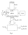
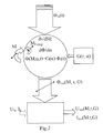
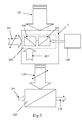
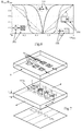
- Fig. 7 For example, the typical structure is shown with the quiescent optical shutter 6, the movable shutter 300 and the quiescent flux (detector) surface.
- a torque-counter-torque pairing for torque-angle conversion may represent an alternative application of the inventive method.
- This is functional in the block diagram Fig. 2 shown.
- the output radiation flux ⁇ out determining variables are then the measured moment M, using the compensation moment M Comp , the angle ⁇ and the modulation of the input radiation flux ⁇ in over time and the shape geometry of the aperture light projection pairing in dependence on the relative rotation angle ⁇ , ⁇ reflects the variable relative position of the radiation projection with respect to the position of the movable diaphragm element and defines itself in a polar coordinate system normal to the main plane of extent of the movable diaphragm by the given r and ⁇ coordinates in a defined range of values (r min ..r .. .r max , ⁇ min ... ⁇ ... ⁇ max ).
- a transfer function G is uniquely described.
- one or more signals can also be manipulated via the iris optical transmission function (s) 100 according to predetermined criteria.
- An example would be an exponential light filter.
- vibrations or movement or torsion signals can be manipulated selectively and form a wide variety of electrical output signals.
- electrostatic drive CombDrive
- electrical signals can be converted directly into amplitudes of the luminous flux or the radiant flux and into electrical signals again via the radiation-sensitive sensor. For this, only a very few different components are required, but a multiplicity of functions can also be formed in parallel. Beyond a common optocoupler functions can be integrated into the optics, which would otherwise be possible only by considerable effort in an electronic circuit.
- FIG. 6 the output signal (normalized representation) is shown for four different apertures (stationary) and apertures (moved to).
- the dashed graph in Fig. 6 shows a linear course corresponding to a pair of square apertures with square apertures corresponding to the rearmost portion Fig. 7 ,
- the aperture is cross-shaped as in the subsequent section in Fig. 7 , so gets the linear course (see thin line in Fig. 6 ) According to the opening width in the direction of movement two different slopes, in the longitudinal beam portion of the cross, the slope is shallower than in the crossbar section.
Abstract
Verfahren zur optomechanischen Erfassung und Wandlung eines mechanischen, elektrostatischen, magnetostatischen oder elektrodynamischen Eingangssignales in amplitudenmodulierte elektromagnetische Strahlungs-Ausgangssignale und daraus strahlungssensorisch gebildete elektrische Ausgangssignale mithilfe einer optomechanisch gebildeten Übertragungsfunktion sowie Vorrichtung zur Durchführung dieses Verfahrens. Die vorgestellte Erfindung betrifft ein Verfahren zur opto-mikromechanischen WegErfassung, zur Signal-Umformung und Veränderung sowie Wandler, die nach diesem Verfahren arbeiten. Dazu dient ein - relativ zur Umgebung und relativ zu definierten Licht- bzw. Strahlungszonen - bewegliches, dünnes flächiges Blendenelement. Mit besonders geformten Durchlässen lässt dieses in Abhängigkeit von der Position mehr oder weniger Licht oder vergleichbare elektromagnetische Strahlung durch. Der Strahlungsanteil (der Lichtstrom), der durch die Durchlässe gelangt, bildet eine Funktion die von der Relativposition bzw. der Relativwinkellage des Blendenelementes zu den Strahlungszonen abhängt. Ein Photo- oder Strahlungsdetektor kann den auftreffenden Strahlungsfluss in elektrische Signale umwandeln. Die gemessenen Größen können Wege oder Winkel, Beschleunigungen, Kräfte, elektrisch oder magnetisch bedingte Bewegungen oder Druck sein. Elektrische oder magnetische Feldstärken, elektrische Spannungen oder Ströme die über aktive kapazitive oder induktive Stellglieder in Bewegungen umgeformt werden, können gemessen werden.Method for the optomechanical detection and conversion of a mechanical, electrostatic, magnetostatic or electrodynamic input signal into amplitude-modulated electromagnetic radiation output signals and radiation-sensorially formed electrical output signals using an opto-mechanically formed transfer function and apparatus for carrying out this method. The present invention relates to a method for opto-micromechanical path detection, signal conversion and modification and converters that operate according to this method. This is done by a - relative to the environment and relative to defined light or radiation zones - movable, thin area diaphragm element. With specially shaped passages, this allows more or less light or comparable electromagnetic radiation, depending on the position. The radiation component (the luminous flux) which passes through the passages forms a function which depends on the relative position or the relative angular position of the diaphragm element to the radiation zones. A photo or radiation detector can convert the incident radiation flux into electrical signals. The measured quantities can be paths or angles, accelerations, forces, electrically or magnetically induced movements or pressure. Electrical or magnetic field strengths, electrical voltages or currents that are transformed into active movements via active capacitive or inductive actuators can be measured.
Description
Verfahren zur optomechanischen Erfassung und Wandlung eines mechanischen, elektrostatischen, magnetostatischen oder elektrodynamischen Eingangssignales in amplitudenmodulierte elektromagnetische Strahlungs-Ausgangssignale und daraus strahlungssensorisch gebildete elektrische Ausgangssignale mithilfe einer opto-mechanisch gebildeten Übertragungsfunktion sowie Vorrichtung zur Durchführung dieses Verfahrens.Method for the optomechanical detection and conversion of a mechanical, electrostatic, magnetostatic or electrodynamic input signal into amplitude-modulated electromagnetic radiation output signals and radiation-sensorially formed electrical output signals using an opto-mechanically formed transfer function and apparatus for carrying out this method.
Die vorliegende Erfindung betrifft ein messtechnisches Verfahren zum Erfassen, Wandeln und Manipulieren von bewegungsverursachenden, kraft- oder drehmomentbasierten und optischen Eingangssignalen in entweder amplitudenmodulierte Licht-Signale oder vergleichbare amplitudenmodulierte elektromagnetische Strahlungssignale sowie zur weiteren Wandlung derselben in elektrische Signale.The present invention relates to a metrological method for detecting, converting and manipulating motion-causing, force or torque-based and optical input signals in either amplitude-modulated light signals or comparable amplitude-modulated electromagnetic radiation signals and for further conversion thereof into electrical signals.
Des Weiteren betrifft die vorliegende Erfindung Wandler zur Durchführung des Verfahrens. Der Wandler ist eine mikromechanische Baugruppe, d.h. die Bewegungen sind auf sehr kleine Strecken, vorzugsweise unter 1 mm, zum Beispiel 10µm, oder sehr geringe Winkeländerungen vorzugsweise um einen Winkelbereich von weniger als 30° eingeschränkt. Zudem verändert der Wandler optische Signale, indem er elektromagnetische Strahlungspfade optomechanisch moduliert. Insofern kann ein solcher Wandler auch als Mikro-Optomechanischer Sensor bezeichnet werden.Furthermore, the present invention relates to transducers for carrying out the method. The transducer is a micromechanical assembly, i. the movements are limited to very small distances, preferably less than 1 mm, for example 10 μm, or very small angle changes, preferably by an angular range of less than 30 °. In addition, the transducer modifies optical signals by optomechanically modulating electromagnetic radiation paths. In this respect, such a transducer can also be referred to as a micro-optomechanical sensor.
Elektrisch angesteuerte Lichtquellen insbesondere Leuchtdioden: diese können elektrische Eingangsgrößen in Licht eines bestimmten spektralen Bereiches wandeln, wodurch sich elektrische Signale auch über Lichtwellen an andere Orte übermitteln lassen (über Freiraum, Wellenleiter oder über Lichtleiter, wie Glasfasern). Infrarotdioden sind hier ebenfalls zu nennen.Electrically controlled light sources, in particular light-emitting diodes: these can convert electrical input variables into light of a specific spectral range, as a result of which electrical signals can also be transmitted via light waves to other locations (via free space, waveguides or via light guides, such as glass fibers). Infrared diodes are also mentioned here.
Photodioden, Phototransistoren, Photovoltaik-Elemente, Strahlungsdetektoren und dergleichen: diese erlauben die Wandlung von Licht oder bestimmte elektromagnetische Wellen in elektrische Signale (Strom/Spannung).Photodiodes, phototransistors, photovoltaic elements, radiation detectors and the like: these allow the conversion of light or certain electromagnetic waves into electrical signals (current / voltage).
Lichtmodulatoren: diese modulieren polarisiertes Licht mithilfe optisch aktiver Substanzen (Flüssigkristallen). Damit kann durch ein elektrisches Signal ein Lichtstrahl je nach Ausführung amplituden oder sogar phasenmoduliert werden. Hierbei dient die Ausrichtung der Flüssigkristalle durch eine elektrische Spannung für den Modulationseffekt.Light modulators: these modulate polarized light using optically active substances (liquid crystals). This can be amplified or even phase-modulated by an electrical signal, depending on the design of a light beam. Here, the alignment of the liquid crystals by an electrical voltage for the modulation effect.
Optokoppler: diese Vorrichtungen wandeln elektrische Eingangsgrößen in Lichtintensitäten durch Ansteuerung einer elektrisch betriebenen Lichtquelle und das Lichtsignal mithilfe von Photodioden oder Phototransistoren zurück in elektrische Ausgangsgrößen. Optokoppler dienen der Potentialtrennung elektrischer Signale.Optocouplers: these devices convert electrical input quantities into light intensities by driving an electrically operated light source and the light signal by means of photodiodes or phototransistors back into electrical output variables. Optocouplers serve the electrical isolation of electrical signals.
Lichtschranken, auch im Infrarotspektrum: diese erlauben die Erfassung von passierenden Objekten quer durch einen Lichtpfad, indem der direkte optische Weg zwischen einer Strahlungsquelle und einem Strahlungssensor unterbrochen wird.Light barriers, also in the infrared spectrum: these allow the detection of passing objects across a light path by the direct optical path between a radiation source and a radiation sensor is interrupted.
Inkrementelle optische Encoder: diese entsprechen kleinen Lichtschranken zur Erfassung von Anzahl von Strichen auf einem ansonsten transparenten Kode-Streifen oder einer Kodierscheibe. Für die Richtungserfassung sind meist zwei zueinander versetzte Strichraster vorgesehen. Diese bilden mit A und B bezeichneten Signale auf Photosensoren. Dadurch ergeben sich Sinus- und Cosinus-Signale bei einem Hell-Dunkel-Hell bzw. Dunkel-Hell-Dunkel Übergang aufgrund des Schattenwurfes des Strichrasters. Solche Encoder dienen der Erfassung von Stellwegen, Drehwinkeln oder Drehzahlen.Incremental optical encoders: these correspond to small light barriers for detecting the number of lines on an otherwise transparent code strip or a coding disk. For the direction detection usually two mutually offset line grids are provided. These form signals labeled A and B on photosensors. This results in sine and cosine signals in a light-dark-bright or dark-light-dark transition due to the shadow cast of the bar screen. Such encoders are used to detect travel ranges, angles of rotation or speeds.
Optische Absolutwert-Encoder: diese geben für jede Stellposition oder jede zu erfassende Winkelstellung einen eindeutigen digitalen Code aus, welcher durch ein binäres Strichmuster durch mehrere miniaturisierte Lichtschranken abgebildet wird. Ein Beispiel ist in
Mechanisch verstellbare fotografische Blende: diese, meist als Irisblende ausgeführte Vorrichtung ermöglicht die mechanische Veränderung der Öffnung eines Lichtdurchlasses bei Objektiven von Foto-Apparaten oder Filmkameras. Eine besondere Blendenform zur Verwendung als veränderlicher optischer Dämpfer ist in
Ein weiterer integrierter variabler optischer Dämpfer ist in
Schließlich muss auf eine eigene Vorveröffentlichung in
Nachteilig bei dieser, den Stand der Technik naheliegend beschreibenden Vorrichtung ist, dass nur eine einzige und auch nur eine ganz bestimmte Weg-Lichtintensitäten-elektrisches Signal (mV/mm) Übertragungsfunktion vorliegt. Es gibt nur einen Auswerte-Phototransistor und somit maximal nur ein analoges elektrisches Ausgangssignal. Die Übertragungskennlinie des Phototransistors ist nicht linear und muss folglich elektronisch korrigiert werden, wenn ein linearer Zusammenhang zwischen Ein- und Ausgangsgröße gewünscht wird. Die Eingangsgrößen beschränken sich hier nur auf mechanische Schwingungsanregung durch Anregung von Vibrationen über das Gehäuse und Neigungen, bzw. Beschleunigung oder Verzögerungen in Richtung der Beweglichkeit des Blendenelementes. Die Beweglichkeit des Blendenelementes ist auf nur eine Richtung beschränkt. Die Dimensionen der Chrom-Blenden sind genau so groß wie die Dimensionen der Aperturen im Silizium-Blendenelement. Dadurch muss die Positionierung exakt erfolgen. Die Lichtintensität über die Fläche ist inhomogen. Auch der Sensor ist sehr groß und mittelt die durch die Öffnungen gelangende Lichtströme. Ein separates Erfassen einzelner Teillichtströme ist hier nicht möglich.A disadvantage of this, the state of the art obvious descriptive device is that there is only a single and only a very specific path light intensity electrical signal (mV / mm) transfer function. There is only one evaluation phototransistor and therefore only one analogue electrical output signal. The transfer characteristic of the phototransistor is non-linear and therefore has to be electronically corrected if a linear relationship between input and output is desired. The input variables are limited here only to mechanical vibration excitation by excitation of vibrations over the housing and inclinations, or acceleration or deceleration in the direction of the mobility of the diaphragm element. The mobility of the diaphragm element is limited to only one direction. The dimensions of the chrome diaphragms are just as large as the dimensions of the apertures in the silicon diaphragm element. As a result, the positioning must be accurate. The light intensity over the surface is inhomogeneous. Also, the sensor is very large and averages the passing through the openings light fluxes. Separate detection of individual partial light flows is not possible here.
Die Erfindung soll nun die genannten Nachteile des Standes der Technik beheben und zusätzliche Funktionen ermöglichen. Es wurde daher ein Verfahren gesucht, welches über bereits beschriebene und bekannte Anwendungen und Übertragungsfunktionen hinaus, ein potentialgetrenntes, isoliertes Messen einer durch die Vorrichtung definierte Eingangsgröße aus einer Menge nunmehr unterschiedlicher möglicher Eingangsgrößen ermöglicht.The invention is now intended to remedy the aforementioned disadvantages of the prior art and allow additional functions. Therefore, a method has been sought which, in addition to already described and known applications and transfer functions, enables potential-isolated, isolated measurement of an input variable defined by the device from a set of now different possible input variables.
Mögliche Übertragungsfunktionen sollen durch eine Vorberechnung der Auswirkung der Form der Positions- oder Winkellage-abhängigen Schnittfläche einer geeignet gewählten Lichtprojektion mit der ortsabhängigen geeignet gewählten Lichtdurchlässigkeit bestimmbar sein. Die Vorrichtung zur Durchführung des Verfahrens soll dazu ganz speziell gewählte Querschnittsformgestaltungen der Lichtdurchlässe im beweglich gelagerten Blendenelement aufweisen, sowie dazu gepaart, speziell gewählte Formen oder Muster für die Lichtprojektion. Die Position oder Drehlage der Messmasse soll optisch erfassbar sein, indem die Messmasse auch als Teil eines mechanischen Lichtmodulationssystems wirksam wird, welches mehr oder weniger Licht in Abhängigkeit der relativen Lage seiner Komponenten durchlässt.Possible transfer functions are to be determinable by a precalculation of the effect of the shape of the position or angular position-dependent sectional area of a suitably selected light projection with the location-dependent suitably selected light transmission. The device for carrying out the method should have very specially selected cross-sectional shape designs of the light apertures in the movably mounted aperture element, as well as paired, specially selected shapes or patterns for the light projection. The position or rotational position of the measuring mass should be optically detectable by the measuring mass is also effective as part of a mechanical light modulation system, which transmits more or less light depending on the relative position of its components.
Wesentlich dabei ist, dass erfindungsgemäß zumindest eine Übertragungsfunktion durch die Formgebung der Komponenten des mechanischen Lichtmodulationssystems bzw. des Modulationssystemes für die elektromagnetischen Wellen gebildet wird, derart, dass über die Weg- oder Winkellage der Messmasse-Erfassung zusätzlich zumindest eine sinnvoll nützbare Signalmanipulation erfolgt.It is essential that, according to the invention, at least one transfer function is formed by the shaping of the components of the mechanical light modulation system or the modulation system for the electromagnetic waves, in such a way that at least one useful signal manipulation takes place via the path or angular position of the measuring mass detection.
In Bezug auf den Stand der Technik gilt dies insbesondere für eine, über eine rein analoge Weg-Lichtstrom-Signal-Übertragung oder über eine bekannte inkrementelles Weg-Pulszahl- oder Position-Absolutwert-Digital-Signalausgabe hinausgehende Manipulation des Lichtes.With respect to the prior art, this applies in particular to a manipulation of the light that goes beyond a purely analogue path-luminous-flux signal transmission or via a known incremental path-pulse-number or position-absolute-value digital signal output.
Die Signalmanipulation kann beispielsweise die Aufgabe haben, die Nichtlinearitäten von Eingangsgrößen und von weg- oder winkelabhängigen Gegenkräften zu kompensieren, oder bewusst bestimmte Nichtlinearitäten auch stückweise bewusst einzubauen, beispielsweise vom Strecken- oder Winkelabschnitt des Bewegungsraumes abhängige unterschiedliche Steigung (z.B. für unterschiedliche Intensitäts -Messbereiche).The signal manipulation can, for example, have the task of compensating the non-linearities of input variables and of distance- or angle-dependent opposing forces, or deliberately consciously incorporating particular nonlinearities piecewise, for example different slopes depending on the distance or angle section of the movement space (eg for different intensity measurement ranges). ,
Im einfachsten Fall ist bereits die Funktion der elektrischen Spannung gegenüber dem Stellweg zweier dazu eingesetzter Kammelektroden als Kammantrieb nichtlinear; bei geringen Abständen ergeben sich höhere elektronische Spannungsänderungen je Wegabschnitt, als bei großen Abständen. Aber auch die Lichtquelle hat häufig inhomogene Verteilung, es müssten Diffusoren das Licht gleichmäßiger verteilen um bei anteilsmäßiger Abschattung auch gleiche Lichtanteile auf dem Lichtsensor zu erhalten. Der Lichtsensor selbst hat ebenfalls in der Regel kein lineares Verhalten.In the simplest case, the function of the electrical voltage with respect to the travel of two comb electrodes used for this purpose is already non-linear as a comb drive; at short intervals, higher electronic voltage changes per path section result than at long distances. But also the light source often has an inhomogeneous distribution, it would have diffusers to distribute the light more evenly to get proportionate shading and the same amount of light on the light sensor. The light sensor itself also usually has no linear behavior.
Das Erfordernis einer Übertragungsfunktion wird heute in elektronischen Schaltungen durch eine mehr oder weniger komplexe Struktur aus Transistoren und passiven Bauelementen gebildet. Dazu ist für die Entwicklung ein Aufwand für Entwurf, Layout und Simulation erforderlich, aber auch für die Fertigung und den Test der elektronischen Struktur. Zudem ist die Genauigkeit dieser Anpassungsmethoden prinzipiell begrenzt. Aufgrund bestimmter Störstellendichte auf Siliziumscheiben, dem Basismaterial für die Gestaltung der elektronischen Struktur, können bestimmte Anteile der erzeugten elektronische Bauteile schon in der Produktion Ausfälle haben, wodurch es zur Produktionsausbeute unter 100% kommt, insbesondere bei größeren Schaltungen.The requirement for a transfer function is today formed in electronic circuits by a more or less complex structure of transistors and passive components. This requires design, layout and simulation effort, but also the fabrication and testing of the electronic structure. In addition, the accuracy of these adaptation methods is limited in principle. Due to certain impurity density on silicon wafers, the base material for the design of the electronic structure can certain parts of the electronic components produced have failures already in production, resulting in a production yield below 100%, especially in larger circuits.
Messgeräte benötigen eine robuste, zuverlässige und möglichst genaue Umsetzung einer Eingangsgröße in eine Ausgangsgröße. Die erfassten Signale müssen an das Messsystem angepasst werden. Sind die Signale außerhalb des Messbereichs werden Anpassungsvorrichtungen benötigt. Sind die Signale zu klein, müssen sie verstärkt werden, dabei sollen aber Störsignale (Rauschen) unterdrückt werden. Sind die Signale zu groß müssen sie zunächst abgeschwächt werden. Bestimmte Signale verhalten sich exponentiell, andere werden z.B. logarithmisch wahrgenommen (z.B. Lautstärke, Helligkeit) weshalb zweckmäßig der Logarithmus der Messgröße gemessen und kontrolliert werden sollte. Manche Signale gehören gefiltert, manche linearisiert, manche werden für die Weiterverarbeitung digitalisiert. Bislang werden für all diese erforderlichen Anpassungen elektronische Schaltungen mit Verstärkern, Abschwächern, Integrierern, Logarithmierern, Vorrichtungen zur Abtastung und Digitalisierung, Kurvenanalysatoren, Frequenzanalysatoren und vieles andere mehr eingesetzt. Dies geschieht deshalb, um für eine bestimmte Eingangsgröße das gewünschte Ausgangssignal zu bekommen. In einem einfachen Fall kann das der Sensor nur eine Grenzwertüberschreitung erfassen (Sicherung, Alarm). Oder eine Betriebsanzeige visualisiert den Wert innerhalb der erlaubten Grenzen. Für komplizierte Anwendungen muss eine nichtlineare Eingangsgröße in ein lineares Ausgangssignal übergeführt werden. Manchmal müssen kleine Signale verstärkt (Expander), größere abgeschwächt (Kompressor) und ganz große Signale begrenzt werden (Limiter). So kann je nach Eingangsgröße eine unterschiedliche Übertragungsfunktion erforderlich sein. Besonders dafür konzipierte Wandler sollen beispielsweise auch mehrere Eingangs-Signalmanipulationen ermöglichen, wie unterschiedliche Verstärkung oder unterschiedliche Phasenverschiebung, parallel an mehreren optischen und/oder elektrischen Ausgängen.Measuring instruments require a robust, reliable and as accurate as possible conversion of an input variable into an output variable. The detected signals must be adapted to the measuring system. If the signals are out of range, matching devices are needed. If the signals are too small, they must be amplified, but noise (noise) should be suppressed. If the signals are too large they must first be attenuated. Certain signals behave exponentially, others are e.g. logarithmically perceived (e.g., volume, brightness), which is why the logarithm of the measurand should be appropriately measured and controlled. Some signals are filtered, some are linearized, some are digitized for further processing. So far, for all of these necessary adjustments, electronic circuits with amplifiers, attenuators, integrators, logarithmers, sampling and digitizing devices, curve analyzers, frequency analyzers, and much more are being used. This is done to get the desired output for a given input. In a simple case, the sensor can detect only a limit violation (fuse, alarm). Or a status display visualizes the value within the permitted limits. For complicated applications, a non-linear input must be converted into a linear output signal. Sometimes small signals have to be amplified (expander), larger attenuated (compressor) and very large signals limited (limiter). Thus, depending on the input variable, a different transfer function may be required. For example, specially designed transducers are intended to enable a plurality of input signal manipulations, such as different amplification or different phase shifts, in parallel at a plurality of optical and / or electrical outputs.
Weitere Signalmanipulationen durch geeignete Ausbildungen können Modulation (eine bestimmte Eingangssignal-Frequenzvervielfachung, z.B. Verdoppelung, Verdreifachung), eine Signalvollweg- oder Halbwellengleichrichtung, oder aus der akustischen Manipulation bekannte Dynamikeffekte einzeln, parallel oder kombiniert erzielen, beispielsweise die eines Kompressors, eines Limiters (Begrenzers), oder von einem Enhancer, einem Expander oder einem Noise Gate. Digitale Signalumformungen sollen parallel zusätzlich ausgegeben werden können.Further signal manipulations by suitable designs can achieve modulation (a certain input signal frequency multiplication, eg doubling, tripling), signal full wave or half wave rectification, or dynamic effects known from acoustic manipulation individually, in parallel or in combination, for example that of a compressor, a limiter , or from an enhancer, an expander, or a noise gate. Digital signal transformations should be able to be output in parallel.
Mögliche Mess-Größen sollen sein: Stellwege, Drehwinkel, Kräfte auf eine kleine Messmasse, wie Gravitationskräfte, Beschleunigungskräfte und folglich auch lineare Beschleunigungen (z.B. Erdbeschleunigung), Fliehkräfte und somit Winkelgeschwindigkeiten (Drehraten), aber auch Neigungen gegenüber Gravitationskräften; darüber hinaus sollen auch Anwendungen möglich sein wo elektrostatische Kräfte zwischen einer Bezugselektrode und einer beweglich gelagerten Elektrode gemessen werden können oder Kräfte die magnetischen Ursprung haben (z.B. zwischen zwei Permanentmagneten, oder zwischen einem Permanentmagneten und einem magnetisierbaren Material, oder aufgrund zumindest einem Strom durchfluteten Leiter wechselwirkend mit einem weiteren stromdurchfluteten Leiter oder einem Permanentmagneten oder magnetisierbarem Material). In allen Fällen der Kraftmessung soll zumindest eine wegabhängige Gegenkraft vorgesehen sein, die ab einer bestimmten Auslenkung der Messmasse aus einer Ausgangs- oder Ruhelage die zu messende Kraft kompensiert. Bei elektrischen Größen, die in mechanische Stellwege umgeformt werden, soll sich eine völlige elektrische Entkopplung ergeben. Das ist insbesondere von Bedeutung, wenn das Lichtsignal über photoelektrische Wandler in elektrische, jedoch manipulierte Signale rückgewandelt wird.Possible measurement variables are: Travel paths, rotation angles, forces on a small measuring mass, such as gravitational forces, acceleration forces and consequently also linear accelerations (eg gravitational acceleration), centrifugal forces and thus angular velocities (rotation rates), but also Inclinations to gravitational forces; In addition, applications are also to be possible where electrostatic forces between a reference electrode and a movably mounted electrode can be measured or forces having magnetic origins (eg between two permanent magnets, or between a permanent magnet and a magnetizable material, or interacting due to at least one current flooded conductor with another current-carrying conductor or a permanent magnet or magnetizable material). In all cases of force measurement, at least one path-dependent opposing force should be provided, which compensates for the force to be measured as of a certain deflection of the measuring mass from an initial or rest position. For electrical variables that are transformed into mechanical travel paths, a complete electrical decoupling should result. This is of particular importance when the light signal is converted back to electrical but manipulated signals via photoelectric converters.
Durch die Vorrichtung kann ein Vergleich zweier Messgrößen erfolgen (z.B. mechanische Kraft in Abhängigkeit von einer Beschleunigung und Federkraft in Abhängigkeit zur mikromechanischen Auslenkung eines Wandler-Elements).The device can be used to compare two measured variables (for example mechanical force as a function of an acceleration and spring force as a function of the micromechanical deflection of a transducer element).
Das Verfahren erlaubt kurze Entwicklungszeiten oder Anpassungen von Signalwandlern mit spezieller Übertragungscharakteristik. Die Bildung der speziell gewünschten Übertragungscharakteristik benötigt keine elektronischen Bauelemente, da die Signalmanipulation auf blendenoptischen Weg erfolgen kann. Bei Bedarf können in einem Bauelement mehrere Übertragungsfunktionen parallel gebildet und durch mehrere Ausgänge ausgegeben werden. Verschiedene Übertragungscharakteristiken können additiv durch parallele Anordnung aufsummiert werden. Durch Beweglichkeit des mechanischen Bauteiles in mehr als eine (Dreh-) Richtung, können auch für jede Richtung unabhängige oder kombinierte Ausgangssignale gebildet werden.The method allows short development times or adaptations of signal transducers with special transmission characteristics. The formation of the specifically desired transfer characteristic does not require any electronic components, since the signal manipulation can take place in a dazzling optical way. If required, several transmission functions can be formed in parallel in one component and output through several outputs. Various transmission characteristics can be summed up by parallel arrangement. By mobility of the mechanical component in more than one (rotational) direction, independent or combined output signals can be formed for each direction.
Bei Messung elektrischer Größen kann eine völlig Potentialtrennung des Messkreises vom zu messenden Signal erfolgen. Manchmal muss hohe Spannung abgekoppelt werden um keine negative Wirkung auf den Messkreis zu haben. Das gilt auch bei der Signalübertragung von einem Ort mit einer bestimmten Energieversorgung zu einem anderen Ort mit einer anderen Energieversorgung. Manchmal sind unterschiedliche Elektrische Baugruppen in einem Schaltkasten zusammengestellt, die von unterschiedlichen Versorgungsspannungen versorgt werden. Es gibt Baugruppen die mit 5V (Volt) arbeiten, andere mit +/- 12V, wieder andere mit 3.3V Versorgungsspannung. Wenn diese miteinander Daten austauschen muss eine Pegelanpassung bzw. Potentialtrennung erfolgen. Hier sind optische Übertragungen sinnvoll.When measuring electrical quantities, a complete potential separation of the measuring circuit from the signal to be measured can take place. Sometimes high voltage has to be decoupled to have no negative effect on the measuring circuit. This also applies to the signal transmission from a location with a specific power supply to another location with a different power supply. Sometimes different electrical components are assembled in a control box, which are supplied by different supply voltages. There are modules that work with 5V (volts), others with +/- 12V, others with 3.3V supply voltage. If these exchange data with each other, a level adjustment or electrical isolation must take place. Here optical transmissions make sense.
Die mechanische Rückwirkung auf eine mechanische Messgröße kann aufgrund äußerst geringer Massen und sehr geringer Stellwege und Stellwinkel äußerst gering gehalten werden.The mechanical reaction to a mechanical measurement variable can be kept extremely low due to extremely low masses and very small travel ranges and setting angle.
Das Ausgangssignal des Wandlers kann über Lichtleiter oder Wellenleiter einer Auswertung zugeführt werden.The output signal of the converter can be fed via optical fibers or waveguides of an evaluation.
Die gemessenen Eingangsgrößen dienen direkt der Modulation eines Lichtpfades oder der Modulation der Übertragungsstrecke der elektromagnetischen Welle. Die Licht- oder elektromagentische Wellen-Quelle kann, muss aber nicht am Wandler angebracht werden. Es können auch Lichtleiter das Licht zuführen oder spezielle Führungen für die elektromagnetischen Wellen dazu dienen, diese Wellen zum Wandler zu leiten. Grundsätzlich kann auch natürliche Beleuchtung (Tageslicht) oder künstliche Raumbeleuchtung der Umgebung als Lichtquelle dienen. Die Lichtquelle kann moduliert werden. Dadurch können Kreuzmodulation aus und Multiplikationsfunktionen ermöglicht werden. Es können mehrere Licht- oder Wellenquellen parallel eingesetzt werden auch mit unterschiedlichen Spektralanteilen für unterschiedliche Zonen.The measured input variables are used directly for the modulation of a light path or the modulation of the transmission path of the electromagnetic wave. The light or electromagnetic wave source may or may not be attached to the transducer. It is also possible to supply light guides with light or special guides for the electromagnetic waves to guide these waves to the transducer. In principle, natural lighting (daylight) or artificial room lighting of the environment can also serve as the light source. The light source can be modulated. This allows cross modulation and multiplication functions. Several light or wave sources can be used in parallel, even with different spectral components for different zones.
Die Aufgabe wird erfindungsgemäß durch ein neuartiges Verfahren zur optomechanischen Erfassung und Wandlung eines zu messenden Eingangssignales gelöst. Dieses Eingangssignal kann eine mechanische, eine elektrostatische, eine magnetische oder eine elektrodynamischen Größe sein, die dann über den Zwischenschritt durch Wandlung in ein Weg-Signal einen elektromagnetischen Strahlungskanal beeinflusst. Dadurch wird ein vom Eingangssignal abhängiges elektromagnetisches Ausgangssignal z.B. ein bestimmter Lichtstrom erzeugt. Dieser kann infolge wieder über einen strahlungsempfindlichen Sensor zum Beispiel einen Photosensor in ein elektrisches Signal gewandelt werden. Das ist zum Beispiel eine vom Eingangssignal abhängige elektrische Gleich- oder Wechselspannung oder ein Gleich- oder Wechselstrom. Das Ausgangssignal kann aber auch als Frequenz in einem elektrischen Wechselsignal dargestellt sein, beispielsweise durch einen elektrischen Schwingkreis (astabilen Multivibrator) mit einem lichtstrom-abhängigen frequenzbestimmenden Bauelement (z.B. Fotowiderstand einer RC-Widerstands-Kapazitäts-Zeitkonstante).The object is achieved by a novel method for optomechanical detection and conversion of an input signal to be measured. This input signal can be a mechanical, an electrostatic, a magnetic or an electrodynamic variable, which then influences an electromagnetic radiation channel via the intermediate step by conversion into a path signal. Thereby, an input signal dependent electromagnetic output signal e.g. generates a specific luminous flux. This can be converted as a result of again via a radiation-sensitive sensor, for example, a photosensor in an electrical signal. This is, for example, a dependent on the input signal electrical DC or AC voltage or a DC or AC. However, the output signal can also be represented as a frequency in an electrical alternating signal, for example by an electrical oscillator (astable multivibrator) with a luminous flux-dependent frequency-determining component (for example photoresistor of an RC resistance-capacitance time constant).
Erfindungsgemäß wird eine opto-mechanische Übertragungsfunktion gebildet, wobei Strahlungsanteile von einer elektromagnetischen Strahlungsprojektion, beispielsweise von einer Lichtprojektion, von einem speziellen Bauelement abhängig von dessen Position bzw. von dessen Winkellage durchgelassen bzw. abschattet werden.According to the invention, an opto-mechanical transfer function is formed, wherein radiation components of an electromagnetic radiation projection, for example of a light projection, are transmitted or shadowed by a special component as a function of its position or its angular position.
Die elektromagnetischen Signale, die dafür zum Einsatz kommen, weisen vorzugsweise Wellenlängen im Bereich von 100 nm bis 10 µm auf und sind in den möglichen Raumausdehnungsrichtungen eingeschränkt. Sichtbare Strahlen dieser elektromagnetischen Strahlungsprojektion würden auf einer ebenen Projektionsfläche ein zuvor definiertes Muster mit zumindest einer äußeren Kontur und eventuell auch nicht bestrahlte oder abgeschattete Bereiche innerhalb der Kontur zeigen. Aber auch für nicht sichtbare elektromagnetische Strahlen gibt es definierte Auftreffzonen und Zonen wo keine Strahlung zugeführt wird.The electromagnetic signals used for this purpose preferably have wavelengths in the range of 100 nm to 10 μm and are limited in the possible spatial expansion directions. Visible rays of this electromagnetic Radiation projection would show on a plane projection surface a previously defined pattern with at least one outer contour and possibly also unirradiated or shaded areas within the contour. But also for non-visible electromagnetic radiation there are defined impact zones and zones where no radiation is supplied.
Erfindungsgemäß trifft nun diese geometrisch form- und/oder mustervorbestimmte Projektion teils auf ein dünnes ebenes flächiges und vorzugsweise opakes Blendenelement und teils durch zumindest einen Strahlungsdurchlass an diesem Blendenelement, das frontal gegen die Quelle der Strahlungsprojektion ausgerichtet ist. Der Strahlendurchlass am Blendenelement hat eine geometrisch vorbestimmter und vorzugsweise geätzte Querschnittsflächenform. Somit ergibt sich in Abhängigkeit der Relativposition oder Verdrehung des Blendenelementes und damit seiner Strahlendurchlässe gegenüber den Strahlungszonen ein ganz bestimmter Lichtstrom oder ein ganz bestimmter Strahlungsanteil der Strahlungsprojektion durch diese Strahlendurchlässe. Das erfindungsgemäße Verfahren sieht nun vor, dass eine durch das Eingangssignal vorzugsweise geradlinige Relativbewegung in Hauptausdehnungsrichtung oder eine durch das Eingangssignal relative Winkeländerung des Blendenelementes um eine Normalachse auf die Hauptebene des Blendenelements gegenüber der Strahlungsprojektion durch das gemessene Signal erzwungen wird. Dazu muss entweder das Blendenelement zweckdienlich in einer Ebene parallel zur Flächenausdehnung beweglich gelagert sein oder für eine relative Winkeländerung um eine Achse drehbar gelagert sein und zwar relativ zur betrachteten Strahlenfront.According to the present invention, this geometric shape and / or pattern predetermined projection is partly due to a thin flat areal and preferably opaque aperture element and partly by at least one radiation passage at this aperture element, which is aligned frontally against the source of the radiation projection. The beam transmission on the diaphragm element has a geometrically predetermined and preferably etched cross-sectional surface shape. Thus, depending on the relative position or rotation of the diaphragm element and thus of its radiation passages relative to the radiation zones, a very specific luminous flux or a very specific radiation component of the radiation projection through these radiation passages results. The method according to the invention now provides that a relative movement in the main expansion direction, which is preferably rectilinear by the input signal, or a relative change in the angle of the diaphragm element by a normal axis to the main plane of the diaphragm element with respect to the radiation projection is forced by the measured signal. For this purpose, either the diaphragm element expediently has to be movably mounted in a plane parallel to the surface extension or be rotatably mounted about an axis for a relative angular change, relative to the considered radiation front.
Die möglichen Eingangssignale verursachen Kräfte auf das Blendenelement, welches dadurch beschleunigt wird und sich infolge innerhalb der Lagerung bewegt. Gegen diese Kräfte sind erfindungsgemäß Gegenkräfte aus Rückstell-Elementen vorgesehen, die den kraftbasierten Eingangssignalen mit zunehmendem Weg Kompensationskräfte entgegenbringen, wodurch eine konstante Eingangsgröße einen konstanten Stellweg oder Stellwinkel bewirkt. Dadurch findet eine Kraft-Weg- bzw. eine Kraft-Winkel-Umsetzung statt.The possible input signals cause forces on the diaphragm element, which is thereby accelerated and moves as a result of the storage. Against these forces counter forces from reset elements are provided according to the invention, which counterbalance the force-based input signals with increasing path, whereby a constant input variable causes a constant travel or adjustment angle. As a result, a force-displacement or a force-angle conversion takes place.
Erfindungsgemäß wird nun das optisch oder photo- oder strahlungssensorisch erfassbares Ausgangssignal für die gegebene relativen Ortslage (x,y) oder relativen Orientierunglage (α) in einen Weg oder Winkel einen abhängigen Durchstrahlungsfluss umgesetzt. Wie viel Licht oder Strahlung im betrachteten Frequenzspektrum durch die speziell geformten Aperturen/Strahlungsdurchlässe dringt, ist durch die Schnittmenge (oder mathematische Faltung) der projizierten geometrischen Formen und Muster und den Strahlungsdurchlass-Querschnittsflächen position- bzw winkelabhängig gegeben. Da auch mehr als ein Sensor gegenüber den Licht- oder Strahlungsaustrittsseiten von mehreren Strahlungsdurchlässen angeordnet sein kann, können auch mehrere Signale aus den jeweiligen Schnittmengen gebildet werden.According to the invention, the optically or photo- or radiation-sensor-detectable output signal for the given relative spatial position (x, y) or relative orientation position (α) is converted into a path or angle of a dependent transmission flow. How much light or radiation penetrates through the specially shaped apertures / radiation passages in the observed frequency spectrum is given by the intersection (or mathematical convolution) of the projected geometric shapes and patterns and the radiation passage cross-sectional areas depending on position or angle. Since more than one sensor can be arranged opposite the light or radiation exit sides of a plurality of radiation passages, a plurality of signals can also be formed from the respective intersections.
Erfindungsgemäß wird dadurch zumindest eine vorbestimmte Übertragungsfunktion G(x,y, α) im eingeschränkten Bewegungsbereich (x0 ≤ x ≤ xmax, bzw. y0 ≤ y ≤ ymax, bzw. α0 ≤ α ≤ αmax) des Blendenelements entlang eines definierten vorzugsweise geradlinigen oder kreisbahnförmigen Weges (x0 bis xmax; y0 bis ymax; bzw. α0 bis αmax) gebildet. Jeder Strahlungssensor kann maximal vollständig mit Strahlung von einer Strahlungsquelle bedeckt sein oder minimal wird er von keiner Strahlung direkt betroffen. Der Sensor bildet daher ein elektrisches Signal, dass im Normalfall zwischen den Extremwerten (keine Strahlung, vollständige Bestrahlung) liegt, wenn Teilabschattung der Strahlung durch das Blendenelement erfolgt. Die Änderung des Licht-Strahlungsstromes kann sprunghaft erfolgen, wenn ein kurzer Weg-, oder eine kleine Winkeländerung des Blendenelementes einen starken Zuwachs der Strahlung oder alternativ eine starke Abschattung der Strahlung auf die Sensorfläche verursacht. Dies ist bei großen Breiten eines Strahlungsdurchlass-Abschnittes bei einem Schritt entlang der Wegstrecke oder sehr breiten Blendenabschnitten der, die max. die Breite des Sensorelementes sein sollte. (Bei winkelbasierten Änderungen gilt sinngemäß, dass eine großer Strahlungsdurchlass-Radiuslänge oder eine große Blenden-Radiuslänge im Winkelschritt ergibt. Ein geringer Zuwachs, eine geringe Abnahme des Strahlungsstromes ist hingegen durch sehr dünne Strahlungsdurchlässe, bzw. dünne Blenden entlang der Wegänderung und analog durch kurze radiale Durchlässe oder Blenden entlang der Winkeländerung erreichbar.According to the invention, this results in at least one predetermined transfer function G (x, y, α) in the restricted range of movement (x 0 ≦ x ≦ x max , or y 0 ≦ y ≦ y max , or α 0 ≦ α ≦ α max ) of the diaphragm element a defined preferably rectilinear or circular path (x 0 to x max , y 0 to y max , or α 0 to α max ). Each radiation sensor can at most be completely covered by radiation from a radiation source or, at a minimum, it is not directly affected by any radiation. The sensor therefore forms an electrical signal which normally lies between the extreme values (no radiation, complete irradiation) if partial shading of the radiation takes place through the diaphragm element. The change in the light radiation current can occur abruptly if a short path change or a small change in the angle of the diaphragm element causes a strong increase in the radiation or alternatively a strong shadowing of the radiation on the sensor surface. This is at large widths of a radiation passage section at a step along the path or very wide aperture portions of those that max. should be the width of the sensor element. In the case of angle-based changes, it is analogous that a large radiation passage radius length or a large iris radius length results in the angular step A small increase, a small decrease in the radiation current is however due to very thin radiation passages, or thin diaphragms along the path change and analogous to short Radial passages or diaphragms along the change in angle achievable.
Vorteilhaft eignet sich dieses erfindungsgemäße Verfahren für Eingangssignale die auf Gravitationskraft, Trägheitskraft, Massenträgheitsmoment oder Fliehkraft beruhen, wobei diese Kräfte und auf die Masse des Blendenelementes beschleunigend einwirken.Advantageously, this method according to the invention is suitable for input signals which are based on gravitational force, inertial force, mass moment of inertia or centrifugal force, these forces acting on the mass of the diaphragm element accelerating.
Darüber hinaus kann das Eingangssignal auch vorteilhaft durch ein äußeres elektrisches (Gleichoder Wechsel-)Feld gebildet werden, wenn das Blendenelement dazu statisch aufgeladen werden kann. Aufgrund der Ladungstrennung wird durch das resultierende Elektrische Feld eine Kraft verursacht. Elektrische (Gleich- oder Wechsel-)Spannungen an entsprechenden Elektroden können vorteilhaft zur Bildung eines elektromotorischen Antriebs für das Blendenelement eingesetzt sein. Vorzugsweise kann ein kapazitiver Kammantrieb verwendet werden.In addition, the input signal may also be advantageously formed by an external electrical (DC or AC) field when the shutter element can be statically charged thereto. Due to the charge separation, a force is caused by the resulting electric field. Electrical (direct or alternating) voltages at corresponding electrodes can be advantageously used to form an electromotive drive for the diaphragm element. Preferably, a capacitive comb drive can be used.
Auch ein äußeres magnetisches (Gleich- oder Wechsel-)Feld kann auf ein dazu magnetisches Blendenelement vorteilhaft als Eingangssignal dienen, wenn dadurch eine Kraft auf das Blendenelement verursacht wird.Also, an external magnetic (DC or alternating) field can advantageously serve as an input signal to a magnetic diaphragm element, if this causes a force on the diaphragm element.
Grundsätzlich ist der aus dem Blendenelement austretende Strahlungsfluss ein Maß für das (auch veränderte) Eingangssignal. Es kann bei sichtbarer Strahlung mit dem Auge erfasst werden. Wird nicht direkt die Durchstrahlung ausgewertet, ist es erfindungsgemäß vorteilhaft diese über einen strahlungsempfindlichen Sensor zu erfassen und in ein elektrisches Signal umzuwandeln.In principle, the radiation flow emerging from the diaphragm element is a measure of the (also changed) input signal. It can be detected by visible radiation with the eye. If the transmission is not evaluated directly, it is advantageous according to the invention to detect it via a radiation-sensitive sensor and to convert it into an electrical signal.
Das kann direkt beim Blendenelement oder in einem über Lichtleitfasern überbrücktem Abstand erfolgen.This can be done directly at the diaphragm element or in a bridged over optical fiber distance.
Besonders vorteilhaft ist es nichtlineare Übertragungseigenschaften durch zumindest eine Formgeometrie an der Strahlungsprojektion oder an den Strahlungsdurchlässen zu kompensieren. So können nichtlineare Wirkungen der Rückstellelemente kompensiert werden. Jede nichtlineare Kraft-Weg- bzw. Kraft-Winkel-Umsetzung kann linearisiert werden. Insbesondere kann die beim Einsatz von kapazitiven Kammantrieben bedingte nichtlineare Übertragungseigenschaft auf optischem Weg kompensiert werden; gleiches gilt für einen allenfalls nichtlinear wandelnden strahlungsempfindlichen Sensor. Durch die empirisch erfassten Nichtlinearitäten des Sensorsystems insgesamt, kann durch die Veränderung der Blendengeometrien in einem zweiten Entwicklungsschritt die Übertragungsfunktion linear gemacht werden.It is particularly advantageous to compensate non-linear transmission properties by means of at least one shape geometry at the radiation projection or at the radiation passages. Thus, non-linear effects of the reset elements can be compensated. Any non-linear force-displacement or force-angle conversion can be linearized. In particular, the non-linear transmission characteristic caused by the use of capacitive comb drives can be optically compensated; The same applies to a possibly non-linearly changing radiation-sensitive sensor. As a result of the empirically detected nonlinearities of the sensor system as a whole, the change in the diaphragm geometries in a second development step makes the transfer function linear.
Neben der Linearisierungsmöglichkeit ist es erfindungsgemäß sehr vorteilhaft, eine oder mehrere bestimmte vordefinierte nichtlineare Übertragungsfunktion(en) zu bilden. Das gegenständliche Verfahren erlaubt es die Übertragungsfunktion in ein Strahlungssignal oder mithilfe eines Strahlungssensors in ein elektrisches Signal stückweise für bestimmte Weg, bzw. Winkel-Abschnitte, durch die Potenz- und/oder Wurzelsumme ∑ Ai u (B_i) zu beschreiben. Dabei ist i aus der Menge der ganzen Zahlen und Ai und. B_i sind frei definierbare Konstanten aus der Menge der rationalen Zahlen und u ist die Variable des Weges in der x,y-Ebene bzw. für den Drehwinkel α . Solcherart beschriebene Übertragungsfunktionen können auch parallel, physisch getrennt oder kombiniert eingesetzt werden.In addition to the linearization possibility, it is very advantageous according to the invention to form one or more specific predefined non-linear transfer function (s). The present method allows the transfer function in a radiation signal or by means of a radiation sensor in an electrical signal piece by piece for certain path, or angle sections, by the power and / or root sum Σ A i u (B_i) to describe. Where i is the set of integers and A i and. B_i are freely definable constants from the set of rational numbers and u is the variable of the path in the x, y plane or for the rotation angle α. Such transfer functions described can also be used in parallel, physically separated or combined.
Ein paar Beispiele dazu: Ist B_i = 0 so ist die Übertragungsfunktion eine Konstante, d.h. entlang des Wegstückes ändert sich das Ausgangssignal nicht. Ist B_i = 1, so ist die Übertragungsfunktion in dem Wegstück bzw. Winkelabschnitt eine lineare Funktion mit der Steigung A;.A few examples of this: If B_i = 0 then the transfer function is a constant, i. along the path the output signal does not change. If B_i = 1, then the transfer function in the path or angle section is a linear function with the slope A ;.
Grundsätzlich sind durch diese Beschreibung auch quadratische oder kubische Funktionsabschnitte, Funktionen höherer Ordnung, e-Funktionen, Sinus-, Cosinus-Funktionen oder Wurzelfunktionen, steigende oder fallende Kurven, aber auch Sprünge abgebildet.Basically, this description also quadratic or cubic function sections, higher-order functions, e-functions, sine, cosine functions or root functions, rising or falling curves, but also jumps shown.
Neben dem Verfahren ist auch die Vorrichtung zur Durchführung des Verfahrens Gegenstand der Erfindung.In addition to the method, the device for carrying out the method is the subject of the invention.
Die erfindungsgemäße Vorrichtung weist vorteilhaft ein ebenes flächiges vorzugsweise opakes in einer Halterung beweglich gelagertes Blendenelement auf. Dieses ist vorzugsweise aus Silizium gebildet. Dazu hat das Blendenelement im Verhältnis zu seiner Flächenausdehnung eine geringe Dicke zumindest einen Strahlungsdurchlass. Der Durchlass soll vorteilhaft eine vorzugsweise durch Durchätzung gebildete Ausnehmung sein und weist eine geometrisch vorbestimmte Querschnittsflächenform auf. Zusätzlich ist die Vorrichtung mit entweder mit einem optischen Element zur Bildung einer geometrisch geformten Strahlungsprojektion ausgestattet, wobei das Licht bzw. die Strahlung von zumindest einer geeigneten Strahlungsquelle stammt. Solch eine Strahlungsquelle ist vorzugsweise eine Leuchtdiode (auch organisch) oder eine Leuchtdiodenmatrix, vorzugsweise als OLED-Display, oder eine Quantum-Dot-Anordung. Die Projektion kann auch direkt durch die Strahlungsquelle auf das Blendenelement erfolgen.The device according to the invention advantageously has a planar, preferably opaque diaphragm element movably mounted in a holder. This is preferably formed of silicon. For this purpose, the diaphragm element has a small thickness at least one radiation passage in relation to its surface area. The passage should advantageously be a recess formed preferably by etch-through and has a geometric predetermined cross-sectional area shape. In addition, the device is provided with either an optical element for forming a geometrically shaped radiation projection, the light or radiation originating from at least one suitable radiation source. Such a radiation source is preferably a light-emitting diode (also organic) or a light-emitting diode matrix, preferably as an OLED display, or a quantum dot arrangement. The projection can also be done directly by the radiation source on the diaphragm element.
Wird zumindest ein optische Element zur Bildung der Strahlungsprojektion eingesetzt, so eignen sich dafür besonders optisch brechende vorzugsweise fokussierende Linsen oder Spiegel oder Umlenkprismen, ein zweites abschattendes Blendenelement vorzugsweise gebildet aus geometrisch angeordneten opaken Beschichtungen auf einem transparenten dünnen ebenen Element, vorzugsweise aus Glas oder Kunststoff. Vorteilhaft können Bündel von Lichtleitfasern vorzugsweise Glasfasern eingesetzt werden, deren Lichtaustrittsflächen knapp oberhalb des Blendenelementes enden und entweder in geometrisch vorbestimmter Anordnung positioniert sind. Oder sie sind vereinzelt für die Lichtleitung deaktiviert oder mit nicht lichtleitenden Fasern gemischt sodass sie eine geometrisch vorbestimmte Anordnung ergeben. Bei Einsatz von einem Spiegel, oder einer reflektierende Schicht in einem Winkel vor dem beweglichen Blendenelement kann auch ein nicht-reflektierendem Musterschichtauftrag die Blendenoptik unterstützen.If at least one optical element is used to form the radiation projection, optically refracting preferably focusing lenses or mirrors or deflecting prisms are preferred, a second shading diaphragm element preferably formed from geometrically arranged opaque coatings on a transparent thin planar element, preferably of glass or plastic. Advantageously, bundles of optical fibers, preferably glass fibers, can be used whose light exit surfaces terminate just above the diaphragm element and are positioned either in a geometrically predetermined arrangement. Or they are isolated for the light line disabled or mixed with non-photoconductive fibers so that they give a geometrically predetermined arrangement. When using a mirror, or a reflective layer at an angle in front of the movable aperture element, a non-reflective pattern layer application can also support the aperture optics.
Zumindest ein strahlungsempfindliches Bauelement kann vorteilhaft entweder direkt vor der strahlungsabgewandten Seite des beweglich gelagerten Blendenelementes angeordnet sein, oder mit diesem über eine optischen Vorrichtung wie Spiegel, Lichtleiter, Prisma in Verbindung stehen. Als Strahlungssensoren eignen sich strahlungsabhängige Widerstände, Photodioden, Phototransistoren, CCD-Kamera-Sensoren oder CMOS-Sensoren oder auch Photovoltaik-Elemente.At least one radiation-sensitive component can advantageously be arranged either directly in front of the radiation-remote side of the movably mounted diaphragm element, or be in contact therewith via an optical device such as mirror, light guide, prism. Suitable radiation sensors are radiation-dependent resistors, photodiodes, phototransistors, CCD camera sensors or CMOS sensors or also photovoltaic elements.
Vorteilhaft ist eine Lagerung des Blendenelement durch Federaufhängungen. Diese kann aus demselben Material, vorzugsweise Silizium gebildet sein indem es gleich wie die Ausnehmungen für den Strahlungsdurchgang gebildet, beispielsweise geätzt wird. Weitere Lagerungsalternativen sind Kugellager, Wälzlager, hydraulisches Lager vorzugsweise auf einem Hydraulikölfilm, pneumatisches Lager oder Magnetlager. Somit sind auch Dämpfungen möglich.Advantageously, a storage of the panel element by spring suspensions. This can be formed from the same material, preferably silicon, by being formed, for example etched, the same as the recesses for the radiation passage. Other storage alternatives are ball bearings, rolling bearings, hydraulic bearing preferably on a hydraulic oil film, pneumatic bearing or magnetic bearing. Thus, damping is possible.
Ist das Blendenelement einstückig zusammen mit Federelementen und der Halterung (Rahmen) aus Silizium gefertigt, indem es beispielsweise strukturgeätzt wurde, so ist es vorteilhaft wenn das Blendenelement in zumindest einer Hauptausdehnungsrichtung eine Kammstruktur aufweist, die zusammen mit einer seitlich des Blendenelementes angeordneten Gegen-Kammstruktur am Rahmen einen kapazitiven Sensor oder kapazitive Antriebsvorrichtung (Combdrive) bildet. Dadurch können angelegte elektrische Potentiale am Kamm und am Gegenkamm das Blendenelement in Bewegung versetzen. Umgekehrt können Messignale am Combdrive aufgrund mechanisch forcierte Antriebe (z. B. durch Vibrationen) zusätzlich zum optisch generierten Signal gebildet werden.If the diaphragm element is produced in one piece together with spring elements and the holder (frame) made of silicon, for example by structurally etching, then it is advantageous if the diaphragm element has a comb structure in at least one main expansion direction, which together with a counter-comb structure arranged on the side of the diaphragm element Frame forms a capacitive sensor or capacitive drive device (Combdrive). As a result, applied electrical potentials on the comb and on the counter-comb can set the diaphragm element in motion. Conversely, measurement signals on the combdrive can be formed in addition to the optically generated signal due to mechanically forced drives (eg due to vibrations).
Alternative Antriebsvorrichtungen für das Blendenelement sind vorzugsweise mechanische Hebel (auch Piezoelemente, thermische Längenänderungen, Bimetallstreifen), Zahnrad-Zahnstangenpaarung, Magnete, magnetische Materialien, Spulen, elektromotorische Antriebe.Alternative drive devices for the diaphragm element are preferably mechanical levers (also piezo elements, thermal length changes, bimetallic strip), gear rack pairing, magnets, magnetic materials, coils, electric motor drives.
Die vorliegende Erfindung wird anhand der nachfolgenden Zeichnungen näher beschrieben: Es zeigen:
-
Fig. 1 zeigt ein Blockdiagramm des Signalwandlungsverfahrens mit Ein- und Ausgangsgrößen und deren physikalischen Zusammenhänge bei vorzugsweise geradlinig erzwungenen Wegänderungen. -
Fig. 2 zeigt ein Blockdiagramm des Signalwandlungsverfahrens mit Ein- und Ausgangsgrößen und deren physikalischen Zusammenhänge bei vorzugsweise auf Kreisbahn erzwungenen Wegänderungen oder bei Winkeländerungen. -
Fig. 3 zeigt ein Blockschaltbild des erfindungsgemäßen Wandlers. -
Fig. 4 zeigt eine beispielhafte Ausführung eines erfindungsgemäßen Wandlers in einer Schnittansicht quer zu einer Hauptausdehnungsrichtung der beweglichen Blende. -
Fig. 5 ist eine Variation zur Ausführung inFig.4 , wobei dieAnbindung der Lichtquelle 5 und desLichtsensors 200über Lichtleitungen 7 erfolgt. -
Fig. 6 zeigt vier verschiedene Übertragungsfunktionen bei einem auf die maximale Wegstrecke smax normierten Weg und mit einem auf den maximalen Ausgangs-Strahlungsfluss normierten Ausgangssignal entsprechend der Paarung derFormgeometrien 104.
-
Fig. 1 shows a block diagram of the signal conversion method with input and output variables and their physical relationships in preferably straightforward forced path changes. -
Fig. 2 shows a block diagram of the signal conversion method with input and output variables and their physical relationships in preferably forced to orbit path changes or angle changes. -
Fig. 3 shows a block diagram of the converter according to the invention. -
Fig. 4 shows an exemplary embodiment of a converter according to the invention in a sectional view transverse to a main extension direction of the movable diaphragm. -
Fig. 5 is a variation to perform inFig. 4 , wherein the connection of thelight source 5 and thelight sensor 200 vialight lines 7 takes place. -
Fig. 6 shows four different transfer functions at a normalized to the maximum distance s max and with an output normalized to the maximum output flux output according to the pairing of thegeometries 104.
In
Die in
Fällt das primäre Ausgangssignal Φout auf einen dafür geeigneten Signaldetektor oder Strahlungs/Stromwandler oder Strahlungs/Spannungswandler, entsteht ein sekundäres elektrisches Ausgangssignal Uout oder Iout. Es kann aber auch ein vom Strahlungsfluss abhängiges elektrisches Zeitsignal sein. Beispielsweise eine Periodendauer in Abhängigkeit vom Lichtstrom, oder eine Frequenzmodulation, mit einer vom Strahlungsfluss abhängigen elektrischen SignalFrequenz.If the primary output signal Φ out falls on a suitable signal detector or radiation / current converter or radiation / voltage converter, a secondary electrical output signal U out or I out is produced . But it can also be dependent on the radiation flux electrical time signal. For example, a period as a function of the luminous flux, or a frequency modulation, with a dependent of the radiant flux electrical signal frequency.
Anstelle einer Kraft-Gegenkraft-Paarung zur Kraft-Weg-Umformung, kann auch eine Drehmoment-Gegenmoment-Paarung zur Moment-Winkel-Umformung eine alternative Anwendung des erfinderischen Verfahrens darstellen. Dies ist funktionell im Blockdiagramm
Eine interessante Variante ist in
Es ist auch denkbar, dass ein dem erfindungsgemäß nach dem Verfahren arbeitendes Bauelement 3 unterschiedlich farbliche Leuchtdioden nutzt, die je nach Auslenkung des Blendenelementes aufgrund eines erfassten Eingangssignales eine bestimmte Mischfarbe für das Auge erzeugen. Als Beispiel sei ein Temperatursensor z.B. für Brauchwasser mit Bimetallfeder genannt. Durch die Verformung der Bimetallfeder wird das Blendenelement gedreht oder verschoben, damit ändert sich die Lichtzusammensetzung von z.B. blau für kalt auf rot für heiß. Im Übergangstemperaturbereich ergeben sich verschiedene Mischfarben, z.B. grün für handwarme 38°.It is also conceivable for a
- Φin(t)Φ in (t)
- elektromagnetischer Eingangs-Strahlungsfluss, Lichtfluss von einer Lichtquelle (auch zeitlich (t) moduliert)electromagnetic input radiation flux, light flux from a light source (also modulated in time (t))
- ds/dFds / dF
- differentielle Wegänderung ds aufgrund einer Kraftdifferential path change ds due to a force
- ds/dMds / dM
- differentielle Wegänderung ds aufgrund eines Drehmomentesdifferential path change ds due to a torque
- FF
- Kraft, Eingangsgröße für den Wandler (z.B.: Gravitation, Trägheitskraft, Fliehkraft, auch durch Druck verursacht)Force, input to the transducer (e.g., gravity, inertial force, centrifugal force, also caused by pressure)
- MM
- Drehmoment, Eingangsgröße für den Wandler (z.B.: Winkelbeschleunigung auf eine Masse)Torque, input value for the converter (for example: angular acceleration to a mass)
- FComp F comp
- wegabhängige Kompensationskraft (z.B. durch Biegefedern)path-dependent compensation force (for example, by bending springs)
- MComp M comp
- wegabhängiges Kompensationsmoment (z.B. durch Spiralfeder)path-dependent compensating moment (for example by spiral spring)
- dΦ/ds;dΦ / ds;
- dΦ/ dα differentielle Änderung des Lichtflusses oder des elektromagnetischen Strahlungsstromes, aufgrund einer Wegänderung ds oder Winkeländerung dαdΦ / dα differential change of the light flux or the electromagnetic radiation current, due to a path change ds or angle change dα
- G(s); G(α)G (s); G (α)
- Übertragungsfunktion durch die Formgebung und relativen Lage von sowohl den gebildeten Aperturen als auch von den definierten Bestrahlungszonen entlang eines Weges s oder eines Kreisbogens αTransfer function by the shaping and relative position of both the apertures formed and the defined irradiation zones along a path s or a circular arc α
- Φout(F,t,G), Φout(M,t,G)Φ out (F, t, G), Φ out (M, t, G)
- elektromagnetischer Ausgangs-Strahlungsfluss, Lichtfluss nach der mechanisch modulierten Blende in Abhängigkeit des mechanischen Eingangssignales und der gewählten geometrischen Übertragungsfunktion (G)Electromagnetic output radiation flux, light flux after the mechanically modulated diaphragm as a function of the mechanical input signal and the selected geometric transfer function (G)
- Us, Is U s , I s
- Spannungs- und Stromversorgung für den strahlungsempfindlichen Sensor (für Fotovoltaic nicht unbedingt erforderlich)Voltage and power supply for the radiation-sensitive sensor (for Fotovoltaic not necessarily required)
- Uout(F,t,G), Uout(M,t,G)U out (F, t, G), U out (M, t, G)
- Ausgangsspannung als Funktion der Eingangs-(kraft, bzw. drehmoment)-Größe, der Zeit (bei mechanisch und/oder optisch) modulierten Eingängen und der Geometrie der Aperturen und BestrahlungszonenOutput voltage as a function of the input (force or torque) size, the time (with mechanically and / or optically) modulated inputs and the geometry of the apertures and irradiation zones
- Iout(F,t,G), Iout(M,t,G)I out (F, t, G), I out (M, t, G)
- Ausgangsstrom als Funktion der Eingangs-(kraft, bzw. drehmoment)-Größe, der Zeit (bei mechanisch und/oder optisch) modulierten Eingängen und der Geometrie der Aperturen und Bestrahlungszonen,Output current as a function of the input (force or torque) quantity, the time (in the case of mechanically and / or optically) modulated inputs and the geometry of the apertures and irradiation zones,
- 1 Wandlervorrichtung zum Wandeln von Kraft in Lichtstrom-, oder Strahlungsflussstärken bzw. zum Wandeln in elektrische Signale 1 conversion device for converting power in luminous flux or radiant flux strengths respectively for converting to electrical signals
- 2 Strahlungsdurchlass 2 radiation passage
- 3 Dicke des Blendenelementes 3 thickness of the diaphragm element
- 4 optisch aktives Bauelement wie Spiegel, Linse, Blende, Gitter, Prisma, oder Lichtleitfasern 4 optically active device such as mirror, lens, aperture, grid, prism, or optical fibers
- 4a opake Zone auf transparentem Träger (z.B. Chrom-Schichte bestimmter Flächenform) 4a opaque zone on transparent support (eg chrome layer of certain surface form)
- 5 Strahlungsquelle 5 radiation source
- 6 zweites, vorzugsweise bezüglich der Lichtquelle ruhendes Blendenelement 6 second, preferably with respect to the light source diaphragm element
- 7 Lichtleiter, Lichtleitfaser(n), Führung für elektromagnetische Strahlung 7 optical fiber, optical fiber (s), guide for electromagnetic radiation
- 8 optische Vorrichtung am Ausgang wie Spiegel, Lichtleiter, Prisma, Linse 8 optical device at the output such as mirror, light guide, prism, lens
- 9 Lager für das bewegliche Blendenelement 9 bearings for the movable panel element
- 10 Kammstruktur 10 comb structure
- 11 Combdrive (Kammantrieb, kapazitiver Sensor) 11 Combdrive (comb drive, capacitive sensor)
- 12 Distanziervorrichtung, z.B. SU-8 Schichte 12 distance device, eg SU-8 layer
- 100 Übertragungsfunktion des optomechanischen Wandlers (basierend auf Geometrien der Projektion und der Strahlungsdurchlässe eines beweglich gelagerten Blendenelements) 100 transfer function of the optomechanical transducer (based on geometries of the projection and the radiation passages of a movably mounted diaphragm element)
- 101 Eingangsignal (mechanisch, oder durch elektrostatische, magnetostatische oder elektrodynamisch verursachte Größen) 101 input signal (mechanical, electrostatic, magnetostatic or electrodynamic)
- 102 Strahlungsprojektion 102 radiation projection
- 102a Abschattungszonen 102a shading zones
- 103 Gegenkräfte/Gegenmomente 103 opposing forces / opposing moments
- 104 Formgeometrien 104 shape geometries
- 110 Strahlungs-Ausgangssignal (Strahlungsfluss) 110 radiation output signal (radiation flux)
- 200 Strahlungsempfindlicher Sensor 200 radiation-sensitive sensor
- 201 Versorgungs- und Steuereingänge des Sensors (bei Photovoltaikelementen nicht erforderlich) 201 Supply and control inputs of the sensor (not required for photovoltaic elements)
- 210 elektrisches Ausgangssignal (Strom, Spannung) 210 electrical output signal (current, voltage)
- 300 Blendenelement 300 aperture element
- 301 Kraft-Weg-Umsetzung oder Drehmoment-Winkel-Umsetzung 301 force-displacement conversion or torque-angle conversion
- 302 Weg-bzw. Winkel-Durchstrahlungs-Umsetzung 302 way resp. Angle-transmission-type reaction
Claims (13)
wodurch zumindest eine vorbestimmte Übertragungsfunktion G(x,y, α) im eingeschränkten Bewegungsbereich (x0 ≤ x ≤ xmax, bzw. y0 ≤ y ≤ ymax, bzw. α0 < α ≤ α-max) des Blendenelements entlang eines definierten vorzugsweise geradlinigen oder kreisbahnförmigen Weges (x0 bis xmax; y0 bis ymax; bzw. α0 bis αmax) gebildet wird.
whereby at least one predetermined transfer function G (x, y, α) in the restricted range of movement (x 0 ≤ x ≤ x max , or y 0 ≤ y ≤ y max , or α 0 <α ≤ α max ) of the diaphragm element along a defined preferably straight or circular path (x 0 to x max , y 0 to y max and α 0 to α max ) is formed.
dadurch gekennzeichnet, dass sie
characterized in that they
aufweist.
having.
Applications Claiming Priority (2)
| Application Number | Priority Date | Filing Date | Title |
|---|---|---|---|
| AT2252011 | 2011-04-18 | ||
| EP12722686.8A EP2702415A2 (en) | 2011-04-18 | 2012-04-18 | Method for sensing and sensor |
Related Parent Applications (1)
| Application Number | Title | Priority Date | Filing Date |
|---|---|---|---|
| EP12722686.8A Division EP2702415A2 (en) | 2011-04-18 | 2012-04-18 | Method for sensing and sensor |
Publications (2)
| Publication Number | Publication Date |
|---|---|
| EP2966451A2 true EP2966451A2 (en) | 2016-01-13 |
| EP2966451A3 EP2966451A3 (en) | 2016-06-22 |
Family
ID=47041972
Family Applications (2)
| Application Number | Title | Priority Date | Filing Date |
|---|---|---|---|
| EP15175929.7A Withdrawn EP2966451A3 (en) | 2011-04-18 | 2012-04-18 | Method for sensing and sensor |
| EP12722686.8A Withdrawn EP2702415A2 (en) | 2011-04-18 | 2012-04-18 | Method for sensing and sensor |
Family Applications After (1)
| Application Number | Title | Priority Date | Filing Date |
|---|---|---|---|
| EP12722686.8A Withdrawn EP2702415A2 (en) | 2011-04-18 | 2012-04-18 | Method for sensing and sensor |
Country Status (2)
| Country | Link |
|---|---|
| EP (2) | EP2966451A3 (en) |
| WO (1) | WO2012143408A2 (en) |
Cited By (1)
| Publication number | Priority date | Publication date | Assignee | Title |
|---|---|---|---|---|
| WO2023155952A1 (en) * | 2022-02-16 | 2023-08-24 | Ic-Haus Gmbh | Position sensor device for an optical position encoder |
Citations (3)
| Publication number | Priority date | Publication date | Assignee | Title |
|---|---|---|---|---|
| US4385234A (en) | 1980-11-25 | 1983-05-24 | Bei Electronics, Inc. | Optical systems for optical encoders |
| US6404970B1 (en) | 2000-05-22 | 2002-06-11 | Jds Uniphase Inc. | Variable optical attenuator |
| FR2839060A3 (en) | 2002-04-30 | 2003-10-31 | Memscap | Variable optical attenuator (VOA), comprises a shutter with inclined faces which can be translated in a space between input and output channels by an actuator |
Family Cites Families (9)
| Publication number | Priority date | Publication date | Assignee | Title |
|---|---|---|---|---|
| DE971878C (en) * | 1954-02-27 | 1959-04-09 | Licentia Gmbh | Method for measuring current, voltage, power or other electrical quantities in high-voltage networks |
| DE1092813B (en) * | 1958-10-31 | 1960-11-10 | Siemens & Halke Ag | Arrangement for the transmission of measured values from the high-voltage side to the low-voltage side |
| US3412324A (en) * | 1966-08-24 | 1968-11-19 | Gen Electric | Optical magnetometer based on the principle of frustrated total internal reflection of light |
| US3731542A (en) * | 1971-03-26 | 1973-05-08 | Honeywell Inc | Optical accelerometer |
| US4720631A (en) * | 1985-12-12 | 1988-01-19 | The Laitram Corporation | Electro-optical compass card wherein transmissive member has random patterns that repeat for particular rotational positions |
| US5936294A (en) * | 1996-05-28 | 1999-08-10 | Motorola, Inc. | Optical semiconductor component and method of fabrication |
| US6568268B1 (en) * | 2001-10-31 | 2003-05-27 | Western Digital Technologies, Inc. | Multi-axis accelerometer comprising a mass suspended by springs above an optical sensor |
| JP2006105764A (en) * | 2004-10-05 | 2006-04-20 | Matsushita Electric Works Ltd | Acceleration sensor |
| US7253616B2 (en) * | 2005-10-13 | 2007-08-07 | Lucent Technologies Inc. | Microelectromechanical magnetometer |
-
2012
- 2012-04-18 EP EP15175929.7A patent/EP2966451A3/en not_active Withdrawn
- 2012-04-18 WO PCT/EP2012/057098 patent/WO2012143408A2/en unknown
- 2012-04-18 EP EP12722686.8A patent/EP2702415A2/en not_active Withdrawn
Patent Citations (3)
| Publication number | Priority date | Publication date | Assignee | Title |
|---|---|---|---|---|
| US4385234A (en) | 1980-11-25 | 1983-05-24 | Bei Electronics, Inc. | Optical systems for optical encoders |
| US6404970B1 (en) | 2000-05-22 | 2002-06-11 | Jds Uniphase Inc. | Variable optical attenuator |
| FR2839060A3 (en) | 2002-04-30 | 2003-10-31 | Memscap | Variable optical attenuator (VOA), comprises a shutter with inclined faces which can be translated in a space between input and output channels by an actuator |
Non-Patent Citations (1)
| Title |
|---|
| "ScienceDirect, Procedia Engineering", vol. 5, October 2010, ELSEVIER, pages: 420 - 423 |
Cited By (1)
| Publication number | Priority date | Publication date | Assignee | Title |
|---|---|---|---|---|
| WO2023155952A1 (en) * | 2022-02-16 | 2023-08-24 | Ic-Haus Gmbh | Position sensor device for an optical position encoder |
Also Published As
| Publication number | Publication date |
|---|---|
| WO2012143408A2 (en) | 2012-10-26 |
| EP2966451A3 (en) | 2016-06-22 |
| WO2012143408A3 (en) | 2012-12-27 |
| EP2702415A2 (en) | 2014-03-05 |
Similar Documents
| Publication | Publication Date | Title |
|---|---|---|
| DE102006058805B4 (en) | Device for the input of movements and / or detection of forces | |
| DE102021201585A1 (en) | CAPACITIVE CHARGE BASED SELF-SENSING AND POSITION OBSERVER FOR ELECTROSTATIC MEMS MIRRORS | |
| DE69823401T2 (en) | Schwingungsfeststellungs- and control system for handle | |
| WO2018171846A1 (en) | Angular magnetic field sensor for a scanner | |
| EP3196598B1 (en) | Optical positioning device | |
| EP3136057B1 (en) | Optical position sensor system | |
| EP3602127A1 (en) | Scanner having two sequential scanning units | |
| EP0363620A1 (en) | Photoelectrical position-measuring device | |
| WO2003069290A1 (en) | Quasi-static deflection device for spectrometers | |
| EP2966451A2 (en) | Method for sensing and sensor | |
| DE2315471A1 (en) | SETTING UP FOR ELECTRIC FOLLOW-UP DEVICES IN REGISTRATION SYSTEMS | |
| EP2607918A2 (en) | Measuring device for measuring a distance to a target object | |
| DE102007047010A1 (en) | Micromechanical device for modulation of electromagnetic radiation | |
| DE102011018684A1 (en) | Recording and registering method for seismograph with four degrees of freedom for measuring e.g. micro frequent ground displacement in building in urban infrastructure, involves providing initial direction as measurement reference direction | |
| EP1472643B1 (en) | Arrangement and method for measurement on a resonant oscillator, control thereof and setting of a pixel width | |
| DE102016010448B4 (en) | Fiber-based laser scanner | |
| DE102020003758A1 (en) | GRID PART AND MANUFACTURING METHOD FOR IT | |
| AT520811B1 (en) | DEVICE FOR MEASURING AN ELECTRICAL FIELD | |
| EP3355034B1 (en) | Position measuring device | |
| EP2735848B1 (en) | Optical positioning device | |
| DE102017002870A1 (en) | Overlay figure for scanners | |
| DE10347898A1 (en) | Light source beam guiding system, e.g. for sensor, has variable spacing and/or angle of two mirrors for varying deflection of outgoing light beam | |
| DE112009003290B4 (en) | Optical device with an emitter contact, a collector contact and a slit | |
| DE102005022876A1 (en) | Sub-micron positioner with optical determination of location comprises first and second modules moved relatively, with laser source, optical modulator and optical fiber connections | |
| DE102019211123B4 (en) | Beam scanner device and LIDAR device |
Legal Events
| Date | Code | Title | Description |
|---|---|---|---|
| PUAI | Public reference made under article 153(3) epc to a published international application that has entered the european phase |
Free format text: ORIGINAL CODE: 0009012 |
|
| AC | Divisional application: reference to earlier application |
Ref document number: 2702415 Country of ref document: EP Kind code of ref document: P |
|
| AK | Designated contracting states |
Kind code of ref document: A2 Designated state(s): AL AT BE BG CH CY CZ DE DK EE ES FI FR GB GR HR HU IE IS IT LI LT LU LV MC MK MT NL NO PL PT RO RS SE SI SK SM TR |
|
| AX | Request for extension of the european patent |
Extension state: BA ME |
|
| PUAL | Search report despatched |
Free format text: ORIGINAL CODE: 0009013 |
|
| AK | Designated contracting states |
Kind code of ref document: A3 Designated state(s): AL AT BE BG CH CY CZ DE DK EE ES FI FR GB GR HR HU IE IS IT LI LT LU LV MC MK MT NL NO PL PT RO RS SE SI SK SM TR |
|
| AX | Request for extension of the european patent |
Extension state: BA ME |
|
| RIC1 | Information provided on ipc code assigned before grant |
Ipc: G01P 15/08 20060101ALI20160519BHEP Ipc: G01P 1/02 20060101AFI20160519BHEP Ipc: G01L 1/04 20060101ALI20160519BHEP Ipc: G01R 33/038 20060101ALI20160519BHEP Ipc: G01P 15/093 20060101ALI20160519BHEP Ipc: G01R 33/032 20060101ALI20160519BHEP Ipc: G01R 15/24 20060101ALI20160519BHEP Ipc: G01D 5/34 20060101ALI20160519BHEP Ipc: G01R 33/028 20060101ALI20160519BHEP |
|
| 17P | Request for examination filed |
Effective date: 20161208 |
|
| RAX | Requested extension states of the european patent have changed |
Extension state: BA Payment date: 20161208 Extension state: ME Payment date: 20161208 |
|
| RBV | Designated contracting states (corrected) |
Designated state(s): AL AT BE BG CH CY CZ DE DK EE ES FI FR GB GR HR HU IE IS IT LI LT LU LV MC MK MT NL NO PL PT RO RS SE SI SK SM TR |
|
| STAA | Information on the status of an ep patent application or granted ep patent |
Free format text: STATUS: THE APPLICATION IS DEEMED TO BE WITHDRAWN |
|
| 18D | Application deemed to be withdrawn |
Effective date: 20171103 |