EP2989990A1 - Ultrasound diagnosis apparatus, ultrasound diagnosis method performed by the ultrasound diagnosis apparatus, and computer-readable storage medium having the untrasound dianognosis method recorded thereon - Google Patents
Ultrasound diagnosis apparatus, ultrasound diagnosis method performed by the ultrasound diagnosis apparatus, and computer-readable storage medium having the untrasound dianognosis method recorded thereon Download PDFInfo
- Publication number
- EP2989990A1 EP2989990A1 EP15183176.5A EP15183176A EP2989990A1 EP 2989990 A1 EP2989990 A1 EP 2989990A1 EP 15183176 A EP15183176 A EP 15183176A EP 2989990 A1 EP2989990 A1 EP 2989990A1
- Authority
- EP
- European Patent Office
- Prior art keywords
- boundary surface
- soft tissue
- ultrasound
- image
- target bone
- Prior art date
- Legal status (The legal status is an assumption and is not a legal conclusion. Google has not performed a legal analysis and makes no representation as to the accuracy of the status listed.)
- Granted
Links
- 238000002604 ultrasonography Methods 0.000 title claims abstract description 361
- 238000003745 diagnosis Methods 0.000 title claims abstract description 122
- 238000000034 method Methods 0.000 title claims abstract description 60
- 210000004872 soft tissue Anatomy 0.000 claims abstract description 264
- 210000000988 bone and bone Anatomy 0.000 claims abstract description 229
- 238000012545 processing Methods 0.000 claims abstract description 164
- 230000007423 decrease Effects 0.000 claims description 35
- 230000008859 change Effects 0.000 claims description 27
- 230000001629 suppression Effects 0.000 claims description 27
- 230000011218 segmentation Effects 0.000 claims description 22
- 238000002372 labelling Methods 0.000 claims description 9
- 239000003086 colorant Substances 0.000 claims description 7
- 230000009466 transformation Effects 0.000 claims description 4
- 238000004891 communication Methods 0.000 description 28
- 230000006870 function Effects 0.000 description 25
- 210000003754 fetus Anatomy 0.000 description 20
- 239000000523 sample Substances 0.000 description 20
- 238000005259 measurement Methods 0.000 description 16
- 210000001519 tissue Anatomy 0.000 description 11
- 230000008569 process Effects 0.000 description 9
- 230000005540 biological transmission Effects 0.000 description 8
- 238000010586 diagram Methods 0.000 description 8
- 238000006243 chemical reaction Methods 0.000 description 7
- 230000003044 adaptive effect Effects 0.000 description 6
- 230000001605 fetal effect Effects 0.000 description 6
- 238000007781 pre-processing Methods 0.000 description 5
- 238000009877 rendering Methods 0.000 description 5
- 241001465754 Metazoa Species 0.000 description 4
- 238000002591 computed tomography Methods 0.000 description 4
- 230000033001 locomotion Effects 0.000 description 4
- 208000012514 Cumulative Trauma disease Diseases 0.000 description 3
- 238000002059 diagnostic imaging Methods 0.000 description 3
- 239000000284 extract Substances 0.000 description 3
- 239000003550 marker Substances 0.000 description 3
- 230000002175 menstrual effect Effects 0.000 description 3
- 238000010295 mobile communication Methods 0.000 description 3
- 238000004458 analytical method Methods 0.000 description 2
- 230000008901 benefit Effects 0.000 description 2
- 230000001934 delay Effects 0.000 description 2
- 230000003111 delayed effect Effects 0.000 description 2
- 230000002708 enhancing effect Effects 0.000 description 2
- 238000003384 imaging method Methods 0.000 description 2
- 210000002414 leg Anatomy 0.000 description 2
- 238000002595 magnetic resonance imaging Methods 0.000 description 2
- 230000003287 optical effect Effects 0.000 description 2
- 238000003672 processing method Methods 0.000 description 2
- 230000004044 response Effects 0.000 description 2
- 230000001131 transforming effect Effects 0.000 description 2
- 238000012285 ultrasound imaging Methods 0.000 description 2
- 206010073306 Exposure to radiation Diseases 0.000 description 1
- 208000002720 Malnutrition Diseases 0.000 description 1
- 210000001015 abdomen Anatomy 0.000 description 1
- 239000008280 blood Substances 0.000 description 1
- 210000004369 blood Anatomy 0.000 description 1
- 230000017531 blood circulation Effects 0.000 description 1
- 210000004204 blood vessel Anatomy 0.000 description 1
- 210000004556 brain Anatomy 0.000 description 1
- 210000000481 breast Anatomy 0.000 description 1
- 238000004590 computer program Methods 0.000 description 1
- 230000006378 damage Effects 0.000 description 1
- 238000013480 data collection Methods 0.000 description 1
- 238000001514 detection method Methods 0.000 description 1
- 201000010099 disease Diseases 0.000 description 1
- 208000037265 diseases, disorders, signs and symptoms Diseases 0.000 description 1
- 239000003814 drug Substances 0.000 description 1
- 230000000694 effects Effects 0.000 description 1
- 238000005516 engineering process Methods 0.000 description 1
- 230000014509 gene expression Effects 0.000 description 1
- 230000036541 health Effects 0.000 description 1
- 210000003041 ligament Anatomy 0.000 description 1
- 210000004185 liver Anatomy 0.000 description 1
- 230000001071 malnutrition Effects 0.000 description 1
- 235000000824 malnutrition Nutrition 0.000 description 1
- 239000000463 material Substances 0.000 description 1
- 230000035764 nutrition Effects 0.000 description 1
- 235000016709 nutrition Nutrition 0.000 description 1
- 208000015380 nutritional deficiency disease Diseases 0.000 description 1
- 239000013307 optical fiber Substances 0.000 description 1
- 210000000056 organ Anatomy 0.000 description 1
- 238000002310 reflectometry Methods 0.000 description 1
- 230000008439 repair process Effects 0.000 description 1
- 230000029058 respiratory gaseous exchange Effects 0.000 description 1
- 230000035945 sensitivity Effects 0.000 description 1
- 230000003595 spectral effect Effects 0.000 description 1
- 239000000126 substance Substances 0.000 description 1
- 210000002435 tendon Anatomy 0.000 description 1
- 210000001694 thigh bone Anatomy 0.000 description 1
Images


Classifications
-
- A—HUMAN NECESSITIES
- A61—MEDICAL OR VETERINARY SCIENCE; HYGIENE
- A61B—DIAGNOSIS; SURGERY; IDENTIFICATION
- A61B8/00—Diagnosis using ultrasonic, sonic or infrasonic waves
- A61B8/52—Devices using data or image processing specially adapted for diagnosis using ultrasonic, sonic or infrasonic waves
- A61B8/5207—Devices using data or image processing specially adapted for diagnosis using ultrasonic, sonic or infrasonic waves involving processing of raw data to produce diagnostic data, e.g. for generating an image
-
- A—HUMAN NECESSITIES
- A61—MEDICAL OR VETERINARY SCIENCE; HYGIENE
- A61B—DIAGNOSIS; SURGERY; IDENTIFICATION
- A61B8/00—Diagnosis using ultrasonic, sonic or infrasonic waves
-
- A—HUMAN NECESSITIES
- A61—MEDICAL OR VETERINARY SCIENCE; HYGIENE
- A61B—DIAGNOSIS; SURGERY; IDENTIFICATION
- A61B8/00—Diagnosis using ultrasonic, sonic or infrasonic waves
- A61B8/08—Detecting organic movements or changes, e.g. tumours, cysts, swellings
-
- A—HUMAN NECESSITIES
- A61—MEDICAL OR VETERINARY SCIENCE; HYGIENE
- A61B—DIAGNOSIS; SURGERY; IDENTIFICATION
- A61B8/00—Diagnosis using ultrasonic, sonic or infrasonic waves
- A61B8/08—Detecting organic movements or changes, e.g. tumours, cysts, swellings
- A61B8/0858—Detecting organic movements or changes, e.g. tumours, cysts, swellings involving measuring tissue layers, e.g. skin, interfaces
-
- A—HUMAN NECESSITIES
- A61—MEDICAL OR VETERINARY SCIENCE; HYGIENE
- A61B—DIAGNOSIS; SURGERY; IDENTIFICATION
- A61B8/00—Diagnosis using ultrasonic, sonic or infrasonic waves
- A61B8/08—Detecting organic movements or changes, e.g. tumours, cysts, swellings
- A61B8/0866—Detecting organic movements or changes, e.g. tumours, cysts, swellings involving foetal diagnosis; pre-natal or peri-natal diagnosis of the baby
-
- A—HUMAN NECESSITIES
- A61—MEDICAL OR VETERINARY SCIENCE; HYGIENE
- A61B—DIAGNOSIS; SURGERY; IDENTIFICATION
- A61B8/00—Diagnosis using ultrasonic, sonic or infrasonic waves
- A61B8/08—Detecting organic movements or changes, e.g. tumours, cysts, swellings
- A61B8/0875—Detecting organic movements or changes, e.g. tumours, cysts, swellings for diagnosis of bone
-
- A—HUMAN NECESSITIES
- A61—MEDICAL OR VETERINARY SCIENCE; HYGIENE
- A61B—DIAGNOSIS; SURGERY; IDENTIFICATION
- A61B8/00—Diagnosis using ultrasonic, sonic or infrasonic waves
- A61B8/13—Tomography
-
- A—HUMAN NECESSITIES
- A61—MEDICAL OR VETERINARY SCIENCE; HYGIENE
- A61B—DIAGNOSIS; SURGERY; IDENTIFICATION
- A61B8/00—Diagnosis using ultrasonic, sonic or infrasonic waves
- A61B8/44—Constructional features of the ultrasonic, sonic or infrasonic diagnostic device
- A61B8/4444—Constructional features of the ultrasonic, sonic or infrasonic diagnostic device related to the probe
- A61B8/4472—Wireless probes
-
- A—HUMAN NECESSITIES
- A61—MEDICAL OR VETERINARY SCIENCE; HYGIENE
- A61B—DIAGNOSIS; SURGERY; IDENTIFICATION
- A61B8/00—Diagnosis using ultrasonic, sonic or infrasonic waves
- A61B8/46—Ultrasonic, sonic or infrasonic diagnostic devices with special arrangements for interfacing with the operator or the patient
- A61B8/461—Displaying means of special interest
- A61B8/466—Displaying means of special interest adapted to display 3D data
-
- A—HUMAN NECESSITIES
- A61—MEDICAL OR VETERINARY SCIENCE; HYGIENE
- A61B—DIAGNOSIS; SURGERY; IDENTIFICATION
- A61B8/00—Diagnosis using ultrasonic, sonic or infrasonic waves
- A61B8/46—Ultrasonic, sonic or infrasonic diagnostic devices with special arrangements for interfacing with the operator or the patient
- A61B8/467—Ultrasonic, sonic or infrasonic diagnostic devices with special arrangements for interfacing with the operator or the patient characterised by special input means
- A61B8/469—Ultrasonic, sonic or infrasonic diagnostic devices with special arrangements for interfacing with the operator or the patient characterised by special input means for selection of a region of interest
-
- A—HUMAN NECESSITIES
- A61—MEDICAL OR VETERINARY SCIENCE; HYGIENE
- A61B—DIAGNOSIS; SURGERY; IDENTIFICATION
- A61B8/00—Diagnosis using ultrasonic, sonic or infrasonic waves
- A61B8/48—Diagnostic techniques
- A61B8/483—Diagnostic techniques involving the acquisition of a 3D volume of data
-
- A—HUMAN NECESSITIES
- A61—MEDICAL OR VETERINARY SCIENCE; HYGIENE
- A61B—DIAGNOSIS; SURGERY; IDENTIFICATION
- A61B8/00—Diagnosis using ultrasonic, sonic or infrasonic waves
- A61B8/52—Devices using data or image processing specially adapted for diagnosis using ultrasonic, sonic or infrasonic waves
- A61B8/5215—Devices using data or image processing specially adapted for diagnosis using ultrasonic, sonic or infrasonic waves involving processing of medical diagnostic data
- A61B8/5223—Devices using data or image processing specially adapted for diagnosis using ultrasonic, sonic or infrasonic waves involving processing of medical diagnostic data for extracting a diagnostic or physiological parameter from medical diagnostic data
-
- G—PHYSICS
- G06—COMPUTING; CALCULATING OR COUNTING
- G06T—IMAGE DATA PROCESSING OR GENERATION, IN GENERAL
- G06T7/00—Image analysis
- G06T7/10—Segmentation; Edge detection
- G06T7/12—Edge-based segmentation
-
- G—PHYSICS
- G06—COMPUTING; CALCULATING OR COUNTING
- G06T—IMAGE DATA PROCESSING OR GENERATION, IN GENERAL
- G06T7/00—Image analysis
- G06T7/60—Analysis of geometric attributes
- G06T7/62—Analysis of geometric attributes of area, perimeter, diameter or volume
-
- G—PHYSICS
- G16—INFORMATION AND COMMUNICATION TECHNOLOGY [ICT] SPECIALLY ADAPTED FOR SPECIFIC APPLICATION FIELDS
- G16H—HEALTHCARE INFORMATICS, i.e. INFORMATION AND COMMUNICATION TECHNOLOGY [ICT] SPECIALLY ADAPTED FOR THE HANDLING OR PROCESSING OF MEDICAL OR HEALTHCARE DATA
- G16H50/00—ICT specially adapted for medical diagnosis, medical simulation or medical data mining; ICT specially adapted for detecting, monitoring or modelling epidemics or pandemics
- G16H50/30—ICT specially adapted for medical diagnosis, medical simulation or medical data mining; ICT specially adapted for detecting, monitoring or modelling epidemics or pandemics for calculating health indices; for individual health risk assessment
-
- G—PHYSICS
- G06—COMPUTING; CALCULATING OR COUNTING
- G06T—IMAGE DATA PROCESSING OR GENERATION, IN GENERAL
- G06T2207/00—Indexing scheme for image analysis or image enhancement
- G06T2207/10—Image acquisition modality
- G06T2207/10132—Ultrasound image
- G06T2207/10136—3D ultrasound image
Definitions
- One or more exemplary embodiments relate to an ultrasound diagnosis apparatus, an ultrasound diagnosis method performed by the ultrasound diagnosis apparatus, and a computer-readable storage medium having the ultrasound diagnosis method recorded thereon.
- one or more exemplary embodiments relate to an ultrasound diagnosis apparatus capable of automatically measuring a physical numerical value of an object during an ultrasound diagnosis, an ultrasound diagnosis method performed by the ultrasound diagnosis apparatus, and a computer-readable storage medium having the ultrasound diagnosis method recorded thereon.
- Ultrasound diagnosis apparatuses transmit an ultrasound signal generated by a transducer of a probe to an object and receive information regarding an ultrasound echo signal reflected from the object, thereby obtaining an image of a part inside the object.
- ultrasound diagnosis apparatuses are used for medical purposes, such as observation of the inside of an object, detection of foreign substances inside the object, and diagnosis of damage thereof.
- Such ultrasound diagnosis apparatuses have various advantages, including stability, real-time display, and safety because there is no exposure to radiation, compared to X-ray apparatuses, and thus, the ultrasound diagnosis apparatuses are commonly used together with other image diagnosis apparatuses.
- Such ultrasound diagnosis apparatuses can be used in fetal biometric measurements.
- Fetal biometric measurements can be performed to estimate a gestational age of a fetus, evaluate the size of the fetus, and monitor growth of the fetus.
- Examples of the fetal biometric measurements include volume measurement of a predetermined part of an arm or leg of a fetus. The measured volume may be related to the weight of the fetus. The weight of the fetus can be used as information for use in diagnosing deformity and malnutrition of the fetus. In the related art, it is difficult to estimate the weight of a fetus based on three dimensional (3D) data.
- the weight of a fetus is estimated based on two dimensional (2D) ultrasound image data.
- 2D two dimensional
- the weight of a fetus may be estimated by measuring the volume of an object of the fetus based on 3D ultrasound image data.
- ultrasound diagnosis apparatuses and methods capable of efficiently measuring the volume of an object are required.
- One or more exemplary embodiments include an ultrasound diagnosis apparatus and method capable of efficiently measuring the volume of an object.
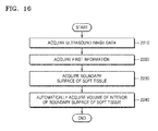
- an ultrasound diagnosis apparatus includes a data acquisition unit configured to acquire ultrasound image data regarding a object including a target bone which is to be diagnosed; and an image processing unit configured to acquire first information about at least one selected from a location of the target bone within an ultrasound image and a length of the target bone, based on volume data included in the ultrasound image data, acquire a boundary surface of a soft tissue that is adjacent to the target bone, based on the first information, and automatically acquire a volume of an interior of the boundary surface of the soft tissue.
- the image processing unit may three-dimensionally render at least one selected from the target bone and the boundary surface of the soft tissue, based on the volume data.
- the ultrasound diagnosis apparatus may further include a display unit configured to display the ultrasound image that is generated by the image processing unit.
- the display unit may display at least one selected from the ultrasound image that is based on a 3D-rendered target bone, a boundary surface of a 3D-rendered soft tissue, a cross section of the 3D-rendered target bone, a cross section of the boundary surface of the 3D-rendered soft tissue, and volume data; a length value of the target bone; and a volume value of the interior of the boundary surface of the soft tissue.
- the display unit may display an ultrasound image on which the target bone and the soft tissue are distinguished from each other.
- the display unit may display at least one selected from a 3D-rendered target bone, a boundary surface of the 3D-rendered soft tissue, a cross section of the 3D-rendered target bone, and a cross section of the boundary surface of the 3D-rendered soft tissue, with different patterns, different colors, and different degrees of transparency.
- the image processing unit may acquire a boundary surface of the soft tissue that surrounds at least a predetermined portion of the target bone.
- the image processing unit may acquire the boundary surface of the soft tissue such that a ratio of the length of the target bone to a length of the boundary surface of the soft tissue has a predetermined ratio in a lengthwise direction of the target bone.
- the predetermined ratio may include at least one selected from a pre-determined ratio and a ratio received from a user.
- the image processing unit may acquire the boundary surface of the soft tissue by using at least one selected from an active contour algorithm, segmentation using a cylindrical coordinate system transform, and slice-based segmentation.
- the image processing unit may extend a predetermined boundary surface from the target bone to the boundary surface of the soft tissue on the ultrasound image, acquire an extension parameter enabling the predetermined boundary surface to extend to the boundary surface of the soft tissue on the ultrasound image, a suppression parameter having an opposite sign to the extension parameter and preventing the predetermined boundary surface from exceeding the boundary surface of the soft tissue on the ultrasound image, and a smoothness parameter of which an absolute value decreases with a decrease in a change rate of an inclination of the predetermined boundary surface at a predetermined point, and acquire the boundary surface of the soft tissue, based on a predetermined function including the extension parameter, the suppression parameter, and the smoothness parameter.
- the image processing unit may transform the ultrasound image to a cylindrical coordinate system, extend a predetermined boundary surface from the target bone to the boundary surface of the soft tissue on the ultrasound image, acquire a variation parameter of which an absolute value decreases with an increase in a luminance change rate of a voxel in an ultrasound image obtained by the transformation to the cylindrical coordinate system, and a smoothness parameter of which an absolute value decreases with a decrease in a change rate of an inclination of the predetermined boundary surface, and acquire the boundary surface of the soft tissue, based on a predetermined function including the variation parameter and the smoothness parameter.
- the image processing unit may acquire a plurality of cross-section ultrasound images that are perpendicular to the target bone, acquire a boundary line of the soft tissue from each of the plurality of cross-section ultrasound images, and acquire the boundary surface of the soft tissue, based on the boundary line of the soft tissue acquired from each of the plurality of cross-section ultrasound images.
- the image processing unit may acquire binary ultrasound image data via thresholding based on the ultrasound image data, distinguish a plurality of segments within the binary ultrasound image data from one another via labeling, determine one of the plurality of segments as a target image, based on image properties of the target bone, and acquire the first information, based on the target image.
- the image processing unit may semi-automatically acquire the boundary surface of the soft tissue, based on at least one input received from a user.
- an ultrasound diagnosis method includes acquiring ultrasound image data regarding a object including a target bone which is to be diagnosed; acquiring first information about at least one selected from a location of the target bone within an ultrasound image and a length of the target bone, based on volume data included in the ultrasound image data; acquiring a boundary surface of a soft tissue that is adjacent to the target bone, based on the first information; and automatically acquiring a volume of an interior of the boundary surface of the soft tissue.
- the ultrasound diagnosis method may further include three-dimensionally rendering at least one selected from the target bone and the boundary surface of the soft tissue, based on the volume data.
- the ultrasound diagnosis method may further include displaying the ultrasound image that is based on the ultrasound image data.
- the displaying may include displaying at least one selected from: the ultrasound image that is based on a 3D-rendered target bone, a boundary surface of a 3D-rendered soft tissue, a cross section of the 3D-rendered target bone, a cross section of the boundary surface of the 3D-rendered soft tissue, and volume data; a length value of the target bone; and a volume value of the interior of the boundary surface of the soft tissue.
- the displaying may include displaying an ultrasound image on which the target bone and the soft tissue are distinguished from each other.
- the displaying may include displaying at least one selected from a 3D-rendered target bone, a boundary surface of the 3D-rendered soft tissue, a cross section of the 3D-rendered target bone, and a cross section of the boundary surface of the 3D-rendered soft tissue, with different patterns, different colors, and different degrees of transparency.
- the acquiring of the boundary surface of the soft tissue may include acquiring a boundary surface of the soft tissue that surrounds at least a predetermined portion of the target bone.
- the acquiring of the boundary surface of the soft tissue may include acquiring the boundary surface of the soft tissue such that a ratio of the length of the target bone to a length of the boundary surface of the soft tissue has a predetermined ratio in a lengthwise direction of the target bone.
- the predetermined ratio may include at least one selected from a pre-determined ratio and a ratio received from a user.
- the acquiring of the boundary surface of the soft tissue may use at least one selected from an active contour algorithm, segmentation using a cylindrical coordinate system transform, and slice-based segmentation.
- the acquiring of the boundary surface of the soft tissue may include, via the active contour algorithm: extending a predetermined boundary surface from the target bone to the boundary surface of the soft tissue on the ultrasound image; acquiring an extension parameter enabling the predetermined boundary surface to extend to the boundary surface of the soft tissue on the ultrasound image; acquiring a suppression parameter having an opposite sign to the extension parameter and preventing the predetermined boundary surface from exceeding the boundary surface of the soft tissue on the ultrasound image; acquiring a smoothness parameter of which an absolute value decreases with a decrease in a change rate of an inclination of the predetermined boundary surface at a predetermined point; and acquiring the boundary surface of the soft tissue, based on a predetermined function including the extension parameter, the suppression parameter, and the smoothness parameter.
- the acquiring of the boundary surface of the soft tissue may include, via the segmentation using the cylindrical coordinate system transform: transforming the ultrasound image to a cylindrical coordinate system; extending a predetermined boundary surface from the target bone to the boundary surface of the soft tissue on the ultrasound image; acquiring a variation parameter of which an absolute value decreases with an increase in a luminance change rate of a voxel in an ultrasound image obtained by the transformation to the cylindrical coordinate system; acquiring a smoothness parameter of which an absolute value decreases with a decrease in a change rate of an inclination of the predetermined boundary surface; and acquiring the boundary surface of the soft tissue, based on a predetermined function including the variation parameter and the smoothness parameter.
- the acquiring of the boundary surface of the soft tissue may include, via the slice-based segmentation: acquiring a plurality of cross-section ultrasound images that are perpendicular to the target bone; acquiring a boundary line of the soft tissue from each of the plurality of cross-section ultrasound images; and acquiring the boundary surface of the soft tissue, based on the boundary line of the soft tissue acquired from each of the plurality of cross-section ultrasound images.
- the acquiring of the first information may include acquiring binary ultrasound image data via thresholding based on the ultrasound image data; distinguishing a plurality of segments within the binary ultrasound image data from one another via labeling; determining one of the plurality of segments as a target image, based on image properties of the target bone; and acquiring the first information, based on the target image.
- the acquiring of the boundary surface of the soft tissue may include semi-automatically acquiring the boundary surface of the soft tissue, based on at least one input received from a user.
- a non-transitory computer-readable recording medium has recorded thereon a program for executing the ultrasound diagnosis method.
- an "ultrasound image” refers to an image of an object, which is obtained using ultrasound waves.
- an "object” may be a human, an animal, or a part of a human or animal.
- the object may be an organ (e.g., the liver, the heart, the womb, the brain, a breast, or the abdomen), a blood vessel, or a combination thereof.
- the object may be a phantom.
- the phantom means a material having a density, an effective atomic number, and a volume that are approximately the same as those of an organism.
- a "user” may be, but is not limited to, a medical expert, for example, a medical doctor, a nurse, a medical laboratory technologist, or a medical imaging expert, or a technician who repairs medical apparatuses.
- FIG. 1 is a diagram illustrating an ultrasound imaging apparatus 100 according to exemplary embodiments.
- FIG. 1 illustrates an overall configuration of an ultrasound diagnosis apparatus 100 according to exemplary embodiments.
- the ultrasound diagnosis apparatus 100 may include a probe 2, an ultrasound transmission/reception unit 10, an image processor 20, a communication module 30, a memory 40, an input device 50, and a control unit 60, where the components stated above may be connected to one another via buses 70.
- the ultrasound diagnosis apparatus 100 may be embodied not only as a cart type apparatus, but also as a portable apparatus.
- portable ultrasound diagnosis apparatuses may include a picture archiving and communication system (PACS) viewer, a smart phone, a laptop computer, a personal digital assistant (PDA), and a tablet personal computer (PC); however, the inventive concept is not limited thereto.
- PACS picture archiving and communication system
- PDA personal digital assistant
- PC tablet personal computer
- the probe 2 transmits ultrasound waves to an object 1 in response to a driving signal applied by the ultrasound transceiver 10 and receives echo signals reflected by the object 1.
- the probe 2 includes a plurality of transducers, and the plurality of transducers oscillate in response to electric signals and generate acoustic energy, that is, ultrasound waves.
- the probe 2 may be connected to a main body of the ultrasound diagnosis apparatus 100 by wire or wirelessly.
- the ultrasound diagnosis apparatus 100 may include a plurality of probes 2.
- a transmitter 11 supplies a driving signal to the probe 2.
- the transmitter 110 includes a pulse generator 17, a transmission delaying unit 18, and a pulser 19.
- the pulse generator 17 generates pulses for forming transmission ultrasound waves based on a predetermined pulse repetition frequency (PRF), and the transmission delaying unit 18 delays the pulses by delay times necessary for determining transmission directionality.
- the pulses which have been delayed correspond to a plurality of piezoelectric vibrators included in the probe 2, respectively.
- the pulser 19 applies a driving signal (or a driving pulse) to the probe 2 based on timing corresponding to each of the pulses which have been delayed.
- a receiver 12 generates ultrasound data by processing echo signals received from the probe 2.
- the receiver 120 may include an amplifier 13, an analog-to-digital converter (ADC) 14, a reception delaying unit 15, and a summing unit 16.
- the amplifier 13 amplifies echo signals in each channel, and the ADC 14 performs analog-to-digital conversion with respect to the amplified echo signals.
- the reception delaying unit 15 delays digital echo signals output by the ADC 1124 by delay times necessary for determining reception directionality, and the summing unit 16 generates ultrasound data by summing the echo signals processed by the reception delaying unit 15.
- the receiver 12 may not include the amplifier 13. In other words, if the sensitivity of the probe 2 or the capability of the ADC 14 to process bits is enhanced, the amplifier 13 may be omitted.
- the image processor 20 generates an ultrasound image by scan-converting ultrasound data generated by the ultrasound transceiver 10 and displays the ultrasound image.
- the ultrasound image may be not only a grayscale ultrasound image obtained by scanning an object in an amplitude (A) mode, a brightness (B) mode, and a motion (M) mode, but also a Doppler image showing a movement of an object via a Doppler effect.
- the Doppler image may be a blood flow Doppler image showing flow of blood (also referred to as a color Doppler image), a tissue Doppler image showing a movement of tissue, or a spectral Doppler image showing a moving speed of an object as a waveform.
- a B mode processor 22 extracts B mode components from ultrasound data and processes the B mode components.
- An image generator 24 may generate an ultrasound image indicating signal intensities as brightness based on the extracted B mode components 22.
- a Doppler processor 23 may extract Doppler components from ultrasound data, and the image generator 24 may generate a Doppler image indicating a movement of an object as colors or waveforms based on the extracted Doppler components.
- the image generator 24 may generate a three-dimensional (3D) ultrasound image via volume-rendering with respect to volume data and may also generate an elasticity image by imaging deformation of the object 1 due to pressure. Furthermore, the image generator 24 may display various pieces of additional information in an ultrasound image by using text and graphics. In addition, the generated ultrasound image may be stored in the memory 40.
- 3D three-dimensional
- a display 25 displays the generated ultrasound image.
- the display 25 may display not only an ultrasound image, but also various pieces of information processed by the ultrasound diagnosis apparatus 100 on a screen image via a graphical user interface (GUI).
- GUI graphical user interface
- the ultrasound apparatus 100 may include two or more displays 25 according to embodiments.
- the communication module 30 is connected to a network 3 by wire or wirelessly to communicate with an external device or a server.
- the communication module 30 may exchange data with a hospital server or another medical apparatus in a hospital, which is connected thereto via a PACS.
- the communication module 30 may perform data communication according to the digital imaging and communications in medicine (DICOM) standard.
- DICOM digital imaging and communications in medicine
- the communication module 30 may transmit or receive data related to diagnosis of an object, e.g., an ultrasound image, ultrasound data, and Doppler data of the object, via the network 3 and may also transmit or receive medical images captured by another medical apparatus, e.g., a computed tomography (CT) apparatus, a magnetic resonance imaging (MRI) apparatus, or an X-ray apparatus. Furthermore, the communication module 30 may receive information about a diagnosis history or medical treatment schedule of a patient from a server and utilizes the received information to diagnose the patient. Furthermore, the communication module 30 may perform data communication not only with a server or a medical apparatus in a hospital, but also with a portable terminal of a medical doctor or patient.
- CT computed tomography
- MRI magnetic resonance imaging
- the communication module 30 is connected to the network 3 by wire or wirelessly to exchange data with a server 35, a medical apparatus 34, or a portable terminal 36.
- the communication module 30 may include one or more components for communication with external devices.
- the communication module 1300 may include a local area communication module 31, a wired communication module 32, and a mobile communication module 33.
- the local area communication module 31 refers to a module for local area communication within a predetermined distance.
- Examples of local area communication techniques according to an embodiment may include, but are not limited to, wireless LAN, Wi-Fi, Bluetooth, ZigBee, Wi-Fi Direct (WFD), ultra wideband (UWB), infrared data association (IrDA), Bluetooth low energy (BLE), and near field communication (NFC).
- the wired communication module 32 refers to a module for communication using electric signals or optical signals. Examples of wired communication techniques according to an embodiment may include communication via a twisted pair cable, a coaxial cable, an optical fiber cable, and an Ethernet cable.
- the mobile communication module 33 transmits or receives wireless signals to or from at least one selected from a base station, an external terminal, and a server on a mobile communication network.
- the wireless signals may be voice call signals, video call signals, or various types of data for transmission and reception of text/multimedia messages.
- the memory 40 stores various data processed by the ultrasound apparatus 100.
- the memory 40 may store medical data related to diagnosis of an object, such as ultrasound data and an ultrasound image that are input or output, and may also store algorithms or programs which are to be executed in the ultrasound apparatus 100.
- the memory 40 may be any of various storage media, e.g., a flash memory, a hard disk drive, EEPROM, etc. Furthermore, the ultrasound apparatus 100 may utilize web storage or a cloud server that performs the storage function of the memory 40 online.
- the input device 50 refers to a means via which a user inputs data for controlling the ultrasound diagnosis apparatus 100.
- the input device 50 may include hardware components, such as a keypad, a mouse, a touch panel, a touch screen, and a jog switch.
- the input device 1600 may further include any of various other input units including an electrocardiogram (ECG) measuring module, a respiration measuring module, a voice recognition sensor, a gesture recognition sensor, a fingerprint recognition sensor, an iris recognition sensor, a depth sensor, a distance sensor, etc.
- ECG electrocardiogram
- the controller 60 may control all operations of the ultrasound diagnosis apparatus 100. In other words, the controller 60 may control operations among the probe 2, the ultrasound transceiver 10, the image processor 20, the communication module 30, the memory 40, and the input device 50 shown in FIG. 1 .
- All or some of the probe 2, the ultrasound transceiver 10, the image processor 20, the communication module 30, the memory 40, the input device 50, and the controller 60 may be implemented as software modules. However, embodiments of the present invention are not limited thereto, and some of the components stated above may be implemented as hardware modules. Also, at least one of the ultrasound transmission/reception unit 10, the image processor 20, and the communication module 30 may be included in the control unit 60; however, the inventive concept is not limited thereto.
- a marker may be set to indicate a predetermined position or set a diagnosis region in an ultrasound image including an object.
- the marker may be set at a portion that is to be observed in detail by the user to diagnose a disease or to check the health of a patient.
- the inventive concept provides an ultrasound diagnosis apparatus and an ultrasound image display method, which may change and output an ultrasound image to more accurately diagnose an object region in which the marker is set.
- FIG. 2 is a block diagram showing a configuration of a wireless probe 200 according to an embodiment of the present invention.
- the wireless probe 200 may include a plurality of transducers, and, according to embodiments, may include some or all of the components of the ultrasound transceiver 10 shown in FIG. 1 .
- the wireless probe 200 includes a transmitter 210, a transducer 220, and a receiver 230. Since descriptions thereof are given above with reference to FIG. 1 , detailed descriptions thereof will be omitted here.
- the wireless probe 200 may selectively include a reception delaying unit 233 and a summing unit 234.
- the wireless probe 200 may transmit ultrasound signals to the object 1, receive echo signals from the object 10, generate ultrasound data, and wirelessly transmit the ultrasound data to the ultrasound diagnosis apparatus 100 shown in FIG. 1 .
- An ultrasound diagnosis apparatus may be used in fetal biometric measurements. Fetal biometric measurements can be performed to estimate a gestational age of a fetus, evaluate the size of the fetus, and monitor growth of the fetus. Examples of the fetal biometric measurements include volume measurement of a predetermined part of an arm or leg of a fetus. A measured volume of a fetus may be used to estimate a nutrition state of the fetus. Thus, ultrasound diagnosis apparatuses and methods capable of efficiently measuring the volume of an object are required.
- An ultrasound diagnosis apparatus and method for measuring the volume of an object, and a computer-readable storage medium having the ultrasound diagnosis method recorded thereon, according to an embodiment of the present invention, will now be described in detail with reference to FIGS. 3-16 .
- FIG. 3 is a block diagram of an image processing apparatus according to an embodiment of the present invention.
- An ultrasound diagnosis apparatus 300 is any electronic apparatus capable of receiving, processing, and/or outputting an ultrasound image, and may be used for medical imaging apparatuses, such as, an ultrasound imaging apparatus, a computed tomography (CT) apparatus and a magnetic resonance imaging (MRI) apparatus.
- medical imaging apparatuses such as, an ultrasound imaging apparatus, a computed tomography (CT) apparatus and a magnetic resonance imaging (MRI) apparatus.
- CT computed tomography
- MRI magnetic resonance imaging
- the ultrasound diagnosis apparatus 300 may be included in a medical imaging apparatus.
- the ultrasound diagnosis apparatus 300 includes a data acquisition unit 310 and an image processing unit 320.
- the image processing unit 320 of FIG. 3 may correspond to the image processing unit 20 of FIG. 1 .
- the data acquisition unit 310 acquires ultrasound image data regarding an object including a target bone which is to be diagnosed.
- the image processing unit 320 acquires first information about at least one selected from a location of the target bone within an ultrasound image and a length of the target bone, based on volume data included in the ultrasound image data, acquires a boundary surface of a soft tissue that is adjacent to the target bone, based on the first information, and automatically acquires a volume of the interior of the boundary surface of the soft tissue.
- the image processing unit 320 may semi-automatically acquire the boundary surface of the soft tissue, based on at least one input received from a user.
- the ultrasound image data means data that is generated based on an ultrasound echo signal acquired via an ultrasound scan, or data that is used to image an ultrasound-scanned object to obtain an ultrasound image.
- the image processing unit 320 may three-dimensionally render at least one selected from the target bone and the boundary surface of the soft tissue, based on the volume data. Various methods may be used as the 3D rendering. In addition, the 3D rendering may be performed based on the boundary surface of the soft tissue acquired based on first information.
- the data acquisition device 310 may acquire the ultrasound image data regarding the object.
- the object is an animal body including a human body, or a part of the animal body.
- the object includes a target bone, and the target bone has a long tube shape.
- the object is a pregnant woman, and the target bone may be a long bone of a fetus, such as a thighbone.
- the object may include a soft tissue that is adjacent to the target bone.
- the soft tissue denotes a soft pat that surrounds a bone or a joint, or the tissue of the soft part.
- the soft tissue may include a film, a tendon, a ligament, fat, and a skin tissue that cover a bone.
- the ultrasound image data may be an ultrasound image of the target bone, 2D ultrasound image data used to image a section of the object, or volume data used to three-dimensionally image a 3D space within the object.
- the 2D ultrasound image data may be a plurality of pixel values, and the volume data may be a plurality of voxel values.
- a pixel value may be a luminance value of a pixel corresponding to the pixel value
- a voxel value may be a luminance value of a voxel corresponding to the voxel value.
- a point is used as a term that means a pixel or a voxel.
- the data acquisition unit 310 may acquire the ultrasound image data by scanning the object by using an ultrasound signal or the like, but embodiments of the present invention are not limited thereto.
- the data acquisition unit 310 may correspond to the ultrasound transmission/reception unit 10 of FIG. 1 , and may receive an ultrasound echo signal transmitted by the probe 2 and acquire the ultrasound image data by using the received ultrasound echo signal.
- the data acquisition unit 310 may receive scan information obtained by scanning the object by using a scanner outside the ultrasound diagnosis apparatus 300, for example, ultrasound data into which an ultrasound echo signal is converted, and acquire the ultrasound image data based on the scan information.
- the data acquisition unit 310 may receive the ultrasound image data from an external apparatus.
- the ultrasound diagnosis apparatus 300 may acquire the ultrasound image data according to any of various methods.
- the image processing unit 320 may acquire at least one selected from a location of the target bone, a length thereof, and a volume of the interior of the boundary surface of the soft tissue, by processing the ultrasound image data.
- the image processing unit 320 may acquire binary image data via thresholding based on the ultrasound image data, distinguish a plurality of segments within the binary ultrasound image data via labeling, determine one of the plurality of segments as a target image, based on image properties of the target bone, and measure at least one selected from a location and a length of the target bone, based on the target image.
- FIG. 4 is a block diagram of an image processing apparatus according to an embodiment of the present invention.
- an ultrasound diagnosis apparatus 400 includes a data acquisition unit 410, an image processing unit 420, and a display unit 430. Since the data acquisition unit 410 and the image processing unit 420 of FIG. 4 are respectively the same as the data acquisition unit 310 and the image processing unit 320 of FIG. 3 , redundant descriptions thereof are omitted here.
- the display unit 430 of FIG. 4 may correspond to the display unit 25 of FIG. 1 .
- the display unit 430 may display various ultrasound images that are generated by the image processing unit 420.
- the display unit 430 may also display at least one selected from: an ultrasound image that is based on a 3D-rendered target bone, a boundary surface of a 3D-rendered soft tissue, a cross section of the 3D-rendered target bone, a cross section of the boundary surface of the 3D-rendered soft tissue, and volume data; a length value of the target bone; and a volume value of the interior of the boundary surface of the soft tissue.
- the display unit 430 may also display an ultrasound image on which the target bone and the soft tissue are distinguished from each other.
- the display unit 430 may display at least one selected from the 3D-rendered target bone, the boundary surface of the 3D-rendered soft tissue, the cross section of the 3D-rendered target bone, and the cross section of the boundary surface of the 3D-rendered soft tissue, with different patterns, different colors, and different degrees of transparency.
- FIGS. 5A-7 and 17 illustrate images that may be displayed on the display unit 430, according to an embodiment of the present invention.
- the image processing unit 420 may three-dimensionally render at least one selected from the target bone and the boundary surface of the soft tissue, based on the volume data.
- the display unit 430 may display an image 510 including a 3D-rendered target bone 511, as shown in FIG. 5A .
- the display unit 430 may display an image 520 including both a 3D-rendered target bone 521 and a boundary surface 522 of a 3D-rendered soft tissue, as shown in FIG. 5B .
- the boundary surface 522 of the soft tissue may surround at least a predetermined portion of the 3D-rendered target bone 521.
- the boundary surface 522 of the soft tissue and the target bone 521 may have the same horizontal length as shown on the image 520 of FIG. 5B , but embodiments of the present invention are not limited thereto.
- the boundary surface 522 of the soft tissue may have a horizontal length that is greater than that of the 3D-rendered target bone 521.
- a boundary surface 532 of a soft tissue may have a horizontal length that is less than that of a target bone 531.
- the display unit 430 may display at least one selected from ultrasound images that are based on the volume data. For example, as shown in FIG. 5D , the display unit 430 may display an image 540 showing a target bone 541.
- the display 430 may display an image 610 including a boundary surface 614 of a 3D-rendered soft tissue.
- the boundary surface 614 of a 3D-rendered soft tissue may display locations 611, 612 and 613 of longitudinal sections.
- the display unit 430 may display ultrasound images 620, 630, and 640 obtained at the locations 611, 612 and 613 of the longitudinal sections.
- the display unit 430 may display the ultrasound image 620 obtained at the location 613 of the longitudinal section.
- a boundary line 621 of the soft tissue 621 may be displayed on the ultrasound image 620.
- the boundary line 621 of the soft tissue may be marked by a dotted line, a solid line, or the like.
- the display unit 430 may display the ultrasound image 630 obtained at the location 612 of the longitudinal section.
- a boundary line 631 of the soft tissue may be displayed on the ultrasound image 630.
- the boundary line 631 of the soft tissue may be marked by a dotted line, a solid line, or the like.
- the display unit 430 may display the ultrasound image 640 obtained at the location 611 of the longitudinal section.
- a boundary line 641 of the soft tissue may be displayed on the ultrasound image 640.
- the boundary line 641 of the soft tissue may be marked by a dotted line, a solid line, or the like. A user may easily ascertain the boundary surface of the soft tissue from the ultrasound images 620, 630 and 640 displayed on the display unit 430.
- the display unit 430 may display ultrasound images 650, 660, and 670 obtained at the locations 611, 612 and 613 of the longitudinal sections.
- the display unit 430 may display the interiors of boundary lines 651, 661 and 671 of a soft tissue with a particular color. A user may easily ascertain the boundary surface of the soft tissue from the ultrasound images 650, 660 and 670 displayed on the display unit 430.
- the display 430 may display a combination of the images shown in FIGS. 5A-6C on one screen image.
- the display unit 430 may display an image 760 including a boundary surface 764 of a 3D-rendered soft tissue.
- the display unit 430 may display the boundary surface 764 of the 3D-rendered soft tissue including locations 761, 762 and 763 of longitudinal sections.
- the display unit 430 may also display ultrasound images 710, 720, and 730 obtained at the locations 761, 762, and 763 of the longitudinal sections.
- the display unit 430 may also display an image 750 including a 3D-rendered target bone 751.
- the display unit 430 may also display an ultrasound image 740 including a target bone 741.
- the screen image illustrated in FIG. 7 is exemplary, and the display unit 430 may display various images in various combinations.
- the display 430 may display an ultrasound image 1740 including a target bone.
- the ultrasound diagnosis apparatus 400 may acquire a length and a location of the target bone.
- the display unit 430 may also display an indicator 1741 of the target bone, together with the ultrasound image 1740, based on the acquired length and location of the target bone.
- the indicator 1741 may be formed of both ends of the target bone and a dotted line that connects both ends of the target bone to each other. A user may easily ascertain the location and length of the target bone, based on the indicator 1741.
- the display unit 430 may also display an image 1750 including a boundary surface of a 3D-rendered soft tissue.
- the indicator 1741 displayed on the ultrasound image 1740 may also be displayed on the image 1750.
- the display unit 430 may also display a boundary surface 1750 of a 3D-rendered soft tissue including locations 1751, 1752, and 1753 of longitudinal sections.
- the locations 1751, 1752, and 1753 of longitudinal sections may be determined by a user.
- the locations 1751, 1752, and 1753 of longitudinal sections may be automatically determined by the ultrasound diagnosis apparatus 400.
- the ultrasound diagnosis apparatus 400 may determine both ends and a center point of the target bone, as the locations 1751, 1752, and 1753 of longitudinal sections.
- the ultrasound diagnosis apparatus 400 may previously store a predetermined ratio.
- the previously stored predetermined ratio may be 50%.
- the ultrasound diagnosis apparatus 400 may determine a center point of the target bone and points that are quarter lengths (25%) of the target bone from the center point of the target bone, as longitudinal section points.
- the display unit 430 may display ultrasound images obtained at the locations 1751, 1752, and 1753 of the longitudinal sections.
- the ultrasound image 1720 obtained at the location 1751 of the longitudinal section on the image 1750 may be displayed.
- the ultrasound image 1710 obtained at the location 1753 of the longitudinal section on the image 1750 may also be displayed.
- Boundaries 1711 and 1721 of a soft tissue may be displayed on the ultrasound images 1710 and 1720, respectively.
- the display unit 430 may display an image 1730 including a boundary surface of a 3D-rendered soft tissue.
- a length value 1733 of the target bone may be displayed on the image 1730.
- the length value 1733 of the target bone may be, for example, 36 mm.
- a length value of the soft tissue may also be displayed on the image 1730.
- the length value of the soft tissue may be 25 mm.
- Width values 1735 and 1736 of cross sections of the soft tissue may also be displayed on the image 1730.
- the width values 1735 and 1736 of the cross sections may be respectively 4.2 mm 2 and 6.5 mm 2 .
- a volume of the interior of the boundary of the soft tissue and an estimated weight based on the volume are indicated by reference numeral 1737, and may also be displayed on the image 1730.
- the volume of the interior of the boundary of the soft tissue may be 48.2 mm 3
- the estimated weight may be 2.53 kg.
- Reliabilities of the volume and the estimated weight may also be displayed on the image 1730, and may be respectively 96.3% and 98.7%.
- the display unit 430 may display a statistical graph 1760 showing an estimated weight versus a menstrual age.
- the statistical graph 1760 may show a current menstrual age 1761.
- a maximum graph 1762, an intermediate graph 1763, and a minimum graph 1764 of the estimated weight according to the menstrual age may also be displayed on the statistical graph 1760.
- a user may easily obtain desired information, based on information displayed on the display unit 430 as described above.
- a method of acquiring at least one selected from a location and a length of a target bone when ultrasound image data is 2D ultrasound image data will now be described in connection with the ultrasound diagnosis apparatus 400 of FIG. 4 , with reference to FIGS. 8A-9 .
- FIGS. 8A-8G illustrate 2D images obtained from 2D ultrasound image data, according to an embodiment of the present invention.
- FIG. 8A illustrates a 2D image obtained from 2D ultrasound image data.
- the 2D image of FIG. 8A is a B mode ultrasound image.
- the 2D image includes a target image which is an image of a target bone.
- a boundary of the target image is not distinct from the 2D image.
- the image processing unit 420 may process the 2D image as follows.
- the image processing unit 420 may acquire a preprocessed image by preprocessing the 2D image. For example, denoising based on a total variation (TV) algorithm may be performed as preprocessing.
- TV total variation
- FIG. 8B illustrates a pre-processed image obtained via denoising. Referring to FIG. 8B , noise is removed via denoising, and an edge of the target image is maintained.
- Denoising based on a TV algorithm is just an example, and the image processing unit 420 may remove noise from the 2D image via any of various other preprocessing methods in order to improve the quality of an image. However, the image processing unit 420 may skip preprocessing.
- the target image which is an image of the target bone
- the target image is thin and long, and a brightness value of the target image is higher than those of the other areas.
- the image processing unit 420 may perform a top-hat conversion on the preprocessed image.
- the image processing unit 420 may perform a top-hat conversion on a binary image.
- FIG. 8C illustrates a top-hat converted image
- contrast enhancing may be performed on the top-hat converted image, after a top-hat conversion is performed.
- CEh p h p - min max - min ⁇ 255
- h(p) indicates a luminance value of the point p in the top-hat converted image
- '255' varies according to a gray level that is applied to an image. When the gray level applied to an image is k, a value of (k-1) may be applied instead of '255' of Equation 2.
- FIG. 8D illustrates a contrast-enhanced image
- the image processing unit 420 may perform denoising, a top-hat conversion, and contrast enhancement on the 2D image.
- the image processing unit 420 may acquire a binary image to which an adaptive threshold has been applied, from the contrast-enhanced image.
- the binary image may be an image in which a point of the contrast-enhanced image having a luminance value that is greater than the adaptive threshold T is displayed with white, and the other points are displayed with black.
- a bone may be imaged with a bright color, and tissues other than the bone may be imaged with dark colors.
- an ultrasound image may be converted into a binary image capable of distinguishing the bone and the tissue other than the bone.
- the adaptive threshold may be acquired based on a mean and a standard deviation of luminance values in the contrast-enhanced image.
- FIG. 8E illustrates a binary image
- the binary image may include the target image, but may also include an image of another tissue having another shape.
- an image processing unit 420 of FIG. 4 may process the binary image as follows, in order to extract the target image.
- the image processing unit 420 may distinguish a plurality of segments within binary ultrasound image data from one another via labeling.
- Each of the plurality of segments is an area in which points having luminance values of 1 are collected.
- the plurality of segments are candidates of the target image.
- FIG. 8F illustrates a labeled binary image
- a plurality of segments in a binary image are labeled with different gray levels.
- FIG. 8F is only an example of labeling, and the binary image may be labeled according to various other methods.
- the plurality of segments may be each labeled with a number.
- the image processing unit 420 may determine one of the plurality of segments as the target image, based on image properties of the target bone. A segment having a largest number of image properties of the target bone from among the plurality of segments is determined as the target image, which is an image of the target bone.
- the image processing unit 420 may determine a segment having the greatest luminance value from among the plurality of segments as the target image. In detail, the image processing unit 420 may obtain a sum of luminance values of the points included in each of the plurality of segments, and determine a segment having the largest sum of luminance values as the target image.
- the image processing unit 420 may display all segments other than the segment determined as the target image, in black.
- FIG. 8G illustrates a binary image on which only the target image is displayed.
- the image processing unit 420 of FIG. 4 may measure a length of the target bone, based on the determined target image.
- FIG. 9 illustrates a method of measuring the length of the target bone, based on the target image, according to an embodiment of the present invention.
- the image processing unit 420 may acquire a measurement line 930 by skeletonizing the target image.
- the image processing unit 420 may measure the length of the target bone, based on a distance between a first point 910 and a second point 920, which are intersection points of the target image and the measurement line 930.
- FIG. 9 is only an example, and the image processing unit 420 may detect the first and second points 910 and 920, which are both end points in a long-axis direction of the target image, from the target image according to any of various other methods and measure the length of the target bone based on the distance between the both end points 910 and 920.
- ultrasound image data is 2D ultrasound image data
- ultrasound image data is volume data
- FIG. 10 illustrates volume data 1000 according to an embodiment of the present invention.
- the volume data 1000 includes a target image 1010, which is a 3D image of a target bone.
- a target image 1010 is a 3D image of a target bone.
- FIG. 10 clearly illustrates the target image 1010, but a boundary of a target image may not be distinct due to noise or the like in actual volume data.
- Pixel values are processed in 2D ultrasound image data, whereas voxel values are processed in volume data. Except for this difference, a method of processing 2D ultrasound image data may also be applied to volume data. Thus, portions of a volume data processing method that are the same as the method of processing 2D ultrasound image data will be described briefly, and portions of the volume data processing method that are applied to only volume data will be focused.
- the image processing unit 420 may acquire binary volume data from the volume data via thresholding.
- the above-described top-hat conversion, contrast enhancement, and the like may be performed before the binary volume data is acquired, and then the adaptive threshold may be applied.
- the binary volume data may include the target image, but may include an image of a tissue having a different shape from the target image.
- image processing for extracting the target image from the binary volume data may be performed as follows.
- the image processing unit 420 may perform labeling on the binary volume data.
- the binary volume data is divided into a plurality of segments via the labeling, and each of the plurality of segments is a 3D area where points having luminance values of 1 are collected.
- the plurality of segments are candidates of the target image.
- the image processing unit 420 may determine one of the plurality of segments as the target image. A segment having a largest number of image properties of the target bone from among the plurality of segments is determined as the target image. A location of the target image within an ultrasound image that is based on the volume data may correspond to a location of the target bone.
- Image properties of the target bone may include shape information and a luminance value.
- the image processing unit 420 may analyze the shape of each of the plurality of segments and acquire a plurality of residual segments from the plurality of segments based on the analyzed shapes. Next, the image processing unit 420 may determine one of the plurality of residual segments as the target image, based on the luminance value. The location of the target image within the ultrasound image based on the volume data may correspond to the location of the target bone.
- FIGS. 11A and 11B illustrate various shapes of target images 1110 and 1120 according to an embodiment of the present invention.
- the target images 1110 and 1120 each have a rectilineal tube shape or a curved tube shape.
- FIG. 11A illustrates a case where a target bone 1111 included in the target image 1110 has a long tube shape.
- FIG. 11B illustrates a case where the target image 1120 includes two target bones 1121 and 1122 and the two target bones 1121 and 1122 each have a long tube shape and are parallel to each other.
- the image processing unit 420 may perform principle component analysis (PCA) on each of the plurality of segments.
- PCA is a technique of analyzing a data collection, and is useful for ascertaining a distribution shape of data.
- PCA is an analysis technique of finding a direction of maximizing variance of data and contracting the data to thereby express information of the data for easier viewing of information of the data.
- data is linearly transformed to a new coordinate system, like the case where, when data is mapped to a single axis, an axis where variance of the data is the greatest is a first coordinate axis, and an axis where variance of the data is the next greatest is a second coordinate axis.
- the image processing unit 420 may obtain a direction and a size of a first principal component, those of a second principal component, and those of a third principal component, for each of the plurality of segments, via PCA.
- the size of the first principal component is relatively high, and the sizes of the second and third principal components are relatively low.
- the image processing unit 420 may analyze the shape of each of the plurality of segments, based on the sizes of the first, second, and third principal components.
- the image processing unit 420 may obtain a tube score for each of the plurality of segments and determine, as the plurality of residual segments, segments having tube cores that are greater than a critical value from among the plurality of segments. In other words, a segment having a tube core that is less than or equal to the critical value is excluded from a candidate of the target image.
- the critical value may be set empirically. For example, the critical value may be set to be 0.997.
- the image processing unit 420 acquires a plurality of residual segments from the plurality of segments, based on the analyzed shapes, and determines one of the plurality of residual segments as the target image, based on the luminance value.
- the image processing unit 420 may determine a segment having the greatest luminance value from among the plurality of residual segments as the target image. In detail, the image processing unit 420 may obtain a sum of luminance values of the points included in the plurality of residual segments and determine a segment having the greatest luminance value sum as the target image. A location of the target image within an ultrasound image based on the volume data may correspond to a location of the target bone.
- the image processing unit 420 excludes some of the plurality of segments from a candidate of the target image, by analyzing the shapes of the plurality of segments, before the target image is determined. To this end, a segment having a relatively large size may be prevented from being selected as the target image.
- the binary volume data may include images of a plurality of long bones.
- a long bone 1121 and another long bone 1122 exist within the volume data.
- the image processing unit 420 may acquire at least one selected from a location and a length of the long bone 1121, namely, the target bone.
- the image processing unit 420 may select an image of the other long bone 1122 from among the images of the plurality of long bones based on the length of the target bone, and also acquire at least one selected from locations and lengths of the other long bones.
- the image processing unit 420 may determine a longitudinal section of the target image, and measure the length of the target bone, based on the longitudinal section. To accurately measure the length of the target bone, the length of the target bone needs to be measured from the longitudinal section of the target bone.
- At least three points are needed to determine a specific plane in a 3D space, and should not be in a straight line.
- at least three points on the longitudinal section need to be determined.
- FIG. 12 illustrates a cross section of volume data 1000a according to an embodiment of the present invention.
- the volume data 1000a includes a segment that is determined as a target image 1010a.
- the image processing unit 420 acquires a mean point M1 corresponding to a mean coordinate of all points that belong to the target image 1010a.
- the image processing unit 420 may acquire both end points S1 and E1 that are farthest from a longitudinal section 1000b that passes through the mean point M1 from among points that belonging to the target image 1010a.
- the longitudinal section 1000b is a longitudinal section of the volume data 1000a that passes through the mean point M1.
- the image processing unit 420 sets spheres 1021 and 1022 of which centers are respectively the both end points S1 and E1.
- the image processing unit 420 acquires a first point S2 and a second point E2 respectively corresponding to mean coordinates of points that belong to both the target image 1010a and the spheres 1021 and 1022.
- Respective radii of the spheres 1021 and 1022 may be set such that points that belong to both the target image 1010a and the spheres 1021 and 1022 may adequately exist. For example, 1/3 of the distance between the both end points S1 and E1 may be set as the radius of each of the spheres 1021 and 1022.
- the image processing unit 420 acquires a point M2 to which a distance from the first point S2 is equal to a distance from the second point E2 from among the points belonging to the target image 1010a.
- the distance between the first point S2 and the point M2 is equal to that between the second point E2 and the point M2.
- a plurality of points to each of which a distance from the first point S2 is equal to a distance from the second point E2 exist among the points belonging to the target image 1010a.
- the image processing unit 420 may acquire one of the plurality of points as the point M2.
- the image processing unit 420 sets a sphere 1023 having the point M2 as its center.
- the image processing unit 420 acquires a third point M3 corresponding to a mean coordinate of points that belong to both the target image 1010a and the sphere 1023.
- the image processing unit 420 may determine a section passing through the first point S2, the second point E2, and the third point M3, as the longitudinal section of the target image 1010a.
- the image processing unit 420 may measure the length of the target bone, based on the distance between the first point S2 and the second point E2.
- the image processing unit 420 may acquire a center axis of the target bone, based on the distance between the first point S2 and the second point E2.
- FIG. 12 illustrates a method of determining the longitudinal section of the target image, but the longitudinal section of the target image may be determined according to various other methods.
- an ultrasound diagnosis apparatus and method capable of efficiently measuring at least one selected from a location and a length of a target bone may be provided.
- the image processing unit 420 may acquire a boundary surface of a soft tissue by using at least one selected from an active contour algorithm, segmentation using a cylindrical coordinate system transform, and slice-based segmentation.
- FIGS. 13A and 13E explain a process in which the ultrasound diagnosis apparatus 400 acquires a boundary surface of a soft tissue by using an active contour algorithm, according to an embodiment of the present invention.
- FIG. 13A illustrates an example of a 3D ultrasound image based on volume data including a boundary surface 1910 of a soft tissue and a target bone 1920.
- FIG. 13A clearly illustrates the boundary surface 1910 of the soft tissue and the target bone 1920.
- a boundary between the boundary surface 1910 of the soft tissue and the target bone 1920 is not distinct due to noise or the like. This is equally applied to FIGS. 13B and 13C , and thus will not be repeatedly described.
- a method of acquiring a boundary of a soft tissue from a 3D ultrasound image based on volume data will now be described.
- embodiments of the present invention are not limited thereto, and the boundary of the soft tissue may be directly acquired from the volume data.
- the image processing unit 420 may acquire the first information about at least one selected from the location of the target bone within the ultrasound image and the length of the target bone, based on the volume data included in the ultrasound image data, and acquire the boundary surface of the soft tissue that is adjacent to the target bone, based on the first information. According to an embodiment of the present invention, the image processing unit 420 may automatically acquire the boundary surface of the soft tissue, based on the ultrasound image data acquired by the data acquisition unit 410. The image processing unit 420 may use pre-stored data to automatically acquire the boundary surface of the soft tissue. Since the boundary surface of the soft tissue may be acquired without special manipulations, a user may more easily use the ultrasound diagnosis apparatus 400.
- the image processing unit 420 may semi-automatically acquire the boundary surface of the soft tissue, based on at least one input received from a user.
- the ultrasound diagnosis apparatus 400 may receive only an ancillary portion of a process of acquiring the boundary surface of the soft tissue from a user and acquire the boundary surface of the soft tissue.
- the ultrasound diagnosis apparatus 400 may receive an input including a predetermined ratio, a predetermined function, and a predetermined specific condition from the user.
- the ultrasound diagnosis apparatus 400 may receive a region of interest from the user.
- the ultrasound diagnosis apparatus 400 may correct information automatically acquired thereby, based on a user input.
- the ultrasound diagnosis apparatus 400 may acquire at least one selected from a location and a length of the target bone 1920 from the volume data.
- the boundary surface 1910 of the soft tissue may be acquired based on the acquired at least one selected from the location and the length of the target bone 1920.
- the ultrasound diagnosis apparatus 400 may acquire the boundary surface 1910 of the soft tissue, which covers a predetermined length of the target bone 1920.
- the image processing unit 420 may acquire the boundary surface of the soft tissue such that a ratio of the length of the target bone to the length of the boundary surface of the soft tissue has a predetermined ratio in a lengthwise direction of the target bone.
- the predetermined ratio may include at least one selected from a pre-determined ratio and a ratio received from a user.
- the ultrasound diagnosis apparatus 400 may receive a predetermined ratio from a user.
- the ultrasound diagnosis apparatus 400 may previously store a predetermined ratio.
- the predetermined ratio received from a user or the pre-stored predetermined ratio may be 50%.
- the ultrasound diagnosis apparatus 400 may acquire the boundary surface 1910 of the soft tissue, which covers 50% of the length of the target bone 1920 and of which a center coincides with the center point of the target bone 1920.
- the predetermined ratio received from a user or the pre-stored predetermined ratio may be 150%.
- the ultrasound diagnosis apparatus 400 may acquire the boundary surface 1910 of the soft tissue, which covers 150% of the length of the target bone 1920 and of which a center coincides with the center point of the target bone 1920.
- the image processing unit 420 may extend a predetermined boundary surface from the target bone to the boundary surface of the soft tissue on the ultrasound image, by using an active contour algorithm.
- the image processing unit 420 may acquire an extension parameter enabling the predetermined boundary surface to extend to the boundary surface of the soft tissue on the ultrasound image, a suppression parameter having a sign reverse to that of the extension parameter and suppressing the predetermined boundary surface from exceeding the boundary surface of the soft tissue, and a smoothness parameter having an absolute value that decreases with a decrease in a change rate of an inclination of the predetermined boundary surface at a predetermined point.
- the image processing unit 420 may acquire the boundary surface of the soft tissue, based on a predetermined function including the extension parameter, the suppression parameter, and the smoothness parameter.
- a function suitable for acquiring the boundary surface of the soft tissue may be used as the predetermined function.
- the image processing unit 420 may acquire the predetermined boundary surface as the boundary surface of the soft tissue.
- the predetermined specific condition may vary according to a definition of a function.
- the predetermined specific condition may include a case where values of the function are a maximum value, a minimum value, and an intermediate value.
- the predetermined function may be an absolute value of a sum of the extension parameter a, the suppression parameter b, and the smoothness parameter c.
- the image processing unit 420 may calculate a function value at the predetermined boundary surface.
- the image processing unit 420 may acquire, as the boundary surface of the soft tissue, a predetermined boundary surface when a function value satisfies a specific condition.
- the image processing unit 420 may acquire a predetermined boundary surface when a function value has a minimum value, as the boundary surface of the soft tissue.
- FIG. 13B illustrates an ultrasound image 1940 of a longitudinal section 1930 of FIG. 13A .
- An active contour algorithm may be performed on a 3D ultrasound image.
- an active contour algorithm is performed on a 2D ultrasound image.
- the longitudinal section 1930 of FIG. 13B is for convenience of explanation, and an actual longitudinal section may not be acquired.
- the ultrasound image 1940 may include a boundary 1941 of the target bone and a boundary surface 1942 of a soft tissue. Since the boundary surface 1942 of the soft tissue is still voxel data on the ultrasound image 1940, a user may visually recognize the boundary surface 1942 of the soft tissue. However, the ultrasound diagnosis apparatus 400 may not ascertain a location of the boundary surface 1942 of the soft tissue. In the related art, a user directly marks the boundary surface 1942 of the soft tissue such that the ultrasound diagnosis apparatus 400 may recognize a location of the boundary surface 1942 of the soft tissue. However, according to an embodiment of the present invention, the ultrasound diagnosis apparatus 400 may automatically acquire the location of the boundary surface 1942 of the soft tissue.
- the ultrasound diagnosis apparatus 400 acquires a location of the boundary 1941 of the target bone.
- the ultrasound diagnosis apparatus 400 may extend a predetermined boundary surface, based on the location of the boundary 1941 of the target bone.
- the predetermined boundary surface may be extended to the boundary surface 1942 of the soft tissue on the ultrasound image by the extension parameter.
- a size and a direction of the extension parameter 1943 may be shown as a vector.
- the direction of the extension parameter may be a direction of extension from the boundary 1941 of the target bone.
- the size of the extension parameter may depend on a luminance change rate of a voxel at each point of the predetermined boundary surface on the ultrasound image 1940. For example, the size of the extension parameter may increase with a decrease in a luminance change rate of a voxel at each point on the predetermined boundary surface in the direction of the extension parameter.
- extension parameter 1943 There may exist an extension parameter 1943 and a suppression parameter (not shown) that is opposite to the extension parameter 1943.
- the direction of the suppression parameter may be reverse to the direction of the extension parameter 1943.
- the size of the suppression parameter may increase with a decrease in a luminance change rate of a voxel at each point on the predetermined boundary surface in the direction of the suppression parameter. Since a luminance change rate of a voxel between the boundary 1941 of the target bone and the boundary surface 1942 of the soft tissue on the ultrasound image 1940 is not great, the size of the extension parameter may be greater than that of the suppression parameter.
- a sum of the values of the extension parameter and the suppression parameter may approximate to the value of the extension parameter.
- the predetermined boundary surface may be gradually extended toward the boundary surface 1942 of the soft tissue on the ultrasound image 1940 by the extension parameter.
- FIG. 13C illustrates an ultrasound image 1950 that is connected to FIG. 13B.
- FIG. 13C illustrates a case where a predetermined boundary surface 1953 is larger than a target bone 1951 and is smaller than a boundary surface 1952 of the soft tissue. Since a luminance change rate of a voxel at each point on the predetermined boundary surface 1953 is not large, an extension parameter 1954 may be greater than the suppression parameter. Thus, a sum of the extension parameter 1954 and the suppression parameter may approximate to the extension parameter 1954. Thus, the predetermined boundary surface 1953 may be further extended by the extension parameter 1954.
- FIG. 13D illustrates an ultrasound image 1960 that is connected to FIG. 13C .
- FIG. 13D illustrates a case where a predetermined boundary surface approximates to a boundary surface 1962 of the soft tissue.
- a luminance change rate of a voxel may increase.
- an extension parameter 1963 and a suppression parameter 1964 may equal to each other at one moment.
- the predetermined boundary surface may no longer extend nor reduced. In this case, the predetermined boundary surface may be acquired as the boundary surface of the soft tissue.
- FIG. 13E illustrates an ultrasound image 1970 for explaining a smoothness parameter in an active contour algorithm.
- the smoothness parameter has an absolute value that decreases with a decrease in a change rate of an inclination of a predetermined boundary surface 1973 at a predetermined point.
- the smoothness parameter may prevent the predetermined boundary surface 1973 from being greatly bent.
- a sum of the extension parameter and the suppression parameter may differ at each point on the predetermined boundary surface 1973. Due to the difference between the sums of the extension parameter and the suppression parameter, points on the predetermined boundary surface 1973 may extend at different ratios. As shown in FIG. 13E , the predetermined boundary surface 1973 may not be flat. Since a change rate of an inclination of the predetermined boundary surface 1973 of FIG. 13E at each point is high, the value of the smoothness parameter may increase.
- the smoothness parameter may be considered.
- the image processing unit 420 may acquire the boundary surface of the soft tissue, based on a predetermined function including an extension parameter, a suppression parameter, and a smoothness parameter.
- the predetermined function may be set using various methods in order to acquire an optimal boundary surface of a soft tissue.
- the image processing unit 420 may sum an extension parameter, a suppression parameter, and a smoothness parameter on a predetermined boundary surface and calculate an absolute value of the sum.
- the image processing unit 420 may acquire a predetermined boundary surface when the calculated absolute value has a minimum value, as the boundary surface of the soft tissue. In this case, unevenness as in the case of the predetermined boundary surface 1973 may be prevented in consideration of the smoothness parameter.
- FIGS. 14A-14D explain a process in which the ultrasound diagnosis apparatus 400 acquires a boundary surface of a soft tissue via segmentation using a cylindrical coordinate system transform, according to an embodiment of the present invention.
- the image processing unit 420 may acquire the boundary surface of the soft tissue via segmentation using a cylindrical coordinate system transform.
- the image processing unit 420 may transform the ultrasound image to a cylindrical coordinate system and extend the predetermined boundary surface from the target bone to the boundary surface of the soft tissue on the ultrasound image.
- the image processing unit 420 may acquire a variation parameter of which an absolute value decreases with an increase in the luminance change rate of a voxel in the ultrasound image transformed to the cylindrical coordinate system, and a smoothness parameter of which an absolute value decreases with a decrease in the change rate of an inclination of the predetermined boundary surface decreases.
- the image processing unit 420 may acquire the boundary surface of the soft tissue, based on a predetermined function including the variation parameter and the smoothness parameter.
- the image processing unit 420 may acquire a predetermined boundary surface when an absolute value of a sum of the extension parameter, the suppression parameter, and the smoothness parameter is at a minimum, as the boundary surface of the soft tissue.
- FIG. 14A clearly illustrates a boundary surface 2011 of a soft tissue.
- the boundary surface 2011 of the soft tissue is not distinct due to noise or the like. This is equally applied to FIG. 14B , and thus will not be further mentioned.
- a method of acquiring a boundary of a soft tissue from a 3D ultrasound image 2010 based on volume data will now be described.
- embodiments of the present invention are not limited thereto, and the boundary of the soft tissue may be directly acquired from the volume data.
- the ultrasound diagnosis apparatus 400 may transform the 3D ultrasound image 2010 from an orthogonal coordinate system (X, Y and Z axes) to a cylindrical coordinate system (r, ⁇ and Z axes).
- the 3D ultrasound image 2010, which is provided by the ultrasound diagnosis apparatus 400 may be displayed on the X, Y and Z axes.
- a central axis of the target bone may be aligned with the Z axis.
- the ultrasound diagnosis apparatus 400 may acquire the boundary surface 2011 of the soft tissue, which covers a predetermined length of the target bone.
- the ultrasound diagnosis apparatus 400 may receive a predetermined ratio from a user.
- the ultrasound diagnosis apparatus 400 may previously store a predetermined ratio.
- the predetermined ratio received from a user or the pre-stored predetermined ratio may be 50%.
- the image processing unit 420 may acquire a boundary surface 2011 of the soft tissue that covers 50% of the length of the target bone and of which a center coincides with the center point of the target bone according to the predetermined ratio.
- the predetermined ratio may be 150%.
- the image processing unit 420 may acquire a boundary surface 2011 of the soft tissue that covers 150% of the length of the target bone and of which a center coincides with the center point of the target bone.
- An arbitrary point 2012 within the 3D ultrasound image 2010 is Z 0 (2014) apart from an X-Y plane in a z-axis direction.
- the point 2012 is inclined at ⁇ 0 (2015) with respect to an X-Z plane.
- the point 2012 is ⁇ 0 (2013) apart from a Z axis.
- the point 2012 may be displayed at coordinates (r 0 , ⁇ 0 , Z 0 ) on the r, ⁇ and Z axes.
- Each point in the 3D ultrasound image 2010 displayed on the X, Y and Z axes (orthogonal coordinate system) may be displayed on the r, ⁇ , and Z axes (orthogonal coordinate system).
- FIG. 14B illustrates a 3D ultrasound image 2020 obtained by displaying the 3D ultrasound image 2010 of FIG. 14A in a cylindrical coordinate system.
- the 3D ultrasound image 2020 may include a boundary surface 2021 of a soft tissue. Since the boundary surface 2021 of the soft tissue is still pixel data on the 3D ultrasound image 2020, a user may visually recognize the boundary surface 2021 of the soft tissue. However, the ultrasound diagnosis apparatus 400 may not ascertain a location of the boundary surface 2012 of the soft tissue. According to an embodiment of the present invention, the ultrasound diagnosis apparatus 400 may automatically acquire the location of the boundary surface 2021 of the soft tissue.
- an area around a ⁇ -Z plane where the coordinate value of the r axis is 0 may be a surface 2022 of the target bone in FIG. 14B .
- the image processing unit 420 may extend the predetermined boundary surface from the surface 2022 of the target bone to the boundary surface 2021 of the soft tissue on the 3D ultrasound image 2020. Since the boundary surface 2021 of the soft tissue has a higher r-axis value than the surface 2022 of the target bone, an r-axis coordinate value of the entire predetermined boundary surface may increase.
- the image processing unit 420 may acquire a variation parameter of which an absolute value decreases with an increase in the luminance change rate of a voxel at each point of the predetermined boundary surface in the r-axis direction. For example, when the predetermined boundary surface is located near the boundary surface 2021 of the soft tissue, the luminance change rate of a voxel in the r-axis direction increases. Thus, the variation parameter may decrease near the boundary surface 2021.
- the image processing unit 420 may also acquire a smoothness parameter of which an absolute value decreases with a decrease in the change rate of an inclination of the predetermined boundary surface at a predetermined point. Since the smoothness parameter has already been described above with reference to FIG. 13E , a repeated description thereof will be omitted here.
- the image processing unit 420 may acquire the boundary surface 2021 of the soft tissue, based on a predetermined function including the variation parameter and the smoothness parameter.
- the image processing unit 420 may also acquire, as the boundary surface of the soft tissue, a predetermined boundary surface when the absolute value of a sum of the expansion parameter, the suppression parameter, and the smoothness parameter is minimum.
- the acquired boundary surface 2021 of the soft tissue may need to be transformed back to the orthogonal coordinate system.
- FIG. 14C illustrates a transform from a cylindrical coordinate system to an orthogonal coordinate system.
- coordinate transformation may be similar to an acquired boundary surface 2030 of a soft tissue surrounding the Z axis.
- FIG. 14D illustrates a boundary surface 2040 of a soft tissue that is acquired after the transform from the cylindrical coordinate system to the orthogonal coordinate system is completed.
- the ultrasound diagnosis apparatus 400 may acquire a volume of the interior of the boundary surface of the soft tissue, based on the acquired boundary surface 2040 of the soft tissue.
- FIGS. 15A and 15B explain a method of obtaining the boundary surface of the soft tissue by using slice-based segmentation, according to an embodiment of the present invention.
- the image processing unit 420 may acquire the boundary surface of the soft tissue via slice-based segmentation.
- the image processing unit 420 may acquire a plurality of cross-section ultrasound images that are perpendicular to the target bone.
- the image processing unit 420 may acquire a boundary line of the soft tissue from each of the plurality of cross-section ultrasound images.
- the image processing unit 420 may acquire the boundary surface of the soft tissue, based on the boundary line of the soft tissue acquired from each of the plurality of cross-section ultrasound images.
- the ultrasound diagnosis apparatus 400 may acquire the boundary surface of the soft tissue, based on the location and the length of the target bone, as described above with reference to FIGS. 10-12 .
- the ultrasound diagnosis apparatus 400 may acquire the boundary surface of the soft tissue that covers a predetermined length of the target bone.
- the ultrasound diagnosis apparatus 400 may acquire a boundary surface of the soft tissue that covers 50% of the length of the target bone and of which a center coincides with the center point of the target bone.
- the ultrasound diagnosis apparatus 400 may acquire a boundary surface of the soft tissue that covers 150% of the length of the target bone and of which a center coincides with the center point of the target bone.
- the ultrasound diagnosis apparatus 400 may acquire a plurality of longitudinal sections 2111-2115 from a 3D ultrasound image 2110.
- the number of longitudinal sections may be 5, but embodiments of the present invention are not limited thereto.
- the image processing unit 420 may acquire a 2D ultrasound image 2120 of the longitudinal section 2111.
- the image processing unit 420 may acquire a 2D ultrasound image 2130 of the longitudinal section 2112.
- the image processing unit 420 may acquire a 2D ultrasound image 2140 of the longitudinal section 2113.
- the image processing unit 420 may acquire a 2D ultrasound image 2150 of the longitudinal section 2114.
- the image processing unit 420 may acquire a 2D ultrasound image 2160 of the longitudinal section 2115.
- the image processing unit 420 may acquire respective boundary lines of the soft tissue from the 2D ultrasound images 2120, 2130, 2140, 2150, and 2160 according to the contour acquisition algorithm. For example, since the central axis of the target bone is acquired as described above with reference to FIGS. 10-12 , a point 2122 of the central axis of the target bone may be displayed on the 2D ultrasound image 2120. The image processing unit 420 may acquire a boundary line 2121 of the soft tissue on the basis of the point 2122 of the central axis of the target bone by using a contour acquisition algorithm. A 2D active contour algorithm may be used as the contour acquisition algorithm.
- boundary lines 2131, 2141, 2151, and 2161 of the soft tissue may be acquired from the ultrasound images 2130, 2140, 2150, and 2160, based on points 2132, 2142, 2152, and 2162 of the central axis of the target bone.
- FIG. 15B illustrates a 3D array of the acquired boundary lines 2121, 2131, 2141, 2151 and 2161 of the soft tissue.
- the boundary lines 2121, 2131, 2141, 2151 and 2161 of the soft tissue may be arranged such that the points 2122, 2132, 2142, 2152, and 2162 of the central axes of the target bone form a straight line. Intervals between the boundary lines 2121, 2131, 2141, 2151 and 2161 of the soft tissue are equal to intervals between the longitudinal sections 2111-2115 of the ultrasound image 2110 of FIG. 15A .
- the image processing unit 420 may acquire the boundary surface of the soft tissue, based on the boundary line of the soft tissue acquired from each of the plurality of cross-section ultrasound images.
- boundary lines 2171, 2172, 2173, 2174 and 2175 of the soft tissue respectively corresponding to points 2181, 2182, 2183, 2184 and 2185 of central axes of the target bone may be arranged such that the points 2181, 2182, 2183, 2184 and 2185 are aligned in a straight line.
- the image processing unit 420 may acquire lines that connect points on the boundary line 2172 of the soft tissue that are closest to the points on the boundary line 2171 of the soft tissue.
- the image processing unit 420 may also acquire a surface formed by the acquired lines, as a boundary surface of the soft tissue between the boundary lines 2171 and 2172 of the soft tissue.
- the image processing unit 420 may acquire boundary surfaces of the soft tissue between the boundary lines 2172 and 2175 of the soft tissue. Since from the boundary line 2171 of the soft tissue to the boundary line 2175 of the soft tissue may be filled with an arbitrary plane, a volume of the interior of a boundary surface of the soft tissue may be acquired.
- a boundary surface of a soft tissue may be acquired based on ultrasound data.
- the ultrasound diagnosis apparatus 400 may automatically acquire the volume of the interior of the boundary surface of the soft tissue.
- the ultrasound diagnosis apparatus 400 may estimate the weight of an object, based on the acquired volume.
- the ultrasound diagnosis apparatus 400 may use statistics to estimate the weight of the object.
- the ultrasound diagnosis apparatus 400 may have a predetermined correlation between the volume of the object and the weight thereof, based on statistics.
- the predetermined correlation is at least one selected from an equation, a statistical graph, and a statistical data value, and may be stored in the memory 40.
- the display unit 430 may display, as the predetermined correlation, at least one selected from the equation, the statistical graph, and the statistical data value.
- FIG. 16 is a flowchart of an ultrasound diagnosis method according to an embodiment of the present invention. Since the method of FIG. 16 is performed by the ultrasound diagnosis apparatus 400, descriptions thereof that are the same as those given above with reference to FIGS. 3-15B will be omitted here.
- the data acquisition unit 410 may acquire the ultrasound image data, in operation 2210.
- the image processing unit 420 may acquire the first information.
- the image processing unit 420 may acquire the boundary surface of the soft tissue.
- the image processing unit 420 may automatically acquire the volume of the interior of the boundary surface of the soft tissue.
- the data acquisition unit 410 may acquire the ultrasound image data regarding the object including the target bone which is to be diagnosed.
- the image processing unit 420 may acquire the first information about at least one selected from the location of the target bone within the ultrasound image and the length of the target bone, based on the volume data included in the ultrasound image data.
- the image processing unit 420 may acquire the boundary surface of the soft tissue that is adjacent to the target bone, based on the first information.
- the image processing unit 420 may acquire the volume of the interior of the boundary surface of the soft tissue.
- the boundary surface of the soft tissue may surround at least a predetermined portion of the target bone.
- the image processing unit 420 may further perform an operation of three-dimensionally rendering at least one selected from the target bone and the boundary surface of the soft tissue, based on the volume data.
- the display unit 430 may perform an operation of displaying an ultrasound image that is based on the ultrasound image data.
- the display unit 430 may perform an operation of displaying at least one selected from: an ultrasound image that is based on a 3D-rendered target bone, a boundary surface of a 3D-rendered soft tissue, a cross section of the 3D-rendered target bone, a cross section of the boundary surface of the 3D-rendered soft tissue, and volume data; a length value of the target bone; and a volume value of the interior of the boundary surface of the soft tissue.
- the display unit 430 may also perform an operation of displaying an ultrasound image on which the target bone and the soft tissue are distinguished from each other.
- the display unit 430 may perform an operation of displaying at least one selected from the 3D-rendered target bone, the boundary surface of the 3D-rendered soft tissue, the cross section of the 3D-rendered target bone, and the cross section of the boundary surface of the 3D-rendered soft tissue, with different patterns, different colors, and different degrees of transparency.
- the image processing unit 420 may also perform an operation of acquiring the boundary surface of the soft tissue that surrounds at least a predetermined portion of the target bone.
- the operation of acquiring the boundary surface of the soft tissue may include an operation of acquiring the boundary surface of the soft tissue such that a ratio of the length of the target bone to the length of the boundary surface of the soft tissue has a predetermined ratio in a lengthwise direction of the target bone.
- the predetermined ratio may include at least one selected from a pre-determined ratio and a ratio received from a user.
- the image processing unit 420 may acquire a boundary surface of a soft tissue by using at least one selected from an active contour algorithm, segmentation using a cylindrical coordinate system transform, and slice-based segmentation.
- the image processing unit 420 may acquire the boundary surface of the soft tissue by using an active contour algorithm. For example, the image processing unit 420 may perform an operation of extending a predetermined boundary surface from the target bone to the boundary surface of the soft tissue on the ultrasound image. The image processing unit 420 may perform an operation of acquiring an extension parameter enabling the predetermined boundary surface to extend from the target bone to the boundary surface of the soft tissue on the ultrasound image. The image processing unit 420 may perform an operation of acquiring a suppression parameter that has an opposite sign to the extension parameter and suppresses the predetermined boundary surface from exceeding the boundary surface of the soft tissue on the ultrasound image.
- the image processing unit 420 may perform an operation of acquiring a smoothness parameter of which an absolute value decreases with a decrease in the change rate of an inclination of the predetermined boundary surface at a predetermined point.
- the image processing unit 420 may perform an operation of acquiring the boundary surface of the soft tissue, based on a predetermined function including an extension parameter, a suppression parameter, and a smoothness parameter.
- the image processing unit 420 may acquire the boundary surface of the soft tissue via segmentation using the cylindrical coordinate system transform.
- the image processing unit 420 may perform an operation of transforming the volume data to the cylindrical coordinate system.
- the image processing unit 420 may perform an operation of extending a predetermined boundary surface from the target bone to the boundary surface of the soft tissue on the ultrasound image.
- the image processing unit 420 may perform an operation of acquiring a variation parameter of which an absolute value decreases with an increase in a change rate of volume data transformed to the cylindrical coordinate system.
- the image processing unit 420 may perform an operation of acquiring a smoothness parameter of which an absolute value decreases with a decrease in the change rate of an inclination of the predetermined boundary surface.
- the image processing unit 420 may perform an operation of acquiring the boundary surface of the soft tissue, based on a predetermined function including a variation parameter and a smoothness parameter.
- the image processing unit 420 may acquire the boundary surface of the soft tissue via slice-based segmentation.
- the image processing unit 420 may perform an operation of acquiring a plurality of cross-section ultrasound images that are perpendicular to the target bone.
- the image processing unit 420 may perform an operation of acquiring a boundary line of the soft tissue from each of the plurality of cross-section ultrasound images.
- the image processing unit 420 may perform an operation of acquiring the boundary surface of the soft tissue, based on the boundary line of the soft tissue acquired from each of the plurality of cross-section ultrasound images.
- the image processing unit 420 may perform an operation of acquiring the binary ultrasound image data via thresholding based on the ultrasound image data.
- the image processing unit 420 may perform an operation of distinguishing a plurality of segments within the binary ultrasound image data from one another via labeling.
- the image processing unit 420 may perform an operation of determining one of the plurality of segments as the target image, based on image properties of the target bone.
- the image processing unit 420 may perform an operation of acquiring the first information based on the target image.
- the operation of acquire the boundary surface of the soft tissue may include an operation of semi-automatically acquiring the boundary surface of the soft tissue, based on at least one input received from a user.
- a program for executing an ultrasound diagnosis method as described above may be recorded on a computer-readable storage medium.
- An ultrasound diagnosis apparatus may automatically acquire at least one selected from a location and a length of a target bone by automatically extracting ultrasound image data from a target image which is an image of the target bone.
- the ultrasound diagnosis apparatus may acquire a volume of a soft tissue that surrounds the target bone, based on the acquired at least one selected from the location and the length of the target bone.
- the embodiment of the present invention is efficient compared with the case where a user manually acquires the location and length of a target bone and the volume of a soft tissue around the target bone while viewing an image.
- manual measurement a measurement deviation occurs according to the skill of a user and a subjective determination of the user.
- manual measurement may require long time.
- the location and length of a target bone and the volume of a soft tissue around the target bone are automatically measured, and thus the accuracy of measurement may increase.
- automatic measurement may require short time.
- the ultrasound diagnosis apparatus may automatically extract the target image from the volume data and automatically determine a longitudinal section from the target image. If a user has to manually acquire a longitudinal section of the target bone, accuracy may not be guaranteed due to a deviation between users. If a user has to repeat a scan to acquire the longitudinal section, a repetitive stress injury (RSI) of the user may increase. Thus, according to an embodiment of the present invention, the accuracy of measurement may increase. In addition, the RSI of the user may decrease.
- RSI repetitive stress injury
- the above-described methods can be written as computer programs and can be implemented in general-use digital computers that execute the programs using a non-transitory computer readable recording medium.
- a structure of the data used in the above-described methods may be recorded in a non-transitory computer readable recording medium via several means.
- Examples of the non-transitory computer readable recording medium include magnetic storage media (e.g., ROM, RAM, USB, floppy disks, hard disks, etc.), optical recording media (e.g., CD-ROMs, or DVDs), etc.
Abstract
Description
- This application claims the benefit of Korean Patent Application No.
10-2014-0115694, filed on September 01, 2014 - One or more exemplary embodiments relate to an ultrasound diagnosis apparatus, an ultrasound diagnosis method performed by the ultrasound diagnosis apparatus, and a computer-readable storage medium having the ultrasound diagnosis method recorded thereon.
- More particularly, one or more exemplary embodiments relate to an ultrasound diagnosis apparatus capable of automatically measuring a physical numerical value of an object during an ultrasound diagnosis, an ultrasound diagnosis method performed by the ultrasound diagnosis apparatus, and a computer-readable storage medium having the ultrasound diagnosis method recorded thereon.
- Ultrasound diagnosis apparatuses transmit an ultrasound signal generated by a transducer of a probe to an object and receive information regarding an ultrasound echo signal reflected from the object, thereby obtaining an image of a part inside the object. In particular, ultrasound diagnosis apparatuses are used for medical purposes, such as observation of the inside of an object, detection of foreign substances inside the object, and diagnosis of damage thereof. Such ultrasound diagnosis apparatuses have various advantages, including stability, real-time display, and safety because there is no exposure to radiation, compared to X-ray apparatuses, and thus, the ultrasound diagnosis apparatuses are commonly used together with other image diagnosis apparatuses.
- Such ultrasound diagnosis apparatuses can be used in fetal biometric measurements. Fetal biometric measurements can be performed to estimate a gestational age of a fetus, evaluate the size of the fetus, and monitor growth of the fetus. Examples of the fetal biometric measurements include volume measurement of a predetermined part of an arm or leg of a fetus. The measured volume may be related to the weight of the fetus. The weight of the fetus can be used as information for use in diagnosing deformity and malnutrition of the fetus. In the related art, it is difficult to estimate the weight of a fetus based on three dimensional (3D) data. In addition, users use different methods to estimate the weight of a fetus based on 3D data. Thus, in the related art, the weight of a fetus is estimated based on two dimensional (2D) ultrasound image data. However, it has been recently reported that estimating the weight of a fetus based on 3D ultrasound image data is more accurate. Moreover, the weight of a fetus may be estimated by measuring the volume of an object of the fetus based on 3D ultrasound image data.
- Thus, ultrasound diagnosis apparatuses and methods capable of efficiently measuring the volume of an object are required.
- One or more exemplary embodiments include an ultrasound diagnosis apparatus and method capable of efficiently measuring the volume of an object.
- Additional aspects will be set forth in part in the description which follows and, in part, will be apparent from the description, or may be learned by practice of the presented embodiments.
- According to one or more embodiments of the present invention, an ultrasound diagnosis apparatus includes a data acquisition unit configured to acquire ultrasound image data regarding a object including a target bone which is to be diagnosed; and an image processing unit configured to acquire first information about at least one selected from a location of the target bone within an ultrasound image and a length of the target bone, based on volume data included in the ultrasound image data, acquire a boundary surface of a soft tissue that is adjacent to the target bone, based on the first information, and automatically acquire a volume of an interior of the boundary surface of the soft tissue.
- The image processing unit may three-dimensionally render at least one selected from the target bone and the boundary surface of the soft tissue, based on the volume data.
- The ultrasound diagnosis apparatus may further include a display unit configured to display the ultrasound image that is generated by the image processing unit.
- The display unit may display at least one selected from the ultrasound image that is based on a 3D-rendered target bone, a boundary surface of a 3D-rendered soft tissue, a cross section of the 3D-rendered target bone, a cross section of the boundary surface of the 3D-rendered soft tissue, and volume data; a length value of the target bone; and a volume value of the interior of the boundary surface of the soft tissue.
- The display unit may display an ultrasound image on which the target bone and the soft tissue are distinguished from each other.
- The display unit may display at least one selected from a 3D-rendered target bone, a boundary surface of the 3D-rendered soft tissue, a cross section of the 3D-rendered target bone, and a cross section of the boundary surface of the 3D-rendered soft tissue, with different patterns, different colors, and different degrees of transparency.
- The image processing unit may acquire a boundary surface of the soft tissue that surrounds at least a predetermined portion of the target bone.
- The image processing unit may acquire the boundary surface of the soft tissue such that a ratio of the length of the target bone to a length of the boundary surface of the soft tissue has a predetermined ratio in a lengthwise direction of the target bone.
- The predetermined ratio may include at least one selected from a pre-determined ratio and a ratio received from a user.
- The image processing unit may acquire the boundary surface of the soft tissue by using at least one selected from an active contour algorithm, segmentation using a cylindrical coordinate system transform, and slice-based segmentation.
- By using the active contour algorithm, the image processing unit may extend a predetermined boundary surface from the target bone to the boundary surface of the soft tissue on the ultrasound image, acquire an extension parameter enabling the predetermined boundary surface to extend to the boundary surface of the soft tissue on the ultrasound image, a suppression parameter having an opposite sign to the extension parameter and preventing the predetermined boundary surface from exceeding the boundary surface of the soft tissue on the ultrasound image, and a smoothness parameter of which an absolute value decreases with a decrease in a change rate of an inclination of the predetermined boundary surface at a predetermined point, and acquire the boundary surface of the soft tissue, based on a predetermined function including the extension parameter, the suppression parameter, and the smoothness parameter.
- Via the segmentation using the cylindrical coordinate system transform, the image processing unit may transform the ultrasound image to a cylindrical coordinate system, extend a predetermined boundary surface from the target bone to the boundary surface of the soft tissue on the ultrasound image, acquire a variation parameter of which an absolute value decreases with an increase in a luminance change rate of a voxel in an ultrasound image obtained by the transformation to the cylindrical coordinate system, and a smoothness parameter of which an absolute value decreases with a decrease in a change rate of an inclination of the predetermined boundary surface, and acquire the boundary surface of the soft tissue, based on a predetermined function including the variation parameter and the smoothness parameter.
- Via the slice-based segmentation, the image processing unit may acquire a plurality of cross-section ultrasound images that are perpendicular to the target bone, acquire a boundary line of the soft tissue from each of the plurality of cross-section ultrasound images, and acquire the boundary surface of the soft tissue, based on the boundary line of the soft tissue acquired from each of the plurality of cross-section ultrasound images.
- The image processing unit may acquire binary ultrasound image data via thresholding based on the ultrasound image data, distinguish a plurality of segments within the binary ultrasound image data from one another via labeling, determine one of the plurality of segments as a target image, based on image properties of the target bone, and acquire the first information, based on the target image.
- The image processing unit may semi-automatically acquire the boundary surface of the soft tissue, based on at least one input received from a user.
- According to one or more embodiments of the present invention, an ultrasound diagnosis method includes acquiring ultrasound image data regarding a object including a target bone which is to be diagnosed; acquiring first information about at least one selected from a location of the target bone within an ultrasound image and a length of the target bone, based on volume data included in the ultrasound image data; acquiring a boundary surface of a soft tissue that is adjacent to the target bone, based on the first information; and automatically acquiring a volume of an interior of the boundary surface of the soft tissue.
- The ultrasound diagnosis method may further include three-dimensionally rendering at least one selected from the target bone and the boundary surface of the soft tissue, based on the volume data.
- The ultrasound diagnosis method may further include displaying the ultrasound image that is based on the ultrasound image data.
- The displaying may include displaying at least one selected from: the ultrasound image that is based on a 3D-rendered target bone, a boundary surface of a 3D-rendered soft tissue, a cross section of the 3D-rendered target bone, a cross section of the boundary surface of the 3D-rendered soft tissue, and volume data; a length value of the target bone; and a volume value of the interior of the boundary surface of the soft tissue.
- The displaying may include displaying an ultrasound image on which the target bone and the soft tissue are distinguished from each other.
- The displaying may include displaying at least one selected from a 3D-rendered target bone, a boundary surface of the 3D-rendered soft tissue, a cross section of the 3D-rendered target bone, and a cross section of the boundary surface of the 3D-rendered soft tissue, with different patterns, different colors, and different degrees of transparency.
- The acquiring of the boundary surface of the soft tissue may include acquiring a boundary surface of the soft tissue that surrounds at least a predetermined portion of the target bone.
- The acquiring of the boundary surface of the soft tissue may include acquiring the boundary surface of the soft tissue such that a ratio of the length of the target bone to a length of the boundary surface of the soft tissue has a predetermined ratio in a lengthwise direction of the target bone.
- The predetermined ratio may include at least one selected from a pre-determined ratio and a ratio received from a user.
- The acquiring of the boundary surface of the soft tissue may use at least one selected from an active contour algorithm, segmentation using a cylindrical coordinate system transform, and slice-based segmentation.
- The acquiring of the boundary surface of the soft tissue may include, via the active contour algorithm: extending a predetermined boundary surface from the target bone to the boundary surface of the soft tissue on the ultrasound image; acquiring an extension parameter enabling the predetermined boundary surface to extend to the boundary surface of the soft tissue on the ultrasound image; acquiring a suppression parameter having an opposite sign to the extension parameter and preventing the predetermined boundary surface from exceeding the boundary surface of the soft tissue on the ultrasound image; acquiring a smoothness parameter of which an absolute value decreases with a decrease in a change rate of an inclination of the predetermined boundary surface at a predetermined point; and acquiring the boundary surface of the soft tissue, based on a predetermined function including the extension parameter, the suppression parameter, and the smoothness parameter.
- The acquiring of the boundary surface of the soft tissue may include, via the segmentation using the cylindrical coordinate system transform: transforming the ultrasound image to a cylindrical coordinate system; extending a predetermined boundary surface from the target bone to the boundary surface of the soft tissue on the ultrasound image; acquiring a variation parameter of which an absolute value decreases with an increase in a luminance change rate of a voxel in an ultrasound image obtained by the transformation to the cylindrical coordinate system; acquiring a smoothness parameter of which an absolute value decreases with a decrease in a change rate of an inclination of the predetermined boundary surface; and acquiring the boundary surface of the soft tissue, based on a predetermined function including the variation parameter and the smoothness parameter.
- The acquiring of the boundary surface of the soft tissue may include, via the slice-based segmentation: acquiring a plurality of cross-section ultrasound images that are perpendicular to the target bone; acquiring a boundary line of the soft tissue from each of the plurality of cross-section ultrasound images; and acquiring the boundary surface of the soft tissue, based on the boundary line of the soft tissue acquired from each of the plurality of cross-section ultrasound images.
- The acquiring of the first information may include acquiring binary ultrasound image data via thresholding based on the ultrasound image data; distinguishing a plurality of segments within the binary ultrasound image data from one another via labeling; determining one of the plurality of segments as a target image, based on image properties of the target bone; and acquiring the first information, based on the target image.
- The acquiring of the boundary surface of the soft tissue may include semi-automatically acquiring the boundary surface of the soft tissue, based on at least one input received from a user.
- According to one or more embodiments of the present invention, a non-transitory computer-readable recording medium has recorded thereon a program for executing the ultrasound diagnosis method.
- These and/or other aspects will become apparent and more readily appreciated from the following description of the exemplary embodiments, taken in conjunction with the accompanying drawings in which:
-
FIG. 1 is a block diagram of an ultrasound diagnosis apparatus according to an exemplary embodiment; -
FIG. 2 is a block diagram of a wireless probe according to an exemplary embodiment of the present invention; -
FIG. 3 is a block diagram of an image processing apparatus according to an exemplary embodiment of the present invention; -
FIG. 4 is a block diagram of an image processing apparatus according to an exemplary embodiment of the present invention; -
FIGS. 5A-5D illustrate images that may be displayed on a display unit, according to an exemplary embodiment of the present invention; -
FIGS. 6A-6C illustrate images that may be displayed on a display unit, according to an exemplary embodiment of the present invention; -
FIG. 7 illustrates images that may be displayed on a display unit, according to an exemplary embodiment of the present invention; -
FIGS. 8A-8G illustrate 2D images obtained from 2D ultrasound image data, according to an exemplary embodiment of the present invention; -
FIG. 9 illustrates a method of measuring the length of a target bone, based on a target image, according to an exemplary embodiment of the present invention; -
FIG. 10 illustrates volume data according to an exemplary embodiment of the present invention; -
FIGS. 11A and 11B illustrate various shapes of target images according to an exemplary embodiment of the present invention; -
FIG. 12 illustrates a cross section of volume data according to an exemplary embodiment of the present invention; -
FIGS. 13A-13E explain a process in which the ultrasound diagnosis apparatus acquires a boundary surface of a soft tissue by using an active contour algorithm, according to an exemplary embodiment of the present invention; -
FIGS. 14A-14D explain a process in which the ultrasound diagnosis apparatus acquires a boundary surface of a soft tissue via segmentation using a cylindrical coordinate system transform, according to an exemplary embodiment of the present invention; -
FIGS. 15A and 15B explain a method of obtaining the boundary surface of the soft tissue by using slice-based segmentation, according to an exemplary embodiment of the present invention; -
FIG. 16 is a flowchart of an ultrasound diagnosis method according to an exemplary embodiment of the present invention; and -
FIG. 17 illustrates images that may be displayed on a display unit, according to an exemplary embodiment of the present invention. - Reference will now be made in detail to embodiments, examples of which are illustrated in the accompanying drawings, wherein like reference numerals refer to the like elements throughout. In this regard, the present embodiments may have different forms and should not be construed as being limited to the descriptions set forth herein. Accordingly, the embodiments are merely described below, by referring to the figures, to explain aspects of the present description. As used herein, the term "and/or" includes any and all combinations of one or more of the associated listed items. Expressions such as "at least one of," when preceding a list of elements, modify the entire list of elements and do not modify the individual elements of the list.
- The terms used in this specification are those general terms currently widely used in the art in consideration of functions regarding the inventive concept, but the terms may vary according to the intention of those of ordinary skill in the art, precedents, or new technology in the art. Also, some terms may be arbitrarily selected by the applicant, and in this case, the meaning of the selected terms will be described in detail in the detailed description of the present specification. Thus, the terms used herein have to be defined based on the meaning of the terms together with the description throughout the specification.
- Throughout the specification, it will also be understood that when a component "includes" an element, unless there is another opposite description thereto, it should be understood that the component does not exclude another element and may further include another element. In addition, terms such as "... unit", "... module", or the like refer to units that perform at least one function or operation, and the units may be implemented as hardware or software or as a combination of hardware and software.
- Throughout the specification, an "ultrasound image" refers to an image of an object, which is obtained using ultrasound waves. Furthermore, an "object" may be a human, an animal, or a part of a human or animal. For example, the object may be an organ (e.g., the liver, the heart, the womb, the brain, a breast, or the abdomen), a blood vessel, or a combination thereof. Also, the object may be a phantom. The phantom means a material having a density, an effective atomic number, and a volume that are approximately the same as those of an organism.
- Throughout the specification, a "user" may be, but is not limited to, a medical expert, for example, a medical doctor, a nurse, a medical laboratory technologist, or a medical imaging expert, or a technician who repairs medical apparatuses.
- Hereinafter, exemplary embodiments will be described in detail with reference to the accompanying drawings.
-
FIG. 1 is a diagram illustrating an ultrasound imaging apparatus 100 according to exemplary embodiments. -
FIG. 1 illustrates an overall configuration of an ultrasound diagnosis apparatus 100 according to exemplary embodiments. - Referring to
FIG. 1 , the ultrasound diagnosis apparatus 100 may include a probe 2, an ultrasound transmission/reception unit 10, animage processor 20, acommunication module 30, a memory 40, an input device 50, and a control unit 60, where the components stated above may be connected to one another via buses 70. - The ultrasound diagnosis apparatus 100 may be embodied not only as a cart type apparatus, but also as a portable apparatus. Examples of portable ultrasound diagnosis apparatuses may include a picture archiving and communication system (PACS) viewer, a smart phone, a laptop computer, a personal digital assistant (PDA), and a tablet personal computer (PC); however, the inventive concept is not limited thereto.
- The probe 2 transmits ultrasound waves to an object 1 in response to a driving signal applied by the
ultrasound transceiver 10 and receives echo signals reflected by the object 1. The probe 2 includes a plurality of transducers, and the plurality of transducers oscillate in response to electric signals and generate acoustic energy, that is, ultrasound waves. Also, the probe 2 may be connected to a main body of the ultrasound diagnosis apparatus 100 by wire or wirelessly. According to exemplary embodiments, the ultrasound diagnosis apparatus 100 may include a plurality of probes 2. - A transmitter 11 supplies a driving signal to the probe 2. The transmitter 110 includes a pulse generator 17, a transmission delaying unit 18, and a pulser 19. The pulse generator 17 generates pulses for forming transmission ultrasound waves based on a predetermined pulse repetition frequency (PRF), and the transmission delaying unit 18 delays the pulses by delay times necessary for determining transmission directionality. The pulses which have been delayed correspond to a plurality of piezoelectric vibrators included in the probe 2, respectively. The pulser 19 applies a driving signal (or a driving pulse) to the probe 2 based on timing corresponding to each of the pulses which have been delayed.
- A receiver 12 generates ultrasound data by processing echo signals received from the probe 2. The receiver 120 may include an amplifier 13, an analog-to-digital converter (ADC) 14, a reception delaying unit 15, and a summing unit 16. The amplifier 13 amplifies echo signals in each channel, and the ADC 14 performs analog-to-digital conversion with respect to the amplified echo signals. The reception delaying unit 15 delays digital echo signals output by the
ADC 1124 by delay times necessary for determining reception directionality, and the summing unit 16 generates ultrasound data by summing the echo signals processed by the reception delaying unit 15. In some embodiments, the receiver 12 may not include the amplifier 13. In other words, if the sensitivity of the probe 2 or the capability of the ADC 14 to process bits is enhanced, the amplifier 13 may be omitted. - The
image processor 20 generates an ultrasound image by scan-converting ultrasound data generated by theultrasound transceiver 10 and displays the ultrasound image. The ultrasound image may be not only a grayscale ultrasound image obtained by scanning an object in an amplitude (A) mode, a brightness (B) mode, and a motion (M) mode, but also a Doppler image showing a movement of an object via a Doppler effect. The Doppler image may be a blood flow Doppler image showing flow of blood (also referred to as a color Doppler image), a tissue Doppler image showing a movement of tissue, or a spectral Doppler image showing a moving speed of an object as a waveform. - A B mode processor 22 extracts B mode components from ultrasound data and processes the B mode components. An image generator 24 may generate an ultrasound image indicating signal intensities as brightness based on the extracted B mode components 22.
- Similarly, a Doppler processor 23 may extract Doppler components from ultrasound data, and the image generator 24 may generate a Doppler image indicating a movement of an object as colors or waveforms based on the extracted Doppler components.
- According to an embodiment of the present invention, the image generator 24 may generate a three-dimensional (3D) ultrasound image via volume-rendering with respect to volume data and may also generate an elasticity image by imaging deformation of the object 1 due to pressure. Furthermore, the image generator 24 may display various pieces of additional information in an ultrasound image by using text and graphics. In addition, the generated ultrasound image may be stored in the memory 40.
- A display 25 displays the generated ultrasound image. The display 25 may display not only an ultrasound image, but also various pieces of information processed by the ultrasound diagnosis apparatus 100 on a screen image via a graphical user interface (GUI). In addition, the ultrasound apparatus 100 may include two or more displays 25 according to embodiments.
- The
communication module 30 is connected to a network 3 by wire or wirelessly to communicate with an external device or a server. Thecommunication module 30 may exchange data with a hospital server or another medical apparatus in a hospital, which is connected thereto via a PACS. Furthermore, thecommunication module 30 may perform data communication according to the digital imaging and communications in medicine (DICOM) standard. - The
communication module 30 may transmit or receive data related to diagnosis of an object, e.g., an ultrasound image, ultrasound data, and Doppler data of the object, via the network 3 and may also transmit or receive medical images captured by another medical apparatus, e.g., a computed tomography (CT) apparatus, a magnetic resonance imaging (MRI) apparatus, or an X-ray apparatus. Furthermore, thecommunication module 30 may receive information about a diagnosis history or medical treatment schedule of a patient from a server and utilizes the received information to diagnose the patient. Furthermore, thecommunication module 30 may perform data communication not only with a server or a medical apparatus in a hospital, but also with a portable terminal of a medical doctor or patient. - The
communication module 30 is connected to the network 3 by wire or wirelessly to exchange data with a server 35, amedical apparatus 34, or aportable terminal 36. Thecommunication module 30 may include one or more components for communication with external devices. For example, thecommunication module 1300 may include a local area communication module 31, awired communication module 32, and a mobile communication module 33. - The local area communication module 31 refers to a module for local area communication within a predetermined distance. Examples of local area communication techniques according to an embodiment may include, but are not limited to, wireless LAN, Wi-Fi, Bluetooth, ZigBee, Wi-Fi Direct (WFD), ultra wideband (UWB), infrared data association (IrDA), Bluetooth low energy (BLE), and near field communication (NFC).
- The
wired communication module 32 refers to a module for communication using electric signals or optical signals. Examples of wired communication techniques according to an embodiment may include communication via a twisted pair cable, a coaxial cable, an optical fiber cable, and an Ethernet cable. - The mobile communication module 33 transmits or receives wireless signals to or from at least one selected from a base station, an external terminal, and a server on a mobile communication network. The wireless signals may be voice call signals, video call signals, or various types of data for transmission and reception of text/multimedia messages.
- The memory 40 stores various data processed by the ultrasound apparatus 100. For example, the memory 40 may store medical data related to diagnosis of an object, such as ultrasound data and an ultrasound image that are input or output, and may also store algorithms or programs which are to be executed in the ultrasound apparatus 100.
- The memory 40 may be any of various storage media, e.g., a flash memory, a hard disk drive, EEPROM, etc. Furthermore, the ultrasound apparatus 100 may utilize web storage or a cloud server that performs the storage function of the memory 40 online.
- The input device 50 refers to a means via which a user inputs data for controlling the ultrasound diagnosis apparatus 100. The input device 50 may include hardware components, such as a keypad, a mouse, a touch panel, a touch screen, and a jog switch. However, embodiments are not limited thereto, and the
input device 1600 may further include any of various other input units including an electrocardiogram (ECG) measuring module, a respiration measuring module, a voice recognition sensor, a gesture recognition sensor, a fingerprint recognition sensor, an iris recognition sensor, a depth sensor, a distance sensor, etc. - The controller 60 may control all operations of the ultrasound diagnosis apparatus 100. In other words, the controller 60 may control operations among the probe 2, the
ultrasound transceiver 10, theimage processor 20, thecommunication module 30, the memory 40, and the input device 50 shown inFIG. 1 . - All or some of the probe 2, the
ultrasound transceiver 10, theimage processor 20, thecommunication module 30, the memory 40, the input device 50, and the controller 60 may be implemented as software modules. However, embodiments of the present invention are not limited thereto, and some of the components stated above may be implemented as hardware modules. Also, at least one of the ultrasound transmission/reception unit 10, theimage processor 20, and thecommunication module 30 may be included in the control unit 60; however, the inventive concept is not limited thereto. - A marker may be set to indicate a predetermined position or set a diagnosis region in an ultrasound image including an object.
- In detail, the marker may be set at a portion that is to be observed in detail by the user to diagnose a disease or to check the health of a patient. The inventive concept provides an ultrasound diagnosis apparatus and an ultrasound image display method, which may change and output an ultrasound image to more accurately diagnose an object region in which the marker is set.
-
FIG. 2 is a block diagram showing a configuration of a wireless probe 200 according to an embodiment of the present invention. - As described above with reference to
FIG. 1 , the wireless probe 200 may include a plurality of transducers, and, according to embodiments, may include some or all of the components of theultrasound transceiver 10 shown inFIG. 1 . - The wireless probe 200 according to the embodiment shown in
FIG. 2 includes a transmitter 210, a transducer 220, and a receiver 230. Since descriptions thereof are given above with reference toFIG. 1 , detailed descriptions thereof will be omitted here. In addition, according to embodiments, the wireless probe 200 may selectively include a reception delaying unit 233 and a summing unit 234. - The wireless probe 200 may transmit ultrasound signals to the object 1, receive echo signals from the
object 10, generate ultrasound data, and wirelessly transmit the ultrasound data to the ultrasound diagnosis apparatus 100 shown inFIG. 1 . - An ultrasound diagnosis apparatus may be used in fetal biometric measurements. Fetal biometric measurements can be performed to estimate a gestational age of a fetus, evaluate the size of the fetus, and monitor growth of the fetus. Examples of the fetal biometric measurements include volume measurement of a predetermined part of an arm or leg of a fetus. A measured volume of a fetus may be used to estimate a nutrition state of the fetus. Thus, ultrasound diagnosis apparatuses and methods capable of efficiently measuring the volume of an object are required.
- An ultrasound diagnosis apparatus and method for measuring the volume of an object, and a computer-readable storage medium having the ultrasound diagnosis method recorded thereon, according to an embodiment of the present invention, will now be described in detail with reference to
FIGS. 3-16 . -
FIG. 3 is a block diagram of an image processing apparatus according to an embodiment of the present invention. - An
ultrasound diagnosis apparatus 300 is any electronic apparatus capable of receiving, processing, and/or outputting an ultrasound image, and may be used for medical imaging apparatuses, such as, an ultrasound imaging apparatus, a computed tomography (CT) apparatus and a magnetic resonance imaging (MRI) apparatus. For example, theultrasound diagnosis apparatus 300 may be included in a medical imaging apparatus. - Referring to
FIG. 3 , theultrasound diagnosis apparatus 300 includes adata acquisition unit 310 and animage processing unit 320. Theimage processing unit 320 ofFIG. 3 may correspond to theimage processing unit 20 ofFIG. 1 . - The
data acquisition unit 310 acquires ultrasound image data regarding an object including a target bone which is to be diagnosed. Theimage processing unit 320 acquires first information about at least one selected from a location of the target bone within an ultrasound image and a length of the target bone, based on volume data included in the ultrasound image data, acquires a boundary surface of a soft tissue that is adjacent to the target bone, based on the first information, and automatically acquires a volume of the interior of the boundary surface of the soft tissue. Theimage processing unit 320 may semi-automatically acquire the boundary surface of the soft tissue, based on at least one input received from a user. The ultrasound image data means data that is generated based on an ultrasound echo signal acquired via an ultrasound scan, or data that is used to image an ultrasound-scanned object to obtain an ultrasound image. - The
image processing unit 320 may three-dimensionally render at least one selected from the target bone and the boundary surface of the soft tissue, based on the volume data. Various methods may be used as the 3D rendering. In addition, the 3D rendering may be performed based on the boundary surface of the soft tissue acquired based on first information. - The
data acquisition device 310 may acquire the ultrasound image data regarding the object. The object is an animal body including a human body, or a part of the animal body. The object includes a target bone, and the target bone has a long tube shape. For example, the object is a pregnant woman, and the target bone may be a long bone of a fetus, such as a thighbone. The object may include a soft tissue that is adjacent to the target bone. The soft tissue denotes a soft pat that surrounds a bone or a joint, or the tissue of the soft part. For example, the soft tissue may include a film, a tendon, a ligament, fat, and a skin tissue that cover a bone. The ultrasound image data may be an ultrasound image of the target bone, 2D ultrasound image data used to image a section of the object, or volume data used to three-dimensionally image a 3D space within the object. - The 2D ultrasound image data may be a plurality of pixel values, and the volume data may be a plurality of voxel values. A pixel value may be a luminance value of a pixel corresponding to the pixel value, and a voxel value may be a luminance value of a voxel corresponding to the voxel value. For convenience of explanation, hereinafter, a point is used as a term that means a pixel or a voxel.
- The
data acquisition unit 310 may acquire the ultrasound image data by scanning the object by using an ultrasound signal or the like, but embodiments of the present invention are not limited thereto. For example, thedata acquisition unit 310 may correspond to the ultrasound transmission/reception unit 10 ofFIG. 1 , and may receive an ultrasound echo signal transmitted by the probe 2 and acquire the ultrasound image data by using the received ultrasound echo signal. As another example, thedata acquisition unit 310 may receive scan information obtained by scanning the object by using a scanner outside theultrasound diagnosis apparatus 300, for example, ultrasound data into which an ultrasound echo signal is converted, and acquire the ultrasound image data based on the scan information. As another example, thedata acquisition unit 310 may receive the ultrasound image data from an external apparatus. However, embodiments of the present invention are not limited thereto, and theultrasound diagnosis apparatus 300 may acquire the ultrasound image data according to any of various methods. - The
image processing unit 320 may acquire at least one selected from a location of the target bone, a length thereof, and a volume of the interior of the boundary surface of the soft tissue, by processing the ultrasound image data. Theimage processing unit 320 may acquire binary image data via thresholding based on the ultrasound image data, distinguish a plurality of segments within the binary ultrasound image data via labeling, determine one of the plurality of segments as a target image, based on image properties of the target bone, and measure at least one selected from a location and a length of the target bone, based on the target image. -
FIG. 4 is a block diagram of an image processing apparatus according to an embodiment of the present invention. - Referring to
FIG. 4 , anultrasound diagnosis apparatus 400 includes adata acquisition unit 410, animage processing unit 420, and adisplay unit 430. Since thedata acquisition unit 410 and theimage processing unit 420 ofFIG. 4 are respectively the same as thedata acquisition unit 310 and theimage processing unit 320 ofFIG. 3 , redundant descriptions thereof are omitted here. - The
display unit 430 ofFIG. 4 may correspond to the display unit 25 ofFIG. 1 . Thedisplay unit 430 may display various ultrasound images that are generated by theimage processing unit 420. Thedisplay unit 430 may also display at least one selected from: an ultrasound image that is based on a 3D-rendered target bone, a boundary surface of a 3D-rendered soft tissue, a cross section of the 3D-rendered target bone, a cross section of the boundary surface of the 3D-rendered soft tissue, and volume data; a length value of the target bone; and a volume value of the interior of the boundary surface of the soft tissue. - The
display unit 430 may also display an ultrasound image on which the target bone and the soft tissue are distinguished from each other. For example, thedisplay unit 430 may display at least one selected from the 3D-rendered target bone, the boundary surface of the 3D-rendered soft tissue, the cross section of the 3D-rendered target bone, and the cross section of the boundary surface of the 3D-rendered soft tissue, with different patterns, different colors, and different degrees of transparency. -
FIGS. 5A-7 and17 illustrate images that may be displayed on thedisplay unit 430, according to an embodiment of the present invention. Theimage processing unit 420 may three-dimensionally render at least one selected from the target bone and the boundary surface of the soft tissue, based on the volume data. Thedisplay unit 430 may display animage 510 including a 3D-renderedtarget bone 511, as shown inFIG. 5A . Thedisplay unit 430 may display animage 520 including both a 3D-renderedtarget bone 521 and aboundary surface 522 of a 3D-rendered soft tissue, as shown inFIG. 5B . - The
boundary surface 522 of the soft tissue may surround at least a predetermined portion of the 3D-renderedtarget bone 521. Theboundary surface 522 of the soft tissue and thetarget bone 521 may have the same horizontal length as shown on theimage 520 ofFIG. 5B , but embodiments of the present invention are not limited thereto. Theboundary surface 522 of the soft tissue may have a horizontal length that is greater than that of the 3D-renderedtarget bone 521. For example, as shown inFIG. 5C , aboundary surface 532 of a soft tissue may have a horizontal length that is less than that of atarget bone 531. - The
display unit 430 may display at least one selected from ultrasound images that are based on the volume data. For example, as shown inFIG. 5D , thedisplay unit 430 may display animage 540 showing atarget bone 541. - Referring to
FIG. 6A , thedisplay 430 may display animage 610 including aboundary surface 614 of a 3D-rendered soft tissue. Theboundary surface 614 of a 3D-rendered soft tissue may displaylocations - Referring to
FIG. 6B , thedisplay unit 430 may displayultrasound images locations display unit 430 may display theultrasound image 620 obtained at thelocation 613 of the longitudinal section. Aboundary line 621 of thesoft tissue 621 may be displayed on theultrasound image 620. Theboundary line 621 of the soft tissue may be marked by a dotted line, a solid line, or the like. Thedisplay unit 430 may display theultrasound image 630 obtained at thelocation 612 of the longitudinal section. Aboundary line 631 of the soft tissue may be displayed on theultrasound image 630. Theboundary line 631 of the soft tissue may be marked by a dotted line, a solid line, or the like. Thedisplay unit 430 may display theultrasound image 640 obtained at thelocation 611 of the longitudinal section. Aboundary line 641 of the soft tissue may be displayed on theultrasound image 640. Theboundary line 641 of the soft tissue may be marked by a dotted line, a solid line, or the like. A user may easily ascertain the boundary surface of the soft tissue from theultrasound images display unit 430. - Referring to
FIG. 6C , thedisplay unit 430 may displayultrasound images locations FIG. 6B , thedisplay unit 430 may display the interiors ofboundary lines ultrasound images display unit 430. - Referring to
FIG. 7 , thedisplay 430 may display a combination of the images shown inFIGS. 5A-6C on one screen image. For example, thedisplay unit 430 may display animage 760 including aboundary surface 764 of a 3D-rendered soft tissue. Thedisplay unit 430 may display theboundary surface 764 of the 3D-rendered softtissue including locations display unit 430 may also displayultrasound images locations display unit 430 may also display animage 750 including a 3D-renderedtarget bone 751. Thedisplay unit 430 may also display anultrasound image 740 including atarget bone 741. The screen image illustrated inFIG. 7 is exemplary, and thedisplay unit 430 may display various images in various combinations. - Referring to
FIG. 17 , thedisplay 430 may display anultrasound image 1740 including a target bone. Theultrasound diagnosis apparatus 400 may acquire a length and a location of the target bone. Thedisplay unit 430 may also display anindicator 1741 of the target bone, together with theultrasound image 1740, based on the acquired length and location of the target bone. For example, theindicator 1741 may be formed of both ends of the target bone and a dotted line that connects both ends of the target bone to each other. A user may easily ascertain the location and length of the target bone, based on theindicator 1741. - The
display unit 430 may also display animage 1750 including a boundary surface of a 3D-rendered soft tissue. Theindicator 1741 displayed on theultrasound image 1740 may also be displayed on theimage 1750. Thedisplay unit 430 may also display aboundary surface 1750 of a 3D-rendered softtissue including locations locations locations ultrasound diagnosis apparatus 400. - For example, according to an embodiment of the present invention, the
ultrasound diagnosis apparatus 400 may determine both ends and a center point of the target bone, as thelocations ultrasound diagnosis apparatus 400 may previously store a predetermined ratio. For example, the previously stored predetermined ratio may be 50%. Theultrasound diagnosis apparatus 400 may determine a center point of the target bone and points that are quarter lengths (25%) of the target bone from the center point of the target bone, as longitudinal section points. - The
display unit 430 may display ultrasound images obtained at thelocations ultrasound image 1720 obtained at thelocation 1751 of the longitudinal section on theimage 1750 may be displayed. Theultrasound image 1710 obtained at thelocation 1753 of the longitudinal section on theimage 1750 may also be displayed.Boundaries ultrasound images - The
display unit 430 may display animage 1730 including a boundary surface of a 3D-rendered soft tissue. Alength value 1733 of the target bone may be displayed on theimage 1730. Thelength value 1733 of the target bone may be, for example, 36 mm. A length value of the soft tissue may also be displayed on theimage 1730. For example, the length value of the soft tissue may be 25 mm.Width values image 1730. For example, thewidth values reference numeral 1737, and may also be displayed on theimage 1730. For example, the volume of the interior of the boundary of the soft tissue may be 48.2 mm3, and the estimated weight may be 2.53 kg. Reliabilities of the volume and the estimated weight may also be displayed on theimage 1730, and may be respectively 96.3% and 98.7%. - The
display unit 430 may display astatistical graph 1760 showing an estimated weight versus a menstrual age. Thestatistical graph 1760 may show a currentmenstrual age 1761. Amaximum graph 1762, anintermediate graph 1763, and aminimum graph 1764 of the estimated weight according to the menstrual age may also be displayed on thestatistical graph 1760. A user may easily obtain desired information, based on information displayed on thedisplay unit 430 as described above. - A method of acquiring at least one selected from a location and a length of a target bone when ultrasound image data is 2D ultrasound image data will now be described in connection with the
ultrasound diagnosis apparatus 400 ofFIG. 4 , with reference toFIGS. 8A-9 . -
FIGS. 8A-8G illustrate 2D images obtained from 2D ultrasound image data, according to an embodiment of the present invention. -
FIG. 8A illustrates a 2D image obtained from 2D ultrasound image data. The 2D image ofFIG. 8A is a B mode ultrasound image. - Referring to
FIG. 8A , the 2D image includes a target image which is an image of a target bone. However, due to noise and an image of a tissue around the target bone, a boundary of the target image is not distinct from the 2D image. Thus, before performing thresholding, theimage processing unit 420 may process the 2D image as follows. - The
image processing unit 420 may acquire a preprocessed image by preprocessing the 2D image. For example, denoising based on a total variation (TV) algorithm may be performed as preprocessing. -
FIG. 8B illustrates a pre-processed image obtained via denoising. Referring toFIG. 8B , noise is removed via denoising, and an edge of the target image is maintained. - Denoising based on a TV algorithm is just an example, and the
image processing unit 420 may remove noise from the 2D image via any of various other preprocessing methods in order to improve the quality of an image. However, theimage processing unit 420 may skip preprocessing. - The target image, which is an image of the target bone, is thin and long, and a brightness value of the target image is higher than those of the other areas. Thus, to extract a thin, long, and bright area from the preprocessed image, the
image processing unit 420 may perform a top-hat conversion on the preprocessed image. When preprocessing is omitted, theimage processing unit 420 may perform a top-hat conversion on a binary image. - A top-hat conversion h may be expressed as Equation 1:

where f indicates an input image, namely, a preprocessed image, b indicates a structuring element, ° indicates an opening operation, and h indicates a top-hat converted image. -
FIG. 8C illustrates a top-hat converted image. - To more clearly distinguish the target image from the other areas by making the edge of the target image more distinct, contrast enhancing may be performed on the top-hat converted image, after a top-hat conversion is performed.
- For example, an image CEh(p) (where p indicates a point) obtained by applying contrast enhancing to a top-hat converted image of a 256 gray level may be acquired using Equation 2:

where h(p) indicates a luminance value of the point p in the top-hat converted image, and max and min respectively indicate a maximum luminance value and a minimum luminance value in the top-hat converted image. Since min is 0 or is approximate to 0, an adequately small value, such as, min=20, may be allocated. In Equation 2, '255' varies according to a gray level that is applied to an image. When the gray level applied to an image is k, a value of (k-1) may be applied instead of '255' of Equation 2. -
FIG. 8D illustrates a contrast-enhanced image. - As such, the
image processing unit 420 may perform denoising, a top-hat conversion, and contrast enhancement on the 2D image. - Next, the
image processing unit 420 may acquire a binary image to which an adaptive threshold has been applied, from the contrast-enhanced image. - For example, a binary image g(p) may be acquired from the contrast-enhanced image CEh(p) by using Equation 3:

where T indicates an adaptive threshold. In other words, the binary image may be an image in which a point of the contrast-enhanced image having a luminance value that is greater than the adaptive threshold T is displayed with white, and the other points are displayed with black. For example, as for ultrasound images, a bone may be imaged with a bright color, and tissues other than the bone may be imaged with dark colors. Thus, based on a difference between luminance values of a bone and a tissue other than the bone within an image, an ultrasound image may be converted into a binary image capable of distinguishing the bone and the tissue other than the bone. - The adaptive threshold may be acquired based on a mean and a standard deviation of luminance values in the contrast-enhanced image. For example, the adaptive threshold T may be acquired using Equation 4:

where m indicates a mean of luminance values in the contrast-enhanced image, s indicates a standard deviation of the luminance values, and a indicates a weight. -
FIG. 8E illustrates a binary image. - Referring to
FIG. 8E , the binary image may include the target image, but may also include an image of another tissue having another shape. - Thus, an
image processing unit 420 ofFIG. 4 may process the binary image as follows, in order to extract the target image. - The
image processing unit 420 may distinguish a plurality of segments within binary ultrasound image data from one another via labeling. Each of the plurality of segments is an area in which points having luminance values of 1 are collected. The plurality of segments are candidates of the target image. -
FIG. 8F illustrates a labeled binary image. - Referring to
FIG. 8F , a plurality of segments in a binary image are labeled with different gray levels. However,FIG. 8F is only an example of labeling, and the binary image may be labeled according to various other methods. For example, the plurality of segments may be each labeled with a number. - Next, the
image processing unit 420 may determine one of the plurality of segments as the target image, based on image properties of the target bone. A segment having a largest number of image properties of the target bone from among the plurality of segments is determined as the target image, which is an image of the target bone. - Since the target bone has a high reflectivity compared with neighboring tissues, the image of the target bone has a luminance value that is greater than those of the other areas. Thus, the
image processing unit 420 may determine a segment having the greatest luminance value from among the plurality of segments as the target image. In detail, theimage processing unit 420 may obtain a sum of luminance values of the points included in each of the plurality of segments, and determine a segment having the largest sum of luminance values as the target image. - A sum SL of luminance values of each segment may be calculated using Equation 5:

where L indicates an index of a segment and p indicates a point. - When the target image is determined, the
image processing unit 420 may display all segments other than the segment determined as the target image, in black. -
FIG. 8G illustrates a binary image on which only the target image is displayed. - The
image processing unit 420 ofFIG. 4 may measure a length of the target bone, based on the determined target image. -
FIG. 9 illustrates a method of measuring the length of the target bone, based on the target image, according to an embodiment of the present invention. - Referring to
FIG. 9 , theimage processing unit 420 may acquire ameasurement line 930 by skeletonizing the target image. Theimage processing unit 420 may measure the length of the target bone, based on a distance between afirst point 910 and asecond point 920, which are intersection points of the target image and themeasurement line 930. - However,
FIG. 9 is only an example, and theimage processing unit 420 may detect the first andsecond points end points - Until now, a case where ultrasound image data is 2D ultrasound image data has been described. Hereinafter, a case where ultrasound image data is volume data will be described in connection with the
ultrasound diagnosis apparatus 400 ofFIG. 4 . -
FIG. 10 illustratesvolume data 1000 according to an embodiment of the present invention. - Referring to
FIG. 10 , thevolume data 1000 includes atarget image 1010, which is a 3D image of a target bone. For convenience of illustration,FIG. 10 clearly illustrates thetarget image 1010, but a boundary of a target image may not be distinct due to noise or the like in actual volume data. - Pixel values are processed in 2D ultrasound image data, whereas voxel values are processed in volume data. Except for this difference, a method of processing 2D ultrasound image data may also be applied to volume data. Thus, portions of a volume data processing method that are the same as the method of processing 2D ultrasound image data will be described briefly, and portions of the volume data processing method that are applied to only volume data will be focused.
- The
image processing unit 420 may acquire binary volume data from the volume data via thresholding. The above-described top-hat conversion, contrast enhancement, and the like may be performed before the binary volume data is acquired, and then the adaptive threshold may be applied. - The binary volume data may include the target image, but may include an image of a tissue having a different shape from the target image. Thus, image processing for extracting the target image from the binary volume data may be performed as follows.
- The
image processing unit 420 may perform labeling on the binary volume data. The binary volume data is divided into a plurality of segments via the labeling, and each of the plurality of segments is a 3D area where points having luminance values of 1 are collected. The plurality of segments are candidates of the target image. - The
image processing unit 420 may determine one of the plurality of segments as the target image. A segment having a largest number of image properties of the target bone from among the plurality of segments is determined as the target image. A location of the target image within an ultrasound image that is based on the volume data may correspond to a location of the target bone. - Image properties of the target bone may include shape information and a luminance value.
- The
image processing unit 420 may analyze the shape of each of the plurality of segments and acquire a plurality of residual segments from the plurality of segments based on the analyzed shapes. Next, theimage processing unit 420 may determine one of the plurality of residual segments as the target image, based on the luminance value. The location of the target image within the ultrasound image based on the volume data may correspond to the location of the target bone. -
FIGS. 11A and 11B illustrate various shapes oftarget images - Referring to
FIGS. 11A and 11B , thetarget images FIG. 11A illustrates a case where atarget bone 1111 included in thetarget image 1110 has a long tube shape.FIG. 11B illustrates a case where thetarget image 1120 includes twotarget bones target bones - To analyze the shape of each of the plurality of segments, the
image processing unit 420 may perform principle component analysis (PCA) on each of the plurality of segments. PCA is a technique of analyzing a data collection, and is useful for ascertaining a distribution shape of data. PCA is an analysis technique of finding a direction of maximizing variance of data and contracting the data to thereby express information of the data for easier viewing of information of the data. In PCA, data is linearly transformed to a new coordinate system, like the case where, when data is mapped to a single axis, an axis where variance of the data is the greatest is a first coordinate axis, and an axis where variance of the data is the next greatest is a second coordinate axis. - The
image processing unit 420 may obtain a direction and a size of a first principal component, those of a second principal component, and those of a third principal component, for each of the plurality of segments, via PCA. In tube-shaped data, the size of the first principal component is relatively high, and the sizes of the second and third principal components are relatively low. Thus, theimage processing unit 420 may analyze the shape of each of the plurality of segments, based on the sizes of the first, second, and third principal components. - Using the sizes of first, second, and third principal components, a tube-score may be defined as follows:

where Ts indicates the tube score, λ 1 indicates the size of the first principal component, λ 2 indicates the size of the second principal component, and λ 3 indicates the size of the third principal component. - The
image processing unit 420 may obtain a tube score for each of the plurality of segments and determine, as the plurality of residual segments, segments having tube cores that are greater than a critical value from among the plurality of segments. In other words, a segment having a tube core that is less than or equal to the critical value is excluded from a candidate of the target image. The critical value may be set empirically. For example, the critical value may be set to be 0.997. - The
image processing unit 420 acquires a plurality of residual segments from the plurality of segments, based on the analyzed shapes, and determines one of the plurality of residual segments as the target image, based on the luminance value. - The
image processing unit 420 may determine a segment having the greatest luminance value from among the plurality of residual segments as the target image. In detail, theimage processing unit 420 may obtain a sum of luminance values of the points included in the plurality of residual segments and determine a segment having the greatest luminance value sum as the target image. A location of the target image within an ultrasound image based on the volume data may correspond to a location of the target bone. - The
image processing unit 420 excludes some of the plurality of segments from a candidate of the target image, by analyzing the shapes of the plurality of segments, before the target image is determined. To this end, a segment having a relatively large size may be prevented from being selected as the target image. - The binary volume data may include images of a plurality of long bones. For example, referring to
FIG. 11B , along bone 1121 and anotherlong bone 1122 exist within the volume data. According to the above-described method, theimage processing unit 420 may acquire at least one selected from a location and a length of thelong bone 1121, namely, the target bone. Next, theimage processing unit 420 may select an image of the otherlong bone 1122 from among the images of the plurality of long bones based on the length of the target bone, and also acquire at least one selected from locations and lengths of the other long bones. - Next, a method of measuring the length of the target bone based on the determined target image will be described.
- The
image processing unit 420 may determine a longitudinal section of the target image, and measure the length of the target bone, based on the longitudinal section. To accurately measure the length of the target bone, the length of the target bone needs to be measured from the longitudinal section of the target bone. - At least three points are needed to determine a specific plane in a 3D space, and should not be in a straight line. Thus, to determine the longitudinal section of the target image, at least three points on the longitudinal section need to be determined. Next, a method of determining three points on the longitudinal section of the target image will be described with reference to
FIG. 12 . -
FIG. 12 illustrates a cross section ofvolume data 1000a according to an embodiment of the present invention. - Referring to
FIG. 12 , thevolume data 1000a includes a segment that is determined as atarget image 1010a. Theimage processing unit 420 acquires a mean point M1 corresponding to a mean coordinate of all points that belong to thetarget image 1010a. In a 3D volume data, the mean coordinate may be calculated using Equation 7:
where Xavg, Yavg, and Zavg indicate mean coordinate values, n indicates the number of points, and Xn, Yn, and Zn indicate respective coordinate values of the points. - The
image processing unit 420 may acquire both end points S1 and E1 that are farthest from alongitudinal section 1000b that passes through the mean point M1 from among points that belonging to thetarget image 1010a. Thelongitudinal section 1000b is a longitudinal section of thevolume data 1000a that passes through the mean point M1. - The
image processing unit 420 setsspheres image processing unit 420 acquires a first point S2 and a second point E2 respectively corresponding to mean coordinates of points that belong to both thetarget image 1010a and thespheres spheres target image 1010a and thespheres spheres - The
image processing unit 420 acquires a point M2 to which a distance from the first point S2 is equal to a distance from the second point E2 from among the points belonging to thetarget image 1010a. In other words, the distance between the first point S2 and the point M2 is equal to that between the second point E2 and the point M2. A plurality of points to each of which a distance from the first point S2 is equal to a distance from the second point E2 exist among the points belonging to thetarget image 1010a. Theimage processing unit 420 may acquire one of the plurality of points as the point M2. - The
image processing unit 420 sets asphere 1023 having the point M2 as its center. Theimage processing unit 420 acquires a third point M3 corresponding to a mean coordinate of points that belong to both thetarget image 1010a and thesphere 1023. - The
image processing unit 420 may determine a section passing through the first point S2, the second point E2, and the third point M3, as the longitudinal section of thetarget image 1010a. Theimage processing unit 420 may measure the length of the target bone, based on the distance between the first point S2 and the second point E2. Theimage processing unit 420 may acquire a center axis of the target bone, based on the distance between the first point S2 and the second point E2. -
FIG. 12 illustrates a method of determining the longitudinal section of the target image, but the longitudinal section of the target image may be determined according to various other methods. - As such, according to an embodiment of the present invention, an ultrasound diagnosis apparatus and method capable of efficiently measuring at least one selected from a location and a length of a target bone may be provided.
- The
image processing unit 420 may acquire a boundary surface of a soft tissue by using at least one selected from an active contour algorithm, segmentation using a cylindrical coordinate system transform, and slice-based segmentation. -
FIGS. 13A and13E explain a process in which theultrasound diagnosis apparatus 400 acquires a boundary surface of a soft tissue by using an active contour algorithm, according to an embodiment of the present invention. -
FIG. 13A illustrates an example of a 3D ultrasound image based on volume data including aboundary surface 1910 of a soft tissue and atarget bone 1920. For convenience of illustration,FIG. 13A clearly illustrates theboundary surface 1910 of the soft tissue and thetarget bone 1920. However, in an actual ultrasound image, a boundary between theboundary surface 1910 of the soft tissue and thetarget bone 1920 is not distinct due to noise or the like. This is equally applied toFIGS. 13B and 13C , and thus will not be repeatedly described. For convenience of explanation, a method of acquiring a boundary of a soft tissue from a 3D ultrasound image based on volume data will now be described. However, embodiments of the present invention are not limited thereto, and the boundary of the soft tissue may be directly acquired from the volume data. - The
image processing unit 420 may acquire the first information about at least one selected from the location of the target bone within the ultrasound image and the length of the target bone, based on the volume data included in the ultrasound image data, and acquire the boundary surface of the soft tissue that is adjacent to the target bone, based on the first information. According to an embodiment of the present invention, theimage processing unit 420 may automatically acquire the boundary surface of the soft tissue, based on the ultrasound image data acquired by thedata acquisition unit 410. Theimage processing unit 420 may use pre-stored data to automatically acquire the boundary surface of the soft tissue. Since the boundary surface of the soft tissue may be acquired without special manipulations, a user may more easily use theultrasound diagnosis apparatus 400. - According to another embodiment of the present invention, the
image processing unit 420 may semi-automatically acquire the boundary surface of the soft tissue, based on at least one input received from a user. For example, theultrasound diagnosis apparatus 400 may receive only an ancillary portion of a process of acquiring the boundary surface of the soft tissue from a user and acquire the boundary surface of the soft tissue. Theultrasound diagnosis apparatus 400 may receive an input including a predetermined ratio, a predetermined function, and a predetermined specific condition from the user. Theultrasound diagnosis apparatus 400 may receive a region of interest from the user. Theultrasound diagnosis apparatus 400 may correct information automatically acquired thereby, based on a user input. - As described above with reference to
FIGS. 10-12 , theultrasound diagnosis apparatus 400 may acquire at least one selected from a location and a length of thetarget bone 1920 from the volume data. Theboundary surface 1910 of the soft tissue may be acquired based on the acquired at least one selected from the location and the length of thetarget bone 1920. Theultrasound diagnosis apparatus 400 may acquire theboundary surface 1910 of the soft tissue, which covers a predetermined length of thetarget bone 1920. Theimage processing unit 420 may acquire the boundary surface of the soft tissue such that a ratio of the length of the target bone to the length of the boundary surface of the soft tissue has a predetermined ratio in a lengthwise direction of the target bone. The predetermined ratio may include at least one selected from a pre-determined ratio and a ratio received from a user. - For example, according to an embodiment of the present invention, the
ultrasound diagnosis apparatus 400 may receive a predetermined ratio from a user. Alternatively, theultrasound diagnosis apparatus 400 may previously store a predetermined ratio. For example, the predetermined ratio received from a user or the pre-stored predetermined ratio may be 50%. Theultrasound diagnosis apparatus 400 may acquire theboundary surface 1910 of the soft tissue, which covers 50% of the length of thetarget bone 1920 and of which a center coincides with the center point of thetarget bone 1920. According to another embodiment of the present invention, the predetermined ratio received from a user or the pre-stored predetermined ratio may be 150%. Theultrasound diagnosis apparatus 400 may acquire theboundary surface 1910 of the soft tissue, which covers 150% of the length of thetarget bone 1920 and of which a center coincides with the center point of thetarget bone 1920. - For example, the
image processing unit 420 may extend a predetermined boundary surface from the target bone to the boundary surface of the soft tissue on the ultrasound image, by using an active contour algorithm. Theimage processing unit 420 may acquire an extension parameter enabling the predetermined boundary surface to extend to the boundary surface of the soft tissue on the ultrasound image, a suppression parameter having a sign reverse to that of the extension parameter and suppressing the predetermined boundary surface from exceeding the boundary surface of the soft tissue, and a smoothness parameter having an absolute value that decreases with a decrease in a change rate of an inclination of the predetermined boundary surface at a predetermined point. Theimage processing unit 420 may acquire the boundary surface of the soft tissue, based on a predetermined function including the extension parameter, the suppression parameter, and the smoothness parameter. A function suitable for acquiring the boundary surface of the soft tissue may be used as the predetermined function. When a value of a function that is based on parameters at the predetermined boundary surface satisfies a predetermined specific condition, theimage processing unit 420 may acquire the predetermined boundary surface as the boundary surface of the soft tissue. The predetermined specific condition may vary according to a definition of a function. For example, the predetermined specific condition may include a case where values of the function are a maximum value, a minimum value, and an intermediate value. - For example, a predetermined function including an extension parameter a, a suppression parameter b, and a smoothness parameter c may be expressed as follows:

- In other words, the predetermined function may be an absolute value of a sum of the extension parameter a, the suppression parameter b, and the smoothness parameter c. The
image processing unit 420 may calculate a function value at the predetermined boundary surface. Theimage processing unit 420 may acquire, as the boundary surface of the soft tissue, a predetermined boundary surface when a function value satisfies a specific condition. For example, theimage processing unit 420 may acquire a predetermined boundary surface when a function value has a minimum value, as the boundary surface of the soft tissue. -
FIG. 13B illustrates anultrasound image 1940 of alongitudinal section 1930 ofFIG. 13A . An active contour algorithm may be performed on a 3D ultrasound image. However, for convenience of explanation, inFIG. 13B , an active contour algorithm is performed on a 2D ultrasound image. In other words, thelongitudinal section 1930 ofFIG. 13B is for convenience of explanation, and an actual longitudinal section may not be acquired. - The
ultrasound image 1940 may include aboundary 1941 of the target bone and aboundary surface 1942 of a soft tissue. Since theboundary surface 1942 of the soft tissue is still voxel data on theultrasound image 1940, a user may visually recognize theboundary surface 1942 of the soft tissue. However, theultrasound diagnosis apparatus 400 may not ascertain a location of theboundary surface 1942 of the soft tissue. In the related art, a user directly marks theboundary surface 1942 of the soft tissue such that theultrasound diagnosis apparatus 400 may recognize a location of theboundary surface 1942 of the soft tissue. However, according to an embodiment of the present invention, theultrasound diagnosis apparatus 400 may automatically acquire the location of theboundary surface 1942 of the soft tissue. - Referring to
FIGS. 10-12 , theultrasound diagnosis apparatus 400 acquires a location of theboundary 1941 of the target bone. Theultrasound diagnosis apparatus 400 may extend a predetermined boundary surface, based on the location of theboundary 1941 of the target bone. The predetermined boundary surface may be extended to theboundary surface 1942 of the soft tissue on the ultrasound image by the extension parameter. A size and a direction of theextension parameter 1943 may be shown as a vector. The direction of the extension parameter may be a direction of extension from theboundary 1941 of the target bone. The size of the extension parameter may depend on a luminance change rate of a voxel at each point of the predetermined boundary surface on theultrasound image 1940. For example, the size of the extension parameter may increase with a decrease in a luminance change rate of a voxel at each point on the predetermined boundary surface in the direction of the extension parameter. - There may exist an
extension parameter 1943 and a suppression parameter (not shown) that is opposite to theextension parameter 1943. The direction of the suppression parameter may be reverse to the direction of theextension parameter 1943. The size of the suppression parameter may increase with a decrease in a luminance change rate of a voxel at each point on the predetermined boundary surface in the direction of the suppression parameter. Since a luminance change rate of a voxel between theboundary 1941 of the target bone and theboundary surface 1942 of the soft tissue on theultrasound image 1940 is not great, the size of the extension parameter may be greater than that of the suppression parameter. A sum of the values of the extension parameter and the suppression parameter may approximate to the value of the extension parameter. Thus, the predetermined boundary surface may be gradually extended toward theboundary surface 1942 of the soft tissue on theultrasound image 1940 by the extension parameter. -
FIG. 13C illustrates anultrasound image 1950 that is connected toFIG. 13B. FIG. 13C illustrates a case where apredetermined boundary surface 1953 is larger than atarget bone 1951 and is smaller than aboundary surface 1952 of the soft tissue. Since a luminance change rate of a voxel at each point on thepredetermined boundary surface 1953 is not large, anextension parameter 1954 may be greater than the suppression parameter. Thus, a sum of theextension parameter 1954 and the suppression parameter may approximate to theextension parameter 1954. Thus, thepredetermined boundary surface 1953 may be further extended by theextension parameter 1954. -
FIG. 13D illustrates anultrasound image 1960 that is connected toFIG. 13C .FIG. 13D illustrates a case where a predetermined boundary surface approximates to aboundary surface 1962 of the soft tissue. When the predetermined boundary surface approximates to theboundary surface 1962 of the soft tissue, a luminance change rate of a voxel may increase. Thus, anextension parameter 1963 and asuppression parameter 1964 may equal to each other at one moment. The predetermined boundary surface may no longer extend nor reduced. In this case, the predetermined boundary surface may be acquired as the boundary surface of the soft tissue. -
FIG. 13E illustrates anultrasound image 1970 for explaining a smoothness parameter in an active contour algorithm. - The smoothness parameter has an absolute value that decreases with a decrease in a change rate of an inclination of a
predetermined boundary surface 1973 at a predetermined point. The smoothness parameter may prevent thepredetermined boundary surface 1973 from being greatly bent. - A sum of the extension parameter and the suppression parameter may differ at each point on the
predetermined boundary surface 1973. Due to the difference between the sums of the extension parameter and the suppression parameter, points on thepredetermined boundary surface 1973 may extend at different ratios. As shown inFIG. 13E , thepredetermined boundary surface 1973 may not be flat. Since a change rate of an inclination of thepredetermined boundary surface 1973 ofFIG. 13E at each point is high, the value of the smoothness parameter may increase. - To address this problem, the smoothness parameter may be considered. In other words, the
image processing unit 420 may acquire the boundary surface of the soft tissue, based on a predetermined function including an extension parameter, a suppression parameter, and a smoothness parameter. The predetermined function may be set using various methods in order to acquire an optimal boundary surface of a soft tissue. For example, theimage processing unit 420 may sum an extension parameter, a suppression parameter, and a smoothness parameter on a predetermined boundary surface and calculate an absolute value of the sum. Theimage processing unit 420 may acquire a predetermined boundary surface when the calculated absolute value has a minimum value, as the boundary surface of the soft tissue. In this case, unevenness as in the case of thepredetermined boundary surface 1973 may be prevented in consideration of the smoothness parameter. -
FIGS. 14A-14D explain a process in which theultrasound diagnosis apparatus 400 acquires a boundary surface of a soft tissue via segmentation using a cylindrical coordinate system transform, according to an embodiment of the present invention. - The
image processing unit 420 may acquire the boundary surface of the soft tissue via segmentation using a cylindrical coordinate system transform. Theimage processing unit 420 may transform the ultrasound image to a cylindrical coordinate system and extend the predetermined boundary surface from the target bone to the boundary surface of the soft tissue on the ultrasound image. Theimage processing unit 420 may acquire a variation parameter of which an absolute value decreases with an increase in the luminance change rate of a voxel in the ultrasound image transformed to the cylindrical coordinate system, and a smoothness parameter of which an absolute value decreases with a decrease in the change rate of an inclination of the predetermined boundary surface decreases. Theimage processing unit 420 may acquire the boundary surface of the soft tissue, based on a predetermined function including the variation parameter and the smoothness parameter. Theimage processing unit 420 may acquire a predetermined boundary surface when an absolute value of a sum of the extension parameter, the suppression parameter, and the smoothness parameter is at a minimum, as the boundary surface of the soft tissue. - For convenience of illustration,
FIG. 14A clearly illustrates aboundary surface 2011 of a soft tissue. However, in an actual ultrasound image, theboundary surface 2011 of the soft tissue is not distinct due to noise or the like. This is equally applied toFIG. 14B , and thus will not be further mentioned. For convenience of explanation, a method of acquiring a boundary of a soft tissue from a3D ultrasound image 2010 based on volume data will now be described. However, embodiments of the present invention are not limited thereto, and the boundary of the soft tissue may be directly acquired from the volume data. - The
ultrasound diagnosis apparatus 400 may transform the3D ultrasound image 2010 from an orthogonal coordinate system (X, Y and Z axes) to a cylindrical coordinate system (r, θ and Z axes). For example, the3D ultrasound image 2010, which is provided by theultrasound diagnosis apparatus 400, may be displayed on the X, Y and Z axes. Based on the location of the target bone acquired as described above with reference toFIGS. 10-12 , a central axis of the target bone may be aligned with the Z axis. - The
ultrasound diagnosis apparatus 400 may acquire theboundary surface 2011 of the soft tissue, which covers a predetermined length of the target bone. For example, according to an embodiment of the present invention, theultrasound diagnosis apparatus 400 may receive a predetermined ratio from a user. Alternatively, theultrasound diagnosis apparatus 400 may previously store a predetermined ratio. For example, the predetermined ratio received from a user or the pre-stored predetermined ratio may be 50%. Theimage processing unit 420 may acquire aboundary surface 2011 of the soft tissue that covers 50% of the length of the target bone and of which a center coincides with the center point of the target bone according to the predetermined ratio. According to another embodiment of the present invention, the predetermined ratio may be 150%. Theimage processing unit 420 may acquire aboundary surface 2011 of the soft tissue that covers 150% of the length of the target bone and of which a center coincides with the center point of the target bone. - An
arbitrary point 2012 within the3D ultrasound image 2010 is Z0 (2014) apart from an X-Y plane in a z-axis direction. Thepoint 2012 is inclined at θ0 (2015) with respect to an X-Z plane. Thepoint 2012 is θ0 (2013) apart from a Z axis. Thepoint 2012 may be displayed at coordinates (r0, θ0, Z0) on the r, θ and Z axes. Each point in the3D ultrasound image 2010 displayed on the X, Y and Z axes (orthogonal coordinate system) may be displayed on the r, θ, and Z axes (orthogonal coordinate system). -
FIG. 14B illustrates a3D ultrasound image 2020 obtained by displaying the3D ultrasound image 2010 ofFIG. 14A in a cylindrical coordinate system. - In
FIG. 14B , points of the3D ultrasound image 2020 are displayed on the r, θ and Z axes. The3D ultrasound image 2020 may include aboundary surface 2021 of a soft tissue. Since theboundary surface 2021 of the soft tissue is still pixel data on the3D ultrasound image 2020, a user may visually recognize theboundary surface 2021 of the soft tissue. However, theultrasound diagnosis apparatus 400 may not ascertain a location of theboundary surface 2012 of the soft tissue. According to an embodiment of the present invention, theultrasound diagnosis apparatus 400 may automatically acquire the location of theboundary surface 2021 of the soft tissue. - Since the central axis of the target bone coincides with the Z axis as described above with reference to
FIG. 14A , an area around a θ-Z plane where the coordinate value of the r axis is 0 may be asurface 2022 of the target bone inFIG. 14B . Theimage processing unit 420 may extend the predetermined boundary surface from thesurface 2022 of the target bone to theboundary surface 2021 of the soft tissue on the3D ultrasound image 2020. Since theboundary surface 2021 of the soft tissue has a higher r-axis value than thesurface 2022 of the target bone, an r-axis coordinate value of the entire predetermined boundary surface may increase. - The
image processing unit 420 may acquire a variation parameter of which an absolute value decreases with an increase in the luminance change rate of a voxel at each point of the predetermined boundary surface in the r-axis direction. For example, when the predetermined boundary surface is located near theboundary surface 2021 of the soft tissue, the luminance change rate of a voxel in the r-axis direction increases. Thus, the variation parameter may decrease near theboundary surface 2021. - The
image processing unit 420 may also acquire a smoothness parameter of which an absolute value decreases with a decrease in the change rate of an inclination of the predetermined boundary surface at a predetermined point. Since the smoothness parameter has already been described above with reference toFIG. 13E , a repeated description thereof will be omitted here. - The
image processing unit 420 may acquire theboundary surface 2021 of the soft tissue, based on a predetermined function including the variation parameter and the smoothness parameter. Theimage processing unit 420 may also acquire, as the boundary surface of the soft tissue, a predetermined boundary surface when the absolute value of a sum of the expansion parameter, the suppression parameter, and the smoothness parameter is minimum. However, it may be difficult to measure a volume of the inside of the acquiredboundary surface 2021 of the soft tissue from the3D ultrasound image 2020 displayed in the cylindrical coordinate system. Thus, the acquiredboundary surface 2021 of the soft tissue may need to be transformed back to the orthogonal coordinate system. -
FIG. 14C illustrates a transform from a cylindrical coordinate system to an orthogonal coordinate system. In other words, coordinate transformation may be similar to an acquiredboundary surface 2030 of a soft tissue surrounding the Z axis. -
FIG. 14D illustrates aboundary surface 2040 of a soft tissue that is acquired after the transform from the cylindrical coordinate system to the orthogonal coordinate system is completed. Theultrasound diagnosis apparatus 400 may acquire a volume of the interior of the boundary surface of the soft tissue, based on the acquiredboundary surface 2040 of the soft tissue. -
FIGS. 15A and 15B explain a method of obtaining the boundary surface of the soft tissue by using slice-based segmentation, according to an embodiment of the present invention. - The
image processing unit 420 may acquire the boundary surface of the soft tissue via slice-based segmentation. Theimage processing unit 420 may acquire a plurality of cross-section ultrasound images that are perpendicular to the target bone. Theimage processing unit 420 may acquire a boundary line of the soft tissue from each of the plurality of cross-section ultrasound images. Theimage processing unit 420 may acquire the boundary surface of the soft tissue, based on the boundary line of the soft tissue acquired from each of the plurality of cross-section ultrasound images. - Referring to
FIG. 15A , theultrasound diagnosis apparatus 400 may acquire the boundary surface of the soft tissue, based on the location and the length of the target bone, as described above with reference toFIGS. 10-12 . Theultrasound diagnosis apparatus 400 may acquire the boundary surface of the soft tissue that covers a predetermined length of the target bone. For example, according to an embodiment of the present invention, theultrasound diagnosis apparatus 400 may acquire a boundary surface of the soft tissue that covers 50% of the length of the target bone and of which a center coincides with the center point of the target bone. According to another embodiment of the present invention, theultrasound diagnosis apparatus 400 may acquire a boundary surface of the soft tissue that covers 150% of the length of the target bone and of which a center coincides with the center point of the target bone. - The
ultrasound diagnosis apparatus 400 may acquire a plurality of longitudinal sections 2111-2115 from a3D ultrasound image 2110. For example, the number of longitudinal sections may be 5, but embodiments of the present invention are not limited thereto. As the number of longitudinal sections increases, the accuracy of acquiring the boundary surface of the soft tissue increases. Theimage processing unit 420 may acquire a2D ultrasound image 2120 of thelongitudinal section 2111. Theimage processing unit 420 may acquire a2D ultrasound image 2130 of thelongitudinal section 2112. Theimage processing unit 420 may acquire a2D ultrasound image 2140 of thelongitudinal section 2113. Theimage processing unit 420 may acquire a2D ultrasound image 2150 of thelongitudinal section 2114. Theimage processing unit 420 may acquire a2D ultrasound image 2160 of thelongitudinal section 2115. - The
image processing unit 420 may acquire respective boundary lines of the soft tissue from the2D ultrasound images FIGS. 10-12 , apoint 2122 of the central axis of the target bone may be displayed on the2D ultrasound image 2120. Theimage processing unit 420 may acquire aboundary line 2121 of the soft tissue on the basis of thepoint 2122 of the central axis of the target bone by using a contour acquisition algorithm. A 2D active contour algorithm may be used as the contour acquisition algorithm. Likewise,boundary lines ultrasound images points -
FIG. 15B illustrates a 3D array of the acquiredboundary lines - The
boundary lines points boundary lines ultrasound image 2110 ofFIG. 15A . Theimage processing unit 420 may acquire the boundary surface of the soft tissue, based on the boundary line of the soft tissue acquired from each of the plurality of cross-section ultrasound images. - For example,
boundary lines points points image processing unit 420 may acquire lines that connect points on theboundary line 2172 of the soft tissue that are closest to the points on theboundary line 2171 of the soft tissue. Theimage processing unit 420 may also acquire a surface formed by the acquired lines, as a boundary surface of the soft tissue between theboundary lines image processing unit 420 may acquire boundary surfaces of the soft tissue between theboundary lines boundary line 2171 of the soft tissue to theboundary line 2175 of the soft tissue may be filled with an arbitrary plane, a volume of the interior of a boundary surface of the soft tissue may be acquired. - As described above with reference to
FIGS. 13A-15B , a boundary surface of a soft tissue may be acquired based on ultrasound data. When the boundary surface of the soft tissue is acquired, theultrasound diagnosis apparatus 400 may automatically acquire the volume of the interior of the boundary surface of the soft tissue. - The
ultrasound diagnosis apparatus 400 may estimate the weight of an object, based on the acquired volume. Theultrasound diagnosis apparatus 400 may use statistics to estimate the weight of the object. For example, theultrasound diagnosis apparatus 400 may have a predetermined correlation between the volume of the object and the weight thereof, based on statistics. The predetermined correlation is at least one selected from an equation, a statistical graph, and a statistical data value, and may be stored in the memory 40. Thedisplay unit 430 may display, as the predetermined correlation, at least one selected from the equation, the statistical graph, and the statistical data value. -
FIG. 16 is a flowchart of an ultrasound diagnosis method according to an embodiment of the present invention. Since the method ofFIG. 16 is performed by theultrasound diagnosis apparatus 400, descriptions thereof that are the same as those given above with reference toFIGS. 3-15B will be omitted here. - Referring to
FIG. 16 , thedata acquisition unit 410 may acquire the ultrasound image data, inoperation 2210. Inoperation 2220, theimage processing unit 420 may acquire the first information. Inoperation 2230, theimage processing unit 420 may acquire the boundary surface of the soft tissue. Inoperation 2240, theimage processing unit 420 may automatically acquire the volume of the interior of the boundary surface of the soft tissue. - In more detail, in
operation 2210, thedata acquisition unit 410 may acquire the ultrasound image data regarding the object including the target bone which is to be diagnosed. Inoperation 2220, theimage processing unit 420 may acquire the first information about at least one selected from the location of the target bone within the ultrasound image and the length of the target bone, based on the volume data included in the ultrasound image data. Inoperation 2230, theimage processing unit 420 may acquire the boundary surface of the soft tissue that is adjacent to the target bone, based on the first information. Inoperation 2240, theimage processing unit 420 may acquire the volume of the interior of the boundary surface of the soft tissue. The boundary surface of the soft tissue may surround at least a predetermined portion of the target bone. - The
image processing unit 420 may further perform an operation of three-dimensionally rendering at least one selected from the target bone and the boundary surface of the soft tissue, based on the volume data. Thedisplay unit 430 may perform an operation of displaying an ultrasound image that is based on the ultrasound image data. - The
display unit 430 may perform an operation of displaying at least one selected from: an ultrasound image that is based on a 3D-rendered target bone, a boundary surface of a 3D-rendered soft tissue, a cross section of the 3D-rendered target bone, a cross section of the boundary surface of the 3D-rendered soft tissue, and volume data; a length value of the target bone; and a volume value of the interior of the boundary surface of the soft tissue. - The
display unit 430 may also perform an operation of displaying an ultrasound image on which the target bone and the soft tissue are distinguished from each other. - The
display unit 430 may perform an operation of displaying at least one selected from the 3D-rendered target bone, the boundary surface of the 3D-rendered soft tissue, the cross section of the 3D-rendered target bone, and the cross section of the boundary surface of the 3D-rendered soft tissue, with different patterns, different colors, and different degrees of transparency. - The
image processing unit 420 may also perform an operation of acquiring the boundary surface of the soft tissue that surrounds at least a predetermined portion of the target bone. - The operation of acquiring the boundary surface of the soft tissue may include an operation of acquiring the boundary surface of the soft tissue such that a ratio of the length of the target bone to the length of the boundary surface of the soft tissue has a predetermined ratio in a lengthwise direction of the target bone.
- The predetermined ratio may include at least one selected from a pre-determined ratio and a ratio received from a user.
- The
image processing unit 420 may acquire a boundary surface of a soft tissue by using at least one selected from an active contour algorithm, segmentation using a cylindrical coordinate system transform, and slice-based segmentation. - In detail, according to an embodiment of the present invention, the
image processing unit 420 may acquire the boundary surface of the soft tissue by using an active contour algorithm. For example, theimage processing unit 420 may perform an operation of extending a predetermined boundary surface from the target bone to the boundary surface of the soft tissue on the ultrasound image. Theimage processing unit 420 may perform an operation of acquiring an extension parameter enabling the predetermined boundary surface to extend from the target bone to the boundary surface of the soft tissue on the ultrasound image. Theimage processing unit 420 may perform an operation of acquiring a suppression parameter that has an opposite sign to the extension parameter and suppresses the predetermined boundary surface from exceeding the boundary surface of the soft tissue on the ultrasound image. Theimage processing unit 420 may perform an operation of acquiring a smoothness parameter of which an absolute value decreases with a decrease in the change rate of an inclination of the predetermined boundary surface at a predetermined point. Theimage processing unit 420 may perform an operation of acquiring the boundary surface of the soft tissue, based on a predetermined function including an extension parameter, a suppression parameter, and a smoothness parameter. - According to another embodiment of the present invention, the
image processing unit 420 may acquire the boundary surface of the soft tissue via segmentation using the cylindrical coordinate system transform. Theimage processing unit 420 may perform an operation of transforming the volume data to the cylindrical coordinate system. Theimage processing unit 420 may perform an operation of extending a predetermined boundary surface from the target bone to the boundary surface of the soft tissue on the ultrasound image. Theimage processing unit 420 may perform an operation of acquiring a variation parameter of which an absolute value decreases with an increase in a change rate of volume data transformed to the cylindrical coordinate system. Theimage processing unit 420 may perform an operation of acquiring a smoothness parameter of which an absolute value decreases with a decrease in the change rate of an inclination of the predetermined boundary surface. Theimage processing unit 420 may perform an operation of acquiring the boundary surface of the soft tissue, based on a predetermined function including a variation parameter and a smoothness parameter. - According to another embodiment of the present invention, the
image processing unit 420 may acquire the boundary surface of the soft tissue via slice-based segmentation. Theimage processing unit 420 may perform an operation of acquiring a plurality of cross-section ultrasound images that are perpendicular to the target bone. Theimage processing unit 420 may perform an operation of acquiring a boundary line of the soft tissue from each of the plurality of cross-section ultrasound images. Theimage processing unit 420 may perform an operation of acquiring the boundary surface of the soft tissue, based on the boundary line of the soft tissue acquired from each of the plurality of cross-section ultrasound images. - According to an embodiment of the present invention, the
image processing unit 420 may perform an operation of acquiring the binary ultrasound image data via thresholding based on the ultrasound image data. Theimage processing unit 420 may perform an operation of distinguishing a plurality of segments within the binary ultrasound image data from one another via labeling. Theimage processing unit 420 may perform an operation of determining one of the plurality of segments as the target image, based on image properties of the target bone. Theimage processing unit 420 may perform an operation of acquiring the first information based on the target image. - The operation of acquire the boundary surface of the soft tissue may include an operation of semi-automatically acquiring the boundary surface of the soft tissue, based on at least one input received from a user.
- A program for executing an ultrasound diagnosis method as described above may be recorded on a computer-readable storage medium.
- An ultrasound diagnosis apparatus according to an embodiment of the present invention may automatically acquire at least one selected from a location and a length of a target bone by automatically extracting ultrasound image data from a target image which is an image of the target bone. The ultrasound diagnosis apparatus may acquire a volume of a soft tissue that surrounds the target bone, based on the acquired at least one selected from the location and the length of the target bone. The embodiment of the present invention is efficient compared with the case where a user manually acquires the location and length of a target bone and the volume of a soft tissue around the target bone while viewing an image. In the case of manual measurement, a measurement deviation occurs according to the skill of a user and a subjective determination of the user. Moreover, manual measurement may require long time. According to an embodiment of the present invention, the location and length of a target bone and the volume of a soft tissue around the target bone are automatically measured, and thus the accuracy of measurement may increase. Moreover, automatic measurement may require short time.
- The ultrasound diagnosis apparatus may automatically extract the target image from the volume data and automatically determine a longitudinal section from the target image. If a user has to manually acquire a longitudinal section of the target bone, accuracy may not be guaranteed due to a deviation between users. If a user has to repeat a scan to acquire the longitudinal section, a repetitive stress injury (RSI) of the user may increase. Thus, according to an embodiment of the present invention, the accuracy of measurement may increase. In addition, the RSI of the user may decrease.
- The above-described methods can be written as computer programs and can be implemented in general-use digital computers that execute the programs using a non-transitory computer readable recording medium. A structure of the data used in the above-described methods may be recorded in a non-transitory computer readable recording medium via several means. Examples of the non-transitory computer readable recording medium include magnetic storage media (e.g., ROM, RAM, USB, floppy disks, hard disks, etc.), optical recording media (e.g., CD-ROMs, or DVDs), etc.
- The exemplary embodiments should be considered in a descriptive sense only and not for purposes of limitation. Descriptions of features or aspects within each embodiment should typically be considered as available for other similar features or aspects in other embodiments.
- While the present invention has been particularly shown and described with reference to exemplary embodiments thereof, it will be understood by those of ordinary skill in the art that various changes in form and details may be made therein without departing from the scope of the present invention as defined by the following claims.
Claims (15)
- An ultrasound diagnosis apparatus comprising:a data acquisition unit configured to acquire ultrasound image data regarding a object including a target bone which is to be diagnosed; andan image processing unit configured to acquire first information about at least one selected from a location of the target bone within an ultrasound image and a length of the target bone, based on volume data included in the ultrasound image data, acquire a boundary surface of a soft tissue that is adjacent to the target bone, based on the first information, and automatically acquire a volume of an interior of the boundary surface of the soft tissue.
- The ultrasound diagnosis apparatus of claim 1, wherein the image processing unit three-dimensionally renders at least one selected from the target bone and the boundary surface of the soft tissue, based on the volume data.
- The ultrasound diagnosis apparatus of claim 2, further comprising a display unit configured to display the ultrasound image that is generated by the image processing unit.
- The ultrasound diagnosis apparatus of claim 3, wherein the display unit displays at least one selected from the ultrasound image that is based on a 3D-rendered target bone, a boundary surface of a 3D-rendered soft tissue, a cross section of the 3D-rendered target bone, a cross section of the boundary surface of the 3D-rendered soft tissue, and volume data; a length value of the target bone; and a volume value of the interior of the boundary surface of the soft tissue.
- The ultrasound diagnosis apparatus of claim 3, wherein the display unit displays an ultrasound image on which the target bone and the soft tissue are distinguished from each other.
- The ultrasound diagnosis apparatus of claim 5, wherein the display unit displays at least one selected from a 3D-rendered target bone, a boundary surface of the 3D-rendered soft tissue, a cross section of the 3D-rendered target bone, and a cross section of the boundary surface of the 3D-rendered soft tissue, with different patterns, different colors, and different degrees of transparency.
- The ultrasound diagnosis apparatus of any of the preceding claims, wherein the image processing unit acquires a boundary surface of the soft tissue that surrounds at least a predetermined portion of the target bone.
- The ultrasound diagnosis apparatus of claim 7, wherein the image processing unit acquires the boundary surface of the soft tissue such that a ratio of the length of the target bone to a length of the boundary surface of the soft tissue has a predetermined ratio in a lengthwise direction of the target bone.
- The ultrasound diagnosis apparatus of claim 8, wherein the predetermined ratio comprises at least one selected from a pre-determined ratio and a ratio received from a user.
- The ultrasound diagnosis apparatus of any of the preceding claims,
wherein the image processing unit acquires the boundary surface of the soft tissue by using an active contour algorithm, and
wherein the image processing unit,
extends a predetermined boundary surface from the target bone to the boundary surface of the soft tissue on the ultrasound image,
acquires an extension parameter enabling the predetermined boundary surface to extend to the boundary surface of the soft tissue on the ultrasound image, a suppression parameter having an opposite sign to the extension parameter and preventing the predetermined boundary surface from exceeding the boundary surface of the soft tissue on the ultrasound image, and a smoothness parameter of which an absolute value decreases with a decrease in a change rate of an inclination of the predetermined boundary surface at a predetermined point, and
acquires the boundary surface of the soft tissue, based on a predetermined function including the extension parameter, the suppression parameter, and the smoothness parameter. - The ultrasound diagnosis apparatus of any of the preceding claims,
wherein the image processing unit acquires the boundary surface of the soft tissue via the segmentation using the cylindrical coordinate system transform, and
wherein the image processing unit,
transforms the ultrasound image to a cylindrical coordinate system,
extends a predetermined boundary surface from the target bone to the boundary surface of the soft tissue on the ultrasound image,
acquires a variation parameter of which an absolute value decreases with an increase in a luminance change rate of a voxel in an ultrasound image obtained by the transformation to the cylindrical coordinate system, and a smoothness parameter of which an absolute value decreases with a decrease in a change rate of an inclination of the predetermined boundary surface, and
acquires the boundary surface of the soft tissue, based on a predetermined function including the variation parameter and the smoothness parameter. - The ultrasound diagnosis apparatus of any of the preceding claims,
wherein the image processing unit acquires the boundary surface of the soft tissue via the slice-based segmentation, and
wherein the image processing unit
acquires a plurality of cross-section ultrasound images that are perpendicular to the target bone,
acquires a boundary line of the soft tissue from each of the plurality of cross-section ultrasound images, and
acquires the boundary surface of the soft tissue, based on the boundary line of the soft tissue acquired from each of the plurality of cross-section ultrasound images. - The ultrasound diagnosis apparatus of any of the preceding claims, wherein the image processing unit acquires binary ultrasound image data via thresholding based on the ultrasound image data, distinguishes a plurality of segments within the binary ultrasound image data from one another via labeling, determines one of the plurality of segments as a target image, based on image properties of the target bone, and acquires the first information, based on the target image.
- An ultrasound diagnosis method comprising:acquiring ultrasound image data regarding a object including a target bone which is to be diagnosed;acquiring first information about at least one selected from a location of the target bone within an ultrasound image and a length of the target bone, based on volume data included in the ultrasound image data;acquiring a boundary surface of a soft tissue that is adjacent to the target bone, based on the first information; andautomatically acquiring a volume of an interior of the boundary surface of the soft tissue.
- A non-transitory computer-readable recording medium having recorded thereon a program for executing the ultrasound diagnosis method of claim 14.
Applications Claiming Priority (1)
| Application Number | Priority Date | Filing Date | Title |
|---|---|---|---|
| KR1020140115694A KR101579740B1 (en) | 2014-09-01 | 2014-09-01 | Untrasound dianognosis apparatus, method and computer-readable storage medium |
Publications (2)
| Publication Number | Publication Date |
|---|---|
| EP2989990A1 true EP2989990A1 (en) | 2016-03-02 |
| EP2989990B1 EP2989990B1 (en) | 2020-07-22 |
Family
ID=54146929
Family Applications (1)
| Application Number | Title | Priority Date | Filing Date |
|---|---|---|---|
| EP15183176.5A Active EP2989990B1 (en) | 2014-09-01 | 2015-08-31 | Ultrasound diagnosis apparatus, ultrasound diagnosis method performed by the ultrasound diagnosis apparatus, and computer-readable storage medium having the untrasound dianognosis method recorded thereon |
Country Status (3)
| Country | Link |
|---|---|
| US (1) | US10470744B2 (en) |
| EP (1) | EP2989990B1 (en) |
| KR (1) | KR101579740B1 (en) |
Families Citing this family (10)
| Publication number | Priority date | Publication date | Assignee | Title |
|---|---|---|---|---|
| JP5890055B1 (en) * | 2015-07-09 | 2016-03-22 | 株式会社アルム | Blood vessel image processing apparatus, blood vessel image processing program, and blood vessel image processing method |
| JP6947759B2 (en) | 2016-07-08 | 2021-10-13 | アヴェント インコーポレイテッド | Systems and methods for automatically detecting, locating, and semantic segmenting anatomical objects |
| RU2017142603A (en) | 2016-12-02 | 2019-08-07 | Авент, Инк. | SYSTEM AND METHOD FOR NAVIGATION TO TARGET ANATOMICAL OBJECT IN MEDICAL PROCEDURES BASED ON IMAGING |
| US20200015777A1 (en) * | 2016-12-19 | 2020-01-16 | Koninklijke Philips N.V. | Fetal ultrasound imaging |
| US10918357B2 (en) * | 2017-06-30 | 2021-02-16 | General Electric Company | Methods and systems for automatically determining an anatomical measurement of ultrasound images |
| EP3639751A1 (en) * | 2018-10-15 | 2020-04-22 | Koninklijke Philips N.V. | Systems and methods for guiding the acquisition of an ultrasound image |
| US20200205773A1 (en) * | 2018-12-28 | 2020-07-02 | UltraDiagnostics, Inc. | Ultrasound imaging system |
| CN114190972B (en) * | 2020-09-18 | 2024-03-22 | 苏州佳世达电通有限公司 | Volume calculation method of ultrasonic image object and ultrasonic system using same |
| KR102375824B1 (en) | 2021-04-16 | 2022-03-17 | 주식회사 엣지케어 | Volume measure device using ultrasound and volume measure system including the same |
| KR102375825B1 (en) | 2021-04-28 | 2022-03-17 | 주식회사 엣지케어 | Ultrasound imaging device and ultrasound imaging system including the same |
Citations (4)
| Publication number | Priority date | Publication date | Assignee | Title |
|---|---|---|---|---|
| WO2002022013A1 (en) * | 2000-09-14 | 2002-03-21 | The Board Of Trustees Of The Leland Stanford Junior University | Assessing condition of a joint and cartilage loss |
| WO2003009762A1 (en) * | 2001-07-24 | 2003-02-06 | Sunlight Medical, Ltd. | Joint analysis using ultrasound |
| US20110125016A1 (en) * | 2009-11-25 | 2011-05-26 | Siemens Medical Solutions Usa, Inc. | Fetal rendering in medical diagnostic ultrasound |
| US8649577B1 (en) * | 2008-11-30 | 2014-02-11 | Image Analysis, Inc. | Automatic method and system for measurements of bone density and structure of the hip from 3-D X-ray imaging devices |
Family Cites Families (13)
| Publication number | Priority date | Publication date | Assignee | Title |
|---|---|---|---|---|
| KR100233074B1 (en) * | 1997-01-08 | 1999-12-01 | 이용복 | Apparatus for measure of fetus month age of ultrasonic wave diagnostic device |
| US6575907B1 (en) * | 1999-07-12 | 2003-06-10 | Biomedicom, Creative Biomedical Computing Ltd. | Determination of fetal weight in utero |
| US7252638B2 (en) * | 2003-06-23 | 2007-08-07 | Siemens Medical Solutions Usa, Inc. | Method and system for simultaneously displaying relationships of measurements of features associated with a medical image |
| US8796910B2 (en) * | 2008-07-23 | 2014-08-05 | Lg Electronics, Inc. | Halogen lamp comprising bulb and structure to prevent filament parts from contracting each other |
| KR101121301B1 (en) | 2009-09-16 | 2012-03-22 | 삼성메디슨 주식회사 | Ultrasound system and method of performing 3-dimensional measurement |
| KR101100457B1 (en) | 2009-10-13 | 2011-12-29 | 삼성메디슨 주식회사 | Method for extracting region based on image intensity and ultrasound system for the same |
| US20110196236A1 (en) * | 2010-02-08 | 2011-08-11 | Gokul Swamy | System and method of automated gestational age assessment of fetus |
| EP2390681A3 (en) | 2010-05-31 | 2014-03-05 | Samsung Medison Co., Ltd. | 3D ultrasound system and method for operating 3D ultrasound system |
| US20130272594A1 (en) * | 2010-12-21 | 2013-10-17 | Elazar Zelzer | Method and system of imaging and/or diagnosing a bone from a reconstructed volume image |
| US8777854B2 (en) * | 2011-09-06 | 2014-07-15 | General Electric Company | Method and system for ultrasound based automated detection, quantification and tracking of pathologies |
| EP2624211A1 (en) | 2012-02-06 | 2013-08-07 | Samsung Medison Co., Ltd. | Image processing apparatus and method |
| KR20130090740A (en) * | 2012-02-06 | 2013-08-14 | 삼성메디슨 주식회사 | Apparatus and method processing image |
| JP2015061592A (en) * | 2013-08-21 | 2015-04-02 | コニカミノルタ株式会社 | Ultrasonic diagnostic equipment, ultrasonic image processing method, and computer-readable non-temporary recording medium |
-
2014
- 2014-09-01 KR KR1020140115694A patent/KR101579740B1/en active IP Right Grant
-
2015
- 2015-08-31 EP EP15183176.5A patent/EP2989990B1/en active Active
- 2015-09-01 US US14/842,383 patent/US10470744B2/en active Active
Patent Citations (4)
| Publication number | Priority date | Publication date | Assignee | Title |
|---|---|---|---|---|
| WO2002022013A1 (en) * | 2000-09-14 | 2002-03-21 | The Board Of Trustees Of The Leland Stanford Junior University | Assessing condition of a joint and cartilage loss |
| WO2003009762A1 (en) * | 2001-07-24 | 2003-02-06 | Sunlight Medical, Ltd. | Joint analysis using ultrasound |
| US8649577B1 (en) * | 2008-11-30 | 2014-02-11 | Image Analysis, Inc. | Automatic method and system for measurements of bone density and structure of the hip from 3-D X-ray imaging devices |
| US20110125016A1 (en) * | 2009-11-25 | 2011-05-26 | Siemens Medical Solutions Usa, Inc. | Fetal rendering in medical diagnostic ultrasound |
Also Published As
| Publication number | Publication date |
|---|---|
| KR101579740B1 (en) | 2015-12-23 |
| US20160058422A1 (en) | 2016-03-03 |
| US10470744B2 (en) | 2019-11-12 |
| EP2989990B1 (en) | 2020-07-22 |
Similar Documents
| Publication | Publication Date | Title |
|---|---|---|
| EP2989990B1 (en) | Ultrasound diagnosis apparatus, ultrasound diagnosis method performed by the ultrasound diagnosis apparatus, and computer-readable storage medium having the untrasound dianognosis method recorded thereon | |
| US11324486B2 (en) | Ultrasound diagnosis apparatus and method for generating image from volume data and displaying the same | |
| US10772606B2 (en) | Method and apparatus for displaying ultrasound images | |
| US10228785B2 (en) | Ultrasound diagnosis apparatus and method and computer-readable storage medium | |
| CN107666863B (en) | Method of displaying elastographic image and ultrasonic diagnostic apparatus for performing the method | |
| US10278674B2 (en) | Ultrasound apparatus and method of displaying ultrasound images | |
| US10349919B2 (en) | Ultrasound diagnosis apparatus and method of operating the same | |
| US10159468B2 (en) | Ultrasound diagnostic apparatus and method and computer readable storage medium | |
| EP3034006B1 (en) | Ultrasound diagnosis apparatus and method of operating the same | |
| US10163228B2 (en) | Medical imaging apparatus and method of operating same | |
| US20170215838A1 (en) | Method and apparatus for displaying ultrasound image | |
| KR20150103956A (en) | Apparatus and method for processing medical image, and computer-readable recoding medium | |
| US10761198B2 (en) | Method and apparatus for acquiring image using ultrasound | |
| US20160278741A1 (en) | Apparatus and method of measuring elasticity using ultrasound | |
| KR20160086126A (en) | Ultrasonic diagnosing method and apparatus therefor |
Legal Events
| Date | Code | Title | Description |
|---|---|---|---|
| PUAI | Public reference made under article 153(3) epc to a published international application that has entered the european phase |
Free format text: ORIGINAL CODE: 0009012 |
|
| AK | Designated contracting states |
Kind code of ref document: A1 Designated state(s): AL AT BE BG CH CY CZ DE DK EE ES FI FR GB GR HR HU IE IS IT LI LT LU LV MC MK MT NL NO PL PT RO RS SE SI SK SM TR |
|
| AX | Request for extension of the european patent |
Extension state: BA ME |
|
| 17P | Request for examination filed |
Effective date: 20160810 |
|
| RBV | Designated contracting states (corrected) |
Designated state(s): AL AT BE BG CH CY CZ DE DK EE ES FI FR GB GR HR HU IE IS IT LI LT LU LV MC MK MT NL NO PL PT RO RS SE SI SK SM TR |
|
| STAA | Information on the status of an ep patent application or granted ep patent |
Free format text: STATUS: EXAMINATION IS IN PROGRESS |
|
| 17Q | First examination report despatched |
Effective date: 20180214 |
|
| GRAP | Despatch of communication of intention to grant a patent |
Free format text: ORIGINAL CODE: EPIDOSNIGR1 |
|
| STAA | Information on the status of an ep patent application or granted ep patent |
Free format text: STATUS: GRANT OF PATENT IS INTENDED |
|
| INTG | Intention to grant announced |
Effective date: 20200313 |
|
| GRAS | Grant fee paid |
Free format text: ORIGINAL CODE: EPIDOSNIGR3 |
|
| GRAA | (expected) grant |
Free format text: ORIGINAL CODE: 0009210 |
|
| STAA | Information on the status of an ep patent application or granted ep patent |
Free format text: STATUS: THE PATENT HAS BEEN GRANTED |
|
| AK | Designated contracting states |
Kind code of ref document: B1 Designated state(s): AL AT BE BG CH CY CZ DE DK EE ES FI FR GB GR HR HU IE IS IT LI LT LU LV MC MK MT NL NO PL PT RO RS SE SI SK SM TR |
|
| REG | Reference to a national code |
Ref country code: GB Ref legal event code: FG4D |
|
| REG | Reference to a national code |
Ref country code: CH Ref legal event code: EP |
|
| REG | Reference to a national code |
Ref country code: DE Ref legal event code: R096 Ref document number: 602015056051 Country of ref document: DE |
|
| REG | Reference to a national code |
Ref country code: AT Ref legal event code: REF Ref document number: 1292605 Country of ref document: AT Kind code of ref document: T Effective date: 20200815 |
|
| REG | Reference to a national code |
Ref country code: IE Ref legal event code: FG4D |
|
| REG | Reference to a national code |
Ref country code: LT Ref legal event code: MG4D |
|
| REG | Reference to a national code |
Ref country code: AT Ref legal event code: MK05 Ref document number: 1292605 Country of ref document: AT Kind code of ref document: T Effective date: 20200722 |
|
| PG25 | Lapsed in a contracting state [announced via postgrant information from national office to epo] |
Ref country code: ES Free format text: LAPSE BECAUSE OF FAILURE TO SUBMIT A TRANSLATION OF THE DESCRIPTION OR TO PAY THE FEE WITHIN THE PRESCRIBED TIME-LIMIT Effective date: 20200722 Ref country code: GR Free format text: LAPSE BECAUSE OF FAILURE TO SUBMIT A TRANSLATION OF THE DESCRIPTION OR TO PAY THE FEE WITHIN THE PRESCRIBED TIME-LIMIT Effective date: 20201023 Ref country code: NO Free format text: LAPSE BECAUSE OF FAILURE TO SUBMIT A TRANSLATION OF THE DESCRIPTION OR TO PAY THE FEE WITHIN THE PRESCRIBED TIME-LIMIT Effective date: 20201022 Ref country code: AT Free format text: LAPSE BECAUSE OF FAILURE TO SUBMIT A TRANSLATION OF THE DESCRIPTION OR TO PAY THE FEE WITHIN THE PRESCRIBED TIME-LIMIT Effective date: 20200722 Ref country code: SE Free format text: LAPSE BECAUSE OF FAILURE TO SUBMIT A TRANSLATION OF THE DESCRIPTION OR TO PAY THE FEE WITHIN THE PRESCRIBED TIME-LIMIT Effective date: 20200722 Ref country code: FI Free format text: LAPSE BECAUSE OF FAILURE TO SUBMIT A TRANSLATION OF THE DESCRIPTION OR TO PAY THE FEE WITHIN THE PRESCRIBED TIME-LIMIT Effective date: 20200722 Ref country code: HR Free format text: LAPSE BECAUSE OF FAILURE TO SUBMIT A TRANSLATION OF THE DESCRIPTION OR TO PAY THE FEE WITHIN THE PRESCRIBED TIME-LIMIT Effective date: 20200722 Ref country code: PT Free format text: LAPSE BECAUSE OF FAILURE TO SUBMIT A TRANSLATION OF THE DESCRIPTION OR TO PAY THE FEE WITHIN THE PRESCRIBED TIME-LIMIT Effective date: 20201123 Ref country code: BG Free format text: LAPSE BECAUSE OF FAILURE TO SUBMIT A TRANSLATION OF THE DESCRIPTION OR TO PAY THE FEE WITHIN THE PRESCRIBED TIME-LIMIT Effective date: 20201022 Ref country code: LT Free format text: LAPSE BECAUSE OF FAILURE TO SUBMIT A TRANSLATION OF THE DESCRIPTION OR TO PAY THE FEE WITHIN THE PRESCRIBED TIME-LIMIT Effective date: 20200722 |
|
| PG25 | Lapsed in a contracting state [announced via postgrant information from national office to epo] |
Ref country code: LV Free format text: LAPSE BECAUSE OF FAILURE TO SUBMIT A TRANSLATION OF THE DESCRIPTION OR TO PAY THE FEE WITHIN THE PRESCRIBED TIME-LIMIT Effective date: 20200722 Ref country code: PL Free format text: LAPSE BECAUSE OF FAILURE TO SUBMIT A TRANSLATION OF THE DESCRIPTION OR TO PAY THE FEE WITHIN THE PRESCRIBED TIME-LIMIT Effective date: 20200722 Ref country code: RS Free format text: LAPSE BECAUSE OF FAILURE TO SUBMIT A TRANSLATION OF THE DESCRIPTION OR TO PAY THE FEE WITHIN THE PRESCRIBED TIME-LIMIT Effective date: 20200722 Ref country code: IS Free format text: LAPSE BECAUSE OF FAILURE TO SUBMIT A TRANSLATION OF THE DESCRIPTION OR TO PAY THE FEE WITHIN THE PRESCRIBED TIME-LIMIT Effective date: 20201122 |
|
| PG25 | Lapsed in a contracting state [announced via postgrant information from national office to epo] |
Ref country code: NL Free format text: LAPSE BECAUSE OF FAILURE TO SUBMIT A TRANSLATION OF THE DESCRIPTION OR TO PAY THE FEE WITHIN THE PRESCRIBED TIME-LIMIT Effective date: 20200722 |
|
| REG | Reference to a national code |
Ref country code: CH Ref legal event code: PL |
|
| REG | Reference to a national code |
Ref country code: DE Ref legal event code: R097 Ref document number: 602015056051 Country of ref document: DE |
|
| PG25 | Lapsed in a contracting state [announced via postgrant information from national office to epo] |
Ref country code: DK Free format text: LAPSE BECAUSE OF FAILURE TO SUBMIT A TRANSLATION OF THE DESCRIPTION OR TO PAY THE FEE WITHIN THE PRESCRIBED TIME-LIMIT Effective date: 20200722 Ref country code: CZ Free format text: LAPSE BECAUSE OF FAILURE TO SUBMIT A TRANSLATION OF THE DESCRIPTION OR TO PAY THE FEE WITHIN THE PRESCRIBED TIME-LIMIT Effective date: 20200722 Ref country code: CH Free format text: LAPSE BECAUSE OF NON-PAYMENT OF DUE FEES Effective date: 20200831 Ref country code: LU Free format text: LAPSE BECAUSE OF NON-PAYMENT OF DUE FEES Effective date: 20200831 Ref country code: MC Free format text: LAPSE BECAUSE OF FAILURE TO SUBMIT A TRANSLATION OF THE DESCRIPTION OR TO PAY THE FEE WITHIN THE PRESCRIBED TIME-LIMIT Effective date: 20200722 Ref country code: LI Free format text: LAPSE BECAUSE OF NON-PAYMENT OF DUE FEES Effective date: 20200831 Ref country code: EE Free format text: LAPSE BECAUSE OF FAILURE TO SUBMIT A TRANSLATION OF THE DESCRIPTION OR TO PAY THE FEE WITHIN THE PRESCRIBED TIME-LIMIT Effective date: 20200722 Ref country code: RO Free format text: LAPSE BECAUSE OF FAILURE TO SUBMIT A TRANSLATION OF THE DESCRIPTION OR TO PAY THE FEE WITHIN THE PRESCRIBED TIME-LIMIT Effective date: 20200722 Ref country code: SM Free format text: LAPSE BECAUSE OF FAILURE TO SUBMIT A TRANSLATION OF THE DESCRIPTION OR TO PAY THE FEE WITHIN THE PRESCRIBED TIME-LIMIT Effective date: 20200722 |
|
| REG | Reference to a national code |
Ref country code: BE Ref legal event code: MM Effective date: 20200831 |
|
| PLBE | No opposition filed within time limit |
Free format text: ORIGINAL CODE: 0009261 |
|
| STAA | Information on the status of an ep patent application or granted ep patent |
Free format text: STATUS: NO OPPOSITION FILED WITHIN TIME LIMIT |
|
| PG25 | Lapsed in a contracting state [announced via postgrant information from national office to epo] |
Ref country code: AL Free format text: LAPSE BECAUSE OF FAILURE TO SUBMIT A TRANSLATION OF THE DESCRIPTION OR TO PAY THE FEE WITHIN THE PRESCRIBED TIME-LIMIT Effective date: 20200722 |
|
| GBPC | Gb: european patent ceased through non-payment of renewal fee |
Effective date: 20201022 |
|
| 26N | No opposition filed |
Effective date: 20210423 |
|
| PG25 | Lapsed in a contracting state [announced via postgrant information from national office to epo] |
Ref country code: SK Free format text: LAPSE BECAUSE OF FAILURE TO SUBMIT A TRANSLATION OF THE DESCRIPTION OR TO PAY THE FEE WITHIN THE PRESCRIBED TIME-LIMIT Effective date: 20200722 |
|
| PG25 | Lapsed in a contracting state [announced via postgrant information from national office to epo] |
Ref country code: SI Free format text: LAPSE BECAUSE OF FAILURE TO SUBMIT A TRANSLATION OF THE DESCRIPTION OR TO PAY THE FEE WITHIN THE PRESCRIBED TIME-LIMIT Effective date: 20200722 Ref country code: GB Free format text: LAPSE BECAUSE OF NON-PAYMENT OF DUE FEES Effective date: 20201022 Ref country code: IE Free format text: LAPSE BECAUSE OF NON-PAYMENT OF DUE FEES Effective date: 20200831 Ref country code: BE Free format text: LAPSE BECAUSE OF NON-PAYMENT OF DUE FEES Effective date: 20200831 |
|
| REG | Reference to a national code |
Ref country code: NL Ref legal event code: MP Effective date: 20200722 |
|
| PG25 | Lapsed in a contracting state [announced via postgrant information from national office to epo] |
Ref country code: TR Free format text: LAPSE BECAUSE OF FAILURE TO SUBMIT A TRANSLATION OF THE DESCRIPTION OR TO PAY THE FEE WITHIN THE PRESCRIBED TIME-LIMIT Effective date: 20200722 Ref country code: MT Free format text: LAPSE BECAUSE OF FAILURE TO SUBMIT A TRANSLATION OF THE DESCRIPTION OR TO PAY THE FEE WITHIN THE PRESCRIBED TIME-LIMIT Effective date: 20200722 Ref country code: CY Free format text: LAPSE BECAUSE OF FAILURE TO SUBMIT A TRANSLATION OF THE DESCRIPTION OR TO PAY THE FEE WITHIN THE PRESCRIBED TIME-LIMIT Effective date: 20200722 |
|
| PG25 | Lapsed in a contracting state [announced via postgrant information from national office to epo] |
Ref country code: MK Free format text: LAPSE BECAUSE OF FAILURE TO SUBMIT A TRANSLATION OF THE DESCRIPTION OR TO PAY THE FEE WITHIN THE PRESCRIBED TIME-LIMIT Effective date: 20200722 |
|
| PGFP | Annual fee paid to national office [announced via postgrant information from national office to epo] |
Ref country code: IT Payment date: 20230706 Year of fee payment: 9 |
|
| PGFP | Annual fee paid to national office [announced via postgrant information from national office to epo] |
Ref country code: FR Payment date: 20230705 Year of fee payment: 9 Ref country code: DE Payment date: 20230705 Year of fee payment: 9 |