EP3023486A1 - Biomolecule extraction device and biomolecule extraction method - Google Patents
Biomolecule extraction device and biomolecule extraction method Download PDFInfo
- Publication number
- EP3023486A1 EP3023486A1 EP14826368.4A EP14826368A EP3023486A1 EP 3023486 A1 EP3023486 A1 EP 3023486A1 EP 14826368 A EP14826368 A EP 14826368A EP 3023486 A1 EP3023486 A1 EP 3023486A1
- Authority
- EP
- European Patent Office
- Prior art keywords
- extraction device
- biomolecule
- sample
- biomolecule extraction
- lysis buffer
- Prior art date
- Legal status (The legal status is an assumption and is not a legal conclusion. Google has not performed a legal analysis and makes no representation as to the accuracy of the status listed.)
- Granted
Links
- 238000000605 extraction Methods 0.000 title claims abstract description 89
- 238000000034 method Methods 0.000 claims abstract description 43
- 239000002028 Biomass Substances 0.000 claims abstract description 25
- 239000012139 lysis buffer Substances 0.000 claims description 59
- 238000003780 insertion Methods 0.000 claims description 53
- 230000037431 insertion Effects 0.000 claims description 53
- 238000003825 pressing Methods 0.000 claims description 28
- 238000007789 sealing Methods 0.000 claims description 24
- 239000000853 adhesive Substances 0.000 claims description 16
- 230000001070 adhesive effect Effects 0.000 claims description 16
- 230000003014 reinforcing effect Effects 0.000 claims description 8
- 238000004026 adhesive bonding Methods 0.000 claims description 7
- 238000007599 discharging Methods 0.000 claims description 6
- 239000000126 substance Substances 0.000 claims description 4
- 108090000623 proteins and genes Proteins 0.000 abstract description 22
- 102000004169 proteins and genes Human genes 0.000 abstract description 21
- 230000008569 process Effects 0.000 abstract description 19
- 238000012360 testing method Methods 0.000 abstract description 13
- 239000000872 buffer Substances 0.000 abstract description 10
- 102000039446 nucleic acids Human genes 0.000 abstract description 9
- 108020004707 nucleic acids Proteins 0.000 abstract description 9
- 150000007523 nucleic acids Chemical class 0.000 abstract description 9
- 230000006378 damage Effects 0.000 abstract description 8
- 210000004027 cell Anatomy 0.000 description 28
- 230000006037 cell lysis Effects 0.000 description 16
- 210000003491 skin Anatomy 0.000 description 7
- 238000010586 diagram Methods 0.000 description 6
- 238000012986 modification Methods 0.000 description 5
- 230000004048 modification Effects 0.000 description 5
- 238000000751 protein extraction Methods 0.000 description 5
- 239000011324 bead Substances 0.000 description 4
- 238000007796 conventional method Methods 0.000 description 4
- 238000005520 cutting process Methods 0.000 description 4
- 238000001746 injection moulding Methods 0.000 description 4
- 238000012545 processing Methods 0.000 description 4
- 102000053602 DNA Human genes 0.000 description 3
- 108020004414 DNA Proteins 0.000 description 3
- 238000004458 analytical method Methods 0.000 description 3
- 210000000170 cell membrane Anatomy 0.000 description 3
- 230000003287 optical effect Effects 0.000 description 3
- 238000003752 polymerase chain reaction Methods 0.000 description 3
- 229920002477 rna polymer Polymers 0.000 description 3
- XLYOFNOQVPJJNP-UHFFFAOYSA-N water Substances O XLYOFNOQVPJJNP-UHFFFAOYSA-N 0.000 description 3
- XEEYBQQBJWHFJM-UHFFFAOYSA-N Iron Chemical compound [Fe] XEEYBQQBJWHFJM-UHFFFAOYSA-N 0.000 description 2
- 238000003745 diagnosis Methods 0.000 description 2
- 230000000694 effects Effects 0.000 description 2
- 238000011049 filling Methods 0.000 description 2
- 230000005484 gravity Effects 0.000 description 2
- 230000002209 hydrophobic effect Effects 0.000 description 2
- 239000006166 lysate Substances 0.000 description 2
- 238000011084 recovery Methods 0.000 description 2
- 238000002604 ultrasonography Methods 0.000 description 2
- 229940124158 Protease/peptidase inhibitor Drugs 0.000 description 1
- 229920006266 Vinyl film Polymers 0.000 description 1
- XAGFODPZIPBFFR-UHFFFAOYSA-N aluminium Chemical compound [Al] XAGFODPZIPBFFR-UHFFFAOYSA-N 0.000 description 1
- 229910052782 aluminium Inorganic materials 0.000 description 1
- 230000003321 amplification Effects 0.000 description 1
- 230000005875 antibody response Effects 0.000 description 1
- 239000013592 cell lysate Substances 0.000 description 1
- 210000002421 cell wall Anatomy 0.000 description 1
- 238000005119 centrifugation Methods 0.000 description 1
- 230000008859 change Effects 0.000 description 1
- 238000001816 cooling Methods 0.000 description 1
- 239000002537 cosmetic Substances 0.000 description 1
- 239000008367 deionised water Substances 0.000 description 1
- 229910021641 deionized water Inorganic materials 0.000 description 1
- 238000009826 distribution Methods 0.000 description 1
- 239000003814 drug Substances 0.000 description 1
- 230000005684 electric field Effects 0.000 description 1
- 238000010291 electrical method Methods 0.000 description 1
- 238000001914 filtration Methods 0.000 description 1
- 239000011888 foil Substances 0.000 description 1
- 238000010353 genetic engineering Methods 0.000 description 1
- 239000011521 glass Substances 0.000 description 1
- 238000000227 grinding Methods 0.000 description 1
- 230000009931 harmful effect Effects 0.000 description 1
- 230000036541 health Effects 0.000 description 1
- 238000010438 heat treatment Methods 0.000 description 1
- 230000003993 interaction Effects 0.000 description 1
- 229910052742 iron Inorganic materials 0.000 description 1
- 230000001678 irradiating effect Effects 0.000 description 1
- 238000004519 manufacturing process Methods 0.000 description 1
- 238000010297 mechanical methods and process Methods 0.000 description 1
- 239000012528 membrane Substances 0.000 description 1
- 238000002156 mixing Methods 0.000 description 1
- 239000000203 mixture Substances 0.000 description 1
- 238000003199 nucleic acid amplification method Methods 0.000 description 1
- 230000003204 osmotic effect Effects 0.000 description 1
- 239000000137 peptide hydrolase inhibitor Substances 0.000 description 1
- 229920003023 plastic Polymers 0.000 description 1
- 239000004033 plastic Substances 0.000 description 1
- 238000001556 precipitation Methods 0.000 description 1
- 238000002331 protein detection Methods 0.000 description 1
- 238000001742 protein purification Methods 0.000 description 1
- 238000000746 purification Methods 0.000 description 1
- 230000003252 repetitive effect Effects 0.000 description 1
- 238000000926 separation method Methods 0.000 description 1
- 238000012163 sequencing technique Methods 0.000 description 1
- 238000010008 shearing Methods 0.000 description 1
- 210000004927 skin cell Anatomy 0.000 description 1
- 239000000243 solution Substances 0.000 description 1
- 229910001220 stainless steel Inorganic materials 0.000 description 1
- 239000010935 stainless steel Substances 0.000 description 1
- 238000003756 stirring Methods 0.000 description 1
- 239000000725 suspension Substances 0.000 description 1
- 238000010257 thawing Methods 0.000 description 1
- 238000001262 western blot Methods 0.000 description 1
Images


Classifications
-
- C—CHEMISTRY; METALLURGY
- C12—BIOCHEMISTRY; BEER; SPIRITS; WINE; VINEGAR; MICROBIOLOGY; ENZYMOLOGY; MUTATION OR GENETIC ENGINEERING
- C12M—APPARATUS FOR ENZYMOLOGY OR MICROBIOLOGY; APPARATUS FOR CULTURING MICROORGANISMS FOR PRODUCING BIOMASS, FOR GROWING CELLS OR FOR OBTAINING FERMENTATION OR METABOLIC PRODUCTS, i.e. BIOREACTORS OR FERMENTERS
- C12M47/00—Means for after-treatment of the produced biomass or of the fermentation or metabolic products, e.g. storage of biomass
- C12M47/10—Separation or concentration of fermentation products
-
- A—HUMAN NECESSITIES
- A61—MEDICAL OR VETERINARY SCIENCE; HYGIENE
- A61B—DIAGNOSIS; SURGERY; IDENTIFICATION
- A61B5/00—Measuring for diagnostic purposes; Identification of persons
- A61B5/15—Devices for taking samples of blood
- A61B5/150007—Details
- A61B5/150343—Collection vessels for collecting blood samples from the skin surface, e.g. test tubes, cuvettes
-
- B—PERFORMING OPERATIONS; TRANSPORTING
- B01—PHYSICAL OR CHEMICAL PROCESSES OR APPARATUS IN GENERAL
- B01L—CHEMICAL OR PHYSICAL LABORATORY APPARATUS FOR GENERAL USE
- B01L3/00—Containers or dishes for laboratory use, e.g. laboratory glassware; Droppers
- B01L3/50—Containers for the purpose of retaining a material to be analysed, e.g. test tubes
- B01L3/502—Containers for the purpose of retaining a material to be analysed, e.g. test tubes with fluid transport, e.g. in multi-compartment structures
-
- C—CHEMISTRY; METALLURGY
- C12—BIOCHEMISTRY; BEER; SPIRITS; WINE; VINEGAR; MICROBIOLOGY; ENZYMOLOGY; MUTATION OR GENETIC ENGINEERING
- C12N—MICROORGANISMS OR ENZYMES; COMPOSITIONS THEREOF; PROPAGATING, PRESERVING, OR MAINTAINING MICROORGANISMS; MUTATION OR GENETIC ENGINEERING; CULTURE MEDIA
- C12N15/00—Mutation or genetic engineering; DNA or RNA concerning genetic engineering, vectors, e.g. plasmids, or their isolation, preparation or purification; Use of hosts therefor
- C12N15/09—Recombinant DNA-technology
- C12N15/10—Processes for the isolation, preparation or purification of DNA or RNA
- C12N15/1003—Extracting or separating nucleic acids from biological samples, e.g. pure separation or isolation methods; Conditions, buffers or apparatuses therefor
-
- G—PHYSICS
- G01—MEASURING; TESTING
- G01N—INVESTIGATING OR ANALYSING MATERIALS BY DETERMINING THEIR CHEMICAL OR PHYSICAL PROPERTIES
- G01N1/00—Sampling; Preparing specimens for investigation
- G01N1/28—Preparing specimens for investigation including physical details of (bio-)chemical methods covered elsewhere, e.g. G01N33/50, C12Q
- G01N1/30—Staining; Impregnating ; Fixation; Dehydration; Multistep processes for preparing samples of tissue, cell or nucleic acid material and the like for analysis
- G01N1/31—Apparatus therefor
-
- G—PHYSICS
- G01—MEASURING; TESTING
- G01N—INVESTIGATING OR ANALYSING MATERIALS BY DETERMINING THEIR CHEMICAL OR PHYSICAL PROPERTIES
- G01N1/00—Sampling; Preparing specimens for investigation
- G01N1/28—Preparing specimens for investigation including physical details of (bio-)chemical methods covered elsewhere, e.g. G01N33/50, C12Q
- G01N1/34—Purifying; Cleaning
-
- G—PHYSICS
- G01—MEASURING; TESTING
- G01N—INVESTIGATING OR ANALYSING MATERIALS BY DETERMINING THEIR CHEMICAL OR PHYSICAL PROPERTIES
- G01N33/00—Investigating or analysing materials by specific methods not covered by groups G01N1/00 - G01N31/00
- G01N33/48—Biological material, e.g. blood, urine; Haemocytometers
-
- G—PHYSICS
- G01—MEASURING; TESTING
- G01N—INVESTIGATING OR ANALYSING MATERIALS BY DETERMINING THEIR CHEMICAL OR PHYSICAL PROPERTIES
- G01N35/00—Automatic analysis not limited to methods or materials provided for in any single one of groups G01N1/00 - G01N33/00; Handling materials therefor
- G01N35/00009—Automatic analysis not limited to methods or materials provided for in any single one of groups G01N1/00 - G01N33/00; Handling materials therefor provided with a sample supporting tape, e.g. with absorbent zones
-
- B—PERFORMING OPERATIONS; TRANSPORTING
- B01—PHYSICAL OR CHEMICAL PROCESSES OR APPARATUS IN GENERAL
- B01L—CHEMICAL OR PHYSICAL LABORATORY APPARATUS FOR GENERAL USE
- B01L2200/00—Solutions for specific problems relating to chemical or physical laboratory apparatus
- B01L2200/06—Fluid handling related problems
- B01L2200/0689—Sealing
-
- B—PERFORMING OPERATIONS; TRANSPORTING
- B01—PHYSICAL OR CHEMICAL PROCESSES OR APPARATUS IN GENERAL
- B01L—CHEMICAL OR PHYSICAL LABORATORY APPARATUS FOR GENERAL USE
- B01L2200/00—Solutions for specific problems relating to chemical or physical laboratory apparatus
- B01L2200/08—Ergonomic or safety aspects of handling devices
- B01L2200/087—Ergonomic aspects
-
- B—PERFORMING OPERATIONS; TRANSPORTING
- B01—PHYSICAL OR CHEMICAL PROCESSES OR APPARATUS IN GENERAL
- B01L—CHEMICAL OR PHYSICAL LABORATORY APPARATUS FOR GENERAL USE
- B01L2200/00—Solutions for specific problems relating to chemical or physical laboratory apparatus
- B01L2200/14—Process control and prevention of errors
- B01L2200/141—Preventing contamination, tampering
-
- B—PERFORMING OPERATIONS; TRANSPORTING
- B01—PHYSICAL OR CHEMICAL PROCESSES OR APPARATUS IN GENERAL
- B01L—CHEMICAL OR PHYSICAL LABORATORY APPARATUS FOR GENERAL USE
- B01L2300/00—Additional constructional details
- B01L2300/04—Closures and closing means
- B01L2300/041—Connecting closures to device or container
- B01L2300/044—Connecting closures to device or container pierceable, e.g. films, membranes
-
- B—PERFORMING OPERATIONS; TRANSPORTING
- B01—PHYSICAL OR CHEMICAL PROCESSES OR APPARATUS IN GENERAL
- B01L—CHEMICAL OR PHYSICAL LABORATORY APPARATUS FOR GENERAL USE
- B01L2300/00—Additional constructional details
- B01L2300/06—Auxiliary integrated devices, integrated components
- B01L2300/0609—Holders integrated in container to position an object
-
- B—PERFORMING OPERATIONS; TRANSPORTING
- B01—PHYSICAL OR CHEMICAL PROCESSES OR APPARATUS IN GENERAL
- B01L—CHEMICAL OR PHYSICAL LABORATORY APPARATUS FOR GENERAL USE
- B01L2300/00—Additional constructional details
- B01L2300/08—Geometry, shape and general structure
-
- B—PERFORMING OPERATIONS; TRANSPORTING
- B01—PHYSICAL OR CHEMICAL PROCESSES OR APPARATUS IN GENERAL
- B01L—CHEMICAL OR PHYSICAL LABORATORY APPARATUS FOR GENERAL USE
- B01L2400/00—Moving or stopping fluids
- B01L2400/04—Moving fluids with specific forces or mechanical means
- B01L2400/0475—Moving fluids with specific forces or mechanical means specific mechanical means and fluid pressure
- B01L2400/0481—Moving fluids with specific forces or mechanical means specific mechanical means and fluid pressure squeezing of channels or chambers
Definitions
- the present invention relates to a biomolecule extraction device and method thereof. More specifically, it relates to a biomolecule extraction device and method thereof that can enhance user's convenience by simplifying the process of extracting biomolecule such as protein or nucleic acid, etc., from biomass such as tissue and cell and saving time spent. As the ratio of the surface area of the sample to the amount of lysis buffer introduced is maximized, the concentration of biomolecule extraction is increased and the amount of buffer used is minimized. The present invention can also smoothly perform efficient testing without an extra device or equipment by allowing constant discharge of the extracted sample, and a method thereof.
- Cell lysis refers to a phenomenon where a cell membrane is ruptured and cell contents (cytoplasma) are exposed as a cell dissolves.
- Such cell lysis is a primary process for cell analysis and protein purification, which is widely used not only to extract/separate protein, but also to separate nucleic acid such as DNA (deoxyribonucleic acid) or RNA (ribonucleic acid) prior to an amplification process such as the PCR (polymerase chain reaction) used in molecular biology and molecular diagnostics, etc.
- Cell lysis methods for cell disruption largely include optical, acoustic, electrical and mechanical methods. Usually, the methods are carried out in a form applying external force and stress in various mechanical and physical manner based on a lysis buffer.
- Optical cell lysis is a method destroying cells by irradiating laser micropulse on the target cell to form cavitation bubbles and destroying cells as the cavitation bubbles expand.
- Optical cell lysis has disadvantages that there is a possibility for the cell and protein to be degenerated due to the heat abruptly generated by applying a laser inside a specific cell or at a nearby location thereof, and that a separate device for generating lasers should be added.
- Acoustic cell lysis is a method destroying cells by introducing a cell solution or a suspension inside a chamber located in an ultrasonic water tank and applying ultrasonic waves. It is difficult to obtain consistent results from cell destruction using ultrasonic waves because it is difficult to form uniform energy distribution of ultrasound waves, it takes a lot of time for cell destruction, and the cell destruction using ultrasound waves may cause protein destruction or deformation due to the heat generated.
- Electrical cell lysis is a method destroying cells by applying an electric field to the cells to generate potential difference in cell membrane. It is similar in a way to other cell lysis methods such as the freezing-thawing method, heating method, osmotic pressure impact method, in terms of applying impact to cell walls. However, these methods have problems that protein in the cells may be damaged due to the thermal impact applied to the cells.
- presses perform cell disruption by filling an empty cylindrical body made of stainless steel often used in laboratory scale with cell paste, and extracting the cells to atmospheric pressure through a needle valve on the bottom of the cylinder under high pressure.
- High-speed bead mills comprise a grinding chamber filled with small glass or iron beads (20-50 units), and grind cells with high shearing force and impact force by rotating a circular disk or impeller attached to a driving shaft by a motor and stirring the beads.
- Such mechanical cell lysis has problems that it is difficult to apply the mechanical cell lysis to a small amount of samples, and expensive equipment, large space, multi-step process and long processing time are required.
- a homogenizer performs cell lysis and disruption by having a user rotate a stick while filling an E-tube (Eppendorf-tube) or falcon tubes of various capacities, etc. with a lysis buffer.
- E-tube Eppendorf-tube
- falcon tubes of various capacities, etc.
- a lysis buffer there may be problems that in order to immerse a tape or disk for obtaining samples, a relatively large amount of lysis buffer is required and the sample may splash out or the buffer may overflow while rotating the stick.
- cell lysates according to cell lysis are widely used for special protein detection tests (western blotting) or immune precipitation, etc., and in case of extracting nucleic acid (DNA, RNA), they are applied to molecular diagnostics and gene analysis, etc. using PCR or sequencing.
- the above processes are performed by detecting the special protein itself or testing interaction between molecules.
- biomolecule protein or nucleic acid, etc.
- a sufficient amount of biomolecule (protein or nucleic acid, etc.) product extracted from biomass high purification concentration, and no loss or deformation of the extract.
- an expensive protease inhibitor, etc. is used.
- cell lysis of good quality for biomass sample should be performed fast and analyzed immediately, it would be necessary to simplify the process of extracting biomolecule and save cost and time spent therefor.
- the conventional biomolecule extraction devices and methods thereof through cell lysis and disruption required an extra device or equipment such as a centrifugal separator and pipette, etc. while performing each steps. Plus, a complex process associated with the system had to be performed, thereby requiring a lot of space, cost and time.
- a lysis buffer where the sample can be immerged is required in order to maximize the contact surface of the sample and that due to the decrease in extraction concentration by applying a large amount of lysis buffer, a large amount of samples, i.e., biomass needs to be collected and additional work of chopping or dissociating the sample is required.
- the biomolecule extraction device can not only increase the concentration of biomolecule extracted and reduce the amount of buffer used by minimizing dead space thereby maximizing the ratio of the surface area of the sample to the amount of lysis buffer introduced, but can also efficiently and smoothly perform testing by allowing constant discharge of the extracted sample.
- the examples of the present invention are intended to simplify the process of extracting biomolecule such as protein or nucleic acid, etc. from biomass such as tissue and cell and save time and space spent therefor to enhance user's convenience.
- the examples of the present invention are intended not only to increase the concentration of biomolecule extracted and reduce the amount of buffer used by minimizing dead space thereby maximizing the ratio of the surface area of the sample to the amount of lysis buffer introduced.
- the examples of the present invention are intended to provide a biomolecule extraction device and method thereof that can be independently used without requiring an extra device or equipment to be applied, minimize damage of the extracted biomolecule, and expect consistent test results while applying only a small amount of samples.
- a biomolecule extraction device comprising an insertion part to which a sample containing collected biomass is fixed, a body part which receives a lysis buffer inside and into which the insertion part is inserted to extract biomolecule from the collected biomass, and at least one discharge part provided at the insertion part or the body part.
- the insertion part comprises at least one fixing part to which the sample is fixed.
- the fixing part fixes the sample by adhesive bonding or physical bonding.
- Adhesive bonding of the fixing part is performed by using the adhesiveness present in the collected sample or applying an adhesive substance to the fixing part.
- At least part of the fixing part is in a bent curved shape.
- At least part of the sample is fixed to the fixing part.
- the body part comprises a chamber having a predetermined space formed inside for receiving the lysis buffer and into which the insertion part is inserted and the lysis buffer is immersed.
- composition and component of the lysis buffer may vary depending on the type of the biomolecule to be extracted.
- the biomolecule extraction device further comprises a shielding film sealing the entrance of the chamber wherein the lysis buffer is received in the chamber in a sealed condition.
- a shielding film sealing the entrance of the chamber wherein the lysis buffer is received in the chamber in a sealed condition.
- a lysis buffer of a certain amount required for a separate disposable container may be provided in a sealed condition.
- the body part further comprises an introduction part guiding the insertion part to the chamber.
- the insertion part comprises a sealing part formed in a form corresponding to the introduction part and having a close contact with the inner wall of the introduction part to seal the chamber.
- cross sections of the introduction part and the sealing part are formed in an oval or circular shape.
- the sealing part comprises a reinforcing rib for reinforcing strength thereof.
- the discharge part comprises a discharge flow path and an expanded discharge port for constantly discharging the sample.
- the discharge flow path has an inner diameter smaller than the discharge port in order to minimize dead space.
- the biomolecule extraction device may further comprise a sealing cap detachably sealing the discharge part.
- the biomolecule extraction device may further comprise a pressing part being formed at the outer wall of the chamber and applying pressure allowing constant discharge of the sample.
- the pressing part is formed in an embossed form having a thickness greater than that of the surrounding outer wall.
- biomolecule extraction device may further comprise an engraved part being formed around the pressing part and having a thickness smaller than the surrounding outer wall.
- a ratio between the surface area of the sample in contact with the lysis buffer and the volume of the lysis buffer is from 0.4 to 9.15.
- the present invention may provide a method for extracting biomolecule, comprising fixing a sample containing collected biomass to an insertion part, inserting the insertion part into the body part receiving lysis buffer inside, and discharging biomolecule extracted from the biomass through a discharge part provided at any one of the insertion part or the body part.
- the extraction device comprises a chamber receiving a lysis buffer inside and an insertion part being inserted inside the chamber together with the two tapes for obtaining samples containing collected biomass which are adhered to the insertion part while being separated from each other and facing each other, wherein the non-adhesive surfaces of the two tapes for obtaining samples are respectively adhered to both inner walls of the chamber and the lysis buffer can fill in the space between the adhesive surfaces of the two tapes for obtaining samples.
- a tape for obtaining samples containing collected biomass is inserted in the lysis buffer received inside the chamber and the collected biomass is dissolved.
- a ratio between the surface area of the tape for obtaining sample in contact with the lysis buffer and the volume of the lysis buffer received inside the chamber may be from 0.4 to 9.15.
- the examples of the present invention are intended to simplify the process of extracting biomolecule such as protein or nucleic acid, etc. from biomass such as tissue and cell and save time and space spent therefor to enhance user's convenience.
- the examples of the present invention are intended not only to increase the concentration of biomolecule extracted and reduce the amount of buffer used by minimizing dead space thereby maximizing the ratio of the surface area of the sample to the amount of lysis buffer introduced.
- the examples of the present invention are intended to provide a biomolecule extraction device and method thereof that can be independently used without requiring an extra device or equipment to be applied, minimize damage of the extracted biomolecule, and expect consistent test results while applying only a small amount of samples.
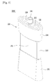
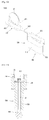
- Fig. 1 is a perspective view of the biomolecule extraction device according to an embodiment of the present invention.
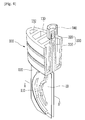
- Fig. 2 is an exploded perspective view of the biomolecule extraction device according to the embodiment of the present invention.
- Fig. 3 is a cut perspective view cutting the biomolecule extraction device according to the embodiment of the present invention in the major axis direction thereof.
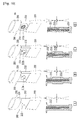
- Fig. 4 is a cut perspective view cutting the insertion part of the biomolecule extraction device according to the embodiment of the present invention in the minor axis direction.
- Fig. 5 is a cross sectional view illustrating the state of constant discharge of the biomass lysate after inserting the insertion part of the biomolecule extraction device according to the embodiment of the present invention into the body part.
- Fig. 6 is a cross sectional view of A-A' of Fig.
- Fig. 7 is a graph comparing the SA:V ratio of the biomolecule extraction device according to the embodiment of the present invention with the conventional methods.
- Fig. 8 is a graph comparing the extraction concentration of the biomolecule extraction device according to the embodiment of the present invention with the conventional methods.
- Fig. 9 is a diagram illustrating variables for designing an expanded discharge port for constant discharge after processing the sample.
- the biomolecule extraction device (1000) may largely comprise an insertion part (100) to which a sample containing collected biomass is fixed, a body part (200) which receives a lysis buffer inside and into which the insertion part (100) is inserted to extract biomolecule from the collected biomass, and at least one discharge part (300) provided at the insertion part (100) or the body part (200).
- the insertion part (100) may comprise at least one fixing part (110, 120) to which the sample is fixed.
- the fixing part (110, 120) may fix the sample by adhesive bonding or physical bonding, and the sample collecting biomass may be properly applied, for example, to a tape or membrane, etc. having an adhesive surface depending on the collection method.
- the fixing part (110, 120) fixes the sample by adhesive bonding
- a tape with an adhesive surface for example, a tape for obtaining samples (10) having an adhesive surface coated with an adhesive substance, etc.
- it may be configured to apply the adhesive substance to the fixing part (110, 120) and fix a non-adhesive sample.
- the fixing part (110, 120) fixes the sample by physical bonding, it can be fixed by insertion. This will be explained in another embodiment.
- a tape for obtaining samples (10) is used, and the insertion part (100) may comprise the fixing part (110, 120) adhered by having at least part of the tape for obtaining samples (10) in contact.
- the fixing part (110, 120) may comprise a first fixing part (110) formed on the inner side and a second fixing part (120) formed on the outer side of the first fixing part (100).
- the fixing part may comprise two of each of the first fixing part (110) and the second fixing part (120) on the same plane in a form extended perpendicularly downwards.
- the two tapes for obtaining samples (10) may be adhered to face each other with the first fixing part (110) and second fixing part (120) interposed.
- the tape for obtaining samples (10) may be in a disk form. In fact, it is possible to use products such as D-Squame disk manufactured by Cuderm of USA.
- One side of the tape for obtaining samples (10) can be an adhesive surface (12) and the other side can be a non-adhesive surface (14). If the adhesive surface (12) of the tape for obtaining samples (10) is attached to and then detached from the subject's skin, skin tissue comprising dead skin cells is collected by being attached to the adhesive surface (12), and protein can be extracted using this.
- the two tapes for obtaining samples (10) containing collected skin tissue as above may be attached and fixed so that the adhesive surfaces (12) face each other as separated at a certain interval with the first fixing part (110) and second fixing part (120) interposed.
- the tapes for obtaining samples (10) are attached to be separated at a certain interval with the first fixing part (110) and second fixing part (120) interposed, and this prevents the tapes for obtaining samples (10) from being adhered to each other.
- the two tapes for obtaining samples (10) are separated from each other as much as the thickness of the first fixing part (110) and second fixing part (120).
- a lysis buffer (20) fills in the space between the tapes for obtaining samples (10).
- the thickness of the fixing parts (110, 120) becomes a separation distance between the two tapes for obtaining samples (10) and also a parameter for determining the volume of the lysis buffer (20) to be introduced.
- the first fixing part (110) and the second fixing part (120) may have the same thickness or the first fixing part (110) positioned on the inner side may have a thickness thinner than that of the second fixing part (120).
- the first fixing part (110) may have a minimum thickness or even may be removed.
- the two tapes for obtaining samples (10) are spaced apart from each other by the thickness of the second fixing part (120) positioned on the other side.
- the part of the second fixing part (120) where the tape (10) is fixed has a size slightly greater than the outer circumference of the tape (10), and is engraved by the thickness of the tape, so that the insertion part (100) is not caught by protrusions of the tapes (10) or dead region is not generated when the insertion part (100) is inserted into the chamber (210) after the tapes (10) are fixed. Further, the first fixing part (110) positioned on the inner side prevents the tapes for obtaining samples (10) from being adhered to each other in their middle parts.
- the first fixing part (110) and the second fixing part (120) may be made into a linear bar shape having a predetermined thickness, but in the present embodiment, at least part of it is in a bent curved shape.
- a user can apply pressure without interference by the first fixing part (110) or the second fixing part (120) when applying pressure to a pressing part (212, see Fig. 10 ) to be explained below.
- the structures of bumps are added to the first fixing part (110) as necessary, which enable to minimize the contact surface of the tapes for obtaining samples (10) and maximize the surface area of the tapes for obtaining samples (10) exposed to the lysis buffer (20), and allow free movement of the lysis buffer (20).
- the body part (200) may comprise a chamber (210) which forms a predetermined space inside to receive the lysis buffer (20) and into which the tapes for obtaining samples (10) are inserted to be immerged in the lysis buffer (20).
- a base (220) is provided in the lower part of the chamber (210) to support and stand the chamber (210).
- the base (220) may be formed with the slope such that the cross sectional area increases downward in order for the body part (200) to stand stably.
- the thickness of the inside space of the chamber (210) is preferably configured such that each of non-contact surfaces (14) of the two tapes for obtaining samples (10) is adhered to the inner wall of the chamber (210) when the two tapes for obtaining samples (10) are inserted. Accordingly, most of all the lysis buffer (20) contained in the chamber (210) fill the space between the two tapes for obtaining samples (10).
- Such configuration is able to minimize dead space and to maximize the contact surface with the tapes for obtaining samples (10), which results in increasing the extraction concentration of biomolecule to a level which can be measured with a small amount of sample, even with applying a minimum amount of the lysis buffer (20).
- the biomolecule extraction device (1000) which makes the contact surface with the tapes for obtaining samples (10) relatively very large with respective to the volume of the lysis buffer (20), can dissolve cells only by being shaken once or twice and being left to stand.
- the insertion part (100) is inserted into and joined with the body part (200)
- strong fixing force can be maintained, and thus the lysis buffer (20) can fill the empty space between the tapes without additional compulsory external force or additional operation.
- the condition for contact can be effectively maintained. Thereby, the efficiency of extracting proteins can be rapidly increased.
- Fig. 7 compares the ratio (SA:V) of the surface area of the tapes for obtaining samples (10) in contact with the lysis buffer (20) to the buffer volume of the lysis buffer (20) contained in the chamber (210) of the biomolecule extraction device, Protein Extraction Device (PED, 1000) according to one embodiment of the present invention with the ratios according to conventional devices.
- SA:V ratio of the surface area of the tapes for obtaining samples (10) in contact with the lysis buffer (20) to the buffer volume of the lysis buffer (20) contained in the chamber (210) of the biomolecule extraction device, Protein Extraction Device (PED, 1000) according to one embodiment of the present invention with the ratios according to conventional devices.
- the SA:V ratios do not exceed 0.4.
- the cross-sectional area of the tapes (10) is 380 mm 2 and the amount of the lysis buffer (20) to be introduced is 200 L when using a product such as D-Squame disk manufactured by Cuderm Corporation, the calculated SA:V ratio is 1.9, which is over 0.4, but the SA:V ratio practically exceeds 1.4 in order to secure tolerance during the manufacture of injection molding of an extractor and spare space of a mold, etc.
- the SA:V ratio can be further increased by reducing a distance between the tapes for obtaining samples (10).
- a target discharge amount for one time is 35 ⁇ 40 ⁇ l and a substantial minimum gap that can be pressed when discharging is about 100 ⁇ m, while preventing the adhesion between the two tapes (10)
- the SA:V ratio can be raised up to about 9.15.
- the present invention makes the SA:V ratio relatively high and optimal, which enables to extract proteins with a minimum amount of samples and also raise the extract concentration.
- the concentration of the extracted total protein is around 40 ⁇ g/ml in both devices.
- the device according to the present invention it can be confirmed that it scored 63.4 ⁇ g/ml, which shows noticeably higher protein extraction efficiency.
- the entrance of the chamber (210) may be left open or comprise a shielding film (218).
- a user introduces the lysis buffer (20) into the chamber (210) before inserting the insertion part (100); in case the entrance comprises the shielding film (218), a predetermined amount of the lysis buffer (20) may be contained inside the chamber (210) in advance.
- the shielding film (218) consists of, for example, aluminum foil or vinyl film, etc., to seal the entrance of the chamber (210), and the user can insert the insertion part (100) after removing the shielding film (218), or push the insertion part (100) to penetrate the lysis buffer (218) so as to be inserted into the chamber (210).
- the position of the shielding film (218) is not fixed to the entrance of the chamber (21) but may be in the introduction part (230) as necessary.
- An introduction part (230) may be comprised on the upper part of the chamber (210).
- the introduction part (230) can be configured to extend upward from the entrance of the chamber (210) by a certain height.
- a sealing part (130) sealing the chamber (210) can be provided at one end of the insertion part (100), which is closely contacted to the inner wall of the introduction part (230) so as to correspond to the introduction part (230).
- the introduction part (230) is open upward, and when the tapes for obtaining samples (10) attached to the first fixing part (110) and the second fixing part (120) are inserted into the chamber (210), the sealing part (130) is fitted in the introduction part (230) to seal the chamber (210).
- the cross sections thereof may be shown in an oval shape. If the cross sections thereof are to be in a square shape, the adhesion force is not distributed evenly, and thus the sample may leak from the corners; and if the cross sections are made a circular shape, the adhesion force is distributed evenly, but they have a bulky volume.
- the present embodiment proposes a case where the cross sections of the introduction part (230) and sealing part (130) are in an oval shape.
- the sealing part (130) may comprise a plurality of reinforcing ribs (132) for reinforcing the strength thereof.
- the reinforcing ribs (132) boost the adhering force and fixing force of the sealing part (130) to the inner wall of the introduction part (230) while reinforcing the strength so that the sealing part (130) is not deformed when being joined with the body part (200).
- the biomolecule extraction device (1000) comprises at least one discharge part (300) equipped in the insertion part (100) or body part (200).
- the present embodiment describes an example where the discharge part (300) is provided to the insertion part.
- the discharge part (300) comprise a discharge flow path (310) which penetrates the sealing part (310) and allows the chamber (210) to communicate with the outside and discharge the sample, and an expanded discharge port (320) which is provided at the end of the discharge flow path (310) and has an inner diameter greater than the inner diameter of the discharge flow path (310) so as to constantly discharge the sample.
- the discharge flow path (310) communicates with the chamber (210) at one end and is connected to the expanded discharge port (320) at the other end, through which a sample having the protein extraction can be discharged.
- the discharge flow path (310) should be designed to have a minimum inner diameter before reaching the expended discharge port (320), in order to minimize the dead space and increase the total discharge amount.
- the discharge flow path (310) has a diameter of 850 ⁇ m, which is half of that of the expanded discharge port (320).
- the amount of the discharged sample can be adjusted to a constant amount by adjusting the size of the inner diameter of the expanded discharge port (320).
- the discharge amount can be calculated according to the following equation with referring to Fig. 9 .
- the discharge amount can be designed by means of the equilibrium state between the gravity force based on the weight of a single droplet of the extracted sample flowing out from the expanded discharge port (320) and the surface tension thereof trying to dangle at the discharge port.
- the discharge path (310) has an inner diameter of about 850 ⁇ m and the expanded discharge port (320) has an inner diameter of 1.7mm.
- the unit discharge amount of the sample is theoretically about 37.7 ⁇ l .
- the biomolecule extraction devices (1000) which is a simple device without a separate metering device, is capable of precisely discharging a constant amount of sample, and thus can produce a precise experimental result in a following operation performed after the sample is discharged into a test kit after extraction.
- a detachable sealing cap (140) may be additionally provided to the expanded discharge port (320), which prevents the sample from being randomly discharged and ensures the user's safety.
- a pressing part (212) which is formed on the outer wall of the chamber (210) such that external force can be applied when the user discharges the sample, and presses the sample, may be provided.
- a region corresponding to a hollow part the curved shape of the above-described first fixing part (110) forms in the outer wall of the chamber (210) forms a pressing part (212).
- the user applies pressure to the pressing part (212) to discharge the extracted sample, and when applying pressure, the inner walls of the chamber (210) are bent in a parabolic shape and thereby the extracted sample is squeezed out of the outlet.
- Fig. 10 illustrates perspective views and partial cross sectional views of modifications examples of the pressing part of the biomolecule extraction device according to the embodiment of the present invention, and diagrams illustrating deformation of the inner walls of the chamber when pressed.
- pressing parts (212a, 212b, 212c) modified in order to increase the recovery rate by applying uniform pressure are proposed.
- the pressing part (212a, 212b, 212c) may be made in an embossed form having a thickness greater than the surrounding outer wall.
- the pressing part (212a, 212b) may be configured to be made in a circular, embossed form as illustrated in Figs. 10(B) and 10(C) , or in a wheel shape as illustrated in Fig. 10(D) .
- a hollow is generated due to the failure to completely fill the structure of a mould with melted plastics when injection molding or the residual stress is focused when cooling after injection molding, which causes the structure's deformation or the ease generation of cracks.
- the pressing part in a wheel shape the problem occurred in the injection molding can be minimized.
- the sample can be discharged by applying pressure uniformly.
- biomolecule extraction devices may be configured to further comprise an engraved part (214) which is provided around the pressing part (212b, 212c) and has a thickness smaller than the surrounding outer wall.
- the engraved part (214) reduces the thickness around the pressing part (212), which enables the pressing part (212) to be easily bent.
- the inner wall of the chamber (210) to be pressurized is uniformly pressed from a parabolic shape in a linear manner, which can apply pressure uniformly, regardless of the shape of user's finger or the size of force to be applied, and thereby to increase the recovery rate of the sample.
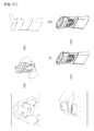
- Fig. 11 is a process diagram illustrating the process of extracting biomolecule (proteins) using the biomolecule extraction device according to an embodiment of the present invention.
- two tapes for obtaining samples (10) are attached to and then detached from the subject's skin to take the skin tissue. Then, the two tapes are adhered such that they are faced each other with the first fixing part (110) and the second fixing part (120) interposed.
- the lysis buffer (20) is introduced into the chamber (210) of the body part (200) and the insertion part (100) is inserted into the body part (200).
- the lysis buffer (20) is contained in the chamber (210) in advance and may be provided in a sealed state by the shielding film (218).
- the biomolecule extraction device (1000) is shaken once or twice with the tapes for obtaining samples (10) positioned inside the chamber (210) and is left to stand for 1 minute or several minutes as necessary.
- the cells are dissolved in the lysis buffer (20) and the proteins are extracted.
- the pressing part is pressed to discharge the sample having the extracted proteins into the inlet, and the test through antibody response can be proceeded.
- Fig. 12 is a perspective view of the biomolecule extraction device according to another embodiment of the present invention.
- Fig. 13 is a cross sectional view of the biomolecule extraction device according to another embodiment of the present invention.
- Fig. 14 is a plan view of the biomolecule extraction device according to another embodiment of the present invention.
- the biomolecule extraction device (2000) may also be made by comprising an insertion part (400), a body part (500) and a discharge part (600), briefly.
- the discharge part (600) may be equipped in the body part (500), not in the insertion part (400), unlike the previous embodiment.
- the insertion part (400) comprises a fixing part (410), and the tapes for obtaining samples (10) may be physically joined with the fixing part (410) by means of insertion or be adhered and fixed thereto by applying an adhesive.
- the present embodiment suggests a case where two tapes for obtaining samples (10) are fixed to the fixing part (410), but it is also possible to fix and use a single or three or more tapes for obtaining samples (10), as necessary.
- the insertion part (400) and the body part (500) may be connected to each other by a connection part(550).
- the body part (500) comprises an introduction part (530), and the insert part (400) may comprise a sealing part (430) to correspond to the introduction part.
- the body part (500) may comprise a chamber (510) which contains the lysis buffer, and the tapes for obtaining samples (10) which are fixed to the fixing part (410) can be inserted into the chamber (510) and the biomolecule can be extracted by the lysis buffer contained in the chamber (510) as the insertion part (400) is inserted into the body part (500).
- a pressing part (512) formed on the outer wall of the chamber (510) to discharge the extracted sample discharge through a discharge part (600).
- the biomolecule extraction device according to the embodiments of the present invention explained so far has the following effects.
- the biomolecule extraction device can perform the whole process of fixing a sample and injecting a buffer, assembling the insertion part and mixing, letting stand still and extraction, etc., within 5 minutes, which results in innovatively reducing the time to be taken, whereas most of the conventional protein or nucleic acid extraction methods required at least 20 to 30 minutes in total for mechanical or physical impact application, repetitive centrifugation, filtering and other process, etc., in order to break intercellular bonding or cell membrane.
- the biomolecule extraction device according to the present invention is performed in a non-impact and non-power manner, which needs neither broad experimental space nor a complicated system, ensures the user's safety, and is able to avoid harmful effect due to wastes because an extremely small amount of buffer is applied for a single use.
- the biomolecule extraction device can minimize the dead space, greatly increase the SA:V ratio, which allows the protein extraction without external force in a high concentration, and constantly discharge after extraction. Thus, a precise test with a test kit is possible.
- the biomolecule extraction device simplifies the protein extraction process in cells and can be independently used as one device without the need of additional devices, such as a centrifuge, a pipet, etc., and can be used without the user's skill. Thus, the user's convenience can be enhanced.
- the present invention was explained by referring to one example of the present invention (the example applied to the skin tissues), but a person skilled in the art can variously modify and change the present invention without deviating from the idea and scope of the present invention recited in the claims described below.
- the extraction device proposed in the present invention can be used for extracting from diverse biomass various biomolecules available for various analysis and diagnosis.
- the application scope includes biotechnology, molecular biology, medical science, pharmaceuticals, cosmetics, genetic engineering, diagnosis, health care, etc., but is not limited thereto.
- the modifications basically comprise the features of the claims of the present application, they all should be deemed to belong to the technical scope of the present invention.
Abstract
Description
- The present invention relates to a biomolecule extraction device and method thereof. More specifically, it relates to a biomolecule extraction device and method thereof that can enhance user's convenience by simplifying the process of extracting biomolecule such as protein or nucleic acid, etc., from biomass such as tissue and cell and saving time spent. As the ratio of the surface area of the sample to the amount of lysis buffer introduced is maximized, the concentration of biomolecule extraction is increased and the amount of buffer used is minimized. The present invention can also smoothly perform efficient testing without an extra device or equipment by allowing constant discharge of the extracted sample, and a method thereof.
- Cell lysis refers to a phenomenon where a cell membrane is ruptured and cell contents (cytoplasma) are exposed as a cell dissolves. Such cell lysis is a primary process for cell analysis and protein purification, which is widely used not only to extract/separate protein, but also to separate nucleic acid such as DNA (deoxyribonucleic acid) or RNA (ribonucleic acid) prior to an amplification process such as the PCR (polymerase chain reaction) used in molecular biology and molecular diagnostics, etc.
- Cell lysis methods for cell disruption largely include optical, acoustic, electrical and mechanical methods. Mostly, the methods are carried out in a form applying external force and stress in various mechanical and physical manner based on a lysis buffer.
- Optical cell lysis is a method destroying cells by irradiating laser micropulse on the target cell to form cavitation bubbles and destroying cells as the cavitation bubbles expand. Optical cell lysis has disadvantages that there is a possibility for the cell and protein to be degenerated due to the heat abruptly generated by applying a laser inside a specific cell or at a nearby location thereof, and that a separate device for generating lasers should be added.
- Acoustic cell lysis is a method destroying cells by introducing a cell solution or a suspension inside a chamber located in an ultrasonic water tank and applying ultrasonic waves. It is difficult to obtain consistent results from cell destruction using ultrasonic waves because it is difficult to form uniform energy distribution of ultrasound waves, it takes a lot of time for cell destruction, and the cell destruction using ultrasound waves may cause protein destruction or deformation due to the heat generated.
- Electrical cell lysis is a method destroying cells by applying an electric field to the cells to generate potential difference in cell membrane. It is similar in a way to other cell lysis methods such as the freezing-thawing method, heating method, osmotic pressure impact method, in terms of applying impact to cell walls. However, these methods have problems that protein in the cells may be damaged due to the thermal impact applied to the cells.
- Mechanical cell lysis uses presses, bead mills, etc. To be specific, presses perform cell disruption by filling an empty cylindrical body made of stainless steel often used in laboratory scale with cell paste, and extracting the cells to atmospheric pressure through a needle valve on the bottom of the cylinder under high pressure.
- High-speed bead mills comprise a grinding chamber filled with small glass or iron beads (20-50 units), and grind cells with high shearing force and impact force by rotating a circular disk or impeller attached to a driving shaft by a motor and stirring the beads.
- Such mechanical cell lysis has problems that it is difficult to apply the mechanical cell lysis to a small amount of samples, and expensive equipment, large space, multi-step process and long processing time are required.
- Meanwhile, a homogenizer performs cell lysis and disruption by having a user rotate a stick while filling an E-tube (Eppendorf-tube) or falcon tubes of various capacities, etc. with a lysis buffer. In this regard, there may be problems that in order to immerse a tape or disk for obtaining samples, a relatively large amount of lysis buffer is required and the sample may splash out or the buffer may overflow while rotating the stick.
- In addition, there are problems that in case of using the E-tube (Eppendorftube) or Petri dish itself, in order to apply the lysis buffer to a hydrophobic sample, a relatively large amount of buffer is required and additional work such as several times of pipetting, etc. using tools such as a pipette is required.
- Meanwhile, cell lysates according to cell lysis are widely used for special protein detection tests (western blotting) or immune precipitation, etc., and in case of extracting nucleic acid (DNA, RNA), they are applied to molecular diagnostics and gene analysis, etc. using PCR or sequencing. The above processes are performed by detecting the special protein itself or testing interaction between molecules.
- Here, for cell lysis, it is preferable to have a sufficient amount of biomolecule (protein or nucleic acid, etc.) product extracted from biomass, high purification concentration, and no loss or deformation of the extract. For doing so, an expensive protease inhibitor, etc. is used. Thus, since cell lysis of good quality for biomass sample should be performed fast and analyzed immediately, it would be necessary to simplify the process of extracting biomolecule and save cost and time spent therefor.
- However, as mentioned above, the conventional biomolecule extraction devices and methods thereof through cell lysis and disruption required an extra device or equipment such as a centrifugal separator and pipette, etc. while performing each steps. Plus, a complex process associated with the system had to be performed, thereby requiring a lot of space, cost and time.
- Also, in case of using a tape or disk for obtaining samples, there are problems that a lysis buffer where the sample can be immerged is required in order to maximize the contact surface of the sample and that due to the decrease in extraction concentration by applying a large amount of lysis buffer, a large amount of samples, i.e., biomass needs to be collected and additional work of chopping or dissociating the sample is required.
- This still leaves the problem of processing the residue which may contaminate the environment and affect human safety, after extracting biomolecule such as protein or nucleic acid from the sample.
- Thus, the necessity of a biomolecule extraction device has been raised where user's convenience can be enhanced by saving time and reducing space in need, resulted from simplifying the process of extracting biomolecule from biomass, and where consistent test results can be expected by minimizing the damage of the extracted biomolecule and extracting at a relatively high concentration while applying only a small amount of samples.
- Further, the biomolecule extraction device can not only increase the concentration of biomolecule extracted and reduce the amount of buffer used by minimizing dead space thereby maximizing the ratio of the surface area of the sample to the amount of lysis buffer introduced, but can also efficiently and smoothly perform testing by allowing constant discharge of the extracted sample.
- The examples of the present invention are intended to simplify the process of extracting biomolecule such as protein or nucleic acid, etc. from biomass such as tissue and cell and save time and space spent therefor to enhance user's convenience.
- Also, the examples of the present invention are intended not only to increase the concentration of biomolecule extracted and reduce the amount of buffer used by minimizing dead space thereby maximizing the ratio of the surface area of the sample to the amount of lysis buffer introduced.
- In addition, the examples of the present invention are intended to provide a biomolecule extraction device and method thereof that can be independently used without requiring an extra device or equipment to be applied, minimize damage of the extracted biomolecule, and expect consistent test results while applying only a small amount of samples.
- According to an aspect of one example in various applications of the present invention, a biomolecule extraction device may be provided, comprising an insertion part to which a sample containing collected biomass is fixed, a body part which receives a lysis buffer inside and into which the insertion part is inserted to extract biomolecule from the collected biomass, and at least one discharge part provided at the insertion part or the body part.
- The insertion part comprises at least one fixing part to which the sample is fixed.
- Also, the fixing part fixes the sample by adhesive bonding or physical bonding.
- Adhesive bonding of the fixing part is performed by using the adhesiveness present in the collected sample or applying an adhesive substance to the fixing part.
- Here, at least part of the fixing part is in a bent curved shape.
- Physical bonding of the fixing part fixes the sample by insertion bonding.
- At least part of the sample is fixed to the fixing part.
- The body part comprises a chamber having a predetermined space formed inside for receiving the lysis buffer and into which the insertion part is inserted and the lysis buffer is immersed.
- Here, the composition and component of the lysis buffer may vary depending on the type of the biomolecule to be extracted.
- The biomolecule extraction device according to the embodiments of the present invention further comprises a shielding film sealing the entrance of the chamber wherein the lysis buffer is received in the chamber in a sealed condition. In some cases, a lysis buffer of a certain amount required for a separate disposable container may be provided in a sealed condition.
- Meanwhile, the body part further comprises an introduction part guiding the insertion part to the chamber.
- Here, the insertion part comprises a sealing part formed in a form corresponding to the introduction part and having a close contact with the inner wall of the introduction part to seal the chamber.
- Also, the cross sections of the introduction part and the sealing part are formed in an oval or circular shape.
- Also, the sealing part comprises a reinforcing rib for reinforcing strength thereof.
- The discharge part comprises a discharge flow path and an expanded discharge port for constantly discharging the sample.
- The discharge flow path has an inner diameter smaller than the discharge port in order to minimize dead space.
- The biomolecule extraction device according to the embodiments of the present invention may further comprise a sealing cap detachably sealing the discharge part.
- The biomolecule extraction device according to the embodiments of the present invention may further comprise a pressing part being formed at the outer wall of the chamber and applying pressure allowing constant discharge of the sample.
- Here, the pressing part is formed in an embossed form having a thickness greater than that of the surrounding outer wall.
- Also, the biomolecule extraction device according to the embodiments of the present invention may further comprise an engraved part being formed around the pressing part and having a thickness smaller than the surrounding outer wall.
- Here, a ratio between the surface area of the sample in contact with the lysis buffer and the volume of the lysis buffer is from 0.4 to 9.15.
- According to another aspect of the present invention, the present invention may provide a method for extracting biomolecule, comprising fixing a sample containing collected biomass to an insertion part, inserting the insertion part into the body part receiving lysis buffer inside, and discharging biomolecule extracted from the biomass through a discharge part provided at any one of the insertion part or the body part.
- According to another aspect of the present invention, the extraction device comprises a chamber receiving a lysis buffer inside and an insertion part being inserted inside the chamber together with the two tapes for obtaining samples containing collected biomass which are adhered to the insertion part while being separated from each other and facing each other, wherein the non-adhesive surfaces of the two tapes for obtaining samples are respectively adhered to both inner walls of the chamber and the lysis buffer can fill in the space between the adhesive surfaces of the two tapes for obtaining samples.
- According to another aspect of the present invention, a tape for obtaining samples containing collected biomass is inserted in the lysis buffer received inside the chamber and the collected biomass is dissolved. A ratio between the surface area of the tape for obtaining sample in contact with the lysis buffer and the volume of the lysis buffer received inside the chamber may be from 0.4 to 9.15.
- The examples of the present invention are intended to simplify the process of extracting biomolecule such as protein or nucleic acid, etc. from biomass such as tissue and cell and save time and space spent therefor to enhance user's convenience.
- Also, the examples of the present invention are intended not only to increase the concentration of biomolecule extracted and reduce the amount of buffer used by minimizing dead space thereby maximizing the ratio of the surface area of the sample to the amount of lysis buffer introduced.
- In addition, the examples of the present invention are intended to provide a biomolecule extraction device and method thereof that can be independently used without requiring an extra device or equipment to be applied, minimize damage of the extracted biomolecule, and expect consistent test results while applying only a small amount of samples.
-
-
Fig. 1 is a perspective view of the biomolecule extraction device according to an embodiment of the present invention. -
Fig. 2 is an exploded perspective view of the biomolecule extraction device according to the embodiment of the present invention. -
Fig. 3 is a cut perspective view cutting the biomolecule extraction device according to the embodiment of the present invention in the major axis direction thereof. -
Fig. 4 is a cut perspective view cutting the insertion part of the biomolecule extraction device according to the embodiment of the present invention in the minor axis direction thereof. -
Fig. 5 is a cross sectional view illustrating the state of constant discharge of the biomass lysate after inserting the insertion part of the biomolecule extraction device according to the embodiment of the present invention into the body part. -
Fig. 6 is a cross sectional view of A-A' ofFig. 4 . -
Fig. 7 is a graph comparing the SA:V ratio of the biomolecule extraction device according to the embodiment of the present invention with the conventional methods. -
Fig. 8 is a graph comparing the extraction concentration of the biomolecule extraction device according to the embodiment of the present invention with the conventional methods. -
Fig. 9 is a diagram illustrating variables for designing an expanded discharge port for constant discharge after processing the sample. -
Fig. 10 illustrates perspective views and partial cross sectional views of modifications examples of the pressing part of the biomolecule extraction device according to the embodiment of the present invention, and diagrams illustrating deformation of the inner walls of the chamber when pressed. -
Fig. 11 is process diagram illustrating the process of extracting protein using the biomolecule extraction device suggested according to an embodiment of the present invention. -
Fig. 12 is a perspective view of the biomolecule extraction device according to another embodiment of the present invention. -
Fig. 13 is a cross sectional view of the biomolecule extraction device according to another embodiment of the present invention. -
Fig. 14 is a plan view of the biomolecule extraction device according to another embodiment of the present invention. - Hereinafter, with reference to the attached drawings, preferable embodiments of the present invention will be described in detail. However, the present invention is not limited to the embodiments described here, but may be realized in other forms. In fact, the embodiments introduced here are provided to complete the disclosure thoroughly and sufficiently deliver the idea of the present invention to a person having ordinary skill in the art. Throughout the specification, the same reference numerals refer to the same constitutional elements.
-
Fig. 1 is a perspective view of the biomolecule extraction device according to an embodiment of the present invention.Fig. 2 is an exploded perspective view of the biomolecule extraction device according to the embodiment of the present invention.Fig. 3 is a cut perspective view cutting the biomolecule extraction device according to the embodiment of the present invention in the major axis direction thereof.Fig. 4 is a cut perspective view cutting the insertion part of the biomolecule extraction device according to the embodiment of the present invention in the minor axis direction.Fig. 5 is a cross sectional view illustrating the state of constant discharge of the biomass lysate after inserting the insertion part of the biomolecule extraction device according to the embodiment of the present invention into the body part.Fig. 6 is a cross sectional view of A-A' ofFig. 4 .Fig. 7 is a graph comparing the SA:V ratio of the biomolecule extraction device according to the embodiment of the present invention with the conventional methods.Fig. 8 is a graph comparing the extraction concentration of the biomolecule extraction device according to the embodiment of the present invention with the conventional methods.Fig. 9 is a diagram illustrating variables for designing an expanded discharge port for constant discharge after processing the sample. - Referring to
Figs. 1-9 , the biomolecule extraction device (1000) according to an embodiment of the present invention may largely comprise an insertion part (100) to which a sample containing collected biomass is fixed, a body part (200) which receives a lysis buffer inside and into which the insertion part (100) is inserted to extract biomolecule from the collected biomass, and at least one discharge part (300) provided at the insertion part (100) or the body part (200). - The insertion part (100) may comprise at least one fixing part (110, 120) to which the sample is fixed. The fixing part (110, 120) may fix the sample by adhesive bonding or physical bonding, and the sample collecting biomass may be properly applied, for example, to a tape or membrane, etc. having an adhesive surface depending on the collection method.
- In case the fixing part (110, 120) fixes the sample by adhesive bonding, a tape with an adhesive surface, for example, a tape for obtaining samples (10) having an adhesive surface coated with an adhesive substance, etc., is used, and bonded to the fixing part using the adhesiveness left on the tape after collecting sample. Alternatively, it may be configured to apply the adhesive substance to the fixing part (110, 120) and fix a non-adhesive sample.
- In case the fixing part (110, 120) fixes the sample by physical bonding, it can be fixed by insertion. This will be explained in another embodiment.
- In the present embodiment, a tape for obtaining samples (10) is used, and the insertion part (100) may comprise the fixing part (110, 120) adhered by having at least part of the tape for obtaining samples (10) in contact.
- Here, the fixing part (110, 120) may comprise a first fixing part (110) formed on the inner side and a second fixing part (120) formed on the outer side of the first fixing part (100). The fixing part may comprise two of each of the first fixing part (110) and the second fixing part (120) on the same plane in a form extended perpendicularly downwards.
- Also, the two tapes for obtaining samples (10) may be adhered to face each other with the first fixing part (110) and second fixing part (120) interposed. The tape for obtaining samples (10) may be in a disk form. In fact, it is possible to use products such as D-Squame disk manufactured by Cuderm of USA.
- One side of the tape for obtaining samples (10) can be an adhesive surface (12) and the other side can be a non-adhesive surface (14). If the adhesive surface (12) of the tape for obtaining samples (10) is attached to and then detached from the subject's skin, skin tissue comprising dead skin cells is collected by being attached to the adhesive surface (12), and protein can be extracted using this.
- The two tapes for obtaining samples (10) containing collected skin tissue as above may be attached and fixed so that the adhesive surfaces (12) face each other as separated at a certain interval with the first fixing part (110) and second fixing part (120) interposed. Here, since the tapes for obtaining samples (10) are attached to be separated at a certain interval with the first fixing part (110) and second fixing part (120) interposed, and this prevents the tapes for obtaining samples (10) from being adhered to each other.
- The two tapes for obtaining samples (10) are separated from each other as much as the thickness of the first fixing part (110) and second fixing part (120). When the insertion part (10) is inserted into the body part (200), a lysis buffer (20) fills in the space between the tapes for obtaining samples (10).
- Thus, the thickness of the fixing parts (110, 120) becomes a separation distance between the two tapes for obtaining samples (10) and also a parameter for determining the volume of the lysis buffer (20) to be introduced.
- Here, the first fixing part (110) and the second fixing part (120) may have the same thickness or the first fixing part (110) positioned on the inner side may have a thickness thinner than that of the second fixing part (120). In case a distance spaced enough not to be adhered to each other due to the rigidity of the tapes (10) is maintained, the first fixing part (110) may have a minimum thickness or even may be removed. In this case, the two tapes for obtaining samples (10) are spaced apart from each other by the thickness of the second fixing part (120) positioned on the other side. The part of the second fixing part (120) where the tape (10) is fixed has a size slightly greater than the outer circumference of the tape (10), and is engraved by the thickness of the tape, so that the insertion part (100) is not caught by protrusions of the tapes (10) or dead region is not generated when the insertion part (100) is inserted into the chamber (210) after the tapes (10) are fixed. Further, the first fixing part (110) positioned on the inner side prevents the tapes for obtaining samples (10) from being adhered to each other in their middle parts.
- The first fixing part (110) and the second fixing part (120) may be made into a linear bar shape having a predetermined thickness, but in the present embodiment, at least part of it is in a bent curved shape. By configuring part of the first fixing part (110) and the second fixing part (120) to be in a curved shape, a user can apply pressure without interference by the first fixing part (110) or the second fixing part (120) when applying pressure to a pressing part (212, see
Fig. 10 ) to be explained below. The structures of bumps are added to the first fixing part (110) as necessary, which enable to minimize the contact surface of the tapes for obtaining samples (10) and maximize the surface area of the tapes for obtaining samples (10) exposed to the lysis buffer (20), and allow free movement of the lysis buffer (20). - The body part (200) may comprise a chamber (210) which forms a predetermined space inside to receive the lysis buffer (20) and into which the tapes for obtaining samples (10) are inserted to be immerged in the lysis buffer (20).
- A base (220) is provided in the lower part of the chamber (210) to support and stand the chamber (210). The base (220) may be formed with the slope such that the cross sectional area increases downward in order for the body part (200) to stand stably.
- The thickness of the inside space of the chamber (210) is preferably configured such that each of non-contact surfaces (14) of the two tapes for obtaining samples (10) is adhered to the inner wall of the chamber (210) when the two tapes for obtaining samples (10) are inserted. Accordingly, most of all the lysis buffer (20) contained in the chamber (210) fill the space between the two tapes for obtaining samples (10).
- Such configuration is able to minimize dead space and to maximize the contact surface with the tapes for obtaining samples (10), which results in increasing the extraction concentration of biomolecule to a level which can be measured with a small amount of sample, even with applying a minimum amount of the lysis buffer (20).
- In particular, conventionally, since skin tissue samples adhered to the tapes for obtaining samples (10) are hydrophobic and thus the lysis buffer (20) did not spontaneously spread out, external force should be compulsorily applied or additional operation should be performed by a device. Also, in order to avoid a problem that the tapes (10) rise up when immerged, external force should be consistently applied to the tapes (10).
- Also, as explained above, the biomolecule extraction device (1000) according to one embodiment of the present invention, which makes the contact surface with the tapes for obtaining samples (10) relatively very large with respective to the volume of the lysis buffer (20), can dissolve cells only by being shaken once or twice and being left to stand. When the insertion part (100) is inserted into and joined with the body part (200), strong fixing force can be maintained, and thus the lysis buffer (20) can fill the empty space between the tapes without additional compulsory external force or additional operation. The condition for contact can be effectively maintained. Thereby, the efficiency of extracting proteins can be rapidly increased.
- These matters can be confirmed from the graphs of
Figs. 7 and 8. Fig. 7 compares the ratio (SA:V) of the surface area of the tapes for obtaining samples (10) in contact with the lysis buffer (20) to the buffer volume of the lysis buffer (20) contained in the chamber (210) of the biomolecule extraction device, Protein Extraction Device (PED, 1000) according to one embodiment of the present invention with the ratios according to conventional devices. - In the cases of applying conventional Petri dish and Eppendorf tube, the SA:V ratios do not exceed 0.4. By comparison, in the case of applying the device of the present invention, since the cross-sectional area of the tapes (10) is 380 mm2 and the amount of the lysis buffer (20) to be introduced is 200 L when using a product such as D-Squame disk manufactured by Cuderm Corporation, the calculated SA:V ratio is 1.9, which is over 0.4, but the SA:V ratio practically exceeds 1.4 in order to secure tolerance during the manufacture of injection molding of an extractor and spare space of a mold, etc.
- In theory, the SA:V ratio can be further increased by reducing a distance between the tapes for obtaining samples (10). However, considering that a target discharge amount for one time is 35~40µℓ and a substantial minimum gap that can be pressed when discharging is about 100µm, while preventing the adhesion between the two tapes (10), the SA:V ratio can be raised up to about 9.15.
- As such, the present invention makes the SA:V ratio relatively high and optimal, which enables to extract proteins with a minimum amount of samples and also raise the extract concentration.
- Indeed, as can be confirmed from the graph of
Fig. 8 , in the case of introducing the lysis buffer in the same amount (250µℓ/disk) into the conventional Petri dish and Eppendorf tube, the concentration of the extracted total protein is around 40µg/ml in both devices. However, in the case of the device according to the present invention, it can be confirmed that it scored 63.4µg/ml, which shows noticeably higher protein extraction efficiency. - Meanwhile, the entrance of the chamber (210) may be left open or comprise a shielding film (218). In case the entrance is left open, a user introduces the lysis buffer (20) into the chamber (210) before inserting the insertion part (100); in case the entrance comprises the shielding film (218), a predetermined amount of the lysis buffer (20) may be contained inside the chamber (210) in advance.
- The shielding film (218) consists of, for example, aluminum foil or vinyl film, etc., to seal the entrance of the chamber (210), and the user can insert the insertion part (100) after removing the shielding film (218), or push the insertion part (100) to penetrate the lysis buffer (218) so as to be inserted into the chamber (210). The position of the shielding film (218) is not fixed to the entrance of the chamber (21) but may be in the introduction part (230) as necessary.
- An introduction part (230) may be comprised on the upper part of the chamber (210). The introduction part (230) can be configured to extend upward from the entrance of the chamber (210) by a certain height. Further, a sealing part (130) sealing the chamber (210) can be provided at one end of the insertion part (100), which is closely contacted to the inner wall of the introduction part (230) so as to correspond to the introduction part (230).
- That is, the introduction part (230) is open upward, and when the tapes for obtaining samples (10) attached to the first fixing part (110) and the second fixing part (120) are inserted into the chamber (210), the sealing part (130) is fitted in the introduction part (230) to seal the chamber (210).
- Further, if the introduction part (230) and the sealing part (130) are cut horizontally, the cross sections thereof may be shown in an oval shape. If the cross sections thereof are to be in a square shape, the adhesion force is not distributed evenly, and thus the sample may leak from the corners; and if the cross sections are made a circular shape, the adhesion force is distributed evenly, but they have a bulky volume. Thus, the present embodiment proposes a case where the cross sections of the introduction part (230) and sealing part (130) are in an oval shape. Here, the sealing part (130) may comprise a plurality of reinforcing ribs (132) for reinforcing the strength thereof. The reinforcing ribs (132) boost the adhering force and fixing force of the sealing part (130) to the inner wall of the introduction part (230) while reinforcing the strength so that the sealing part (130) is not deformed when being joined with the body part (200).
- Meanwhile, the biomolecule extraction device (1000) according to one embodiment of the present invention comprises at least one discharge part (300) equipped in the insertion part (100) or body part (200). The present embodiment describes an example where the discharge part (300) is provided to the insertion part.
- Here, the discharge part (300) comprise a discharge flow path (310) which penetrates the sealing part (310) and allows the chamber (210) to communicate with the outside and discharge the sample, and an expanded discharge port (320) which is provided at the end of the discharge flow path (310) and has an inner diameter greater than the inner diameter of the discharge flow path (310) so as to constantly discharge the sample.
- The discharge flow path (310) communicates with the chamber (210) at one end and is connected to the expanded discharge port (320) at the other end, through which a sample having the protein extraction can be discharged. The discharge flow path (310) should be designed to have a minimum inner diameter before reaching the expended discharge port (320), in order to minimize the dead space and increase the total discharge amount. In the present embodiment, the discharge flow path (310) has a diameter of 850 µm, which is half of that of the expanded discharge port (320).
- The amount of the discharged sample can be adjusted to a constant amount by adjusting the size of the inner diameter of the expanded discharge port (320). The discharge amount can be calculated according to the following equation with referring to
Fig. 9 . To be specific, the discharge amount can be designed by means of the equilibrium state between the gravity force based on the weight of a single droplet of the extracted sample flowing out from the expanded discharge port (320) and the surface tension thereof trying to dangle at the discharge port. -


W : weight of droplet, r : radius of outlet, γ : surface tension - In the present embodiment, the discharge path (310) has an inner diameter of about 850µm and the expanded discharge port (320) has an inner diameter of 1.7mm. When the inner diameter of the expanded discharge port (320) is designed to be 1.7mm, the unit discharge amount of the sample is theoretically about 37.7µℓ.
- After producing actual products, 10 biomolecule extraction devices (10) were measured and tested twice under each condition by applying deionized water and the lysis buffer (20). As a result, the actual unit discharge amount was measured as 35.5±2µℓ, as shown in the following Table 1, and thus it can be confirmed that the sample is substantially constantly discharged through the biomolecule extraction devices(1000) according to the present invention.
[Table 1] Dev No. D.I. water(µℓ) Lysis Buffer(µℓ) 1st droplet 2nd droplet 1st droplet 2nd droplet 1 33 36 40 33 2 33 36 35 35 3 34 37 48 36 4 33 33 35 36 5 32 30 33 34 6 35 35 35 36 7 36 35 35 36 8 37 38 37 35 9 30 34 35 34 10 30 34 35 37 Average 33.3 34.8 35.8 35.2 SD 2.3 2.3 2.0 1.2 %CV 6.94 6.47 5.56 3.49 - As such, the biomolecule extraction devices (1000) according to one embodiment of the present invention, which is a simple device without a separate metering device, is capable of precisely discharging a constant amount of sample, and thus can produce a precise experimental result in a following operation performed after the sample is discharged into a test kit after extraction.
- A detachable sealing cap (140) may be additionally provided to the expanded discharge port (320), which prevents the sample from being randomly discharged and ensures the user's safety.
- Meanwhile, a pressing part (212), which is formed on the outer wall of the chamber (210) such that external force can be applied when the user discharges the sample, and presses the sample, may be provided. Basically, a region corresponding to a hollow part the curved shape of the above-described first fixing part (110) forms in the outer wall of the chamber (210) forms a pressing part (212).
- Specifically, the user applies pressure to the pressing part (212) to discharge the extracted sample, and when applying pressure, the inner walls of the chamber (210) are bent in a parabolic shape and thereby the extracted sample is squeezed out of the outlet.
-
Fig. 10 illustrates perspective views and partial cross sectional views of modifications examples of the pressing part of the biomolecule extraction device according to the embodiment of the present invention, and diagrams illustrating deformation of the inner walls of the chamber when pressed. - As shown in
Fig. 10 , pressing parts (212a, 212b, 212c) modified in order to increase the recovery rate by applying uniform pressure are proposed. - First, in the present embodiment, the pressing part (212a, 212b, 212c) may be made in an embossed form having a thickness greater than the surrounding outer wall. The pressing part (212a, 212b) may be configured to be made in a circular, embossed form as illustrated in
Figs. 10(B) and 10(C) , or in a wheel shape as illustrated inFig. 10(D) . In the case of a structure having a thickness or height of 2 mm or more, a hollow is generated due to the failure to completely fill the structure of a mould with melted plastics when injection molding or the residual stress is focused when cooling after injection molding, which causes the structure's deformation or the ease generation of cracks. In the case of the pressing part in a wheel shape, the problem occurred in the injection molding can be minimized. By means of the thus-configured pressing part (212a, 212b, 212c), the sample can be discharged by applying pressure uniformly. - Further, the biomolecule extraction devices according to the embodiments of the present invention may be configured to further comprise an engraved part (214) which is provided around the pressing part (212b, 212c) and has a thickness smaller than the surrounding outer wall. The engraved part (214) reduces the thickness around the pressing part (212), which enables the pressing part (212) to be easily bent.
- According to the above-explained modifications, the inner wall of the chamber (210) to be pressurized is uniformly pressed from a parabolic shape in a linear manner, which can apply pressure uniformly, regardless of the shape of user's finger or the size of force to be applied, and thereby to increase the recovery rate of the sample.
-
Fig. 11 is a process diagram illustrating the process of extracting biomolecule (proteins) using the biomolecule extraction device according to an embodiment of the present invention. - Hereinafter, we will explain a method for extracting biomolecule (proteins) by means of the biomolecule extraction device (1000) according to one embodiment of the present invention, with reference to
Figs. 1 to 11 . - Then, the lysis buffer (20) is introduced into the chamber (210) of the body part (200) and the insertion part (100) is inserted into the body part (200). Here, the lysis buffer (20) is contained in the chamber (210) in advance and may be provided in a sealed state by the shielding film (218).
- Thereafter, the biomolecule extraction device (1000) is shaken once or twice with the tapes for obtaining samples (10) positioned inside the chamber (210) and is left to stand for 1 minute or several minutes as necessary. In this process, the cells are dissolved in the lysis buffer (20) and the proteins are extracted.
- Then, after removing the sealing cap (140), the pressing part is pressed to discharge the sample having the extracted proteins into the inlet, and the test through antibody response can be proceeded.
-
Fig. 12 is a perspective view of the biomolecule extraction device according to another embodiment of the present invention.Fig. 13 is a cross sectional view of the biomolecule extraction device according to another embodiment of the present invention.Fig. 14 is a plan view of the biomolecule extraction device according to another embodiment of the present invention. - With reference to
Figs. 12 to 14 , the biomolecule extraction device (2000) according to another embodiment of the present invention may also be made by comprising an insertion part (400), a body part (500) and a discharge part (600), briefly. - Here, the discharge part (600) may be equipped in the body part (500), not in the insertion part (400), unlike the previous embodiment. The insertion part (400) comprises a fixing part (410), and the tapes for obtaining samples (10) may be physically joined with the fixing part (410) by means of insertion or be adhered and fixed thereto by applying an adhesive.
- The present embodiment suggests a case where two tapes for obtaining samples (10) are fixed to the fixing part (410), but it is also possible to fix and use a single or three or more tapes for obtaining samples (10), as necessary.
- The insertion part (400) and the body part (500) may be connected to each other by a connection part(550). The body part (500) comprises an introduction part (530), and the insert part (400) may comprise a sealing part (430) to correspond to the introduction part.
- Meanwhile, the body part (500) may comprise a chamber (510) which contains the lysis buffer, and the tapes for obtaining samples (10) which are fixed to the fixing part (410) can be inserted into the chamber (510) and the biomolecule can be extracted by the lysis buffer contained in the chamber (510) as the insertion part (400) is inserted into the body part (500).
- Once the biomolecule extraction is completed, the user presses a pressing part (512) formed on the outer wall of the chamber (510) to discharge the extracted sample discharge through a discharge part (600). Here, various modifications explained in the previous embodiment can be equally applied to the pressing part (512).
- The biomolecule extraction device according to the embodiments of the present invention explained so far has the following effects.
- First, the biomolecule extraction device according to the present invention can perform the whole process of fixing a sample and injecting a buffer, assembling the insertion part and mixing, letting stand still and extraction, etc., within 5 minutes, which results in innovatively reducing the time to be taken, whereas most of the conventional protein or nucleic acid extraction methods required at least 20 to 30 minutes in total for mechanical or physical impact application, repetitive centrifugation, filtering and other process, etc., in order to break intercellular bonding or cell membrane.
- Second, the biomolecule extraction device according to the present invention is performed in a non-impact and non-power manner, which needs neither broad experimental space nor a complicated system, ensures the user's safety, and is able to avoid harmful effect due to wastes because an extremely small amount of buffer is applied for a single use.
- Third, the biomolecule extraction device according to the present invention can minimize the dead space, greatly increase the SA:V ratio, which allows the protein extraction without external force in a high concentration, and constantly discharge after extraction. Thus, a precise test with a test kit is possible.
- Fourth, the biomolecule extraction device according to the present invention simplifies the protein extraction process in cells and can be independently used as one device without the need of additional devices, such as a centrifuge, a pipet, etc., and can be used without the user's skill. Thus, the user's convenience can be enhanced.
- In the above, the present invention was explained by referring to one example of the present invention (the example applied to the skin tissues), but a person skilled in the art can variously modify and change the present invention without deviating from the idea and scope of the present invention recited in the claims described below. The extraction device proposed in the present invention can be used for extracting from diverse biomass various biomolecules available for various analysis and diagnosis. The application scope includes biotechnology, molecular biology, medical science, pharmaceuticals, cosmetics, genetic engineering, diagnosis, health care, etc., but is not limited thereto. Thus, if the modifications basically comprise the features of the claims of the present application, they all should be deemed to belong to the technical scope of the present invention.
Claims (23)
- A biomolecule extraction device, comprising:an insertion part to which a sample containing collected biomass is fixed;a body part which receives a lysis buffer inside and into which the insertion part is inserted to extract biomolecule from the collected biomass; andat least one discharge part provided at the insertion part or the body part.
- The biomolecule extraction device according to claim 1,
characterized in that the insertion part comprises at least one fixing part to which the sample is fixed. - The biomolecule extraction device according to claim 2,
characterized in that the fixing part fixes the sample by adhesive bonding or physical bonding. - The biomolecule extraction device according to claim 3,
characterized in that the adhesive bonding of the fixing part is performed by using the adhesiveness present in the collected sample or applying an adhesive substance to the fixing part. - The biomolecule extraction device according to claim 3,
characterized in that at least part of the fixing part is in a bent curved shape. - The biomolecule extraction device according to claim 3,
characterized in that physical bonding of the fixing part fixes the sample by insertion bonding. - The biomolecule extraction device according to claim 2,
characterized in that at least part of the sample is fixed to the fixing part. - The biomolecule extraction device according to claim 1,
characterized in that the body part comprises a chamber having a predetermined space formed inside for receiving the lysis buffer and into which the insertion part is inserted and the lysis buffer is immersed. - The biomolecule extraction device according to claim 8,
further comprising a shielding film sealing the entrance of the chamber, characterized in that the lysis buffer is received in the chamber in a sealed condition. - The biomolecule extraction device according to claim 8,
characterized in that the body part further comprises an introduction part guiding the insertion part to the chamber. - The biomolecule extraction device according to claim 8,
characterized in that the insertion part comprises a sealing part formed in a form corresponding to the introduction part and having a close contact with the inner wall of the introduction part to seal the chamber. - The biomolecule extraction device according to claim 11,
characterized in that the cross sections of the introduction part and the sealing part are formed in an oval or circular shape. - The biomolecule extraction device according to claim 11,
characterized in that the sealing part comprises a reinforcing rib for reinforcing strength thereof. - The biomolecule extraction device according to claim 1,
characterized in that the discharge part comprises a discharge flow path and an expanded discharge port for constantly discharging the sample. - The biomolecule extraction device according to claim 14,
characterized in that the discharge flow path has an inner diameter smaller than the discharge port in order to minimize dead space. - The biomolecule extraction device according to claim 14,
further comprising a sealing cap detachably sealing the discharge part. - The biomolecule extraction device according to claim 8,
further comprising a pressing part being formed at the outer wall of the chamber and applying pressure allowing constant discharge of the sample. - The biomolecule extraction device according to claim 17,
characterized in that the pressing part is formed in an embossed form having a thickness greater than that of the surrounding outer wall. - The biomolecule extraction device according to claim 17,
further comprising an engraved part being formed around the pressing part and having a thickness smaller than the surrounding outer wall. - The biomolecule extraction device according to claim 1,
characterized in that a ratio between the surface area of the sample in contact with the lysis buffer and the volume of the lysis buffer is from 0.4 to 9.15. - A method for extracting biomolecule, comprising:fixing a sample containing collected biomass to an insertion part;inserting the insertion part into the body part receiving lysis buffer inside; anddischarging biomolecule extracted from the biomass through a discharge part provided at any one of the insertion part or the body part.
- The method according to claim 21,
characterized in that the sample is fixed to the insertion part by adhesive bonding or physical bonding. - The method according to claim 21,
characterized in that the sample has a ratio between the surface area of the sample in contact with the lysis buffer and the volume of the lysis buffer is from 0.4 to 9.15.
Applications Claiming Priority (2)
| Application Number | Priority Date | Filing Date | Title |
|---|---|---|---|
| KR1020130084110A KR101507234B1 (en) | 2013-07-17 | 2013-07-17 | biomolecule extraction device and method thereof |
| PCT/KR2014/006515 WO2015009085A1 (en) | 2013-07-17 | 2014-07-17 | Biomolecule extraction device and biomolecule extraction method |
Publications (4)
| Publication Number | Publication Date |
|---|---|
| EP3023486A1 true EP3023486A1 (en) | 2016-05-25 |
| EP3023486A4 EP3023486A4 (en) | 2017-03-29 |
| EP3023486B1 EP3023486B1 (en) | 2019-03-13 |
| EP3023486B8 EP3023486B8 (en) | 2019-07-17 |
Family
ID=52346458
Family Applications (1)
| Application Number | Title | Priority Date | Filing Date |
|---|---|---|---|
| EP14826368.4A Active EP3023486B8 (en) | 2013-07-17 | 2014-07-17 | Biomolecule extraction device and biomolecule extraction method |
Country Status (12)
| Country | Link |
|---|---|
| US (1) | US10520404B2 (en) |
| EP (1) | EP3023486B8 (en) |
| JP (1) | JP6525283B2 (en) |
| KR (1) | KR101507234B1 (en) |
| CN (1) | CN105829520B (en) |
| AU (1) | AU2014290933B2 (en) |
| CA (1) | CA2917132C (en) |
| ES (1) | ES2729620T3 (en) |
| RU (1) | RU2664477C2 (en) |
| SG (1) | SG11201600226RA (en) |
| WO (1) | WO2015009085A1 (en) |
| ZA (1) | ZA201600363B (en) |
Families Citing this family (6)
| Publication number | Priority date | Publication date | Assignee | Title |
|---|---|---|---|---|
| KR101865300B1 (en) * | 2016-05-27 | 2018-06-07 | 주식회사 하이딥 | Method for controlling behavior of character in touch input device |
| FR3060755A1 (en) | 2016-12-16 | 2018-06-22 | L'oreal | DIAGNOSTIC METHOD FOR A SKIN WITH DROUGHT SIGNS |
| FR3061305B1 (en) | 2016-12-23 | 2021-02-12 | Oreal | METHOD OF DIAGNOSING THE AESTHETIC QUALITIES OF THE SKIN |
| FR3070494B1 (en) | 2017-08-23 | 2022-07-01 | Oreal | DIAGNOSTIC METHOD FOR SKIN SHOWING SIGNS OF AGING |
| CN110885356A (en) * | 2019-12-19 | 2020-03-17 | 吉林工程技术师范学院 | Soybean draws electromagnetic cracking device for polypeptide |
| WO2022113112A1 (en) * | 2020-11-27 | 2022-06-02 | Reliance Industries Limited | Device for rna extraction for sars-cov-2 detection |
Citations (7)
| Publication number | Priority date | Publication date | Assignee | Title |
|---|---|---|---|---|
| WO2000012675A1 (en) * | 1998-08-27 | 2000-03-09 | Xtrana Inc. | Self-contained device integrating nucleic acid extraction, amplification and detection |
| US20020012982A1 (en) * | 2000-07-13 | 2002-01-31 | Invitrogen Corporation | Methods and compositions for rapid protein and peptide extraction and isolation using a lysis matrix |
| EP1574564A1 (en) * | 2002-12-17 | 2005-09-14 | ARKRAY, Inc. | Microorganism or cell collecting method, and microorganism or cell collecting implement used for the method |
| WO2009073152A1 (en) * | 2007-11-28 | 2009-06-11 | Smart Tube, Inc. | Devices, systems and methods for the collection, stimulation, stabilization, and analysis of a biological sample |
| US20090258382A1 (en) * | 2007-12-15 | 2009-10-15 | Schultz Gregory S | Novel devices for the detection of the presence and/or activity of proteases in biological samples |
| CN201459139U (en) * | 2009-07-03 | 2010-05-12 | 公安部物证鉴定中心 | Extraction device of fallen cells |
| US20110300609A1 (en) * | 2008-06-27 | 2011-12-08 | Postech Academy-Industry Foundation | Nucleic acid extraction apparatus |
Family Cites Families (15)
| Publication number | Priority date | Publication date | Assignee | Title |
|---|---|---|---|---|
| JP3490560B2 (en) * | 1995-11-16 | 2004-01-26 | 日東電工株式会社 | Method for detecting human hemoglobin in feces |
| JP4357159B2 (en) * | 2002-07-22 | 2009-11-04 | ニプロ株式会社 | Chemical container |
| WO2006012884A1 (en) * | 2004-07-30 | 2006-02-09 | Adexter Technology Limited | Device and method for isolating cells, bioparticles and/or molecules from liquids designed to be used for the treatment of human diseases |
| DE102005054924B4 (en) * | 2005-11-17 | 2012-06-14 | Siemens Ag | Apparatus and method for extracting a swab sample |
| DK1956969T3 (en) * | 2005-12-09 | 2012-01-30 | Dna Genotek Inc | Container system for releasable storage of fabric |
| WO2009012808A1 (en) * | 2007-07-23 | 2009-01-29 | Tecan Trading Ag | Collection/extraction container for biological material in forensic samples |
| KR100901485B1 (en) * | 2007-08-27 | 2009-06-08 | 연세대학교 산학협력단 | Apparatus for extracting dna from livestock and extracting method using thereof |
| JP2009150830A (en) * | 2007-12-21 | 2009-07-09 | Olympus Corp | Sample collection member, sample taking-out member, and sample collection kit equipped therewith |
| EP2333511A1 (en) * | 2008-08-29 | 2011-06-15 | Olympus Corporation | Specimen container |
| KR101030848B1 (en) * | 2008-11-07 | 2011-04-22 | 연세대학교 산학협력단 | Portable Aparatus and method for Real-Time DNA Extraction from Animal Tissue |
| EP2394152B1 (en) * | 2009-02-03 | 2019-05-01 | ANDE Corporation | Nucleic acid purification |
| JP2010271259A (en) * | 2009-05-25 | 2010-12-02 | Sysmex Corp | Method, device, cartridge and kit for analyzing biological component |
| KR101049201B1 (en) * | 2009-10-29 | 2011-07-14 | 토자이홀딩스 주식회사 | Biodevices for the Extraction of Hematopoietic Stem Cells and Mesenchymal Stem Cells in Peripheral Blood |
| CA2789447A1 (en) | 2010-02-12 | 2011-08-18 | Northwestern University | Assay card for sample acquisition, treatment and reaction |
| FR2959775B1 (en) | 2010-05-07 | 2012-05-25 | Peugeot Citroen Automobiles Sa | METHOD FOR ESTIMATING FRESH AIR QUANTITY, RECORDING MEDIUM AND ESTIMATOR FOR THIS METHOD, VEHICLE EQUIPPED WITH SAID ESTIMATOR |
-
2013
- 2013-07-17 KR KR1020130084110A patent/KR101507234B1/en active IP Right Grant
-
2014
- 2014-07-17 EP EP14826368.4A patent/EP3023486B8/en active Active
- 2014-07-17 CA CA2917132A patent/CA2917132C/en active Active
- 2014-07-17 ES ES14826368T patent/ES2729620T3/en active Active
- 2014-07-17 WO PCT/KR2014/006515 patent/WO2015009085A1/en active Application Filing
- 2014-07-17 AU AU2014290933A patent/AU2014290933B2/en active Active
- 2014-07-17 JP JP2016527936A patent/JP6525283B2/en active Active
- 2014-07-17 CN CN201480040355.1A patent/CN105829520B/en active Active
- 2014-07-17 RU RU2016103926A patent/RU2664477C2/en active
- 2014-07-17 SG SG11201600226RA patent/SG11201600226RA/en unknown
- 2014-07-17 US US14/905,268 patent/US10520404B2/en active Active
-
2016
- 2016-01-15 ZA ZA2016/00363A patent/ZA201600363B/en unknown
Patent Citations (7)
| Publication number | Priority date | Publication date | Assignee | Title |
|---|---|---|---|---|
| WO2000012675A1 (en) * | 1998-08-27 | 2000-03-09 | Xtrana Inc. | Self-contained device integrating nucleic acid extraction, amplification and detection |
| US20020012982A1 (en) * | 2000-07-13 | 2002-01-31 | Invitrogen Corporation | Methods and compositions for rapid protein and peptide extraction and isolation using a lysis matrix |
| EP1574564A1 (en) * | 2002-12-17 | 2005-09-14 | ARKRAY, Inc. | Microorganism or cell collecting method, and microorganism or cell collecting implement used for the method |
| WO2009073152A1 (en) * | 2007-11-28 | 2009-06-11 | Smart Tube, Inc. | Devices, systems and methods for the collection, stimulation, stabilization, and analysis of a biological sample |
| US20090258382A1 (en) * | 2007-12-15 | 2009-10-15 | Schultz Gregory S | Novel devices for the detection of the presence and/or activity of proteases in biological samples |
| US20110300609A1 (en) * | 2008-06-27 | 2011-12-08 | Postech Academy-Industry Foundation | Nucleic acid extraction apparatus |
| CN201459139U (en) * | 2009-07-03 | 2010-05-12 | 公安部物证鉴定中心 | Extraction device of fallen cells |
Non-Patent Citations (1)
| Title |
|---|
| See also references of WO2015009085A1 * |
Also Published As
| Publication number | Publication date |
|---|---|
| CN105829520A (en) | 2016-08-03 |
| RU2016103926A (en) | 2017-08-18 |
| ZA201600363B (en) | 2017-03-29 |
| EP3023486A4 (en) | 2017-03-29 |
| EP3023486B8 (en) | 2019-07-17 |
| WO2015009085A1 (en) | 2015-01-22 |
| JP6525283B2 (en) | 2019-06-05 |
| CA2917132A1 (en) | 2015-01-22 |
| AU2014290933A1 (en) | 2016-02-18 |
| RU2664477C2 (en) | 2018-08-17 |
| US10520404B2 (en) | 2019-12-31 |
| CN105829520B (en) | 2019-12-24 |
| US20160153876A1 (en) | 2016-06-02 |
| CA2917132C (en) | 2021-10-19 |
| SG11201600226RA (en) | 2016-02-26 |
| AU2014290933B2 (en) | 2019-02-21 |
| JP2016526893A (en) | 2016-09-08 |
| KR20150010023A (en) | 2015-01-28 |
| EP3023486B1 (en) | 2019-03-13 |
| KR101507234B1 (en) | 2015-03-31 |
| ES2729620T3 (en) | 2019-11-05 |
Similar Documents
| Publication | Publication Date | Title |
|---|---|---|
| EP3023486B1 (en) | Biomolecule extraction device and biomolecule extraction method | |
| EP2548646B1 (en) | Cartridge and system for manipulating samples in liquid droplets | |
| US9435765B2 (en) | Cartridge and system for manipulating samples in liquid droplets | |
| WO2006123688A1 (en) | Filter processing method, filter encapsulation chip, and filter processing device | |
| JP2005037368A (en) | Cartridge for chemical reaction, its manufacturing method, and driving system for cartridge for chemical reaction | |
| US20090071830A1 (en) | Systems and Methods for Isolating Nucleic Acids | |
| JP4412029B2 (en) | Microbial extraction method by density gradient centrifugation | |
| JP2007306867A (en) | Device and method for extracting nucleic acid | |
| US9108194B2 (en) | Method and apparatus for fragmenting nucleic acids | |
| US9089883B2 (en) | Method for washing a microfluidic cavity | |
| US20110130560A1 (en) | Sonication cartridge for nucleic acid extraction | |
| EP2943278B1 (en) | Cartridge and system for manipulating samples in liquid droplets | |
| CN101258405A (en) | Device with a compressible matrix having homogeneous flow profile | |
| WO2018038019A1 (en) | Dispensing cylinder, and dispensing device and dispensing treatment method using same | |
| US8535620B2 (en) | Method of filling liquid sample | |
| JP5888530B2 (en) | Test liquid filling device and biochip | |
| AU2018293387B2 (en) | A sample cartridge for incubating and/or analyzing a dispersion of particles, cells or droplets | |
| JP2011123050A (en) | Filling method of solution to be inspected | |
| WO2012168853A1 (en) | Device for fragmenting molecules in a sample by ultrasound | |
| JP2005304480A (en) | Treating device |
Legal Events
| Date | Code | Title | Description |
|---|---|---|---|
| PUAI | Public reference made under article 153(3) epc to a published international application that has entered the european phase |
Free format text: ORIGINAL CODE: 0009012 |
|
| 17P | Request for examination filed |
Effective date: 20160210 |
|
| AK | Designated contracting states |
Kind code of ref document: A1 Designated state(s): AL AT BE BG CH CY CZ DE DK EE ES FI FR GB GR HR HU IE IS IT LI LT LU LV MC MK MT NL NO PL PT RO RS SE SI SK SM TR |
|
| AX | Request for extension of the european patent |
Extension state: BA ME |
|
| RIN1 | Information on inventor provided before grant (corrected) |
Inventor name: LEE, EUN-JI Inventor name: KIM, YU-RAE Inventor name: KIM, JAE-JEONG Inventor name: SIM, WOO-YOUNG |
|
| DAX | Request for extension of the european patent (deleted) | ||
| RIC1 | Information provided on ipc code assigned before grant |
Ipc: G01N 33/48 20060101ALI20170213BHEP Ipc: G01N 1/31 20060101ALI20170213BHEP Ipc: B01L 3/00 20060101ALI20170213BHEP Ipc: C12M 1/00 20060101AFI20170213BHEP |
|
| A4 | Supplementary search report drawn up and despatched |
Effective date: 20170223 |
|
| STAA | Information on the status of an ep patent application or granted ep patent |
Free format text: STATUS: EXAMINATION IS IN PROGRESS |
|
| 17Q | First examination report despatched |
Effective date: 20170920 |
|
| GRAP | Despatch of communication of intention to grant a patent |
Free format text: ORIGINAL CODE: EPIDOSNIGR1 |
|
| STAA | Information on the status of an ep patent application or granted ep patent |
Free format text: STATUS: GRANT OF PATENT IS INTENDED |
|
| INTG | Intention to grant announced |
Effective date: 20181030 |
|
| GRAS | Grant fee paid |
Free format text: ORIGINAL CODE: EPIDOSNIGR3 |
|
| GRAA | (expected) grant |
Free format text: ORIGINAL CODE: 0009210 |
|
| STAA | Information on the status of an ep patent application or granted ep patent |
Free format text: STATUS: THE PATENT HAS BEEN GRANTED |
|
| AK | Designated contracting states |
Kind code of ref document: B1 Designated state(s): AL AT BE BG CH CY CZ DE DK EE ES FI FR GB GR HR HU IE IS IT LI LT LU LV MC MK MT NL NO PL PT RO RS SE SI SK SM TR |
|
| REG | Reference to a national code |
Ref country code: GB Ref legal event code: FG4D |
|
| REG | Reference to a national code |
Ref country code: CH Ref legal event code: EP Ref country code: AT Ref legal event code: REF Ref document number: 1107677 Country of ref document: AT Kind code of ref document: T Effective date: 20190315 |
|
| REG | Reference to a national code |
Ref country code: IE Ref legal event code: FG4D |
|
| REG | Reference to a national code |
Ref country code: DE Ref legal event code: R096 Ref document number: 602014042959 Country of ref document: DE |
|
| REG | Reference to a national code |
Ref country code: CH Ref legal event code: PK Free format text: BERICHTIGUNG B8 |
|
| RAP2 | Party data changed (patent owner data changed or rights of a patent transferred) |
Owner name: L'OREAL |
|
| REG | Reference to a national code |
Ref country code: DE Ref legal event code: R081 Ref document number: 602014042959 Country of ref document: DE Owner name: L'OREAL, FR Free format text: FORMER OWNERS: KIM, JAE-JEONG, HWASEONG-SI, GYEONGGI-DO, KR; KIM, YU-RAE, HWASEONG-SI, GYEONGGI-DO, KR; L'OREAL, PARIS, FR; LEE, EUN-JI, ANSAN-SI, GYEONGGI-DO, KR; SIM, WOO-YOUNG, SUWON-SI, GYEONGGI-DO, KR |
|
| REG | Reference to a national code |
Ref country code: NL Ref legal event code: MP Effective date: 20190313 |
|
| REG | Reference to a national code |
Ref country code: LT Ref legal event code: MG4D |
|
| PG25 | Lapsed in a contracting state [announced via postgrant information from national office to epo] |
Ref country code: SE Free format text: LAPSE BECAUSE OF FAILURE TO SUBMIT A TRANSLATION OF THE DESCRIPTION OR TO PAY THE FEE WITHIN THE PRESCRIBED TIME-LIMIT Effective date: 20190313 Ref country code: LT Free format text: LAPSE BECAUSE OF FAILURE TO SUBMIT A TRANSLATION OF THE DESCRIPTION OR TO PAY THE FEE WITHIN THE PRESCRIBED TIME-LIMIT Effective date: 20190313 Ref country code: NO Free format text: LAPSE BECAUSE OF FAILURE TO SUBMIT A TRANSLATION OF THE DESCRIPTION OR TO PAY THE FEE WITHIN THE PRESCRIBED TIME-LIMIT Effective date: 20190613 Ref country code: FI Free format text: LAPSE BECAUSE OF FAILURE TO SUBMIT A TRANSLATION OF THE DESCRIPTION OR TO PAY THE FEE WITHIN THE PRESCRIBED TIME-LIMIT Effective date: 20190313 |
|
| PG25 | Lapsed in a contracting state [announced via postgrant information from national office to epo] |
Ref country code: BG Free format text: LAPSE BECAUSE OF FAILURE TO SUBMIT A TRANSLATION OF THE DESCRIPTION OR TO PAY THE FEE WITHIN THE PRESCRIBED TIME-LIMIT Effective date: 20190613 Ref country code: RS Free format text: LAPSE BECAUSE OF FAILURE TO SUBMIT A TRANSLATION OF THE DESCRIPTION OR TO PAY THE FEE WITHIN THE PRESCRIBED TIME-LIMIT Effective date: 20190313 Ref country code: HR Free format text: LAPSE BECAUSE OF FAILURE TO SUBMIT A TRANSLATION OF THE DESCRIPTION OR TO PAY THE FEE WITHIN THE PRESCRIBED TIME-LIMIT Effective date: 20190313 Ref country code: NL Free format text: LAPSE BECAUSE OF FAILURE TO SUBMIT A TRANSLATION OF THE DESCRIPTION OR TO PAY THE FEE WITHIN THE PRESCRIBED TIME-LIMIT Effective date: 20190313 Ref country code: LV Free format text: LAPSE BECAUSE OF FAILURE TO SUBMIT A TRANSLATION OF THE DESCRIPTION OR TO PAY THE FEE WITHIN THE PRESCRIBED TIME-LIMIT Effective date: 20190313 Ref country code: GR Free format text: LAPSE BECAUSE OF FAILURE TO SUBMIT A TRANSLATION OF THE DESCRIPTION OR TO PAY THE FEE WITHIN THE PRESCRIBED TIME-LIMIT Effective date: 20190614 |
|
| REG | Reference to a national code |
Ref country code: AT Ref legal event code: MK05 Ref document number: 1107677 Country of ref document: AT Kind code of ref document: T Effective date: 20190313 |
|
| PG25 | Lapsed in a contracting state [announced via postgrant information from national office to epo] |
Ref country code: AL Free format text: LAPSE BECAUSE OF FAILURE TO SUBMIT A TRANSLATION OF THE DESCRIPTION OR TO PAY THE FEE WITHIN THE PRESCRIBED TIME-LIMIT Effective date: 20190313 Ref country code: CZ Free format text: LAPSE BECAUSE OF FAILURE TO SUBMIT A TRANSLATION OF THE DESCRIPTION OR TO PAY THE FEE WITHIN THE PRESCRIBED TIME-LIMIT Effective date: 20190313 Ref country code: SK Free format text: LAPSE BECAUSE OF FAILURE TO SUBMIT A TRANSLATION OF THE DESCRIPTION OR TO PAY THE FEE WITHIN THE PRESCRIBED TIME-LIMIT Effective date: 20190313 Ref country code: PT Free format text: LAPSE BECAUSE OF FAILURE TO SUBMIT A TRANSLATION OF THE DESCRIPTION OR TO PAY THE FEE WITHIN THE PRESCRIBED TIME-LIMIT Effective date: 20190713 Ref country code: EE Free format text: LAPSE BECAUSE OF FAILURE TO SUBMIT A TRANSLATION OF THE DESCRIPTION OR TO PAY THE FEE WITHIN THE PRESCRIBED TIME-LIMIT Effective date: 20190313 Ref country code: RO Free format text: LAPSE BECAUSE OF FAILURE TO SUBMIT A TRANSLATION OF THE DESCRIPTION OR TO PAY THE FEE WITHIN THE PRESCRIBED TIME-LIMIT Effective date: 20190313 |
|
| REG | Reference to a national code |
Ref country code: ES Ref legal event code: FG2A Ref document number: 2729620 Country of ref document: ES Kind code of ref document: T3 Effective date: 20191105 |
|
| PG25 | Lapsed in a contracting state [announced via postgrant information from national office to epo] |
Ref country code: SM Free format text: LAPSE BECAUSE OF FAILURE TO SUBMIT A TRANSLATION OF THE DESCRIPTION OR TO PAY THE FEE WITHIN THE PRESCRIBED TIME-LIMIT Effective date: 20190313 Ref country code: PL Free format text: LAPSE BECAUSE OF FAILURE TO SUBMIT A TRANSLATION OF THE DESCRIPTION OR TO PAY THE FEE WITHIN THE PRESCRIBED TIME-LIMIT Effective date: 20190313 |
|
| REG | Reference to a national code |
Ref country code: DE Ref legal event code: R097 Ref document number: 602014042959 Country of ref document: DE |
|
| PG25 | Lapsed in a contracting state [announced via postgrant information from national office to epo] |
Ref country code: IS Free format text: LAPSE BECAUSE OF FAILURE TO SUBMIT A TRANSLATION OF THE DESCRIPTION OR TO PAY THE FEE WITHIN THE PRESCRIBED TIME-LIMIT Effective date: 20190713 Ref country code: AT Free format text: LAPSE BECAUSE OF FAILURE TO SUBMIT A TRANSLATION OF THE DESCRIPTION OR TO PAY THE FEE WITHIN THE PRESCRIBED TIME-LIMIT Effective date: 20190313 |
|
| PLBE | No opposition filed within time limit |
Free format text: ORIGINAL CODE: 0009261 |
|
| STAA | Information on the status of an ep patent application or granted ep patent |
Free format text: STATUS: NO OPPOSITION FILED WITHIN TIME LIMIT |
|
| PG25 | Lapsed in a contracting state [announced via postgrant information from national office to epo] |
Ref country code: DK Free format text: LAPSE BECAUSE OF FAILURE TO SUBMIT A TRANSLATION OF THE DESCRIPTION OR TO PAY THE FEE WITHIN THE PRESCRIBED TIME-LIMIT Effective date: 20190313 |
|
| 26N | No opposition filed |
Effective date: 20191216 |
|
| PG25 | Lapsed in a contracting state [announced via postgrant information from national office to epo] |
Ref country code: SI Free format text: LAPSE BECAUSE OF FAILURE TO SUBMIT A TRANSLATION OF THE DESCRIPTION OR TO PAY THE FEE WITHIN THE PRESCRIBED TIME-LIMIT Effective date: 20190313 Ref country code: MC Free format text: LAPSE BECAUSE OF FAILURE TO SUBMIT A TRANSLATION OF THE DESCRIPTION OR TO PAY THE FEE WITHIN THE PRESCRIBED TIME-LIMIT Effective date: 20190313 |
|
| REG | Reference to a national code |
Ref country code: CH Ref legal event code: PL |
|
| PG25 | Lapsed in a contracting state [announced via postgrant information from national office to epo] |
Ref country code: TR Free format text: LAPSE BECAUSE OF FAILURE TO SUBMIT A TRANSLATION OF THE DESCRIPTION OR TO PAY THE FEE WITHIN THE PRESCRIBED TIME-LIMIT Effective date: 20190313 |
|
| REG | Reference to a national code |
Ref country code: BE Ref legal event code: MM Effective date: 20190731 |
|
| PG25 | Lapsed in a contracting state [announced via postgrant information from national office to epo] |
Ref country code: BE Free format text: LAPSE BECAUSE OF NON-PAYMENT OF DUE FEES Effective date: 20190731 Ref country code: CH Free format text: LAPSE BECAUSE OF NON-PAYMENT OF DUE FEES Effective date: 20190731 Ref country code: LU Free format text: LAPSE BECAUSE OF NON-PAYMENT OF DUE FEES Effective date: 20190717 Ref country code: LI Free format text: LAPSE BECAUSE OF NON-PAYMENT OF DUE FEES Effective date: 20190731 |
|
| PG25 | Lapsed in a contracting state [announced via postgrant information from national office to epo] |
Ref country code: IE Free format text: LAPSE BECAUSE OF NON-PAYMENT OF DUE FEES Effective date: 20190717 |
|
| PG25 | Lapsed in a contracting state [announced via postgrant information from national office to epo] |
Ref country code: CY Free format text: LAPSE BECAUSE OF FAILURE TO SUBMIT A TRANSLATION OF THE DESCRIPTION OR TO PAY THE FEE WITHIN THE PRESCRIBED TIME-LIMIT Effective date: 20190313 |
|
| PG25 | Lapsed in a contracting state [announced via postgrant information from national office to epo] |
Ref country code: MT Free format text: LAPSE BECAUSE OF FAILURE TO SUBMIT A TRANSLATION OF THE DESCRIPTION OR TO PAY THE FEE WITHIN THE PRESCRIBED TIME-LIMIT Effective date: 20190313 Ref country code: HU Free format text: LAPSE BECAUSE OF FAILURE TO SUBMIT A TRANSLATION OF THE DESCRIPTION OR TO PAY THE FEE WITHIN THE PRESCRIBED TIME-LIMIT; INVALID AB INITIO Effective date: 20140717 |
|
| PG25 | Lapsed in a contracting state [announced via postgrant information from national office to epo] |
Ref country code: MK Free format text: LAPSE BECAUSE OF FAILURE TO SUBMIT A TRANSLATION OF THE DESCRIPTION OR TO PAY THE FEE WITHIN THE PRESCRIBED TIME-LIMIT Effective date: 20190313 |
|
| PGFP | Annual fee paid to national office [announced via postgrant information from national office to epo] |
Ref country code: IT Payment date: 20230612 Year of fee payment: 10 Ref country code: FR Payment date: 20230608 Year of fee payment: 10 |
|
| PGFP | Annual fee paid to national office [announced via postgrant information from national office to epo] |
Ref country code: GB Payment date: 20230601 Year of fee payment: 10 Ref country code: ES Payment date: 20230809 Year of fee payment: 10 |
|
| PGFP | Annual fee paid to national office [announced via postgrant information from national office to epo] |
Ref country code: DE Payment date: 20230531 Year of fee payment: 10 |