EP3031648A1 - Multi-speed transmission and method for operating the same - Google Patents
Multi-speed transmission and method for operating the same Download PDFInfo
- Publication number
- EP3031648A1 EP3031648A1 EP14196899.0A EP14196899A EP3031648A1 EP 3031648 A1 EP3031648 A1 EP 3031648A1 EP 14196899 A EP14196899 A EP 14196899A EP 3031648 A1 EP3031648 A1 EP 3031648A1
- Authority
- EP
- European Patent Office
- Prior art keywords
- link
- transmission
- sub
- electric machine
- input shaft
- Prior art date
- Legal status (The legal status is an assumption and is not a legal conclusion. Google has not performed a legal analysis and makes no representation as to the accuracy of the status listed.)
- Granted
Links
Images


Classifications
-
- B—PERFORMING OPERATIONS; TRANSPORTING
- B60—VEHICLES IN GENERAL
- B60K—ARRANGEMENT OR MOUNTING OF PROPULSION UNITS OR OF TRANSMISSIONS IN VEHICLES; ARRANGEMENT OR MOUNTING OF PLURAL DIVERSE PRIME-MOVERS IN VEHICLES; AUXILIARY DRIVES FOR VEHICLES; INSTRUMENTATION OR DASHBOARDS FOR VEHICLES; ARRANGEMENTS IN CONNECTION WITH COOLING, AIR INTAKE, GAS EXHAUST OR FUEL SUPPLY OF PROPULSION UNITS IN VEHICLES
- B60K6/00—Arrangement or mounting of plural diverse prime-movers for mutual or common propulsion, e.g. hybrid propulsion systems comprising electric motors and internal combustion engines ; Control systems therefor, i.e. systems controlling two or more prime movers, or controlling one of these prime movers and any of the transmission, drive or drive units Informative references: mechanical gearings with secondary electric drive F16H3/72; arrangements for handling mechanical energy structurally associated with the dynamo-electric machine H02K7/00; machines comprising structurally interrelated motor and generator parts H02K51/00; dynamo-electric machines not otherwise provided for in H02K see H02K99/00
- B60K6/20—Arrangement or mounting of plural diverse prime-movers for mutual or common propulsion, e.g. hybrid propulsion systems comprising electric motors and internal combustion engines ; Control systems therefor, i.e. systems controlling two or more prime movers, or controlling one of these prime movers and any of the transmission, drive or drive units Informative references: mechanical gearings with secondary electric drive F16H3/72; arrangements for handling mechanical energy structurally associated with the dynamo-electric machine H02K7/00; machines comprising structurally interrelated motor and generator parts H02K51/00; dynamo-electric machines not otherwise provided for in H02K see H02K99/00 the prime-movers consisting of electric motors and internal combustion engines, e.g. HEVs
- B60K6/22—Arrangement or mounting of plural diverse prime-movers for mutual or common propulsion, e.g. hybrid propulsion systems comprising electric motors and internal combustion engines ; Control systems therefor, i.e. systems controlling two or more prime movers, or controlling one of these prime movers and any of the transmission, drive or drive units Informative references: mechanical gearings with secondary electric drive F16H3/72; arrangements for handling mechanical energy structurally associated with the dynamo-electric machine H02K7/00; machines comprising structurally interrelated motor and generator parts H02K51/00; dynamo-electric machines not otherwise provided for in H02K see H02K99/00 the prime-movers consisting of electric motors and internal combustion engines, e.g. HEVs characterised by apparatus, components or means specially adapted for HEVs
- B60K6/36—Arrangement or mounting of plural diverse prime-movers for mutual or common propulsion, e.g. hybrid propulsion systems comprising electric motors and internal combustion engines ; Control systems therefor, i.e. systems controlling two or more prime movers, or controlling one of these prime movers and any of the transmission, drive or drive units Informative references: mechanical gearings with secondary electric drive F16H3/72; arrangements for handling mechanical energy structurally associated with the dynamo-electric machine H02K7/00; machines comprising structurally interrelated motor and generator parts H02K51/00; dynamo-electric machines not otherwise provided for in H02K see H02K99/00 the prime-movers consisting of electric motors and internal combustion engines, e.g. HEVs characterised by apparatus, components or means specially adapted for HEVs characterised by the transmission gearings
- B60K6/365—Arrangement or mounting of plural diverse prime-movers for mutual or common propulsion, e.g. hybrid propulsion systems comprising electric motors and internal combustion engines ; Control systems therefor, i.e. systems controlling two or more prime movers, or controlling one of these prime movers and any of the transmission, drive or drive units Informative references: mechanical gearings with secondary electric drive F16H3/72; arrangements for handling mechanical energy structurally associated with the dynamo-electric machine H02K7/00; machines comprising structurally interrelated motor and generator parts H02K51/00; dynamo-electric machines not otherwise provided for in H02K see H02K99/00 the prime-movers consisting of electric motors and internal combustion engines, e.g. HEVs characterised by apparatus, components or means specially adapted for HEVs characterised by the transmission gearings with the gears having orbital motion
-
- B—PERFORMING OPERATIONS; TRANSPORTING
- B60—VEHICLES IN GENERAL
- B60K—ARRANGEMENT OR MOUNTING OF PROPULSION UNITS OR OF TRANSMISSIONS IN VEHICLES; ARRANGEMENT OR MOUNTING OF PLURAL DIVERSE PRIME-MOVERS IN VEHICLES; AUXILIARY DRIVES FOR VEHICLES; INSTRUMENTATION OR DASHBOARDS FOR VEHICLES; ARRANGEMENTS IN CONNECTION WITH COOLING, AIR INTAKE, GAS EXHAUST OR FUEL SUPPLY OF PROPULSION UNITS IN VEHICLES
- B60K6/00—Arrangement or mounting of plural diverse prime-movers for mutual or common propulsion, e.g. hybrid propulsion systems comprising electric motors and internal combustion engines ; Control systems therefor, i.e. systems controlling two or more prime movers, or controlling one of these prime movers and any of the transmission, drive or drive units Informative references: mechanical gearings with secondary electric drive F16H3/72; arrangements for handling mechanical energy structurally associated with the dynamo-electric machine H02K7/00; machines comprising structurally interrelated motor and generator parts H02K51/00; dynamo-electric machines not otherwise provided for in H02K see H02K99/00
- B60K6/20—Arrangement or mounting of plural diverse prime-movers for mutual or common propulsion, e.g. hybrid propulsion systems comprising electric motors and internal combustion engines ; Control systems therefor, i.e. systems controlling two or more prime movers, or controlling one of these prime movers and any of the transmission, drive or drive units Informative references: mechanical gearings with secondary electric drive F16H3/72; arrangements for handling mechanical energy structurally associated with the dynamo-electric machine H02K7/00; machines comprising structurally interrelated motor and generator parts H02K51/00; dynamo-electric machines not otherwise provided for in H02K see H02K99/00 the prime-movers consisting of electric motors and internal combustion engines, e.g. HEVs
- B60K6/22—Arrangement or mounting of plural diverse prime-movers for mutual or common propulsion, e.g. hybrid propulsion systems comprising electric motors and internal combustion engines ; Control systems therefor, i.e. systems controlling two or more prime movers, or controlling one of these prime movers and any of the transmission, drive or drive units Informative references: mechanical gearings with secondary electric drive F16H3/72; arrangements for handling mechanical energy structurally associated with the dynamo-electric machine H02K7/00; machines comprising structurally interrelated motor and generator parts H02K51/00; dynamo-electric machines not otherwise provided for in H02K see H02K99/00 the prime-movers consisting of electric motors and internal combustion engines, e.g. HEVs characterised by apparatus, components or means specially adapted for HEVs
- B60K6/36—Arrangement or mounting of plural diverse prime-movers for mutual or common propulsion, e.g. hybrid propulsion systems comprising electric motors and internal combustion engines ; Control systems therefor, i.e. systems controlling two or more prime movers, or controlling one of these prime movers and any of the transmission, drive or drive units Informative references: mechanical gearings with secondary electric drive F16H3/72; arrangements for handling mechanical energy structurally associated with the dynamo-electric machine H02K7/00; machines comprising structurally interrelated motor and generator parts H02K51/00; dynamo-electric machines not otherwise provided for in H02K see H02K99/00 the prime-movers consisting of electric motors and internal combustion engines, e.g. HEVs characterised by apparatus, components or means specially adapted for HEVs characterised by the transmission gearings
-
- B—PERFORMING OPERATIONS; TRANSPORTING
- B60—VEHICLES IN GENERAL
- B60K—ARRANGEMENT OR MOUNTING OF PROPULSION UNITS OR OF TRANSMISSIONS IN VEHICLES; ARRANGEMENT OR MOUNTING OF PLURAL DIVERSE PRIME-MOVERS IN VEHICLES; AUXILIARY DRIVES FOR VEHICLES; INSTRUMENTATION OR DASHBOARDS FOR VEHICLES; ARRANGEMENTS IN CONNECTION WITH COOLING, AIR INTAKE, GAS EXHAUST OR FUEL SUPPLY OF PROPULSION UNITS IN VEHICLES
- B60K6/00—Arrangement or mounting of plural diverse prime-movers for mutual or common propulsion, e.g. hybrid propulsion systems comprising electric motors and internal combustion engines ; Control systems therefor, i.e. systems controlling two or more prime movers, or controlling one of these prime movers and any of the transmission, drive or drive units Informative references: mechanical gearings with secondary electric drive F16H3/72; arrangements for handling mechanical energy structurally associated with the dynamo-electric machine H02K7/00; machines comprising structurally interrelated motor and generator parts H02K51/00; dynamo-electric machines not otherwise provided for in H02K see H02K99/00
- B60K6/20—Arrangement or mounting of plural diverse prime-movers for mutual or common propulsion, e.g. hybrid propulsion systems comprising electric motors and internal combustion engines ; Control systems therefor, i.e. systems controlling two or more prime movers, or controlling one of these prime movers and any of the transmission, drive or drive units Informative references: mechanical gearings with secondary electric drive F16H3/72; arrangements for handling mechanical energy structurally associated with the dynamo-electric machine H02K7/00; machines comprising structurally interrelated motor and generator parts H02K51/00; dynamo-electric machines not otherwise provided for in H02K see H02K99/00 the prime-movers consisting of electric motors and internal combustion engines, e.g. HEVs
- B60K6/22—Arrangement or mounting of plural diverse prime-movers for mutual or common propulsion, e.g. hybrid propulsion systems comprising electric motors and internal combustion engines ; Control systems therefor, i.e. systems controlling two or more prime movers, or controlling one of these prime movers and any of the transmission, drive or drive units Informative references: mechanical gearings with secondary electric drive F16H3/72; arrangements for handling mechanical energy structurally associated with the dynamo-electric machine H02K7/00; machines comprising structurally interrelated motor and generator parts H02K51/00; dynamo-electric machines not otherwise provided for in H02K see H02K99/00 the prime-movers consisting of electric motors and internal combustion engines, e.g. HEVs characterised by apparatus, components or means specially adapted for HEVs
- B60K6/38—Arrangement or mounting of plural diverse prime-movers for mutual or common propulsion, e.g. hybrid propulsion systems comprising electric motors and internal combustion engines ; Control systems therefor, i.e. systems controlling two or more prime movers, or controlling one of these prime movers and any of the transmission, drive or drive units Informative references: mechanical gearings with secondary electric drive F16H3/72; arrangements for handling mechanical energy structurally associated with the dynamo-electric machine H02K7/00; machines comprising structurally interrelated motor and generator parts H02K51/00; dynamo-electric machines not otherwise provided for in H02K see H02K99/00 the prime-movers consisting of electric motors and internal combustion engines, e.g. HEVs characterised by apparatus, components or means specially adapted for HEVs characterised by the driveline clutches
- B60K6/387—Actuated clutches, i.e. clutches engaged or disengaged by electric, hydraulic or mechanical actuating means
-
- B—PERFORMING OPERATIONS; TRANSPORTING
- B60—VEHICLES IN GENERAL
- B60K—ARRANGEMENT OR MOUNTING OF PROPULSION UNITS OR OF TRANSMISSIONS IN VEHICLES; ARRANGEMENT OR MOUNTING OF PLURAL DIVERSE PRIME-MOVERS IN VEHICLES; AUXILIARY DRIVES FOR VEHICLES; INSTRUMENTATION OR DASHBOARDS FOR VEHICLES; ARRANGEMENTS IN CONNECTION WITH COOLING, AIR INTAKE, GAS EXHAUST OR FUEL SUPPLY OF PROPULSION UNITS IN VEHICLES
- B60K6/00—Arrangement or mounting of plural diverse prime-movers for mutual or common propulsion, e.g. hybrid propulsion systems comprising electric motors and internal combustion engines ; Control systems therefor, i.e. systems controlling two or more prime movers, or controlling one of these prime movers and any of the transmission, drive or drive units Informative references: mechanical gearings with secondary electric drive F16H3/72; arrangements for handling mechanical energy structurally associated with the dynamo-electric machine H02K7/00; machines comprising structurally interrelated motor and generator parts H02K51/00; dynamo-electric machines not otherwise provided for in H02K see H02K99/00
- B60K6/20—Arrangement or mounting of plural diverse prime-movers for mutual or common propulsion, e.g. hybrid propulsion systems comprising electric motors and internal combustion engines ; Control systems therefor, i.e. systems controlling two or more prime movers, or controlling one of these prime movers and any of the transmission, drive or drive units Informative references: mechanical gearings with secondary electric drive F16H3/72; arrangements for handling mechanical energy structurally associated with the dynamo-electric machine H02K7/00; machines comprising structurally interrelated motor and generator parts H02K51/00; dynamo-electric machines not otherwise provided for in H02K see H02K99/00 the prime-movers consisting of electric motors and internal combustion engines, e.g. HEVs
- B60K6/42—Arrangement or mounting of plural diverse prime-movers for mutual or common propulsion, e.g. hybrid propulsion systems comprising electric motors and internal combustion engines ; Control systems therefor, i.e. systems controlling two or more prime movers, or controlling one of these prime movers and any of the transmission, drive or drive units Informative references: mechanical gearings with secondary electric drive F16H3/72; arrangements for handling mechanical energy structurally associated with the dynamo-electric machine H02K7/00; machines comprising structurally interrelated motor and generator parts H02K51/00; dynamo-electric machines not otherwise provided for in H02K see H02K99/00 the prime-movers consisting of electric motors and internal combustion engines, e.g. HEVs characterised by the architecture of the hybrid electric vehicle
- B60K6/48—Parallel type
-
- B—PERFORMING OPERATIONS; TRANSPORTING
- B60—VEHICLES IN GENERAL
- B60K—ARRANGEMENT OR MOUNTING OF PROPULSION UNITS OR OF TRANSMISSIONS IN VEHICLES; ARRANGEMENT OR MOUNTING OF PLURAL DIVERSE PRIME-MOVERS IN VEHICLES; AUXILIARY DRIVES FOR VEHICLES; INSTRUMENTATION OR DASHBOARDS FOR VEHICLES; ARRANGEMENTS IN CONNECTION WITH COOLING, AIR INTAKE, GAS EXHAUST OR FUEL SUPPLY OF PROPULSION UNITS IN VEHICLES
- B60K6/00—Arrangement or mounting of plural diverse prime-movers for mutual or common propulsion, e.g. hybrid propulsion systems comprising electric motors and internal combustion engines ; Control systems therefor, i.e. systems controlling two or more prime movers, or controlling one of these prime movers and any of the transmission, drive or drive units Informative references: mechanical gearings with secondary electric drive F16H3/72; arrangements for handling mechanical energy structurally associated with the dynamo-electric machine H02K7/00; machines comprising structurally interrelated motor and generator parts H02K51/00; dynamo-electric machines not otherwise provided for in H02K see H02K99/00
- B60K6/20—Arrangement or mounting of plural diverse prime-movers for mutual or common propulsion, e.g. hybrid propulsion systems comprising electric motors and internal combustion engines ; Control systems therefor, i.e. systems controlling two or more prime movers, or controlling one of these prime movers and any of the transmission, drive or drive units Informative references: mechanical gearings with secondary electric drive F16H3/72; arrangements for handling mechanical energy structurally associated with the dynamo-electric machine H02K7/00; machines comprising structurally interrelated motor and generator parts H02K51/00; dynamo-electric machines not otherwise provided for in H02K see H02K99/00 the prime-movers consisting of electric motors and internal combustion engines, e.g. HEVs
- B60K6/50—Architecture of the driveline characterised by arrangement or kind of transmission units
- B60K6/54—Transmission for changing ratio
- B60K6/547—Transmission for changing ratio the transmission being a stepped gearing
-
- B—PERFORMING OPERATIONS; TRANSPORTING
- B60—VEHICLES IN GENERAL
- B60T—VEHICLE BRAKE CONTROL SYSTEMS OR PARTS THEREOF; BRAKE CONTROL SYSTEMS OR PARTS THEREOF, IN GENERAL; ARRANGEMENT OF BRAKING ELEMENTS ON VEHICLES IN GENERAL; PORTABLE DEVICES FOR PREVENTING UNWANTED MOVEMENT OF VEHICLES; VEHICLE MODIFICATIONS TO FACILITATE COOLING OF BRAKES
- B60T1/00—Arrangements of braking elements, i.e. of those parts where braking effect occurs specially for vehicles
- B60T1/005—Arrangements of braking elements, i.e. of those parts where braking effect occurs specially for vehicles by locking of wheel or transmission rotation
-
- B—PERFORMING OPERATIONS; TRANSPORTING
- B60—VEHICLES IN GENERAL
- B60W—CONJOINT CONTROL OF VEHICLE SUB-UNITS OF DIFFERENT TYPE OR DIFFERENT FUNCTION; CONTROL SYSTEMS SPECIALLY ADAPTED FOR HYBRID VEHICLES; ROAD VEHICLE DRIVE CONTROL SYSTEMS FOR PURPOSES NOT RELATED TO THE CONTROL OF A PARTICULAR SUB-UNIT
- B60W10/00—Conjoint control of vehicle sub-units of different type or different function
- B60W10/04—Conjoint control of vehicle sub-units of different type or different function including control of propulsion units
- B60W10/06—Conjoint control of vehicle sub-units of different type or different function including control of propulsion units including control of combustion engines
-
- B—PERFORMING OPERATIONS; TRANSPORTING
- B60—VEHICLES IN GENERAL
- B60W—CONJOINT CONTROL OF VEHICLE SUB-UNITS OF DIFFERENT TYPE OR DIFFERENT FUNCTION; CONTROL SYSTEMS SPECIALLY ADAPTED FOR HYBRID VEHICLES; ROAD VEHICLE DRIVE CONTROL SYSTEMS FOR PURPOSES NOT RELATED TO THE CONTROL OF A PARTICULAR SUB-UNIT
- B60W10/00—Conjoint control of vehicle sub-units of different type or different function
- B60W10/04—Conjoint control of vehicle sub-units of different type or different function including control of propulsion units
- B60W10/08—Conjoint control of vehicle sub-units of different type or different function including control of propulsion units including control of electric propulsion units, e.g. motors or generators
-
- B—PERFORMING OPERATIONS; TRANSPORTING
- B60—VEHICLES IN GENERAL
- B60W—CONJOINT CONTROL OF VEHICLE SUB-UNITS OF DIFFERENT TYPE OR DIFFERENT FUNCTION; CONTROL SYSTEMS SPECIALLY ADAPTED FOR HYBRID VEHICLES; ROAD VEHICLE DRIVE CONTROL SYSTEMS FOR PURPOSES NOT RELATED TO THE CONTROL OF A PARTICULAR SUB-UNIT
- B60W10/00—Conjoint control of vehicle sub-units of different type or different function
- B60W10/10—Conjoint control of vehicle sub-units of different type or different function including control of change-speed gearings
- B60W10/11—Stepped gearings
- B60W10/113—Stepped gearings with two input flow paths, e.g. double clutch transmission selection of one of the torque flow paths by the corresponding input clutch
-
- B—PERFORMING OPERATIONS; TRANSPORTING
- B60—VEHICLES IN GENERAL
- B60W—CONJOINT CONTROL OF VEHICLE SUB-UNITS OF DIFFERENT TYPE OR DIFFERENT FUNCTION; CONTROL SYSTEMS SPECIALLY ADAPTED FOR HYBRID VEHICLES; ROAD VEHICLE DRIVE CONTROL SYSTEMS FOR PURPOSES NOT RELATED TO THE CONTROL OF A PARTICULAR SUB-UNIT
- B60W20/00—Control systems specially adapted for hybrid vehicles
- B60W20/10—Controlling the power contribution of each of the prime movers to meet required power demand
- B60W20/13—Controlling the power contribution of each of the prime movers to meet required power demand in order to stay within battery power input or output limits; in order to prevent overcharging or battery depletion
- B60W20/14—Controlling the power contribution of each of the prime movers to meet required power demand in order to stay within battery power input or output limits; in order to prevent overcharging or battery depletion in conjunction with braking regeneration
-
- B—PERFORMING OPERATIONS; TRANSPORTING
- B60—VEHICLES IN GENERAL
- B60W—CONJOINT CONTROL OF VEHICLE SUB-UNITS OF DIFFERENT TYPE OR DIFFERENT FUNCTION; CONTROL SYSTEMS SPECIALLY ADAPTED FOR HYBRID VEHICLES; ROAD VEHICLE DRIVE CONTROL SYSTEMS FOR PURPOSES NOT RELATED TO THE CONTROL OF A PARTICULAR SUB-UNIT
- B60W30/00—Purposes of road vehicle drive control systems not related to the control of a particular sub-unit, e.g. of systems using conjoint control of vehicle sub-units, or advanced driver assistance systems for ensuring comfort, stability and safety or drive control systems for propelling or retarding the vehicle
- B60W30/18—Propelling the vehicle
- B60W30/18009—Propelling the vehicle related to particular drive situations
- B60W30/18109—Braking
- B60W30/18127—Regenerative braking
-
- B—PERFORMING OPERATIONS; TRANSPORTING
- B60—VEHICLES IN GENERAL
- B60W—CONJOINT CONTROL OF VEHICLE SUB-UNITS OF DIFFERENT TYPE OR DIFFERENT FUNCTION; CONTROL SYSTEMS SPECIALLY ADAPTED FOR HYBRID VEHICLES; ROAD VEHICLE DRIVE CONTROL SYSTEMS FOR PURPOSES NOT RELATED TO THE CONTROL OF A PARTICULAR SUB-UNIT
- B60W30/00—Purposes of road vehicle drive control systems not related to the control of a particular sub-unit, e.g. of systems using conjoint control of vehicle sub-units, or advanced driver assistance systems for ensuring comfort, stability and safety or drive control systems for propelling or retarding the vehicle
- B60W30/18—Propelling the vehicle
- B60W30/19—Improvement of gear change, e.g. by synchronisation or smoothing gear shift
-
- F—MECHANICAL ENGINEERING; LIGHTING; HEATING; WEAPONS; BLASTING
- F16—ENGINEERING ELEMENTS AND UNITS; GENERAL MEASURES FOR PRODUCING AND MAINTAINING EFFECTIVE FUNCTIONING OF MACHINES OR INSTALLATIONS; THERMAL INSULATION IN GENERAL
- F16H—GEARING
- F16H37/00—Combinations of mechanical gearings, not provided for in groups F16H1/00 - F16H35/00
- F16H37/02—Combinations of mechanical gearings, not provided for in groups F16H1/00 - F16H35/00 comprising essentially only toothed or friction gearings
- F16H37/06—Combinations of mechanical gearings, not provided for in groups F16H1/00 - F16H35/00 comprising essentially only toothed or friction gearings with a plurality of driving or driven shafts; with arrangements for dividing torque between two or more intermediate shafts
- F16H37/08—Combinations of mechanical gearings, not provided for in groups F16H1/00 - F16H35/00 comprising essentially only toothed or friction gearings with a plurality of driving or driven shafts; with arrangements for dividing torque between two or more intermediate shafts with differential gearing
- F16H37/0833—Combinations of mechanical gearings, not provided for in groups F16H1/00 - F16H35/00 comprising essentially only toothed or friction gearings with a plurality of driving or driven shafts; with arrangements for dividing torque between two or more intermediate shafts with differential gearing with arrangements for dividing torque between two or more intermediate shafts, i.e. with two or more internal power paths
-
- B—PERFORMING OPERATIONS; TRANSPORTING
- B60—VEHICLES IN GENERAL
- B60K—ARRANGEMENT OR MOUNTING OF PROPULSION UNITS OR OF TRANSMISSIONS IN VEHICLES; ARRANGEMENT OR MOUNTING OF PLURAL DIVERSE PRIME-MOVERS IN VEHICLES; AUXILIARY DRIVES FOR VEHICLES; INSTRUMENTATION OR DASHBOARDS FOR VEHICLES; ARRANGEMENTS IN CONNECTION WITH COOLING, AIR INTAKE, GAS EXHAUST OR FUEL SUPPLY OF PROPULSION UNITS IN VEHICLES
- B60K6/00—Arrangement or mounting of plural diverse prime-movers for mutual or common propulsion, e.g. hybrid propulsion systems comprising electric motors and internal combustion engines ; Control systems therefor, i.e. systems controlling two or more prime movers, or controlling one of these prime movers and any of the transmission, drive or drive units Informative references: mechanical gearings with secondary electric drive F16H3/72; arrangements for handling mechanical energy structurally associated with the dynamo-electric machine H02K7/00; machines comprising structurally interrelated motor and generator parts H02K51/00; dynamo-electric machines not otherwise provided for in H02K see H02K99/00
- B60K6/20—Arrangement or mounting of plural diverse prime-movers for mutual or common propulsion, e.g. hybrid propulsion systems comprising electric motors and internal combustion engines ; Control systems therefor, i.e. systems controlling two or more prime movers, or controlling one of these prime movers and any of the transmission, drive or drive units Informative references: mechanical gearings with secondary electric drive F16H3/72; arrangements for handling mechanical energy structurally associated with the dynamo-electric machine H02K7/00; machines comprising structurally interrelated motor and generator parts H02K51/00; dynamo-electric machines not otherwise provided for in H02K see H02K99/00 the prime-movers consisting of electric motors and internal combustion engines, e.g. HEVs
- B60K6/42—Arrangement or mounting of plural diverse prime-movers for mutual or common propulsion, e.g. hybrid propulsion systems comprising electric motors and internal combustion engines ; Control systems therefor, i.e. systems controlling two or more prime movers, or controlling one of these prime movers and any of the transmission, drive or drive units Informative references: mechanical gearings with secondary electric drive F16H3/72; arrangements for handling mechanical energy structurally associated with the dynamo-electric machine H02K7/00; machines comprising structurally interrelated motor and generator parts H02K51/00; dynamo-electric machines not otherwise provided for in H02K see H02K99/00 the prime-movers consisting of electric motors and internal combustion engines, e.g. HEVs characterised by the architecture of the hybrid electric vehicle
- B60K6/48—Parallel type
- B60K2006/4816—Electric machine connected or connectable to gearbox internal shaft
-
- B—PERFORMING OPERATIONS; TRANSPORTING
- B60—VEHICLES IN GENERAL
- B60Y—INDEXING SCHEME RELATING TO ASPECTS CROSS-CUTTING VEHICLE TECHNOLOGY
- B60Y2200/00—Type of vehicle
- B60Y2200/90—Vehicles comprising electric prime movers
- B60Y2200/92—Hybrid vehicles
-
- B—PERFORMING OPERATIONS; TRANSPORTING
- B60—VEHICLES IN GENERAL
- B60Y—INDEXING SCHEME RELATING TO ASPECTS CROSS-CUTTING VEHICLE TECHNOLOGY
- B60Y2400/00—Special features of vehicle units
- B60Y2400/42—Clutches or brakes
- B60Y2400/421—Dog type clutches or brakes
-
- B—PERFORMING OPERATIONS; TRANSPORTING
- B60—VEHICLES IN GENERAL
- B60Y—INDEXING SCHEME RELATING TO ASPECTS CROSS-CUTTING VEHICLE TECHNOLOGY
- B60Y2400/00—Special features of vehicle units
- B60Y2400/70—Gearings
- B60Y2400/73—Planetary gearings
- B60Y2400/732—Planetary gearings with intermeshing planetary gears, e.g. Ravigneaux
-
- Y—GENERAL TAGGING OF NEW TECHNOLOGICAL DEVELOPMENTS; GENERAL TAGGING OF CROSS-SECTIONAL TECHNOLOGIES SPANNING OVER SEVERAL SECTIONS OF THE IPC; TECHNICAL SUBJECTS COVERED BY FORMER USPC CROSS-REFERENCE ART COLLECTIONS [XRACs] AND DIGESTS
- Y02—TECHNOLOGIES OR APPLICATIONS FOR MITIGATION OR ADAPTATION AGAINST CLIMATE CHANGE
- Y02E—REDUCTION OF GREENHOUSE GAS [GHG] EMISSIONS, RELATED TO ENERGY GENERATION, TRANSMISSION OR DISTRIBUTION
- Y02E20/00—Combustion technologies with mitigation potential
- Y02E20/14—Combined heat and power generation [CHP]
-
- Y—GENERAL TAGGING OF NEW TECHNOLOGICAL DEVELOPMENTS; GENERAL TAGGING OF CROSS-SECTIONAL TECHNOLOGIES SPANNING OVER SEVERAL SECTIONS OF THE IPC; TECHNICAL SUBJECTS COVERED BY FORMER USPC CROSS-REFERENCE ART COLLECTIONS [XRACs] AND DIGESTS
- Y02—TECHNOLOGIES OR APPLICATIONS FOR MITIGATION OR ADAPTATION AGAINST CLIMATE CHANGE
- Y02T—CLIMATE CHANGE MITIGATION TECHNOLOGIES RELATED TO TRANSPORTATION
- Y02T10/00—Road transport of goods or passengers
- Y02T10/60—Other road transportation technologies with climate change mitigation effect
- Y02T10/62—Hybrid vehicles
-
- Y—GENERAL TAGGING OF NEW TECHNOLOGICAL DEVELOPMENTS; GENERAL TAGGING OF CROSS-SECTIONAL TECHNOLOGIES SPANNING OVER SEVERAL SECTIONS OF THE IPC; TECHNICAL SUBJECTS COVERED BY FORMER USPC CROSS-REFERENCE ART COLLECTIONS [XRACs] AND DIGESTS
- Y10—TECHNICAL SUBJECTS COVERED BY FORMER USPC
- Y10S—TECHNICAL SUBJECTS COVERED BY FORMER USPC CROSS-REFERENCE ART COLLECTIONS [XRACs] AND DIGESTS
- Y10S903/00—Hybrid electric vehicles, HEVS
- Y10S903/902—Prime movers comprising electrical and internal combustion motors
- Y10S903/903—Prime movers comprising electrical and internal combustion motors having energy storing means, e.g. battery, capacitor
- Y10S903/904—Component specially adapted for hev
- Y10S903/909—Gearing
- Y10S903/91—Orbital, e.g. planetary gears
- Y10S903/911—Orbital, e.g. planetary gears with two or more gear sets
-
- Y—GENERAL TAGGING OF NEW TECHNOLOGICAL DEVELOPMENTS; GENERAL TAGGING OF CROSS-SECTIONAL TECHNOLOGIES SPANNING OVER SEVERAL SECTIONS OF THE IPC; TECHNICAL SUBJECTS COVERED BY FORMER USPC CROSS-REFERENCE ART COLLECTIONS [XRACs] AND DIGESTS
- Y10—TECHNICAL SUBJECTS COVERED BY FORMER USPC
- Y10S—TECHNICAL SUBJECTS COVERED BY FORMER USPC CROSS-REFERENCE ART COLLECTIONS [XRACs] AND DIGESTS
- Y10S903/00—Hybrid electric vehicles, HEVS
- Y10S903/902—Prime movers comprising electrical and internal combustion motors
- Y10S903/903—Prime movers comprising electrical and internal combustion motors having energy storing means, e.g. battery, capacitor
- Y10S903/904—Component specially adapted for hev
- Y10S903/912—Drive line clutch
- Y10S903/914—Actuated, e.g. engaged or disengaged by electrical, hydraulic or mechanical means
-
- Y—GENERAL TAGGING OF NEW TECHNOLOGICAL DEVELOPMENTS; GENERAL TAGGING OF CROSS-SECTIONAL TECHNOLOGIES SPANNING OVER SEVERAL SECTIONS OF THE IPC; TECHNICAL SUBJECTS COVERED BY FORMER USPC CROSS-REFERENCE ART COLLECTIONS [XRACs] AND DIGESTS
- Y10—TECHNICAL SUBJECTS COVERED BY FORMER USPC
- Y10S—TECHNICAL SUBJECTS COVERED BY FORMER USPC CROSS-REFERENCE ART COLLECTIONS [XRACs] AND DIGESTS
- Y10S903/00—Hybrid electric vehicles, HEVS
- Y10S903/902—Prime movers comprising electrical and internal combustion motors
- Y10S903/903—Prime movers comprising electrical and internal combustion motors having energy storing means, e.g. battery, capacitor
- Y10S903/904—Component specially adapted for hev
- Y10S903/915—Specific drive or transmission adapted for hev
- Y10S903/917—Specific drive or transmission adapted for hev with transmission for changing gear ratio
- Y10S903/919—Stepped shift
Definitions
- the invention relates to a multi-speed transmission, especially for a vehicle, comprising a power split device, an input shaft being connected or connectable to a prime mover, an output shaft, two shiftable sub-transmissions, each providing a plurality of different gear ratios, and at least one rotating electric machine, connected to said power split device, wherein the two sub-transmissions can be connected alternatively to the output shaft, and a control system connecting said electric machine with an electric battery and auxiliary electrical consumers. Further the invention relates to a method for operating such a multi-speed transmission.
- the document US 8,771,139 B2 describes a power transmission unit with an engine and a plurality of speed change gear pairs, each of which has a different gear ratio, and to which a power outputted from the engine is transmitted.
- the power transmission unit comprises a differential mechanism, which has three rotary elements performing a differential action, and in which a first rotary element is connected with the engine.
- An electric motor is connected with a secondary rotary element of the three rotary elements.
- the plurality of speed change gear pairs include a first gear pair connected with the first rotary element and the output member, and a second gear pair connected with a third rotary element of the three rotary elements and the output member.
- the U.S. patent No. 7,575,529 B2 describes an electrically variable transmission, wherein the transmission provides electrically variable power flow along dual power paths and provides an electrically variable reverse operating mode.
- the transmission includes a compound differential gear set having at least four gear elements operatively interconnected with one another.
- a transmission input member and the single motor/generator selectively provide power to a transmission output member via the differential gear set.
- the transmission includes a plurality of intermeshing gears, including a reverse gear and gears connected for rotation with the output member, for operatively connecting the differential gear set with the output member.
- Torque-transmitting mechanisms are selectively engageable to provide power flow between the input member and the output member in multiple operating modes, including a parallel hybrid electrically variable operating mode utilizing the reversing gear.
- Electric motor/generators of known hybrid transmissions are constituted for four quadrant operation with high positive and negative shaft power, which is comparable to the engine power.
- the motor/generators have to be designed large-sized, the control of the motor/generators is complex and expensive.
- the power electronics and the battery can be designed with reduced capacity.
- the electric machine can be designed smaller. This enables lower cost, weight and package.
- AMTs Automatic Manual Transmission
- design can be carried out without any friction clutches and synchronizers.
- the transmission according to the present invention has torque fill capacity. This means that torque reduction during shift operations can be compensated at least partly.
- the electric machine is controlled by the control system in a way that it allows to reduce torque value down to zero on either input shaft of the first sub-transmission, or on the input shaft of the second sub-transmission, by applying positive or negative power.
- the positive power is taken from the battery.
- a fraction of negative power which does not exceed instant power consumption from the battery with auxiliary electrical consumers, is delivered to the battery and to auxiliary electrical consumers.
- a residual fraction of negative power is dissipated in the electric machine as heat.
- the electric machine provides torque reaction and supplies the electric power at the same time, converting a fraction of the shifting losses to electric energy.
- the power capacity of the control system is several times smaller than for conventional hybrid transmissions with torque-filled shifts.
- the fraction of heat dissipation is at least 50%.
- the efficiency of the electric drives in hybrid powertrain is above 85% to 90%, wherein 10% to 15% of the energy is dissipated in the electric machine and the control system.
- 10% to 15% of the energy is dissipated in the electric machine and the control system.
- 95% to 99% should be dissipated, in order to avoid expensive electronics and large battery.
- the fraction of heat dissipation may lie in the range between 50% and 99%.
- connections of the power split device, and the combination of gear ratios of the power split device and the sub-transmissions allow to reduce torque value down to zero on either the input shaft of the first sub-transmission or on the input shaft of the second sub-transmission by applying only negative shaft power to the electric machine, while the transmission transfers the power from the input shaft to the output shaft.
- Lowest cost, weight and package can be realized, when the control system of the electric machine and/or the electric machine is limited solely to negative shaft power operation of the electric machine, so the electric machine can be operated solely with negative shaft power. Designing the electric machine with positive power operations can be neglected. This design would enable a smaller electric machine. Further a reduced capacity of the power electronics and the battery would enable lower cost, weight and package as well as a very compact and small layout of the electric machine, saving costs and weight.
- the power capacity of the electric machine control system should be limited just to provide engine starter function, power supply function to charge conventional low-voltage battery and to synchronize shaft speeds in the sub-transmission during gear changing in the sub-transmission when it does not transmit the power flow.
- the power capacity of the electric machine control system should be from 1% to 5% of the engine rated power.
- the armature of the electric machine is a stator with coils, which are connected to AC inverter, and the inductor is a rotor with a squirrel cage.
- the inductor is a stator with squirrel cage, and the armature is a rotor with coils, which are connected to AC inverter via sliding brushes and contact rings.
- the required heat generation capacity of the electric machine can be provided by heat capacity of the rotor and natural air cooling, forced air cooling of the rotor or forced liquid cooling of the rotor.
- the electric machine In engine start, power supply and shaft synchronizing modes the electric machine operates like state-of-the-art induction inverter-fed machines. During torque-filled gearshifts it operates in generating mode with higher slip ratio than conventional electric machines. A large fraction of shaft power is dissipated in the squirrel cage. For light-duty applications heat capacity of the squirrel cage and the surrounding core can be used to absorb heat energy during torque-filled shifts. For heavy-duty applications forced cooling of the inductor may be implemented (e.g. liquid cooling)
- the inventive transmission and method can be used for gear disengagement, shaft speed synchronization and gear engagement in that sub-transmission which is unloaded by the torque reduction, wherein friction clutches can be avoided.
- Precise launch control may be provided without using of any master clutch or torque converter.
- This function may replace conventional transmission retarder (e.g. hydrodynamic or eddy-current) in heavy-duty applications. Forced liquid cooling of the rotor is required for this function.
- conventional transmission retarder e.g. hydrodynamic or eddy-current
- the multi-speed transmission according to the present invention can also be used for starting the engine up, in the way that power is taken from the battery and delivered to a crankshaft for cranking.
- the power capacity of the power line in the control system need not exceed the power needed for engine cranking with electric machine.
- Synchronizers can be eliminated when the electric machine is used for changing the speed of the input shaft of the one of the sub-transmissions, when this sub-transmission does not transmit the power flow, wherein this speed changing is done independently on the engine speed.
- the power split device is a three-link planetary gear set, with a first link, a second link and a third link.
- Such design may be used in the transmission with partial torque fill.
- the input shaft of the transmission is engageable to the first link
- the input shaft of the first sub-transmission is engageable to the first link
- the input shaft of the second sub-transmission is connected to the third link
- the electric machine is connected to the second link of said three-link planetary gear set, wherein preferably the speed ratio between the second link and the third link is negative for stopped first link.
- the input shaft of the transmission is engageable to the third link
- the input shaft of the first sub-transmission is connected to the first link
- the input shaft of the second sub-transmission is engageable to the third link
- the electric machine is connected to the second link of said gear set, wherein preferably the speed ratio between the second link and the third link is negative for stopped first.
- the input shaft of the transmission and/or the first sub-transmission are constantly connected to the first link.
- the input shaft of the transmission may be engageable to the first link via an input clutch.
- an intermediate clutch for example a friction clutch.
- the transmission additionally may include a lock-up clutch for locking the power split, for example arranged between the first and the third link.
- additional gears may be provided by double use of the second sub-transmission.
- the input shaft of the transmission is engageable to the first link via a first clutch and to the third link via a third clutch
- the input shaft of the first sub-transmission is engageable to the first link via a second clutch and to the third link via a forth clutch
- the input shaft of the second sub-transmission is connected to the input shaft
- the electric machine is connected to the second link of said gear set, wherein preferably the speed ratio between the second link and the third link is negative for stopped first link. Therefore with selective connection of the combustion engine and the first sub-transmission more gears are available or torque fill capacity is improved.
- At least one of said first, second, third and fourth clutches may be embodied as a dog clutch.
- the first link may be a planet carrier, the second link a sun gear and the third link a ring gear.
- This connection gives the internal ratio of -1.4 to -4, providing possible transmission gear step of 1.25 to 1.7.
- the power split device is a five-link planetary gear set, with a first link, a second link, a third link, a fourth link and a fifth link, wherein preferably the input shaft of the transmission is engageable to the first link, the input shaft of the first sub-transmission is connected to the second link, the input shaft of the second sub-transmission is connected to the third link, and a first electric machine is engageable to the forth link of said gear set.
- the speed ratio between the second link and the third link is negative for stopped first link
- the speed ratio between the forth link and the fifth link is negative for stopped first link
- the speed ratio of the forth link to the second link is more than one for stopped first link
- the speed ratio of fifth link to the third link is more than one for stopped first link.
- the five-link power split device either provides twice more gears or improves torque fill capability with the same number of gearwheels and shifting elements in sub-transmissions.
- the transmission additionally comprises a second electric machine, which is connected to the fifth link, and the first electric machine is constantly connected to the forth link.
- a second electric machine which is connected to the fifth link
- the first electric machine is constantly connected to the forth link.
- the transmission additionally comprises an electric brake, which is connected to the fifth link, and the first electric machine is constantly connected to the forth link.
- the electric brake a simple DC converter can be used instead of an AC inverter.
- One electric machine - the first electric machine - is enough to provide starter and alternator functions.
- the electric brake is embodied as an eddy current brake. But also other electric brakes may be used.
- the transmission may comprise a friction brake, which is connected to the fifth link, and wherein the first electric machine is constantly connected to the forth link.
- the first electric machine may be engageable to the fourth link via a first selection clutch and to the fifth link via a second selection clutch.
- the fourth and/or fifth links can be connected to a single electric machine, i.e., the first electric machine.
- the first and/or second selection clutches may be designed as dog clutches.
- the transmission additionally may comprise a controllable brake, for example a simple dog brake, connecting the fifth link to a transmission housing. The brake may provide one or two additional gears.
- the five-link planetary gear set is a modified Ravigneaux gear set, wherein preferably the first link is a planet carrier, the second and the third links are ring gears, the forth and the fifth links are sun gears, the second and forth links are meshed via first row of planets, the third and fifth links are meshed with second row of planets and said first and second rows of planets are intermeshed. At least one of the rows of planets may comprise double mesh planets.
- the five-link planetary gear set may comprise the row of planets with quad mesh, wherein the four meshes are meshed with the first, second, third and fourth links correspondingly, and wherein the fifth link is connected to planet carrier.
- the first, second, third and fourth links may be sun gears or ring gears.
- the input shaft may be connected to the first link constantly.
- a fixed connection between input shaft and first link is suitable for low-cost applications with a reduced number of components.
- the input shaft may be engageable to the first link via an input clutch.
- the transmission additionally may include a plurality of control elements, which interconnect the links of said sub-transmissions to transfer the power flow, wherein at least one of the control elements can be configured as a dog clutch.
- At least one of said sub-transmissions may be designed as a two-shaft gearbox with parallel input and output shafts or as a three-shaft gearbox with parallel input and two output shafts, both output shafts constantly meshing with a final gear.
- at least one of said sub-transmissions may be a three-shaft gearbox with coaxial input and output shafts, wherein preferably one of the gear is a direct gear.
- at least one of said sub-transmissions may be a planetary gearbox, with preferably one of the gear being a direct gear.
- a direct gear has the advantage of best efficiency.
- Figs. 1 to 13 each show multi speed transmissions 10 for a vehicle comprising a power split device 11, an input shaft 12, an output shaft 13, a first shiftable sub-transmission 14 and a second shiftable sub-transmission 15, wherein each of the sub transmissions 14, 15 provides a plurality of different gear ratios.
- the transmission 10 further comprises a rotating electric machine 16, connected to the power split device 11.
- the electric machine 16, e.g., is a multi-phase induction machine with squirrel cage inductor.
- the inductor is a movable rotor
- the armature is a fixed stator
- the windings of the armature are connected to the multi-phase bi-directional AC/DC power inverter via fixed electrical connection.
- an immovable inductor being designed as a fixed stator; the armature is a movable rotor, and the windings of the armature are electrically connected to the multi-phase bi-directional AC/DC power inverter via sliding contact of brushes and rings.
- the inductor is capable of dissipating full mechanical brake power.
- the inductor may comprise means for forced cooling, e.g. at least one cooling passage for liquid cooling.
- the two sub-transmissions 14, 15 can be connected alternatively to the output shaft 13.
- the electric machine 16 is electrically connected to a control system 26 and a battery 27, e.g., a low-voltage battery.
- the control system 26 of the electric machine 16 may comprise a multi-phase bi-directional AC/DC power inverter.
- the braking power capacity of the electric machine 16 exceeds the power capacity of the multi-phase bi-directional AC/DC converter.
- the internal heat dissipation power of the electric machine 16 is higher than the electric power flow through the control system 26 of the electric machine 16.
- Each of the Figs. 1 , 7 and 13 shows embodiments with power split devices 11 each of them being configured as a three-link planetary gear sets 17 with first links 1, second links 2 and third links 3.
- the input shaft 12 of the transmission 10 is connected to a prime mover 18, e.g. an internal combustion engine. In the first embodiment shown in Fig.
- the input shaft 12 of the transmission 10 is engaged to the first link 1 or engageable to the first link 1 of the planetary gear set 17 via a switchable input clutch 19.
- the input shaft 12 of the transmission 10 is engaged to the third link 3 or engageable to the first link 3 of the planetary gear set 17 via a switchable first clutch 19.
- the input shaft 20 of the first sub-transmission 14 is engaged to the first link 1 or engageable to the first link 1 via a switchable clutch 21.
- the input shaft 22 of the second sub-transmission 15 is connected to the third link 3.
- the electric machine 16 is connected to the second link 2 of the planetary gear set 17, wherein the speed ratio between the second link 2 and the third link 3 is negative for stopped first link 1.
- the first link 1 may be a planet carrier, the second link 2 a sun gear and the third link 3 a ring gear.
- This connection enables an internal ratio of -1.4 to -4, providing possible transmission gear steps of 1.25 to 1.7.
- an input clutch 19 can be arranged between the prime mover 18 and the planetary gear 17.
- the input shaft 12 of the transmission 10 is engageable to the first link 1 ( Figs. 1 to 6 ) or the third link 3 ( Figs. 7 to 12 ), respectively, via the input clutch 19.
- This connection e.g. for hybrid applications, enables electric drive modes of the vehicle.
- the input shaft 12 of the transmission 10 may be constantly connected to the first link 1.
- an intermediate clutch 21 can be arranged between the first link 1 and the input shaft 20 of the first sub-transmission 14 ( Figs. 1 to 6 ) or between the third link 3 and the input shaft 20 of the second sub-transmission 15 ( Figs. 7 to 12 ), respectively.
- This enables high performance and a higher rate of torque fill.
- the first sub-transmission 14 or second sub-transmission 15, respectively may be constantly connected to the first link 1.
- Figs. 8 to 10 show variations in operation of the planetary gear set 17 of the second embodiment of the transmission 10 shown in Fig. 7.
- Fig. 8 shows a moving-off situation of the vehicle using the first sub-transmission 14, wherein the prime mover 18 drives the input shaft 12.
- the electric machine 16 is rotating with negative torque while braking power 25 of the electric machine 16 is dissipated.
- Fig. 9 shows a similar situation with increasing negative torque of the rotating electric machine 16.
- the speed n 3 of the third link 3 is much larger than the speed n 1 of the first link 1: n 3 >>n 1 .
- Fig. 10 shows an operating situation with stopped first electric machine 16, and with n 3 >n 1 .
- Figs. 11 and 12 show the torque distribution control by the first electric machine 16.
- zero torque is applied to the first sub-transmission 14. So shifting is possible in the first sub-transmission 14.
- Fig. 12 the electric machine 16 is operated with negative torque in a way that zero torque is applied to the second sub-transmission 15. So shifting is possible in the second sub-transmission 15. Torque fill is provided by the first sub-transmission 14.
- the electric machine 16 provides torque reaction and dissipates braking power 25.
- Fig. 13 shows a third embodiment of the transmission 10, wherein the input shaft 12 of the transmission 10 is engageable to the first link 1 via a first input clutch 19a and to the third link 3 via a second input clutch 19b.
- the input shaft 20 of the first sub-transmission 14 is engageable to the first link 1 via a first intermediate clutch 21a and to the third link 3 via a second intermediate clutch 21b.
- the input shaft 22 of the second sub-transmission 15 is connected to the input shaft 12 of the transmission 10.
- the clutches 19a, 19b, 21a, 21b can be configured as dog clutches.
- the speed ration between second link 2 and third link 3 is negative for stopped first link 1.
- the third embodiment has the advantage that with selective connection of the combustion engine 18 and the first sub-transmissions 14 more gears are available or torque fill capacity is improved.
- the first link 1 may be a planet carrier, the second link 2 a sun gear and the third link 3 a ring gear. This connection enables an internal ratio of -1.4 to -4, providing possible transmission gear steps of 1.25 to 1.7.
- Figs. 14 to 17 each show multi speed transmissions 110 for a vehicle comprising a power split device 111, an input shaft 112, an output shaft 113, a first shiftable sub-transmission 114 and a second shiftable sub transmission 115, wherein each of the sub transmissions 114, 115 provides a plurality of different gear ratios.
- the transmission 110 further comprises a rotating first electric machine 116, connected to the power split device 111.
- the two sub-transmissions 114, 115 can be connected alternatively to the output shaft 113.
- the first electric machine 116 is electrically connected to a control system 126 and a battery 127. Electric machine 116, control system 126 and battery 127 are similar to the aforesaid embodiments.
- 14 to 17 shows embodiments with power split devices 111 each of them being configured as a five-link planetary gear sets 117 with first links 105, second links 102, third links 103, fort links 104 and fifth links 105.
- the input shaft 112 of the transmission 110 is connected to a prime mover 118, e.g. an internal combustion engine.
- the input shaft 112 of the transmission 110 is engaged to the first link 101 or engageable to the first link 101 of the five-link planetary gear set 117 via a switchable input clutch 119.
- the input shaft 120 of the first sub-transmission 114 is engaged to the second link 102.
- the input shaft 122 of the second sub-transmission 115 is connected to the third link 103.
- the first electric machine 116 is connected to the forth link 104 of the five link planetary gear set 117, wherein the speed ratio between the second link 102 and the third link 103 is negative for stopped first link 101, the speed ratio between the forth link 104 and the fifth link 105 is negative for stopped first link 101, the speed ratio of forth link 104 to second link 102 is more than one for stopped first link 101 and the speed ratio of fifth link 105 to third link 103 is more than one for stopped first link 101.
- the transmission 110 additionally comprises a second machine 116a, which is connected to the fifth link 105 of the five-link planetary gear set 117.
- the second electric machine 116a is electrically connected to a second control system 126a and the battery 127.
- Power electronics and electric machines 116, 116a may be unified.
- the two electric machines 116, 116a enable eCVT (electric continuously variable transmission)-capability at small loads and speeds.
- Fig. 15 shows an fifth embodiment of the transmission 110 similar to Fig. 14 , wherein the second electric machine 116a is replaced by an electric brake 116b, which is connected to the fifth link 105 of the five-link planetary gear set 117.
- the electric brake 116b is electrically connected to a second control system 126b, e.g., a DC converter, and the battery 127.
- a DC-converter of an electric brake is much simpler than an AC-inverter of an electric machine.
- the electric brake 116b is an eddy current brake. Of course other types of electric brakes are possible, too.
- the transmission 110 additionally may comprise a friction brake 116c, which is connected to the fifth link 105 of the five-link planetary gear set 117.
- Friction brakes save costs and package.
- the first electric machine 116a is sufficient to provide starter and alternator functions.
- Fig. 17 shows a seventh embodiment of a transmission 110 with a five link planetary gear set 117 similar to Fig. 14 to 16 , wherein the electric machine 116 is engageable to the forth link 104 of the planetary gear set 117 via a first selection clutch 128 and to the fifth link 105 of the planetary gear set 117 via a second selection clutch 129.
- the single electric machine 116 reduces costs and weight.
- the transmission 110 additionally may comprise a controllable brake 130 in order to provide one or two additional gears.
- the first selection clutch 128, the second selection clutch 129 and/or the brake 130 are configured as dog clutches.
- Figs. 18 to 24 show variations in operation of a five-link planetary gear set 117 of the embodiment shown in Fig. 14 . But Figs. 18 to 24 may also apply to embodiments shown in Figs. 15 to 17 with electric brakes 116b or friction brakes 116c instead of the second machine 116a.
- Fig. 18 shows a moving-off situation of the vehicle using the first sub-transmission 114, wherein the prime mover 118 drives the input shaft 112.
- the first electric machine 116 is wind milling; the second electric machine 116a is rotating with negative torque while braking power 125 of the second electric machine 116a is dissipated.
- Fig. 19 shows a similar acceleration situation with the fourth link 104 being stopped by the first electric machine 116.
- the speed n 103 of the third link 103 is larger than the speed n 102 of the second link 102.
- FIG. 20 shows an operating situation with stopped fifth link 105 by the second electric machine 116a, wherein the speed n 102 of the second link 102 is larger than the speed n 103 of the third link 103: n 102 >n 103 .
- Fig. 21 shows a moving-off situation of the vehicle using the second sub-transmission 115, wherein the second electric machine 116a is wind milling and the first electric machine 116 is rotating with negative torque while braking power 125 of the first electric machine 116 is dissipated.
- Fig. 22 to 24 show the torque distribution control by the first electric machines 116, 116a.
- Fig. 22 controlled by the first electric machine 116 zero torque is applied to the first sub-transmission 114. So shifting is possible in the first sub-transmission 114.
- torque is split between first sub-transmission 114 and second sub-transmission 115. No torque reaction happens at the forth link 104 and the fifth link 105 of the planetary gear set 117.
- Fig. 24 shows a situation wherein controlled by the second electric machine 116a a zero torque is applied to the second sub-transmission 115. So shifting is possible in the second sub-transmission 115.
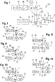
- Fig. 25 and 26 show eighth and ninth embodiments of the transmission 110, each having a five link planetary gear set 117 similar to Fig. 14 to 17 , wherein the planetary gear set is a modified Ravigneaux gear set, with the first link 101 being a planet carrier, the second link 102 and the third link 103 being ring gears, the forth link 104 and the fifth link 105 being sun gears.
- the second link 102 and forth link 104 are meshed via a first row of planets, the third link 103 and the fifth link are meshed with a second row of planets, wherein the first and second rows of planets are intermeshed.
- the input shaft 112 of the transmission 110 is constantly connected to the first link 101 or engageable to the first link 101 of the five-link planetary gear set 117 via a switchable input clutch and/or a dual mass flywheel.
- At least one of the planet rows comprises double-mesh planets.
- the five-link gear set 117 comprises the row of planets with quad mesh, wherein the four meshes are meshed with first, second, third and fourth links 102, 102, 103, 104 correspondingly, and the fifth link 105 is connected to the planet carrier.
- the first, second, third and fourth links 102, 102, 103, 104 may be configures as sun gears or ring gears.
- the electric machine(s) 16, 116, 116a is (are) controlled by the control system 26, 126, 126a in a way that it allows to reduce torque value down to zero on either input shaft 20, 120, of the first sub-transmission 14, 114 or on the input shaft 22, 122 of the second sub-transmission 15, 115 by applying different levels of negative shaft power, while the transmission 10, 110 transfers the power from the input shaft 12, 112 to the output shaft 13, 113.
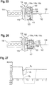
- Fig. 27 shows acceleration-time sequence plots of a passenger car at high speed and wide-open throttle operation of the internal combustion engine, wherein the accelerations a 1 , a 2 of a vehicle applying the inventive device and method is compared to the acceleration a 3 of a vehicle with a conventional automated mechanical transmission, during 4 to 5 gear shifting.
- the line a 1 indicates 60% torque fill
- the line a 2 indicates 100% torque fill during shifting.
- the plot shows clearly the improvement of the present invention, i.e., a considerable reduction of the torque decrease during gear shifting.
Abstract
Description
- The invention relates to a multi-speed transmission, especially for a vehicle, comprising a power split device, an input shaft being connected or connectable to a prime mover, an output shaft, two shiftable sub-transmissions, each providing a plurality of different gear ratios, and at least one rotating electric machine, connected to said power split device, wherein the two sub-transmissions can be connected alternatively to the output shaft, and a control system connecting said electric machine with an electric battery and auxiliary electrical consumers. Further the invention relates to a method for operating such a multi-speed transmission.
- The document
US 8,771,139 B2 describes a power transmission unit with an engine and a plurality of speed change gear pairs, each of which has a different gear ratio, and to which a power outputted from the engine is transmitted. The power transmission unit comprises a differential mechanism, which has three rotary elements performing a differential action, and in which a first rotary element is connected with the engine. An electric motor is connected with a secondary rotary element of the three rotary elements. The plurality of speed change gear pairs include a first gear pair connected with the first rotary element and the output member, and a second gear pair connected with a third rotary element of the three rotary elements and the output member. - The
U.S. patent No. 7,575,529 B2 describes an electrically variable transmission, wherein the transmission provides electrically variable power flow along dual power paths and provides an electrically variable reverse operating mode. The transmission includes a compound differential gear set having at least four gear elements operatively interconnected with one another. A transmission input member and the single motor/generator selectively provide power to a transmission output member via the differential gear set. The transmission includes a plurality of intermeshing gears, including a reverse gear and gears connected for rotation with the output member, for operatively connecting the differential gear set with the output member. Torque-transmitting mechanisms are selectively engageable to provide power flow between the input member and the output member in multiple operating modes, including a parallel hybrid electrically variable operating mode utilizing the reversing gear. - Electric motor/generators of known hybrid transmissions are constituted for four quadrant operation with high positive and negative shaft power, which is comparable to the engine power. The motor/generators have to be designed large-sized, the control of the motor/generators is complex and expensive.
- It is the object of the present invention to avoid these disadvantages and to provide a compact and low priced multi-speed transmission. It is a further object of the invention to enable a reduction of the torque decrease during gear shifting.
- According to the present invention this is achieved in that the electric machine is connected to the power split device and controlled by the control systems in a way that it allows to reduce torque value down to zero on either the input shaft of the first sub-transmission or on the input shaft of the second sub-transmission by applying different shaft torque levels and the internal heat generation capacity of the electric machine exceeds the power capacity of the power line in said control system.
- In comparison to prior art embodiments the power electronics and the battery can be designed with reduced capacity. The electric machine can be designed smaller. This enables lower cost, weight and package. In contrast to conventional AMTs (Automated Manual Transmission) design can be carried out without any friction clutches and synchronizers.
- The transmission according to the present invention has torque fill capacity. This means that torque reduction during shift operations can be compensated at least partly. Thereby the electric machine is controlled by the control system in a way that it allows to reduce torque value down to zero on either input shaft of the first sub-transmission, or on the input shaft of the second sub-transmission, by applying positive or negative power. The positive power is taken from the battery. A fraction of negative power, which does not exceed instant power consumption from the battery with auxiliary electrical consumers, is delivered to the battery and to auxiliary electrical consumers. A residual fraction of negative power is dissipated in the electric machine as heat.
- The electric machine provides torque reaction and supplies the electric power at the same time, converting a fraction of the shifting losses to electric energy. The power capacity of the control system is several times smaller than for conventional hybrid transmissions with torque-filled shifts.
- The fraction of heat dissipation is at least 50%.
- In well-known hybrid transmissions the efficiency of the electric drives in hybrid powertrain is above 85% to 90%, wherein 10% to 15% of the energy is dissipated in the electric machine and the control system. For the invention, preferably 95% to 99% should be dissipated, in order to avoid expensive electronics and large battery. In practice, the fraction of heat dissipation may lie in the range between 50% and 99%.
- According to a preferred embodiment of the invention the connections of the power split device, and the combination of gear ratios of the power split device and the sub-transmissions allow to reduce torque value down to zero on either the input shaft of the first sub-transmission or on the input shaft of the second sub-transmission by applying only negative shaft power to the electric machine, while the transmission transfers the power from the input shaft to the output shaft. Lowest cost, weight and package can be realized, when the control system of the electric machine and/or the electric machine is limited solely to negative shaft power operation of the electric machine, so the electric machine can be operated solely with negative shaft power. Designing the electric machine with positive power operations can be neglected. This design would enable a smaller electric machine. Further a reduced capacity of the power electronics and the battery would enable lower cost, weight and package as well as a very compact and small layout of the electric machine, saving costs and weight.
- However, there is an opportunity to select gear ratios in such a way, that in some modes a small positive power is required from the electric machine for torque split, i.e. when the rotor speed is reversed. This small power is below peak capacity of the control system.
- Therefore the power capacity of the electric machine control system should be limited just to provide engine starter function, power supply function to charge conventional low-voltage battery and to synchronize shaft speeds in the sub-transmission during gear changing in the sub-transmission when it does not transmit the power flow. For typical applications the power capacity of the electric machine control system should be from 1% to 5% of the engine rated power.
- During torque-filled gearshifts a relatively high level of negative power should be applied to the shaft of the electric machine, up to 50% of the engine power. To avoid overload of the control system, a major fraction of that negative power should be dissipated in the inductor of the electric machine as heat power. In a preferred embodiment the armature of the electric machine is a stator with coils, which are connected to AC inverter, and the inductor is a rotor with a squirrel cage. In another possible embodiment the inductor is a stator with squirrel cage, and the armature is a rotor with coils, which are connected to AC inverter via sliding brushes and contact rings.
- The required heat generation capacity of the electric machine can be provided by heat capacity of the rotor and natural air cooling, forced air cooling of the rotor or forced liquid cooling of the rotor.
- In engine start, power supply and shaft synchronizing modes the electric machine operates like state-of-the-art induction inverter-fed machines. During torque-filled gearshifts it operates in generating mode with higher slip ratio than conventional electric machines. A large fraction of shaft power is dissipated in the squirrel cage. For light-duty applications heat capacity of the squirrel cage and the surrounding core can be used to absorb heat energy during torque-filled shifts. For heavy-duty applications forced cooling of the inductor may be implemented (e.g. liquid cooling)
- The inventive transmission and method can be used for gear disengagement, shaft speed synchronization and gear engagement in that sub-transmission which is unloaded by the torque reduction, wherein friction clutches can be avoided.
- Further it can be used for launching the vehicle with the transmission. Precise launch control may be provided without using of any master clutch or torque converter.
- Further it can be used for braking the vehicle with the transmission. This function may replace conventional transmission retarder (e.g. hydrodynamic or eddy-current) in heavy-duty applications. Forced liquid cooling of the rotor is required for this function.
- The multi-speed transmission according to the present invention can also be used for starting the engine up, in the way that power is taken from the battery and delivered to a crankshaft for cranking. The power capacity of the power line in the control system need not exceed the power needed for engine cranking with electric machine.
- Synchronizers can be eliminated when the electric machine is used for changing the speed of the input shaft of the one of the sub-transmissions, when this sub-transmission does not transmit the power flow, wherein this speed changing is done independently on the engine speed.
- In a low cost and simplest design embodiment of the power split device there is provided that the power split device is a three-link planetary gear set, with a first link, a second link and a third link. Such design may be used in the transmission with partial torque fill. In a first layout of this embodiment it is provided that the input shaft of the transmission is engageable to the first link, the input shaft of the first sub-transmission is engageable to the first link, the input shaft of the second sub-transmission is connected to the third link, and the electric machine is connected to the second link of said three-link planetary gear set, wherein preferably the speed ratio between the second link and the third link is negative for stopped first link. In a second layout of this low cost embodiment it is provided that the input shaft of the transmission is engageable to the third link, the input shaft of the first sub-transmission is connected to the first link, the input shaft of the second sub-transmission is engageable to the third link, and the electric machine is connected to the second link of said gear set, wherein preferably the speed ratio between the second link and the third link is negative for stopped first. These low cost embodiments can be designed without any friction clutches and synchronizers, wherein full torque fill capacity is provided.
- When the electric machine is locked, speed reduction is provided from the transmission input shaft to the input shaft of the first sub-transmission, increasing overall gear ratio of the transmission.
- In simple and low cost embodiments with a reduced number of components the input shaft of the transmission and/or the first sub-transmission are constantly connected to the first link. Alternatively, especially for hybrid applications, the input shaft of the transmission may be engageable to the first link via an input clutch. For high-performance applications with demand for higher rate of torque fill the input shaft of the first sub-transmission can be engaged to the first link via an intermediate clutch, for example a friction clutch.
- Further for low cost applications the transmission additionally may include a lock-up clutch for locking the power split, for example arranged between the first and the third link. With this optional lock-up clutch additional gears may be provided by double use of the second sub-transmission.
- In an advanced embodiment of the present invention it is provided that the input shaft of the transmission is engageable to the first link via a first clutch and to the third link via a third clutch, the input shaft of the first sub-transmission is engageable to the first link via a second clutch and to the third link via a forth clutch, the input shaft of the second sub-transmission is connected to the input shaft, and the electric machine is connected to the second link of said gear set, wherein preferably the speed ratio between the second link and the third link is negative for stopped first link. Therefore with selective connection of the combustion engine and the first sub-transmission more gears are available or torque fill capacity is improved. At least one of said first, second, third and fourth clutches may be embodied as a dog clutch.
- In each of said embodiment described above the first link may be a planet carrier, the second link a sun gear and the third link a ring gear. This connection gives the internal ratio of -1.4 to -4, providing possible transmission gear step of 1.25 to 1.7.
- In a further embodiments of the invention it is provided that the power split device is a five-link planetary gear set, with a first link, a second link, a third link, a fourth link and a fifth link, wherein preferably the input shaft of the transmission is engageable to the first link, the input shaft of the first sub-transmission is connected to the second link, the input shaft of the second sub-transmission is connected to the third link, and a first electric machine is engageable to the forth link of said gear set. In an advantageous embodiment of the present invention it is provided that the speed ratio between the second link and the third link is negative for stopped first link, the speed ratio between the forth link and the fifth link is negative for stopped first link, the speed ratio of the forth link to the second link is more than one for stopped first link, and the speed ratio of fifth link to the third link is more than one for stopped first link. The five-link power split device either provides twice more gears or improves torque fill capability with the same number of gearwheels and shifting elements in sub-transmissions.
- More preferably the transmission additionally comprises a second electric machine, which is connected to the fifth link, and the first electric machine is constantly connected to the forth link. In order to reduce costs unified electric machines and power electronics can be used. Optionally eCVT (electronic continuous variable transmission) - capability at small loads and speeds can be used. Alternatively the transmission additionally comprises an electric brake, which is connected to the fifth link, and the first electric machine is constantly connected to the forth link. For the electric brake a simple DC converter can be used instead of an AC inverter. One electric machine - the first electric machine - is enough to provide starter and alternator functions. Preferably the electric brake is embodied as an eddy current brake. But also other electric brakes may be used.
- Alternatively to an electric brake the transmission may comprise a friction brake, which is connected to the fifth link, and wherein the first electric machine is constantly connected to the forth link.
- The first electric machine may be engageable to the fourth link via a first selection clutch and to the fifth link via a second selection clutch. In this way the fourth and/or fifth links can be connected to a single electric machine, i.e., the first electric machine. Using a single electric machine has the advantage that costs and weights can be reduced. In a very simple embodiment the first and/or second selection clutches may be designed as dog clutches. Further the transmission additionally may comprise a controllable brake, for example a simple dog brake, connecting the fifth link to a transmission housing. The brake may provide one or two additional gears.
- In a further embodiment of five-link power split device it is provided that the five-link planetary gear set is a modified Ravigneaux gear set, wherein preferably the first link is a planet carrier, the second and the third links are ring gears, the forth and the fifth links are sun gears, the second and forth links are meshed via first row of planets, the third and fifth links are meshed with second row of planets and said first and second rows of planets are intermeshed. At least one of the rows of planets may comprise double mesh planets. Alternatively the five-link planetary gear set may comprise the row of planets with quad mesh, wherein the four meshes are meshed with the first, second, third and fourth links correspondingly, and wherein the fifth link is connected to planet carrier. The first, second, third and fourth links may be sun gears or ring gears.
- In each embodiment of the five-link power split devices the input shaft may be connected to the first link constantly. A fixed connection between input shaft and first link is suitable for low-cost applications with a reduced number of components. Alternatively - especially for hybrid applications, enabling an E-Drive mode - the input shaft may be engageable to the first link via an input clutch.
- In connection with the present invention the transmission additionally may include a plurality of control elements, which interconnect the links of said sub-transmissions to transfer the power flow, wherein at least one of the control elements can be configured as a dog clutch. At least one of said sub-transmissions may be designed as a two-shaft gearbox with parallel input and output shafts or as a three-shaft gearbox with parallel input and two output shafts, both output shafts constantly meshing with a final gear. Alternatively at least one of said sub-transmissions may be a three-shaft gearbox with coaxial input and output shafts, wherein preferably one of the gear is a direct gear. More alternatively at least one of said sub-transmissions may be a planetary gearbox, with preferably one of the gear being a direct gear. A direct gear has the advantage of best efficiency.
- The invention is explained below in closer detail by reference to the drawings, wherein:
- Fig. 1
- is a schematic illustration of a multi speed transmission with a three link power split device in accordance with a first embodiment of invention;
- Fig. 2
- schematically shows this transmission in a first operating state;
- Fig. 3
- schematically shows this transmission in a second operating state;
- Fig. 4
- schematically shows this transmission in a third operating state;
- Fig. 5
- schematically shows this transmission in a fourth operating state;
- Fig. 6
- schematically shows this transmission in a fifth operating state;
- Fig. 7
- is a schematic illustration of a multi speed transmission with a three link power split device in accordance with a second embodiment of the invention;
- Fig. 8
- schematically shows this transmission in a first operating state;
- Fig. 9
- schematically shows this transmission in a second operating state;
- Fig. 10
- schematically shows this transmission in a third operating state;
- Fig. 11
- schematically shows this transmission in a fourth operating state;
- Fig. 12
- schematically shows this transmission in a fifth operating state;
- Fig. 13
- is a schematic illustration of a multi speed transmission with a five link power split device in accordance with a third embodiment of the invention;
- Fig. 14
- is a schematic illustration of a multi speed transmission with a five link power split device in accordance with a forth embodiment of the invention;
- Fig. 15
- is a schematic illustration of a multi speed transmission with a five link power split device in accordance with a fifth embodiment of the invention;
- Fig. 16
- is a schematic illustration of a multi speed transmission with a five link power split device in accordance with a sixth embodiment of the invention;
- Fig. 17
- is a schematic illustration of a multi speed transmission with a five link power split device in accordance with a seventh embodiment of the invention;
- Fig. 18
- schematically shows a transmission with a five link power split device in a first operating state;
- Fig. 19
- schematically shows a transmission with a five link power split device in a second operating state;
- Fig. 20
- schematically shows a transmission with a five link power split device in a third operating state;
- Fig. 21
- schematically shows a transmission with a five link power split device in a fourth operating state;
- Fig. 22
- schematically shows a transmission with a five link power split device in a fifth operating state;
- Fig. 23
- schematically shows a transmission with a five link power split device in a sixth operating state;
- Fig. 24
- schematically shows a transmission with a five link power split device in a seventh operating state;
- Fig. 25
- is a schematic illustration of a multi speed transmission with a five link power split device in accordance with an eight embodiment of the invention;
- Fig. 26
- is a schematic illustration of a multi speed transmission with a five link power split device in accordance with a ninth embodiment of the invention; and
- Fig. 27
- show acceleration-time sequence plots of a passenger car during gearshifts applying the inventive method.
-
Figs. 1 to 13 each showmulti speed transmissions 10 for a vehicle comprising apower split device 11, aninput shaft 12, anoutput shaft 13, a firstshiftable sub-transmission 14 and a secondshiftable sub-transmission 15, wherein each of thesub transmissions transmission 10 further comprises a rotatingelectric machine 16, connected to thepower split device 11. Theelectric machine 16, e.g., is a multi-phase induction machine with squirrel cage inductor. According to a brushless variant the inductor is a movable rotor, the armature is a fixed stator, and the windings of the armature are connected to the multi-phase bi-directional AC/DC power inverter via fixed electrical connection. Better cooling conditions are available with an immovable inductor being designed as a fixed stator; the armature is a movable rotor, and the windings of the armature are electrically connected to the multi-phase bi-directional AC/DC power inverter via sliding contact of brushes and rings. The inductor is capable of dissipating full mechanical brake power. The inductor may comprise means for forced cooling, e.g. at least one cooling passage for liquid cooling. The two sub-transmissions 14, 15 can be connected alternatively to theoutput shaft 13. Theelectric machine 16 is electrically connected to acontrol system 26 and abattery 27, e.g., a low-voltage battery. Thecontrol system 26 of theelectric machine 16 may comprise a multi-phase bi-directional AC/DC power inverter. The braking power capacity of theelectric machine 16 exceeds the power capacity of the multi-phase bi-directional AC/DC converter. The internal heat dissipation power of theelectric machine 16 is higher than the electric power flow through thecontrol system 26 of theelectric machine 16. Each of theFigs. 1 ,7 and13 shows embodiments withpower split devices 11 each of them being configured as a three-link planetary gear sets 17 withfirst links 1,second links 2 andthird links 3. Theinput shaft 12 of thetransmission 10 is connected to aprime mover 18, e.g. an internal combustion engine. In the first embodiment shown inFig. 1 to 6 theinput shaft 12 of thetransmission 10 is engaged to thefirst link 1 or engageable to thefirst link 1 of the planetary gear set 17 via aswitchable input clutch 19. In the second embodiment shown inFig. 7 to 12 theinput shaft 12 of thetransmission 10 is engaged to thethird link 3 or engageable to thefirst link 3 of the planetary gear set 17 via a switchable first clutch 19. Theinput shaft 20 of thefirst sub-transmission 14 is engaged to thefirst link 1 or engageable to thefirst link 1 via aswitchable clutch 21. Theinput shaft 22 of thesecond sub-transmission 15 is connected to thethird link 3. Theelectric machine 16 is connected to thesecond link 2 of the planetary gear set 17, wherein the speed ratio between thesecond link 2 and thethird link 3 is negative for stoppedfirst link 1. - For example, the
first link 1 may be a planet carrier, the second link 2 a sun gear and the third link 3 a ring gear. This connection enables an internal ratio of -1.4 to -4, providing possible transmission gear steps of 1.25 to 1.7. - Optionally an input clutch 19 can be arranged between the
prime mover 18 and theplanetary gear 17. Theinput shaft 12 of thetransmission 10 is engageable to the first link 1 (Figs. 1 to 6 ) or the third link 3 (Figs. 7 to 12 ), respectively, via theinput clutch 19. This connection, e.g. for hybrid applications, enables electric drive modes of the vehicle. Alternatively, for low-cost applications with a reduced number of components, theinput shaft 12 of thetransmission 10 may be constantly connected to thefirst link 1. - Further optionally an intermediate clutch 21 can be arranged between the
first link 1 and theinput shaft 20 of the first sub-transmission 14 (Figs. 1 to 6 ) or between thethird link 3 and theinput shaft 20 of the second sub-transmission 15 (Figs. 7 to 12 ), respectively. This enables high performance and a higher rate of torque fill. For low cost applications with reduced number of components alternatively thefirst sub-transmission 14 orsecond sub-transmission 15, respectively, may be constantly connected to thefirst link 1. - With an optional lockup clutch 23 between the first and the
third links optional interconnections 24 may be arranged between first and second sub-transmissions 14, 15. - The
Figs. 8 to 10 show variations in operation of the planetary gear set 17 of the second embodiment of thetransmission 10 shown inFig. 7. Fig. 8 shows a moving-off situation of the vehicle using thefirst sub-transmission 14, wherein theprime mover 18 drives theinput shaft 12. Theelectric machine 16 is rotating with negative torque while brakingpower 25 of theelectric machine 16 is dissipated.Fig. 9 shows a similar situation with increasing negative torque of the rotatingelectric machine 16. The speed n3 of thethird link 3 is much larger than the speed n1 of the first link 1: n3>>n1.Fig. 10 shows an operating situation with stopped firstelectric machine 16, and with n3>n1. -
Figs. 11 and 12 show the torque distribution control by the firstelectric machine 16. InFig. 11 controlled by the firstelectric machine 16 zero torque is applied to thefirst sub-transmission 14. So shifting is possible in thefirst sub-transmission 14. InFig. 12 theelectric machine 16 is operated with negative torque in a way that zero torque is applied to thesecond sub-transmission 15. So shifting is possible in thesecond sub-transmission 15. Torque fill is provided by thefirst sub-transmission 14. Theelectric machine 16 provides torque reaction and dissipates brakingpower 25. -
Fig. 13 shows a third embodiment of thetransmission 10, wherein theinput shaft 12 of thetransmission 10 is engageable to thefirst link 1 via a first input clutch 19a and to thethird link 3 via a second input clutch 19b. Theinput shaft 20 of thefirst sub-transmission 14 is engageable to thefirst link 1 via a first intermediate clutch 21a and to thethird link 3 via a second intermediate clutch 21b. Theinput shaft 22 of thesecond sub-transmission 15 is connected to theinput shaft 12 of thetransmission 10. Theclutches second link 2 andthird link 3 is negative for stoppedfirst link 1. - The third embodiment has the advantage that with selective connection of the
combustion engine 18 and the first sub-transmissions 14 more gears are available or torque fill capacity is improved. As described above, for example thefirst link 1 may be a planet carrier, the second link 2 a sun gear and the third link 3 a ring gear. This connection enables an internal ratio of -1.4 to -4, providing possible transmission gear steps of 1.25 to 1.7. -
Figs. 14 to 17 each showmulti speed transmissions 110 for a vehicle comprising apower split device 111, aninput shaft 112, anoutput shaft 113, a firstshiftable sub-transmission 114 and a secondshiftable sub transmission 115, wherein each of thesub transmissions transmission 110 further comprises a rotating firstelectric machine 116, connected to thepower split device 111. The twosub-transmissions output shaft 113. The firstelectric machine 116 is electrically connected to acontrol system 126 and abattery 127.Electric machine 116,control system 126 andbattery 127 are similar to the aforesaid embodiments. Each of theFigs. 14 to 17 shows embodiments with power splitdevices 111 each of them being configured as a five-link planetary gear sets 117 withfirst links 105,second links 102,third links 103, fort links 104 andfifth links 105. Theinput shaft 112 of thetransmission 110 is connected to aprime mover 118, e.g. an internal combustion engine. Theinput shaft 112 of thetransmission 110 is engaged to thefirst link 101 or engageable to thefirst link 101 of the five-link planetary gear set 117 via aswitchable input clutch 119. Theinput shaft 120 of thefirst sub-transmission 114 is engaged to thesecond link 102. Theinput shaft 122 of thesecond sub-transmission 115 is connected to thethird link 103. The firstelectric machine 116 is connected to the forth link 104 of the five link planetary gear set 117, wherein the speed ratio between thesecond link 102 and thethird link 103 is negative for stoppedfirst link 101, the speed ratio between theforth link 104 and thefifth link 105 is negative for stoppedfirst link 101, the speed ratio offorth link 104 tosecond link 102 is more than one for stopped first link 101 and the speed ratio offifth link 105 tothird link 103 is more than one for stoppedfirst link 101. - With an optional lockup clutch 123 between the
first link 101 and thesecond link 102 of the planetary gear set 117 thefirst link 101 and thesecond link 102 can be locked. - In the fourth embodiment of the
transmission 110 shown inFig. 14 thetransmission 110 additionally comprises asecond machine 116a, which is connected to thefifth link 105 of the five-link planetary gear set 117. The secondelectric machine 116a is electrically connected to asecond control system 126a and thebattery 127. Power electronics andelectric machines electric machines -
Fig. 15 shows an fifth embodiment of thetransmission 110 similar toFig. 14 , wherein the secondelectric machine 116a is replaced by anelectric brake 116b, which is connected to thefifth link 105 of the five-link planetary gear set 117. Theelectric brake 116b is electrically connected to asecond control system 126b, e.g., a DC converter, and thebattery 127. A DC-converter of an electric brake is much simpler than an AC-inverter of an electric machine. For example theelectric brake 116b is an eddy current brake. Of course other types of electric brakes are possible, too. - Alternatively to a
second machine 116a or anelectric brake 116b, thetransmission 110 additionally may comprise afriction brake 116c, which is connected to thefifth link 105 of the five-link planetary gear set 117. A sixth embodiment including such afriction brake 116c is shown inFig. 16 . Friction brakes save costs and package. The firstelectric machine 116a is sufficient to provide starter and alternator functions. -
Fig. 17 shows a seventh embodiment of atransmission 110 with a five link planetary gear set 117 similar toFig. 14 to 16 , wherein theelectric machine 116 is engageable to the forth link 104 of the planetary gear set 117 via afirst selection clutch 128 and to thefifth link 105 of the planetary gear set 117 via asecond selection clutch 129. The singleelectric machine 116 reduces costs and weight. As indicated inFig. 17 by broken lines, thetransmission 110 additionally may comprise acontrollable brake 130 in order to provide one or two additional gears. According to a variant with very simple design thefirst selection clutch 128, thesecond selection clutch 129 and/or thebrake 130 are configured as dog clutches. - The
Figs. 18 to 24 show variations in operation of a five-link planetary gear set 117 of the embodiment shown inFig. 14 . ButFigs. 18 to 24 may also apply to embodiments shown inFigs. 15 to 17 withelectric brakes 116b orfriction brakes 116c instead of thesecond machine 116a. -
Fig. 18 shows a moving-off situation of the vehicle using thefirst sub-transmission 114, wherein theprime mover 118 drives theinput shaft 112. The firstelectric machine 116 is wind milling; the secondelectric machine 116a is rotating with negative torque while brakingpower 125 of the secondelectric machine 116a is dissipated.Fig. 19 shows a similar acceleration situation with thefourth link 104 being stopped by the firstelectric machine 116. The speed n103 of thethird link 103 is larger than the speed n102 of thesecond link 102.Fig. 20 shows an operating situation with stopped fifth link 105 by the secondelectric machine 116a, wherein the speed n102 of thesecond link 102 is larger than the speed n103 of the third link 103: n102>n103.Fig. 21 shows a moving-off situation of the vehicle using thesecond sub-transmission 115, wherein the secondelectric machine 116a is wind milling and the firstelectric machine 116 is rotating with negative torque while brakingpower 125 of the firstelectric machine 116 is dissipated. -
Fig. 22 to 24 show the torque distribution control by the firstelectric machines Fig. 22 controlled by the firstelectric machine 116 zero torque is applied to thefirst sub-transmission 114. So shifting is possible in thefirst sub-transmission 114. InFig. 23 torque is split betweenfirst sub-transmission 114 andsecond sub-transmission 115. No torque reaction happens at theforth link 104 and thefifth link 105 of the planetary gear set 117.Fig. 24 shows a situation wherein controlled by the secondelectric machine 116a a zero torque is applied to thesecond sub-transmission 115. So shifting is possible in thesecond sub-transmission 115. -
Fig. 25 and 26 show eighth and ninth embodiments of thetransmission 110, each having a five link planetary gear set 117 similar toFig. 14 to 17 , wherein the planetary gear set is a modified Ravigneaux gear set, with thefirst link 101 being a planet carrier, thesecond link 102 and thethird link 103 being ring gears, the forth link 104 and thefifth link 105 being sun gears. Thesecond link 102 and forth link 104 are meshed via a first row of planets, thethird link 103 and the fifth link are meshed with a second row of planets, wherein the first and second rows of planets are intermeshed. Theinput shaft 112 of thetransmission 110 is constantly connected to thefirst link 101 or engageable to thefirst link 101 of the five-link planetary gear set 117 via a switchable input clutch and/or a dual mass flywheel. - In the eight embodiment shown in
Fig. 25 at least one of the planet rows comprises double-mesh planets. - In the ninth embodiment shown in
Fig. 26 the five-link gear set 117 comprises the row of planets with quad mesh, wherein the four meshes are meshed with first, second, third andfourth links fifth link 105 is connected to the planet carrier. The first, second, third andfourth links - In each embodiment the electric machine(s) 16, 116, 116a is (are) controlled by the
control system input shaft first sub-transmission input shaft second sub-transmission transmission input shaft output shaft -
Fig. 27 shows acceleration-time sequence plots of a passenger car at high speed and wide-open throttle operation of the internal combustion engine, wherein the accelerations a1, a2 of a vehicle applying the inventive device and method is compared to the acceleration a3 of a vehicle with a conventional automated mechanical transmission, during 4 to 5 gear shifting. The line a1 indicates 60% torque fill, the line a2 indicates 100% torque fill during shifting. The plot shows clearly the improvement of the present invention, i.e., a considerable reduction of the torque decrease during gear shifting.
Claims (15)
- A multi-speed transmission (10, 110) especially for a vehicle, comprising a power split device (11; 111), an input shaft (12, 112) being connected or connectable to a prime mover (18, 118), an output shaft (13; 113), two shiftable sub-transmissions (14, 114; 15, 115), each providing a plurality of different gear ratios, and at least one rotating electric machine (16; 116, 116a), connected to said power split device (11; 111), wherein the two sub-transmissions (14, 114; 15, 115) can be connected alternatively to the output shaft (13, 113), and a control system (26; 126, 126a), connecting aid electric machine (16; 116, 116a) with an electric battery (27; 127) and auxiliary electrical consumers (31, 131), characterised in that the electric machine (16; 116, 116a) is connected to the power split device (11; 111) in a way that it allows to reduce torque value down to zero on either the input shaft (20; 120) of the first sub-transmission (14; 114) or on the input shaft (22; 122) of the second sub-transmission (15; 115) by applying different shaft torque levels, and the internal heat generation capacity of the electric machine (16; 116, 116a) exceeds the power capacity of the power line in said control system (26; 126, 126a).
- The transmission (110) according to claim 1, characterised in that the connections of the power split device, and the combination of gear ratios of the power split device and the sub-transmissions allow to reduce torque value down to zero on either the input shaft (20; 120) of the first sub-transmission (14; 114) or on the input shaft (22; 122) of the second sub-transmission (15; 115) by applying only negative shaft power to the electric machine while the transmission (10; 110) transfers the power from the input shaft (12; 112) to the output shaft (13; 113).
- The transmission (10) according to claim 1 or 2, characterised in that the power split device (11) is a three-link planetary gear set (17), with a first link (1), a second link (2) and a third link (3), wherein the input shaft (12) of the transmission (10) is engaged or engageable to the first link (1), the input shaft (20) of the first sub-transmission (14) is engaged or engageable to the first link (1), the input shaft (22) of the second sub-transmission (15) is connected to the third link (3), and the electric machine (16) is connected to the second link (2) of said three-link planetary gear set (17), wherein the speed ratio between the second link (2) and the third link (3) is negative for stopped first link (1). (Figs. 1 to 6)
- The transmission (10) according to claim 1 or 2, characterised in that the power split device (11) is a three-link planetary gear set (17), with a first link (1), a second link (2) and a third link (3, wherein) the input shaft (12) of the transmission (10) is engaged or engageable to the third link (3), the input shaft (20) of the first sub-transmission (14) is connected to the first link (1), the input shaft (22) of the second sub-transmission (15) is engageable to the third link (3), and the electric machine (16) is connected to the second link (2) of said three-link planetary gear set (17), wherein the speed ratio between the second link (2) and the third link (3) is negative for stopped first link (1). (Figs. 7 to 10)
- The transmission (10) according to claim 1 or 2, characterised in that the power split device (11) is a three-link planetary gear set (17), with a first link (1), a second link (2) and a third link (3, wherein) the input shaft (12) of the transmission (10) is engageable to the first link (1) via a first input clutch (19a) and to the third link (3) via a second input clutch (19b), the input shaft (20) of the first sub-transmission (14) is engageable to the first link (1) via a first intermediate clutch (21a) and to the third link (3) via a second intermediate clutch (21b), the input shaft (22) of the second sub-transmission (15) is connected to the input shaft (12) of the transmission (10), and the electric machine (16) is connected to the second link (2) of said three-link planetary gear set (17), wherein preferably the speed ratio between the second link (2) and the third link (3) is negative for stopped first link (1). (Fig. 13)
- The transmission (110) according to claim 1 or 2, characterised in that the power split device (111) is a five-link planetary gear set (117), with a first link (101), a second link (102), a third link (103), a fourth link (104) and a fifth link (105), wherein the input shaft (112) of the transmission (110) is engageable to the first link (101), the input shaft (120) of the first sub-transmission (114) is connected to the second link (102), the input shaft (122) of the second sub-transmission (115) is connected to the third link (103), and a first electric machine (116) is engageable to the fourth link (104) of said five-link planetary gear set (117), wherein preferably the speed ratio between the second link (102) and the third link (103) is negative for stopped first link (101), the speed ratio between the forth link (104) and the fifth link (105) is negative for stopped first link (101), the speed ratio of the forth link (104) to the second link (102) is more than one for stopped first link (101), and the speed ratio of the fifth link (105) to the third link (103) is more than one for stopped first link (101). (Fig. 14 to 26)
- The transmission (110) according to claim 6, characterised in that it additionally comprises a second electric machine (116a), which is connected to the fifth link (105), and the first electric machine (116) is constantly connected to the forth link (104). (Fig. 14)
- The transmission (110) according to claim 6, characterised in that it additionally comprises an electric brake (116b), which is connected to the fifth link (105), and the first electric machine (116) is constantly connected to the forth link (104), wherein preferably the electric brake (116b) is embodied as an eddy current brake. (Fig. 15)
- The transmission (110) according to claim 6, characterised in that it additionally comprises a friction brake (116c), which is connected to the fifth link (105), and the first electric machine (116) is constantly connected to the fourth link (104). (Fig. 16)
- The transmission (110) according to claim 6, characterised in that the first electric machine (116) is engageable to the fourth link (104) via a first selection clutch (128) and to the fifth link (105) via a second selection clutch (129), wherein preferably at least one of the first and second selection clutches (128, 129) is configured as a dog clutch. (Fig. 17)
- The transmission (110) according to claim 6, characterised in that the five-link planetary gear set (117) is a modified Ravigneaux gear set, wherein preferably the first link (101) is a planet carrier, the second and the third links (102, 103) are ring gears, the forth and the fifth links (104, 105) are sun gears, the second and forth links (102, 104) are meshed via a first row of planets, the third and fifth links (103, 105) are meshed with a second row of planets and said first and second rows of planets are intermeshed. (Fig. 25, 26)
- The transmission (110) according to claim 11, characterised in that the five-link planetary gear set (117) comprises the row of planets with quad mesh, said four meshes being meshed with first second third and fourth links correspondingly, and the fifth link (105) being connected to the planet carrier. (Fig. 26)
- Method for operating a multi-speed transmission (10; 110) of a vehicle, comprising a power split device (11; 111), an input shaft (12; 112) being connected or connectable to prime mover (18, 118), an output shaft (13;113), two shiftable sub-transmissions (14, 15; 114, 115), each providing a plurality of different gear ratios, and at least one rotating electric machine (16; 116, 116a), connected to said power split device (11; 111), wherein the two sub-transmissions (14, 15; 114, 115) are connected alternatively to the output shaft (13; 113), and wherein said electric machine (16; 116, 116a) is controlled by a control system (26; 126, 126a), characterised in that the electric machine (16; 116, 116a) is controlled by the control system (26; 126, 126a) in a way that it allows to reduce torque value down to zero on either input shaft (20; 120) of the first sub-transmission (14; 114) or on the input shaft (22; 122) of the second sub-transmission (15; 115) by applying positive or negative power, wherein the positive power is taken from the battery, and a fraction of negative power, which does not exceed instant power consumption from the battery with auxiliary electrical consumers, is delivered to the battery and to auxiliary electrical consumers, and wherein the residual fraction of negative power is dissipated in the electric machine (16; 116, 116a) as heat..
- The method according to claim 13, characterised in that the connections of the power split device, and the combination of gear ratios of the power split device and the sub-transmissions allow to reduce torque value down to zero on either the input shaft (20; 120) of the first sub-transmission (14; 114) or on the input shaft (22; 122) of the second sub-transmission (15; 115) by applying only negative shaft power to the electric machine while the transmission (10; 110) transfers the power from the input shaft (12; 112) to the output shaft (13; 113).
- The method according to claim 13 or 14, characterised in that the electric machine (16, 116, 116a) is used in at least one operation range of the vehicle as launch brake device, shift torque-filling brake device, transmission retarder brake device, shaft speed synchronizer, engine starter or alternator.
Priority Applications (4)
| Application Number | Priority Date | Filing Date | Title |
|---|---|---|---|
| EP14196899.0A EP3031648B1 (en) | 2014-12-09 | 2014-12-09 | Multi-speed transmission and method for operating the same |
| US15/533,254 US10358025B2 (en) | 2014-12-09 | 2015-12-09 | Multi-speed transmission and method for operating the same |
| CN201580066740.8A CN107107731B (en) | 2014-12-09 | 2015-12-09 | Multi-speed transmission and its operating method |
| PCT/EP2015/079090 WO2016091934A1 (en) | 2014-12-09 | 2015-12-09 | Multi-speed transmission and method for operating the same |
Applications Claiming Priority (1)
| Application Number | Priority Date | Filing Date | Title |
|---|---|---|---|
| EP14196899.0A EP3031648B1 (en) | 2014-12-09 | 2014-12-09 | Multi-speed transmission and method for operating the same |
Publications (2)
| Publication Number | Publication Date |
|---|---|
| EP3031648A1 true EP3031648A1 (en) | 2016-06-15 |
| EP3031648B1 EP3031648B1 (en) | 2018-02-07 |
Family
ID=52101076
Family Applications (1)
| Application Number | Title | Priority Date | Filing Date |
|---|---|---|---|
| EP14196899.0A Active EP3031648B1 (en) | 2014-12-09 | 2014-12-09 | Multi-speed transmission and method for operating the same |
Country Status (4)
| Country | Link |
|---|---|
| US (1) | US10358025B2 (en) |
| EP (1) | EP3031648B1 (en) |
| CN (1) | CN107107731B (en) |
| WO (1) | WO2016091934A1 (en) |
Cited By (3)
| Publication number | Priority date | Publication date | Assignee | Title |
|---|---|---|---|---|
| EP3261233A1 (en) | 2016-06-22 | 2017-12-27 | AVL List GmbH | Powertrain for a vehicle |
| WO2018077457A1 (en) * | 2016-10-27 | 2018-05-03 | Daimler Ag | Hybrid drive device |
| EP3363671A1 (en) * | 2017-02-16 | 2018-08-22 | AVL List GmbH | Multi-speed power shifted hybrid transmission and method for engine start |
Families Citing this family (4)
| Publication number | Priority date | Publication date | Assignee | Title |
|---|---|---|---|---|
| KR101688334B1 (en) * | 2015-12-29 | 2017-01-02 | 한국과학기술원 | A hybrid vehicle powertrain apparatus with multi-mode |
| US9969254B2 (en) * | 2016-05-27 | 2018-05-15 | GM Global Technology Operations LLC | Multi-state powertrain system including a single torque machine |
| DE102016008167B4 (en) * | 2016-07-02 | 2023-01-26 | Audi Ag | Drive device for a motor vehicle, motor vehicle with a drive device and method for operating a drive device |
| DE102019123367A1 (en) * | 2019-08-30 | 2021-03-04 | Knorr-Bremse Systeme für Nutzfahrzeuge GmbH | Powertrain for a vehicle |
Citations (4)
| Publication number | Priority date | Publication date | Assignee | Title |
|---|---|---|---|---|
| EP1247687A2 (en) * | 2001-04-04 | 2002-10-09 | Honda Giken Kogyo Kabushiki Kaisha | Control apparatus for electric motor and control apparatus for hybrid vehicle |
| US7575529B2 (en) | 2006-09-13 | 2009-08-18 | Gm Global Technology Operations, Inc. | Hybrid electrically variable transmission with geared reverse mode using single motor/generator |
| US20110111910A1 (en) * | 2008-06-03 | 2011-05-12 | Toyota Jidosha Kabushiki Kaisha | Vehicle drive system |
| US8771139B2 (en) | 2007-06-19 | 2014-07-08 | Toyota Jidosha Kabushiki Kaisha | Power transmission unit |
Family Cites Families (6)
| Publication number | Priority date | Publication date | Assignee | Title |
|---|---|---|---|---|
| JP4265570B2 (en) * | 2005-05-10 | 2009-05-20 | トヨタ自動車株式会社 | Power output device, automobile equipped with the same, drive device, and control method for power output device |
| US8292769B2 (en) * | 2006-11-22 | 2012-10-23 | Lawson Jr Thomas Towles | Transmission |
| US8771143B2 (en) * | 2008-03-31 | 2014-07-08 | Aisin Ai Co., Ltd. | Hybrid power drive system |
| JP4926209B2 (en) * | 2009-06-10 | 2012-05-09 | 本田技研工業株式会社 | Automatic transmission for hybrid vehicles |
| US8777789B2 (en) * | 2012-01-04 | 2014-07-15 | Zf Friedrichshafen Ag | Split axis transmission hybrid system architecture |
| US8579751B2 (en) * | 2012-01-26 | 2013-11-12 | GM Global Technology Operations LLC | Hybrid powertrain with layshaft transmission and electric torque converter and method of controlling same |
-
2014
- 2014-12-09 EP EP14196899.0A patent/EP3031648B1/en active Active
-
2015
- 2015-12-09 WO PCT/EP2015/079090 patent/WO2016091934A1/en active Application Filing
- 2015-12-09 US US15/533,254 patent/US10358025B2/en active Active
- 2015-12-09 CN CN201580066740.8A patent/CN107107731B/en active Active
Patent Citations (4)
| Publication number | Priority date | Publication date | Assignee | Title |
|---|---|---|---|---|
| EP1247687A2 (en) * | 2001-04-04 | 2002-10-09 | Honda Giken Kogyo Kabushiki Kaisha | Control apparatus for electric motor and control apparatus for hybrid vehicle |
| US7575529B2 (en) | 2006-09-13 | 2009-08-18 | Gm Global Technology Operations, Inc. | Hybrid electrically variable transmission with geared reverse mode using single motor/generator |
| US8771139B2 (en) | 2007-06-19 | 2014-07-08 | Toyota Jidosha Kabushiki Kaisha | Power transmission unit |
| US20110111910A1 (en) * | 2008-06-03 | 2011-05-12 | Toyota Jidosha Kabushiki Kaisha | Vehicle drive system |
Cited By (3)
| Publication number | Priority date | Publication date | Assignee | Title |
|---|---|---|---|---|
| EP3261233A1 (en) | 2016-06-22 | 2017-12-27 | AVL List GmbH | Powertrain for a vehicle |
| WO2018077457A1 (en) * | 2016-10-27 | 2018-05-03 | Daimler Ag | Hybrid drive device |
| EP3363671A1 (en) * | 2017-02-16 | 2018-08-22 | AVL List GmbH | Multi-speed power shifted hybrid transmission and method for engine start |
Also Published As
| Publication number | Publication date |
|---|---|
| WO2016091934A1 (en) | 2016-06-16 |
| US10358025B2 (en) | 2019-07-23 |
| US20170361696A1 (en) | 2017-12-21 |
| EP3031648B1 (en) | 2018-02-07 |
| CN107107731A (en) | 2017-08-29 |
| CN107107731B (en) | 2019-06-28 |
Similar Documents
| Publication | Publication Date | Title |
|---|---|---|
| EP3031648B1 (en) | Multi-speed transmission and method for operating the same | |
| RU2653723C2 (en) | Method of management of a hybrid power transmission for optimization of fuel consumption, vehicle and electronic device for hybrid power transmission control | |
| RU2653722C2 (en) | Method of management of a hybrid power transmission for optimization of torque moment of internal combustion engine, vehicle and electronic device for hybrid power transmission control | |
| KR101464151B1 (en) | Hybrid powertrain | |
| RU2653904C2 (en) | Method of management of a hybrid power transmission, vehicle and electronic device for hybrid power transmission control | |
| EP3106337B1 (en) | Multi-speed transmission | |
| US9254737B2 (en) | Hybrid drive for a vehicle | |
| US8579751B2 (en) | Hybrid powertrain with layshaft transmission and electric torque converter and method of controlling same | |
| RU2654850C2 (en) | Method of vehicle breakaway with hybrid transmission and a vehicle with the hybrid transmission | |
| RU2653346C2 (en) | Method of management of a hybrid power transmission, vehicle and electronic device for hybrid power transmission control | |
| RU2666486C2 (en) | Method of management of a hybrid power transmission, vehicle and electronic device for hybrid power transmission control | |
| RU2653332C2 (en) | Method of management of a hybrid power transmission for transfer switching without torque moment interruption, vehicle and electronic device for hybrid power transmission control | |
| CN107735600B (en) | Shift control device for hybrid vehicle | |
| EP3363671B1 (en) | Multi-speed power shifted hybrid transmission and method for engine start | |
| RU2655233C2 (en) | Method of management of a hybrid power transmission, vehicle and electronic device for hybrid power transmission control | |
| RU2653724C2 (en) | Method of management of a hybrid power transmission, vehicle and electronic device for hybrid power transmission control | |
| CN103807370A (en) | Automated electric manual transmission | |
| EP3261233A1 (en) | Powertrain for a vehicle | |
| CN111033084B (en) | Automatic transmission for a motor vehicle and method for shifting an automatic transmission | |
| KR101376071B1 (en) | Multi-speed transmission with an integrated electric motor | |
| RU2655576C2 (en) | Method of hybrid transmission management and a vehicle with the hybrid transmission | |
| EP3006243A1 (en) | Dual clutch transmission, hybrid vehicle and method for controlling a hybrid vehicle | |
| EP3061638A1 (en) | Multi-speed transmission and method for operating a multi-speed transmission | |
| CN113056627A (en) | Transmission device for vehicle | |
| EP3165791A1 (en) | Multi-speed torque filled transmission |
Legal Events
| Date | Code | Title | Description |
|---|---|---|---|
| PUAI | Public reference made under article 153(3) epc to a published international application that has entered the european phase |
Free format text: ORIGINAL CODE: 0009012 |
|
| 17P | Request for examination filed |
Effective date: 20151218 |
|
| AK | Designated contracting states |
Kind code of ref document: A1 Designated state(s): AL AT BE BG CH CY CZ DE DK EE ES FI FR GB GR HR HU IE IS IT LI LT LU LV MC MK MT NL NO PL PT RO RS SE SI SK SM TR |
|
| AX | Request for extension of the european patent |
Extension state: BA ME |
|
| 17Q | First examination report despatched |
Effective date: 20160817 |
|
| RIC1 | Information provided on ipc code assigned before grant |
Ipc: H02K 17/16 20060101ALN20170706BHEP Ipc: B60W 10/08 20060101ALI20170706BHEP Ipc: B60W 10/113 20120101ALI20170706BHEP Ipc: B60K 6/365 20071001ALI20170706BHEP Ipc: B60K 6/36 20071001ALI20170706BHEP Ipc: B60W 20/00 20160101ALN20170706BHEP Ipc: B60W 10/06 20060101ALI20170706BHEP Ipc: B60K 6/48 20071001AFI20170706BHEP |
|
| GRAP | Despatch of communication of intention to grant a patent |
Free format text: ORIGINAL CODE: EPIDOSNIGR1 |
|
| INTG | Intention to grant announced |
Effective date: 20170913 |
|
| GRAS | Grant fee paid |
Free format text: ORIGINAL CODE: EPIDOSNIGR3 |
|
| GRAA | (expected) grant |
Free format text: ORIGINAL CODE: 0009210 |
|
| AK | Designated contracting states |
Kind code of ref document: B1 Designated state(s): AL AT BE BG CH CY CZ DE DK EE ES FI FR GB GR HR HU IE IS IT LI LT LU LV MC MK MT NL NO PL PT RO RS SE SI SK SM TR |
|
| REG | Reference to a national code |
Ref country code: GB Ref legal event code: FG4D |
|
| REG | Reference to a national code |
Ref country code: AT Ref legal event code: REF Ref document number: 968641 Country of ref document: AT Kind code of ref document: T Effective date: 20180215 Ref country code: CH Ref legal event code: EP |
|
| REG | Reference to a national code |
Ref country code: IE Ref legal event code: FG4D |
|
| REG | Reference to a national code |
Ref country code: DE Ref legal event code: R096 Ref document number: 602014020737 Country of ref document: DE |
|
| REG | Reference to a national code |
Ref country code: NL Ref legal event code: MP Effective date: 20180207 |
|
| REG | Reference to a national code |
Ref country code: AT Ref legal event code: MK05 Ref document number: 968641 Country of ref document: AT Kind code of ref document: T Effective date: 20180207 |
|
| PG25 | Lapsed in a contracting state [announced via postgrant information from national office to epo] |
Ref country code: ES Free format text: LAPSE BECAUSE OF FAILURE TO SUBMIT A TRANSLATION OF THE DESCRIPTION OR TO PAY THE FEE WITHIN THE PRESCRIBED TIME-LIMIT Effective date: 20180207 Ref country code: NO Free format text: LAPSE BECAUSE OF FAILURE TO SUBMIT A TRANSLATION OF THE DESCRIPTION OR TO PAY THE FEE WITHIN THE PRESCRIBED TIME-LIMIT Effective date: 20180507 Ref country code: HR Free format text: LAPSE BECAUSE OF FAILURE TO SUBMIT A TRANSLATION OF THE DESCRIPTION OR TO PAY THE FEE WITHIN THE PRESCRIBED TIME-LIMIT Effective date: 20180207 Ref country code: LT Free format text: LAPSE BECAUSE OF FAILURE TO SUBMIT A TRANSLATION OF THE DESCRIPTION OR TO PAY THE FEE WITHIN THE PRESCRIBED TIME-LIMIT Effective date: 20180207 Ref country code: CY Free format text: LAPSE BECAUSE OF FAILURE TO SUBMIT A TRANSLATION OF THE DESCRIPTION OR TO PAY THE FEE WITHIN THE PRESCRIBED TIME-LIMIT Effective date: 20180207 Ref country code: NL Free format text: LAPSE BECAUSE OF FAILURE TO SUBMIT A TRANSLATION OF THE DESCRIPTION OR TO PAY THE FEE WITHIN THE PRESCRIBED TIME-LIMIT Effective date: 20180207 Ref country code: FI Free format text: LAPSE BECAUSE OF FAILURE TO SUBMIT A TRANSLATION OF THE DESCRIPTION OR TO PAY THE FEE WITHIN THE PRESCRIBED TIME-LIMIT Effective date: 20180207 |
|
| PG25 | Lapsed in a contracting state [announced via postgrant information from national office to epo] |
Ref country code: IS Free format text: LAPSE BECAUSE OF FAILURE TO SUBMIT A TRANSLATION OF THE DESCRIPTION OR TO PAY THE FEE WITHIN THE PRESCRIBED TIME-LIMIT Effective date: 20180607 Ref country code: GR Free format text: LAPSE BECAUSE OF FAILURE TO SUBMIT A TRANSLATION OF THE DESCRIPTION OR TO PAY THE FEE WITHIN THE PRESCRIBED TIME-LIMIT Effective date: 20180508 Ref country code: PL Free format text: LAPSE BECAUSE OF FAILURE TO SUBMIT A TRANSLATION OF THE DESCRIPTION OR TO PAY THE FEE WITHIN THE PRESCRIBED TIME-LIMIT Effective date: 20180207 Ref country code: AT Free format text: LAPSE BECAUSE OF FAILURE TO SUBMIT A TRANSLATION OF THE DESCRIPTION OR TO PAY THE FEE WITHIN THE PRESCRIBED TIME-LIMIT Effective date: 20180207 Ref country code: LV Free format text: LAPSE BECAUSE OF FAILURE TO SUBMIT A TRANSLATION OF THE DESCRIPTION OR TO PAY THE FEE WITHIN THE PRESCRIBED TIME-LIMIT Effective date: 20180207 Ref country code: SE Free format text: LAPSE BECAUSE OF FAILURE TO SUBMIT A TRANSLATION OF THE DESCRIPTION OR TO PAY THE FEE WITHIN THE PRESCRIBED TIME-LIMIT Effective date: 20180207 Ref country code: BG Free format text: LAPSE BECAUSE OF FAILURE TO SUBMIT A TRANSLATION OF THE DESCRIPTION OR TO PAY THE FEE WITHIN THE PRESCRIBED TIME-LIMIT Effective date: 20180507 Ref country code: RS Free format text: LAPSE BECAUSE OF FAILURE TO SUBMIT A TRANSLATION OF THE DESCRIPTION OR TO PAY THE FEE WITHIN THE PRESCRIBED TIME-LIMIT Effective date: 20180207 |
|
| PG25 | Lapsed in a contracting state [announced via postgrant information from national office to epo] |
Ref country code: EE Free format text: LAPSE BECAUSE OF FAILURE TO SUBMIT A TRANSLATION OF THE DESCRIPTION OR TO PAY THE FEE WITHIN THE PRESCRIBED TIME-LIMIT Effective date: 20180207 Ref country code: IT Free format text: LAPSE BECAUSE OF FAILURE TO SUBMIT A TRANSLATION OF THE DESCRIPTION OR TO PAY THE FEE WITHIN THE PRESCRIBED TIME-LIMIT Effective date: 20180207 Ref country code: AL Free format text: LAPSE BECAUSE OF FAILURE TO SUBMIT A TRANSLATION OF THE DESCRIPTION OR TO PAY THE FEE WITHIN THE PRESCRIBED TIME-LIMIT Effective date: 20180207 Ref country code: RO Free format text: LAPSE BECAUSE OF FAILURE TO SUBMIT A TRANSLATION OF THE DESCRIPTION OR TO PAY THE FEE WITHIN THE PRESCRIBED TIME-LIMIT Effective date: 20180207 |
|
| REG | Reference to a national code |
Ref country code: DE Ref legal event code: R097 Ref document number: 602014020737 Country of ref document: DE |
|
| PG25 | Lapsed in a contracting state [announced via postgrant information from national office to epo] |
Ref country code: CZ Free format text: LAPSE BECAUSE OF FAILURE TO SUBMIT A TRANSLATION OF THE DESCRIPTION OR TO PAY THE FEE WITHIN THE PRESCRIBED TIME-LIMIT Effective date: 20180207 Ref country code: SK Free format text: LAPSE BECAUSE OF FAILURE TO SUBMIT A TRANSLATION OF THE DESCRIPTION OR TO PAY THE FEE WITHIN THE PRESCRIBED TIME-LIMIT Effective date: 20180207 Ref country code: SM Free format text: LAPSE BECAUSE OF FAILURE TO SUBMIT A TRANSLATION OF THE DESCRIPTION OR TO PAY THE FEE WITHIN THE PRESCRIBED TIME-LIMIT Effective date: 20180207 Ref country code: DK Free format text: LAPSE BECAUSE OF FAILURE TO SUBMIT A TRANSLATION OF THE DESCRIPTION OR TO PAY THE FEE WITHIN THE PRESCRIBED TIME-LIMIT Effective date: 20180207 |
|
| PLBE | No opposition filed within time limit |
Free format text: ORIGINAL CODE: 0009261 |
|
| STAA | Information on the status of an ep patent application or granted ep patent |
Free format text: STATUS: NO OPPOSITION FILED WITHIN TIME LIMIT |
|
| 26N | No opposition filed |
Effective date: 20181108 |
|
| REG | Reference to a national code |
Ref country code: CH Ref legal event code: PK Free format text: BERICHTIGUNGEN |
|
| RIC2 | Information provided on ipc code assigned after grant |
Ipc: B60W 10/113 20120101ALI20170706BHEP Ipc: B60W 20/00 20160101ALN20170706BHEP Ipc: B60W 10/06 20060101ALI20170706BHEP Ipc: B60W 10/08 20060101ALI20170706BHEP Ipc: B60K 6/36 20071001ALI20170706BHEP Ipc: B60K 6/48 20071001AFI20170706BHEP Ipc: B60K 6/365 20071001ALI20170706BHEP Ipc: H02K 17/16 20060101ALN20170706BHEP |
|
| PG25 | Lapsed in a contracting state [announced via postgrant information from national office to epo] |
Ref country code: SI Free format text: LAPSE BECAUSE OF FAILURE TO SUBMIT A TRANSLATION OF THE DESCRIPTION OR TO PAY THE FEE WITHIN THE PRESCRIBED TIME-LIMIT Effective date: 20180207 |
|
| REG | Reference to a national code |
Ref country code: CH Ref legal event code: PL |
|
| GBPC | Gb: european patent ceased through non-payment of renewal fee |
Effective date: 20181209 |
|
| PG25 | Lapsed in a contracting state [announced via postgrant information from national office to epo] |
Ref country code: LU Free format text: LAPSE BECAUSE OF NON-PAYMENT OF DUE FEES Effective date: 20181209 Ref country code: MC Free format text: LAPSE BECAUSE OF FAILURE TO SUBMIT A TRANSLATION OF THE DESCRIPTION OR TO PAY THE FEE WITHIN THE PRESCRIBED TIME-LIMIT Effective date: 20180207 |
|
| REG | Reference to a national code |
Ref country code: IE Ref legal event code: MM4A |
|
| REG | Reference to a national code |
Ref country code: BE Ref legal event code: MM Effective date: 20181231 |
|
| PG25 | Lapsed in a contracting state [announced via postgrant information from national office to epo] |
Ref country code: FR Free format text: LAPSE BECAUSE OF NON-PAYMENT OF DUE FEES Effective date: 20181231 Ref country code: IE Free format text: LAPSE BECAUSE OF NON-PAYMENT OF DUE FEES Effective date: 20181209 |
|
| PG25 | Lapsed in a contracting state [announced via postgrant information from national office to epo] |
Ref country code: BE Free format text: LAPSE BECAUSE OF NON-PAYMENT OF DUE FEES Effective date: 20181231 |
|
| PG25 | Lapsed in a contracting state [announced via postgrant information from national office to epo] |
Ref country code: LI Free format text: LAPSE BECAUSE OF NON-PAYMENT OF DUE FEES Effective date: 20181231 Ref country code: CH Free format text: LAPSE BECAUSE OF NON-PAYMENT OF DUE FEES Effective date: 20181231 Ref country code: GB Free format text: LAPSE BECAUSE OF NON-PAYMENT OF DUE FEES Effective date: 20181209 |
|
| PG25 | Lapsed in a contracting state [announced via postgrant information from national office to epo] |
Ref country code: MT Free format text: LAPSE BECAUSE OF NON-PAYMENT OF DUE FEES Effective date: 20181209 |
|
| PG25 | Lapsed in a contracting state [announced via postgrant information from national office to epo] |
Ref country code: TR Free format text: LAPSE BECAUSE OF FAILURE TO SUBMIT A TRANSLATION OF THE DESCRIPTION OR TO PAY THE FEE WITHIN THE PRESCRIBED TIME-LIMIT Effective date: 20180207 |
|
| PG25 | Lapsed in a contracting state [announced via postgrant information from national office to epo] |
Ref country code: PT Free format text: LAPSE BECAUSE OF FAILURE TO SUBMIT A TRANSLATION OF THE DESCRIPTION OR TO PAY THE FEE WITHIN THE PRESCRIBED TIME-LIMIT Effective date: 20180207 |
|
| PG25 | Lapsed in a contracting state [announced via postgrant information from national office to epo] |
Ref country code: HU Free format text: LAPSE BECAUSE OF FAILURE TO SUBMIT A TRANSLATION OF THE DESCRIPTION OR TO PAY THE FEE WITHIN THE PRESCRIBED TIME-LIMIT; INVALID AB INITIO Effective date: 20141209 Ref country code: MK Free format text: LAPSE BECAUSE OF NON-PAYMENT OF DUE FEES Effective date: 20180207 |
|
| PGFP | Annual fee paid to national office [announced via postgrant information from national office to epo] |
Ref country code: DE Payment date: 20221227 Year of fee payment: 9 |
|
| P01 | Opt-out of the competence of the unified patent court (upc) registered |
Effective date: 20230502 |