EP3038102A1 - Method for performing an active profiling of a sound emitted by an engine and corresponding profiling system - Google Patents
Method for performing an active profiling of a sound emitted by an engine and corresponding profiling system Download PDFInfo
- Publication number
- EP3038102A1 EP3038102A1 EP15201755.4A EP15201755A EP3038102A1 EP 3038102 A1 EP3038102 A1 EP 3038102A1 EP 15201755 A EP15201755 A EP 15201755A EP 3038102 A1 EP3038102 A1 EP 3038102A1
- Authority
- EP
- European Patent Office
- Prior art keywords
- acoustic waves
- engine
- waves
- harmonics
- function
- Prior art date
- Legal status (The legal status is an assumption and is not a legal conclusion. Google has not performed a legal analysis and makes no representation as to the accuracy of the status listed.)
- Granted
Links
Images


Classifications
-
- H—ELECTRICITY
- H04—ELECTRIC COMMUNICATION TECHNIQUE
- H04R—LOUDSPEAKERS, MICROPHONES, GRAMOPHONE PICK-UPS OR LIKE ACOUSTIC ELECTROMECHANICAL TRANSDUCERS; DEAF-AID SETS; PUBLIC ADDRESS SYSTEMS
- H04R29/00—Monitoring arrangements; Testing arrangements
-
- F—MECHANICAL ENGINEERING; LIGHTING; HEATING; WEAPONS; BLASTING
- F01—MACHINES OR ENGINES IN GENERAL; ENGINE PLANTS IN GENERAL; STEAM ENGINES
- F01N—GAS-FLOW SILENCERS OR EXHAUST APPARATUS FOR MACHINES OR ENGINES IN GENERAL; GAS-FLOW SILENCERS OR EXHAUST APPARATUS FOR INTERNAL COMBUSTION ENGINES
- F01N1/00—Silencing apparatus characterised by method of silencing
- F01N1/06—Silencing apparatus characterised by method of silencing by using interference effect
- F01N1/065—Silencing apparatus characterised by method of silencing by using interference effect by using an active noise source, e.g. speakers
-
- F—MECHANICAL ENGINEERING; LIGHTING; HEATING; WEAPONS; BLASTING
- F01—MACHINES OR ENGINES IN GENERAL; ENGINE PLANTS IN GENERAL; STEAM ENGINES
- F01N—GAS-FLOW SILENCERS OR EXHAUST APPARATUS FOR MACHINES OR ENGINES IN GENERAL; GAS-FLOW SILENCERS OR EXHAUST APPARATUS FOR INTERNAL COMBUSTION ENGINES
- F01N9/00—Electrical control of exhaust gas treating apparatus
- F01N9/005—Electrical control of exhaust gas treating apparatus using models instead of sensors to determine operating characteristics of exhaust systems, e.g. calculating catalyst temperature instead of measuring it directly
-
- G—PHYSICS
- G10—MUSICAL INSTRUMENTS; ACOUSTICS
- G10K—SOUND-PRODUCING DEVICES; METHODS OR DEVICES FOR PROTECTING AGAINST, OR FOR DAMPING, NOISE OR OTHER ACOUSTIC WAVES IN GENERAL; ACOUSTICS NOT OTHERWISE PROVIDED FOR
- G10K15/00—Acoustics not otherwise provided for
- G10K15/02—Synthesis of acoustic waves
-
- F—MECHANICAL ENGINEERING; LIGHTING; HEATING; WEAPONS; BLASTING
- F01—MACHINES OR ENGINES IN GENERAL; ENGINE PLANTS IN GENERAL; STEAM ENGINES
- F01N—GAS-FLOW SILENCERS OR EXHAUST APPARATUS FOR MACHINES OR ENGINES IN GENERAL; GAS-FLOW SILENCERS OR EXHAUST APPARATUS FOR INTERNAL COMBUSTION ENGINES
- F01N2900/00—Details of electrical control or of the monitoring of the exhaust gas treating apparatus
- F01N2900/04—Methods of control or diagnosing
- F01N2900/0412—Methods of control or diagnosing using pre-calibrated maps, tables or charts
-
- G—PHYSICS
- G10—MUSICAL INSTRUMENTS; ACOUSTICS
- G10K—SOUND-PRODUCING DEVICES; METHODS OR DEVICES FOR PROTECTING AGAINST, OR FOR DAMPING, NOISE OR OTHER ACOUSTIC WAVES IN GENERAL; ACOUSTICS NOT OTHERWISE PROVIDED FOR
- G10K2210/00—Details of active noise control [ANC] covered by G10K11/178 but not provided for in any of its subgroups
- G10K2210/10—Applications
- G10K2210/128—Vehicles
- G10K2210/1282—Automobiles
- G10K2210/12822—Exhaust pipes or mufflers
-
- G—PHYSICS
- G10—MUSICAL INSTRUMENTS; ACOUSTICS
- G10K—SOUND-PRODUCING DEVICES; METHODS OR DEVICES FOR PROTECTING AGAINST, OR FOR DAMPING, NOISE OR OTHER ACOUSTIC WAVES IN GENERAL; ACOUSTICS NOT OTHERWISE PROVIDED FOR
- G10K2210/00—Details of active noise control [ANC] covered by G10K11/178 but not provided for in any of its subgroups
- G10K2210/30—Means
- G10K2210/301—Computational
- G10K2210/3025—Determination of spectrum characteristics, e.g. FFT
-
- G—PHYSICS
- G10—MUSICAL INSTRUMENTS; ACOUSTICS
- G10K—SOUND-PRODUCING DEVICES; METHODS OR DEVICES FOR PROTECTING AGAINST, OR FOR DAMPING, NOISE OR OTHER ACOUSTIC WAVES IN GENERAL; ACOUSTICS NOT OTHERWISE PROVIDED FOR
- G10K2210/00—Details of active noise control [ANC] covered by G10K11/178 but not provided for in any of its subgroups
- G10K2210/30—Means
- G10K2210/301—Computational
- G10K2210/3032—Harmonics or sub-harmonics
-
- G—PHYSICS
- G10—MUSICAL INSTRUMENTS; ACOUSTICS
- G10K—SOUND-PRODUCING DEVICES; METHODS OR DEVICES FOR PROTECTING AGAINST, OR FOR DAMPING, NOISE OR OTHER ACOUSTIC WAVES IN GENERAL; ACOUSTICS NOT OTHERWISE PROVIDED FOR
- G10K2210/00—Details of active noise control [ANC] covered by G10K11/178 but not provided for in any of its subgroups
- G10K2210/50—Miscellaneous
- G10K2210/51—Improving tonal quality, e.g. mimicking sports cars
-
- H—ELECTRICITY
- H04—ELECTRIC COMMUNICATION TECHNIQUE
- H04R—LOUDSPEAKERS, MICROPHONES, GRAMOPHONE PICK-UPS OR LIKE ACOUSTIC ELECTROMECHANICAL TRANSDUCERS; DEAF-AID SETS; PUBLIC ADDRESS SYSTEMS
- H04R2499/00—Aspects covered by H04R or H04S not otherwise provided for in their subgroups
- H04R2499/10—General applications
- H04R2499/13—Acoustic transducers and sound field adaptation in vehicles
-
- Y—GENERAL TAGGING OF NEW TECHNOLOGICAL DEVELOPMENTS; GENERAL TAGGING OF CROSS-SECTIONAL TECHNOLOGIES SPANNING OVER SEVERAL SECTIONS OF THE IPC; TECHNICAL SUBJECTS COVERED BY FORMER USPC CROSS-REFERENCE ART COLLECTIONS [XRACs] AND DIGESTS
- Y02—TECHNOLOGIES OR APPLICATIONS FOR MITIGATION OR ADAPTATION AGAINST CLIMATE CHANGE
- Y02T—CLIMATE CHANGE MITIGATION TECHNOLOGIES RELATED TO TRANSPORTATION
- Y02T10/00—Road transport of goods or passengers
- Y02T10/10—Internal combustion engine [ICE] based vehicles
- Y02T10/40—Engine management systems
Definitions
- the present invention relates to techniques for performing an active profiling of the sound emitted by a vehicle engine that issues first acoustic waves along a primary path of propagation of acoustic waves, in particular an exhaust duct, the method comprising:
- Active-sound-profiling techniques can be adopted, for example, for improving the quality of sound inside the passenger compartment of motor vehicles for transport of passengers by modifying the noise of the engine within the passenger compartment. This modification may envisage that the noise of the engine is modified so as to be similar to that of the engine of another model of motor vehicle, for example a prestige-level automobile.
- An active-sound-profiling system normally envisages use of an electronic control unit, which, on the basis of internal information that it receives at input regarding the workpoint of the internal-combustion engine, actuates a diffuser in the exhaust system, in particular downstream of the gas after-treatment system.
- This system has the purpose of injecting, in addition to the sound actually emitted by the engine itself, a precise set of acoustic waves (harmonics) with frequencies corresponding to the current engine workpoint (pedal/r.p.m. and load/fuel).
- the amplitudes of the injected waves are tuned to follow the amplitudes associated to another motor vehicle that is defined as "target vehicle" at each engine workpoint.
- the original sound of the motor vehicle is coloured and becomes similar to the sound of the target vehicle.
- the waves to inject i.e., the frequencies to inject, and their amplitudes are selected on the basis of the waves that identify the target sound (i.e., in the target-sound spectrum) of the target vehicle so as to imitate its tone.
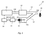
- FIG. 1 illustrates a principle diagram of an active-sound-profiling system, designated by the reference number 10.
- an engine 11 comprises a primary exhaust path 13, along which the sound of the engine 11, i.e., the acoustic waves EW, propagates.
- a system 12 for after-treatment of exhaust gases.
- a microphone 18 for measuring the sound.
- the active-sound-profiling system 10 moreover comprises a secondary exhaust path 17, giving out into which is a diffuser or speaker 16, the secondary path converging in the primary path 13 in a merge point downstream of the exhaust-gas after-treatment system 12 and upstream of the outlet of the primary path 13 and of the microphone 18.
- the active-sound-profiling system 10 moreover comprises an ESPU (Electronic Sound-Profiling Unit) 15.
- the ESPU 15 receives from an ECU (Engine Control Unit) 14 information regarding a workpoint WP of an engine 11, in particular, for example, an internal-combustion engine.
- This information regarding a workpoint WP includes, for example, a number of values of engine r.p.m. ER and/or the signal indicating the gas-pedal percentage GP, i.e., the position of the accelerator pedal expressed as a percentage.
- the electronic sound-profiling unit 15 drives a speaker 16 via a driving signal SP in order to generate second acoustic waves MW injected into the secondary exhaust path 17, which add to the engine acoustic waves EW in the primary path 13, downstream of the after-treatment system 12, in the merge point with the secondary path 17, so that at output from the primary path 13 third resulting acoustic waves RW are formed, which identify an engine sound different from the sound identified by the first waves EW, which correspond to the original sound of the engine 11 and can be measured, for example, using the microphone 18.
- the microphone 18 does not form part of the system in normal running conditions of the vehicle, and has the calibration purposes what will be illustrated in what follows.
- a problem of known systems is to tune with sufficient accuracy the amplitudes of the injected acoustic waves to obtain the desired resulting acoustic waves.
- the object of the present invention is to provide an improved method that will make it possible to tune with greater accuracy as compared to known solutions the amplitudes of the injected acoustic waves to obtain the desired resulting acoustic waves.
- the above object is achieved thanks to an active-sound-profiling method, as well as to a corresponding system having the characteristics specified in the ensuing claims.
- the solution according to the invention regards an active-sound-profiling method and a corresponding system that automatically tunes the amplitudes of the waves injected into the secondary path, using modules configured with a simulation environment and a mathematical model, which describes the physical path from the speaker to the exhaust, measuring the sound with a microphone.
- the solution can be applied not only to vehicles with internal-combustion engines, but also to electric vehicles, applying the method to the specific physical path from the speaker to the microphone, or else to other physical paths.
- the solution described comprises an automatic procedure that tunes the amplitudes of the injected waves, choosing values from a set of software parameters that represent equalization coefficients, which are a function of the workpoint WP and are stored in the sound-profiling unit.
- LUT Look-Up Table
- a workpoint expressed, for example, via the engine r.p.m. and the position of the gas pedal. It is envisaged to provide a look-up table for each frequency injected.
- the required amplitudes can be tuned off-line via a self-tuning procedure.
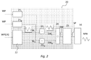
- the method can in general be implemented in a system similar to the system 10 of Figure 1 , where instead of the sound-profiling unit 15 a sound-profiling unit 20 is used configured as illustrated schematically in Figure 2 .
- the above profiling unit 20 receives at input from the ECU 14 the workpoint WP of the engine 11 represented by a pair of values of engine r.p.m. ER and position of gas pedal GP, the latter quantity substantially representing the engine torque. As shown in Figure 2 , the profiling unit 20 preferably has as input only the information regarding a workpoint WP of the engine 11.
- the basic harmonics W 1 , ..., W M will in general have an amplitude equal to unity.
- the profiling unit 20 thus comprises M respective look-up tables 21, respectively 21 1 , ..., 21 M .
- Each i-th look-up table 21 i for a specific corresponding harmonic W 1 , associates to a value of workpoint WR a respective equalization coefficient ⁇ i . Consequently, the look-up tables 21 generate M equalization coefficients ⁇ 1 , ..., ⁇ M .
- the digital driving wave DW is supplied to a digital-to-analog converter 25, which determines the driving signal SP, which is an analog signal, in particular an analog voltage.
- This driving signal 15 is supplied to the diffuser, or speaker 16, which injects the second acoustic waves MW into the secondary path 17.
- Figure 3 shows a flowchart illustrating the operations of the method described herein, designated as a whole by the reference 100.
- Designated by 110 is the step of generation of basic harmonics W 1 , ..., W M , as a function of the frequency f associated to the current workpoint WP of the engine 11.
- Designated by 120 is an operation of generation of the equalization coefficients ⁇ 1 , ..., ⁇ M as a function of the values of workpoint WP, using, as discussed with reference to Figure 2 , M look-up tables 21, respectively 21 1 , ..., 21 M , which, for a corresponding specific harmonic W 1 , associate to a value of workpoint WP a respective equalization coefficient ⁇ i .
- the values of equalization coefficients ⁇ i as a function of the workpoint WR in the look-up tables 21 are obtained via a procedure 200 of calculation of the equalization coefficients that will be described with reference to Figure 4 .
- step 140 all the equalized harmonics EW i are added together to obtain a digital driving wave DW.
- a step 150 the digital driving wave DW is converted into an analog signal, the driving signal SP.
- a step 160 the driving signal SP is supplied to the diffuser 16, which generates the second acoustic waves MW.
- the second acoustic waves MW pass through the secondary path 17 and flow into in the primary path 13, combining with the first waves EW, to yield the third resulting waves RW, which are perceived by the users under normal conditions of use of the vehicle or can be measured by the microphone 18.
- the equalization coefficients ⁇ 1 , ..., ⁇ M stored in the LUTs 21 that reside in the profiling unit 20 are determined via a self-tuning procedure 200 (illustrated in Figure 4 ), which substantially envisages determination of the aforesaid equalization coefficients ⁇ 1 , ..., ⁇ M as a function of reference acoustic waves TW and of a model H of the secondary path 16.
- the reference acoustic waves TW are the reference acoustic waves that it is desired to reproduce at output from the primary path 13, i.e., the waves that the third resulting waves RW are required to reproduce; thus, in particular, they are the waves that represent the sound of another engine of another vehicle.
- the model H of the secondary path 17 describes, instead, how the sound emitted by the diffuser 16 is modified and then detected by the microphone 18 at the end of the primary exhaust path 13.
- the model H represents, that is, a transfer function from an input, represented by the driving signal SP to an output, represented by the resulting waves RW.
- the model H also includes the diffuser 16.
- the diffuser 16 is usually included in an acoustic chamber; in this case, the model also includes this chamber.
- the microphone 18 is not comprised in the active-profiling system implemented on a vehicle, but is used only for calibrating the amplitudes of the acoustic waves of the system and for modelling the secondary path 17.
- the active-sound-profiling system described herein carries out open-loop regulation of the equalization coefficients.
- This open loop for regulation of the equalization coefficients receives at input the information regarding a workpoint WP and supplies at output the third resulting acoustic waves RW, which identify an engine sound different from the sound identified by the first waves EW corresponding to the original sound of the engine 11.
- the self-tuning procedure 200 is implemented in a simulation environment, i.e., for example on a processor in an in-factory setting step, in any case prior to the method 100, via the following steps:
- the steps 210 and 220 are carried out for a plurality of workpoints WP so that, for each workpoint WP, there is a respective set of amplitudes TA 1 , ..., TAM of reference harmonics.
- an optimization procedure 270 is carried out that envisages injection 230 of a simulation SMW of the second acoustic waves MW into the model H to obtain corresponding simulated resulting waves SRW.
- This step 230 is carried out a number of times with different values of equalization coefficients that model the amplitudes of the second injected waves SMW. Since it is an iterative procedure, in a first step initial values of second simulated acoustic waves SMW will be injected, with initial values of coefficients of the second simulated acoustic waves SMW, whereas in the subsequent iterations the current values produced by the optimization procedure 270 in the previous iteration are used.
- step 230 there follows an operation 240 of addition of the simulated resulting waves SRW to the reference waves TW to obtain a sum wave SW, which in a step 250 is transformed via FFT into a transformed sum wave TSW, of which M amplitudes SA 1 , ..., SA M are extrapolated according to the number M of harmonics and the running frequency f of the engine 11.
- a step 260 there is carried out evaluation and minimizazion of a cost function as a function of the M amplitudes TA 1 , ..., TAM of reference harmonics and of the transformed sum wave TSW, in particular as a function of their difference, for example the sum of the errors between the amplitudes TA 1 , ..., TA M of reference harmonics and amplitudes SA 1 , ..., SA M of the transformed sum wave TSW.
- equalization coefficients ⁇ 1 , ..., ⁇ M produced at output, for a given value of workpoint WP, by the optimization procedure 270 are the ones that minimize the cost function.
- steps 230-260 are carried out for a plurality of workpoints WP, so that for each workpoint WP there is a respective set of amplitudes SA 1 , ..., SA M of simulated harmonics.
- the operations of the procedure 200 are carried out a number of times for a plurality of workpoints WP, defined by pairs of values of engine r.p.m. and gas-pedal position, to yield at output sets of equalization coefficients ⁇ 1 , ..., ⁇ M for each of the aforesaid workpoints WP.
- the steps 230-260 are moreover carried out iteratively, varying the amplitude (coefficients) of the second simulated acoustic waves SMW.
- the optimal equalization coefficients ⁇ 1 , ..., ⁇ M obtained in the simulation environment can be refined in a real environment equipped with a sound-profiling system by intervening on the parameters ⁇ 1 , ..., ⁇ M via manual tuning, according, for example, to the impression obtained by a skilled operator from listening to the engine.
- the model H of the secondary path can be obtained using a FIR (Finite Impulse Response) filter.
- FIR Finite Impulse Response
- white noise WN is injected, via the diffuser 16, into the secondary path 17, keeping the engine 11 turned off and recording, with the microphone 18, both the driving signal SP (input signal u to the model H) associated to the white noise SW and the resulting waves RW at output from the primary path 13 (output signal y from the model H).
- the purpose of the model H of the secondary path is to be able to estimate how the sound emitted by the diffuser 16, which is located in an acoustic chamber 16a included in the secondary path 17, is modified by the path comprising the secondary path 17 and the stretch of primary path 13 from the merge point of confluence to the exhaust outlet, where the sound is measured by the microphone 18.
- the procedure of identification of the model H hence comprises performing, with the engine 11 off, the following steps:
- the steps 310-350 are repeated a number of times with different levels of amplitude of white noise WN generated in step 310 in order to obtain a first evaluation and then robustness of identification.
- the active-sound-profiling method described enables tuning with greater accuracy, as compared to known solutions, of the amplitudes of the injected acoustic waves to obtain the desired resulting acoustic waves.
- the profiling method is able to equalize engine sounds characterized both in amplitude and engine orders, or acoustic frequencies, possibly adding new frequencies to the original sound of the engine.
- the solution can be applied not only to vehicles with internal-combustion engines, but also to electrically propelled vehicles, applying the method to the specific physical path from the speaker to the microphone, or to other physical paths.
Abstract
said method comprising:
injecting (160), via an acoustic-wave diffuser (16), into a secondary propagation path (17) that merges in said primary path (13), second acoustic waves (MW), which are able to combine with said first acoustic waves (EW) in a merge point in said primary propagation path (13) and to generate (170) third resulting acoustic waves (RW); and
generating (110, 120, 130, 140, 150) a driving signal (SP) for said diffuser (16) by regulating (110, 120, 130) the amplitude of harmonics of said driving signal (SP) as a function of reference acoustic waves (TW) and of a workpoint (WP) of the engine (11). This regulation operation (110, 120, 130) comprises calculating (110) equalization coefficients (α1, ..., αM) to be applied to the amplitudes of said harmonics of said driving signal (SP) via a self-tuning procedure (200), which comprises comparing (260) said reference acoustic waves (TW) with a simulation (SRW) of said resulting waves (RW), said simulation (SRW) being obtained by applying (230) to a simulation (MSW) of the second acoustic waves (MW) a model (H) of the secondary propagation path (17).
Description
- The present invention relates to techniques for performing an active profiling of the sound emitted by a vehicle engine that issues first acoustic waves along a primary path of propagation of acoustic waves, in particular an exhaust duct, the method comprising:
- injecting, via an acoustic-wave diffuser, into a secondary propagation path that merges in said primary path, second acoustic waves that are able to combine with said first acoustic waves in a merge point in said primary propagation path and to generate third resulting acoustic waves; and
- generating a signal for driving the aforesaid diffuser by regulating the amplitude of harmonics of the driving signal as a function of reference acoustic waves and of a workpoint of the engine.
- The above techniques are described herein with specific reference to internal-combustion engines; however, they may refer to other types of engines, for example electric engines.
- It is known in the automotive sector to use systems for so-called active sound profiling, which aim at reproducing a given sound profile. Active-sound-profiling techniques can be adopted, for example, for improving the quality of sound inside the passenger compartment of motor vehicles for transport of passengers by modifying the noise of the engine within the passenger compartment. This modification may envisage that the noise of the engine is modified so as to be similar to that of the engine of another model of motor vehicle, for example a prestige-level automobile.
- An active-sound-profiling system normally envisages use of an electronic control unit, which, on the basis of internal information that it receives at input regarding the workpoint of the internal-combustion engine, actuates a diffuser in the exhaust system, in particular downstream of the gas after-treatment system. This system has the purpose of injecting, in addition to the sound actually emitted by the engine itself, a precise set of acoustic waves (harmonics) with frequencies corresponding to the current engine workpoint (pedal/r.p.m. and load/fuel). The amplitudes of the injected waves are tuned to follow the amplitudes associated to another motor vehicle that is defined as "target vehicle" at each engine workpoint. In this way, the original sound of the motor vehicle is coloured and becomes similar to the sound of the target vehicle. The waves to inject, i.e., the frequencies to inject, and their amplitudes are selected on the basis of the waves that identify the target sound (i.e., in the target-sound spectrum) of the target vehicle so as to imitate its tone.
-
Figure 1 illustrates a principle diagram of an active-sound-profiling system, designated by thereference number 10. In general, anengine 11 comprises aprimary exhaust path 13, along which the sound of theengine 11, i.e., the acoustic waves EW, propagates. Inserted along theprimary path 13 is asystem 12 for after-treatment of exhaust gases. Appearing at the outlet of theprimary path 13 is amicrophone 18 for measuring the sound. The active-sound-profiling system 10 moreover comprises asecondary exhaust path 17, giving out into which is a diffuser orspeaker 16, the secondary path converging in theprimary path 13 in a merge point downstream of the exhaust-gas after-treatment system 12 and upstream of the outlet of theprimary path 13 and of themicrophone 18. The active-sound-profiling system 10 moreover comprises an ESPU (Electronic Sound-Profiling Unit) 15. The ESPU 15 receives from an ECU (Engine Control Unit) 14 information regarding a workpoint WP of anengine 11, in particular, for example, an internal-combustion engine. This information regarding a workpoint WP includes, for example, a number of values of engine r.p.m. ER and/or the signal indicating the gas-pedal percentage GP, i.e., the position of the accelerator pedal expressed as a percentage. The electronic sound-profiling unit 15 drives aspeaker 16 via a driving signal SP in order to generate second acoustic waves MW injected into thesecondary exhaust path 17, which add to the engine acoustic waves EW in theprimary path 13, downstream of the after-treatment system 12, in the merge point with thesecondary path 17, so that at output from theprimary path 13 third resulting acoustic waves RW are formed, which identify an engine sound different from the sound identified by the first waves EW, which correspond to the original sound of theengine 11 and can be measured, for example, using themicrophone 18. Clearly, themicrophone 18 does not form part of the system in normal running conditions of the vehicle, and has the calibration purposes what will be illustrated in what follows. - A problem of known systems is to tune with sufficient accuracy the amplitudes of the injected acoustic waves to obtain the desired resulting acoustic waves.
- The object of the present invention is to provide an improved method that will make it possible to tune with greater accuracy as compared to known solutions the amplitudes of the injected acoustic waves to obtain the desired resulting acoustic waves.
- According to the present invention, the above object is achieved thanks to an active-sound-profiling method, as well as to a corresponding system having the characteristics specified in the ensuing claims.
- The invention will now be described with reference to the annexed drawings, which are provided purely by way of non-limiting example and in which:
-
Figure 1 is a schematic view of a system according to the prior art; -
Figure 2 is a detailed diagram of a module of a system implementing the method according to the invention; -
Figure 3 is a flowchart of the profiling method according to the invention; -
Figure 4 is a flowchart of a self-tuning procedure used in association with the method ofFigure 3 ; and -
Figure 5 is a flowchart of a procedure for obtaining a model of a path of acoustic waves, which is used by the method ofFigure 3 . - In brief, the solution according to the invention regards an active-sound-profiling method and a corresponding system that automatically tunes the amplitudes of the waves injected into the secondary path, using modules configured with a simulation environment and a mathematical model, which describes the physical path from the speaker to the exhaust, measuring the sound with a microphone.
- In various embodiments, the solution can be applied not only to vehicles with internal-combustion engines, but also to electric vehicles, applying the method to the specific physical path from the speaker to the microphone, or else to other physical paths.
- In various embodiments, the solution described comprises an automatic procedure that tunes the amplitudes of the injected waves, choosing values from a set of software parameters that represent equalization coefficients, which are a function of the workpoint WP and are stored in the sound-profiling unit.
- In particular, it is envisaged to map the values of amplitude of the injected waves in a LUT (Look-Up Table), which receives at input a workpoint expressed, for example, via the engine r.p.m. and the position of the gas pedal. It is envisaged to provide a look-up table for each frequency injected.
- The required amplitudes can be tuned off-line via a self-tuning procedure.
- The method can in general be implemented in a system similar to the
system 10 ofFigure 1 , where instead of the sound-profiling unit 15 a sound-profiling unit 20 is used configured as illustrated schematically inFigure 2 . - The
above profiling unit 20 receives at input from theECU 14 the workpoint WP of theengine 11 represented by a pair of values of engine r.p.m. ER and position of gas pedal GP, the latter quantity substantially representing the engine torque. As shown inFigure 2 , theprofiling unit 20 preferably has as input only the information regarding a workpoint WP of theengine 11. - Given a number M of harmonics that have been selected to be used for generating the driving signal SP, the
profiling unit 20 comprises a harmonic-generation module 22, which generates, as a function of the engine r.p.m. ER, or rather of a frequency of rotation f (1 Hz = 60 r.p.m.) corresponding to the value of the engine r.p.m. ER, measured by theunit 14 in the time domain, M basic harmonics W1, ..., WM of respective order ranging from 1 through M. The first harmonic W1 is a sinusoid with frequency f1 = f, i.e., equal to the frequency corresponding that of the engine workpoint, and the M-th harmonic has a frequency fM = M · f. The basic harmonics W1, ..., WM will in general have an amplitude equal to unity. - The
profiling unit 20 thus comprises M respective look-up tables 21, respectively 211, ..., 21M. Each i-th look-up table 21i, for a specific corresponding harmonic W1, associates to a value of workpoint WR a respective equalization coefficient αi. Consequently, the look-up tables 21 generate M equalization coefficients α1, ..., αM. A block of M multipliers 23 then multiplies each equalization coefficient α1, ..., αM by the amplitude of the harmonic W1, ..., WM of corresponding order, generating equalized harmonics EW1, ..., EWM, where EWi = αi · Wi. - Then, in an adder 24, all the equalized harmonics EWi are added together to obtain a digital driving wave DW, such that:

- The digital driving wave DW is supplied to a digital-to-analog converter 25, which determines the driving signal SP, which is an analog signal, in particular an analog voltage. This
driving signal 15 is supplied to the diffuser, orspeaker 16, which injects the second acoustic waves MW into thesecondary path 17. -
Figure 3 shows a flowchart illustrating the operations of the method described herein, designated as a whole by thereference 100. - Designated by 110 is the step of generation of basic harmonics W1, ..., WM, as a function of the frequency f associated to the current workpoint WP of the
engine 11. - Designated by 120 is an operation of generation of the equalization coefficients α1, ..., αM as a function of the values of workpoint WP, using, as discussed with reference to
Figure 2 , M look-up tables 21, respectively 211, ..., 21M, which, for a corresponding specific harmonic W1, associate to a value of workpoint WP a respective equalization coefficient αi. The values of equalization coefficients αi as a function of the workpoint WR in the look-up tables 21 are obtained via aprocedure 200 of calculation of the equalization coefficients that will be described with reference toFigure 4 . - Next, in a
step 130, each equalization coefficient α1, ..., αM generated by arespective LUT 211, ..., 21M, for a given workpoint WR, is multiplied by the amplitude of the harmonic W1, ..., WM of corresponding order, to generate equalized harmonics EW1, ..., EWM, where EWi = αi · Wi. - Then, in a
step 140 all the equalized harmonics EWi are added together to obtain a digital driving wave DW. - In a
step 150, the digital driving wave DW is converted into an analog signal, the driving signal SP. - In a
step 160, the driving signal SP is supplied to thediffuser 16, which generates the second acoustic waves MW. - In a
step 170, the second acoustic waves MW pass through thesecondary path 17 and flow into in theprimary path 13, combining with the first waves EW, to yield the third resulting waves RW, which are perceived by the users under normal conditions of use of the vehicle or can be measured by themicrophone 18. - As may be seen from the diagram of
Figure 3 , the equalization coefficients α1, ..., αM stored in theLUTs 21 that reside in theprofiling unit 20 are determined via a self-tuning procedure 200 (illustrated inFigure 4 ), which substantially envisages determination of the aforesaid equalization coefficients α1, ..., αM as a function of reference acoustic waves TW and of a model H of thesecondary path 16. - The reference acoustic waves TW are the reference acoustic waves that it is desired to reproduce at output from the
primary path 13, i.e., the waves that the third resulting waves RW are required to reproduce; thus, in particular, they are the waves that represent the sound of another engine of another vehicle. - The model H of the
secondary path 17 describes, instead, how the sound emitted by thediffuser 16 is modified and then detected by themicrophone 18 at the end of theprimary exhaust path 13. The model H represents, that is, a transfer function from an input, represented by the driving signal SP to an output, represented by the resulting waves RW. In general, then, the model H also includes thediffuser 16. Thediffuser 16 is usually included in an acoustic chamber; in this case, the model also includes this chamber. As has been said, themicrophone 18 is not comprised in the active-profiling system implemented on a vehicle, but is used only for calibrating the amplitudes of the acoustic waves of the system and for modelling thesecondary path 17. Consequently, the active-sound-profiling system described herein carries out open-loop regulation of the equalization coefficients. In fact, during operation, there is no feedback signal from the output, in particular from themicrophone 18. This open loop for regulation of the equalization coefficients receives at input the information regarding a workpoint WP and supplies at output the third resulting acoustic waves RW, which identify an engine sound different from the sound identified by the first waves EW corresponding to the original sound of theengine 11. - Assuming that amplitudes of the acoustic waves are to be calibrated as a function of a specific pair of values of r.p.m. ER of the
engine 11 and of position of the gas pedal GP, which represents a specific workpoint WP of theengine 11, the self-tuningprocedure 200 is implemented in a simulation environment, i.e., for example on a processor in an in-factory setting step, in any case prior to themethod 100, via the following steps: - applying 210 an FFT (Fast Fourier Transform) to the reference acoustic waves TW of a reference vehicle, in particular to a recording of said waves TW made previously, to obtain a reference spectrum TTW; and
- extrapolating 220, or extracting, from said reference spectrum TTW M amplitudes TA1, ..., TAM of reference harmonics that the method and system described herein must imitate in the third resulting waves RW.
- The
steps - Moreover, for each workpoint WP an
optimization procedure 270 is carried out that envisagesinjection 230 of a simulation SMW of the second acoustic waves MW into the model H to obtain corresponding simulated resulting waves SRW. Thisstep 230 is carried out a number of times with different values of equalization coefficients that model the amplitudes of the second injected waves SMW. Since it is an iterative procedure, in a first step initial values of second simulated acoustic waves SMW will be injected, with initial values of coefficients of the second simulated acoustic waves SMW, whereas in the subsequent iterations the current values produced by theoptimization procedure 270 in the previous iteration are used. - At each execution of
step 230, there follows anoperation 240 of addition of the simulated resulting waves SRW to the reference waves TW to obtain a sum wave SW, which in astep 250 is transformed via FFT into a transformed sum wave TSW, of which M amplitudes SA1, ..., SAM are extrapolated according to the number M of harmonics and the running frequency f of theengine 11. - Then, in a
step 260, there is carried out evaluation and minimizazion of a cost function as a function of the M amplitudes TA1, ..., TAM of reference harmonics and of the transformed sum wave TSW, in particular as a function of their difference, for example the sum of the errors between the amplitudes TA1, ..., TAM of reference harmonics and amplitudes SA1, ..., SAM of the transformed sum wave TSW. - The values of equalization coefficients α1, ..., αM produced at output, for a given value of workpoint WP, by the
optimization procedure 270, are the ones that minimize the cost function. - Also the steps 230-260 are carried out for a plurality of workpoints WP, so that for each workpoint WP there is a respective set of amplitudes SA1, ..., SAM of simulated harmonics.
- In other words, the operations of the
procedure 200 are carried out a number of times for a plurality of workpoints WP, defined by pairs of values of engine r.p.m. and gas-pedal position, to yield at output sets of equalization coefficients α1, ..., αM for each of the aforesaid workpoints WP. During execution of theprocedure 200 for a given workpoint WP, the steps 230-260 are moreover carried out iteratively, varying the amplitude (coefficients) of the second simulated acoustic waves SMW. - The optimal equalization coefficients α1, ..., αM obtained in the simulation environment can be refined in a real environment equipped with a sound-profiling system by intervening on the parameters α1, ..., αM via manual tuning, according, for example, to the impression obtained by a skilled operator from listening to the engine.
- The model H of the secondary path can be obtained using a FIR (Finite Impulse Response) filter. In order to calibrate the parameters of the FIR filter that implements the model H, white noise WN is injected, via the
diffuser 16, into thesecondary path 17, keeping theengine 11 turned off and recording, with themicrophone 18, both the driving signal SP (input signal u to the model H) associated to the white noise SW and the resulting waves RW at output from the primary path 13 (output signal y from the model H). If a number of measurements are made, by sending different input signals u a number of times and measuring the corresponding output signals y, it is then possible to calculate values of the parameters, in particular the coefficients bi, of the FIR filter of the model H of the secondary path, applying in a processor a procedure of regression, in particular the LMS (Least Mean Square) regression, following procedures of calibration of adaptive filters that employ the LMS procedure that are in themselves known. - The purpose of the model H of the secondary path is to be able to estimate how the sound emitted by the
diffuser 16, which is located in anacoustic chamber 16a included in thesecondary path 17, is modified by the path comprising thesecondary path 17 and the stretch ofprimary path 13 from the merge point of confluence to the exhaust outlet, where the sound is measured by themicrophone 18. - The procedure of identification of the model H, designated by 300 in
Figure 5 , hence comprises performing, with theengine 11 off, the following steps: - in a
step 310, a digital white-noise signal WN is generated, by theprofiling unit 20, for example via a random-number generator module; - this white-noise signal generated in
step 310 is sent at input to the converter 25, which produces a driving signal SP associated to white noise, i.e., a signal SP(WN); in this step, it is also possible to filter the white noise WN via a band-pass filter for cutting off the low frequencies that determine nonlinearities of the system (distortion in frequency of the sound) and the high frequencies that are not used by the profiling system; - in
step 330, the driving signal associated to the white noise SP(WN) generates, via thediffuser 16, injected waves MW(WN) as a function of the white noise; - in step 340, after propagation of the acoustic waves along the
secondary path 17 and confluence thereof in theprimary path 13, a measurement is made of the resulting waves RW, corresponding to the output of the model y, which are voltage or pressure values measured by themicrophone 18; it may be noted, in particular, that it is envisaged to acquire in a synchronous way the output of the converter module 25, i.e., the voltage that represents the input u, and the voltage (or pressure) of themicrophone 18, i.e., the output signal y: it may be noted that it is preferable to start acquisition with a brief period of silence (3-4 s) and then to inject white noise WN and the corresponding driving signal SP(WN); this enables estimation of the travel delay from the converter 25 to themicrophone 18; - in
step 350, off-line, in a processor, an LSM procedure is carried out, on the basis of an input signal u corresponding to the driving signal SP (WN) and on the basis of an output signal y corresponding to the resulting waves RW; thesecondary path 17 is modelled according to the equation of the FIR filter y[n] corresponding to the model H in the time domain:
- The steps 310-350 are repeated a number of times with different levels of amplitude of white noise WN generated in
step 310 in order to obtain a first evaluation and then robustness of identification. - Hence, from what has been described above, the advantages of the solution proposed emerge clearly.
- The active-sound-profiling method described enables tuning with greater accuracy, as compared to known solutions, of the amplitudes of the injected acoustic waves to obtain the desired resulting acoustic waves. The profiling method is able to equalize engine sounds characterized both in amplitude and engine orders, or acoustic frequencies, possibly adding new frequencies to the original sound of the engine.
- In various embodiments, the solution can be applied not only to vehicles with internal-combustion engines, but also to electrically propelled vehicles, applying the method to the specific physical path from the speaker to the microphone, or to other physical paths.
Claims (12)
- A method for performing an active profiling of the sound emitted by a vehicle engine (11) that issues first acoustic waves (EW) along a primary path (13) of propagation of acoustic waves, in particular an exhaust duct,
said method comprising:injecting (160), via an acoustic-wave diffuser (16), into a secondary propagation path (17) that merges in said primary path (13), second acoustic waves (MW), which are able to combine with said first acoustic waves (EW) in a merge point in said primary propagation path (13) and to generate (170) third resulting acoustic waves (RW); andgenerating (110, 120, 130, 140, 150) a driving signal (SP) for driving said diffuser (16) by regulating (110, 120, 130) the amplitude of harmonics of said driving signal (SP) as a function of reference acoustic waves (TW) and of a workpoint (WP) of the engine (11),characterized in that said operation of regulation (110, 120, 130) comprises:calculating (110) equalization coefficients (α1, ..., αM) to be applied to the amplitudes of said harmonics of said driving signal (SP) via a self-tuning procedure (200), which comprises comparing (260) said reference acoustic waves (TW) with a simulation (SRW) of said resulting waves (RW), said simulation (SRW) being obtained by applying (230), to a simulation (MSW) of the second injected acoustic waves (MW), a model (H) of the secondary propagation path (17). - The method according to Claim 1, characterized in that it comprises:generating (110) basic harmonics (W1, ..., WM) as a function of the current workpoint (WP) of the engine (11) ;obtaining (120) said equalization coefficients (α1, ..., αM) as a function of the values of workpoint (WP) using respective look-up tables (21) for each harmonic (Wi), which supply, as a function of the value of current workpoint (WP) of the engine (11), a respective equalization coefficient (αi).
- The method according to Claim 2, characterized in that it comprises obtaining (130) equalized harmonics (EW1, ..., EWM) as a function of said equalization coefficients (α1, ..., αM) ;
adding (140) together said equalized harmonics (EW1, ..., EWM) to obtain a digital driving wave (DW); and
converting (150) said digital driving wave (DW) into an analog signal corresponding to the driving signal (SP). - The method according to Claim 2 or Claim 3, characterized in that said operation (110) of generating basic harmonics (W1, ..., WM) comprises generating, as a function of the engine r.p.m. (ER), a pre-set number (M) of basic harmonics (W1, ..., WM) of a sinusoidal signal at the frequency (f) identified by said engine r.p.m. (ER)
- The method according to any one of the preceding claims, characterized in that said self-tuning procedure (200) comprises:applying (210) an FFT (Fast Fourier Transform) to the reference acoustic waves (TW), which in particular are originated by a reference vehicle, to obtain a reference spectrum (TTW), and extrapolating (220) from said reference spectrum (TTW) amplitudes (TA1, ..., TAM) of reference harmonics;injecting (230) a simulation (MSW) of the second acoustic waves (MW) into the model (H) of the secondary path and obtaining corresponding simulated resulting waves (SRW), in particular for different values of equalization coefficients (α1, ..., αM) that model the amplitudes of the second injected waves (MW);adding (240) the resulting waves (RW) to the reference waves (TW) and applying (250) a transform (FFT) to a resulting sum wave (SW), to obtain a transformed sum wave (TSW);evaluating and minimizing a cost function (CF) as a function of the amplitudes (TA1, ..., TAM) of reference harmonics and of amplitudes (SA1, ..., SAM) of the transformed sum wave (TSW), in particular as a function of their difference calculated as sum of the errors between the amplitudes (TA1, ..., TAM) of reference harmonics and amplitudes (SA1, ..., SAM) of the transformed sum wave (TSW), supplying as values of equalization coefficients (α1, ..., αM) for a given value of workpoint (WP) the values that minimize said cost function (CF).
- The method according to any one of the preceding claims, characterized in that it comprises an identification procedure (300) for identifying said model (H) of the secondary path, said procedure comprises calculating the parameters of a FIR (Finite Impulse Response) filter.
- The method according to any one of the preceding claims, characterized in that said calculation (300) of the parameters of a FIR filter comprises:generation and injection (310), via the diffuser (16), white noise (WN) into the secondary path (17), keeping the engine (11) turned off, both acquiring (320) the driving signal (SP) associated to the white noise (WN) as input signal (u) of the model (H) and acquiring (340) the corresponding resulting waves (RW) at output from the primary path (13) as output signal (y) of the model (H), repeating said operation of injection a plurality of times with different amplitudes of white noise (WN) at input, to obtain different instances of output signal (y); andcalculation (350) of values of parameters (bi) of the FIR filter of the model (H) of the secondary path, applying a regression as a function of said plurality of instances of inputs (u) and outputs (y), in particular applying an LMS (Least Mean Square) procedure.
- The method according to any one of the preceding claims, characterized in that said workpoint (WP) comprises a value of engine r.p.m. (ER) and a value of gas-pedal percentage (GP), which are, in particular, issued by an electronic control unit (14) of the vehicle.
- A system for active profiling of the sound emitted by a vehicle engine (11) that issues first acoustic waves (EW) along a primary path (13) of propagation of acoustic waves, in particular an exhaust duct, said system comprising a secondary path (17), which merges in said primary path (13), in which an acoustic-wave diffuser (16) injects (160) second acoustic waves (MW), which are able to combine with said first acoustic waves (EW) in a merge point in said primary propagation path (13) and to generate (170) third resulting acoustic waves (RW), an active-sound-profiling unit (15; 20) configured for generating (110, 120, 130, 140, 150) a driving signal (SP) for said diffuser (16) by regulating (110, 120, 130) the amplitude of harmonics of said driving signal (SP) as a function of reference acoustic waves (TW) and of a workpoint (WP) of the engine (11), said system being characterized in that said active-sound-profiling unit (20) is configured for carrying out said operation of regulation (110, 120, 130) on the basis the method according to any one of Claims 1 to 8.
- The system according to Claim 9, characterized in that said active-profiling unit (20) comprises a harmonic-generation module (22), configured for generating, as a function of the engine r.p.m. (ER), a pre-set number (M) of basic harmonics (W1, ..., WM) of a sinusoidal signal at a frequency (f) identified by said engine r.p.m. (ER), and a plurality of look-up tables (21), each look-up table (21i), for a specific corresponding harmonic (Wi), associating to a value of workpoint (WR) a respective equalization coefficient (αi).
- The system according to Claim 9 or Claim 10, characterized in that said engine (11) is an internal-combustion engine or an electric engine.
- The system according to any one of Claims 9 to 11, characterized in that it is configured for carrying out said self-tuning procedure (200) and/or said identification procedure (300) for identifying the model (H) of the secondary path (17) on one or more processors that implement simulation environments.
Applications Claiming Priority (1)
| Application Number | Priority Date | Filing Date | Title |
|---|---|---|---|
| ITTO20141104 | 2014-12-24 |
Publications (2)
| Publication Number | Publication Date |
|---|---|
| EP3038102A1 true EP3038102A1 (en) | 2016-06-29 |
| EP3038102B1 EP3038102B1 (en) | 2019-07-24 |
Family
ID=52682840
Family Applications (1)
| Application Number | Title | Priority Date | Filing Date |
|---|---|---|---|
| EP15201755.4A Not-in-force EP3038102B1 (en) | 2014-12-24 | 2015-12-21 | Method for performing an active profiling of a sound emitted by an engine and corresponding profiling system |
Country Status (2)
| Country | Link |
|---|---|
| US (1) | US10356539B2 (en) |
| EP (1) | EP3038102B1 (en) |
Families Citing this family (1)
| Publication number | Priority date | Publication date | Assignee | Title |
|---|---|---|---|---|
| US10074358B1 (en) * | 2017-09-07 | 2018-09-11 | GM Global Technology Operations LLC | Audio control systems and methods for vehicles with variable compression ratio engines |
Citations (7)
| Publication number | Priority date | Publication date | Assignee | Title |
|---|---|---|---|---|
| EP0481450A1 (en) * | 1990-10-19 | 1992-04-22 | HEINRICH GILLET GmbH & CO. KG | Silencer arrangement for internal combustion engines |
| EP0526111A2 (en) * | 1991-07-31 | 1993-02-03 | Fujitsu Ten Limited | Automatic sound controlling apparatus |
| WO1995009415A1 (en) * | 1993-09-28 | 1995-04-06 | Noise Cancellation Technologies, Inc. | Active control system for noise shaping |
| DE102006059351A1 (en) * | 2006-12-15 | 2008-06-19 | Robert Bosch Gmbh | Method for influencing sound |
| EP1947642A1 (en) * | 2007-01-16 | 2008-07-23 | Harman/Becker Automotive Systems GmbH | Active noise control system |
| EP2600342A2 (en) * | 2011-12-02 | 2013-06-05 | J. Eberspächer GmbH & Co. KG | Active design of exhaust sounds |
| WO2013114807A1 (en) * | 2012-02-03 | 2013-08-08 | 三菱電機株式会社 | Active noise control device |
Family Cites Families (14)
| Publication number | Priority date | Publication date | Assignee | Title |
|---|---|---|---|---|
| US5692052A (en) * | 1991-06-17 | 1997-11-25 | Nippondenso Co., Ltd. | Engine noise control apparatus |
| JPH07182587A (en) * | 1993-12-21 | 1995-07-21 | Honda Motor Co Ltd | Device for generating pseudo sound for electric vehicle |
| JPH08158966A (en) * | 1994-11-30 | 1996-06-18 | Nippondenso Co Ltd | Noise control device of internal combustion engine |
| KR19990044170A (en) * | 1995-09-02 | 1999-06-25 | 헨리 에이지마 | Panel Loudspeakers |
| DE19949685A1 (en) * | 1999-10-15 | 2001-04-19 | Mann & Hummel Filter | Active control of noise generated at air intake of internal combustion engine uses noise cancellation |
| JP2005219715A (en) * | 2004-02-09 | 2005-08-18 | Pioneer Electronic Corp | Pseudo sound generating device, vehicle, pseudo sound generating method and pseudo sound generating program |
| DE102006061564A1 (en) * | 2006-12-27 | 2008-07-03 | Robert Bosch Gmbh | Sound influencing method for use in vehicle, involves generating sound-influencing signal based on detected sound emission of sound damper in exhaust gas system, and generating sound influencing signal depending on operating mode of engine |
| JP4378391B2 (en) * | 2007-03-28 | 2009-12-02 | 本田技研工業株式会社 | Active noise control system for vehicles |
| EP2110523A1 (en) * | 2008-04-16 | 2009-10-21 | Robert Bosch GmbH | A device and method for active noise cancellation in an exhaust gas channel of a combustion engine |
| US7979147B1 (en) * | 2008-10-06 | 2011-07-12 | James Francis Dunn | Engine sound replication device |
| JP2010155507A (en) * | 2008-12-26 | 2010-07-15 | Yamaha Corp | Engine rotational speed calculation device and engine sound production device |
| WO2011092833A1 (en) * | 2010-01-29 | 2011-08-04 | パイオニア株式会社 | Device and method for pseudonoise generation |
| DE102011018459A1 (en) * | 2011-04-21 | 2012-10-25 | J. Eberspächer GmbH & Co. KG | Übertragungsstreckenkompensator |
| KR20150142298A (en) * | 2014-06-11 | 2015-12-22 | 현대자동차주식회사 | Vehicle, control method of vehicle and vehicle driving sound control apparatus |
-
2015
- 2015-12-21 US US14/977,126 patent/US10356539B2/en active Active
- 2015-12-21 EP EP15201755.4A patent/EP3038102B1/en not_active Not-in-force
Patent Citations (7)
| Publication number | Priority date | Publication date | Assignee | Title |
|---|---|---|---|---|
| EP0481450A1 (en) * | 1990-10-19 | 1992-04-22 | HEINRICH GILLET GmbH & CO. KG | Silencer arrangement for internal combustion engines |
| EP0526111A2 (en) * | 1991-07-31 | 1993-02-03 | Fujitsu Ten Limited | Automatic sound controlling apparatus |
| WO1995009415A1 (en) * | 1993-09-28 | 1995-04-06 | Noise Cancellation Technologies, Inc. | Active control system for noise shaping |
| DE102006059351A1 (en) * | 2006-12-15 | 2008-06-19 | Robert Bosch Gmbh | Method for influencing sound |
| EP1947642A1 (en) * | 2007-01-16 | 2008-07-23 | Harman/Becker Automotive Systems GmbH | Active noise control system |
| EP2600342A2 (en) * | 2011-12-02 | 2013-06-05 | J. Eberspächer GmbH & Co. KG | Active design of exhaust sounds |
| WO2013114807A1 (en) * | 2012-02-03 | 2013-08-08 | 三菱電機株式会社 | Active noise control device |
Non-Patent Citations (1)
| Title |
|---|
| "ADJUSTING THE TONAL QUALITY OF ENGINE NOISE USING ACTIVE NOISE CONTROL TECHNIQUES", RESEARCH DISCLOSURE, MASON PUBLICATIONS, HAMPSHIRE, GB, no. 320, December 1990 (1990-12-01), pages 972 - 973, XP000163374, ISSN: 0374-4353 * |
Also Published As
| Publication number | Publication date |
|---|---|
| US20160192095A1 (en) | 2016-06-30 |
| US10356539B2 (en) | 2019-07-16 |
| EP3038102B1 (en) | 2019-07-24 |
Similar Documents
| Publication | Publication Date | Title |
|---|---|---|
| EP2884489B1 (en) | Sound system including an engine sound synthesizer | |
| US7536018B2 (en) | Active noise cancellation system | |
| US8014538B2 (en) | Active noise reducing device | |
| US20040247137A1 (en) | Apparatus for and method of actively controlling vibratory noise, and vehicle with active vibratory noise control apparatus | |
| CN102568468B (en) | Standing wave attenuation device | |
| CN102750943B (en) | Transmission path compensator | |
| RU2730414C2 (en) | Systems and methods for setting electronic sound improvement | |
| JP6552462B2 (en) | How to model musical instrument characteristics | |
| EP3121808B1 (en) | System for modeling characteristics of an electronic musical instrument | |
| Novak et al. | Nonparametric identification of nonlinear systems in series | |
| EP3038102B1 (en) | Method for performing an active profiling of a sound emitted by an engine and corresponding profiling system | |
| JP5014111B2 (en) | Mode decomposition filter generation apparatus and mode decomposition filter generation method | |
| Cao et al. | Engine order sound simulation by active sound generation for electric vehicles | |
| GB2383224A (en) | Digital filter modelling for active noise cancellation | |
| Janssens et al. | Time-domain source contribution analysis method for in-room pass-by noise | |
| CN113593515A (en) | Wide-band and narrow-band hybrid active noise control system for coping with frequency offset | |
| Wesselink et al. | Fast affine projections and the regularized modified filtered-error algorithm in multichannel active noise control | |
| JP6304643B2 (en) | Nonlinear distortion reduction apparatus, method, and program for speaker | |
| JP6795613B2 (en) | Systems and methods for actively influencing sound | |
| JP5265412B2 (en) | Sound field control device | |
| Pruetz et al. | Active Sound Design Methodologies for Hybrid and Electric Vehicles | |
| JP2743634B2 (en) | Active noise control device | |
| JP4004704B2 (en) | Delay time setting method | |
| Wickman | Active Engine Noise Cancellation Using Vibro-Acoustic Modeling | |
| JP6011076B2 (en) | Fatigue testing machine and driving waveform correction method |
Legal Events
| Date | Code | Title | Description |
|---|---|---|---|
| PUAI | Public reference made under article 153(3) epc to a published international application that has entered the european phase |
Free format text: ORIGINAL CODE: 0009012 |
|
| AK | Designated contracting states |
Kind code of ref document: A1 Designated state(s): AL AT BE BG CH CY CZ DE DK EE ES FI FR GB GR HR HU IE IS IT LI LT LU LV MC MK MT NL NO PL PT RO RS SE SI SK SM TR |
|
| AX | Request for extension of the european patent |
Extension state: BA ME |
|
| STAA | Information on the status of an ep patent application or granted ep patent |
Free format text: STATUS: REQUEST FOR EXAMINATION WAS MADE |
|
| 17P | Request for examination filed |
Effective date: 20161228 |
|
| RBV | Designated contracting states (corrected) |
Designated state(s): AL AT BE BG CH CY CZ DE DK EE ES FI FR GB GR HR HU IE IS IT LI LT LU LV MC MK MT NL NO PL PT RO RS SE SI SK SM TR |
|
| STAA | Information on the status of an ep patent application or granted ep patent |
Free format text: STATUS: EXAMINATION IS IN PROGRESS |
|
| 17Q | First examination report despatched |
Effective date: 20180619 |
|
| GRAP | Despatch of communication of intention to grant a patent |
Free format text: ORIGINAL CODE: EPIDOSNIGR1 |
|
| STAA | Information on the status of an ep patent application or granted ep patent |
Free format text: STATUS: GRANT OF PATENT IS INTENDED |
|
| RIC1 | Information provided on ipc code assigned before grant |
Ipc: F01N 13/00 20100101ALN20190116BHEP Ipc: G10K 15/02 20060101AFI20190116BHEP |
|
| INTG | Intention to grant announced |
Effective date: 20190212 |
|
| GRAS | Grant fee paid |
Free format text: ORIGINAL CODE: EPIDOSNIGR3 |
|
| GRAJ | Information related to disapproval of communication of intention to grant by the applicant or resumption of examination proceedings by the epo deleted |
Free format text: ORIGINAL CODE: EPIDOSDIGR1 |
|
| GRAL | Information related to payment of fee for publishing/printing deleted |
Free format text: ORIGINAL CODE: EPIDOSDIGR3 |
|
| STAA | Information on the status of an ep patent application or granted ep patent |
Free format text: STATUS: EXAMINATION IS IN PROGRESS |
|
| GRAP | Despatch of communication of intention to grant a patent |
Free format text: ORIGINAL CODE: EPIDOSNIGR1 |
|
| STAA | Information on the status of an ep patent application or granted ep patent |
Free format text: STATUS: GRANT OF PATENT IS INTENDED |
|
| GRAA | (expected) grant |
Free format text: ORIGINAL CODE: 0009210 |
|
| STAA | Information on the status of an ep patent application or granted ep patent |
Free format text: STATUS: THE PATENT HAS BEEN GRANTED |
|
| INTG | Intention to grant announced |
Effective date: 20190606 |
|
| RIC1 | Information provided on ipc code assigned before grant |
Ipc: F01N 13/00 20100101ALN20190527BHEP Ipc: G10K 15/02 20060101AFI20190527BHEP |
|
| AK | Designated contracting states |
Kind code of ref document: B1 Designated state(s): AL AT BE BG CH CY CZ DE DK EE ES FI FR GB GR HR HU IE IS IT LI LT LU LV MC MK MT NL NO PL PT RO RS SE SI SK SM TR |
|
| REG | Reference to a national code |
Ref country code: GB Ref legal event code: FG4D |
|
| REG | Reference to a national code |
Ref country code: CH Ref legal event code: EP |
|
| REG | Reference to a national code |
Ref country code: DE Ref legal event code: R096 Ref document number: 602015034211 Country of ref document: DE |
|
| REG | Reference to a national code |
Ref country code: AT Ref legal event code: REF Ref document number: 1159154 Country of ref document: AT Kind code of ref document: T Effective date: 20190815 |
|
| REG | Reference to a national code |
Ref country code: IE Ref legal event code: FG4D |
|
| REG | Reference to a national code |
Ref country code: NL Ref legal event code: MP Effective date: 20190724 |
|
| REG | Reference to a national code |
Ref country code: LT Ref legal event code: MG4D |
|
| REG | Reference to a national code |
Ref country code: AT Ref legal event code: MK05 Ref document number: 1159154 Country of ref document: AT Kind code of ref document: T Effective date: 20190724 |
|
| PG25 | Lapsed in a contracting state [announced via postgrant information from national office to epo] |
Ref country code: FI Free format text: LAPSE BECAUSE OF FAILURE TO SUBMIT A TRANSLATION OF THE DESCRIPTION OR TO PAY THE FEE WITHIN THE PRESCRIBED TIME-LIMIT Effective date: 20190724 Ref country code: AT Free format text: LAPSE BECAUSE OF FAILURE TO SUBMIT A TRANSLATION OF THE DESCRIPTION OR TO PAY THE FEE WITHIN THE PRESCRIBED TIME-LIMIT Effective date: 20190724 Ref country code: BG Free format text: LAPSE BECAUSE OF FAILURE TO SUBMIT A TRANSLATION OF THE DESCRIPTION OR TO PAY THE FEE WITHIN THE PRESCRIBED TIME-LIMIT Effective date: 20191024 Ref country code: NO Free format text: LAPSE BECAUSE OF FAILURE TO SUBMIT A TRANSLATION OF THE DESCRIPTION OR TO PAY THE FEE WITHIN THE PRESCRIBED TIME-LIMIT Effective date: 20191024 Ref country code: SE Free format text: LAPSE BECAUSE OF FAILURE TO SUBMIT A TRANSLATION OF THE DESCRIPTION OR TO PAY THE FEE WITHIN THE PRESCRIBED TIME-LIMIT Effective date: 20190724 Ref country code: PT Free format text: LAPSE BECAUSE OF FAILURE TO SUBMIT A TRANSLATION OF THE DESCRIPTION OR TO PAY THE FEE WITHIN THE PRESCRIBED TIME-LIMIT Effective date: 20191125 Ref country code: LT Free format text: LAPSE BECAUSE OF FAILURE TO SUBMIT A TRANSLATION OF THE DESCRIPTION OR TO PAY THE FEE WITHIN THE PRESCRIBED TIME-LIMIT Effective date: 20190724 Ref country code: NL Free format text: LAPSE BECAUSE OF FAILURE TO SUBMIT A TRANSLATION OF THE DESCRIPTION OR TO PAY THE FEE WITHIN THE PRESCRIBED TIME-LIMIT Effective date: 20190724 Ref country code: HR Free format text: LAPSE BECAUSE OF FAILURE TO SUBMIT A TRANSLATION OF THE DESCRIPTION OR TO PAY THE FEE WITHIN THE PRESCRIBED TIME-LIMIT Effective date: 20190724 |
|
| PG25 | Lapsed in a contracting state [announced via postgrant information from national office to epo] |
Ref country code: IS Free format text: LAPSE BECAUSE OF FAILURE TO SUBMIT A TRANSLATION OF THE DESCRIPTION OR TO PAY THE FEE WITHIN THE PRESCRIBED TIME-LIMIT Effective date: 20191124 Ref country code: RS Free format text: LAPSE BECAUSE OF FAILURE TO SUBMIT A TRANSLATION OF THE DESCRIPTION OR TO PAY THE FEE WITHIN THE PRESCRIBED TIME-LIMIT Effective date: 20190724 Ref country code: GR Free format text: LAPSE BECAUSE OF FAILURE TO SUBMIT A TRANSLATION OF THE DESCRIPTION OR TO PAY THE FEE WITHIN THE PRESCRIBED TIME-LIMIT Effective date: 20191025 Ref country code: LV Free format text: LAPSE BECAUSE OF FAILURE TO SUBMIT A TRANSLATION OF THE DESCRIPTION OR TO PAY THE FEE WITHIN THE PRESCRIBED TIME-LIMIT Effective date: 20190724 Ref country code: AL Free format text: LAPSE BECAUSE OF FAILURE TO SUBMIT A TRANSLATION OF THE DESCRIPTION OR TO PAY THE FEE WITHIN THE PRESCRIBED TIME-LIMIT Effective date: 20190724 Ref country code: ES Free format text: LAPSE BECAUSE OF FAILURE TO SUBMIT A TRANSLATION OF THE DESCRIPTION OR TO PAY THE FEE WITHIN THE PRESCRIBED TIME-LIMIT Effective date: 20190724 |
|
| PG25 | Lapsed in a contracting state [announced via postgrant information from national office to epo] |
Ref country code: TR Free format text: LAPSE BECAUSE OF FAILURE TO SUBMIT A TRANSLATION OF THE DESCRIPTION OR TO PAY THE FEE WITHIN THE PRESCRIBED TIME-LIMIT Effective date: 20190724 |
|
| PG25 | Lapsed in a contracting state [announced via postgrant information from national office to epo] |
Ref country code: EE Free format text: LAPSE BECAUSE OF FAILURE TO SUBMIT A TRANSLATION OF THE DESCRIPTION OR TO PAY THE FEE WITHIN THE PRESCRIBED TIME-LIMIT Effective date: 20190724 Ref country code: PL Free format text: LAPSE BECAUSE OF FAILURE TO SUBMIT A TRANSLATION OF THE DESCRIPTION OR TO PAY THE FEE WITHIN THE PRESCRIBED TIME-LIMIT Effective date: 20190724 Ref country code: DK Free format text: LAPSE BECAUSE OF FAILURE TO SUBMIT A TRANSLATION OF THE DESCRIPTION OR TO PAY THE FEE WITHIN THE PRESCRIBED TIME-LIMIT Effective date: 20190724 Ref country code: RO Free format text: LAPSE BECAUSE OF FAILURE TO SUBMIT A TRANSLATION OF THE DESCRIPTION OR TO PAY THE FEE WITHIN THE PRESCRIBED TIME-LIMIT Effective date: 20190724 |
|
| PG25 | Lapsed in a contracting state [announced via postgrant information from national office to epo] |
Ref country code: SK Free format text: LAPSE BECAUSE OF FAILURE TO SUBMIT A TRANSLATION OF THE DESCRIPTION OR TO PAY THE FEE WITHIN THE PRESCRIBED TIME-LIMIT Effective date: 20190724 Ref country code: CZ Free format text: LAPSE BECAUSE OF FAILURE TO SUBMIT A TRANSLATION OF THE DESCRIPTION OR TO PAY THE FEE WITHIN THE PRESCRIBED TIME-LIMIT Effective date: 20190724 Ref country code: SM Free format text: LAPSE BECAUSE OF FAILURE TO SUBMIT A TRANSLATION OF THE DESCRIPTION OR TO PAY THE FEE WITHIN THE PRESCRIBED TIME-LIMIT Effective date: 20190724 Ref country code: IS Free format text: LAPSE BECAUSE OF FAILURE TO SUBMIT A TRANSLATION OF THE DESCRIPTION OR TO PAY THE FEE WITHIN THE PRESCRIBED TIME-LIMIT Effective date: 20200224 |
|
| REG | Reference to a national code |
Ref country code: DE Ref legal event code: R097 Ref document number: 602015034211 Country of ref document: DE |
|
| PLBE | No opposition filed within time limit |
Free format text: ORIGINAL CODE: 0009261 |
|
| STAA | Information on the status of an ep patent application or granted ep patent |
Free format text: STATUS: NO OPPOSITION FILED WITHIN TIME LIMIT |
|
| PG2D | Information on lapse in contracting state deleted |
Ref country code: IS |
|
| REG | Reference to a national code |
Ref country code: CH Ref legal event code: PL |
|
| 26N | No opposition filed |
Effective date: 20200603 |
|
| REG | Reference to a national code |
Ref country code: BE Ref legal event code: MM Effective date: 20191231 |
|
| PG25 | Lapsed in a contracting state [announced via postgrant information from national office to epo] |
Ref country code: SI Free format text: LAPSE BECAUSE OF FAILURE TO SUBMIT A TRANSLATION OF THE DESCRIPTION OR TO PAY THE FEE WITHIN THE PRESCRIBED TIME-LIMIT Effective date: 20190724 Ref country code: MC Free format text: LAPSE BECAUSE OF FAILURE TO SUBMIT A TRANSLATION OF THE DESCRIPTION OR TO PAY THE FEE WITHIN THE PRESCRIBED TIME-LIMIT Effective date: 20190724 |
|
| GBPC | Gb: european patent ceased through non-payment of renewal fee |
Effective date: 20191221 |
|
| PG25 | Lapsed in a contracting state [announced via postgrant information from national office to epo] |
Ref country code: GB Free format text: LAPSE BECAUSE OF NON-PAYMENT OF DUE FEES Effective date: 20191221 Ref country code: IE Free format text: LAPSE BECAUSE OF NON-PAYMENT OF DUE FEES Effective date: 20191221 Ref country code: LU Free format text: LAPSE BECAUSE OF NON-PAYMENT OF DUE FEES Effective date: 20191221 |
|
| PG25 | Lapsed in a contracting state [announced via postgrant information from national office to epo] |
Ref country code: CH Free format text: LAPSE BECAUSE OF NON-PAYMENT OF DUE FEES Effective date: 20191231 Ref country code: BE Free format text: LAPSE BECAUSE OF NON-PAYMENT OF DUE FEES Effective date: 20191231 Ref country code: LI Free format text: LAPSE BECAUSE OF NON-PAYMENT OF DUE FEES Effective date: 20191231 |
|
| PGFP | Annual fee paid to national office [announced via postgrant information from national office to epo] |
Ref country code: DE Payment date: 20201119 Year of fee payment: 6 Ref country code: FR Payment date: 20201120 Year of fee payment: 6 Ref country code: IT Payment date: 20201123 Year of fee payment: 6 |
|
| PG25 | Lapsed in a contracting state [announced via postgrant information from national office to epo] |
Ref country code: CY Free format text: LAPSE BECAUSE OF FAILURE TO SUBMIT A TRANSLATION OF THE DESCRIPTION OR TO PAY THE FEE WITHIN THE PRESCRIBED TIME-LIMIT Effective date: 20190724 |
|
| PG25 | Lapsed in a contracting state [announced via postgrant information from national office to epo] |
Ref country code: MT Free format text: LAPSE BECAUSE OF FAILURE TO SUBMIT A TRANSLATION OF THE DESCRIPTION OR TO PAY THE FEE WITHIN THE PRESCRIBED TIME-LIMIT Effective date: 20190724 Ref country code: HU Free format text: LAPSE BECAUSE OF FAILURE TO SUBMIT A TRANSLATION OF THE DESCRIPTION OR TO PAY THE FEE WITHIN THE PRESCRIBED TIME-LIMIT; INVALID AB INITIO Effective date: 20151221 |
|
| PG25 | Lapsed in a contracting state [announced via postgrant information from national office to epo] |
Ref country code: MK Free format text: LAPSE BECAUSE OF FAILURE TO SUBMIT A TRANSLATION OF THE DESCRIPTION OR TO PAY THE FEE WITHIN THE PRESCRIBED TIME-LIMIT Effective date: 20190724 |
|
| REG | Reference to a national code |
Ref country code: DE Ref legal event code: R119 Ref document number: 602015034211 Country of ref document: DE |
|
| PG25 | Lapsed in a contracting state [announced via postgrant information from national office to epo] |
Ref country code: DE Free format text: LAPSE BECAUSE OF NON-PAYMENT OF DUE FEES Effective date: 20220701 |
|
| PG25 | Lapsed in a contracting state [announced via postgrant information from national office to epo] |
Ref country code: FR Free format text: LAPSE BECAUSE OF NON-PAYMENT OF DUE FEES Effective date: 20211231 |
|
| PG25 | Lapsed in a contracting state [announced via postgrant information from national office to epo] |
Ref country code: IT Free format text: LAPSE BECAUSE OF NON-PAYMENT OF DUE FEES Effective date: 20211221 |