EP3081971A2 - Preconnectorized fiber optic local convergence points - Google Patents
Preconnectorized fiber optic local convergence points Download PDFInfo
- Publication number
- EP3081971A2 EP3081971A2 EP16156927.2A EP16156927A EP3081971A2 EP 3081971 A2 EP3081971 A2 EP 3081971A2 EP 16156927 A EP16156927 A EP 16156927A EP 3081971 A2 EP3081971 A2 EP 3081971A2
- Authority
- EP
- European Patent Office
- Prior art keywords
- fiber
- cable
- preconnectorized
- optical
- convergence point
- Prior art date
- Legal status (The legal status is an assumption and is not a legal conclusion. Google has not performed a legal analysis and makes no representation as to the accuracy of the status listed.)
- Withdrawn
Links
- 239000000835 fiber Substances 0.000 title claims abstract description 116
- 238000009826 distribution Methods 0.000 claims abstract description 85
- 239000013307 optical fiber Substances 0.000 claims abstract description 58
- 230000003287 optical effect Effects 0.000 claims abstract description 40
- 238000005253 cladding Methods 0.000 claims description 13
- 230000003993 interaction Effects 0.000 claims description 3
- 229920000106 Liquid crystal polymer Polymers 0.000 description 75
- VYPSYNLAJGMNEJ-UHFFFAOYSA-N Silicium dioxide Chemical compound O=[Si]=O VYPSYNLAJGMNEJ-UHFFFAOYSA-N 0.000 description 18
- 239000000377 silicon dioxide Substances 0.000 description 9
- 230000005540 biological transmission Effects 0.000 description 4
- YBMRDBCBODYGJE-UHFFFAOYSA-N germanium dioxide Chemical compound O=[Ge]=O YBMRDBCBODYGJE-UHFFFAOYSA-N 0.000 description 4
- 239000002019 doping agent Substances 0.000 description 3
- 238000012986 modification Methods 0.000 description 3
- 230000004048 modification Effects 0.000 description 3
- 230000008901 benefit Effects 0.000 description 2
- 239000007789 gas Substances 0.000 description 2
- 238000009434 installation Methods 0.000 description 2
- 230000000737 periodic effect Effects 0.000 description 2
- 235000012239 silicon dioxide Nutrition 0.000 description 2
- 239000011800 void material Substances 0.000 description 2
- PXGOKWXKJXAPGV-UHFFFAOYSA-N Fluorine Chemical compound FF PXGOKWXKJXAPGV-UHFFFAOYSA-N 0.000 description 1
- BQCADISMDOOEFD-UHFFFAOYSA-N Silver Chemical compound [Ag] BQCADISMDOOEFD-UHFFFAOYSA-N 0.000 description 1
- 230000004888 barrier function Effects 0.000 description 1
- 238000000576 coating method Methods 0.000 description 1
- 230000003247 decreasing effect Effects 0.000 description 1
- 230000008030 elimination Effects 0.000 description 1
- 238000003379 elimination reaction Methods 0.000 description 1
- 229910052731 fluorine Inorganic materials 0.000 description 1
- 239000011737 fluorine Substances 0.000 description 1
- 239000011521 glass Substances 0.000 description 1
- 238000000034 method Methods 0.000 description 1
- 230000035945 sensitivity Effects 0.000 description 1
- 229910052709 silver Inorganic materials 0.000 description 1
- 239000004332 silver Substances 0.000 description 1
Images


Classifications
-
- G—PHYSICS
- G02—OPTICS
- G02B—OPTICAL ELEMENTS, SYSTEMS OR APPARATUS
- G02B6/00—Light guides; Structural details of arrangements comprising light guides and other optical elements, e.g. couplings
- G02B6/44—Mechanical structures for providing tensile strength and external protection for fibres, e.g. optical transmission cables
- G02B6/4439—Auxiliary devices
- G02B6/444—Systems or boxes with surplus lengths
- G02B6/44528—Patch-cords; Connector arrangements in the system or in the box
-
- G—PHYSICS
- G02—OPTICS
- G02B—OPTICAL ELEMENTS, SYSTEMS OR APPARATUS
- G02B6/00—Light guides; Structural details of arrangements comprising light guides and other optical elements, e.g. couplings
- G02B6/44—Mechanical structures for providing tensile strength and external protection for fibres, e.g. optical transmission cables
- G02B6/4439—Auxiliary devices
- G02B6/444—Systems or boxes with surplus lengths
- G02B6/4452—Distribution frames
Definitions
- the present invention is related to fiber optic networks, and more particularly, to fiber optic local convergence points having preconnectorized connections.
- Fiber optic distribution networks typically include a central office from which optical signals originate and are transmitted to a number of subscribers via the network.
- Feeder cables usually extend from the central office to one or more local convergence points. At the local convergence point the optical signals from the central office are often split from each of the optical fibers of the feeder cable to a plurality (such as 16, 32, or 64) of optical fibers of a distribution cable.
- the optical fibers of the distribution cable are then routed to a network access point where the optical fibers are connected, spliced, or otherwise placed in optical communication with drop cables that typically are routed to a subscriber's premises, such as a home or business.
- LCPs In addition to providing a splitter in the local convergence point ("LCP"), LCPs often include a subscriber termination field comprising a plurality of adapters to selectively connect a pigtail extending from a splitter to an optical fiber of the distribution cable, thereby enabling a technician to selectively activate a subscriber by simply plugging a pigtail into a particular adapter (and selectively deactivate a subscriber by removing the pigtail).
- a subscriber termination field comprising a plurality of adapters to selectively connect a pigtail extending from a splitter to an optical fiber of the distribution cable, thereby enabling a technician to selectively activate a subscriber by simply plugging a pigtail into a particular adapter (and selectively deactivate a subscriber by removing the pigtail).
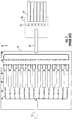
- FIG. 1 provides a schematic representation of a conventional LCP 10 having a feeder cable 12 enter the enclosure 14 of the LCP and a distribution cable 16 exit the LCP.
- each optical fiber 18 of the feeder cable 12 is connected to a splitter input 20 of a splitter 22.
- the fourteen optical fibers 18 are split into 432 optical fibers of a distribution cable 16 (thirteen optical fibers are split into thirty-two (1x32) and one optical fiber is split into sixteen (1x16) to provide the 432 distribution fibers).
- the splitter outputs 26 are selectively connected to the optical fibers 28 of the distribution cable using a subscriber termination field 30 (represented by the gap between the connectors of the splitter outputs 26 and the connectors of the optical fibers 28).
- the distribution cable 24 requires splicing of the distribution optical fibers 28 to one or more distribution cables 32, which in this exemplary embodiment are six distribution cables of 72 fibers each. Not only do the splices 34 require a significant amount of labor, as described above, but additional equipment is needed to provide the actual splice and to store the splices (such as a below grade handhole or other closure 36).
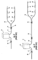
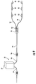
- the LCP of FIG. 1 is illustrated again in FIGS. 2 and 3 with additional components of the fiber optic distribution network shown.
- the feeder cable 12 typically must be spliced 40 prior to entering the enclosure 14 of the LCP 10, just as the distribution cable 16 is spliced 34 after exiting the enclosure of the LCP.
- This enables the LCPs 10 to be shipped into the field with stub feeder cable 12 and stub distribution cable 16 that are already routed, connected, and/or connectorized within the LCP.
- the distribution cable 16 is spliced 34 into distribution cables 32 that define a plurality of network access points 42 to which drop cables (not shown) may be optically connected.
- FIG. 3 represents a fiber optic distribution network wherein the network access points 42 must be located a relatively far distance from the LCP, thus requiring an additional distribution cable 44 to provide the additional length.
- the additional distribution cable 44 also requires additional splices 46.
- the various embodiments of the present invention address the above needs and achieve other advantages by providing local convergence points ("LCPs") comprising a plurality of preconnectorized multi-fiber ports that obviate the need to perform the splicing required by prior art LCPs. More specifically, the various embodiments of the present invention provide a plurality of preconnectorized multi-fiber ports within an interior cavity of the LCP, on an exterior wall of the LCP, and/or external to the LCP. Therefore, the LCPs of the present invention enable quick installation of an LCP in the field by enabling connection of the distribution cable(s) to the LCP without splicing.
- LCPs local convergence points
- One embodiment of the present invention provides an outside plant LCP in a fiber optic distribution network comprising at least one feeder cable and at least one distribution cable, wherein the LCP is adapted to provide optical connectivity between the feeder cable and the distribution cable.
- the LCP comprises an enclosure comprising an exterior wall and an interior cavity therein. Access to the interior cavity is provided through at least one door provided on the exterior wall.
- the LCP also includes a splitter within the interior cavity and in optical communication with at least one optical fiber of the feeder cable. The splitter is adapted to provide optical connectivity between the optical fiber of the feeder cable and a plurality of pigtails.
- the LCP further includes a subscriber termination field mounted within the interior cavity and comprising a plurality of adapters for selective optical connection between a pigtail of the plurality of pigtails and a subscriber fiber.
- the LCP also comprises a plurality of preconnectorized multi-fiber ports provided on a panel within the interior cavity, wherein the preconnectorized multi-fiber ports are in optical communication with a plurality of subscriber fibers.
- the plurality of preconnectorized multi-fiber ports of the LCP are adapted to receive a preconnectorized end of the distribution cable to thereby provide optical connectivity between the plurality of subscriber fibers and the distribution cable.
- the panel to which the preconnectorized multi-fiber ports are attached comprises a rear panel of the subscriber termination field.
- LCPs local convergence points
- FDHs fiber distribution hubs
- pedestals pedestals
- pole-mounted LCPs any other outside plant local convergence points optically connecting a feeder cable (or a portion of a feeder cable) to one or more distribution cables.
- the LCP 50 is adapted to provide optical connectivity between at least some of the optical fibers 52 of the feeder cable 54 and the optical fibers 56 of the one or more distribution cables 58. Some of the fibers (not shown) of the feeder cable 54 may pass through or bypass the LCP 50.
- the LCP 50 includes an enclosure 60 comprising an exterior wall, such as the side walls, top, and bottom of a fiber distribution hub, to provide one non-limiting example.
- the enclosure 60 does not necessarily need to be a complete enclosure and/or provide a seal or other barrier from the outside.
- the enclosure 60 of some embodiments of the present invention houses the internal components of the LCP 50.
- the enclosure 60 defines an interior cavity 62 therein, and the interior cavity is accessible through at least one door on at least one side of the LCP 50.
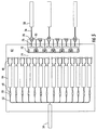
- fourteen splitter modules 64 to split the fourteen optical fibers 52 of the feeder cable 54 into 432 pigtails 66 connected to the splitter modules.
- the optical fibers 52 of the feeder cable 54 are connected to the splitter module inputs 68 by adapters 70.
- the plurality of pigtails 66 output from the splitter modules 64 are selectively inserted into adapters 72 of the subscriber termination field 74 mounted within the interior cavity.
- the subscriber termination field 74 comprises a plurality of adapters 72 (432 adapters in the embodiment of FIG. 4 ) that selectively optically connect the pigtails 66 to subscriber fibers 76 positioned on an opposite side of the subscriber termination field on which the pigtails are selectively connected to the adapters.
- the subscriber fibers 76 are optically connected to a plurality of preconnectorized multi-fiber ports 78. In the embodiment illustrated in FIG.
- the preconnectorized multi-fiber ports 78 include the adapter 80 needed for the preconnectorized multi-fiber port to receive a preconnectorized end of a distribution cable; however, in further embodiments of the present invention the preconnectorized multi-fiber ports include no adapters and/or other devices to conveniently provide connection of the subscriber fibers to the optical fibers of the distribution cable without splicing.
- the plurality of preconnectorized multi-fiber ports 78 of FIG. 4 includes thirty-six connectors comprising twelve fibers each.
- the plurality of preconnectorized multi-fiber ports 78 are provided on a panel within the interior cavity 62 of the LCP 50 such that the preconnectorized multi-fiber ports are in optical communication with the subscriber fibers 76.
- the panel on which the plurality of preconnectorized multi-fiber ports 78 are provided comprises a rear panel of the subscriber termination field 74.
- the panel on which the plurality of preconnectorized multi-fiber ports are provided is a different panel and/or a stand-alone panel within the enclosure, such that a technician must open the at least one door of the enclosure to gain access to one or more of the plurality of preconnectorized multi-fiber ports.
- the exterior wall provides convenient and secure routing of the distribution cable into the interior cavity of the enclosure.
- the preconnectorized multi-fiber ports of some embodiments of the present invention comprise at least one alignment and keying feature adapted for mechanical interaction with at least one alignment and keying feature of the preconnectorized end of the distribution cable.
- One particular example of such preconnectorized multi-fiber ports includes the connectors disclosed in U.S. Patent Application Serial Number 11/076,684 filed March 10, 2005 and assigned to the present assignee, the disclosure of which is hereby incorporated by reference in its entirety.
- Further embodiments of the present invention include alternative devices to orient, secure, and otherwise connect the preconnectorized multi-fiber ports to the preconnectorized ends of the distribution cable.
- the distribution cables 58 exit the enclosure 60 and preferably comprises a factory installed terminal system such that no splices are required along the distribution cable (including at an end opposite the preconnectorized end).
- a factory installed terminal system for the distribution cable 58 is provided in FIG. 6 , wherein the distribution cable comprises one or more tethers provided at mid span access locations 82 along the distribution cable.
- a non-limiting example of such a distribution cable is disclosed in U.S. Patent Application Serial Numbers 11/432,637 and 11/432,579 both filed May 11, 2006 and assigned to the present assignee, the disclosures of which are hereby incorporated by reference in their entirety.
- Still further embodiments of the present invention include alternative factory installed terminal systems for providing convenient connections to the distribution cable.
- the LCP 50 is substantially similar to the LCP of FIG. 4 ; however, the plurality of preconnectorized multi-fiber ports 78 are provided on the exterior wall of the enclosure 60. By providing the preconnectorized multi-fiber ports 78 on the exterior wall of the enclosure, a technician is able to connect the distribution cable without entering the interior cavity 62 of the LCP 50.
- 5 and 7 also includes only six preconnectorized multi-fiber ports 78 each comprising 72 fibers; however, further embodiments of the present invention comprise preconnectorized multi-fiber ports of alternative numbers of fibers, such as 4, 6, 8, 12, 16, 24, 32, 36, 48, 64, 72, and 96 to provide a few non-limiting examples.
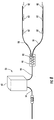
- the LCP includes an accumulator 90 outside the exterior wall of the enclosure 60.
- the accumulator is in optical connectivity with the subscriber termination field through an accumulator cable 94 comprising a plurality of subscriber fibers (which may or may not be in direct optical connectivity with the pigtails of the splitter).
- the accumulator cable 94 exits the interior cavity 62 of the enclosure 60 such that the accumulator is provided outside the enclosure, such that a technician is able to connect the distribution cables 58 without entering the enclosure.
- the accumulator 90 of the embodiment of FIG. 8 includes a plurality of preconnectorized multi-fiber ports 92 adapted to receive a preconnectorized end of the distribution cables 58 to thereby provide optical connectivity between the plurality of subscriber fibers and the distribution cable.
- the accumulator 90 of some embodiments of the present invention comprises a multi-port optical connection terminal, such as the type disclosed in U.S. Patent Application Serial Numbers 10/765,589 filed January 27, 2004 and granted as U.S. Patent No. 7,120,347 , which is assigned to the present assignee, the disclosure of which is hereby incorporated by reference in its entirety.
- Still further embodiments of the present invention comprise alternative accumulators to provide preconnectorized multi-fiber ports outside the enclosure of the LCP.
- a splice 96 is provide outside the LCP to splice the subscriber fibers 98 extending from the LCP 50 to the fibers of the accumulator cable 94 such that the subscriber fibers are in optical communication with the preconnectorized multi-fiber ports 92 of the accumulator 90 via a single splice.
- Alternative embodiments of the present invention provide a connector, rather than splice 96, to connect the accumulator to the LCP, while still further embodiments of the present invention provide still further devices and/or connections to provide improved connectivity between the LCP and the distribution cable(s).
- some embodiments of the present invention include various types of optical fibers which include, but are not limited to, low bend sensitivity optical fibers, bend optimized optical fibers, and bend insensitive optical fibers, all of which are referred to generically herein as "bend performance optical fiber.”
- bend performance optical fiber is microstructured optical fibers.
- Microstructured optical fibers comprise a core region and a cladding region surrounding the core region, the cladding region comprising an annular hole-containing region comprised of non-periodically disposed holes such that the optical fiber is capable of single mode transmission at one or more wavelengths in one or more operating wavelength ranges.
- the core region and cladding region provide improved bend resistance, and single mode operation at wavelengths preferably greater than or equal to 1500 nm, in some embodiments also greater than 1400 nm, in other embodiments also greater than 1260 nm.
- the optical fibers provide a mode field at a wavelength of 1310 nm preferably greater than 8.0 microns, more preferably between 8.0 and 10.0 microns.
- the microstructured optical fibers of various embodiments define single-mode transmission optical fiber and/or multi-mode transmission optical fiber.
- the microstructured optical fiber of some embodiments of the present invention comprises a core region disposed about a longitudinal centerline, and a cladding region surrounding the core region, the cladding region comprising an annular hole-containing region comprised of non-periodically disposed holes, wherein the annular hole-containing region has a maximum radial width of less than 12 microns, the annular hole-containing region has a regional void area percent of less than 30 percent, and the non-periodically disposed holes have a mean diameter of less than 1550 nm.
- non-periodically disposed or “non-periodic distribution” it is meant that when one takes a cross section (such as a cross section perpendicular to the longitudinal axis) of the optical fiber, the non-periodically disposed holes are randomly or non-periodically distributed across a portion of the fiber. Similar cross sections taken at different points along the length of the fiber will reveal different cross-sectional hole patterns, i.e., various cross sections will have different hole patterns, wherein the distributions of holes and sizes of holes do not match. That is, the voids or holes are non-periodic, i.e., they are not periodically disposed within the fiber structure. These holes are stretched (elongated) along the length (i.e. in a direction generally parallel to the longitudinal axis) of the optical fiber, but do not extend the entire length of the entire fiber for typical lengths of transmission fiber.
- the holes are formed such that greater than 95% of and preferably all of the holes exhibit a mean hole size in the cladding for the optical fiber which is less than 1550 nm, more preferably less than 775 nm, most preferably less than about 390 nm.
- the maximum diameter of the holes in the fiber be less than 7000 nm, more preferably less than 2000 nm, and even more preferably less than 1550 nm, and most preferably less than 775 nm.
- the fibers disclosed herein have fewer than 5000 holes, in some embodiments also fewer than 1000 holes, and in other embodiments the total number of holes is fewer than 500 holes in a given optical fiber perpendicular cross-section.
- the most preferred fibers will exhibit combinations of these characteristics.
- one particularly preferred embodiment of optical fiber would exhibit fewer than 200 holes in the optical fiber, the holes having a maximum diameter less than 1550 nm and a mean diameter less than 775 nm, although useful and bend resistant optical fibers can be achieved using larger and greater numbers of holes.
- the hole number, mean diameter, max diameter, and total void area percent of holes can all be calculated with the help of a scanning electron microscope at a magnification of about 800X and image analysis software, such as ImagePro, which is available from Media Cybernetics, Inc. of Silver Spring, Maryland, USA.
- the optical fiber disclosed herein may or may not include germania or fluorine to also adjust the refractive index of the core and or cladding of the optical fiber, but these dopants can also be avoided in the intermediate annular region and instead, the holes (in combination with any gas or gases that may be disposed within the holes) can be used to adjust the manner in which light is guided down the core of the fiber.
- the hole-containing region may consist of undoped (pure) silica, thereby completely avoiding the use of any dopants in the hole-containing region, to achieve a decreased refractive index, or the hole-containing region may comprise doped silica, e.g. fluorine-doped silica having a plurality of holes.
- the core region includes doped silica to provide a positive refractive index relative to pure silica, e.g. germania doped silica.
- the core region is preferably hole-free.
- the core region comprises a single core segment having a positive maximum refractive index relative to pure silica ⁇ 1 in %, and the single core segment extends from the centerline to a radius R 1 . In one set of embodiments, 0.30% ⁇ ⁇ 1 ⁇ 0.40%, and 3.0 ⁇ m ⁇ R 1 ⁇ 5.0 ⁇ m.
- the single core segment has a refractive index profile with an alpha shape, where alpha is 6 or more, and in some embodiments alpha is 8 or more.
- the inner annular hole-free region extends from the core region to a radius R 2 , wherein the inner annular hole-free region has a radial width W12, equal to R2 - R1, and W12 is greater than 1 ⁇ m.
- Radius R2 is preferably greater than 5 ⁇ m, more preferably greater than 6 ⁇ m.
- the intermediate annular hole-containing region extends radially outward from R2 to radius R3 and has a radial width W23, equal to R3 - R2.
- the outer annular region extends radially outward from R3 to radius R4.
- Radius R4 is the outermost radius of the silica portion of the optical fiber.
- One or more coatings may be applied to the external surface of the silica portion of the optical fiber, starting at R4, the outermost diameter or outermost periphery of the glass part of the fiber.
- the core region and the cladding region are preferably comprised of silica.
- the core region is preferably silica doped with one or more dopants.
- the core region is hole-free. While not necessary limited, the hole-containing region preferably has an inner radius R2 which is not more than 20 ⁇ m. In some embodiments, R2 is not less than 10 ⁇ m and not greater than 20 ⁇ m.
- R2 is not less than 10 ⁇ m and not greater than 18 ⁇ m. In other embodiments, R2 is not less than 10 ⁇ m and not greater than 14 ⁇ m.
- the hole-containing region preferably has a radial width W23 which is not less than 0.5 ⁇ m. In some embodiments, W23 is not less than 0.5 ⁇ m and not greater than 20 ⁇ m. In other embodiments, W23 is not less than 2 ⁇ m and not greater than 12 ⁇ m. In other embodiments, W23 is not less than 2 ⁇ m and not greater than 10 ⁇ m.
- Such fiber can be made to exhibit a fiber cutoff of less than 1400 nm, more preferably less than 1310 nm, a 20 mm macrobend induced loss of less than 0.5 dB/turn, preferably less than 0.1 dB/turn, more preferably less than 0.05 dB/turn, even more preferably less than 0.03 dB/turn , and still more preferably less than 0.02 dB/turn, a 12 mm macrobend induced loss of less than 1 dB/turn, preferably less than 0.5 dB/turn, more preferably less than 0.2 dB/turn, and even more preferably less than 0.1 dB/turn, and still even more preferably less than 0.05 dB/turn, and a 8 mm macrobend induced loss of less than 5 dB/turn, preferably less than 1 dB/turn, more preferably less than 0.5 dB/turn, and even more preferably less than 0.2 dB/turn and still even more preferably less than
- microstructured optical fibers of additional embodiments of the present invention are described more fully in pending U.S. patent application serial number 11/583,098 filed October 18, 2006 , and provisional U.S. patent application serial numbers 60/817,863 filed June 30, 2006 ; 60/817,721 filed June 30, 2006 ; 60/841,458 filed August 31, 2006 ; and 60/841,490 filed August 31, 2006 ; all of which are assigned to Corning Incorporated and the disclosures of which are incorporated by reference herein.
Abstract
Description
- The present invention is related to fiber optic networks, and more particularly, to fiber optic local convergence points having preconnectorized connections.
- Fiber optic distribution networks typically include a central office from which optical signals originate and are transmitted to a number of subscribers via the network. Feeder cables usually extend from the central office to one or more local convergence points. At the local convergence point the optical signals from the central office are often split from each of the optical fibers of the feeder cable to a plurality (such as 16, 32, or 64) of optical fibers of a distribution cable. The optical fibers of the distribution cable are then routed to a network access point where the optical fibers are connected, spliced, or otherwise placed in optical communication with drop cables that typically are routed to a subscriber's premises, such as a home or business. In addition to providing a splitter in the local convergence point ("LCP"), LCPs often include a subscriber termination field comprising a plurality of adapters to selectively connect a pigtail extending from a splitter to an optical fiber of the distribution cable, thereby enabling a technician to selectively activate a subscriber by simply plugging a pigtail into a particular adapter (and selectively deactivate a subscriber by removing the pigtail).
- Installation of such LCPs is often very time-consuming given the number of splices a technician must perform when optically connecting the LCP to the feeder cable and/or distribution cable. For example, an LCP having 432 distribution outputs requires splicing of all 432 fibers of the distribution cable(s), which may take a technician over twenty-two hours to splice. Even if optical fiber ribbon cable is utilized, it may take a technician over eight hours to splice the 432 fibers of the distribution cable.
FIG. 1 provides a schematic representation of aconventional LCP 10 having afeeder cable 12 enter theenclosure 14 of the LCP and adistribution cable 16 exit the LCP. Within the LCP, eachoptical fiber 18 of thefeeder cable 12 is connected to asplitter input 20 of asplitter 22. The fourteenoptical fibers 18 are split into 432 optical fibers of a distribution cable 16 (thirteen optical fibers are split into thirty-two (1x32) and one optical fiber is split into sixteen (1x16) to provide the 432 distribution fibers). Thesplitter outputs 26 are selectively connected to theoptical fibers 28 of the distribution cable using a subscriber termination field 30 (represented by the gap between the connectors of thesplitter outputs 26 and the connectors of the optical fibers 28). However, the distribution cable 24 requires splicing of the distributionoptical fibers 28 to one ormore distribution cables 32, which in this exemplary embodiment are six distribution cables of 72 fibers each. Not only do thesplices 34 require a significant amount of labor, as described above, but additional equipment is needed to provide the actual splice and to store the splices (such as a below grade handhole or other closure 36). - The LCP of
FIG. 1 is illustrated again inFIGS. 2 and 3 with additional components of the fiber optic distribution network shown. Thefeeder cable 12 typically must be spliced 40 prior to entering theenclosure 14 of theLCP 10, just as thedistribution cable 16 is spliced 34 after exiting the enclosure of the LCP. This enables theLCPs 10 to be shipped into the field withstub feeder cable 12 andstub distribution cable 16 that are already routed, connected, and/or connectorized within the LCP. As shown inFIG. 2 , thedistribution cable 16 is spliced 34 intodistribution cables 32 that define a plurality ofnetwork access points 42 to which drop cables (not shown) may be optically connected.FIG. 3 represents a fiber optic distribution network wherein thenetwork access points 42 must be located a relatively far distance from the LCP, thus requiring anadditional distribution cable 44 to provide the additional length. Theadditional distribution cable 44 also requiresadditional splices 46. - Therefore, a need exists for improved LCPs and fiber optic distribution networks that do not require splicing of the distribution cable and/or feeder cable. Elimination of such splicing would reduce the time, skill level, and expense of performing a large number of splices and eliminate the equipment needed for such splicing.
- The various embodiments of the present invention address the above needs and achieve other advantages by providing local convergence points ("LCPs") comprising a plurality of preconnectorized multi-fiber ports that obviate the need to perform the splicing required by prior art LCPs. More specifically, the various embodiments of the present invention provide a plurality of preconnectorized multi-fiber ports within an interior cavity of the LCP, on an exterior wall of the LCP, and/or external to the LCP. Therefore, the LCPs of the present invention enable quick installation of an LCP in the field by enabling connection of the distribution cable(s) to the LCP without splicing.
- One embodiment of the present invention provides an outside plant LCP in a fiber optic distribution network comprising at least one feeder cable and at least one distribution cable, wherein the LCP is adapted to provide optical connectivity between the feeder cable and the distribution cable. The LCP comprises an enclosure comprising an exterior wall and an interior cavity therein. Access to the interior cavity is provided through at least one door provided on the exterior wall. The LCP also includes a splitter within the interior cavity and in optical communication with at least one optical fiber of the feeder cable. The splitter is adapted to provide optical connectivity between the optical fiber of the feeder cable and a plurality of pigtails. The LCP further includes a subscriber termination field mounted within the interior cavity and comprising a plurality of adapters for selective optical connection between a pigtail of the plurality of pigtails and a subscriber fiber. The LCP also comprises a plurality of preconnectorized multi-fiber ports provided on a panel within the interior cavity, wherein the preconnectorized multi-fiber ports are in optical communication with a plurality of subscriber fibers. The plurality of preconnectorized multi-fiber ports of the LCP are adapted to receive a preconnectorized end of the distribution cable to thereby provide optical connectivity between the plurality of subscriber fibers and the distribution cable. In some embodiments of the present invention the panel to which the preconnectorized multi-fiber ports are attached comprises a rear panel of the subscriber termination field.
- Further embodiments of the present invention provide the plurality of preconnectorized multi-fiber ports on an exterior wall of the LCP. Still further embodiments of the present invention provide an accumulator outside the exterior wall of the enclosure of the LCP. The accumulator includes the plurality of preconnectorized multi-fiber ports. Therefore, the LCPs of various embodiments of the present invention provide preconnectorized multi-fiber ports to facilitate convenient optical connection of one or more distribution cables to the LCP. Furthermore, certain embodiments of the present invention allow selective optical connection of distribution cables to the LCPs without the need for technicians to enter the LCP, thus reducing the risk of unintentional damage within the interior of the LCP and simplifying connection of the distribution cable.
- Having thus described the invention in general terms, reference will now be made to the accompanying drawings, which are not necessarily drawn to scale and are meant to be illustrative and not limiting, and wherein:
-
FIG. 1 is a schematic view of a prior art LCP, illustrating the splices required for the distribution cable; -
FIG. 2 is a perspective schematic view of the prior art LCP ofFIG. 1 , further illustrating the splicing of the feeder cable and distribution cable; -
FIG. 3 is a perspective schematic view of the prior art LCP ofFIG. 1 , illustrating additional splicing of the distribution cable; -
FIG. 4 is a schematic view of an LCP in accordance with one embodiment of the present invention, illustrating the preconnectorized multi-fiber ports for use with thirty-six 12 fiber distribution cables; -
FIG. 5 is a schematic view of an LCP in accordance with another embodiment of the present invention, illustrating the preconnectorized multi-fiber ports for use with six 72 fiber distribution cables; -
FIG. 6 is a perspective schematic view of an LCP in accordance with yet another embodiment of the present invention, illustrating the preconnectorized multi-fiber ports provided on a panel within the interior cavity of the LCP; -
FIG. 7 is a perspective schematic view of an LCP in accordance with yet another embodiment of the present invention, illustrating the preconnectorized multi-fiber ports provided on an exterior wall of the LCP; -
FIG. 8 is a perspective schematic view of an LCP in accordance with yet another embodiment of the present invention, illustrating the preconnectorized multi-fiber ports provided on an accumulator outside the exterior wall of the LCP; and -
FIG. 9 is a perspective schematic view of an LCP in accordance with yet another embodiment of the present invention, illustrating the preconnectorized multi-fiber ports provided on an accumulator outside the exterior wall of the LCP, wherein the accumulator cable includes splices. - The present invention now will be described more fully hereinafter with reference to the accompanying drawings, in which some, but not all embodiments of the invention are shown. Indeed, the invention may be embodied in many different forms and should not be construed as limited to the embodiments set forth herein; rather, these embodiments are provided so that this disclosure will satisfy applicable legal requirements. Although apparatus and methods for providing preconnectorized multi-fiber ports with a local convergence point are described and shown in the accompanying drawings with regard to specific types of components, orientations, and configurations, it is envisioned that the functionality of the various apparatus of the present invention may be applied to any now known or hereafter devised local convergence points in which it is desired to provide preconnectorized multi-fiber ports. Like numbers refer to like elements throughout.
- With reference to
FIGS. 4-9 , a number of local convergence points ("LCPs") in accordance with various embodiments of the present invention are illustrated. The LCPs of the present invention are intended to encompass fiber distribution hubs ("FDHs"), pedestals, pole-mounted LCPs, and any other outside plant local convergence points optically connecting a feeder cable (or a portion of a feeder cable) to one or more distribution cables. - Turning now to the embodiment of
FIG. 4 , anoutside plant LCP 50 in a fiber optic distribution network is illustrated. The LCP 50 is adapted to provide optical connectivity between at least some of theoptical fibers 52 of thefeeder cable 54 and theoptical fibers 56 of the one ormore distribution cables 58. Some of the fibers (not shown) of thefeeder cable 54 may pass through or bypass theLCP 50. TheLCP 50 includes anenclosure 60 comprising an exterior wall, such as the side walls, top, and bottom of a fiber distribution hub, to provide one non-limiting example. Theenclosure 60 does not necessarily need to be a complete enclosure and/or provide a seal or other barrier from the outside. Theenclosure 60 of some embodiments of the present invention houses the internal components of theLCP 50. Theenclosure 60 defines aninterior cavity 62 therein, and the interior cavity is accessible through at least one door on at least one side of theLCP 50. Within theenclosure 60 of theLCP 50 ofFIG. 4 is provided fourteensplitter modules 64 to split the fourteenoptical fibers 52 of thefeeder cable 54 into 432pigtails 66 connected to the splitter modules. Theoptical fibers 52 of thefeeder cable 54 are connected to thesplitter module inputs 68 byadapters 70. - The plurality of
pigtails 66 output from thesplitter modules 64 are selectively inserted intoadapters 72 of thesubscriber termination field 74 mounted within the interior cavity. Thesubscriber termination field 74 comprises a plurality of adapters 72 (432 adapters in the embodiment ofFIG. 4 ) that selectively optically connect thepigtails 66 tosubscriber fibers 76 positioned on an opposite side of the subscriber termination field on which the pigtails are selectively connected to the adapters. Thesubscriber fibers 76 are optically connected to a plurality of preconnectorizedmulti-fiber ports 78. In the embodiment illustrated inFIG. 4 , the preconnectorizedmulti-fiber ports 78 include theadapter 80 needed for the preconnectorized multi-fiber port to receive a preconnectorized end of a distribution cable; however, in further embodiments of the present invention the preconnectorized multi-fiber ports include no adapters and/or other devices to conveniently provide connection of the subscriber fibers to the optical fibers of the distribution cable without splicing. - The plurality of preconnectorized
multi-fiber ports 78 ofFIG. 4 includes thirty-six connectors comprising twelve fibers each. The plurality of preconnectorizedmulti-fiber ports 78 are provided on a panel within theinterior cavity 62 of theLCP 50 such that the preconnectorized multi-fiber ports are in optical communication with thesubscriber fibers 76. In the exemplary embodiment ofFIG. 4 , the panel on which the plurality of preconnectorizedmulti-fiber ports 78 are provided comprises a rear panel of thesubscriber termination field 74. In further embodiments of the present invention the panel on which the plurality of preconnectorized multi-fiber ports are provided is a different panel and/or a stand-alone panel within the enclosure, such that a technician must open the at least one door of the enclosure to gain access to one or more of the plurality of preconnectorized multi-fiber ports. In such embodiments having the plurality of preconnectorized multi-fiber ports within the enclosure, the exterior wall provides convenient and secure routing of the distribution cable into the interior cavity of the enclosure. - The preconnectorized multi-fiber ports of some embodiments of the present invention comprise at least one alignment and keying feature adapted for mechanical interaction with at least one alignment and keying feature of the preconnectorized end of the distribution cable. One particular example of such preconnectorized multi-fiber ports includes the connectors disclosed in
U.S. Patent Application Serial Number 11/076,684 filed March 10, 2005 and assigned to the present assignee, the disclosure of which is hereby incorporated by reference in its entirety. Further embodiments of the present invention include alternative devices to orient, secure, and otherwise connect the preconnectorized multi-fiber ports to the preconnectorized ends of the distribution cable. - Referring again to
FIG. 4 , thedistribution cables 58 exit theenclosure 60 and preferably comprises a factory installed terminal system such that no splices are required along the distribution cable (including at an end opposite the preconnectorized end). An example of a factory installed terminal system for thedistribution cable 58 is provided inFIG. 6 , wherein the distribution cable comprises one or more tethers provided at midspan access locations 82 along the distribution cable. A non-limiting example of such a distribution cable is disclosed inU.S. Patent Application Serial Numbers 11/432,637 and11/432,579 both filed May 11, 2006 - Turning now to the exemplary embodiment of
FIGS. 5 and7 , theLCP 50 is substantially similar to the LCP ofFIG. 4 ; however, the plurality of preconnectorizedmulti-fiber ports 78 are provided on the exterior wall of theenclosure 60. By providing the preconnectorizedmulti-fiber ports 78 on the exterior wall of the enclosure, a technician is able to connect the distribution cable without entering theinterior cavity 62 of theLCP 50. TheLCP 50 ofFIGS. 5 and7 also includes only six preconnectorizedmulti-fiber ports 78 each comprising 72 fibers; however, further embodiments of the present invention comprise preconnectorized multi-fiber ports of alternative numbers of fibers, such as 4, 6, 8, 12, 16, 24, 32, 36, 48, 64, 72, and 96 to provide a few non-limiting examples. - Turning now to the
LCP 50 ofFIG. 8 , the LCP includes anaccumulator 90 outside the exterior wall of theenclosure 60. The accumulator is in optical connectivity with the subscriber termination field through anaccumulator cable 94 comprising a plurality of subscriber fibers (which may or may not be in direct optical connectivity with the pigtails of the splitter). Theaccumulator cable 94 exits theinterior cavity 62 of theenclosure 60 such that the accumulator is provided outside the enclosure, such that a technician is able to connect thedistribution cables 58 without entering the enclosure. - The
accumulator 90 of the embodiment ofFIG. 8 includes a plurality of preconnectorizedmulti-fiber ports 92 adapted to receive a preconnectorized end of thedistribution cables 58 to thereby provide optical connectivity between the plurality of subscriber fibers and the distribution cable. Theaccumulator 90 of some embodiments of the present invention comprises a multi-port optical connection terminal, such as the type disclosed inU.S. Patent Application Serial Numbers 10/765,589 filed January 27, 2004U.S. Patent No. 7,120,347 , which is assigned to the present assignee, the disclosure of which is hereby incorporated by reference in its entirety. Still further embodiments of the present invention comprise alternative accumulators to provide preconnectorized multi-fiber ports outside the enclosure of the LCP. - Turning now to the
LCP 50 ofFIG. 9 , asplice 96 is provide outside the LCP to splice thesubscriber fibers 98 extending from theLCP 50 to the fibers of theaccumulator cable 94 such that the subscriber fibers are in optical communication with the preconnectorizedmulti-fiber ports 92 of theaccumulator 90 via a single splice. Alternative embodiments of the present invention provide a connector, rather thansplice 96, to connect the accumulator to the LCP, while still further embodiments of the present invention provide still further devices and/or connections to provide improved connectivity between the LCP and the distribution cable(s). - With regards to the optical fibers used within the LCP, some embodiments of the present invention include various types of optical fibers which include, but are not limited to, low bend sensitivity optical fibers, bend optimized optical fibers, and bend insensitive optical fibers, all of which are referred to generically herein as "bend performance optical fiber." One specific example of bend performance optical fiber is microstructured optical fibers. Microstructured optical fibers comprise a core region and a cladding region surrounding the core region, the cladding region comprising an annular hole-containing region comprised of non-periodically disposed holes such that the optical fiber is capable of single mode transmission at one or more wavelengths in one or more operating wavelength ranges. The core region and cladding region provide improved bend resistance, and single mode operation at wavelengths preferably greater than or equal to 1500 nm, in some embodiments also greater than 1400 nm, in other embodiments also greater than 1260 nm. The optical fibers provide a mode field at a wavelength of 1310 nm preferably greater than 8.0 microns, more preferably between 8.0 and 10.0 microns. The microstructured optical fibers of various embodiments define single-mode transmission optical fiber and/or multi-mode transmission optical fiber.
- The microstructured optical fiber of some embodiments of the present invention comprises a core region disposed about a longitudinal centerline, and a cladding region surrounding the core region, the cladding region comprising an annular hole-containing region comprised of non-periodically disposed holes, wherein the annular hole-containing region has a maximum radial width of less than 12 microns, the annular hole-containing region has a regional void area percent of less than 30 percent, and the non-periodically disposed holes have a mean diameter of less than 1550 nm.
- By "non-periodically disposed" or "non-periodic distribution", it is meant that when one takes a cross section (such as a cross section perpendicular to the longitudinal axis) of the optical fiber, the non-periodically disposed holes are randomly or non-periodically distributed across a portion of the fiber. Similar cross sections taken at different points along the length of the fiber will reveal different cross-sectional hole patterns, i.e., various cross sections will have different hole patterns, wherein the distributions of holes and sizes of holes do not match. That is, the voids or holes are non-periodic, i.e., they are not periodically disposed within the fiber structure. These holes are stretched (elongated) along the length (i.e. in a direction generally parallel to the longitudinal axis) of the optical fiber, but do not extend the entire length of the entire fiber for typical lengths of transmission fiber.
- For a variety of applications, it is desirable for the holes to be formed such that greater than 95% of and preferably all of the holes exhibit a mean hole size in the cladding for the optical fiber which is less than 1550 nm, more preferably less than 775 nm, most preferably less than about 390 nm. Likewise, it is preferable that the maximum diameter of the holes in the fiber be less than 7000 nm, more preferably less than 2000 nm, and even more preferably less than 1550 nm, and most preferably less than 775 nm. In some embodiments, the fibers disclosed herein have fewer than 5000 holes, in some embodiments also fewer than 1000 holes, and in other embodiments the total number of holes is fewer than 500 holes in a given optical fiber perpendicular cross-section. Of course, the most preferred fibers will exhibit combinations of these characteristics. Thus, for example, one particularly preferred embodiment of optical fiber would exhibit fewer than 200 holes in the optical fiber, the holes having a maximum diameter less than 1550 nm and a mean diameter less than 775 nm, although useful and bend resistant optical fibers can be achieved using larger and greater numbers of holes. The hole number, mean diameter, max diameter, and total void area percent of holes can all be calculated with the help of a scanning electron microscope at a magnification of about 800X and image analysis software, such as ImagePro, which is available from Media Cybernetics, Inc. of Silver Spring, Maryland, USA.
- The optical fiber disclosed herein may or may not include germania or fluorine to also adjust the refractive index of the core and or cladding of the optical fiber, but these dopants can also be avoided in the intermediate annular region and instead, the holes (in combination with any gas or gases that may be disposed within the holes) can be used to adjust the manner in which light is guided down the core of the fiber. The hole-containing region may consist of undoped (pure) silica, thereby completely avoiding the use of any dopants in the hole-containing region, to achieve a decreased refractive index, or the hole-containing region may comprise doped silica, e.g. fluorine-doped silica having a plurality of holes.
- In one set of embodiments, the core region includes doped silica to provide a positive refractive index relative to pure silica, e.g. germania doped silica. The core region is preferably hole-free. In some embodiments, the core region comprises a single core segment having a positive maximum refractive index relative to pure silica Δ1 in %, and the single core segment extends from the centerline to a radius R1. In one set of embodiments, 0.30% < Δ1 < 0.40%, and 3.0 µm < R1 < 5.0 µm. In some embodiments, the single core segment has a refractive index profile with an alpha shape, where alpha is 6 or more, and in some embodiments alpha is 8 or more. In some embodiments, the inner annular hole-free region extends from the core region to a radius R2, wherein the inner annular hole-free region has a radial width W12, equal to R2 - R1, and W12 is greater than 1 µm. Radius R2 is preferably greater than 5 µm, more preferably greater than 6 µm. The intermediate annular hole-containing region extends radially outward from R2 to radius R3 and has a radial width W23, equal to R3 - R2. The outer annular region extends radially outward from R3 to radius R4. Radius R4 is the outermost radius of the silica portion of the optical fiber. One or more coatings may be applied to the external surface of the silica portion of the optical fiber, starting at R4, the outermost diameter or outermost periphery of the glass part of the fiber. The core region and the cladding region are preferably comprised of silica. The core region is preferably silica doped with one or more dopants. Preferably, the core region is hole-free. While not necessary limited, the hole-containing region preferably has an inner radius R2 which is not more than 20 µm. In some embodiments, R2 is not less than 10 µm and not greater than 20 µm. In other embodiments, R2 is not less than 10 µm and not greater than 18 µm. In other embodiments, R2 is not less than 10 µm and not greater than 14 µm. Again, while not being limited to any particular width, the hole-containing region preferably has a radial width W23 which is not less than 0.5 µm. In some embodiments, W23 is not less than 0.5 µm and not greater than 20 µm. In other embodiments, W23 is not less than 2 µm and not greater than 12 µm. In other embodiments, W23 is not less than 2 µm and not greater than 10 µm.
- Such fiber can be made to exhibit a fiber cutoff of less than 1400 nm, more preferably less than 1310 nm, a 20 mm macrobend induced loss of less than 0.5 dB/turn, preferably less than 0.1 dB/turn, more preferably less than 0.05 dB/turn, even more preferably less than 0.03 dB/turn , and still more preferably less than 0.02 dB/turn, a 12 mm macrobend induced loss of less than 1 dB/turn, preferably less than 0.5 dB/turn, more preferably less than 0.2 dB/turn, and even more preferably less than 0.1 dB/turn, and still even more preferably less than 0.05 dB/turn, and a 8 mm macrobend induced loss of less than 5 dB/turn, preferably less than 1 dB/turn, more preferably less than 0.5 dB/turn, and even more preferably less than 0.2 dB/turn and still even more preferably less than 0.1 dB/turn. An example of a suitable fiber is a fiber comprising a core region surrounded by a cladding region which comprises randomly disposed voids which are contained within an annular region spaced from the core and positioned to be effective to guide light along the core region.
- Additional features of the microstructured optical fibers of additional embodiments of the present invention are described more fully in pending
U.S. patent application serial number 11/583,098 filed October 18, 2006 U.S. patent application serial numbers 60/817,863 filed June 30, 200660/817,721 filed June 30, 2006 60/841,458 filed August 31, 2006 60/841,490 filed August 31, 2006 - Many modifications and other embodiments of the invention set forth herein will come to mind to one skilled in the art to which the invention pertains having the benefit of the teachings presented in the foregoing descriptions and the associated drawings. Therefore, it is to be understood that the invention is not to be limited to the specific embodiments disclosed and that modifications and other embodiments are intended to be included within the scope of the appended claims. It is intended that the present invention cover the modifications and variations of this invention provided they come within the scope of the appended claims and their equivalents. Although specific terms are employed herein, they are used in a generic and descriptive sense only and not for purposes of limitation.
Claims (14)
- An outside plant local convergence point in a fiber optic distribution network comprising at least one feeder cable and at least one distribution cable, wherein the local convergence point is adapted to provide optical connectivity between the feeder cable and the distribution cable, the local convergence point comprising:an enclosure comprising an exterior wall and an interior cavity therein, wherein access to the interior cavity is provided through at least one door;a splitter mounted within the interior cavity and in optical communication with at least one optical fiber of the feeder cable and adapted to provide optical connectivity between the optical fiber of the feeder cable and a plurality of pigtails;a subscriber termination field mounted within the interior cavity and comprising a plurality of adapters for selective optical connection between a pigtail of the plurality of pigtails and a subscriber fiber; andan accumulator outside the exterior wall of the enclosure and in optical connectivity with the subscriber termination field through an accumulator cable comprising a plurality of subscriber fibers, wherein the accumulator cable exits the interior cavity of the enclosure and wherein the accumulator comprises a plurality of preconnectorized multi-fiber ports adapted to receive a preconnectorized end of the distribution cable to thereby provide optical connectivity between the plurality of subscriber fibers and the distribution cable.
- A local convergence point according to Claim 1, wherein the subscriber fibers are in direct optical communication with the preconnectorized multi-fiber ports of the accumulator without any intermediate splices or connectors.
- A local convergence point according to Claim 1 or 2, wherein the subscriber fibers are in optical communication with the preconnectorized multi-fiber ports of the accumulator via a single splice.
- A local convergence point according to one of Claims 1-3, wherein the subscriber fibers are in optical communication with the preconnectorized multi-fiber ports of the accumulator via a single connection.
- A local convergence point according to one of Claims 1-4, wherein the preconnectorized multi-fiber ports comprise at least one of the following numbers of fibers: 4, 6, 8, 12, 16, 24, 32, 36, 48, 64, 72, and 96.
- A local convergence point according to one of Claims 1-5, wherein the preconnectorized multi-fiber ports include at least one alignment and keying feature adapted for mechanical interaction with at least one alignment and keying feature of the preconnectorized end of the distribution cable.
- A local convergence point according to one of Claims 1-6 wherein the plurality of preconnectorized multi-fiber ports are adapted to receive preconnectorized ends of distribution cables including one or more tethers provided at mid span access locations along the distribution cable.
- A local convergence point according to one of Claims 1-7, wherein at least one optical fiber within the enclosure comprises a microstructured optical fiber comprising a core region and a cladding region surrounding the core region, the cladding region comprising an annular hole-containing region comprised of non-periodically disposed holes.
- An outside plant local convergence point in a fiber optic distribution network comprising at least one feeder cable and at least one distribution cable, wherein the local convergence point is adapted to provide optical connectivity between the feeder cable and the distribution cable, the local convergence point comprising:an enclosure comprising an exterior wall and an interior cavity therein, wherein access to the interior cavity is provided through at least one door;a splitter mounted within the interior cavity and in optical communication with at least one optical fiber of the feeder cable and adapted to provide optical connectivity between the optical fiber of the feeder cable and a plurality of pigtails;a subscriber termination field mounted within the interior cavity and comprising a plurality of adapters for selective optical connection between a pigtail of the plurality of pigtails and a subscriber fiber; anda plurality of preconnectorized multi-fiber ports provided on the exterior wall of the enclosure, wherein the preconnectorized multi-fiber ports are in optical communication with a plurality of subscriber fibers;wherein the plurality of preconnectorized multi-fiber ports are adapted to receive a preconnectorized end of the distribution cable to thereby provide optical connectivity between the plurality of subscriber fibers and the distribution cable.
- A local convergence point according to Claim 9, wherein the preconnectorized multi-fiber ports comprise at least one of the following numbers of fibers: 4, 6, 8, 12, 16, 24, 32, 36, 48, 64, 72, and 96.
- A local convergence point according to Claim 9 or 10, wherein the preconnectorized multi-fiber ports include at least one alignment and keying feature adapted for mechanical interaction with at least one alignment and keying feature of the preconnectorized end of the distribution cable.
- A local convergence point according to one of Claims 9-11, wherein the plurality of preconnectorized multi-fiber ports are adapted to receive preconnectorized ends of distribution cables including one or more tethers provided at mid span access locations along the distribution cable.
- A local convergence point according to one of Claims 9-12, wherein the feeder cable is spliced to at least one stub cable in optical communication with the splitter.
- A local convergence point according to one of Claims 9-13, wherein at least one optical fiber within the enclosure comprises a microstructured optical fiber comprising a core region and a cladding region surrounding the core region, the cladding region comprising an annular hole-containing region comprised of non-periodically disposed holes.
Applications Claiming Priority (2)
| Application Number | Priority Date | Filing Date | Title |
|---|---|---|---|
| US11/643,344 US7519258B2 (en) | 2006-12-21 | 2006-12-21 | Preconnectorized fiber optic local convergence points |
| EP07863199A EP2095165A2 (en) | 2006-12-21 | 2007-12-20 | Preconnectorized fiber optic local convergence points |
Related Parent Applications (1)
| Application Number | Title | Priority Date | Filing Date |
|---|---|---|---|
| EP07863199A Division EP2095165A2 (en) | 2006-12-21 | 2007-12-20 | Preconnectorized fiber optic local convergence points |
Publications (2)
| Publication Number | Publication Date |
|---|---|
| EP3081971A2 true EP3081971A2 (en) | 2016-10-19 |
| EP3081971A3 EP3081971A3 (en) | 2017-01-04 |
Family
ID=39321059
Family Applications (2)
| Application Number | Title | Priority Date | Filing Date |
|---|---|---|---|
| EP07863199A Withdrawn EP2095165A2 (en) | 2006-12-21 | 2007-12-20 | Preconnectorized fiber optic local convergence points |
| EP16156927.2A Withdrawn EP3081971A3 (en) | 2006-12-21 | 2007-12-20 | Preconnectorized fiber optic local convergence points |
Family Applications Before (1)
| Application Number | Title | Priority Date | Filing Date |
|---|---|---|---|
| EP07863199A Withdrawn EP2095165A2 (en) | 2006-12-21 | 2007-12-20 | Preconnectorized fiber optic local convergence points |
Country Status (4)
| Country | Link |
|---|---|
| US (2) | US7519258B2 (en) |
| EP (2) | EP2095165A2 (en) |
| AU (1) | AU2007338737B2 (en) |
| WO (1) | WO2008079329A2 (en) |
Families Citing this family (27)
| Publication number | Priority date | Publication date | Assignee | Title |
|---|---|---|---|---|
| US7623749B2 (en) * | 2005-08-30 | 2009-11-24 | Adc Telecommunications, Inc. | Fiber distribution hub with modular termination blocks |
| US7349616B1 (en) * | 2007-01-12 | 2008-03-25 | Corning Cable Systems Llc | Fiber optic local convergence points for multiple dwelling units |
| US7400814B1 (en) | 2007-01-13 | 2008-07-15 | Furukawa Electric North America, Inc. | Wall-mountable optical fiber and cable management apparatus |
| US9188759B2 (en) * | 2008-10-14 | 2015-11-17 | Corning Cable Systems Llc | Optical connection terminal having port mapping scheme |
| US8873967B2 (en) * | 2008-10-17 | 2014-10-28 | Corning Cable Systems Llc | Optical interconnection modules for hybrid electrical-optical networks |
| US9482840B2 (en) * | 2009-05-27 | 2016-11-01 | Corning Cable Systems Llc | Port mapping for series connected fiber optic terminals |
| US8251591B2 (en) | 2009-06-17 | 2012-08-28 | Corning Cable Systems | Optical interconnection assemblies and systems for high-speed data-rate optical transport systems |
| US8649649B2 (en) | 2010-03-03 | 2014-02-11 | Adc Telecommunications, Inc. | Fiber distribution hub with connectorized stub cables |
| US20110235986A1 (en) * | 2010-03-24 | 2011-09-29 | Adc Telecommunications, Inc. | Optical fiber drawer with connectorized stub cable |
| US9097873B2 (en) | 2010-04-14 | 2015-08-04 | Corning Cable Systems Llc | Port mapping in fiber optic network devices |
| US9377597B2 (en) * | 2010-06-02 | 2016-06-28 | Commscope Technologies Llc | Aggregator for a switch rack system |
| FR2961943A1 (en) * | 2010-06-29 | 2011-12-30 | Neva Finance Conseil | Cross connection device for carrying out interconnection between connector elements for e.g. computer network in building, has optical fiber whose one end is connected to switches/cabinets to which equipments are connected by copper wires |
| US8961035B2 (en) | 2010-08-02 | 2015-02-24 | Adc Telecommunications, Inc. | Architecture for a fiber optic network |
| WO2013003195A1 (en) * | 2011-06-30 | 2013-01-03 | Corning Cable Systems Llc | Multi-port optical connection terminal assemblies supporting optical signal splitting, and related terminals and methods |
| US20130216187A1 (en) | 2011-08-17 | 2013-08-22 | Douglas Ferris Dowling | Distributed passive optical networks |
| US20130058609A1 (en) * | 2011-09-02 | 2013-03-07 | Elli Makrides-Saravanos | Attenuated splitter module for low count output channels and related assemblies and methods |
| US9348096B2 (en) | 2012-03-30 | 2016-05-24 | Commscope Technologies Llc | Passive distribution system using fiber indexing |
| CA3080382C (en) * | 2012-03-30 | 2023-09-12 | Adc Telecommunications, Inc. | Deploying optical fibers using indexing terminals |
| US9097874B2 (en) | 2012-07-25 | 2015-08-04 | Corning Optical Communications LLC | Polarity configurations for parallel optics data transmission, and related apparatuses, components, systems, and methods |
| US9057863B2 (en) | 2012-07-25 | 2015-06-16 | Corning Cable Systems Llc | Polarity scheme for parallel-optics data transmission |
| WO2014070511A1 (en) * | 2012-10-29 | 2014-05-08 | Adc Telecommunications, Inc. | System for testing passive optical lines |
| WO2014134154A1 (en) | 2013-02-26 | 2014-09-04 | Tyco Electronics Corporation | High density splitter aggregation module |
| WO2015028433A1 (en) * | 2013-08-24 | 2015-03-05 | Tyco Electronics Raychem Bvba | Ruggedized fiber optic connectors and connection systems |
| EP3205034A4 (en) | 2014-10-06 | 2018-06-27 | ADC Telecommunications Inc. | Facilitating installation of fiber optic networks |
| US9885845B2 (en) | 2015-01-15 | 2018-02-06 | Commscope, Inc. Of North Carolina | Module and assembly for fiber optic interconnections |
| US10606009B2 (en) * | 2015-12-01 | 2020-03-31 | CommScope Connectivity Belgium BVBA | Cable distribution system with fan out devices |
| WO2020214762A1 (en) * | 2019-04-16 | 2020-10-22 | Corning Research & Development Corporation | Preconnectorized cable assemblies for indoor/outdoor/datacenter applications |
Citations (2)
| Publication number | Priority date | Publication date | Assignee | Title |
|---|---|---|---|---|
| US7120347B2 (en) | 2004-01-27 | 2006-10-10 | Corning Cable Systems Llc | Multi-port optical connection terminal |
| US7668405B2 (en) | 2006-04-07 | 2010-02-23 | Eastman Kodak Company | Forming connections between image collections |
Family Cites Families (51)
| Publication number | Priority date | Publication date | Assignee | Title |
|---|---|---|---|---|
| JPS6227312A (en) | 1985-07-29 | 1987-02-05 | Daicel Chem Ind Ltd | Production of titanium nitride |
| JPH01182802A (en) | 1988-01-14 | 1989-07-20 | Furukawa Electric Co Ltd:The | Multi-fiber optical parts having multi-fiber-single fiber conversion function |
| US4958900A (en) * | 1989-03-27 | 1990-09-25 | General Electric Company | Multi-fiber holder for output coupler and methods using same |
| US5050949A (en) * | 1990-06-22 | 1991-09-24 | At&T Bell Laboratories | Multi-stage optical fiber amplifier |
| US5260957A (en) * | 1992-10-29 | 1993-11-09 | The Charles Stark Draper Laboratory, Inc. | Quantum dot Laser |
| US5386490A (en) * | 1993-07-01 | 1995-01-31 | E-Tek Dynamics, Inc. | Automated workstation for the manufacture of optical fiber couplers |
| DE69519384T2 (en) * | 1994-09-29 | 2001-05-23 | British Telecomm | Optical fiber with quantum dots |
| JP3821920B2 (en) * | 1996-09-17 | 2006-09-13 | 富士通株式会社 | Optical communication system |
| JP3065271B2 (en) * | 1997-04-10 | 2000-07-17 | 住友電気工業株式会社 | Fusion splicer |
| US5867621A (en) * | 1997-04-23 | 1999-02-02 | Siecor Corporation | Adapter and guide pin assembly for coupling of fiber optic connectors |
| KR100274810B1 (en) * | 1997-12-09 | 2000-12-15 | 윤종용 | Optical attenuator using isolator and optical communication system comprising it |
| US6049413A (en) * | 1998-05-22 | 2000-04-11 | Ciena Corporation | Optical amplifier having first and second stages and an attenuator controlled based on the gains of the first and second stages |
| KR100377823B1 (en) * | 1998-07-24 | 2003-03-26 | 니폰덴신뎅와 가부시키가이샤 | Board and system for distributing optical fibers |
| GB9911698D0 (en) * | 1999-05-20 | 1999-07-21 | Univ Southampton | Developing holey fibers for evanescent field devices |
| US20050021392A1 (en) * | 1999-09-16 | 2005-01-27 | English Kurt E. | Methods for facilitating private funding of early-stage companies |
| US6259851B1 (en) * | 1999-09-17 | 2001-07-10 | Lucent Technologies Inc. | High density fiber splice holder |
| JP2001168426A (en) * | 1999-12-10 | 2001-06-22 | Nec Corp | Block gain equalizer |
| US6795552B1 (en) * | 1999-12-14 | 2004-09-21 | Corning Cable Systems Llc | Enhanced services network interface device |
| US6782209B2 (en) * | 2000-03-03 | 2004-08-24 | Corvis Corporation | Optical transmission systems including optical amplifiers and methods |
| US6535579B1 (en) * | 2000-05-31 | 2003-03-18 | Corning Cable Systems Llc | Network interface device with disconnectable half-ringer |
| US6968107B2 (en) * | 2000-08-18 | 2005-11-22 | University Of Southampton | Holey optical fibres |
| US6487336B1 (en) * | 2000-10-11 | 2002-11-26 | General Photonics Corporation | WDM channel equalization and control |
| US6539160B2 (en) * | 2000-10-27 | 2003-03-25 | Corning Cable Systems Llc | Optical fiber splicing and connecting assembly with coupler cassette |
| DE10122840B4 (en) | 2001-05-11 | 2007-10-25 | CCS Technology, Inc., Wilmington | Splicing device for splicing optical waveguides |
| US6710366B1 (en) * | 2001-08-02 | 2004-03-23 | Ultradots, Inc. | Nanocomposite materials with engineered properties |
| US6711340B2 (en) * | 2001-08-20 | 2004-03-23 | Glimmerglass Networks, Inc. | Method and apparatus for optical beam power attenuation |
| JP4128356B2 (en) * | 2001-12-28 | 2008-07-30 | 富士通株式会社 | Control device for optical device |
| US6863446B2 (en) * | 2002-03-05 | 2005-03-08 | Fci Americas Technology, Inc. | Optical connector adapter with latch inserts |
| US6778752B2 (en) * | 2002-05-31 | 2004-08-17 | Corning Cable Systems Llc | Below grade closure for local convergence point |
| US6766094B2 (en) * | 2002-06-28 | 2004-07-20 | Corning Cable Systems Llc | Aerial closure for local convergence point |
| US6650458B1 (en) * | 2002-09-26 | 2003-11-18 | Bookham Technology Plc | Electro-optic modulator with continuously adjustable chirp |
| US6815612B2 (en) * | 2002-10-18 | 2004-11-09 | Corning Cable Systems Llc | Watertight seal for network interface device |
| US7142764B2 (en) | 2003-03-20 | 2006-11-28 | Tyco Electronics Corporation | Optical fiber interconnect cabinets, termination modules and fiber connectivity management for the same |
| US7054513B2 (en) * | 2003-06-09 | 2006-05-30 | Virginia Tech Intellectual Properties, Inc. | Optical fiber with quantum dots |
| US6983095B2 (en) * | 2003-11-17 | 2006-01-03 | Fiber Optic Network Solutions Corporation | Systems and methods for managing optical fibers and components within an enclosure in an optical communications network |
| US7369741B2 (en) * | 2003-11-17 | 2008-05-06 | Fiber Optics Network Solutions Corp. | Storage adapter with dust cap posts |
| US7088893B2 (en) | 2003-11-26 | 2006-08-08 | Corning Cable Systems Llc | Pre-connectorized fiber optic distribution cable having multifiber connector |
| US20050254757A1 (en) * | 2004-02-23 | 2005-11-17 | Ferretti Vincent E Iii | Connector port for network interface device |
| US7292763B2 (en) | 2004-03-08 | 2007-11-06 | Adc Telecommunications, Inc. | Fiber access terminal |
| JP4130424B2 (en) | 2004-05-27 | 2008-08-06 | 日本電信電話株式会社 | Hole assisted optical fiber |
| US7218827B2 (en) * | 2004-06-18 | 2007-05-15 | Adc Telecommunications, Inc. | Multi-position fiber optic connector holder and method |
| US7680388B2 (en) * | 2004-11-03 | 2010-03-16 | Adc Telecommunications, Inc. | Methods for configuring and testing fiber drop terminals |
| ES2574994T3 (en) | 2004-11-03 | 2016-06-23 | Adc Telecommunications, Inc. | Fiber optic drop terminal |
| US7489849B2 (en) * | 2004-11-03 | 2009-02-10 | Adc Telecommunications, Inc. | Fiber drop terminal |
| US7218828B2 (en) * | 2005-01-24 | 2007-05-15 | Feustel Clay A | Optical fiber power splitter module apparatus |
| US7274850B2 (en) * | 2005-02-25 | 2007-09-25 | Charles Industries, Ltd. | Fiber optic splice enclosure |
| US7264402B2 (en) * | 2005-03-10 | 2007-09-04 | Corning Cable Systems Llc | Multi-fiber optic receptacle and plug assembly |
| MX2007012996A (en) * | 2005-04-19 | 2007-12-13 | Adc Telecommunications Inc | Loop back plug and method. |
| US7702208B2 (en) * | 2005-05-18 | 2010-04-20 | Corning Cable Systems Llc | High density optical fiber distribution enclosure |
| US7416347B2 (en) * | 2005-05-31 | 2008-08-26 | Commscope Solutions Properties, Llc | Optical fiber array connectivity system with indicia to facilitate connectivity in four orientations for dual functionality |
| US7623749B2 (en) * | 2005-08-30 | 2009-11-24 | Adc Telecommunications, Inc. | Fiber distribution hub with modular termination blocks |
-
2006
- 2006-12-21 US US11/643,344 patent/US7519258B2/en active Active
-
2007
- 2007-12-20 AU AU2007338737A patent/AU2007338737B2/en not_active Ceased
- 2007-12-20 EP EP07863199A patent/EP2095165A2/en not_active Withdrawn
- 2007-12-20 EP EP16156927.2A patent/EP3081971A3/en not_active Withdrawn
- 2007-12-20 WO PCT/US2007/026155 patent/WO2008079329A2/en active Application Filing
-
2009
- 2009-03-10 US US12/401,274 patent/US8050529B2/en active Active
Patent Citations (2)
| Publication number | Priority date | Publication date | Assignee | Title |
|---|---|---|---|---|
| US7120347B2 (en) | 2004-01-27 | 2006-10-10 | Corning Cable Systems Llc | Multi-port optical connection terminal |
| US7668405B2 (en) | 2006-04-07 | 2010-02-23 | Eastman Kodak Company | Forming connections between image collections |
Also Published As
| Publication number | Publication date |
|---|---|
| AU2007338737B2 (en) | 2013-09-19 |
| EP2095165A2 (en) | 2009-09-02 |
| US20090169166A1 (en) | 2009-07-02 |
| WO2008079329A3 (en) | 2008-09-12 |
| US8050529B2 (en) | 2011-11-01 |
| EP3081971A3 (en) | 2017-01-04 |
| WO2008079329A2 (en) | 2008-07-03 |
| US7519258B2 (en) | 2009-04-14 |
| AU2007338737A2 (en) | 2009-10-15 |
| AU2007338737A1 (en) | 2008-07-03 |
| US20080152292A1 (en) | 2008-06-26 |
Similar Documents
| Publication | Publication Date | Title |
|---|---|---|
| US7519258B2 (en) | Preconnectorized fiber optic local convergence points | |
| US8794852B2 (en) | Hybrid fiber optic pigtail assembly | |
| EP2115512B1 (en) | Fiber optic splice trays | |
| US20120328258A1 (en) | Fiber optic cassette | |
| EP2816385B1 (en) | Fiber optic local convergence points for multiple dwelling units | |
| AU2007334528B2 (en) | Flexible fibre optical cable comprising a microstructured optical fibre | |
| US20080253730A1 (en) | Grommet and plate assembly for sealing fiber optic closures | |
| EP2122401B1 (en) | Fiber optic local convergence points for multiple dwelling units | |
| US20080131057A1 (en) | Fiber optic wall outlet with slack storage | |
| AU2015234333B2 (en) | Fiber optic pigtail assembly allowing single and mass splicing | |
| AU2015213278B2 (en) | Fiber optic local convergence points for multiple dwelling units |
Legal Events
| Date | Code | Title | Description |
|---|---|---|---|
| PUAI | Public reference made under article 153(3) epc to a published international application that has entered the european phase |
Free format text: ORIGINAL CODE: 0009012 |
|
| AC | Divisional application: reference to earlier application |
Ref document number: 2095165 Country of ref document: EP Kind code of ref document: P |
|
| AK | Designated contracting states |
Kind code of ref document: A2 Designated state(s): AT BE BG CH CY CZ DE DK EE ES FI FR GB GR HU IE IS IT LI LT LU LV MC MT NL PL PT RO SE SI SK TR |
|
| PUAL | Search report despatched |
Free format text: ORIGINAL CODE: 0009013 |
|
| AK | Designated contracting states |
Kind code of ref document: A3 Designated state(s): AT BE BG CH CY CZ DE DK EE ES FI FR GB GR HU IE IS IT LI LT LU LV MC MT NL PL PT RO SE SI SK TR |
|
| RIC1 | Information provided on ipc code assigned before grant |
Ipc: G02B 6/44 20060101AFI20161130BHEP |
|
| 17P | Request for examination filed |
Effective date: 20170622 |
|
| RBV | Designated contracting states (corrected) |
Designated state(s): AT BE BG CH CY CZ DE DK EE ES FI FR GB GR HU IE IS IT LI LT LU LV MC MT NL PL PT RO SE SI SK TR |
|
| 17Q | First examination report despatched |
Effective date: 20180326 |
|
| STAA | Information on the status of an ep patent application or granted ep patent |
Free format text: STATUS: THE APPLICATION IS DEEMED TO BE WITHDRAWN |
|
| 18D | Application deemed to be withdrawn |
Effective date: 20181006 |