EP3082133A1 - Nuclear instrumentation and control system - Google Patents
Nuclear instrumentation and control system Download PDFInfo
- Publication number
- EP3082133A1 EP3082133A1 EP15290104.7A EP15290104A EP3082133A1 EP 3082133 A1 EP3082133 A1 EP 3082133A1 EP 15290104 A EP15290104 A EP 15290104A EP 3082133 A1 EP3082133 A1 EP 3082133A1
- Authority
- EP
- European Patent Office
- Prior art keywords
- safety
- functions
- control
- instrumentation
- control system
- Prior art date
- Legal status (The legal status is an assumption and is not a legal conclusion. Google has not performed a legal analysis and makes no representation as to the accuracy of the status listed.)
- Granted
Links
- 230000004224 protection Effects 0.000 claims description 15
- 238000010292 electrical insulation Methods 0.000 claims description 5
- 238000000926 separation method Methods 0.000 claims description 4
- 239000000498 cooling water Substances 0.000 claims description 3
- 230000005284 excitation Effects 0.000 claims description 3
- 239000000295 fuel oil Substances 0.000 claims description 3
- 239000010687 lubricating oil Substances 0.000 claims description 3
- 238000012544 monitoring process Methods 0.000 claims description 3
- 238000000053 physical method Methods 0.000 claims description 3
- 238000005516 engineering process Methods 0.000 description 10
- 238000012423 maintenance Methods 0.000 description 4
- 238000010586 diagram Methods 0.000 description 3
- 238000012986 modification Methods 0.000 description 3
- 230000004048 modification Effects 0.000 description 3
- 230000032683 aging Effects 0.000 description 1
- 230000004075 alteration Effects 0.000 description 1
- 238000013459 approach Methods 0.000 description 1
- 230000015556 catabolic process Effects 0.000 description 1
- 238000004891 communication Methods 0.000 description 1
- 238000010276 construction Methods 0.000 description 1
- 238000006731 degradation reaction Methods 0.000 description 1
- 238000009826 distribution Methods 0.000 description 1
- 230000000694 effects Effects 0.000 description 1
- 230000007613 environmental effect Effects 0.000 description 1
- 238000000034 method Methods 0.000 description 1
- 230000008569 process Effects 0.000 description 1
- 238000011002 quantification Methods 0.000 description 1
- 230000008707 rearrangement Effects 0.000 description 1
- 238000006467 substitution reaction Methods 0.000 description 1
- 230000001360 synchronised effect Effects 0.000 description 1
- 238000012360 testing method Methods 0.000 description 1
- 238000010200 validation analysis Methods 0.000 description 1
- 238000012795 verification Methods 0.000 description 1
Images
Classifications
-
- G—PHYSICS
- G21—NUCLEAR PHYSICS; NUCLEAR ENGINEERING
- G21D—NUCLEAR POWER PLANT
- G21D3/00—Control of nuclear power plant
-
- F—MECHANICAL ENGINEERING; LIGHTING; HEATING; WEAPONS; BLASTING
- F02—COMBUSTION ENGINES; HOT-GAS OR COMBUSTION-PRODUCT ENGINE PLANTS
- F02D—CONTROLLING COMBUSTION ENGINES
- F02D29/00—Controlling engines, such controlling being peculiar to the devices driven thereby, the devices being other than parts or accessories essential to engine operation, e.g. controlling of engines by signals external thereto
- F02D29/06—Controlling engines, such controlling being peculiar to the devices driven thereby, the devices being other than parts or accessories essential to engine operation, e.g. controlling of engines by signals external thereto peculiar to engines driving electric generators
-
- G—PHYSICS
- G21—NUCLEAR PHYSICS; NUCLEAR ENGINEERING
- G21D—NUCLEAR POWER PLANT
- G21D3/00—Control of nuclear power plant
- G21D3/001—Computer implemented control
-
- F—MECHANICAL ENGINEERING; LIGHTING; HEATING; WEAPONS; BLASTING
- F02—COMBUSTION ENGINES; HOT-GAS OR COMBUSTION-PRODUCT ENGINE PLANTS
- F02B—INTERNAL-COMBUSTION PISTON ENGINES; COMBUSTION ENGINES IN GENERAL
- F02B77/00—Component parts, details or accessories, not otherwise provided for
- F02B77/08—Safety, indicating or supervising devices
-
- G—PHYSICS
- G21—NUCLEAR PHYSICS; NUCLEAR ENGINEERING
- G21D—NUCLEAR POWER PLANT
- G21D1/00—Details of nuclear power plant
- G21D1/02—Arrangements of auxiliary equipment
-
- G—PHYSICS
- G21—NUCLEAR PHYSICS; NUCLEAR ENGINEERING
- G21D—NUCLEAR POWER PLANT
- G21D3/00—Control of nuclear power plant
- G21D3/008—Man-machine interface, e.g. control room layout
-
- G—PHYSICS
- G21—NUCLEAR PHYSICS; NUCLEAR ENGINEERING
- G21D—NUCLEAR POWER PLANT
- G21D3/00—Control of nuclear power plant
- G21D3/04—Safety arrangements
-
- Y—GENERAL TAGGING OF NEW TECHNOLOGICAL DEVELOPMENTS; GENERAL TAGGING OF CROSS-SECTIONAL TECHNOLOGIES SPANNING OVER SEVERAL SECTIONS OF THE IPC; TECHNICAL SUBJECTS COVERED BY FORMER USPC CROSS-REFERENCE ART COLLECTIONS [XRACs] AND DIGESTS
- Y02—TECHNOLOGIES OR APPLICATIONS FOR MITIGATION OR ADAPTATION AGAINST CLIMATE CHANGE
- Y02E—REDUCTION OF GREENHOUSE GAS [GHG] EMISSIONS, RELATED TO ENERGY GENERATION, TRANSMISSION OR DISTRIBUTION
- Y02E30/00—Energy generation of nuclear origin
- Y02E30/30—Nuclear fission reactors
Definitions
- the present invention generally relates to nuclear power plants, and more particularly to a nuclear Instrumentation and Control (I&C) system incorporated in the Emergency Diesel Generator (EDG) of the Nuclear Power Plants.
- I&C nuclear Instrumentation and Control
- EDG Emergency Diesel Generator
- EDGs Emergency Diesel Generators
- EDGs are located in a dedicated area of the nuclear power plant, and includes, along with various other components, an Instrumentation and Control (I&C) system incorporated therein.
- I&C Instrumentation and Control
- the I&C systems such as, speed regulation, synchronous, relaying, Programmable Logical Controller (PLC)/Human machine Interface (HMI), polarity distributions, are important electrical auxiliaries of the EDGs in regard to the efficient operation of the EDGs.
- PLC Programmable Logical Controller
- HMI Human machine Interface
- the present disclosure discloses a nuclear Instrumentation and Control (I&C) system for an Emergency Diesel Generator (EDG) in the nuclear power plants that will be presented in the following simplified summary to provide a basic understanding of one or more aspects of the disclosure that are intended to overcome the discussed drawbacks, but to include all advantages thereof, along with providing some additional advantages.
- I&C nuclear Instrumentation and Control
- EDG Emergency Diesel Generator
- a general object of the present disclosure is to describe a nuclear I&C system that may be robust and flexible in terms of maintenance and reliability compactness. Further object of the present disclosure is to describe a nuclear I&C system that may incorporate analog technologies, such as electromechanical relays, as well as digital technologies, such as Programmable Logic Controllers (PLCs) based on the classification of Safety and Non-safety functions of the nuclear I&C system.
- analog technologies such as electromechanical relays
- PLCs Programmable Logic Controllers
- an Instrumentation and Control (I&C) system for Emergency Diesel Generator (EDG) of the nuclear power plants is provided.
- the I&C system is adapted to be divided into parts, i.e., a first control part and a second control part.
- the first control part includes Safety I&C functions adapted to be controlled by wired logics based on electromechanical relays.
- the second control part includes Non-safety I&C functions adapted to be controlled by Programmable Logic Controllers (PLCs)/ Human Machine Interface (HMI).
- PLCs Programmable Logic Controllers
- HMI Human Machine Interface
- the Safety I&C functions may be related to availability and efficiency of EDG, which may at least be one of an Emergency Starting/Stopping EDG, a Speed Control Unit, Excitations and Regulation Unit, Fuel Oil System, Lube Oil System, and Preheating and Cooling Water System.
- the Non-safety I&C functions may be related to indications, measuring and monitoring systems of EDG, which may at least be one of Alarm Systems, Physical Measurement Systems, Non-Safety Electrical Protections, and Synchronization.
- the Safety and Non-safety functions may be configured to include respective interface functions thereof, wherein the interface functions include respective input and outputs signals of the Safety and Non-safety functions.
- I&C system may further include a protection means to protect data exchanges between the first control part incorporating Safety I&C functions and second control part incorporating Non-safety I&C functions.
- the protection means may be based on physical separation between classified circuits of the Safety and Non-safety I&C functions in the first and second control parts.
- the protection means may be based on electrical insulation between the Safety and Non-safety I&C functions in the first and second control parts.
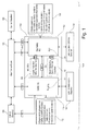
- FIG. 1 an example block diagram of Instrumentation and Control (I&C) system 100 (hereinafter referred to as 'I&C system 100') for an Emergency Diesel Generator (EDG) 1000 of the nuclear power plants is illustrated in accordance with an exemplary embodiment of the present disclosure.
- I&C Instrumentation and Control
- EDG Emergency Diesel Generator
- the I&C system 100 is adapted to be divided into parts, i.e., a first control part 110 and a second control part 120.
- the first control part 110 includes Safety I&C functions, as depicted in block 112, adapted to be controlled by wired logics based on electromechanical relays 114.
- the second control part 120 includes Non-safety I&C functions, as depicted in block 122, adapted to be controlled by Programmable Logic Controllers (PLCs)/ Human Machine Interface (HMI) 124.
- PLCs Programmable Logic Controllers
- HMI Human Machine Interface
- the Safety I&C functions may be related to availability and efficiency of EDG, which may at least be one of an Engine Emergency Starting/Stopping system and supervision, a Speed Control Unit, an Excitations and Regulation Unit, Fuel Oil System, Lube Oil System, and Preheating and Cooling Water System, and Generator supervision safety and safety auxiliary functions etc.
- Non-safety I&C functions may related to indications, measuring and monitoring systems of EDG, which may at least be one of Alarm and signalization Systems, Physical Measurement Systems, Non-Safety Electrical Protections, and Synchronization, etc.
- the Safety and Non-safety functions may be configured to include respective interface functions thereof, wherein the interface functions include respective input and outputs signals of each Safety and Non-safety functions.
- I&C system may further include a protection means, 130 to protect data exchanges between the first control part incorporating Safety I&C functions and second control part incorporating Non-safety I&C functions.
- the protection means may be based on physical separation, such as specific gap 130, between classified circuits of the Safety and Non-safety I&C functions of the in the first and second control parts 110, 120.
- the protection means may be based on electrical insulation (not shown) between the Safety and Non-safety I&C functions in the first and second control parts 110, 120.
- the I&C system 100 is adapted to be communicably configured to various other units.
- the first and second control parts 110, 120 relating to the Safety and Non-safety I&C functions are adapted and configured to communicate with a main control room 150, which is also in communication with various other non-classified units 152, 154.
- the second control part 120 may for example communicates with a non-classified Digital Protection EDG 160, a non-classified Digital Measuring Device EDG 162, and non-classified Instrumentation EDG 164.
- the first control part 110 may for example communicates with non-classified Instrumentation EDG 166 and other non-classified unit 154.
- FIG. 1 is only an example block illustration of the I&C system 100, and the scope of the present disclosure should not considered limiting in any sense to FIG. 1 , which may include various modifications, arrangement or rearrangement as per the industry need and requirement.
- the system 100 of the present disclosure is advantageous in various scopes such as described above. Further, the system is advantageous in incorporating analog technologies, such as electromechanical relays, as well as digital technologies, such as Programmable Logic Controllers (PLCs) based on the classification of Safety and Non-safety functions of the nuclear I&C system.
- PLCs Programmable Logic Controllers
Abstract
Description
- The present invention generally relates to nuclear power plants, and more particularly to a nuclear Instrumentation and Control (I&C) system incorporated in the Emergency Diesel Generator (EDG) of the Nuclear Power Plants.
- Emergency Diesel Generators (EDGs) are essential part of the nuclear power plants, whose function is to provide emergency electrical power to critical equipment of the nuclear power plants in case of onsite, offsite events and/or incase when the power source becomes unavailable or degraded.
- Generally, EDGs are located in a dedicated area of the nuclear power plant, and includes, along with various other components, an Instrumentation and Control (I&C) system incorporated therein. The I&C systems, such as, speed regulation, synchronous, relaying, Programmable Logical Controller (PLC)/Human machine Interface (HMI), polarity distributions, are important electrical auxiliaries of the EDGs in regard to the efficient operation of the EDGs.
- Most of the present I&C systems in the nuclear power plants are based on analog technologies including analog electronic modules, electromagnetic relays etc. These analog technologies are quite a mature and compliant with severe requirements of safety applications in nuclear power plants. However, as such analog technologies based I&C systems become older, they may experience a higher failure rate with associated increased maintenance costs. The primary concern with the extended use of analog systems is effects of aging such as mechanical failures, environmental degradation, and obsolescence.
- The technical solutions currently available on the market mainly count on digital technologies such as microprocessors, hardware, and software, PLC. Such digital technologies are essentially free of the drift that afflicts analog electronics, so the scale can be maintained better. However, these digital technologies are relatively new for I&C systems and are raising many technical and procedural issues, such as, the quantification of software reliability fault tolerance, self-testing, signal verification and validation, process system diagnostics etc.
- Accordingly, there exists a need for entirely new approaches to achieve the required reliability, and, have a robust and flexible I&C system in terms of maintenance, reliability compactness in economical and effective manner.
- The present disclosure discloses a nuclear Instrumentation and Control (I&C) system for an Emergency Diesel Generator (EDG) in the nuclear power plants that will be presented in the following simplified summary to provide a basic understanding of one or more aspects of the disclosure that are intended to overcome the discussed drawbacks, but to include all advantages thereof, along with providing some additional advantages. This summary is not an extensive overview of the disclosure. It is intended to neither identify key or critical elements of the disclosure, nor to delineate the scope of the present disclosure. Rather, the sole purpose of this summary is to present some concepts of the disclosure, its aspects and advantages in a simplified form as a prelude to the more detailed description that is presented hereinafter.
- A general object of the present disclosure is to describe a nuclear I&C system that may be robust and flexible in terms of maintenance and reliability compactness. Further object of the present disclosure is to describe a nuclear I&C system that may incorporate analog technologies, such as electromechanical relays, as well as digital technologies, such as Programmable Logic Controllers (PLCs) based on the classification of Safety and Non-safety functions of the nuclear I&C system.
- In one aspect of the present disclosure, an Instrumentation and Control (I&C) system for Emergency Diesel Generator (EDG) of the nuclear power plants is provided. The I&C system is adapted to be divided into parts, i.e., a first control part and a second control part. The first control part includes Safety I&C functions adapted to be controlled by wired logics based on electromechanical relays. Further, the second control part includes Non-safety I&C functions adapted to be controlled by Programmable Logic Controllers (PLCs)/ Human Machine Interface (HMI).
- In accordance with an embodiment, the Safety I&C functions may be related to availability and efficiency of EDG, which may at least be one of an Emergency Starting/Stopping EDG, a Speed Control Unit, Excitations and Regulation Unit, Fuel Oil System, Lube Oil System, and Preheating and Cooling Water System. Further the Non-safety I&C functions may be related to indications, measuring and monitoring systems of EDG, which may at least be one of Alarm Systems, Physical Measurement Systems, Non-Safety Electrical Protections, and Synchronization.
- In accordance with an embodiment, the Safety and Non-safety functions may be configured to include respective interface functions thereof, wherein the interface functions include respective input and outputs signals of the Safety and Non-safety functions.
- In accordance with an embodiment, I&C system may further include a protection means to protect data exchanges between the first control part incorporating Safety I&C functions and second control part incorporating Non-safety I&C functions. In an embodiment, the protection means may be based on physical separation between classified circuits of the Safety and Non-safety I&C functions in the first and second control parts. In further embodiment, the protection means may be based on electrical insulation between the Safety and Non-safety I&C functions in the first and second control parts.
- These together with the other aspects of the present disclosure, along with the various features of novelty that characterize the present disclosure, are pointed out with particularity in the present disclosure. For a better understanding of the present disclosure, its operating advantages, and its uses, reference should be made to the accompanying drawings and descriptive matter in which there are illustrated exemplary embodiments of the present disclosure.
- The advantages and features of the present disclosure will better understood with reference to the following detailed description and claims taken in conjunction with the accompanying drawing, wherein like elements are identified with like symbols, and in which:
-
FIG. 1 illustrates a block diagram of Instrumentation and Control (I&C) system for Emergency Diesel Generator (EDG) of the nuclear power plants, in accordance with an exemplary embodiment of the present disclosure. - Like reference numerals refer to like parts throughout the description of several views of the drawings.
- For a thorough understanding of the present disclosure, reference is to be made to the following detailed description, including the appended claims, in connection with the above-described drawings. In the following description, for purposes of explanation, numerous specific details are set forth in order to provide a thorough understanding of the present disclosure. It will be apparent, however, to one skilled in the art that the present disclosure can be practiced without these specific details. In other instances, structures and devices are shown in block diagrams form only, in order to avoid obscuring the disclosure. Reference in this specification to "one embodiment," "an embodiment," "another embodiment," "various embodiments," means that a particular feature, structure, or characteristic described in connection with the embodiment is included in at least one embodiment of the present disclosure. The appearance of the phrase "in one embodiment" in various places in the specification are not necessarily all referring to the same embodiment, nor are separate or alternative embodiments mutually exclusive of other embodiments. Moreover, various features are described which may be exhibited by some embodiments and not by others. Similarly, various requirements are described which may be requirements for some embodiments but may not be of other embodiment's requirement.
- Although the following description contains many specifics for the purposes of illustration, anyone skilled in the art will appreciate that many variations and/or alterations to these details are within the scope of the present disclosure. Similarly, although many of the features of the present disclosure are described in terms of each other, or in conjunction with each other, one skilled in the art will appreciate that many of these features can be provided independently of other features. Accordingly, this description of the present disclosure is set forth without any loss of generality to, and without imposing limitations upon, the present disclosure. Further, the relative terms used herein do not denote any order, elevation or importance, but rather are used to distinguish one element from another. Further, the terms "a," "an," and "plurality" herein do not denote a limitation of quantity, but rather denote the presence of at least one of the referenced item.
- Referring to
FIG. 1 , an example block diagram of Instrumentation and Control (I&C) system 100 (hereinafter referred to as 'I&C system 100') for an Emergency Diesel Generator (EDG) 1000 of the nuclear power plants is illustrated in accordance with an exemplary embodiment of the present disclosure. In as much as the construction and arrangement of the I&Csystem 100, various associated elements may be well-known to those skilled in the art, it is not deemed necessary for purposes of acquiring an understanding of the present disclosure that there be recited herein all of the constructional details and explanation thereof. Rather, it is deemed sufficient to simply note that as shown inFIG. 1 , in theI&C system 100, only those components are shown that are relevant for the description of various embodiments of the present disclosure. - As shown in
FIG. 1 , theI&C system 100 is adapted to be divided into parts, i.e., afirst control part 110 and asecond control part 120. Thefirst control part 110 includes Safety I&C functions, as depicted inblock 112, adapted to be controlled by wired logics based onelectromechanical relays 114. Further, thesecond control part 120 includes Non-safety I&C functions, as depicted inblock 122, adapted to be controlled by Programmable Logic Controllers (PLCs)/ Human Machine Interface (HMI) 124. - In accordance with an embodiment, as depicted in the
block 112, the Safety I&C functions may be related to availability and efficiency of EDG, which may at least be one of an Engine Emergency Starting/Stopping system and supervision, a Speed Control Unit, an Excitations and Regulation Unit, Fuel Oil System, Lube Oil System, and Preheating and Cooling Water System, and Generator supervision safety and safety auxiliary functions etc. - Further the Non-safety I&C functions, as depicted in the
block 122, may related to indications, measuring and monitoring systems of EDG, which may at least be one of Alarm and signalization Systems, Physical Measurement Systems, Non-Safety Electrical Protections, and Synchronization, etc. - In accordance with an embodiment, the Safety and Non-safety functions may be configured to include respective interface functions thereof, wherein the interface functions include respective input and outputs signals of each Safety and Non-safety functions.
- In accordance with an embodiment, I&C system may further include a protection means, 130 to protect data exchanges between the first control part incorporating Safety I&C functions and second control part incorporating Non-safety I&C functions. In an embodiment, the protection means may be based on physical separation, such as
specific gap 130, between classified circuits of the Safety and Non-safety I&C functions of the in the first andsecond control parts second control parts - The I&C
system 100 is adapted to be communicably configured to various other units. For example, the first andsecond control parts main control room 150, which is also in communication with various other non-classifiedunits second control part 120 may for example communicates with a non-classifiedDigital Protection EDG 160, a non-classified DigitalMeasuring Device EDG 162, andnon-classified Instrumentation EDG 164. Similarly, thefirst control part 110 may for example communicates withnon-classified Instrumentation EDG 166 and othernon-classified unit 154.FIG. 1 is only an example block illustration of theI&C system 100, and the scope of the present disclosure should not considered limiting in any sense toFIG. 1 , which may include various modifications, arrangement or rearrangement as per the industry need and requirement. - The
system 100 of the present disclosure is advantageous in various scopes such as described above. Further, the system is advantageous in incorporating analog technologies, such as electromechanical relays, as well as digital technologies, such as Programmable Logic Controllers (PLCs) based on the classification of Safety and Non-safety functions of the nuclear I&C system. The system economically and effectively provides robustness and flexibility in terms of maintenance and reliability compactness. - The foregoing descriptions of specific embodiments of the present disclosure have been presented for purposes of illustration and description. They are not intended to be exhaustive or to limit the present disclosure to the precise forms disclosed, and obviously many modifications and variations are possible in light of the above teaching. The embodiments were chosen and described in order to best explain the principles of the present disclosure and its practical application, to thereby enable others skilled in the art to best utilize the present disclosure and various embodiments with various modifications as are suited to the particular use contemplated. It is understood that various omission and substitutions of equivalents are contemplated as circumstance may suggest or render expedient, but such are intended to cover the application or implementation without departing from the spirit or scope of the claims of the present disclosure.
-
- 1000
- Emergency Diesel Generator (EDG)
- 100
- Instrumentation and Control system; I&C system
- 110
- First control part
- 112
- Block depicting Safety I&C functions
- 114
- Electromechanical relays
- 120
- Second control part
- 122
- Block depicting Non-safety I&C functions
- 124
- Programmable Logic Controllers (PLCs)/ Human Machine Interface (HMI)
- 130
- Protection means, separation (gap), electrical insulations
- 150
- Main control room
- 152, 154
- Non-classified units
- 160
- Non-classified
Digital Protection EDG 160 - 162
- Non-classified Digital Measuring Device EDG
- 164
- Non-classified Instrumentation EDG
- 166
- Non-classified Instrumentation EDG
Claims (7)
- An Instrumentation and Control (I&C) system for Emergency Diesel Generator (EDG) of the nuclear power plants, the instrumentation and control system, comprising:a first control part having Safety I&C functions adapted to be controlled by wired logics based on electromechanical relays; anda second control part having Non-safety I&C functions adapted to be controlled by Programmable Logic Controllers (PLCs)/ Human Machine Interface (HMI).
- The nuclear instrumentation and control system as claimed in claim 1, wherein the Safety I&C functions is related to availability and efficiency of EDG, which is at least one of an Engine Emergency Starting/Stopping system and supervision, a Speed Control Unit, Excitations and Regulation Unit, Fuel Oil System, Lube Oil System, and Preheating and Cooling Water System, Generator supervision safety and safety auxiliary functions.
- The nuclear instrumentation and control system as claimed in claim 1, wherein Non-safety I&C functions is related to indications, measuring and monitoring systems of EDG, which is at least one of Alarm and signalization Systems, Physical Measurement Systems, Non-Safety Electrical Protections, and Synchronization.
- The nuclear instrumentation and control system as claimed in claim 1, wherein the Safety and Non-safety functions are configured to include respective interface functions thereof, wherein the interface functions include respective input and outputs signals of the Safety and Non-safety functions.
- The nuclear instrumentation and control system as claimed in claim 1, further comprising a protection means to protect data exchanges between the first control part incorporating Safety I&C functions and second control part incorporating Non-safety I&C functions.
- The nuclear instrumentation and control system as claimed in claim 5, wherein the protection means is based on physical separation between classified circuits of the Safety and Non-safety I&C functions in the first and second control parts.
- The nuclear instrumentation and control system as claimed in claim 5, wherein the protection means is based on electrical insulation between the Safety and Non-safety I&C functions in the first and second control parts, wherein the electrical insulation is realized by Optocouplers, interface relays, converters, transformers, fuses and a plurality of power supplies.
Priority Applications (4)
| Application Number | Priority Date | Filing Date | Title |
|---|---|---|---|
| EP15290104.7A EP3082133B1 (en) | 2015-04-14 | 2015-04-14 | Nuclear instrumentation and control system |
| US15/097,012 US20160307655A1 (en) | 2015-04-14 | 2016-04-12 | Nuclear instrumentation and control system |
| RU2016114136A RU2716696C2 (en) | 2015-04-14 | 2016-04-13 | Control and measurement and control system for nuclear power plant |
| CN201610398513.1A CN106089460B (en) | 2015-04-14 | 2016-04-14 | Nuclear instrumentation and control system |
Applications Claiming Priority (1)
| Application Number | Priority Date | Filing Date | Title |
|---|---|---|---|
| EP15290104.7A EP3082133B1 (en) | 2015-04-14 | 2015-04-14 | Nuclear instrumentation and control system |
Publications (2)
| Publication Number | Publication Date |
|---|---|
| EP3082133A1 true EP3082133A1 (en) | 2016-10-19 |
| EP3082133B1 EP3082133B1 (en) | 2023-06-07 |
Family
ID=53717960
Family Applications (1)
| Application Number | Title | Priority Date | Filing Date |
|---|---|---|---|
| EP15290104.7A Active EP3082133B1 (en) | 2015-04-14 | 2015-04-14 | Nuclear instrumentation and control system |
Country Status (4)
| Country | Link |
|---|---|
| US (1) | US20160307655A1 (en) |
| EP (1) | EP3082133B1 (en) |
| CN (1) | CN106089460B (en) |
| RU (1) | RU2716696C2 (en) |
Families Citing this family (8)
| Publication number | Priority date | Publication date | Assignee | Title |
|---|---|---|---|---|
| EP2988420B1 (en) * | 2014-08-20 | 2021-03-10 | Framatome | Circuit arrangement for a safety i&c system |
| KR102514568B1 (en) * | 2016-12-30 | 2023-03-27 | 뉴스케일 파워, 엘엘씨 | Nuclear reactor protection systems and methods |
| CN108305695B (en) * | 2017-01-13 | 2021-02-26 | 海洋王(东莞)照明科技有限公司 | Nuclear island monitoring system |
| FR3063855B1 (en) * | 2017-03-08 | 2019-04-12 | Areva Np | PROGRAMMABLE LOGIC CIRCUIT FOR CONTROLLING AN ELECTRICAL INSTALLATION, IN PARTICULAR A NUCLEAR INSTALLATION, DEVICE AND CONTROL METHOD THEREOF |
| KR102650516B1 (en) * | 2017-06-23 | 2024-03-21 | 캔두 에너지 인코포레이티드 | Communication systems and methods for nuclear reactor tooling |
| CN111149175B (en) * | 2017-08-18 | 2023-04-07 | 西屋电气有限责任公司 | Nuclear instrument isolation output signal scaling method and system adopting same |
| CN108682467B (en) * | 2018-05-24 | 2021-05-18 | 福建福清核电有限公司 | Operation maintenance method for nuclear-grade digital instrument control system of pressurized water reactor nuclear power plant |
| CN112283002A (en) * | 2020-10-30 | 2021-01-29 | 江苏核电有限公司 | Method for evaluating starting performance of emergency diesel generator set |
Citations (4)
| Publication number | Priority date | Publication date | Assignee | Title |
|---|---|---|---|---|
| US3888772A (en) * | 1972-04-04 | 1975-06-10 | Westinghouse Electric Corp | Communication between redundant protection and safeguards logic systems within nuclear reactor power plants by means of light |
| US6292523B1 (en) * | 1997-06-06 | 2001-09-18 | Westinghouse Electric Company Llc | Digital engineered safety features actuation system |
| US6516041B1 (en) * | 1999-10-07 | 2003-02-04 | Westinghouse Electric Co. Llc | Method and apparatus to eliminate confirmation switches and channel demultiplexer from soft control man-machine interface (MMI) |
| CN103413585A (en) * | 2013-07-31 | 2013-11-27 | 中科华核电技术研究院有限公司 | Digital out-of-pile nuclear measurement system based on PC/104 bus |
Family Cites Families (4)
| Publication number | Priority date | Publication date | Assignee | Title |
|---|---|---|---|---|
| JPH01284798A (en) * | 1988-05-11 | 1989-11-16 | Toshiba Corp | Output monitor for nuclear reactor instrumentation |
| UA78477C2 (en) * | 2006-08-28 | 2007-03-15 | Yevhenii Stepanovych Bakhmach | Control digital safety system of nuclear station and method for providing the safety system parameters |
| CN103852259B (en) * | 2012-12-06 | 2017-02-22 | 中核核电运行管理有限公司 | Mechanical overspeed protective device verification system of nuclear power emergency meeting diesel engine |
| CN203769983U (en) * | 2014-01-10 | 2014-08-13 | 武汉海王新能源工程技术有限公司 | Auxiliary fuel oil system for emergency diesel oil generator set in nuclear power station |
-
2015
- 2015-04-14 EP EP15290104.7A patent/EP3082133B1/en active Active
-
2016
- 2016-04-12 US US15/097,012 patent/US20160307655A1/en not_active Abandoned
- 2016-04-13 RU RU2016114136A patent/RU2716696C2/en active
- 2016-04-14 CN CN201610398513.1A patent/CN106089460B/en active Active
Patent Citations (4)
| Publication number | Priority date | Publication date | Assignee | Title |
|---|---|---|---|---|
| US3888772A (en) * | 1972-04-04 | 1975-06-10 | Westinghouse Electric Corp | Communication between redundant protection and safeguards logic systems within nuclear reactor power plants by means of light |
| US6292523B1 (en) * | 1997-06-06 | 2001-09-18 | Westinghouse Electric Company Llc | Digital engineered safety features actuation system |
| US6516041B1 (en) * | 1999-10-07 | 2003-02-04 | Westinghouse Electric Co. Llc | Method and apparatus to eliminate confirmation switches and channel demultiplexer from soft control man-machine interface (MMI) |
| CN103413585A (en) * | 2013-07-31 | 2013-11-27 | 中科华核电技术研究院有限公司 | Digital out-of-pile nuclear measurement system based on PC/104 bus |
Also Published As
| Publication number | Publication date |
|---|---|
| RU2016114136A (en) | 2017-10-18 |
| RU2016114136A3 (en) | 2019-09-24 |
| CN106089460A (en) | 2016-11-09 |
| RU2716696C2 (en) | 2020-03-13 |
| CN106089460B (en) | 2021-05-25 |
| EP3082133B1 (en) | 2023-06-07 |
| US20160307655A1 (en) | 2016-10-20 |
Similar Documents
| Publication | Publication Date | Title |
|---|---|---|
| EP3082133A1 (en) | Nuclear instrumentation and control system | |
| EP2708964B1 (en) | Devices and methods for diagnosis of industrial electronic based products | |
| RU2376564C1 (en) | Vibration control device (versions) | |
| Abdelmoumene et al. | A review on protective relays' developments and trends | |
| CN102393625A (en) | Single-channel safety output | |
| CN105960347B (en) | Safety device for the battery contactor in electric vehicle | |
| CN105981285A (en) | Power conversion device | |
| SA516370409B1 (en) | System for operating and monitoring power cables | |
| CN106164787B (en) | Method and apparatus for safe shutdown electrical load | |
| KR20080013153A (en) | Digital security system for nuclear power plant | |
| CN104865895A (en) | Controller Having Cpu Abnormality Detection Function | |
| RU159162U1 (en) | SYSTEM OF TECHNICAL DIAGNOSTICS AND MONITORING ADK-STsB | |
| EP2840052B1 (en) | Remote monitoring system for lifts of various types | |
| RU2375692C1 (en) | Vibration control device (versions) | |
| CN102460315A (en) | Control system for controlling a process | |
| CN104810789B (en) | Electrical protective device and affiliated method for electrical equipment | |
| RU2371695C1 (en) | Vibration control system | |
| EP4101680A1 (en) | Power distribution system, control system, railway transportation system and method for operating a power distribution system | |
| CN104183037A (en) | Novel automatic security and protection system | |
| Zheng et al. | Function modelling and risk analysis of automated level crossing based on national statistical data | |
| Blecha et al. | Influence on the failure probability | |
| RU157343U1 (en) | CABINET OF LINEAR TELEMECHANICS | |
| Ahmad et al. | Modelling and Profit Evaluation of a Repairable System Working with One Operative Unit and Three Cold Standby Units | |
| Romera et al. | A retrospective view to the magnet interlock systems at CERN | |
| Macii et al. | A safety system for zero velocity detection and operator alertness monitoring in rolling stock |
Legal Events
| Date | Code | Title | Description |
|---|---|---|---|
| PUAI | Public reference made under article 153(3) epc to a published international application that has entered the european phase |
Free format text: ORIGINAL CODE: 0009012 |
|
| AK | Designated contracting states |
Kind code of ref document: A1 Designated state(s): AL AT BE BG CH CY CZ DE DK EE ES FI FR GB GR HR HU IE IS IT LI LT LU LV MC MK MT NL NO PL PT RO RS SE SI SK SM TR |
|
| AX | Request for extension of the european patent |
Extension state: BA ME |
|
| STAA | Information on the status of an ep patent application or granted ep patent |
Free format text: STATUS: REQUEST FOR EXAMINATION WAS MADE |
|
| 17P | Request for examination filed |
Effective date: 20170419 |
|
| RBV | Designated contracting states (corrected) |
Designated state(s): AL AT BE BG CH CY CZ DE DK EE ES FI FR GB GR HR HU IE IS IT LI LT LU LV MC MK MT NL NO PL PT RO RS SE SI SK SM TR |
|
| STAA | Information on the status of an ep patent application or granted ep patent |
Free format text: STATUS: EXAMINATION IS IN PROGRESS |
|
| 17Q | First examination report despatched |
Effective date: 20180207 |
|
| STAA | Information on the status of an ep patent application or granted ep patent |
Free format text: STATUS: EXAMINATION IS IN PROGRESS |
|
| STAA | Information on the status of an ep patent application or granted ep patent |
Free format text: STATUS: EXAMINATION IS IN PROGRESS |
|
| RAP3 | Party data changed (applicant data changed or rights of an application transferred) |
Owner name: GENERAL ELECTRIC TECHNOLOGY GMBH |
|
| REG | Reference to a national code |
Ref document number: 602015083825 Country of ref document: DE Ref country code: DE Ref legal event code: R079 Free format text: PREVIOUS MAIN CLASS: G21D0003000000 Ipc: G21D0003040000 |
|
| RIC1 | Information provided on ipc code assigned before grant |
Ipc: G21D 3/00 20060101ALI20221213BHEP Ipc: G21D 1/02 20060101ALI20221213BHEP Ipc: G21D 3/04 20060101AFI20221213BHEP |
|
| GRAP | Despatch of communication of intention to grant a patent |
Free format text: ORIGINAL CODE: EPIDOSNIGR1 |
|
| STAA | Information on the status of an ep patent application or granted ep patent |
Free format text: STATUS: GRANT OF PATENT IS INTENDED |
|
| INTG | Intention to grant announced |
Effective date: 20230123 |
|
| GRAS | Grant fee paid |
Free format text: ORIGINAL CODE: EPIDOSNIGR3 |
|
| GRAA | (expected) grant |
Free format text: ORIGINAL CODE: 0009210 |
|
| STAA | Information on the status of an ep patent application or granted ep patent |
Free format text: STATUS: THE PATENT HAS BEEN GRANTED |
|
| AK | Designated contracting states |
Kind code of ref document: B1 Designated state(s): AL AT BE BG CH CY CZ DE DK EE ES FI FR GB GR HR HU IE IS IT LI LT LU LV MC MK MT NL NO PL PT RO RS SE SI SK SM TR |
|
| REG | Reference to a national code |
Ref country code: GB Ref legal event code: FG4D |
|
| REG | Reference to a national code |
Ref country code: CH Ref legal event code: EP Ref country code: AT Ref legal event code: REF Ref document number: 1577437 Country of ref document: AT Kind code of ref document: T Effective date: 20230615 |
|
| REG | Reference to a national code |
Ref country code: DE Ref legal event code: R096 Ref document number: 602015083825 Country of ref document: DE |
|
| P01 | Opt-out of the competence of the unified patent court (upc) registered |
Effective date: 20230523 |
|
| REG | Reference to a national code |
Ref country code: SE Ref legal event code: TRGR |
|
| REG | Reference to a national code |
Ref country code: LT Ref legal event code: MG9D |
|
| REG | Reference to a national code |
Ref country code: NL Ref legal event code: MP Effective date: 20230607 |
|
| PG25 | Lapsed in a contracting state [announced via postgrant information from national office to epo] |
Ref country code: NO Free format text: LAPSE BECAUSE OF FAILURE TO SUBMIT A TRANSLATION OF THE DESCRIPTION OR TO PAY THE FEE WITHIN THE PRESCRIBED TIME-LIMIT Effective date: 20230907 Ref country code: ES Free format text: LAPSE BECAUSE OF FAILURE TO SUBMIT A TRANSLATION OF THE DESCRIPTION OR TO PAY THE FEE WITHIN THE PRESCRIBED TIME-LIMIT Effective date: 20230607 |
|
| REG | Reference to a national code |
Ref country code: AT Ref legal event code: MK05 Ref document number: 1577437 Country of ref document: AT Kind code of ref document: T Effective date: 20230607 |
|
| PG25 | Lapsed in a contracting state [announced via postgrant information from national office to epo] |
Ref country code: RS Free format text: LAPSE BECAUSE OF FAILURE TO SUBMIT A TRANSLATION OF THE DESCRIPTION OR TO PAY THE FEE WITHIN THE PRESCRIBED TIME-LIMIT Effective date: 20230607 Ref country code: NL Free format text: LAPSE BECAUSE OF FAILURE TO SUBMIT A TRANSLATION OF THE DESCRIPTION OR TO PAY THE FEE WITHIN THE PRESCRIBED TIME-LIMIT Effective date: 20230607 Ref country code: LV Free format text: LAPSE BECAUSE OF FAILURE TO SUBMIT A TRANSLATION OF THE DESCRIPTION OR TO PAY THE FEE WITHIN THE PRESCRIBED TIME-LIMIT Effective date: 20230607 Ref country code: LT Free format text: LAPSE BECAUSE OF FAILURE TO SUBMIT A TRANSLATION OF THE DESCRIPTION OR TO PAY THE FEE WITHIN THE PRESCRIBED TIME-LIMIT Effective date: 20230607 Ref country code: HR Free format text: LAPSE BECAUSE OF FAILURE TO SUBMIT A TRANSLATION OF THE DESCRIPTION OR TO PAY THE FEE WITHIN THE PRESCRIBED TIME-LIMIT Effective date: 20230607 Ref country code: GR Free format text: LAPSE BECAUSE OF FAILURE TO SUBMIT A TRANSLATION OF THE DESCRIPTION OR TO PAY THE FEE WITHIN THE PRESCRIBED TIME-LIMIT Effective date: 20230908 |
|
| PG25 | Lapsed in a contracting state [announced via postgrant information from national office to epo] |
Ref country code: FI Free format text: LAPSE BECAUSE OF FAILURE TO SUBMIT A TRANSLATION OF THE DESCRIPTION OR TO PAY THE FEE WITHIN THE PRESCRIBED TIME-LIMIT Effective date: 20230607 |
|
| PG25 | Lapsed in a contracting state [announced via postgrant information from national office to epo] |
Ref country code: SK Free format text: LAPSE BECAUSE OF FAILURE TO SUBMIT A TRANSLATION OF THE DESCRIPTION OR TO PAY THE FEE WITHIN THE PRESCRIBED TIME-LIMIT Effective date: 20230607 |
|
| PG25 | Lapsed in a contracting state [announced via postgrant information from national office to epo] |
Ref country code: IS Free format text: LAPSE BECAUSE OF FAILURE TO SUBMIT A TRANSLATION OF THE DESCRIPTION OR TO PAY THE FEE WITHIN THE PRESCRIBED TIME-LIMIT Effective date: 20231007 |
|
| PG25 | Lapsed in a contracting state [announced via postgrant information from national office to epo] |
Ref country code: SM Free format text: LAPSE BECAUSE OF FAILURE TO SUBMIT A TRANSLATION OF THE DESCRIPTION OR TO PAY THE FEE WITHIN THE PRESCRIBED TIME-LIMIT Effective date: 20230607 Ref country code: SK Free format text: LAPSE BECAUSE OF FAILURE TO SUBMIT A TRANSLATION OF THE DESCRIPTION OR TO PAY THE FEE WITHIN THE PRESCRIBED TIME-LIMIT Effective date: 20230607 Ref country code: PT Free format text: LAPSE BECAUSE OF FAILURE TO SUBMIT A TRANSLATION OF THE DESCRIPTION OR TO PAY THE FEE WITHIN THE PRESCRIBED TIME-LIMIT Effective date: 20231009 Ref country code: IS Free format text: LAPSE BECAUSE OF FAILURE TO SUBMIT A TRANSLATION OF THE DESCRIPTION OR TO PAY THE FEE WITHIN THE PRESCRIBED TIME-LIMIT Effective date: 20231007 Ref country code: EE Free format text: LAPSE BECAUSE OF FAILURE TO SUBMIT A TRANSLATION OF THE DESCRIPTION OR TO PAY THE FEE WITHIN THE PRESCRIBED TIME-LIMIT Effective date: 20230607 Ref country code: CZ Free format text: LAPSE BECAUSE OF FAILURE TO SUBMIT A TRANSLATION OF THE DESCRIPTION OR TO PAY THE FEE WITHIN THE PRESCRIBED TIME-LIMIT Effective date: 20230607 Ref country code: AT Free format text: LAPSE BECAUSE OF FAILURE TO SUBMIT A TRANSLATION OF THE DESCRIPTION OR TO PAY THE FEE WITHIN THE PRESCRIBED TIME-LIMIT Effective date: 20230607 |
|
| PG25 | Lapsed in a contracting state [announced via postgrant information from national office to epo] |
Ref country code: PL Free format text: LAPSE BECAUSE OF FAILURE TO SUBMIT A TRANSLATION OF THE DESCRIPTION OR TO PAY THE FEE WITHIN THE PRESCRIBED TIME-LIMIT Effective date: 20230607 |