EP3093067A1 - Device and method for mixing and storing of polymethylmethacrylate bone cement - Google Patents
Device and method for mixing and storing of polymethylmethacrylate bone cement Download PDFInfo
- Publication number
- EP3093067A1 EP3093067A1 EP15180189.1A EP15180189A EP3093067A1 EP 3093067 A1 EP3093067 A1 EP 3093067A1 EP 15180189 A EP15180189 A EP 15180189A EP 3093067 A1 EP3093067 A1 EP 3093067A1
- Authority
- EP
- European Patent Office
- Prior art keywords
- hollow cylinder
- monomer
- cartridge
- interior
- pump piston
- Prior art date
- Legal status (The legal status is an assumption and is not a legal conclusion. Google has not performed a legal analysis and makes no representation as to the accuracy of the status listed.)
- Granted
Links
- 239000002639 bone cement Substances 0.000 title claims abstract description 62
- 229920003229 poly(methyl methacrylate) Polymers 0.000 title claims abstract description 30
- 239000004926 polymethyl methacrylate Substances 0.000 title claims abstract description 30
- 238000000034 method Methods 0.000 title claims abstract description 22
- 239000000178 monomer Substances 0.000 claims abstract description 279
- 239000007788 liquid Substances 0.000 claims abstract description 146
- 239000000843 powder Substances 0.000 claims abstract description 85
- 239000004568 cement Substances 0.000 claims abstract description 83
- 239000012530 fluid Substances 0.000 claims abstract description 8
- 230000006835 compression Effects 0.000 claims description 10
- 238000007906 compression Methods 0.000 claims description 10
- 239000011148 porous material Substances 0.000 claims description 7
- 239000012634 fragment Substances 0.000 claims description 6
- NJPPVKZQTLUDBO-UHFFFAOYSA-N novaluron Chemical compound C1=C(Cl)C(OC(F)(F)C(OC(F)(F)F)F)=CC=C1NC(=O)NC(=O)C1=C(F)C=CC=C1F NJPPVKZQTLUDBO-UHFFFAOYSA-N 0.000 claims description 5
- 230000000717 retained effect Effects 0.000 claims description 4
- 230000001960 triggered effect Effects 0.000 claims description 2
- 150000001875 compounds Chemical class 0.000 claims 1
- 239000003708 ampul Substances 0.000 description 13
- 229920003023 plastic Polymers 0.000 description 11
- 239000004033 plastic Substances 0.000 description 11
- 238000012546 transfer Methods 0.000 description 10
- 239000011521 glass Substances 0.000 description 7
- 239000002245 particle Substances 0.000 description 7
- 239000006072 paste Substances 0.000 description 7
- VVQNEPGJFQJSBK-UHFFFAOYSA-N Methyl methacrylate Chemical compound COC(=O)C(C)=C VVQNEPGJFQJSBK-UHFFFAOYSA-N 0.000 description 6
- 230000001954 sterilising effect Effects 0.000 description 6
- 239000000203 mixture Substances 0.000 description 5
- 238000010526 radical polymerization reaction Methods 0.000 description 5
- 238000007789 sealing Methods 0.000 description 5
- 238000004659 sterilization and disinfection Methods 0.000 description 5
- 230000009471 action Effects 0.000 description 4
- 230000005484 gravity Effects 0.000 description 4
- 238000001746 injection moulding Methods 0.000 description 4
- 229920000642 polymer Polymers 0.000 description 4
- 239000012966 redox initiator Substances 0.000 description 4
- 230000008961 swelling Effects 0.000 description 4
- 230000008719 thickening Effects 0.000 description 4
- IAYPIBMASNFSPL-UHFFFAOYSA-N Ethylene oxide Chemical compound C1CO1 IAYPIBMASNFSPL-UHFFFAOYSA-N 0.000 description 3
- 238000003825 pressing Methods 0.000 description 3
- 238000005086 pumping Methods 0.000 description 3
- 238000003860 storage Methods 0.000 description 3
- OMPJBNCRMGITSC-UHFFFAOYSA-N Benzoylperoxide Chemical compound C=1C=CC=CC=1C(=O)OOC(=O)C1=CC=CC=C1 OMPJBNCRMGITSC-UHFFFAOYSA-N 0.000 description 2
- BAPJBEWLBFYGME-UHFFFAOYSA-N Methyl acrylate Chemical compound COC(=O)C=C BAPJBEWLBFYGME-UHFFFAOYSA-N 0.000 description 2
- PPBRXRYQALVLMV-UHFFFAOYSA-N Styrene Chemical compound C=CC1=CC=CC=C1 PPBRXRYQALVLMV-UHFFFAOYSA-N 0.000 description 2
- 239000012190 activator Substances 0.000 description 2
- 238000005452 bending Methods 0.000 description 2
- 230000008901 benefit Effects 0.000 description 2
- 235000019400 benzoyl peroxide Nutrition 0.000 description 2
- 230000015572 biosynthetic process Effects 0.000 description 2
- 238000011161 development Methods 0.000 description 2
- 230000018109 developmental process Effects 0.000 description 2
- 230000005611 electricity Effects 0.000 description 2
- GYVGXEWAOAAJEU-UHFFFAOYSA-N n,n,4-trimethylaniline Chemical compound CN(C)C1=CC=C(C)C=C1 GYVGXEWAOAAJEU-UHFFFAOYSA-N 0.000 description 2
- 230000035515 penetration Effects 0.000 description 2
- 238000006116 polymerization reaction Methods 0.000 description 2
- 230000002028 premature Effects 0.000 description 2
- 238000010008 shearing Methods 0.000 description 2
- 230000002411 adverse Effects 0.000 description 1
- 238000013459 approach Methods 0.000 description 1
- 230000004888 barrier function Effects 0.000 description 1
- 230000000903 blocking effect Effects 0.000 description 1
- 210000000988 bone and bone Anatomy 0.000 description 1
- 239000003638 chemical reducing agent Substances 0.000 description 1
- 238000010276 construction Methods 0.000 description 1
- 238000005520 cutting process Methods 0.000 description 1
- 230000001687 destabilization Effects 0.000 description 1
- 210000000501 femur body Anatomy 0.000 description 1
- 230000012447 hatching Effects 0.000 description 1
- 239000003999 initiator Substances 0.000 description 1
- 238000009434 installation Methods 0.000 description 1
- 230000000670 limiting effect Effects 0.000 description 1
- 230000007774 longterm Effects 0.000 description 1
- 238000004519 manufacturing process Methods 0.000 description 1
- 238000013508 migration Methods 0.000 description 1
- 230000005012 migration Effects 0.000 description 1
- 230000036961 partial effect Effects 0.000 description 1
- 230000000149 penetrating effect Effects 0.000 description 1
- 150000002978 peroxides Chemical class 0.000 description 1
- 238000012545 processing Methods 0.000 description 1
- 230000002441 reversible effect Effects 0.000 description 1
- 239000002689 soil Substances 0.000 description 1
- 238000010557 suspension polymerization reaction Methods 0.000 description 1
- 230000002123 temporal effect Effects 0.000 description 1
- 239000012780 transparent material Substances 0.000 description 1
Images


Classifications
-
- B—PERFORMING OPERATIONS; TRANSPORTING
- B01—PHYSICAL OR CHEMICAL PROCESSES OR APPARATUS IN GENERAL
- B01F—MIXING, e.g. DISSOLVING, EMULSIFYING OR DISPERSING
- B01F31/00—Mixers with shaking, oscillating, or vibrating mechanisms
- B01F31/40—Mixers with shaking, oscillating, or vibrating mechanisms with an axially oscillating rotary stirrer
-
- B—PERFORMING OPERATIONS; TRANSPORTING
- B29—WORKING OF PLASTICS; WORKING OF SUBSTANCES IN A PLASTIC STATE IN GENERAL
- B29B—PREPARATION OR PRETREATMENT OF THE MATERIAL TO BE SHAPED; MAKING GRANULES OR PREFORMS; RECOVERY OF PLASTICS OR OTHER CONSTITUENTS OF WASTE MATERIAL CONTAINING PLASTICS
- B29B7/00—Mixing; Kneading
- B29B7/74—Mixing; Kneading using other mixers or combinations of mixers, e.g. of dissimilar mixers ; Plant
-
- A—HUMAN NECESSITIES
- A61—MEDICAL OR VETERINARY SCIENCE; HYGIENE
- A61B—DIAGNOSIS; SURGERY; IDENTIFICATION
- A61B17/00—Surgical instruments, devices or methods, e.g. tourniquets
- A61B17/56—Surgical instruments or methods for treatment of bones or joints; Devices specially adapted therefor
- A61B17/58—Surgical instruments or methods for treatment of bones or joints; Devices specially adapted therefor for osteosynthesis, e.g. bone plates, screws, setting implements or the like
- A61B17/88—Osteosynthesis instruments; Methods or means for implanting or extracting internal or external fixation devices
- A61B17/8802—Equipment for handling bone cement or other fluid fillers
- A61B17/8833—Osteosynthesis tools specially adapted for handling bone cement or fluid fillers; Means for supplying bone cement or fluid fillers to introducing tools, e.g. cartridge handling means
-
- B—PERFORMING OPERATIONS; TRANSPORTING
- B01—PHYSICAL OR CHEMICAL PROCESSES OR APPARATUS IN GENERAL
- B01F—MIXING, e.g. DISSOLVING, EMULSIFYING OR DISPERSING
- B01F33/00—Other mixers; Mixing plants; Combinations of mixers
- B01F33/50—Movable or transportable mixing devices or plants
- B01F33/501—Movable mixing devices, i.e. readily shifted or displaced from one place to another, e.g. portable during use
- B01F33/5011—Movable mixing devices, i.e. readily shifted or displaced from one place to another, e.g. portable during use portable during use, e.g. hand-held
- B01F33/50112—Movable mixing devices, i.e. readily shifted or displaced from one place to another, e.g. portable during use portable during use, e.g. hand-held of the syringe or cartridge type
-
- B—PERFORMING OPERATIONS; TRANSPORTING
- B01—PHYSICAL OR CHEMICAL PROCESSES OR APPARATUS IN GENERAL
- B01F—MIXING, e.g. DISSOLVING, EMULSIFYING OR DISPERSING
- B01F33/00—Other mixers; Mixing plants; Combinations of mixers
- B01F33/50—Movable or transportable mixing devices or plants
- B01F33/501—Movable mixing devices, i.e. readily shifted or displaced from one place to another, e.g. portable during use
- B01F33/5012—Movable mixing devices, i.e. readily shifted or displaced from one place to another, e.g. portable during use adapted to be mounted during use on a standard, base or support
-
- B—PERFORMING OPERATIONS; TRANSPORTING
- B01—PHYSICAL OR CHEMICAL PROCESSES OR APPARATUS IN GENERAL
- B01F—MIXING, e.g. DISSOLVING, EMULSIFYING OR DISPERSING
- B01F33/00—Other mixers; Mixing plants; Combinations of mixers
- B01F33/70—Mixers specially adapted for working at sub- or super-atmospheric pressure, e.g. combined with de-foaming
-
- B—PERFORMING OPERATIONS; TRANSPORTING
- B01—PHYSICAL OR CHEMICAL PROCESSES OR APPARATUS IN GENERAL
- B01F—MIXING, e.g. DISSOLVING, EMULSIFYING OR DISPERSING
- B01F35/00—Accessories for mixers; Auxiliary operations or auxiliary devices; Parts or details of general application
- B01F35/71—Feed mechanisms
- B01F35/713—Feed mechanisms comprising breaking packages or parts thereof, e.g. piercing or opening sealing elements between compartments or cartridges
- B01F35/7131—Breaking or perforating packages, containers or vials
-
- B—PERFORMING OPERATIONS; TRANSPORTING
- B01—PHYSICAL OR CHEMICAL PROCESSES OR APPARATUS IN GENERAL
- B01F—MIXING, e.g. DISSOLVING, EMULSIFYING OR DISPERSING
- B01F35/00—Accessories for mixers; Auxiliary operations or auxiliary devices; Parts or details of general application
- B01F35/71—Feed mechanisms
- B01F35/717—Feed mechanisms characterised by the means for feeding the components to the mixer
- B01F35/7174—Feed mechanisms characterised by the means for feeding the components to the mixer using pistons, plungers or syringes
-
- B—PERFORMING OPERATIONS; TRANSPORTING
- B01—PHYSICAL OR CHEMICAL PROCESSES OR APPARATUS IN GENERAL
- B01F—MIXING, e.g. DISSOLVING, EMULSIFYING OR DISPERSING
- B01F35/00—Accessories for mixers; Auxiliary operations or auxiliary devices; Parts or details of general application
- B01F35/75—Discharge mechanisms
- B01F35/754—Discharge mechanisms characterised by the means for discharging the components from the mixer
- B01F35/75425—Discharge mechanisms characterised by the means for discharging the components from the mixer using pistons or plungers
- B01F35/754251—Discharge mechanisms characterised by the means for discharging the components from the mixer using pistons or plungers reciprocating in the mixing receptacle
-
- A—HUMAN NECESSITIES
- A61—MEDICAL OR VETERINARY SCIENCE; HYGIENE
- A61B—DIAGNOSIS; SURGERY; IDENTIFICATION
- A61B17/00—Surgical instruments, devices or methods, e.g. tourniquets
- A61B17/56—Surgical instruments or methods for treatment of bones or joints; Devices specially adapted therefor
- A61B17/58—Surgical instruments or methods for treatment of bones or joints; Devices specially adapted therefor for osteosynthesis, e.g. bone plates, screws, setting implements or the like
- A61B17/88—Osteosynthesis instruments; Methods or means for implanting or extracting internal or external fixation devices
- A61B17/8802—Equipment for handling bone cement or other fluid fillers
- A61B17/8833—Osteosynthesis tools specially adapted for handling bone cement or fluid fillers; Means for supplying bone cement or fluid fillers to introducing tools, e.g. cartridge handling means
- A61B2017/8838—Osteosynthesis tools specially adapted for handling bone cement or fluid fillers; Means for supplying bone cement or fluid fillers to introducing tools, e.g. cartridge handling means for mixing bone cement or fluid fillers
-
- B—PERFORMING OPERATIONS; TRANSPORTING
- B01—PHYSICAL OR CHEMICAL PROCESSES OR APPARATUS IN GENERAL
- B01F—MIXING, e.g. DISSOLVING, EMULSIFYING OR DISPERSING
- B01F2101/00—Mixing characterised by the nature of the mixed materials or by the application field
- B01F2101/20—Mixing of ingredients for bone cement
Abstract
Die Erfindung betrifft eine Vorrichtung zum Mischen von Polymethylmethacrylat-Knochenzement und zum Lagern der Ausgangskomponenten des Knochenzements, insbesondere einer Momonerflüssigkeit und eines Zementpulvers als Ausgangskomponenten des Knochenzements, die Vorrichtung aufweisend eine Kartusche (1) mit einem Innenraum (24) zum Mischen des Knochenzements, der auf einer Seite durch einen beweglichen Austragskolben (2) verschlossen ist, einen Monomer-Behälter (46) für eine Monomerflüssigkeit und/oder einen Anschluss (20) zur Befestigung eines Monomer-Behälters (46) für eine Monomerflüssigkeit, so dass der Monomer-Behälter (46) in der Vorrichtung derart zu öffnen ist, dass die Monomerflüssigkeit aus dem Monomer-Behälter (46) in die Vorrichtung ausläuft, eine Verbindungsleitung (38), durch die die Monomerflüssigkeit in den Innenraum (24) der Kartusche (1) zu leiten ist, wobei ein Hohlzylinder (12) mit der Verbindungsleitung (38) verbunden ist und der Hohlzylinder (12) zwischen dem Monomer-Behälter (46) oder dem Anschluss für den Monomer-Behälter (46) und dem Innenraum (24) der Kartusche (1) angeordnet ist, wobei in dem Hohlzylinder (12) ein axial im Hohlzylinder (12) verschiebbarer Pumpkolben (14) angeordnet ist, wobei die Monomerflüssigkeit aus dem geöffneten Monomer-Behälter (46) in den Hohlzylinder (12) fließen kann und die Verbindungsleitung (38, 88) den Hohlzylinder (12) mit dem Innenraum (24) der Kartusche (1) derart verbindet, dass mit dem Pumpkolben (14) Monomerflüssigkeit aus dem Hohlzylinder (12) durch Betätigen des Pumpkolbens (14, 64) durch die Verbindungsleitung (38) in den Innenraum (24) der Kartusche (1) zu drücken ist. Die Erfindung betrifft auch ein Verfahren zur Vermischung von Polymethylmethacrylat-Knochenzement.The invention relates to a device for mixing polymethylmethacrylate bone cement and for storing the starting components of the bone cement, in particular a monomer fluid and a cement powder as starting components of the bone cement, comprising the device a cartridge (1) having an interior space (24) for mixing the bone cement, which is closed on one side by a movable discharge piston (2), a monomer reservoir (46) for a monomer fluid and / or a port (20) for attaching a monomer reservoir (46) for a monomer fluid such that the monomer reservoir (46) is openable in the device such that Monomer liquid from the monomer container (46) leaks into the device, a connecting line (38) through which the monomer liquid is to be led into the interior space (24) of the cartridge (1), wherein a hollow cylinder (12) is connected to the connecting line (38) and the hollow cylinder (12) is arranged between the monomer container (46) or the connection for the monomer container (46) and the inner space (24) of the cartridge (1) wherein in the hollow cylinder (12) axially displaceable in the hollow cylinder (12) pump piston (14) is arranged, wherein the monomer liquid from the opened monomer container (46) in the hollow cylinder (12) can flow and the connecting line (38, 88) connects the hollow cylinder (12) to the interior (24) of the cartridge (1) such that monomer liquid from the hollow cylinder (12) is pumped by the pump piston (14) through the connecting line (38). into the interior (24) of the cartridge (1) is to be pressed. The invention also relates to a method for mixing polymethyl methacrylate bone cement.
Description
Die Erfindung betrifft ein Mischsystem zum Mischen von Polymethylmethacrylat-Knochenzement (PMMA-Knochenzement) aus zwei Ausgangskomponenten, insbesondere zum Mischen eines medizinischen Knochenzements, und zur Lagerung der Ausgangskomponenten.The invention relates to a mixing system for mixing polymethyl methacrylate bone cement (PMMA bone cement) from two starting components, in particular for mixing a medical bone cement, and for storing the starting components.
Die Erfindung betrifft ferner ein Verfahren zum Mischen von Polymethylmethacrylat-Knochenzement.The invention further relates to a method for mixing polymethyl methacrylate bone cement.
Gegenstand der Erfindung ist somit eine Vorrichtung zur Lagerung und Vermischung von Polymethylmethacrylat-Knochenzement sowie Verfahren zum Mischen von Polymethylmethacrylat-Knochenzement.The invention thus relates to a device for storage and mixing of polymethyl methacrylate bone cement and method for mixing polymethyl methacrylate bone cement.
Polymethylmethacrylat-(PMMA)-Knochenzemente gehen auf die grundlegenden Arbeiten von Sir Charnley zurück (
Das am häufigsten in Polymethylmethacrylat-Knochenzementen verwendete Monomer ist Methylmethacrylat. Redoxinitiatorsysteme bestehen üblicherweise aus Peroxiden, Beschleunigern sowie gegebenenfalls geeigneten Reduktionsmitteln. Eine Radikalbildung erfolgt nur dann, wenn alle Bestandteile der Redoxinitiatorsysteme zusammenwirken. Deshalb werden die Bestandteile des Redoxinitiatorsystems in den separaten Ausgangskomponenten so angeordnet, dass diese keine radikalische Polymerisation auslösen können. Die Ausgangskomponenten sind bei geeigneter Zusammensetzung lagerstabil. Erst bei Vermischung der beiden Ausgangskomponenten zu einem Zementteig reagieren die zuvor getrennt in den beiden Pasten, Flüssigkeiten oder Pulvern gelagerten Bestandteile des Redoxinitiatorsystems, wobei Radikale gebildet werden, welche die radikalische Polymerisation des wenigstens einen Monomers auslösen. Die radikalische Polymerisation führt dann unter Verbrauch des Monomers zu Bildung von Polymeren, wobei der Zementteig aushärtet.The monomer most commonly used in polymethyl methacrylate bone cements is methyl methacrylate. Redox initiator systems usually consist of Peroxides, accelerators and, where appropriate, suitable reducing agents. A radical formation takes place only when all components of the redox initiator systems interact. Therefore, the components of the redox initiator system are placed in the separate starting components so that they can not initiate radical polymerization. The starting components are storage stable with a suitable composition. It is only when the two starting components are mixed to form a cement dough that the components of the redox initiator system previously stored separately in the two pastes, liquids or powders react, forming radicals which trigger the radical polymerization of the at least one monomer. The radical polymerization then leads to the formation of polymers with consumption of the monomer, wherein the cement paste hardens.
PMMA-Knochenzemente können in geeigneten Mischbechern mit Hilfe von Spateln durch Vermischen des Zementpulvers mit der Monomerflüssigkeit vermischt werden. Nachteilig ist an dieser Vorgehensweise, dass Lufteinschlüsse im gebildeten Zementteig entstehen können beziehungsweise vorhanden sein können, welche die mechanischen Eigenschaften des ausgehärteten Knochenzements negativ beeinflussen können und die somit später eine Destabilisierung des Knochenzements verursachen können.PMMA bone cements can be mixed in suitable mixing beakers by means of spatulas by mixing the cement powder with the monomer liquid. The disadvantage of this approach is that air pockets in the formed cement dough can arise or may be present, which can adversely affect the mechanical properties of the hardened bone cement and thus can later cause a destabilization of the bone cement.
Zur Vermeidung von Lufteinschlüssen im Knochenzementteig wurden eine Vielzahl von Vakuum-Zementiersystemen vorgeschlagen, von denen exemplarisch folgende genannt sind:
Eine Weiterentwicklung in der Zementiertechnik stellen Zementiersysteme dar, in denen sowohl das Zementpulver als auch die Monomerflüssigkeit bereits in separaten Kompartimenten der Mischsysteme verpackt sind und die erst unmittelbar vor der Zementapplikation im Zementiersystem miteinander vermischt werden. Solche geschlossenen Full-Prepacked-Mischsysteme wurden mit der
Das Patent
In der
Nachteilig an diesem System ist, dass Zementpulver, die schnell mit der Monomerflüssigkeit anquellen, mit dieser Vorrichtung nicht angemischt werden können, weil die schnell anquellenden Zementpulverpartikel nach einem Eindringen der Monomerflüssigkeit in das Zementpulver von ungefähr 1 bis 2 cm eine gelartige Barriere bilden und die Migration der Monomerflüssigkeit durch das gesamte Zementpulver behindern. Weiterhin kann bei Vakuumeinwirkung nicht ausgeschlossen werden, dass nach vollständiger Durchdringung des Zementpulvers durch die Monomerflüssigkeit die Monomerflüssigkeit über den Vakuumanschluss abgesaugt wird. Dann steht nicht genügend Monomerflüssigkeit für die Aushärtung durch radikalische Polymerisation zur Verfügung beziehungsweise das Mischungsverhältnis wird ungewollt verändert und damit auch die Konsistenz des Knochenzements. Weiterhin ist es problematisch, dass die zwischen den Zementpulverpartikeln eingeschlossen Luft durch die Monomerflüssigkeit von oben nach unten verdrängt werden soll, weil die gegenüber der Monomerflüssigkeit spezifisch leichtere Luft auf Grund der Schwerkraft das Bestreben hat, im Zementpulver nach oben zu wandern und nicht nach unten in Richtung Vakuumanschluss zu migrieren.A disadvantage of this system is that cement powders swelling rapidly with the monomer liquid can not be mixed with this device because the rapidly swelling cement powder particles form a gelatinous barrier after penetration of the monomer liquid into the cement powder of about 1 to 2 cm and the migration hinder the monomer liquid through the entire cement powder. Furthermore, it can not be ruled out under vacuum action that after complete penetration of the cement powder the monomer liquid is sucked off via the vacuum connection by the monomer liquid. Then there is not enough monomer liquid for curing by radical polymerization available or the mixing ratio is changed unintentionally and thus the consistency of the bone cement. Furthermore, it is problematic that the trapped between the cement powder particles air is to be displaced by the monomer liquid from top to bottom, because the lighter than the monomer liquid air due to gravity has a tendency to migrate in the cement powder upwards and not down in To migrate towards vacuum connection.
Bei der Verwendung von Vakuummischsystemen zur Zementierung müssen externe Vakuumpumpen beigestellt werden. Diese Vakuumpumpen sind kostenintensiv und müssen nach der Anwendung gereinigt werden. Weiterhin sind Vakuumschläuche zur Verbindung der Vakuumpumpen mit den Vakuummischsystemen notwendig. Diese Vakuumschläuche müssen den Vakuummischsystemen beigelegt sein. Vor dem Mischen mit einem Vakuummischsystem muss daher zuerst die Vakuumpumpe im Operations-Saal (OP-Saal) aufgebaut und an eine Energiequelle, wie Druckluft oder an elektrischen Strom angeschlossen werden. Danach wird die Vakuumpumpe mit einem Vakuumschlauch mit dem Vakuummischsystem verbunden. Diese Montageschritte kosten wertvolle OP-Zeit und sind potentiell fehlerbehaftet. Die Vakuumpumpe und die Verbindungsleitungen zum Vakuummischsystem und zu externen Energiequellen und Versorgungsleitungen benötigen Platz und stellen potentielle Stolperfallen und Hindernisse dar, die den gelegentlich hektischen Ablauf während einer Operation stören können.When using vacuum mixing systems for cementing, external vacuum pumps must be provided. These vacuum pumps are expensive and must be cleaned after use. Furthermore, vacuum hoses are necessary for connecting the vacuum pumps with the vacuum mixing systems. These vacuum hoses must be enclosed with the vacuum mixing systems. Therefore, before mixing with a vacuum mixing system, the vacuum pump must first be set up in the operating room (operating room) and connected to an energy source such as compressed air or electricity. Thereafter, the vacuum pump is connected to the vacuum mixing system with a vacuum hose. These assembly steps cost valuable operating time and are potentially flawed. The vacuum pump and the connection lines to the vacuum mixing system and to external power sources and supply lines require space and represent potential tripping hazards and obstacles that can interfere with the occasionally hectic flow during an operation.
Ein interessantes Konzept wird mit der
Die Aufgabe der Erfindung besteht also darin, die Nachteile des Stands der Technik zu überwinden. Insbesondere sollen die Nachteile der bekannten Vakuummischsysteme mit externer Vakuumquelle überwunden werden. Die Erfindung hat dabei unter anderem die Aufgabe, eine einfache, geschlossene Vorrichtung zu entwickeln, bei der Polymethylmethacrylat-Knochenzementpulver (Zementpulver) und Monomerflüssigkeit in separaten Kompartimenten gelagert und anschließend vermischt werden können. Vom medizinischen Anwender soll das Polymethylmethacrylat-Knochenzementpulver mit der Monomerflüssigkeit innerhalb der Vorrichtung zusammengeführt und vermischt werden können, ohne dass beide Zementkomponenten mit dem medizinischen Anwender in Berührung kommen. Ein Kontakt des medizinischen Anwenders mit dem Polymethylmethacrylat-Knochenzementpulver und mit der Monomerflüssigkeit soll möglichst ausgeschlossen sein. Bei der zu entwickelnden Vorrichtung handelt es sich um ein Full-Prepacked-Mischsystem. Die Vorrichtung soll so beschaffen sein, dass ein Transfer der Monomerflüssigkeit in das Polymethylmethacrylat-Knochenzementpulver ohne die Verwendung von durch Druckluft oder Kompressoren angetriebenen externen Vakuumpumpen, transferiert werden kann. Wichtig ist ferner, dass die Vorrichtung ohne externe Energiequellen, wie Druckluft, Vakuum oder elektrischer Strom, auch unter einfachsten äußeren Bedingungen funktionsfähig und zuverlässig die Herstellung von Knochenzementteig gewährleistet. Die Vorrichtung soll ohne zusätzliche technische Ausrüstung autonom verwendungsfähig sein.The object of the invention is therefore to overcome the disadvantages of the prior art. In particular, the disadvantages of the known vacuum mixing systems with external vacuum source are to be overcome. One of the objects of the invention is to develop a simple, closed device in which polymethyl methacrylate bone cement powder (cement powder) and monomer liquid can be stored in separate compartments and subsequently mixed. The medical practitioner should be able to combine and mix the polymethyl methacrylate bone cement powder with the monomer fluid within the device without the two cement components contacting the medical user. A contact of the medical user with the polymethyl methacrylate bone cement powder and with the monomer liquid should be excluded as possible. The device to be developed is a full-prepacked mixing system. The device should be such that transfer of the monomer liquid to the polymethyl methacrylate bone cement powder can be transferred without the use of external vacuum pumps driven by compressed air or compressors. It is also important that the device without external energy sources, such as compressed air, vacuum or electric current, even under the simplest external conditions functional and reliable ensures the production of bone cement dough. The device should be autonomously usable without additional technical equipment.
Weiterhin hat die Erfindung die Aufgabe, eine Vorrichtung bereit zu stellen, bei der es möglich ist, dass Volumen an Monomerflüssigkeit, die in das Zementpulver transferiert wird, gezielt zu steuern, so dass das Verhältnis des Volumens an Monomerflüssigkeit zur Zementpulvermenge variiert werden kann, um die Konsistenz und damit die Verarbeitungseigenschaften des Knochenzements zu steuern.It is another object of the present invention to provide an apparatus in which it is possible to selectively control volumes of monomer liquid transferred into the cement powder so that the ratio of the volume of monomer liquid to the amount of cement powder can be varied to control the consistency and thus the processing properties of the bone cement.
Es soll ferner ein Verfahren bereitgestellt werden, das einen Monomertransfer und ein Mischen in Full-Prepacked-Mischsystemen ermöglicht. Dabei soll das zu entwickelnde Mischsystem, hauptsächlich aus kostengünstigem Kunststoff gefertigt werden können.It is further to provide a method that allows for monomer transfer and mixing in full-prepacked mixing systems. It should be too developing mixing system, mainly made of low-cost plastic can be made.
Des Weiteren soll eine kostengünstig zu fertigende und zuverlässig funktionierende Vorrichtung zum Mischen eines medizinischen Zements und gegebenenfalls zur Lagerung der Ausgangskomponenten des Zements sowie ein Verfahren zum Mischen des Knochenzements gefunden werden, bei dem eine möglichst einfache manuelle Bedienung zum Mischen der Ausgangskomponenten angewendet werden kann, möglichst ohne dass eine externe oder zusätzliche Energiequelle verwendet werden muss und ohne dass Lufteinschlüsse in dem Mischgut entstehen.Furthermore, a cost-effective and reliably functioning device for mixing a medical cement and optionally for storing the starting components of the cement and a method for mixing the bone cement is to be found, in which the simplest possible manual operation for mixing the starting components can be used as possible without having to use an external or additional source of energy and without creating air pockets in the mix.
Die Hauptkomponente des Polymethylmethacrylat-Knochenzements als Mischgut soll ein Pulver sein und die zweite Komponente soll in Form einer Flüssigkeit vorliegen. Die beiden Ausgangskomponenten des Knochenzements sollen bevorzugt in dem Full-Prepacked-Mischsystem getrennt gelagert werden können und durch Anwendung der Vorrichtung sicher zusammengeführt werden können.The main component of the polymethyl methacrylate bone cement as a mix should be a powder and the second component should be in the form of a liquid. The two starting components of the bone cement are preferably to be stored separately in the full-prepacked mixing system and can be safely combined by using the device.
Die Aufgaben der Erfindung werden gelöst durch eine Vorrichtung zum Mischen von Polymethylmethacrylat-Knochenzement (PMMA-Knochenzement) und zum Lagern der Ausgangskomponenten des Knochenzements, insbesondere einer Momonerflüssigkeit und eines Zementpulvers als Ausgangskomponenten des Knochenzements, die Vorrichtung aufweisend
- 1) eine Kartusche mit einem Innenraum zum Mischen des Knochenzements, der auf einer Seite durch einen beweglichen Austragskolben verschlossen ist,
- 2) einen Monomer-Behälter für eine Monomerflüssigkeit und/oder einen Anschluss zur Befestigung eines Monomer-Behälters für eine Monomerflüssigkeit, so dass der Monomer-Behälter in der Vorrichtung derart zu öffnen ist, dass die Monomerflüssigkeit aus dem Monomer-Behälter in die Vorrichtung ausläuft,
- 3) eine Verbindungsleitung, durch die die Monomerflüssigkeit in den Innenraum der Kartusche zu leiten ist, wobei
- 4) ein Hohlzylinder mit der Verbindungsleitung verbunden ist und der Hohlzylinder zwischen dem Monomer-Behälter oder dem Anschluss für den Monomer-Behälter und dem Innenraum der Kartusche angeordnet ist, wobei in dem Hohlzylinder ein axial im Hohlzylinder verschiebbarer Pumpkolben angeordnet ist, wobei die Monomerflüssigkeit aus dem geöffneten Monomer-Behälter in den Hohlzylinder fließen kann und die Verbindungsleitung den Hohlzylinder mit dem Innenraum der Kartusche derart verbindet, dass mit dem Pumpkolben Monomerflüssigkeit aus dem Hohlzylinder durch Betätigen des Pumpkolbens durch die Verbindungsleitung in den Innenraum der Kartusche zu drücken ist.
- 1) a cartridge having an interior for mixing the bone cement, which is closed on one side by a movable discharge piston,
- 2) a monomer container for a monomer liquid and / or a connector for attaching a monomer container for a monomer liquid so that the monomer container in the apparatus is to be opened so that the monomer liquid from the monomer container leaking into the device .
- 3) a connecting line through which the monomer liquid is to be directed into the interior of the cartridge, wherein
- 4) a hollow cylinder is connected to the connecting line and the hollow cylinder between the monomer container or the connection for the monomer container and the interior of the cartridge is arranged, wherein in the hollow cylinder axially displaceable in the hollow cylinder pump piston is arranged, wherein the monomer liquid from the open monomer container can flow into the hollow cylinder and the connecting line the hollow cylinder with the interior of the Cartridge connects such that with the pump piston monomer liquid is to be pressed from the hollow cylinder by pressing the pump piston through the connecting line into the interior of the cartridge.
Dass der Hohlzylinder zwischen dem Monomer-Behälter für die Monomerflüssigkeit oder dem Anschluss für den Monomer-Behälter und der Kartusche angeordnet ist, bedeutet nicht, dass der Hohlzylinder geometrisch dazwischen angeordnet ist, sondern bezüglich der Fluidverbindungen also der Flussrichtung der Monomerflüssigkeit, wenn diese aus dem geöffneten Monomer-Behälter in Richtung der Kartusche fließt beziehungsweise gepumpt wird, zwischen dem Monomer-Behälter oder dem Anschluss für den Monomer-Behälter und der Kartusche angeordnet ist.The fact that the hollow cylinder is arranged between the monomer container for the monomer liquid or the connection for the monomer container and the cartridge does not mean that the hollow cylinder is arranged geometrically therebetween, but with respect to the fluid connections, that is, the direction of flow of the monomer liquid, if these are from the opened monomer container is in the direction of the cartridge flows or pumped, is disposed between the monomer container or the connection for the monomer container and the cartridge.
Damit die Monomerflüssigkeit aus dem geöffneten Monomer-Behälter in den Hohlzylinder fließt, ist der geöffnete Monomer-Behälter hierzu mit dem Hohlzylinder verbunden, vorzugsweise über eine Einmündung mit dem Hohlzylinder verbunden.In order for the monomer liquid to flow from the opened monomer container into the hollow cylinder, the opened monomer container is for this purpose connected to the hollow cylinder, preferably connected to the hollow cylinder via a junction.
Damit die Monomerflüssigkeit ohne zusätzliche Krafteinwirkung fließen kann, muss die Vorrichtung bestimmungsgemäß aufgestellt werden, damit die Gravitation die gewünschte Flussrichtung bewirkt. Demzufolge sind die im Rahmen der vorliegenden Erfindung verwendeten Begriffe oben und unten sowie oberhalb und unterhalb und höchsten und tiefsten immer in Bezug auf die bestimmungsgemäße Aufstellung der Vorrichtung bezogen.In order for the monomer liquid to flow without additional force, the device must be placed as intended, so that the gravitation causes the desired flow direction. Accordingly, the terms used in the present invention, top and bottom and above and below and highest and lowest always related to the intended installation of the device.
Der Innenraum der Kartusche hat vorzugsweise eine zylindrische Geometrie. Die zylindrische Form ist die einfachste, mit der sich der Innenraum der Kartusche und der Hohlzylinder realisieren lassen. Unter einer zylindrischen Form ist geometrisch die Form eines allgemeinen Zylinders mit einer beliebigen Grundfläche zu verstehen, also nicht nur einer mit einer kreisförmigen Grundfläche. Die Innenwand des Innenraums kann also ein Zylinder mit beliebiger Grundfläche sein und der Mantel des Hohlzylinders kann ein Zylinder mit beliebiger Grundfläche sein, das heißt auch mit nicht kreisförmiger oder runder Grundfläche. Erfindungsgemäß wird jedoch eine zylindrische Geometrie mit rotationssymmetrischer Grundfläche bevorzugt.The interior of the cartridge preferably has a cylindrical geometry. The cylindrical shape is the simplest, with which the interior of the cartridge and the hollow cylinder can be realized. A cylindrical shape is to be understood geometrically as the shape of a general cylinder with an arbitrary base surface, ie not just one with a circular base surface. The inner wall of the interior can therefore be a cylinder with any base and the shell of the hollow cylinder can be a cylinder with any base, that is also with non-circular or round base. According to the invention, however, a cylindrical geometry with a rotationally symmetrical base is preferred.
Um eine gute Pumpwirkung zu erreichen und einen Austritt von Monomerflüssigkeit aus dem Pumpkolben zu vermeiden, schließt der Pumpkolben fluiddicht mit den Innenwänden des Hohlzylinders ab. Hierzu kann eine umlaufende Dichtung vorgesehen sein, die den Pumpkolben mit den Innenwänden des Hohlzylinders abschließt.In order to achieve a good pumping action and to prevent the escape of monomer liquid from the pump piston, the pump piston terminates fluid-tight with the inner walls of the hollow cylinder. For this purpose, a circumferential seal be provided, which terminates the pump piston with the inner walls of the hollow cylinder.
Es ist erfindungsgemäß bevorzugt, wenn an den Anschluss für den Monomer-Behälter der Monomer-Behälter angeschlossen oder in den Anschluss für den Monomer-Behälter der Monomer-Behälter eingesetzt ist.It is preferred according to the invention if the monomer container is connected to the connector for the monomer container or inserted into the connector for the monomer container of the monomer container.
Der Polymethylmethacrylat-Knochenzement wird bevorzugt aus zumindest zwei Komponenten gemischt beziehungsweise ist aus zumindest zwei Komponenten herstellbar. Besonders bevorzugt ist eine Komponente flüssig (die Monomerflüssigkeit) und die andere Komponente pulverförmig.The polymethyl methacrylate bone cement is preferably mixed from at least two components or can be produced from at least two components. Particularly preferably, one component is liquid (the monomer liquid) and the other component is powdery.
Die Ausgangskomponenten für das Mischgut, insbesondere für den PMMA-Knochenzement, sind erfindungsgemäß bereits in der Kartusche und dem Monomer-Behälter enthalten.The starting components for the mix, in particular for the PMMA bone cement, according to the invention already contained in the cartridge and the monomer container.
Die Vorrichtung ist erfindungsgemäß bevorzugt auch zum Lagern der Ausgangskomponenten geeignet, insbesondere dann, wenn die Behälter in die Vorrichtung eingesetzt sind oder die Behälter ein fester Teil der Vorrichtung sind.The device according to the invention is preferably also suitable for storing the starting components, in particular when the containers are inserted into the device or the containers are a fixed part of the device.
Es wird erfindungsgemäß vorgeschlagen, dass in der Kartusche eine Mischeinrichtung angeordnet ist, die von außen bedienbar ist, wobei vorzugsweise die Mischeinrichtung über eine Mischstange bedienbar ist, die durch eine Durchführung in dem Austragskolben ins Innere der Kartusche geführt und beweglich gelagert ist.It is proposed according to the invention that in the cartridge, a mixing device is arranged, which is operable from the outside, wherein preferably the mixing device is operated via a mixing rod, which is guided by a passage in the discharge piston into the interior of the cartridge and movably mounted.
Besonders bevorzugt ist die Mischstange in der Durchführung drehbar und in Längsrichtung verschiebbar gelagert. Mit der Mischeinrichtung kann der Inhalt des Innenraums der Kartusche bequem mit der Mischstange durchmischt werden. Bei der Verwendung von niedrig-viskosen Knochenzementen kann auf die Verwendung einer Mischstange und einer Mischeinrichtung verzichtet werden, weil die Monomerflüssigkeit vor dem Anquellen des Zementpulvers die Luft der Porenräume zwischen den Zementpulverpartikeln verdrängt hat und die Zementpulverpartikel benetzt hat.Particularly preferably, the mixing rod is rotatably mounted in the implementation and displaceable in the longitudinal direction. With the mixing device, the contents of the interior of the cartridge can be easily mixed with the mixing rod. When using low-viscosity bone cements, it is possible to dispense with the use of a mixing rod and a mixing device because the monomer liquid has displaced the air of the pore spaces between the cement powder particles and wetted the cement powder particles before swelling the cement powder.
Es kann auch vorgesehen sein, dass der Austragskolben für Pulver undurchlässig ist, wobei bevorzugt in dem Austragskolben ein Porenfilter angeordnet ist, der für Gas durchlässig ist und für Pulver undurchlässig ist.It can also be provided that the discharge flask is impermeable to powder, wherein preferably in the discharge flask a pore filter is arranged, which is permeable to gas and impermeable to powder.
Der Porenfilter kann bevorzugt als Porenscheibe ausgebildet sein. Durch die Undurchlässigkeit für Pulver kann verhindert werden, dass das Zementpulver aus dem Inneren der Kartusche austreten kann. Wenn der Austragskolben gasdurchlässig ist, kann der Innenraum durch den Austragskolben evakuiert und mit einem Gas, wie beispielsweise Ethylenoxid, sterilisiert werden.The pore filter may preferably be formed as a pore disk. The impermeability to powder can prevent the cement powder from escaping from inside the cartridge. When the discharge plunger is gas-permeable, the inner space may be evacuated by the discharge plunger and sterilized with a gas such as ethylene oxide.
Es wird mit der Erfindung auch vorgeschlagen, dass das Zementpulver im Innenraum der Kartusche enthalten ist.It is also proposed with the invention that the cement powder is contained in the interior of the cartridge.
Es kann auch vorgesehen sein, dass die Monomerflüssigkeit in dem Monomer-Behälter enthalten ist. Hierdurch bildet die Vorrichtung ein fertiges Full-Prepacked-Mischsystem, das nicht vor der Anwendung mit dem Zementpulver gefüllt werden muss. In der Kartusche wird das Zementpulver vor der Verwendung separat zur Monomerflüssigkeit gelagert.It may also be provided that the monomer liquid is contained in the monomer container. As a result, the device forms a finished full-prepacked mixing system that does not need to be filled with the cement powder before use. In the cartridge, the cement powder is stored separately to the monomer liquid before use.
Ferner kann vorgesehen sein, dass zwischen der Verbindungsleitung und dem Innenraum der Kartusche ein für das Zementpulver undurchlässiger und für die Monomerflüssigkeit durchlässiger Filter angeordnet ist.Furthermore, it can be provided that a filter impermeable to the cement powder and permeable to the monomer liquid is arranged between the connecting line and the interior of the cartridge.
Hierdurch kann verhindert werden, dass das Zementpulver in die Verbindungsleitung eindringt und dort beim Einleiten der Monomerflüssigkeit polymerisiert und so ungewollt die Verbindungsleitung verstopft beziehungsweise verklebt.As a result, it can be prevented that the cement powder penetrates into the connecting line and polymerizes there when the monomer liquid is introduced, thus unintentionally blocking or sticking the connecting line.
Gemäß einer Weiterbildung der vorliegenden Erfindung kann vorgesehen sein, dass die Vorrichtung einen Standfuß aufweist, in dem zumindest ein Teil der Verbindungsleitung angeordnet ist, wobei die Kartusche lösbar mit dem Standfuß verbunden ist, insbesondere über ein Schraubgewinde lösbar mit dem Standfuß verbunden ist, wobei bevorzugt gegebenenfalls der für das Zementpulver undurchlässige und für die Monomerflüssigkeit durchlässige Filter in dem Standfuß der Vorrichtung angeordnet ist, besonders bevorzugt in der Verbindung zur Kartusche des Standfußes angeordnet ist.According to one embodiment of the present invention can be provided that the device has a base in which at least a part of the connecting line is arranged, wherein the cartridge is detachably connected to the base, in particular via a screw thread is detachably connected to the base, preferably optionally the impermeable to the cement powder and permeable to the monomer liquid filter is arranged in the base of the device, is particularly preferably arranged in the connection to the cartridge of the base.
Hierdurch kann die Vorrichtung leicht aufgestellt und einfach bedient werden.As a result, the device can be easily installed and easily operated.
Dabei kann vorgesehen sein, dass der Hohlzylinder und der Monomer-Behälter oder der Hohlzylinder und der Anschluss zur Befestigung des Monomer-Behälters mit dem Standfuß verbunden sind, bevorzugt unlösbar mit dem Standfuß verbunden sind.It can be provided that the hollow cylinder and the monomer container or the hollow cylinder and the connection for attachment of the monomer container are connected to the base, preferably inseparably connected to the base.
Hierdurch wird ein besonders einfacher und kostengünstiger Aufbau der Vorrichtung ermöglicht.As a result, a particularly simple and inexpensive construction of the device is made possible.
Bei bevorzugten Ausführungsformen der vorliegenden Erfindung kann vorgesehen sein, dass der Monomer-Behälter für die Monomerflüssigkeit oder der Anschluss zur Befestigung des Monomer-Behälters an einer Mantelfläche des Hohlzylinders in den Hohlzylinder mündet, bevorzugt unmittelbar unterhalb des Pumpkolbens in den Hohlzylinder mündet.In preferred embodiments of the present invention it can be provided that the monomer container for the monomer liquid or the connection for attachment of the monomer container opens on a lateral surface of the hollow cylinder in the hollow cylinder, preferably opens directly below the pump piston into the hollow cylinder.
Hierdurch kann sichergestellt werden, dass die Monomerflüssigkeit vollständig in den Hohlzylinder fließen kann und den Hohlzylinder füllen kann. Zudem kann so Luft an dieser Stelle besonders leicht aus dem Hohlzylinder austreten.This can ensure that the monomer liquid can flow completely into the hollow cylinder and can fill the hollow cylinder. In addition, air at this point can escape from the hollow cylinder particularly easily.
Des Weiteren kann vorgesehen sein, dass die Vorrichtung ein Öffnungsmittel zum Öffnen des Monomer-Behälters aufweist, mit dem der Monomer-Behälter innerhalb der Vorrichtung zu öffnen ist, wobei bevorzugt in der Verbindung zum Hohlzylinder ein Sieb oder ein Filter angeordnet ist, mit dem Bruchstücke oder Fetzen des geöffneten Monomer-Behälters zurückgehalten werden können.Furthermore, it can be provided that the device has an opening means for opening the monomer container, with which the monomer container is to be opened within the device, wherein preferably in the connection to the hollow cylinder, a sieve or a filter is arranged, with the fragments or shreds of the opened monomer container can be retained.
Bevorzugt kann dabei vorgesehen sein, dass der Monomer-Behälter eine aufbrechbare Glasampulle ist.It can preferably be provided that the monomer container is a rupturable glass ampoule.
Durch das Öffnungsmittel als Teil der Vorrichtung kann die Vorrichtung auch langfristig zum Lagern des Monomers verwendet werden. Eine geeignetes Öffnungsmittel ist beispielsweise aus dem Patent
Mit einer Weiterbildung der Erfindung zur Ausnutzung der Gravitation als Antrieb für den Fluss der Monomerflüssigkeit in den Hohlzylinder wird vorgeschlagen, dass der Monomer-Behälter oberhalb der der Verbindung zum Hohlzylinder angeordnet ist.With a development of the invention for utilizing the gravitation as drive for the flow of the monomer liquid into the hollow cylinder, it is proposed that the monomer container is arranged above that of the connection to the hollow cylinder.
Dadurch kann die Monomerflüssigkeit aus dem Monomer-Behälter nach dem Öffnen des Monomer-Behälters aufgrund der Gravitation in den Hohlzylinder fließen. Alternativ könnte der Monomer-Behälter auch ausgepresst werden und so in den Hohlzylinder fließen.Thereby, the monomer liquid can flow out of the monomer container after opening the monomer container due to gravity in the hollow cylinder. Alternatively, the monomer container could also be squeezed out and thus flow into the hollow cylinder.
Bevorzugte Vorrichtungen können auch dadurch auszeichnen, dass die Verbindungsleitung an der unteren Seite mit dem Hohlzylinder verbunden ist, bevorzugt am tiefsten Punkt des Hohlzylinders mit dem Hohlzylinder verbunden ist, wobei besonders bevorzugt der Pumpkolben auf der gegenüberliegenden Seite des Hohlzylinders angeordnet ist.Preferred devices can also be characterized in that the connecting line is connected to the lower side of the hollow cylinder, preferably at the lowest point of the hollow cylinder is connected to the hollow cylinder, wherein particularly preferably the pump piston is arranged on the opposite side of the hollow cylinder.
Hierdurch kann die Monomerflüssigkeit mit dem Pumpkolben vollständig aus dem Hohlzylinder abfließen beziehungsweise herausgedrückt werden.As a result, the monomer liquid with the pump piston can flow completely out of the hollow cylinder or be pushed out.
Es wird ferner vorgeschlagen, dass der Hohlzylinder auf der dem Pumpkolben gegenüberliegenden Seite einen kegelförmigen, halbkugelförmigen oder anderen sich nach unten verjüngenden Boden aufweist, wobei bevorzugt die dem Boden des Hohlzylinders zugewandte Fläche des Pumpkolbens eine Negativform des Bodens bildet.It is also proposed that the hollow cylinder on the opposite side of the pump piston has a conical, hemispherical or other downwardly tapered bottom, preferably the bottom of the hollow cylinder facing surface of the pump piston forms a negative mold of the soil.
Hierdurch kann die Monomerflüssigkeit mit dem Pumpkolben vollständig aus dem Hohlzylinder abfließen beziehungsweise herausgedrückt werden. Das bedeutet, dass die gesamte Monomerflüssigkeit zum tiefsten Punkt des Hohlzylinders fließt und keine "toten" Bereiche vorhanden sind, in denen Monomerflüssigkeit bei Betätigung des Pumpkolbens zurück bleibt. Durch die Anpassung der Form des Pumpkolbens an die innere Form des Hohlzylinders wird die gesamte Monomerflüssigkeit aus dem Hohlzylinder durch den Pumpkolben bei Bewegung des Pumpkolbens in Richtung der Öffnung zur Verbindungsleitung gepresst, ohne dass Rückstände der Monomerflüssigkeit im Hohlzylinder verbleiben. Weiterhin wird durch diese kegelförmige oder kugelförmige beziehungsweise passende Gestalt der Stirnseite des Pumpkolbens gewährleistet, dass bei Bewegung des Pumpkolbens nach unten beziehungsweise in Richtung des Standfußes, die Luft über der Monomerflüssigkeit im Hohlzylinder durch die Öffnung in der Mantelfläche des Hohlzylinders entweichen kann und keine Luftblasen oberhalb der Monomerflüssigkeit beim Transferieren der Monomerflüssigkeit in den Innenraum der Kartusche beziehungsweise in das Zementpulver verbleiben.As a result, the monomer liquid with the pump piston can flow completely out of the hollow cylinder or be pushed out. This means that all of the monomer liquid flows to the lowest point of the hollow cylinder and there are no "dead" areas where monomer fluid remains when the pump piston is actuated. By adapting the shape of the pump piston to the inner shape of the hollow cylinder, the entire monomer liquid from the hollow cylinder is pressed by the pump piston on movement of the pump piston in the direction of the opening to the connecting line, without leaving residues of the monomer liquid in the hollow cylinder. Furthermore, it is ensured by this conical or spherical or matching shape of the end face of the pump piston that when moving the pump piston down or in the direction of the base, the air can escape through the opening in the lateral surface of the hollow cylinder and the monomer above the liquid in the hollow cylinder and no air bubbles above the monomer liquid during transfer of the monomer liquid in the interior of the cartridge or in the cement powder remain.
Bevorzugte Ausführungsformen können vorsehen, dass der Pumpkolben manuell axial im Hohlzylinder bewegt werden kann, bevorzugt manuell axial in den Hohlzylinder eingepresst werden kann.Preferred embodiments can provide that the pump piston can be manually moved axially in the hollow cylinder, preferably manually pressed axially into the hollow cylinder.
Damit ist es möglich, die Monomer-Flüssigkeit manuell aus dem Hohlzylinder auszupressen und in den Innenraum der Kartusche zu überführen.This makes it possible to manually squeeze the monomer liquid from the hollow cylinder and to transfer it into the interior of the cartridge.
Zur Vereinfachung der Bedienung und für eine höhere Variabilität erfindungsgemäßer Vorrichtungen kann auch vorgesehen sein, dass der Hohlzylinder transparent ist und Markierungen zur Füllstandsmenge einer Flüssigkeit in dem Hohlzylinder aufweist.To simplify the operation and for a higher variability of devices according to the invention, it can also be provided that the hollow cylinder is transparent and has markings for the fill level of a liquid in the hollow cylinder.
Dadurch kann eine durch die Markierungen bestimmte Menge der Monomerflüssigkeit in den Hohlzylinder gefüllt werden beziehungsweise aus dem Hohlzylinder in den Innenraum der Kartusche eingepresst werden. So ergibt sich die Möglichkeit mit der Vorrichtung einen Knochenzementteig mit einer durch die Menge der Monomerflüssigkeit vorgegebenen Konsistenz herzustellen. Alternativ kann der Hohlzylinder auch nicht transparent sein und Markierungen an dem aus dem Hohlzylinder ragenden Ende des Pumpkolbens vorgesehen sein, um einen definierten Vortrieb des Pumpkolbens zu ermöglichen und damit ein definiertes Volumen der Monomerflüssigkeit aus dem Hohlzylinder pressen zu können. Mit derartigen Aufbauten ist es also möglich, sowohl das gesamte Volumen der Monomerflüssigkeit aus dem Hohlzylinder in das Zementpulver im Innenraum der Kartusche zu pressen als auch nur bestimmte Teilvolumen der Monomerflüssigkeit aus dem Hohlzylinder in das Zementpulver zu transferieren. Dadurch kann das Verhältnis von Monomerflüssigkeit zur Pulvermenge eingestellt werden, wodurch das zeitliche Erreichen der Klebfreiheit des gebildeten Zementteigs und die Viskosität des Knochenzements gezielt gesteuert werden kann.As a result, an amount of the monomer liquid determined by the markings can be filled into the hollow cylinder or pressed out of the hollow cylinder into the interior of the cartridge. This is how the result Possibility with the device to produce a bone cement dough with a predetermined by the amount of monomer liquid consistency. Alternatively, the hollow cylinder may also not be transparent and markings may be provided on the end of the pump piston protruding from the hollow cylinder in order to allow a defined propulsion of the pump piston and thus to be able to press a defined volume of the monomer liquid out of the hollow cylinder. With such structures, it is thus possible to press both the entire volume of the monomer liquid from the hollow cylinder into the cement powder in the interior of the cartridge and to transfer only certain partial volume of the monomer liquid from the hollow cylinder into the cement powder. Thereby, the ratio of monomer liquid to the powder amount can be adjusted, whereby the temporal achievement of freedom from tack of the cement paste formed and the viscosity of the bone cement can be selectively controlled.
Es kann auch vorgesehen sein, dass der Hohlzylinder ein Innengewinde aufweist und der Pumpkolben ein dazu passendes Außengewinde aufweist, so dass der Pumpkolben in den Hohlzylinder einschraubbar ist, um die Monomerflüssigkeit aus dem Hohlzylinder in den Innenraum der Kartusche zu pressen.It can also be provided that the hollow cylinder has an internal thread and the pump piston has a matching external thread, so that the pump piston can be screwed into the hollow cylinder in order to press the monomer liquid from the hollow cylinder into the interior of the cartridge.
Auch hierdurch kann eine definierte Menge der Monomerflüssigkeit aus dem Hohlzylinder in den Innenraum der Kartusche eingepresst werden. Dadurch ergibt sich die Möglichkeit mit der Vorrichtung einen Knochenzementteig mit einer durch die Menge der Monomerflüssigkeit bestimmten Konsistenz herzustellen.This also allows a defined amount of the monomer liquid are pressed from the hollow cylinder into the interior of the cartridge. This results in the possibility with the device to produce a bone cement dough with a consistency determined by the amount of monomer liquid.
Alternativ kann vorgesehen sein, dass die Vorrichtung eine gespannte Druckfeder und eine Arretierung aufweist, wobei die Druckfeder und/oder der Pumpkolben mit der Arretierung lösbar arretiert ist oder sind, wobei bei gelöster Arretierung die Druckfeder einen Druck auf den Pumpkolben ausübt, so dass der Pumpkolben in den Hohlzylinder gepresst wird.Alternatively it can be provided that the device comprises a tensioned compression spring and a detent, wherein the compression spring and / or the pump piston is releasably locked to the lock or, wherein when released lock the compression spring exerts a pressure on the pump piston, so that the pump piston is pressed into the hollow cylinder.
Für die Ausführung, bei der der Hohlzylinder ein Innengewinde und der Pumpkolben ein Außengewinde aufweist, kann analog hierzu eine gespannte Schneckenfeder vorgesehen sein, die nach Lösen einer Arretierung den Pumpkolben in den Hohlzylinder schraubt.For the embodiment in which the hollow cylinder has an internal thread and the pump piston has an external thread, analogously thereto, a tensioned worm spring can be provided which screws the pump piston into the hollow cylinder after releasing a lock.
Diese Maßnahmen haben den Vorteil, dass die Bedienung der Vorrichtung vereinfacht wird. Zudem können so mögliche Fehlbedienungen verhindert werden. Ferner kann vorgesehen sein, dass der Austragskolben mit einer lösbaren Rastvorrichtung mit der Kartusche verbunden ist, wobei die Rastvorrichtung manuell, insbesondere durch axiale Krafteinwirkung lösbar ist, so dass der Austragskolben axial im Innenraum der Kartusche bewegt werden kann.These measures have the advantage that the operation of the device is simplified. In addition, possible incorrect operations can be prevented. Furthermore, it can be provided that the discharge piston is connected to the cartridge with a detachable latching device, wherein the latching device can be released manually, in particular by axial force, so that the discharge piston can be moved axially in the interior of the cartridge.
Hierdurch kann eine ungewollte Bewegung des Austragskolbens, wie sie beispielsweise durch ein Vakuum im Innenraum der Kartusche verursacht werden kann, verhindert werden.As a result, an unwanted movement of the discharge piston, as can be caused for example by a vacuum in the interior of the cartridge can be prevented.
Zur Vermeidung einer ungewollten Befüllung des Innenraums der Kartusche mit Monomerflüssigkeit kann vorgesehen sein, dass die Verbindungsleitung zwischen dem Hohlzylinder und dem Innenraum der Kartusche eine nach oben weisende Schlaufe aufweist, wobei der höchste Punkt der Schlaufe oberhalb der Einmündung des Monomer-Behälters oder des Anschlusses für den Monomer-Behälter in den Hohlzylinder liegt.To avoid unwanted filling of the interior of the cartridge with monomer liquid can be provided that the connecting line between the hollow cylinder and the interior of the cartridge has an upwardly facing loop, wherein the highest point of the loop above the mouth of the monomer container or the connection for the monomer container is in the hollow cylinder.
Damit kann verhindert werden, dass die Monomerflüssigkeit beim Einfüllen in den Hohlzylinder bereits durch die Verbindungsleitung in den Innenraum der Kartusche gelangt. Diese umgekehrt U-förmige Schlaufe der Verbindungsleitung erreicht, dass vor Bewegung des Pumpkolbens in Richtung der Verbindungsleitung zur Kartusche die Monomerflüssigkeit im Hohlzylinder bis zur Höhe des Scheitelpunkts in der Verbindungsleitung verbleibt, wodurch ein vorzeitiger Eintritt der Monomerflüssigkeit zum Zementpulver verhindert wird. Insbesondere bei hoch-viskosen Zementen kann ein vorzeitiger Kontakt von schon geringen Volumina der Monomerflüssigkeit mit dem Zementpulver zur Verklebung der Verbindungsleitung oder eines als Düse ausgebildeten Leitungsmittels, wie in
Des Weiteren kann erfindungsgemäß vorgesehen sein, dass das Volumen im Hohlzylinder kleiner oder gleich dem Volumen der Monomerflüssigkeit in dem Monomer-Behälter ist.Furthermore, it can be provided according to the invention that the volume in the hollow cylinder is less than or equal to the volume of the monomer liquid in the monomer container.
Dadurch wird verhindert, dass bei Betätigung des Pumpkolbens Luft mit in das Zementpulver gepresst werden kann.This prevents air from being pressed into the cement powder when the pump piston is actuated.
Ferner kann vorgesehen sein, dass der Innenraum der Kartusche an der unteren Seite mit der Verbindungsleitung flüssigkeitsdurchlässig verbunden ist.Furthermore, it can be provided that the interior of the cartridge is connected in a liquid-permeable manner at the lower side to the connecting line.
Die Verbindungsleitung kann in der Stirnseite des Innenraums in eine Düse gemäß
In einer anderen Ausgestaltungsvariante ist der Innenraum der Kartusche an einer seitlichen Mantelfläche mit der Verbindungsleitung flüssigkeitsdurchlässig verbunden. Es ist damit auch möglich, die Monomerflüssigkeit seitlich in das Zementpulver in den Innenraum der Kartusche zu transferieren.In another embodiment variant, the interior of the cartridge is connected in a liquid-permeable manner to the connecting line on a lateral lateral surface. It is thus also possible to transfer the monomer liquid laterally into the cement powder into the interior of the cartridge.
Bevorzugt bestehen der Hohlzylinder, die Kartusche und die Verbindungsleitung sowie, sofern vorhanden, auch der Standfuß, die Mischeinrichtung und die Mischstange aus einem Kunststoff und können durch Kunststoffspritzgießen kostengünstig hergestellt werden.Preferably, the hollow cylinder, the cartridge and the connecting line and, if present, also the base, the mixing device and the mixing rod made of a plastic and can be produced inexpensively by plastic injection molding.
Die der vorliegenden Erfindung zugrundeliegenden Aufgaben werden auch gelöst durch ein Verfahren zum Mischen eines Knochenzements, insbesondere mit einer erfindungsgemäßen Vorrichtung, mit den chronologischen Schritten:
- A) ein Monomer-Behälter wird geöffnet,
- B) eine Monomerflüssigkeit fließt aus dem Monomer-Behälter in einen Hohlzylinder, wobei der Hohlzylinder auf einer Seite durch einen Pumpkolben begrenzt ist,
- C) der Pumpkolben wird in den Hohlzylinder eingedrückt und die Monomerflüssigkeit dadurch aus dem Hohlzylinder und durch eine Verbindungsleitung in den Innenraum einer Kartusche eingepresst, wobei sich in dem Innenraum der Kartusche ein Zementpulver befindet, und
- D) die Monomerflüssigkeit und das Zementpulver werden in dem Innenraum der Kartusche gemischt.
- A) a monomer container is opened,
- B) a monomer liquid flows from the monomer container into a hollow cylinder, wherein the hollow cylinder is bounded on one side by a pump piston,
- C) the pump piston is pressed into the hollow cylinder and thereby pressed the monomer liquid from the hollow cylinder and through a connecting line in the interior of a cartridge, wherein in the interior of the cartridge is a cement powder, and
- D) the monomer liquid and the cement powder are mixed in the interior of the cartridge.
Bevorzugt fließt die Monomerflüssigkeit durch Einwirkung der Schwerkraft in den Hohlzylinder.Preferably, the monomer liquid flows by the action of gravity in the hollow cylinder.
Dabei kann vorgesehen sein, dass die Monomerflüssigkeit und das Zementpulver erst dann in dem Innenraum der Kartusche gemischt werden, wenn der Pumpkolben vollständig oder bis zu einer Markierung in den Hohlzylinder eingedrückt wurde, wobei die Markierung ein Maß für die in den Innenraum der Kartusche eingeleitete Monomerflüssigkeit ist.It can be provided that the monomer liquid and the cement powder are mixed in the interior of the cartridge only when the pump piston has been pressed completely or up to a mark in the hollow cylinder, wherein the mark is a measure of the introduced into the interior of the cartridge monomer liquid is.
Hierdurch kann sichergestellt werden, dass der erzeugte Knochenzementteig die gewünschte Konsistenz durch die gewünschte Beimengung von Monomerflüssigkeit erhält.In this way it can be ensured that the bone cement dough produced obtains the desired consistency by the desired admixture of monomer liquid.
Es wird auch vorgeschlagen, dass die Monomerflüssigkeit und das Zementpulver in dem Innenraum mit einer Mischeinrichtung gemischt werden, indem die Mischeinrichtung durch Bewegen einer drehbar und in Längsrichtung verschiebbar in den Innenraum der Kartusche geführten Mischstange bedient wird, wobei bevorzugt nach dem Mischen die Mischstange bis zum Anschlag aus dem Innenraum der Kartusche herausgezogen wird und besonders bevorzugt die Mischstange nach dem Herausziehen bis zum Anschlag an einer Sollbruchstelle abgebrochen wird.It is also proposed that the monomer liquid and the cement powder in the interior space are mixed with a mixing device by operating the mixing device by moving a mixing rod which is rotatably and longitudinally displaceably guided into the interior of the cartridge, preferably after mixing the mixing rod up to the mixing rod Stopper is pulled out of the interior of the cartridge and particularly preferably the mixing rod is broken after pulling out until it stops at a predetermined breaking point.
Hierdurch kann das Verfahren einfach durch manuelle Bedienung durchgeführt werden.As a result, the method can be easily performed by manual operation.
Ferner kann vorgesehen sein, dass der Monomer-Behälter geöffnet wird, in dem ein Öffnungsmittel bedient oder ausgelöst wird, wobei bevorzugt der Monomer-Behälter durch das Öffnungsmittel aufgebrochen wird.Furthermore, it can be provided that the monomer container is opened, in which an opening means is operated or triggered, wherein preferably the monomer container is broken by the opening means.
Hierdurch kann der Monomer-Behälter in der Vorrichtung geöffnet werden, so dass die gesamte Vorrichtung nach außen abgeschlossen ist.This allows the monomer container in the device to be opened, so that the entire device is closed to the outside.
Es wird des Weiteren vorgeschlagen, dass der Pumpkolben mit einem gespannten elastischen Federelement in den Hohlzylinder eingedrückt wird, wobei hierfür vorzugsweise zuvor eine Arretierung gelöst wird, die in den Pumpkolben und/oder das Federelement greift.It is further proposed that the pump piston is pressed with a tensioned elastic spring element in the hollow cylinder, for this purpose, preferably a detent is previously solved, which engages in the pump piston and / or the spring element.
Damit wird eine weitere Automatisierung des erfindungsgemäßen Verfahrens erreicht und zudem mögliche Fehlbedienungen verhindert.Thus, a further automation of the method according to the invention is achieved and also prevents possible incorrect operation.
Schließlich kann auch vorgesehen sein, dass die Kartusche mit dem fertig gemischten Zementteig von der Verbindungsleitung, dem Hohlzylinder und dem Monomer-Behälter gelöst wird und der fertig gemischte Zementteig durch Vortreiben eines Austragskolbens, der axial beweglich in der Kartusche gelagert ist und der den Innenraum der Kartusche auf einer Seite begrenzt, aus dem Innenraum der Kartusche ausgetragen wird.Finally, it can also be provided that the cartridge with the ready-mixed cement dough from the connecting line, the hollow cylinder and the monomer container is released and the ready mixed cement dough by advancing a discharge piston, which is mounted axially movable in the cartridge and the interior of the Cartridge bounded on one side, is discharged from the interior of the cartridge.
Der Erfindung liegt die überraschende Erkenntnis zugrunde, dass eine Monomerflüssigkeit mit Hilfe eines Pumpkolbens von unten in den Innenraum einer Kartusche eingepresst werden kann, ohne dass sich hierbei störende Lufteinschlüsse im Knochenzement bilden. Dadurch kann mit der Vorrichtung weitgehend auf externe Energiequellen oder interne Energiespeicher verzichtet werden. Insbesondere müssen keine Vakuumquellen und vakuumdichten Anschlüsse und Bauteile verwendet werden, was den Einsatz an weniger entwickelten Orten sowie im Einsatz vor Ort oder in Feldlazaretten erheblich erleichtert. Zudem sind erfindungsgemäße Full-Prepacked-Mischsysteme unanfälliger für mögliche Störungen und dadurch mit sehr hoher Wahrscheinlichkeit einsatzbereit, weil keine Vakuumlecks auftreten können.The invention is based on the surprising finding that a monomer liquid can be pressed from below into the interior of a cartridge with the aid of a pump piston without disturbing it Form air pockets in the bone cement. As a result, the device largely dispenses with external energy sources or internal energy stores. In particular, no vacuum sources and vacuum tight connections and components need to be used, which greatly facilitates their use in less-developed locations as well as in field or field field applications. In addition, full-prepacked mixing systems according to the invention are less susceptible to possible disruptions and are thus very likely to be ready for use because no vacuum leaks can occur.
Beispielsweise kann bei einer erfindungsgemäßen Vorrichtung beziehungsweise einem erfindungsgemäßen Verfahren vorgesehen sein, dass nach Öffnung eines Monomer-Behälters die Monomerflüssigkeit durch Schwerkrafteinwirkung in einen Hohlzylinder fließt, aus diesem durch manuelle Betätigung des Pumpkolbens in den Innenraum einer Kartusche gepresst wird, die Zementpulver enthält. Das bedeutet, dass im Gegensatz zu den bisher marktüblichen Mischsystemen der Transfer der Monomerflüssigkeit nicht durch Vakuum sondern durch Druckeinwirkung erfolgt. Ein solcher manuell zu betätigender Monomertransfer durch Druckeinwirkung kann kostengünstig mit einfachen durch Kunststoffspritzgießen herzustellenden Kunststoffteilen realisiert werden. Der besondere Vorteil der erfindungsgemäßen Vorrichtung besteht darin, dass die Vorrichtung ohne äußere Hilfsmittel, wie durch Druckluft angetriebene Vakuumpumpen, und ohne externe Energiequellen, wie Druckluft oder Strom, betrieben werden kann. Die erfindungsgemäße Vorrichtung ist dadurch autonom verwendbar und kann selbst unter einfachsten Operationsbedingungen verwendet werden. Mit der erfindungsgemäßen Vorrichtung wird ein geschlossenes Full-Prepacked-Mischsystem für preissensitive Märkte zur Verfügung gestellt.For example, it can be provided in a device according to the invention or a method according to the invention that after opening a monomer container, the monomer liquid flows by gravity into a hollow cylinder, is pressed from this by manual actuation of the pump piston in the interior of a cartridge containing cement powder. This means that, in contrast to the mixing systems customary on the market, the transfer of the monomer liquid is not effected by vacuum but by pressure. Such manually operated monomer transfer by pressure can be realized inexpensively with simple plastic parts to be produced by plastic injection molding. The particular advantage of the device according to the invention is that the device can be operated without external aids, such as vacuum pumps driven by compressed air, and without external energy sources, such as compressed air or electricity. The device according to the invention can thereby be used autonomously and can be used even under the simplest operating conditions. With the device according to the invention, a closed full-prepacked mixing system for price-sensitive markets is provided.
Es wurde im Rahmen der vorliegenden Erfindung gefunden, dass bei der durch Druck verursachten Einleitung der Monomerflüssigkeit in das Zementpulver von der Unterseite des Innenraums der Kartusche die Monomerflüssigkeit in Form einer einheitlichen Front von unten nach oben wandert. Dadurch wird die Luft, die sich in den Zwischenräumen zwischen den Zementpulverpartikeln befindet, verdrängt und nach oben heraus gedrückt. Lufteinschlüsse werden dadurch vermieden. Es wurde im Rahmen der vorliegenden Erfindung überraschend gefunden, dass ein mit einer erfindungsgemäßen Vorrichtung und einem erfindungsgemäßen Verfahren hergestellter Knochenzementteig sehr weitgehend frei von Lufteinschlüssen ist und in der Qualität einem unter Vakuum gemischten Zementteig entspricht.It has been found within the scope of the present invention that in the case of the introduction of the monomer liquid into the cement powder caused by pressure from the underside of the interior of the cartridge, the monomer liquid migrates in the form of a uniform front from bottom to top. As a result, the air, which is located in the spaces between the cement powder particles, displaced and pushed upwards out. Air pockets are avoided. It has surprisingly been found in the context of the present invention that a device according to the invention and a method according to the invention manufactured bone cement paste is very largely free of air bubbles and corresponds in quality to a mixed under vacuum cement dough.
Im Folgenden werden weitere Ausführungsbeispiele der Erfindung anhand von sieben schematisch dargestellten Figuren erläutert, ohne jedoch dabei die Erfindung zu beschränken. Dabei zeigt:
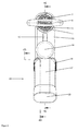
- Figur 1:
- eine schematische perspektivische Ansicht einer erfindungsgemäßen Vorrichtung als Full-Prepacked-Mischsystem;
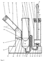
- Figur 2:
- die
Vorrichtung nach Figur 1 in einer Aufsicht mit zwei Schnittebenen A und B; - Figur 3:
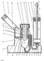
- die Vorrichtung
nach den Figuren 1 und2 in einer schematischen Querschnittansicht entsprechend der Schnittebene A nachFigur 2 ; - Figur 4:
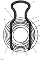
- einen Teilbereich der Vorrichtung nach
den Figuren 1 ,2 und3 in einer schematischen Querschnittansicht entsprechend der SchnittebeneB nach Figur 2 ; - Figur 5:
- eine schematische perspektivische Ansicht einer alternativen erfindungsgemäßen Vorrichtung als Full-Prepacked-Mischsystem;
- Figur 6:
- die Vorrichtung nach
Figur 5 in einer schematischen Querschnittansicht; und - Figur 7:
- eine schematische Querschnittansicht eines Teilbereichs der Vorrichtung nach
den Figuren 4 und5 und zwar des Hohlzylinders mit einer Spange als Arretierung für eine Druckfeder.
- FIG. 1:
- a schematic perspective view of an apparatus according to the invention as a full-prepacked mixing system;
- FIG. 2:
- the device after
FIG. 1 in a plan view with two sectional planes A and B; - FIG. 3:
- the device according to the
FIGS. 1 and2 in a schematic cross-sectional view according to the sectional plane A afterFIG. 2 ; - FIG. 4:
- a portion of the device according to the
FIGS. 1 .2 and3 in a schematic cross-sectional view according to the sectional plane B toFIG. 2 ; - FIG. 5:
- a schematic perspective view of an alternative device according to the invention as a full-prepacked mixing system;
- FIG. 6:
- the device after
FIG. 5 in a schematic cross-sectional view; and - FIG. 7:
- a schematic cross-sectional view of a portion of the device according to the
FIGS. 4 and5 namely the hollow cylinder with a clasp as a lock for a compression spring.
In den Querschnittansichten der
Die
Die Vorrichtung umfasst eine Kartusche 1 in der ein Zementpulver als Ausgangskomponente des herzustellenden PMMA-Knochenzements enthalten ist. Auf der Oberseite (in den
Im Bereich eines Stutzens 8 an einem Standfuß 10 der Vorrichtung ist die Kartusche 1 mit dem Standfuß 10 lösbar befestigt. Einteilig mit dem Standfuß 10 ausgeführt ist an dessen Oberseite ein Hohlzylinder 12 angeordnet, in dem ein innen passender Pumpkolben 14 angeordnet ist, der sich in das Innere des Hohlzylinders 12 einpressen beziehungsweise eindrücken lässt (in den
Neben dem Hohlzylinder 12 ist am Standfuß 10 noch ein Anschlussstutzen 18 vorgesehen, der ein Teil eines Anschlusses 20 für einen Monomer-Behälter 46 der Vorrichtung bildet. Der Anschluss 20 für den Monomer-Behälter 46 umfasst neben dem Anschlussstutzen 18 noch eine elastische Aufnahme 21 für den Monomer-Behälter 46 und einen Deckel 22, mit dem der Anschluss 20 für den Monomer-Behälter 46 nach außen abschließbar ist, nachdem der Monomer-Behälter 46 einsteckt wurde. Der Monomer-Behälter 46 ist im Inneren des Anschlusses 20 und in der Vorrichtung angeordnet. Der Monomer-Behälter 46 ist eine Glasampulle, die mit einer Monomerflüssigkeit als zweiter Komponente für den herzustellenden PMMA-Knochenzement gefüllt ist. Die elastische Aufnahme 21 besteht aus Gummi oder einem anderen elastischen Kunststoff.In addition to the
Weitere Details zum Aufbau der Vorrichtung sind in den
Zum Anschließen der Kartusche 1 an den Standfuß 10 ist ein Standfuß-Anschluss 34 mit einem Außengewinde als Verbindung zur Kartusche 1 vorgesehen, in dem ein pulverundurchlässiger und flüssigkeitsdurchlässiger Filter 32 angeordnet ist. Auf der dem Austragskolben 2 gegenüberliegenden Seite des Innenraums 24 der Kartusche 1 ist ein zum Außengewinde des Standfuß-Anschlusses 34 passender Kartuschenanschluss 36 mit Innengewinde vorgesehen. Der Kartuschenanschluss 36 begrenzt die Austragsöffnung der Kartusche 1. Der Kartuschenanschluss 36 ist auf den Standfuß-Anschluss 34 aufgeschraubt und schließt mit diesem dicht ab.For connecting the
Zwischen dem Hohlzylinder 12 und dem Innenraum 24 der Kartusche 1 ist eine Verbindungsleitung 38 vorgesehen, die den Hohlzylinder 12 mit dem Innenraum 24 der Kartusche 1 verbindet. An der Einmündung in den Innenraum 24 der Kartusche 1 ist der Filter 32 angeordnet, der verhindert, dass Zementpulver aus dem Innenraum 24 der Kartusche 1 in die Verbindungsleitung 38 eindringt. Die Verbindungsleitung 38 bildet eine Schlaufe 40 mit einem hohen Scheitelpunkt, um ein unkontrolliertes Durchfließen der Monomerflüssigkeit durch die Verbindungsleitung 38 in den Innenraum 24 der Kartusche 1 zu verhindern. Ein Gehäuse 16 mit einem kleinen Sichtfenster ist zur Abdeckung und visuellen Kontrolle der Schlaufe 40 vorgesehen. Der Stutzen 8, Standfuß 10, der Hohlzylinder 12, das Gehäuse 16 und der Anschlussstutzen 18 für den Monomer-Behälter 46 sind einteilig aus einem Kunststoff beispielsweise durch Spritzgießen hergestellt. Der Hohlzylinder 12 ist an der Unterseite (in
An einer Mantelfläche des Hohlzylinders 12, direkt unterhalb der unteren Fläche 42 des Pumpkolbens 14, ist eine Einmündung 44 von dem Anschluss 20 für den Monomer-Behälter 46 in den Hohlzylinder 12 vorgesehen. Die Einmündung 44 bildet ein Leitungsmittel für die Monomerflüssigkeit, so dass die Einmündung 44 als Teil einer Verbindungsleitung 38, 44 für die Monomerflüssigkeit aufgefasst werden kann, in der der Hohlzylinder 12 angeordnet ist.On an outer surface of the
In dem Anschluss 20 für den Monomer-Behälter 46 ist ein Sieb 45 oder Filter 45 angeordnet, mit dem Bruchstücke und Teile des geöffneten Monomer-Behälters 46 abgefangen werden können. Der Monomer-Behälter 46 ist eine Glasampulle 46 mit einem abbrechbaren Ampullenkopf 47 und einem aufbrechbaren Genick, wobei das Genick den Ampullenkopf 47 mit dem Körper der Ampulle 46 verbindet. Durch die Elastizität der Aufnahme 21 für den Monomer-Behälter 46 und durch die Verdickung der Aufnahme 21 im Bereich des Genicks kann durch Biegen der Aufnahme 21 mit dem Monomer-Behälter 46 darin der Kopf 47 des Monomer-Behälters 46 abgebrochen werden. Die Aufnahme 21 mit der entsprechenden Form, insbesondere mit der Verdickung im Bereich des Genicks, bildet dadurch ein Öffnungsmittel 21 zum Öffnen des Monomer-Behälters 46. Andere Öffnungsmittel zum Abscheren des Kopfs 47 des Monomer-Behälters 46 sind ebenfalls umsetzbar.In the
Im Anschlussstutzen 18 ist unterhalb des Siebs 45 beziehungsweise des Filters 45 eine geneigte Bodenfläche 48 vorgesehen, die in Richtung der Einmündung 44 geneigt ist. Dadurch kann die gesamte Monomerflüssigkeit aus dem Monomer-Behälter 46 durch die Einmündung 44 in den Hohlzylinder 12 fließen.In the connecting
Ein erfindungsgemäßes Verfahren kann mit der Vorrichtung nach den
Der Pumpkolben 14 kann anschließend vollständig oder teilweise in den Hohlzylinder 12 eingedrückt werden, um die gewünschte Menge Monomerflüssigkeit aus dem Hohlzylinder 12 durch die Verbindungsleitung 38 in den Innenraum 24 der Kartusche 1 zu überführen beziehungsweise zu pressen. Die Menge der eingepressten Monomerflüssigkeit lässt sich durch unterschiedlich tiefes Einschieben des Pumpkolbens 14 in den Hohlzylinder 12 einstellen. Hierzu können Markierungen (nicht gezeigt) außen am Pumpkolben 14 vorgesehen sein, oder am Hohlzylinder 12 sind Markierungen angebracht, und der Hohlzylinder 12 besteht aus einem transparenten Material. Die Monomerflüssigkeit wird durch den Filter 32 in den Innenraum 24 der Kartusche 1 gepresst und steigt dort an und mischt sich mit dem Zementpulver, das in dem Innenraum 24 der Kartusche 1 gelagert ist.The
Nachdem die gewünschte Menge in den Innenraum 24 der Kartusche 1 eingefüllt wurde, wird durch Hineinschieben, Herausziehen und Drehen der Mischeinrichtung 26 beziehungsweise der Mischstange 4 mit Hilfe des Griffstücks 6 manuell die Monomerflüssigkeit und das Zementpulver gemischt und so der Zementteig beziehungsweise der PMMA-Knochenzement gemischt. Nach erfolgter Durchmischung wird die Mischstange 4 bis zum Anschlag aus dem Innenraum 24 der Kartusche 1 herausgezogen und abgebrochen, damit sie später nicht stört. Gegebenenfalls kann eine Arretierung des Austragskolbens 2 gelöst werden. Anschließend wird die Kartusche 1 vom Standfuß 10 abgeschraubt und ein Austragsrohr (nicht gezeigt) kann auf das Innengewinde am Kartuschenanschluss 36 geschraubt werden. Anschließend kann der fertig gemischte Knochenzement aus dem Innenraum der Kartusche durch die Austragsöffnung und das Austragsrohr durch Einpressen des Austragskolbens 2 ausgetrieben und appliziert werden.After the desired amount has been filled into the
Die
Die Vorrichtung umfasst eine Kartusche 51 in der ein Zementpulver als Ausgangskomponente des herzustellenden PMMA-Knochenzements enthalten ist. Auf der Oberseite (in den
Im Bereich eines Stutzens 58 an einem Standfuß 60 der Vorrichtung ist die Kartusche 51 mit dem Standfuß 60 lösbar befestigt. Einteilig mit dem Standfuß 60 ausgeführt ist an dessen Oberseite ein Hohlzylinder 62 angeordnet, der durch einen Schraubdeckel 63 verschlossen ist. In dem Hohlzylinder 62 ist ein passender Pumpkolben 64 angeordnet ist, der sich in das Innere des Hohlzylinders 62 einpressen beziehungsweise eindrücken lässt (in den
Neben dem Hohlzylinder 62 ist am Standfuß 60 noch ein Anschlussstutzen 68 vorgesehen, der ein Teil eines Anschlusses 70 für einen Monomer-Behälter 96 der Vorrichtung bildet. Der Anschluss 70 für den Monomer-Behälter 96 umfasst neben dem Anschlussstutzen 68 noch eine elastische Aufnahme 71 für den Monomer-Behälter 96 und einen Deckel 72, mit dem der Anschluss 70 für den Monomer-Behälter 96 nach außen abschließbar ist, nachdem der Monomer-Behälter 96 einsteckt wurde. Der Monomer-Behälter 96 ist im Inneren des Anschlusses 70 und in der Vorrichtung angeordnet. Der Monomer-Behälter 96 ist eine Glasampulle, die mit einer Monomerflüssigkeit als zweiter Komponente für den herzustellenden PMMA-Knochenzement gefüllt ist. Die elastische Aufnahme 71 besteht aus Gummi oder einem anderen elastischen Kunststoff.In addition to the
Weitere Details zum Aufbau der Vorrichtung sind in
Zwischen dem Hohlzylinder 62 und dem Innenraum 74 der Kartusche 51 ist eine Verbindungsleitung 88 vorgesehen, die den Hohlzylinder 62 mit dem Innenraum 74 der Kartusche 51 verbindet. An der Einmündung in den Innenraum 74 der Kartusche 51 ist der Filter 82 angeordnet, der verhindert, dass Zementpulver aus dem Innenraum 74 der Kartusche 51 in die Verbindungsleitung 88 eindringt. Die Verbindungsleitung 88 bildet eine Schlaufe 90 mit einem hohen Scheitelpunkt, um ein unkontrolliertes Durchfließen der Monomerflüssigkeit durch die Verbindungsleitung 88 in den Innenraum 74 der Kartusche 51 zu verhindern. Ein Gehäuse 66 mit einem kleinen Sichtfenster ist zur Abdeckung und visuellen Kontrolle der Schlaufe 80 vorgesehen.Between the
Der Stutzen 58, Standfuß 60, der Hohlzylinder 62, das Gehäuse 66 und der Anschlussstutzen 68 für den Monomer-Behälter 96 sind einteilig aus einem Kunststoff beispielsweise durch Spritzgießen hergestellt. Der Hohlzylinder 62 ist an der Unterseite (in
An einer Mantelfläche des Hohlzylinders 62, direkt unterhalb der unteren Fläche 92 des Pumpkolbens 64, ist eine Einmündung 94 von dem Anschluss 70 für den Monomer-Behälter 96 in den Hohlzylinder 62 vorgesehen. Die Einmündung 94 bildet ein Leitungsmittel für die Monomerflüssigkeit, so dass die Einmündung 94 als Teil einer Verbindungsleitung 88, 94 für die Monomerflüssigkeit aufgefasst werden kann, in der der Hohlzylinder 62 angeordnet ist.On a lateral surface of the
In dem Anschluss 70 für den Monomer-Behälter 96 ist ein Sieb 95 oder Filter 95 angeordnet, mit dem Bruchstücke und Teile des geöffneten Monomer-Behälters 96 abgefangen werden können. Der Monomer-Behälter 96 ist eine Glasampulle 96 mit einem abbrechbaren Ampullenkopf 97 und einem aufbrechbaren Genick, wobei das Genick den Ampullenkopf 97 mit dem Körper der Ampulle 96 verbindet. Durch die Elastizität der Aufnahme 71 für den Monomer-Behälter 96 und durch die Verdickung der Aufnahme 71 im Bereich des Genicks kann durch Biegen der Aufnahme 71 mit dem Monomer-Behälter 96 darin der Kopf 97 des Monomer-Behälters 96 abgebrochen werden. Die Aufnahme 71 mit der entsprechenden Form, insbesondere mit der Verdickung im Bereich des Genicks, bildet dadurch ein Öffnungsmittel 71 zum Öffnen des Monomer-Behälters 96. Andere Öffnungsmittel zum Abscheren des Kopfs 97 des Monomer-Behälters 96 sind ebenfalls umsetzbar.In the
Im Anschlussstutzen 68 ist unterhalb des Siebs 95 beziehungsweise des Filters 95 eine geneigte Bodenfläche 98 vorgesehen, die in Richtung der Einmündung 94 geneigt ist. Dadurch kann die gesamte Monomerflüssigkeit aus dem Monomer-Behälter 96 durch die Einmündung 94 in den Hohlzylinder 62 fließen.In the connecting
Ein erfindungsgemäßes Verfahren kann mit der Vorrichtung nach den
Danach wird die Spange 65 aus der Vorrichtung gezogen und damit der Pumpkolben entarretiert. Der Pumpkolben 64 wird aufgrund der meachnischen Spannung der Druckfeder 67 anschließend vollständig in den Hohlzylinder 62 eingedrückt und dadurch die Monomerflüssigkeit aus dem Hohlzylinder 62 durch die Verbindungsleitung 88 in den Innenraum 74 der Kartusche 51 überführt beziehungsweise gepresst. Die Monomerflüssigkeit wird durch den Filter 82 in den Innenraum 74 der Kartusche 51 gepresst und steigt dort an und mischt sich mit dem Zementpulver, das in dem Innenraum 74 der Kartusche 51 gelagert ist.Thereafter, the
Nachdem die Monomerflüssigkeit in den Innenraum 74 der Kartusche 51 eingefüllt wurde, wird durch Hineinschieben, Herausziehen und Drehen der Mischeinrichtung 76 beziehungsweise der Mischstange 54 mit Hilfe des Griffstücks 56 manuell die Monomerflüssigkeit und das Zementpulver gemischt und so der Zementteig beziehungsweise der PMMA-Knochenzement gemischt. Nach erfolgter Durchmischung wird die Mischstange 54 bis zum Anschlag aus dem Innenraum 74 der Kartusche 51 herausgezogen und abgebrochen, damit sie später nicht stört. Gegebenenfalls kann eine Arretierung des Austragskolbens 52 gelöst werden. Anschließend wird die Kartusche 51 vom Standfuß 60 abgeschraubt und ein Austragsrohr (nicht gezeigt) kann auf das Innengewinde am Kartuschenanschluss 86 geschraubt werden. Anschließend kann der fertig gemischte Knochenzement aus dem Innenraum der Kartusche durch die Austragsöffnung und das Austragsrohr durch Einpressen des Austragskolbens 52 ausgetrieben und appliziert werden.After the monomer liquid is filled in the
Die in der voranstehenden Beschreibung, sowie den Ansprüchen, Figuren und Ausführungsbeispielen offenbarten Merkmale der Erfindung können sowohl einzeln, als auch in jeder beliebigen Kombination für die Verwirklichung der Erfindung in ihren verschiedenen Ausführungsformen wesentlich sein.The features of the invention disclosed in the foregoing description, as well as the claims, figures and embodiments may be essential both individually and in any combination for the realization of the invention in its various embodiments.
- 1, 511, 51
- Kartuschecartridge
- 2, 522, 52
- Austragskolbendelivery plunger
- 3, 533, 53
- Vakuumanschlussvacuum connection
- 4, 544, 54
- Mischstangemixing rod
- 6, 566, 56
- Griffstückgrip
- 8, 588, 58
- StutzenSupport
- 10, 6010, 60
- Standfußstand
- 12, 6212, 62
- Hohlzylinderhollow cylinder
- 14, 6414, 64
- Pumpkolbenpump piston
- 16, 6616, 66
- Gehäuse für Schlaufe der VerbindungsleitungHousing for loop of the connecting line
- 18, 6818, 68
- Anschlussstutzenspigot
- 20, 7020, 70
- Anschluss für den Monomer-BehälterConnection for the monomer container
- 21, 7121, 71
- Elastische Aufnahme für den Monomer-Behälter / ÖffnungsmittelElastic receiver for the monomer container / opening means
- 22, 7222, 72
- Deckelcover
- 24, 7424, 74
- Innenraum der KartuscheInterior of the cartouche
- 26, 7626, 76
- Mischflügel / MischeinrichtungMixing blades / mixing device
- 28, 7828, 78
- Sterilisationskolbensterilization piston
- 29, 7929, 79
- Dichtungpoetry
- 30, 8030, 80
- Dichtungskolbenseal piston
- 32, 8232, 82
- Pulverundurchlässiger und Flüssigkeitsdurchlässiger FilterPowder-impermeable and liquid-permeable filter
- 34, 8434, 84
- Standfuß-Anschluss mit AußengewindeBase connection with external thread
- 36, 8636, 86
- Kartuschenanschluss mit InnengewindeCartridge connection with internal thread
- 38, 8838, 88
- Verbindungsleitungconnecting line
- 40, 9040, 90
- Schlaufe der VerbindungsleitungLoop of the connecting line
- 41, 9141, 91
- Boden des HohlzylindersBottom of the hollow cylinder
- 42, 9242, 92
- Untere Fläche des PumpkolbensLower surface of the pump piston
- 43, 9343, 93
- Dichtungpoetry
- 44, 9444, 94
- Einmündung in den Hohlzylinder / VerbindungsleitungJunction in the hollow cylinder / connecting line
- 45, 9545, 95
- Sieb / FilterSieve / filter
- 46, 9646, 96
- Glasampulle / Monomer-BehälterGlass ampoule / monomer container
- 47, 9747, 97
- Kopf der Glasampulle / Kopf des Monomer-BehältersHead of glass ampoule / head of monomer tank
- 48, 9848, 98
- Geneigte Bodenfläche des Anschlusses für den Monomer-BehälterInclined bottom surface of the connector for the monomer tank
- 6363
- Schraubdeckelscrew
- 6565
- Arretierung / SpangeLocking / clasp
- 6767
- Gespannte DruckfederTensioned compression spring
Claims (26)
einen Monomer-Behälter (46, 96) für eine Monomerflüssigkeit und/oder einen Anschluss (20, 70) zur Befestigung eines Monomer-Behälters (46, 96) für eine Monomerflüssigkeit, so dass der Monomer-Behälter (46, 96) in der Vorrichtung derart zu öffnen ist, dass die Monomerflüssigkeit aus dem Monomer-Behälter (46, 96) in die Vorrichtung ausläuft,
eine Verbindungsleitung (38, 88), durch die die Monomerflüssigkeit in den Innenraum (24, 74) der Kartusche (1, 51) zu leiten ist,
dadurch gekennzeichnet, dass
ein Hohlzylinder (12, 62) mit der Verbindungsleitung (38, 88) verbunden ist und der Hohlzylinder (12, 62) zwischen dem Monomer-Behälter (46, 96) oder dem Anschluss für den Monomer-Behälter (46, 96) und dem Innenraum (24, 74) der Kartusche (1, 51) angeordnet ist, wobei in dem Hohlzylinder (12, 62) ein axial im Hohlzylinder (12, 62) verschiebbarer Pumpkolben (14, 64) angeordnet ist, wobei die Monomerflüssigkeit aus dem geöffneten Monomer-Behälter (46, 96) in den Hohlzylinder (12, 62) fließen kann und die Verbindungsleitung (38, 88) den Hohlzylinder (12, 62) mit dem Innenraum (24, 74) der Kartusche (1, 51) derart verbindet, dass mit dem Pumpkolben (14, 64) Monomerflüssigkeit aus dem Hohlzylinder (12, 62) durch Betätigen des Pumpkolbens (14, 64) durch die Verbindungsleitung (38, 88) in den Innenraum (24, 74) der Kartusche (1, 51) zu drücken ist.Apparatus for mixing polymethyl methacrylate bone cement and for storing the starting components of the bone cement, in particular a monomer fluid and a cement powder as starting components of the bone cement, the apparatus comprising a cartridge (1, 51) with an interior (24, 74) for mixing the bone cement, the is closed on one side by a movable discharge piston (2, 52),
a monomer tank (46, 96) for a monomer liquid and / or a port (20, 70) for mounting a monomer tank (46, 96) for a monomer liquid, such that the monomer tank (46, 96) in the Open device such that the monomer liquid from the monomer container (46, 96) expires into the device,
a connecting line (38, 88) through which the monomer liquid is to be conducted into the interior space (24, 74) of the cartridge (1, 51),
characterized in that
a hollow cylinder (12, 62) is connected to the connecting line (38, 88) and the hollow cylinder (12, 62) is connected between the monomer container (46, 96) or the connection for the monomer container (46, 96) and the Interior space (24, 74) of the cartridge (1, 51) is arranged, wherein in the hollow cylinder (12, 62) an axially in the hollow cylinder (12, 62) displaceable pump piston (14, 64) is arranged, wherein the monomer liquid from the open Monomer container (46, 96) in the hollow cylinder (12, 62) can flow and the connecting line (38, 88) the hollow cylinder (12, 62) with the interior (24, 74) of the cartridge (1, 51) so connects in that monomer liquid from the hollow cylinder (12, 62) is conveyed to the pump piston (14, 64) by actuating the pump piston (14, 64) through the connecting line (38, 88) into the interior space (24, 74) of the cartridge (1, 51 ) is to be pressed.
das Zementpulver im Innenraum (24, 74) der Kartusche (1, 51) enthalten ist.Device according to one of the preceding claims, characterized in that
the cement powder in the interior (24, 74) of the cartridge (1, 51) is included.
zwischen der Verbindungsleitung (38, 88) und dem Innenraum (24, 74) der Kartusche (1, 51) ein für das Zementpulver undurchlässiger und für die Monomerflüssigkeit durchlässiger Filter (32, 82) angeordnet ist.Device according to one of the preceding claims, characterized in that
between the connecting line (38, 88) and the interior (24, 74) of the cartridge (1, 51) is arranged a filter for the cement powder impermeable and for the monomer liquid permeable filter (32, 82).
die Vorrichtung einen Standfuß (10, 60) aufweist, in dem zumindest ein Teil der Verbindungsleitung (38, 88) angeordnet ist, wobei die Kartusche (1, 51) lösbar mit dem Standfuß (10, 60) verbunden ist, insbesondere über ein Schraubgewinde lösbar mit dem Standfuß (10, 60) verbunden ist, wobei bevorzugt gegebenenfalls der für das Zementpulver undurchlässige und für die Monomerflüssigkeit durchlässige Filter (32, 82) in dem Standfuß (10, 60) der Vorrichtung angeordnet ist, besonders bevorzugt in der Verbindung (34, 84) zur Kartusche (1, 51) des Standfußes (10, 60) angeordnet ist.Device according to one of the preceding claims, characterized in that
the device comprises a pedestal (10, 60) in which at least part of the connecting duct (38, 88) is arranged, the cartridge (1, 51) being detachably connected to the pedestal (10, 60), in particular via a screw thread detachably connected to the base (10, 60), preferably wherein the cement powder impermeable and monomer liquid permeable filter (32, 82) is preferably disposed in the base (10, 60) of the device, more preferably in the compound ( 34, 84) to the cartridge (1, 51) of the base (10, 60) is arranged.
der Monomer-Behälter (46, 96) für die Monomerflüssigkeit oder der Anschluss (20, 70) zur Befestigung des Monomer-Behälters (46, 96) an einer Mantelfläche des Hohlzylinders (12, 62) in den Hohlzylinder (12, 62) mündet, bevorzugt unmittelbar unterhalb des Pumpkolbens (14, 64) in den Hohlzylinder (12, 62) mündet.Device according to one of the preceding claims, characterized in that
the monomer container (46, 96) for the monomer liquid or the connection (20, 70) for fastening the monomer container (46, 96) on a lateral surface of the hollow cylinder (12, 62) in the hollow cylinder (12, 62) opens , preferably immediately below the pump piston (14, 64) in the hollow cylinder (12, 62) opens.
die Vorrichtung ein Öffnungsmittel (21, 71) zum Öffnen des Monomer-Behälters (46, 96) aufweist, mit dem der Monomer-Behälter (46, 96) innerhalb der Vorrichtung zu öffnen ist, wobei bevorzugt in der Verbindung zum Hohlzylinder (12, 62) ein Sieb (45, 95) oder ein Filter (45, 95) angeordnet ist, mit dem Bruchstücke oder Fetzen des geöffneten Monomer-Behälters (46, 96) zurückgehalten werden können.Device according to one of the preceding claims, characterized in that
the apparatus comprises opening means (21, 71) for opening the monomer container (46, 96), with which the monomer container (46, 96) can be opened inside the apparatus, wherein preferably in the connection to the hollow cylinder (12, 62), a screen (45, 95) or a filter (45, 95) is arranged, with the fragments or shreds of the opened monomer container (46, 96) can be retained.
der Monomer-Behälter (46, 96) oberhalb der der Verbindung zum Hohlzylinder (12, 62) angeordnet ist.Device according to one of the preceding claims, characterized in that
the monomer container (46, 96) is arranged above the connection to the hollow cylinder (12, 62).
die Verbindungsleitung (38, 44, 88, 94) an der unteren Seite mit dem Hohlzylinder (12, 62) verbunden ist, bevorzugt am tiefsten Punkt des Hohlzylinders (12, 62) mit dem Hohlzylinder (12, 62) verbunden ist, wobei besonders bevorzugt der Pumpkolben (14, 64) auf der gegenüberliegenden Seite des Hohlzylinders (12, 62) angeordnet ist.Device according to one of the preceding claims, characterized in that
the connecting line (38, 44, 88, 94) is connected at the lower side to the hollow cylinder (12, 62), preferably at the lowest point of the hollow cylinder (12, 62) is connected to the hollow cylinder (12, 62), in particular Preferably, the pump piston (14, 64) on the opposite side of the hollow cylinder (12, 62) is arranged.
der Hohlzylinder (12, 62) auf der dem Pumpkolben (14, 64) gegenüberliegenden Seite einen kegelförmigen, halbkugelförmigen oder anderen sich nach unten verjüngenden Boden (41, 91) aufweist, wobei bevorzugt die dem Boden (41, 91) des Hohlzylinders (12, 62) zugewandte Fläche (42, 92) des Pumpkolbens (14, 64) eine Negativform des Bodens (41, 91) bildet.Device according to one of the preceding claims, characterized in that
the hollow cylinder (12, 62) on the pump piston (14, 64) opposite side has a conical, hemispherical or other downwardly tapering bottom (41, 91), wherein preferably the bottom (41, 91) of the hollow cylinder (12 , 62) facing surface (42, 92) of the pump piston (14, 64) forms a negative mold of the bottom (41, 91).
der Pumpkolben (14, 64) manuell axial im Hohlzylinder (12, 62) bewegt werden kann, bevorzugt manuell axial in den Hohlzylinder (12, 62) eingepresst werden kann.Device according to one of the preceding claims, characterized in that
the pump piston (14, 64) manually axially in the hollow cylinder (12, 62) can be moved, preferably manually axially into the hollow cylinder (12, 62) can be pressed.
der Hohlzylinder (12, 62) transparent ist und Markierungen zur Füllstandsmenge einer Flüssigkeit in dem Hohlzylinder (12, 62) aufweist.Device according to one of the preceding claims, characterized in that
the hollow cylinder (12, 62) is transparent and has markings for the level of a liquid in the hollow cylinder (12, 62).
der Hohlzylinder (12, 62) ein Innengewinde aufweist und der Pumpkolben (14, 64) ein dazu passendes Außengewinde aufweist, so dass der Pumpkolben (14, 64) in den Hohlzylinder (12, 62) einschraubbar ist, um die Monomerflüssigkeit aus dem Hohlzylinder (12, 62) in den Innenraum (24, 74) der Kartusche (1, 51) zu pressen.Device according to one of the preceding claims, characterized in that
the hollow cylinder (12, 62) has an internal thread and the pump piston (14, 64) has a matching external thread, so that the pump piston (14, 64) in the hollow cylinder (12, 62) can be screwed to the monomer liquid from the hollow cylinder (12, 62) in the interior (24, 74) of the cartridge (1, 51) to press.
die Vorrichtung eine gespannte Druckfeder (67) und eine Arretierung (65) aufweist, wobei die Druckfeder (67) und/oder der Pumpkolben (64) mit der Arretierung (65) lösbar arretiert ist oder sind, wobei bei gelöster Arretierung (65) die Druckfeder (67) einen Druck auf den Pumpkolben (64) ausübt, so dass der Pumpkolben (64) in den Hohlzylinder (62) gepresst wird.Device according to one of claims 1 to 14, characterized in that
the device comprises a tensioned compression spring (67) and a detent (65), wherein the compression spring (67) and / or the pump piston (64) with the detent (65) is releasably locked or are, wherein when dissolved detent (65) the Compressive spring (67) exerts a pressure on the pump piston (64), so that the pump piston (64) is pressed into the hollow cylinder (62).
der Austragskolben (2, 52) mit einer lösbaren Rastvorrichtung mit der Kartusche (1, 51) verbunden ist, wobei die Rastvorrichtung manuell, insbesondere durch axiale Krafteinwirkung lösbar ist, so dass der Austragskolben (2, 52) axial im Innenraum (24, 74) der Kartusche (1, 51) bewegt werden kann.Device according to one of the preceding claims, characterized in that
the discharge piston (2, 52) is connected to the cartridge (1, 51) with a detachable latching device, wherein the latching device can be released manually, in particular by axial force, so that the discharge piston (2, 52) axially in the interior (24, 74 ) of the cartridge (1, 51) can be moved.
die Verbindungsleitung (38, 44, 88, 94) zwischen dem Hohlzylinder (12, 62) und dem Innenraum (24, 74) der Kartusche (1, 51) eine nach oben weisende Schlaufe (40, 90) aufweist, wobei der höchste Punkt der Schlaufe (40, 90) oberhalb der Einmündung (44, 94) des Monomer-Behälters (46, 96) oder des Anschlusses (20, 70) für den Monomer-Behälter (46, 96) in den Hohlzylinder (12, 62) liegt.Device according to one of the preceding claims, characterized in that
the connecting line (38, 44, 88, 94) between the hollow cylinder (12, 62) and the interior (24, 74) of the cartridge (1, 51) has an upwardly pointing loop (40, 90), wherein the highest point the loop (40, 90) above the mouth (44, 94) of the monomer container (46, 96) or the connection (20, 70) for the monomer container (46, 96) into the hollow cylinder (12, 62) lies.
das Volumen im Hohlzylinder (12, 62) kleiner oder gleich dem Volumen der Monomerflüssigkeit in dem Monomer-Behälter (46, 96) ist.Device according to one of the preceding claims, characterized in that
the volume in the hollow cylinder (12, 62) is less than or equal to the volume of monomer liquid in the monomer container (46, 96).
der Innenraum (24, 74) der Kartusche (1, 51) an der unteren Seite mit der Verbindungsleitung (38, 88) flüssigkeitsdurchlässig verbunden ist.Device according to one of the preceding claims, characterized in that
the inner space (24, 74) of the cartridge (1, 51) is connected in a liquid-permeable manner at the lower side to the connecting line (38, 88).
der Monomer-Behälter (46, 96) geöffnet wird, in dem ein Öffnungsmittel (21, 71) bedient oder ausgelöst wird, wobei bevorzugt der Monomer-Behälter (46, 96) durch das Öffnungsmittel (21, 71) aufgebrochen wird.Method according to one of claims 21 to 23, characterized in that
the monomer container (46, 96) is opened, in which an opening means (21, 71) is operated or triggered, wherein preferably the monomer container (46, 96) is broken by the opening means (21, 71).
der Pumpkolben (14, 64) mit einem gespannten elastischen Federelement (67) in den Hohlzylinder (12, 62) eingedrückt wird, wobei hierfür vorzugsweise zuvor eine Arretierung (65) gelöst wird, die in den Pumpkolben (14, 64) und/oder das Federelement (67) greift.Method according to one of claims 21 to 24, characterized in that
the pump piston (14, 64) with a tensioned elastic spring element (67) in the hollow cylinder (12, 62) is pressed, for this purpose, preferably a detent (65) is dissolved in the pump piston (14, 64) and / or the spring element (67) engages.
die Kartusche (1, 51) mit dem fertig gemischten Zementteig von der Verbindungsleitung (38, 44, 88, 94), dem Hohlzylinder (12, 62) und dem Monomer-Behälter (46, 96) gelöst wird und der fertig gemischte Zementteig durch Vortreiben eines Austragskolbens (2, 52), der axial beweglich in der Kartusche (1, 51) gelagert ist und der den Innenraum (24, 74) der Kartusche (1, 51) auf einer Seite begrenzt, aus dem Innenraum (24, 74) der Kartusche (1, 51) ausgetragen wird.Method according to one of claims 21 to 25, characterized in that
the cartridge (1, 51) with the ready-mixed cement dough from the connecting line (38, 44, 88, 94), the hollow cylinder (12, 62) and the monomer container (46, 96) is released and the ready-mixed cement dough through Driving a discharge piston (2, 52) axially movably mounted in the cartridge (1, 51) and delimiting the inner space (24, 74) of the cartridge (1, 51) on one side from the inner space (24, 74 ) of the cartridge (1, 51) is discharged.
Applications Claiming Priority (1)
| Application Number | Priority Date | Filing Date | Title |
|---|---|---|---|
| DE102015106899.0A DE102015106899B3 (en) | 2015-05-04 | 2015-05-04 | Device for mixing and storing polymethyl methacrylate bone cement |
Publications (2)
| Publication Number | Publication Date |
|---|---|
| EP3093067A1 true EP3093067A1 (en) | 2016-11-16 |
| EP3093067B1 EP3093067B1 (en) | 2020-01-22 |
Family
ID=54010850
Family Applications (1)
| Application Number | Title | Priority Date | Filing Date |
|---|---|---|---|
| EP15180189.1A Active EP3093067B1 (en) | 2015-05-04 | 2015-08-07 | Device and method for mixing and storing of polymethylmethacrylate bone cement |
Country Status (8)
| Country | Link |
|---|---|
| US (2) | US10045806B2 (en) |
| EP (1) | EP3093067B1 (en) |
| JP (1) | JP6091576B2 (en) |
| CN (1) | CN106113307B (en) |
| AU (1) | AU2015213268B2 (en) |
| CA (1) | CA2900121C (en) |
| DE (1) | DE102015106899B3 (en) |
| TW (1) | TWI630998B (en) |
Cited By (2)
| Publication number | Priority date | Publication date | Assignee | Title |
|---|---|---|---|---|
| US10293078B2 (en) | 2015-09-10 | 2019-05-21 | Heraeus Medical Gmbh | Polymethylmethacrylate bone cement with adjustable initial viscosity, and method for producing a bone cement dough with variable initial viscosity |
| EP4299169A1 (en) | 2022-06-30 | 2024-01-03 | Heraeus Medical GmbH | Device and method for producing bone cement |
Families Citing this family (9)
| Publication number | Priority date | Publication date | Assignee | Title |
|---|---|---|---|---|
| DE102015108783B3 (en) * | 2015-06-03 | 2016-07-14 | Heraeus Medical Gmbh | Device for mixing and storing polymethyl methacrylate bone cement |
| USD849267S1 (en) * | 2016-04-25 | 2019-05-21 | Heraeus Medical Gmbh | Mixing device for bone cement |
| EP4234611A1 (en) * | 2016-07-22 | 2023-08-30 | Sekisui Plastics Co., Ltd. | Generally spherical resin particles formed of thermoplastic resin, method for producing same and use of same |
| WO2018089915A2 (en) * | 2016-11-14 | 2018-05-17 | Fusion Packaging I, LP | Dispenser with above-bottle replenishing product mixture |
| WO2019067485A2 (en) * | 2017-09-26 | 2019-04-04 | Schlumberger Technology Corporation | Apparatus for mixing fluids and solids with separate injector port |
| DE102018101041A1 (en) * | 2018-01-18 | 2019-07-18 | Heraeus Medical Gmbh | Bone cement applicator with sealable gassing opening |
| DE102018209784A1 (en) * | 2018-06-18 | 2019-12-19 | Heraeus Medical Gmbh | Bone cement applicator with retractable mixing stick and method for producing a bone cement |
| CN110666980B (en) * | 2019-11-12 | 2021-03-16 | 浙江远新环保科技有限公司 | Dry material injection device for slurry solidification |
| EP3838391A1 (en) | 2019-12-18 | 2021-06-23 | Heraeus Medical GmbH | Device for producing bone cement |
Citations (21)
| Publication number | Priority date | Publication date | Assignee | Title |
|---|---|---|---|---|
| US4671263A (en) | 1984-07-11 | 1987-06-09 | Klaus Draenert | Device and process for mixing and applying bone cement |
| DE3640279A1 (en) | 1985-12-23 | 1987-06-25 | Mit Ab | DEVICE FOR MIXING BONE CEMENT IN A VACUUM |
| US4973168A (en) | 1989-01-13 | 1990-11-27 | Chan Kwan Ho | Vacuum mixing/bone cement cartridge and kit |
| US5344232A (en) | 1991-09-30 | 1994-09-06 | Stryker Corporation | Bone cement mixing and loading apparatus |
| WO1994026403A1 (en) | 1993-05-10 | 1994-11-24 | Cemvac System Ab | Method and device for feeding components for bone cement into a mixing vessel for these |
| EP0692229A1 (en) | 1994-07-16 | 1996-01-17 | MERCK PATENT GmbH | Mixing and dispensing device for bone cement |
| US5586821A (en) | 1995-10-10 | 1996-12-24 | Zimmer, Inc. | Bone cement preparation kit |
| US5588745A (en) | 1994-09-02 | 1996-12-31 | Howmedica | Methods and apparatus for mixing bone cement components using an evacuated mixing chamber |
| US5997544A (en) | 1997-05-02 | 1999-12-07 | Merck Patent Gesellschaft Mit Beschrankter Haftung | Process and device for producing sterile-packed bone cement |
| WO1999067015A1 (en) | 1997-05-21 | 1999-12-29 | Nikomed Aps | An apparatus for preparing bone cement |
| US6033105A (en) | 1996-11-15 | 2000-03-07 | Barker; Donald | Integrated bone cement mixing and dispensing system |
| EP1005901A2 (en) | 1995-11-13 | 2000-06-07 | Cemvac System Aktiebolag | Method and device for mixing components for bone cement in a mixing vessel |
| WO2000035506A1 (en) | 1998-12-14 | 2000-06-22 | Ao Research Institute Davos | Method of bone cement preparation |
| EP1020167A2 (en) | 1999-01-14 | 2000-07-19 | Bristol-Myers Squibb Company | Apparatus and method for mixing and dispensing bone cement |
| DE20005333U1 (en) * | 2000-02-28 | 2001-07-12 | Coripharm Medizinprodukte Gmbh | Preparation and application device for implant materials |
| WO2006058153A1 (en) * | 2004-11-23 | 2006-06-01 | Smith & Nephew, Inc. | Composite mixer |
| DE60218464T2 (en) * | 2001-01-26 | 2007-11-08 | DePuy Spine, Inc., Raynham | INSERTION DEVICE FOR BONE TRANSPLANT |
| EP1886647A1 (en) | 2006-08-11 | 2008-02-13 | Biomet Cementing Technologies AB | Device at bone cement mixer |
| DE102009031178B3 (en) | 2009-06-29 | 2010-09-16 | Heraeus Medical Gmbh | Device for mixing and delivering bone cement |
| US8662736B2 (en) | 2010-07-29 | 2014-03-04 | Heraeus Medical Gmbh | Bone cement system |
| DE102010026496B4 (en) | 2010-07-07 | 2014-05-22 | Heraeus Medical Gmbh | ampoules breaker |
Family Cites Families (23)
| Publication number | Priority date | Publication date | Assignee | Title |
|---|---|---|---|---|
| US3390814A (en) * | 1965-09-24 | 1968-07-02 | Chem Dev Corp | Mixing device |
| US4889432A (en) * | 1989-02-07 | 1989-12-26 | Roosevelt Patterson | Dental mixer apparatus |
| US5674394A (en) * | 1995-03-24 | 1997-10-07 | Johnson & Johnson Medical, Inc. | Single use system for preparation of autologous plasma |
| DE19541594A1 (en) * | 1995-11-08 | 1997-05-15 | Pfeiffer Erich Gmbh & Co Kg | Discharge unit for media |
| US5779356A (en) * | 1996-02-21 | 1998-07-14 | Chan; Kwan-Ho | Apparatus and method for mixing first and second components of a bone cement in a vacuum |
| US6296149B1 (en) * | 1999-04-16 | 2001-10-02 | Depuy Orthopaedics, Inc. | Monomer delivery device for bone cement delivery system |
| WO2001047571A2 (en) | 1999-12-29 | 2001-07-05 | Regeneration Technologies, Inc. | System for reconstituting pastes and methods of using same |
| US6536937B1 (en) * | 2000-02-14 | 2003-03-25 | Telios Orthopedic Systems, Inc. | Self-contained base for a surgical cement mixing system, binding material mixing base, and surgical bone cement mixing system |
| US6689092B2 (en) * | 2000-03-03 | 2004-02-10 | Boehringer International Gmbh | Needle-less injector of miniature type |
| ITMO20030057A1 (en) | 2003-03-04 | 2004-09-05 | Sidam Di Azzolini Graziano E C S A S | DEVICE FOR THE PACKAGING, MIXING AND APPLICATION OF BONE CEMENT. |
| US8926623B2 (en) * | 2007-01-12 | 2015-01-06 | Warsaw Orthopedic, Inc. | System and method for forming porous bone filling material |
| US9180416B2 (en) * | 2008-04-21 | 2015-11-10 | Dfine, Inc. | System for use in bone cement preparation and delivery |
| US8944107B2 (en) * | 2008-07-29 | 2015-02-03 | Medmix Systems Ag | Device for opening a closed fluid container |
| WO2010083616A1 (en) * | 2009-01-21 | 2010-07-29 | Medmix Systems Ag | Mixing apparatus having display for pressure change |
| DE102010026497B4 (en) * | 2010-07-07 | 2014-04-03 | Heraeus Medical Gmbh | Vakuumzementiersystem |
| US8940046B2 (en) * | 2010-10-01 | 2015-01-27 | Maxx Orthopedics, Inc. | Method of implanting a prosthesis device using bone cement in liquid form |
| DE102010052323A1 (en) * | 2010-11-25 | 2012-05-31 | Heraeus Medical Gmbh | Cartridge with lockable delivery piston |
| EP2589821B1 (en) * | 2011-11-03 | 2017-08-02 | Heraeus Medical GmbH | Apparatus and method for the generation of vacuum for vacuum cementing systems |
| DE102011119377B3 (en) | 2011-11-25 | 2013-04-04 | Heraeus Medical Gmbh | Storage and mixing device for bone cement |
| DE102012008815B4 (en) * | 2012-05-07 | 2014-03-06 | Heraeus Medical Gmbh | Mixing device for multi-component systems |
| DE102012024710A1 (en) * | 2012-11-07 | 2014-05-08 | Heraeus Medical Gmbh | Device for mixing and discharging a pasty mass |
| DE102013011295A1 (en) * | 2013-07-08 | 2015-01-08 | Heraeus Medical Gmbh | Device for storing and mixing bone cement |
| DE102014108569B3 (en) * | 2014-06-18 | 2015-10-22 | Heraeus Medical Gmbh | Vacuum mixing system and method for mixing polymethyl methacrylate bone cement |
-
2015
- 2015-05-04 DE DE102015106899.0A patent/DE102015106899B3/en active Active
- 2015-08-07 EP EP15180189.1A patent/EP3093067B1/en active Active
- 2015-08-11 CA CA2900121A patent/CA2900121C/en active Active
- 2015-08-11 AU AU2015213268A patent/AU2015213268B2/en active Active
- 2015-08-13 US US14/825,483 patent/US10045806B2/en active Active
- 2015-08-26 TW TW104127989A patent/TWI630998B/en active
- 2015-10-01 JP JP2015195667A patent/JP6091576B2/en active Active
- 2015-10-30 CN CN201510720619.4A patent/CN106113307B/en active Active
-
2018
- 2018-07-13 US US16/034,618 patent/US11490940B2/en active Active
Patent Citations (26)
| Publication number | Priority date | Publication date | Assignee | Title |
|---|---|---|---|---|
| US4671263A (en) | 1984-07-11 | 1987-06-09 | Klaus Draenert | Device and process for mixing and applying bone cement |
| DE3640279A1 (en) | 1985-12-23 | 1987-06-25 | Mit Ab | DEVICE FOR MIXING BONE CEMENT IN A VACUUM |
| US4973168A (en) | 1989-01-13 | 1990-11-27 | Chan Kwan Ho | Vacuum mixing/bone cement cartridge and kit |
| US5100241A (en) | 1989-01-13 | 1992-03-31 | Chan Kwan Ho | Vacuum mixing/bone cement cartridge and kit |
| US5344232A (en) | 1991-09-30 | 1994-09-06 | Stryker Corporation | Bone cement mixing and loading apparatus |
| WO1994026403A1 (en) | 1993-05-10 | 1994-11-24 | Cemvac System Ab | Method and device for feeding components for bone cement into a mixing vessel for these |
| EP0692229A1 (en) | 1994-07-16 | 1996-01-17 | MERCK PATENT GmbH | Mixing and dispensing device for bone cement |
| US5588745A (en) | 1994-09-02 | 1996-12-31 | Howmedica | Methods and apparatus for mixing bone cement components using an evacuated mixing chamber |
| US5586821A (en) | 1995-10-10 | 1996-12-24 | Zimmer, Inc. | Bone cement preparation kit |
| US5624184A (en) | 1995-10-10 | 1997-04-29 | Chan; Kwan-Ho | Bone cement preparation kit having a breakable mixing shaft forming an output port |
| EP1016452A2 (en) | 1995-11-13 | 2000-07-05 | Cemvac System Aktiebolag | Method and device for mixing components for bone cement in a mixing vessel |
| EP1005901A2 (en) | 1995-11-13 | 2000-06-07 | Cemvac System Aktiebolag | Method and device for mixing components for bone cement in a mixing vessel |
| US6033105A (en) | 1996-11-15 | 2000-03-07 | Barker; Donald | Integrated bone cement mixing and dispensing system |
| US5997544A (en) | 1997-05-02 | 1999-12-07 | Merck Patent Gesellschaft Mit Beschrankter Haftung | Process and device for producing sterile-packed bone cement |
| WO1999067015A1 (en) | 1997-05-21 | 1999-12-29 | Nikomed Aps | An apparatus for preparing bone cement |
| DE69812726T2 (en) | 1998-12-14 | 2004-02-05 | Ao Research Institute | METHOD AND DEVICE FOR PRODUCING BONE CEMENT |
| WO2000035506A1 (en) | 1998-12-14 | 2000-06-22 | Ao Research Institute Davos | Method of bone cement preparation |
| US6709149B1 (en) | 1998-12-14 | 2004-03-23 | Ao Research Institute Davos | Method of bone cement preparation |
| EP1020167A2 (en) | 1999-01-14 | 2000-07-19 | Bristol-Myers Squibb Company | Apparatus and method for mixing and dispensing bone cement |
| DE20005333U1 (en) * | 2000-02-28 | 2001-07-12 | Coripharm Medizinprodukte Gmbh | Preparation and application device for implant materials |
| DE60218464T2 (en) * | 2001-01-26 | 2007-11-08 | DePuy Spine, Inc., Raynham | INSERTION DEVICE FOR BONE TRANSPLANT |
| WO2006058153A1 (en) * | 2004-11-23 | 2006-06-01 | Smith & Nephew, Inc. | Composite mixer |
| EP1886647A1 (en) | 2006-08-11 | 2008-02-13 | Biomet Cementing Technologies AB | Device at bone cement mixer |
| DE102009031178B3 (en) | 2009-06-29 | 2010-09-16 | Heraeus Medical Gmbh | Device for mixing and delivering bone cement |
| DE102010026496B4 (en) | 2010-07-07 | 2014-05-22 | Heraeus Medical Gmbh | ampoules breaker |
| US8662736B2 (en) | 2010-07-29 | 2014-03-04 | Heraeus Medical Gmbh | Bone cement system |
Non-Patent Citations (1)
| Title |
|---|
| CHARNLEY, J.: "Anchorage of the femoral head prosthesis of the shaft of the femur", J. BONE JOINT SURG., vol. 42, 1960, pages 28 - 30 |
Cited By (3)
| Publication number | Priority date | Publication date | Assignee | Title |
|---|---|---|---|---|
| US10293078B2 (en) | 2015-09-10 | 2019-05-21 | Heraeus Medical Gmbh | Polymethylmethacrylate bone cement with adjustable initial viscosity, and method for producing a bone cement dough with variable initial viscosity |
| EP3141267B1 (en) * | 2015-09-10 | 2019-11-20 | Heraeus Medical GmbH | Polymethylmethacrylate bone cement with adjustable initial viscosity and a method for producing a bone cement paste with variable initial viscosity |
| EP4299169A1 (en) | 2022-06-30 | 2024-01-03 | Heraeus Medical GmbH | Device and method for producing bone cement |
Also Published As
| Publication number | Publication date |
|---|---|
| AU2015213268B2 (en) | 2017-02-09 |
| US11490940B2 (en) | 2022-11-08 |
| US20180317991A1 (en) | 2018-11-08 |
| JP6091576B2 (en) | 2017-03-08 |
| CA2900121A1 (en) | 2016-11-04 |
| CN106113307B (en) | 2019-01-01 |
| TWI630998B (en) | 2018-08-01 |
| US20160324559A1 (en) | 2016-11-10 |
| TW201639686A (en) | 2016-11-16 |
| DE102015106899B3 (en) | 2016-07-14 |
| US10045806B2 (en) | 2018-08-14 |
| AU2015213268A1 (en) | 2016-11-24 |
| CA2900121C (en) | 2017-07-11 |
| JP2016209534A (en) | 2016-12-15 |
| CN106113307A (en) | 2016-11-16 |
| EP3093067B1 (en) | 2020-01-22 |
Similar Documents
| Publication | Publication Date | Title |
|---|---|---|
| DE102015106899B3 (en) | Device for mixing and storing polymethyl methacrylate bone cement | |
| EP3231505B1 (en) | Device for mixing and storing polymethyl methacrylate bone cement with pressure pump and ampoule breaker | |
| EP3150155B1 (en) | Device and method for storing and mixing a bone cement | |
| EP3100694B1 (en) | Device and method for mixing and storing polymethymethacrylate bone cement | |
| EP2957337B1 (en) | Vacuum mixing system and method for mixing of polymethylmethacrylate bone cement | |
| EP3395274B1 (en) | Bone cement application device with closure means at the output piston | |
| EP3403716B1 (en) | Bone cement applicator with hollow cylinder at the application piston | |
| DE102016110564B4 (en) | Storage and mixing device for bone cement with pressure pump | |
| EP3117895B1 (en) | Vacuum mixing system and method for the mixing of polymethylmethacrylate bone cement | |
| EP3260192B1 (en) | Storage and mixing device for producing a bone cement and method for mixing bone cement | |
| EP3584005B1 (en) | Bone cement applicator with retractable mixing rod and method for producing a bone cement | |
| DE102015121277B3 (en) | Vacuum mixing device with operating element, pressure and vacuum pump for mixing polymethyl methacrylate bone cement | |
| EP3584004B1 (en) | Bone cement applicator with retractable mixing rod and method for producing a bone cement | |
| EP3415226B1 (en) | Bone cement applicator with conduit element and closure holder | |
| EP3178546B1 (en) | Mixing device with operating element and pressure pump for mixing polymethylmethacrylate bone cement, and method | |
| EP3178545B1 (en) | Vacuum mixing device with operating element and pump for mixing polymethylmethacrylate bone cement, and method |
Legal Events
| Date | Code | Title | Description |
|---|---|---|---|
| PUAI | Public reference made under article 153(3) epc to a published international application that has entered the european phase |
Free format text: ORIGINAL CODE: 0009012 |
|
| 17P | Request for examination filed |
Effective date: 20150807 |
|
| AK | Designated contracting states |
Kind code of ref document: A1 Designated state(s): AL AT BE BG CH CY CZ DE DK EE ES FI FR GB GR HR HU IE IS IT LI LT LU LV MC MK MT NL NO PL PT RO RS SE SI SK SM TR |
|
| AX | Request for extension of the european patent |
Extension state: BA ME |
|
| GRAP | Despatch of communication of intention to grant a patent |
Free format text: ORIGINAL CODE: EPIDOSNIGR1 |
|
| STAA | Information on the status of an ep patent application or granted ep patent |
Free format text: STATUS: GRANT OF PATENT IS INTENDED |
|
| RIC1 | Information provided on ipc code assigned before grant |
Ipc: B01F 15/02 20060101ALI20190913BHEP Ipc: B01F 11/00 20060101ALI20190913BHEP Ipc: A61B 17/88 20060101ALI20190913BHEP Ipc: B01F 13/00 20060101AFI20190913BHEP Ipc: B01F 13/06 20060101ALI20190913BHEP |
|
| INTG | Intention to grant announced |
Effective date: 20191010 |
|
| GRAJ | Information related to disapproval of communication of intention to grant by the applicant or resumption of examination proceedings by the epo deleted |
Free format text: ORIGINAL CODE: EPIDOSDIGR1 |
|
| GRAP | Despatch of communication of intention to grant a patent |
Free format text: ORIGINAL CODE: EPIDOSNIGR1 |
|
| GRAS | Grant fee paid |
Free format text: ORIGINAL CODE: EPIDOSNIGR3 |
|
| INTG | Intention to grant announced |
Effective date: 20191121 |
|
| GRAA | (expected) grant |
Free format text: ORIGINAL CODE: 0009210 |
|
| STAA | Information on the status of an ep patent application or granted ep patent |
Free format text: STATUS: THE PATENT HAS BEEN GRANTED |
|
| AK | Designated contracting states |
Kind code of ref document: B1 Designated state(s): AL AT BE BG CH CY CZ DE DK EE ES FI FR GB GR HR HU IE IS IT LI LT LU LV MC MK MT NL NO PL PT RO RS SE SI SK SM TR |
|
| REG | Reference to a national code |
Ref country code: GB Ref legal event code: FG4D Free format text: NOT ENGLISH |
|
| REG | Reference to a national code |
Ref country code: CH Ref legal event code: NV Representative=s name: DENNEMEYER AG, CH Ref country code: CH Ref legal event code: EP |
|
| REG | Reference to a national code |
Ref country code: DE Ref legal event code: R096 Ref document number: 502015011571 Country of ref document: DE |
|
| REG | Reference to a national code |
Ref country code: AT Ref legal event code: REF Ref document number: 1226565 Country of ref document: AT Kind code of ref document: T Effective date: 20200215 |
|
| REG | Reference to a national code |
Ref country code: IE Ref legal event code: FG4D Free format text: LANGUAGE OF EP DOCUMENT: GERMAN |
|
| REG | Reference to a national code |
Ref country code: SE Ref legal event code: TRGR |
|
| REG | Reference to a national code |
Ref country code: NL Ref legal event code: MP Effective date: 20200122 |
|
| REG | Reference to a national code |
Ref country code: LT Ref legal event code: MG4D |
|
| PG25 | Lapsed in a contracting state [announced via postgrant information from national office to epo] |
Ref country code: NL Free format text: LAPSE BECAUSE OF FAILURE TO SUBMIT A TRANSLATION OF THE DESCRIPTION OR TO PAY THE FEE WITHIN THE PRESCRIBED TIME-LIMIT Effective date: 20200122 Ref country code: RS Free format text: LAPSE BECAUSE OF FAILURE TO SUBMIT A TRANSLATION OF THE DESCRIPTION OR TO PAY THE FEE WITHIN THE PRESCRIBED TIME-LIMIT Effective date: 20200122 Ref country code: FI Free format text: LAPSE BECAUSE OF FAILURE TO SUBMIT A TRANSLATION OF THE DESCRIPTION OR TO PAY THE FEE WITHIN THE PRESCRIBED TIME-LIMIT Effective date: 20200122 Ref country code: NO Free format text: LAPSE BECAUSE OF FAILURE TO SUBMIT A TRANSLATION OF THE DESCRIPTION OR TO PAY THE FEE WITHIN THE PRESCRIBED TIME-LIMIT Effective date: 20200422 Ref country code: PT Free format text: LAPSE BECAUSE OF FAILURE TO SUBMIT A TRANSLATION OF THE DESCRIPTION OR TO PAY THE FEE WITHIN THE PRESCRIBED TIME-LIMIT Effective date: 20200614 |
|
| PG25 | Lapsed in a contracting state [announced via postgrant information from national office to epo] |
Ref country code: HR Free format text: LAPSE BECAUSE OF FAILURE TO SUBMIT A TRANSLATION OF THE DESCRIPTION OR TO PAY THE FEE WITHIN THE PRESCRIBED TIME-LIMIT Effective date: 20200122 Ref country code: LV Free format text: LAPSE BECAUSE OF FAILURE TO SUBMIT A TRANSLATION OF THE DESCRIPTION OR TO PAY THE FEE WITHIN THE PRESCRIBED TIME-LIMIT Effective date: 20200122 Ref country code: BG Free format text: LAPSE BECAUSE OF FAILURE TO SUBMIT A TRANSLATION OF THE DESCRIPTION OR TO PAY THE FEE WITHIN THE PRESCRIBED TIME-LIMIT Effective date: 20200422 Ref country code: IS Free format text: LAPSE BECAUSE OF FAILURE TO SUBMIT A TRANSLATION OF THE DESCRIPTION OR TO PAY THE FEE WITHIN THE PRESCRIBED TIME-LIMIT Effective date: 20200522 Ref country code: GR Free format text: LAPSE BECAUSE OF FAILURE TO SUBMIT A TRANSLATION OF THE DESCRIPTION OR TO PAY THE FEE WITHIN THE PRESCRIBED TIME-LIMIT Effective date: 20200423 |
|
| REG | Reference to a national code |
Ref country code: DE Ref legal event code: R097 Ref document number: 502015011571 Country of ref document: DE |
|
| PG25 | Lapsed in a contracting state [announced via postgrant information from national office to epo] |
Ref country code: RO Free format text: LAPSE BECAUSE OF FAILURE TO SUBMIT A TRANSLATION OF THE DESCRIPTION OR TO PAY THE FEE WITHIN THE PRESCRIBED TIME-LIMIT Effective date: 20200122 Ref country code: LT Free format text: LAPSE BECAUSE OF FAILURE TO SUBMIT A TRANSLATION OF THE DESCRIPTION OR TO PAY THE FEE WITHIN THE PRESCRIBED TIME-LIMIT Effective date: 20200122 Ref country code: CZ Free format text: LAPSE BECAUSE OF FAILURE TO SUBMIT A TRANSLATION OF THE DESCRIPTION OR TO PAY THE FEE WITHIN THE PRESCRIBED TIME-LIMIT Effective date: 20200122 Ref country code: SM Free format text: LAPSE BECAUSE OF FAILURE TO SUBMIT A TRANSLATION OF THE DESCRIPTION OR TO PAY THE FEE WITHIN THE PRESCRIBED TIME-LIMIT Effective date: 20200122 Ref country code: EE Free format text: LAPSE BECAUSE OF FAILURE TO SUBMIT A TRANSLATION OF THE DESCRIPTION OR TO PAY THE FEE WITHIN THE PRESCRIBED TIME-LIMIT Effective date: 20200122 Ref country code: SK Free format text: LAPSE BECAUSE OF FAILURE TO SUBMIT A TRANSLATION OF THE DESCRIPTION OR TO PAY THE FEE WITHIN THE PRESCRIBED TIME-LIMIT Effective date: 20200122 Ref country code: DK Free format text: LAPSE BECAUSE OF FAILURE TO SUBMIT A TRANSLATION OF THE DESCRIPTION OR TO PAY THE FEE WITHIN THE PRESCRIBED TIME-LIMIT Effective date: 20200122 Ref country code: ES Free format text: LAPSE BECAUSE OF FAILURE TO SUBMIT A TRANSLATION OF THE DESCRIPTION OR TO PAY THE FEE WITHIN THE PRESCRIBED TIME-LIMIT Effective date: 20200122 |
|
| PLBE | No opposition filed within time limit |
Free format text: ORIGINAL CODE: 0009261 |
|
| STAA | Information on the status of an ep patent application or granted ep patent |
Free format text: STATUS: NO OPPOSITION FILED WITHIN TIME LIMIT |
|
| 26N | No opposition filed |
Effective date: 20201023 |
|
| PG25 | Lapsed in a contracting state [announced via postgrant information from national office to epo] |
Ref country code: SI Free format text: LAPSE BECAUSE OF FAILURE TO SUBMIT A TRANSLATION OF THE DESCRIPTION OR TO PAY THE FEE WITHIN THE PRESCRIBED TIME-LIMIT Effective date: 20200122 Ref country code: PL Free format text: LAPSE BECAUSE OF FAILURE TO SUBMIT A TRANSLATION OF THE DESCRIPTION OR TO PAY THE FEE WITHIN THE PRESCRIBED TIME-LIMIT Effective date: 20200122 |
|
| PG25 | Lapsed in a contracting state [announced via postgrant information from national office to epo] |
Ref country code: MC Free format text: LAPSE BECAUSE OF FAILURE TO SUBMIT A TRANSLATION OF THE DESCRIPTION OR TO PAY THE FEE WITHIN THE PRESCRIBED TIME-LIMIT Effective date: 20200122 |
|
| PG25 | Lapsed in a contracting state [announced via postgrant information from national office to epo] |
Ref country code: LU Free format text: LAPSE BECAUSE OF NON-PAYMENT OF DUE FEES Effective date: 20200807 |
|
| REG | Reference to a national code |
Ref country code: BE Ref legal event code: MM Effective date: 20200831 |
|
| PG25 | Lapsed in a contracting state [announced via postgrant information from national office to epo] |
Ref country code: BE Free format text: LAPSE BECAUSE OF NON-PAYMENT OF DUE FEES Effective date: 20200831 Ref country code: IE Free format text: LAPSE BECAUSE OF NON-PAYMENT OF DUE FEES Effective date: 20200807 |
|
| REG | Reference to a national code |
Ref country code: AT Ref legal event code: MM01 Ref document number: 1226565 Country of ref document: AT Kind code of ref document: T Effective date: 20200807 |
|
| PG25 | Lapsed in a contracting state [announced via postgrant information from national office to epo] |
Ref country code: AT Free format text: LAPSE BECAUSE OF NON-PAYMENT OF DUE FEES Effective date: 20200807 |
|
| REG | Reference to a national code |
Ref country code: DE Ref legal event code: R079 Ref document number: 502015011571 Country of ref document: DE Free format text: PREVIOUS MAIN CLASS: B01F0013000000 Ipc: B01F0033000000 |
|
| PG25 | Lapsed in a contracting state [announced via postgrant information from national office to epo] |
Ref country code: TR Free format text: LAPSE BECAUSE OF FAILURE TO SUBMIT A TRANSLATION OF THE DESCRIPTION OR TO PAY THE FEE WITHIN THE PRESCRIBED TIME-LIMIT Effective date: 20200122 Ref country code: MT Free format text: LAPSE BECAUSE OF FAILURE TO SUBMIT A TRANSLATION OF THE DESCRIPTION OR TO PAY THE FEE WITHIN THE PRESCRIBED TIME-LIMIT Effective date: 20200122 Ref country code: CY Free format text: LAPSE BECAUSE OF FAILURE TO SUBMIT A TRANSLATION OF THE DESCRIPTION OR TO PAY THE FEE WITHIN THE PRESCRIBED TIME-LIMIT Effective date: 20200122 |
|
| PG25 | Lapsed in a contracting state [announced via postgrant information from national office to epo] |
Ref country code: MK Free format text: LAPSE BECAUSE OF FAILURE TO SUBMIT A TRANSLATION OF THE DESCRIPTION OR TO PAY THE FEE WITHIN THE PRESCRIBED TIME-LIMIT Effective date: 20200122 Ref country code: AL Free format text: LAPSE BECAUSE OF FAILURE TO SUBMIT A TRANSLATION OF THE DESCRIPTION OR TO PAY THE FEE WITHIN THE PRESCRIBED TIME-LIMIT Effective date: 20200122 |
|
| P01 | Opt-out of the competence of the unified patent court (upc) registered |
Effective date: 20230527 |
|
| PGFP | Annual fee paid to national office [announced via postgrant information from national office to epo] |
Ref country code: IT Payment date: 20230825 Year of fee payment: 9 Ref country code: GB Payment date: 20230822 Year of fee payment: 9 Ref country code: CH Payment date: 20230902 Year of fee payment: 9 |
|
| PGFP | Annual fee paid to national office [announced via postgrant information from national office to epo] |
Ref country code: SE Payment date: 20230821 Year of fee payment: 9 Ref country code: FR Payment date: 20230825 Year of fee payment: 9 Ref country code: DE Payment date: 20230821 Year of fee payment: 9 |