EP3096090A1 - Air conditioner system - Google Patents
Air conditioner system Download PDFInfo
- Publication number
- EP3096090A1 EP3096090A1 EP15743459.8A EP15743459A EP3096090A1 EP 3096090 A1 EP3096090 A1 EP 3096090A1 EP 15743459 A EP15743459 A EP 15743459A EP 3096090 A1 EP3096090 A1 EP 3096090A1
- Authority
- EP
- European Patent Office
- Prior art keywords
- air
- heat
- warming
- heat source
- separate
- Prior art date
- Legal status (The legal status is an assumption and is not a legal conclusion. Google has not performed a legal analysis and makes no representation as to the accuracy of the status listed.)
- Granted
Links
- 238000010792 warming Methods 0.000 claims abstract description 327
- 238000004378 air conditioning Methods 0.000 claims abstract description 64
- 239000003507 refrigerant Substances 0.000 claims description 118
- 238000010438 heat treatment Methods 0.000 claims description 17
- 238000005057 refrigeration Methods 0.000 claims description 17
- 230000001276 controlling effect Effects 0.000 claims description 9
- 238000007906 compression Methods 0.000 claims description 8
- 230000004048 modification Effects 0.000 description 41
- 238000012986 modification Methods 0.000 description 41
- 239000007789 gas Substances 0.000 description 30
- 230000009471 action Effects 0.000 description 25
- 230000000694 effects Effects 0.000 description 25
- 238000002485 combustion reaction Methods 0.000 description 13
- 239000002737 fuel gas Substances 0.000 description 13
- 238000010586 diagram Methods 0.000 description 11
- 238000000034 method Methods 0.000 description 10
- 239000007788 liquid Substances 0.000 description 8
- 239000000567 combustion gas Substances 0.000 description 7
- 230000006735 deficit Effects 0.000 description 6
- 230000007704 transition Effects 0.000 description 6
- 230000008569 process Effects 0.000 description 5
- 238000009423 ventilation Methods 0.000 description 4
- 230000006835 compression Effects 0.000 description 2
- 230000001143 conditioned effect Effects 0.000 description 2
- 230000007812 deficiency Effects 0.000 description 2
- 238000001514 detection method Methods 0.000 description 2
- 230000006870 function Effects 0.000 description 2
- 230000001771 impaired effect Effects 0.000 description 2
- VNWKTOKETHGBQD-UHFFFAOYSA-N methane Chemical compound C VNWKTOKETHGBQD-UHFFFAOYSA-N 0.000 description 2
- 238000001816 cooling Methods 0.000 description 1
- 230000007423 decrease Effects 0.000 description 1
- 238000004134 energy conservation Methods 0.000 description 1
- 239000003345 natural gas Substances 0.000 description 1
- 239000003209 petroleum derivative Substances 0.000 description 1
- XLYOFNOQVPJJNP-UHFFFAOYSA-N water Substances O XLYOFNOQVPJJNP-UHFFFAOYSA-N 0.000 description 1
Images


Classifications
-
- F—MECHANICAL ENGINEERING; LIGHTING; HEATING; WEAPONS; BLASTING
- F24—HEATING; RANGES; VENTILATING
- F24D—DOMESTIC- OR SPACE-HEATING SYSTEMS, e.g. CENTRAL HEATING SYSTEMS; DOMESTIC HOT-WATER SUPPLY SYSTEMS; ELEMENTS OR COMPONENTS THEREFOR
- F24D5/00—Hot-air central heating systems; Exhaust gas central heating systems
- F24D5/12—Hot-air central heating systems; Exhaust gas central heating systems using heat pumps
-
- F—MECHANICAL ENGINEERING; LIGHTING; HEATING; WEAPONS; BLASTING
- F24—HEATING; RANGES; VENTILATING
- F24D—DOMESTIC- OR SPACE-HEATING SYSTEMS, e.g. CENTRAL HEATING SYSTEMS; DOMESTIC HOT-WATER SUPPLY SYSTEMS; ELEMENTS OR COMPONENTS THEREFOR
- F24D19/00—Details
- F24D19/10—Arrangement or mounting of control or safety devices
- F24D19/1084—Arrangement or mounting of control or safety devices for air heating systems
- F24D19/1087—Arrangement or mounting of control or safety devices for air heating systems system using a heat pump
-
- F—MECHANICAL ENGINEERING; LIGHTING; HEATING; WEAPONS; BLASTING
- F24—HEATING; RANGES; VENTILATING
- F24D—DOMESTIC- OR SPACE-HEATING SYSTEMS, e.g. CENTRAL HEATING SYSTEMS; DOMESTIC HOT-WATER SUPPLY SYSTEMS; ELEMENTS OR COMPONENTS THEREFOR
- F24D5/00—Hot-air central heating systems; Exhaust gas central heating systems
- F24D5/02—Hot-air central heating systems; Exhaust gas central heating systems operating with discharge of hot air into the space or area to be heated
- F24D5/04—Hot-air central heating systems; Exhaust gas central heating systems operating with discharge of hot air into the space or area to be heated with return of the air or the air-heater
-
- F—MECHANICAL ENGINEERING; LIGHTING; HEATING; WEAPONS; BLASTING
- F24—HEATING; RANGES; VENTILATING
- F24H—FLUID HEATERS, e.g. WATER OR AIR HEATERS, HAVING HEAT-GENERATING MEANS, e.g. HEAT PUMPS, IN GENERAL
- F24H15/00—Control of fluid heaters
- F24H15/10—Control of fluid heaters characterised by the purpose of the control
- F24H15/176—Improving or maintaining comfort of users
-
- F—MECHANICAL ENGINEERING; LIGHTING; HEATING; WEAPONS; BLASTING
- F24—HEATING; RANGES; VENTILATING
- F24H—FLUID HEATERS, e.g. WATER OR AIR HEATERS, HAVING HEAT-GENERATING MEANS, e.g. HEAT PUMPS, IN GENERAL
- F24H15/00—Control of fluid heaters
- F24H15/20—Control of fluid heaters characterised by control inputs
- F24H15/204—Temperature of the air before heating
-
- F—MECHANICAL ENGINEERING; LIGHTING; HEATING; WEAPONS; BLASTING
- F24—HEATING; RANGES; VENTILATING
- F24H—FLUID HEATERS, e.g. WATER OR AIR HEATERS, HAVING HEAT-GENERATING MEANS, e.g. HEAT PUMPS, IN GENERAL
- F24H15/00—Control of fluid heaters
- F24H15/20—Control of fluid heaters characterised by control inputs
- F24H15/208—Temperature of the air after heating
-
- F—MECHANICAL ENGINEERING; LIGHTING; HEATING; WEAPONS; BLASTING
- F24—HEATING; RANGES; VENTILATING
- F24H—FLUID HEATERS, e.g. WATER OR AIR HEATERS, HAVING HEAT-GENERATING MEANS, e.g. HEAT PUMPS, IN GENERAL
- F24H15/00—Control of fluid heaters
- F24H15/20—Control of fluid heaters characterised by control inputs
- F24H15/258—Outdoor temperature
-
- F—MECHANICAL ENGINEERING; LIGHTING; HEATING; WEAPONS; BLASTING
- F24—HEATING; RANGES; VENTILATING
- F24H—FLUID HEATERS, e.g. WATER OR AIR HEATERS, HAVING HEAT-GENERATING MEANS, e.g. HEAT PUMPS, IN GENERAL
- F24H15/00—Control of fluid heaters
- F24H15/30—Control of fluid heaters characterised by control outputs; characterised by the components to be controlled
- F24H15/305—Control of valves
- F24H15/31—Control of valves of valves having only one inlet port and one outlet port, e.g. flow rate regulating valves
-
- F—MECHANICAL ENGINEERING; LIGHTING; HEATING; WEAPONS; BLASTING
- F24—HEATING; RANGES; VENTILATING
- F24H—FLUID HEATERS, e.g. WATER OR AIR HEATERS, HAVING HEAT-GENERATING MEANS, e.g. HEAT PUMPS, IN GENERAL
- F24H15/00—Control of fluid heaters
- F24H15/30—Control of fluid heaters characterised by control outputs; characterised by the components to be controlled
- F24H15/345—Control of fans, e.g. on-off control
-
- F—MECHANICAL ENGINEERING; LIGHTING; HEATING; WEAPONS; BLASTING
- F24—HEATING; RANGES; VENTILATING
- F24H—FLUID HEATERS, e.g. WATER OR AIR HEATERS, HAVING HEAT-GENERATING MEANS, e.g. HEAT PUMPS, IN GENERAL
- F24H15/00—Control of fluid heaters
- F24H15/30—Control of fluid heaters characterised by control outputs; characterised by the components to be controlled
- F24H15/355—Control of heat-generating means in heaters
- F24H15/36—Control of heat-generating means in heaters of burners
-
- F—MECHANICAL ENGINEERING; LIGHTING; HEATING; WEAPONS; BLASTING
- F24—HEATING; RANGES; VENTILATING
- F24H—FLUID HEATERS, e.g. WATER OR AIR HEATERS, HAVING HEAT-GENERATING MEANS, e.g. HEAT PUMPS, IN GENERAL
- F24H15/00—Control of fluid heaters
- F24H15/30—Control of fluid heaters characterised by control outputs; characterised by the components to be controlled
- F24H15/375—Control of heat pumps
- F24H15/38—Control of compressors of heat pumps
-
- F—MECHANICAL ENGINEERING; LIGHTING; HEATING; WEAPONS; BLASTING
- F24—HEATING; RANGES; VENTILATING
- F24H—FLUID HEATERS, e.g. WATER OR AIR HEATERS, HAVING HEAT-GENERATING MEANS, e.g. HEAT PUMPS, IN GENERAL
- F24H15/00—Control of fluid heaters
- F24H15/30—Control of fluid heaters characterised by control outputs; characterised by the components to be controlled
- F24H15/375—Control of heat pumps
- F24H15/385—Control of expansion valves of heat pumps
-
- F—MECHANICAL ENGINEERING; LIGHTING; HEATING; WEAPONS; BLASTING
- F24—HEATING; RANGES; VENTILATING
- F24H—FLUID HEATERS, e.g. WATER OR AIR HEATERS, HAVING HEAT-GENERATING MEANS, e.g. HEAT PUMPS, IN GENERAL
- F24H15/00—Control of fluid heaters
- F24H15/40—Control of fluid heaters characterised by the type of controllers
- F24H15/414—Control of fluid heaters characterised by the type of controllers using electronic processing, e.g. computer-based
- F24H15/421—Control of fluid heaters characterised by the type of controllers using electronic processing, e.g. computer-based using pre-stored data
-
- F—MECHANICAL ENGINEERING; LIGHTING; HEATING; WEAPONS; BLASTING
- F24—HEATING; RANGES; VENTILATING
- F24D—DOMESTIC- OR SPACE-HEATING SYSTEMS, e.g. CENTRAL HEATING SYSTEMS; DOMESTIC HOT-WATER SUPPLY SYSTEMS; ELEMENTS OR COMPONENTS THEREFOR
- F24D2200/00—Heat sources or energy sources
- F24D2200/04—Gas or oil fired boiler
-
- F—MECHANICAL ENGINEERING; LIGHTING; HEATING; WEAPONS; BLASTING
- F24—HEATING; RANGES; VENTILATING
- F24D—DOMESTIC- OR SPACE-HEATING SYSTEMS, e.g. CENTRAL HEATING SYSTEMS; DOMESTIC HOT-WATER SUPPLY SYSTEMS; ELEMENTS OR COMPONENTS THEREFOR
- F24D2200/00—Heat sources or energy sources
- F24D2200/12—Heat pump
-
- F—MECHANICAL ENGINEERING; LIGHTING; HEATING; WEAPONS; BLASTING
- F24—HEATING; RANGES; VENTILATING
- F24F—AIR-CONDITIONING; AIR-HUMIDIFICATION; VENTILATION; USE OF AIR CURRENTS FOR SCREENING
- F24F2203/00—Devices or apparatus used for air treatment
- F24F2203/02—System or Device comprising a heat pump as a subsystem, e.g. combined with humidification/dehumidification, heating, natural energy or with hybrid system
-
- F—MECHANICAL ENGINEERING; LIGHTING; HEATING; WEAPONS; BLASTING
- F25—REFRIGERATION OR COOLING; COMBINED HEATING AND REFRIGERATION SYSTEMS; HEAT PUMP SYSTEMS; MANUFACTURE OR STORAGE OF ICE; LIQUEFACTION SOLIDIFICATION OF GASES
- F25B—REFRIGERATION MACHINES, PLANTS OR SYSTEMS; COMBINED HEATING AND REFRIGERATION SYSTEMS; HEAT PUMP SYSTEMS
- F25B13/00—Compression machines, plants or systems, with reversible cycle
-
- F—MECHANICAL ENGINEERING; LIGHTING; HEATING; WEAPONS; BLASTING
- F25—REFRIGERATION OR COOLING; COMBINED HEATING AND REFRIGERATION SYSTEMS; HEAT PUMP SYSTEMS; MANUFACTURE OR STORAGE OF ICE; LIQUEFACTION SOLIDIFICATION OF GASES
- F25B—REFRIGERATION MACHINES, PLANTS OR SYSTEMS; COMBINED HEATING AND REFRIGERATION SYSTEMS; HEAT PUMP SYSTEMS
- F25B30/00—Heat pumps
- F25B30/02—Heat pumps of the compression type
-
- Y—GENERAL TAGGING OF NEW TECHNOLOGICAL DEVELOPMENTS; GENERAL TAGGING OF CROSS-SECTIONAL TECHNOLOGIES SPANNING OVER SEVERAL SECTIONS OF THE IPC; TECHNICAL SUBJECTS COVERED BY FORMER USPC CROSS-REFERENCE ART COLLECTIONS [XRACs] AND DIGESTS
- Y02—TECHNOLOGIES OR APPLICATIONS FOR MITIGATION OR ADAPTATION AGAINST CLIMATE CHANGE
- Y02B—CLIMATE CHANGE MITIGATION TECHNOLOGIES RELATED TO BUILDINGS, e.g. HOUSING, HOUSE APPLIANCES OR RELATED END-USER APPLICATIONS
- Y02B30/00—Energy efficient heating, ventilation or air conditioning [HVAC]
- Y02B30/13—Hot air central heating systems using heat pumps
Definitions
- the present invention relates to an air conditioning system, and particularly relates to an air conditioning system having a heat pump section for performing indoor air-warming by using a vapor-compression refrigeration cycle, and a separate heat source section for performing indoor air-warming by using a heat source separate from the heat pump section.
- An example of such an air conditioning system is one in which an air-warming operation by the heat pump section (referred to below as the “heat pump air-warming operation”) is switched to an air-warming operation by the separate heat source section (referred to below as the “separate heat source air-warming operation”) as an outside air temperature drops, and the separate heat source air-warming operation is switched to the heat pump air-warming operation as the outside air temperature rises, as is indicated in Patent Literature 1 (Japanese Laid-open Patent Application No. 64-54160 ).
- An object of the present invention is to suppress the temporary drop in the indoor temperature and the impairment of the comfort level when the operation is switched from the separate heat source air-warming operation to the heat pump air-warming operation in the air conditioning system comprising the heat pump section and the separate heat source section.
- An air conditioning system has a heat pump section for performing indoor air-warming by using a vapor-compression refrigeration cycle, a separate heat source section for performing indoor air-warming by using a heat source separate from the heat pump section, and a control unit for controlling actions of the heat pump section and the separate heat source section.
- the control unit starts the heat pump air-warming operation while the separate heat source air-warming operation is continued, and after an overlapping air-warming ending condition is met, the control unit ends the separate heat source air-warming operation.
- An air conditioning system is the air conditioning system according to the first aspect, wherein the heat pump section has a refrigerant heat-radiator for heating an air by radiating a heat of a refrigerant in the refrigeration cycle.
- the overlapping air-warming ending condition is that a temperature of the air heated by the refrigerant heat-radiator is equal to or greater than an overlapping air-warming ending air temperature.
- the air conditioning system comprising the heat pump section and the separate heat source section
- the heat pump air-warming operation is started while the separate heat source air-warming operation is continued
- the temperature of the air heated by the refrigerant heat-radiator configuring the heat pump section has sufficiently risen, it can be presumed that the air-warming capability of the heat pump section is great enough, i.e., that the heat pump air-warming operation has taken effect.
- whether or not the heat pump air-warming operation has taken effect is determined on the basis of the temperature of air heated by the refrigerant heat-radiator configuring the heat pump section, as described above.
- An air conditioning system is the air conditioning system according to the first aspect, wherein the heat pump section has a refrigerant heat-radiator for heating an air by radiating a heat of a refrigerant in the refrigeration cycle, and the separate heat source section has a separate heat source heat-radiator for heating the air by radiating a heat of a heat source separate from the heat pump section.
- the air conditioning system further has an indoor air blower for supplying a room with the air heated by both the refrigerant heat-radiator and the separate heat source heat-radiator.
- the overlapping air-warming ending condition is that an air-warming capability resulting from subtracting an air-warming capability of the separate heat source section from an air-warming capability calculated from a temperature of the air heated by both the refrigerant heat-radiator and the separate heat source heat-radiator and from a flow rate of the air supplied into the room by the indoor air blower is equal to or greater than an overlapping air-warming ending capability.
- the air conditioning system employs a configuration in which the room is supplied with the air heated by both the refrigerant heat-radiator configuring the heat pump section and the separate heat source heat-radiator configuring the separate heat source section, as described above. Therefore, when the heat pump air-warming operation is started while the separate heat source air-warming operation is continued, there are cases in which the air-warming capability of the heat pump section is essentially not great enough merely with the air temperature being increased by the air-warming capability of the separate heat source section.
- whether or not the heat pump air-warming operation has taken effect is determined on the basis of the air-warming capability resulting from subtracting the air-warming capability of the separate heat source section from the air-warming capability calculated from the temperature of the air heated by both the refrigerant heat-radiator and the separate heat source heat-radiator and the flow rate of the air supplied into the room by the indoor air blower, i.e., on the basis of the air-warming capability of the heat pump section.
- An air conditioning system is the air conditioning system according to the first aspect, wherein the heat pump section has a refrigerant heat-radiator for heating an air by radiating a heat of a refrigerant in the refrigeration cycle, and the separate heat source section has a separate heat source heat-radiator for heating the air by radiating a heat of a heat source separate from the heat pump section.
- the overlapping air-warming ending condition is that a temperature of the air heated by both the refrigerant heat-radiator and the separate heat source heat-radiator is equal to or greater than an overlapping air-warming ending air temperature.
- the air conditioning system employs a configuration in which the room is supplied with the air heated by both the refrigerant heat-radiator configuring the heat pump section and the separate heat source heat-radiator configuring the separate heat source section, as described above. Therefore, when the heat pump air-warming operation is started while the separate heat source air-warming operation is continued, there are cases in which the air-warming capability of the heat pump section is essentially not great enough merely with the air temperature being increased by the air-warming capability of the separate heat source section.
- the rise in the air temperature from the air-warming capability of the separate heat source section can be estimated from the temperature of the air heated by the separate heat source heat-radiator when the separate heat source air-warming operation is performed. Therefore, if it is possible to know the temperature of the air heated by both the refrigerant heat-radiator and the separate heat source heat-radiator, it is also possible to estimate the rise in the air temperature caused by the heat pump air-warming operation.
- whether or not the heat pump air-warming operation has taken effect is determined on the basis of the temperature of the air heated by both the refrigerant heat-radiator and the separate heat source heat-radiator, as described above.
- An air conditioning system is the air conditioning system according to the first aspect, wherein the overlapping air-warming ending condition is that a temperature difference resulting from subtracting a target indoor temperature from an indoor temperature is equal to or greater than an overlapping air-warming ending air temperature difference.
- the air conditioning system including the heat pump section and the separate heat source section
- the heat pump air-warming operation is started while the separate heat source air-warming operation is continued and the temperature difference resulting from subtracting the target indoor temperature from the indoor temperature is great enough
- the total air-warming capability combining the air-warming capability of the heat pump section and the air-warming capability of the separate heat source section is great enough, and it can therefore be presumed that the air-warming capability of the heat pump section is great enough, i.e., that the heat pump air-warming operation has taken effect.
- whether or not the heat pump air-warming operation has taken effect is determined on the basis of the temperature difference resulting from subtracting the target indoor temperature from the indoor temperature.
- An air conditioning system is the air conditioning system according to the first aspect, wherein the heat pump section has a refrigerant heat-radiator for heating an air by radiating a heat of a refrigerant in the refrigeration cycle, and the separate heat source section has a separate heat source heat-radiator for heating the air by radiating a heat of a heat source separate from the heat pump section.
- the air conditioning system further has an indoor air blower for supplying a room with the air heated by both the refrigerant heat-radiator and the separate heat source heat-radiator.
- the separate heat source heat-radiator is disposed on a side upwind from the refrigerant heat-radiator.
- the overlapping air-warming ending condition is that a temperature of the refrigerant flowing through the refrigerant heat-radiator is equal to or greater than an overlapping air-warming ending heat exchange temperature.
- the air conditioning system employs the configuration in which the air heated by the separate heat source heat-radiator configuring the separate heat source section is further heated by the refrigerant heat-radiator configuring the heat pump section, and the air is then supplied into the room, as described above. Therefore, when the heat pump air-warming operation is started while the separate heat source air-warming operation is continued, there are cases in which the temperature of the air heated by the separate heat source heat-radiator is too high, whereby the temperature of the refrigerant heat-radiator configuring the heat pump section, and consequently the refrigeration cycle of the heat pump section, shifts towards too high temperature and too high pressure, and the heat pump section must be protected.
- the heat pump section is protected on the basis of the temperature of the refrigerant flowing through the refrigerant heat-radiator, as described above.
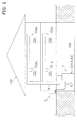
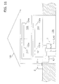
- FIG. 1 is a schematic diagram showing the arrangement of an air conditioning system 1 according to an embodiment of the present invention.
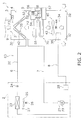
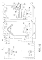
- FIG. 2 is a simplified schematic diagram of the air conditioning system 1.
- the air conditioning system 1 is an apparatus used to air-condition a residence or a building.
- the air conditioning system 1 in this embodiment is installed in a two-story residence 100.
- the residence 100 has rooms 101, 102 on the first floor and rooms 103, 104 on the second floor.
- the residence 100 also has a basement 105.
- the air conditioning system 1 is a so-called duct-type air conditioning system.
- the air conditioning system 1 has primarily an outdoor unit 2, a usage unit 3, refrigerant interconnection pipes 6, 7 connecting the outdoor unit 2 and the usage unit 3, and a duct 9 for sending air conditioned by the usage unit 3 to the rooms 101 to 104.
- the duct 9 is branched into the rooms 101 to 104 and is connected to ventilation ports 101a to 104a of the rooms 101 to 104.
- the outdoor unit 2, an indoor unit 4 which is part of the usage unit 3, and the refrigerant interconnection pipes 6, 7 configure a heat pump section 60 for performing indoor air-warming using by a vapor-compression refrigeration cycle.
- a gas furnace unit 5, which is part of the usage unit 3 configures a separate heat source section 70 for performing indoor air-warming using by a heat source (heat from gas combustion in this embodiment) separate from the heat pump section 60.
- the usage unit 3 has both the indoor unit 4 configuring the heat pump section 60 and the gas furnace unit 5 configuring the separate heat source section 70.
- the usage unit 3 also has an indoor air blower 40 for taking the air in the rooms 101 to 104 into a housing 30 of the usage unit 3, and supplying air conditioned by the heat pump section 60 (the indoor unit 4) and/or the separate heat source section 70 (the gas furnace unit 5) to the rooms 101 to 104.
- the usage unit 3 is also provided with a discharged air temperature sensor 33 for detecting a discharged air temperature Trd, which is the temperature of the air in an air outlet 31 of the housing 30, and an indoor temperature sensor 34 for detecting indoor temperature Tr, which is the temperature of the air in an air inlet 32 of the housing 30.
- the indoor temperature sensor 34 may be provided within the rooms 101 to 104 rather than in the usage unit 3.
- the heat pump section 60 is configured from the outdoor unit 2, the indoor unit 4 which is part of the usage unit 3, and the refrigerant interconnection pipes 6, 7.
- the outdoor unit 2 and the indoor unit 4 are connected via the refrigerant interconnection pipes 6, 7.
- a refrigerant circuit 20 is configured by the outdoor unit 2 and the indoor unit 4 being connected via the refrigerant interconnection pipes 6, 7.
- the refrigerant interconnection pipes 6, 7 are refrigerant pipes constructed on-site when the air conditioning system 1 is installed.
- the indoor unit 4 in this embodiment is provided inside the housing 30 of the usage unit 3 installed in the basement 105 of the residence 100.
- the indoor unit 4 has primarily an indoor heat exchanger 42 as a refrigerant heat-radiator for heating air by radiating the heat of the refrigerant in the refrigeration cycle.
- the indoor heat exchanger 42 is disposed on the farthest downwind side in the ventilation path from the air inlet 32 to the air outlet 31 formed in the housing 30 of the usage unit 3.
- the indoor unit 4 is also provided with an indoor heat exchange temperature sensor 35 for detecting the temperature Thx of refrigerant flowing through the indoor heat exchanger 42.
- the outdoor unit 2 is installed outside of the residence 100.
- the outdoor unit 2 which is connected to the indoor unit 4 via the refrigerant interconnection pipes 6, 7, configures part of the refrigerant circuit 20.
- the outdoor unit 2 has primarily a compressor 21, an outdoor heat exchanger 23, and an outdoor expansion valve 24.
- the compressor 21 is a hermetic compressor in which a compression element (not shown) and a compressor motor 22 for rotatably driving the compression element are accommodated within a casing.
- the compressor motor 22 is designed so that electric power is supplied via an inverter device (not shown), and the operating capacity can be varied by changing the frequency (i.e., the rotational speed) of the inverter device.
- the outdoor heat exchanger 23 is a heat exchanger that functions as a refrigerant evaporator which uses outdoor air to evaporate refrigerant in the refrigerant cycle.
- an outdoor fan 25 for sending outdoor air to the outdoor heat exchanger 23.
- the outdoor fan 25 is designed so as to be rotatably driven by an outdoor fan motor 26.
- the outdoor expansion valve 24 is a valve which depressurizes the refrigerant circulating through the refrigerant circuit 20, and adjusts the flow rate of refrigerant flowing through the indoor heat exchanger 42 as a refrigerant heat-radiator.
- the outdoor expansion valve 24 is an electric expansion valve connected to the liquid side of the outdoor heat exchanger 23.
- the outdoor unit 2 is also provided with an outdoor temperature sensor 27 for detecting the temperature of outdoor air outside of the residence 100 where the outdoor unit 2 is disposed, i.e., the outside air temperature Ta.
- the outdoor unit 2 also has an outdoor-side control unit 28 for controlling the actions of the components configuring the outdoor unit 2.
- the outdoor-side control unit 28, which has a microcomputer provided in order to control the outdoor unit 2, an inverter device which controls a memory and/or the compressor motor 22, and other components, is designed to be able to exchange control signals and the like with a usage-side control unit 38 of the usage unit 3.
- the separate heat source section 70 is configured from the gas furnace unit 5 which is part of the usage unit 3.
- the gas furnace unit 5 in this embodiment is provided within the housing 30 of the usage unit 3 disposed in the basement 105 of the residence 100.
- the gas furnace unit 5 is a gas combustion type air-warming apparatus, having primarily a fuel gas valve 51, a furnace fan 52, a combustion section 54, a furnace heat exchanger 55, an air-feeding pipe 56, and an exhaust pipe 57.
- the fuel gas valve 51 composed of an electromagnetic valve or the like of which the opening and closing can be controlled, is provided to a fuel gas supply pipe 58 extending to the combustion section 54 from outside of the housing 30.
- natural gas, petroleum gas, or the like is used as the fuel gas.
- the furnace fan 52 is a fan which takes air into the combustion section 54 through the air-feeding pipe 56, then sends the air to the furnace heat exchanger 55, and creates an air flow which is discharged from the exhaust pipe 57.
- the furnace fan 52 is designed so as to be rotatably driven by a furnace fan motor 53.
- the combustion section 54 is a device which obtains high-temperature combustion gas, by combustion of a mixed gas of fuel gas and air by using a gas burner or the like (not shown).
- the furnace heat exchanger 55 which is a heat exchanger for heating air by radiating the heat of the combustion gas obtained by the combustion section 54, functions as a separate heat source heat-radiator for heating air by radiating the heat of a heat source (heat from gas combustion in this embodiment) that is separate from the heat pump section 60.
- the furnace heat exchanger 55 is disposed within the ventilation path from the air inlet 32 to the air outlet 31 formed in the housing 30 of the usage unit 3, on the side upwind from the indoor heat exchanger 42 as a refrigerant heat-radiator.
- the indoor air blower 40 is an air blower for supplying the rooms 101 to 104 with air heated by the indoor heat exchanger 42 as a refrigerant heat-radiator configuring the heat pump section 60, and/or by the furnace heat exchanger 55 as a separate heat source heat-radiator configuring the separate heat source section 70.
- the indoor air blower 40 is disposed within the ventilation path from the air inlet 32 to the air outlet 31 formed in the housing 30 of the usage unit 3, on the side upwind from both the indoor heat exchanger 42 and the furnace heat exchanger 55.
- the indoor air blower 40 has an indoor fan 43 and an indoor fan motor 44 for rotatably driving the indoor fan 43.
- the usage unit 3 has the usage-side control unit 38 for controlling the actions of the components (the indoor unit 4, the gas furnace unit 5, and the indoor air blower 40) configuring the usage unit 3.
- the usage-side control unit 38 has a microcomputer, a memory, and other components provided in order to control the usage unit 3, and this control unit is designed to be able to exchange control signals and the like with the outdoor unit 2.
- the usage-side control unit 38 of the usage unit 3 and the outdoor-side control unit 28 of the outdoor unit 2 configure a control unit 8 for performing operation control on the entire air conditioning system 1, as shown in FIG. 2 .
- the control unit 8 is connected so as to be able to receive detection signals from the various sensors 27, 33, 34, 35, etc., as shown in FIG. 3 .
- the control unit 8 is configured so as to perform an air-conditioning operation (an air-warming operation) by controlling the various devices and valves 22, 24, 26, 44, 51, 53, i.e., by controlling the actions of the heat pump section 60 and the separate heat source section 70, on the basis of these detection signals and the like.
- the control unit 8 performs control so that the indoor temperature Tr in the rooms 101 to 104 reaches a target indoor temperature Trs, while switching as appropriate between a heat pump air-warming operation in which air-warming in the rooms 101 to 104 is performed by the heat pump section 60, and a separate heat source air-warming operation in which air-warming in the rooms 101 to 104 is performed by the separate heat source section 70.
- FIG. 3 in this case is a control block diagram of the air conditioning system 1.
- FIGS. 1 to 3 are used to describe the basic actions of the air-conditioning operation (the air-warming operation) of the air conditioning system 1.
- the air-warming operation of the air conditioning system 1 includes a heat pump air-warming operation in which indoor air-warming is performed by the heat pump section 60, and a separate heat source air-warming operation in which indoor air-warming is performed by the separate heat source section 70, as described above.
- the refrigerant in the refrigerant circuit 20 is drawn into the compressor 21 and compressed to a high-pressure gas refrigerant.
- This high-pressure gas refrigerant is sent from the outdoor unit 2 to the indoor unit 4 of the usage unit 3, via the gas refrigerant interconnection pipe 7.
- the high-pressure gas refrigerant sent to the indoor unit 4 of the usage unit 3 is sent to the indoor heat exchanger 42 as a refrigerant heat-radiator.
- the high-pressure gas refrigerant sent to the indoor heat exchanger 42 is condensed to a high-pressure liquid refrigerant in the indoor heat exchanger 42 by being cooled by heat exchange with indoor air F1 (F2) supplied by the indoor air blower 40.
- This high-pressure liquid refrigerant is sent from the indoor unit 4 of the usage unit 3 to the outdoor unit 2, via the liquid refrigerant interconnection pipe 6.
- Indoor air F3 heated in the indoor heat exchanger 42 is sent from the usage unit 3 through the duct 9 to the rooms 101 to 104, and air-warming is performed.
- the high-pressure liquid refrigerant sent to the outdoor unit 2 is sent to the outdoor expansion valve 24 and is depressurized by the outdoor expansion valve 24 to a low-pressure gas-liquid two-phase refrigerant.
- This low-pressure gas-liquid two-phase refrigerant is sent to the outdoor heat exchanger 23 as a refrigerant evaporator.
- the low-pressure gas-liquid two-phase refrigerant sent to the outdoor heat exchanger 23 is evaporated to a low-pressure gas refrigerant in the outdoor heat exchanger 23 by being heated by heat exchange with outdoor air supplied by the outdoor fan 25. This low-pressure gas refrigerant is again drawn into the compressor 21.
- the control unit 8 performs control so that the indoor temperature Tr in the rooms 101 to 104 reaches the target indoor temperature Trs, either by controlling the operating capacity Gr of the compressor 21 or by controlling the opening degree MV of the outdoor expansion valve 24. Specifically, when a temperature difference ⁇ Tr, which is resulting from subtracting the target indoor temperature Trs from the indoor temperature Tr, is large, the operating capacity Gr of the compressor 21 (e.g., the rotational speed of the compressor motor 22) is increased and the opening degree MV of the outdoor expansion valve 24 is increased.
- a temperature difference ⁇ Tr which is resulting from subtracting the target indoor temperature Trs from the indoor temperature Tr
- control unit 8 performs control which increases the operating capacity Gr of the compressor 21 and increases the opening degree MV of the outdoor expansion valve 24 when the temperature difference ⁇ Tr, which is resulting from subtracting the target indoor temperature Trs from the indoor temperature Tr, is large, and reduces the operating capacity Gr of the compressor 21 and reduces the opening degree MV of the outdoor expansion valve 24 when the temperature difference ⁇ Tr is small.
- fuel gas is supplied to the combustion section 54 by opening the fuel gas valve 51, the fuel gas in the combustion section 54 mixes with air taken into the gas furnace unit 5 of the usage unit 3 via the air-feeding pipe 56 by the furnace fan 52, the fuel gas ignites and thereby combusts, and a high-temperature combustion gas is produced.
- the high-temperature combustion gas produced in the combustion section 54 is sent to the furnace heat exchanger 55 as a separate heat source heat-radiator.
- the high-temperature combustion gas sent to the furnace heat exchanger 55 is cooled to a low-temperature combustion gas in the furnace heat exchanger 55 by heat exchange with the indoor air F1 supplied by the indoor air blower 40.
- This low-temperature combustion gas is discharged from the gas furnace unit 5 of the usage unit 3 via the exhaust pipe 57.
- the indoor air F2 (F3) heated in the furnace heat exchanger 55 is sent from the usage unit 3 through the duct 9 to the rooms 101 to 104, and air-warming is performed.
- the control unit 8 performs control so that the indoor temperature Tr in the rooms 101 to 104 reaches the target indoor temperature Trs, by controlling the opening and closing of the fuel gas valve 51. Specifically, the control unit 8 performs control which opens the fuel gas valve 51 when the temperature difference ⁇ Tr, which is resulting from subtracting the target indoor temperature Trs from the indoor temperature Tr, increases, and closes the fuel gas valve 51 when the temperature difference ⁇ Tr decreases.
- the air-conditioning load (the air-warming load) in the rooms (the rooms 101 to 104 in this embodiment) cannot be covered by the heat pump air-warming operation when the outside air temperature Ta is extremely low, and it is therefore necessary to perform the actions to switch the heat pump air-warming operation to the separate heat source air-warming operation as the outside air temperature Ta falls, and to switch the separate heat source air-warming operation to the heat pump air-warming operation as the outside air temperature Ta rises.
- the basic switching action is that when the heat pump air-warming operation is being performed and a first switching condition is met which is that the outside air temperature Ta reaches a first switching outside air temperature Tas1, the operation is switched from the heat pump air-warming operation to the separate heat source air-warming operation, and when the separate heat source air-warming operation is being performed and a second switching condition is met which is that the outside air temperature Ta reaches a second switching outside air temperature Tas2, the operation is switched from the separate heat source air-warming operation to the heat pump air-warming operation.
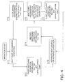
- FIG. 4 is a flowchart showing the action of switching between the heat pump air-warming operation and the separate heat source air-warming operation.
- the action of switching between the heat pump air-warming operation and the separate heat source air-warming operation is performed by the control unit 8.
- the heat pump air-warming operation of step ST1 is performed.
- a determination is made as to whether or not the first switching condition of step ST2 is met.
- This first switching condition is a condition for determining whether or not to switch from the heat pump air-warming operation to the separate heat source air-warming operation.
- another part of the determination condition is that the air-warming capability of the heat pump section 60 has reached an upper limit, in order to ensure that the level of comfort and energy conservation can be improved with an appropriate switching timing.
- the first switching condition is that the outside air temperature Ta reaches the first switching outside air temperature Tas1 and the air-warming capability of the heat pump section 60 reaches the upper limit. Whether or not the air-warming capability of the heat pump section 60 has reached the upper limit is determined on the basis of the indoor temperature Tr and/or the operating capacity of the devices (the compressor 21 and/or the outdoor expansion valve 24 in this case) configuring the heat pump section 60.
- the first switching condition may also be solely a condition of the outside air temperature Ta.
- step ST2 When it is determined in step ST2 that the first switching condition is met, the sequence transitions to the process of step ST3, i.e., the operation switches from the heat pump air-warming operation to the separate heat source air-warming operation.
- step ST2 When it is determined in step ST2 that the first switching condition is not met, the heat pump air-warming operation of step ST1 is continued.
- This second switching condition is a condition for determining whether or not to switch from the separate heat source air-warming operation to the heat pump air-warming operation.
- the condition is that the outside air temperature Ta during the separate heat source air-warming operation is equal to or greater than the second switching outside air temperature Tas2.
- step ST4 When it is determined in step ST4 that the second switching condition is met, the sequence transitions to the process of ST1, i.e., the operation switches from the separate heat source air-warming operation to the heat pump air-warming operation, via the action of starting the heat pump air-warming operation while the separate heat source air-warming operation is continued (steps ST5, ST6) as described hereinafter.
- step ST4 When it is determined in step ST4 that the second switching condition is not met, the separate heat source air-warming operation of step ST3 is continued.
- the heat pump air-warming operation is started while the separate heat source air-warming operation is continued, and the separate heat source air-warming operation is ended after an overlapping air-warming ending condition has been met.
- step ST4 when it is determined in step ST4 that the second switching condition is met, the sequence transitions to the process of step ST5, and the heat pump air-warming operation is started while the separate heat source air-warming operation is continued. It is thereby possible for the separate heat source section 70 to support the air-warming capability deficiency when the heat pump air-warming operation is starting up.
- step ST5 a determination is made as to whether or not the overlapping air-warming ending condition of step ST6 is met, as is a determination as to whether or not the first switching condition of step ST7 is met.
- step ST7 of whether or not the first switching condition is met is the same determination content as the determination in step ST2 of whether or not the first switching condition is met, and when it is determined that the first switching condition is met during the heat pump air-warming operation accompanying the separate heat source air-warming operation of step ST5, the sequence transitions to the process of step ST3, i.e., operation does not transition to the heat pump air-warming operation of step ST1 but returns to the separate heat source air-warming operation, and a determination is again made as to whether or not the second switching condition of step ST4 is met.
- the overlapping air-warming ending condition of step ST6 is a condition for determining whether or not to end the separate heat source air-warming operation, i.e., whether or not the heat pump air-warming operation has taken effect.
- the overlapping air-warming ending condition is that the temperature Trd of the air that has been heated by the indoor heat exchanger 42 as a refrigerant heat-radiator is equal to or greater than an overlapping air-warming ending air temperature Trds1.
- step ST6 When it is determined in step ST6 that the overlapping air-warming ending condition is met, the sequence transitions to the process of step ST1, i.e., to the heat pump air-warming operation.
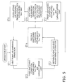
- the overlapping air-warming ending condition of step ST6 in the above embodiment is not limited to the condition of the above embodiment.
- control unit 8 may determine if the air-warming capability Qa is equal to or greater than an overlapping air-warming ending capability Qas1 as the overlapping air-warming ending condition in step ST6, as shown in FIG. 5 , the air-warming capability Qa being resulted from subtracting the air-warming capability Qg of the separate heat source section 70 from an air-warming capability Qt, which is calculated from the temperature Trd of the air heated by both the indoor heat exchanger 42 as a refrigerant heat-radiator and the furnace heat exchanger 55 as a separate heat source heat-radiator, and from the flow rate Ga of air supplied into the rooms by the indoor air blower 40.
- the heat exchange quantity in both the indoor heat exchanger 42 and the furnace heat exchanger 55 (i.e., the total air-warming capability Qt of the heat pump section 60 and the separate heat source section 70) is calculated by subtracting the indoor air temperature Tr, which is the temperature before the air is heated by both the indoor heat exchanger 42 as a refrigerant heat-radiator and the furnace heat exchanger 55 as a separate heat source heat-radiator, from the air temperature Trd, which is the temperature after the air has been heated by both the indoor heat exchanger 42 as a refrigerant heat-radiator and the furnace heat exchanger 55 as a separate heat source heat-radiator, and multiplying the resulting temperature difference by the indoor air flow rate Ga calculated from parameters such as the rotational speed of the indoor fan motor 44 of the indoor air blower 40.
- the air-warming capability Qa of the heat pump section 60 is calculated and it is determined whether or not this air-warming capability Qa is equal to or greater than the overlapping air-warming ending capability Qas1.
- the overlapping air-warming ending condition of step ST6 in the above embodiment is not limited to the conditions of the above embodiment or modification thereof.
- control unit 8 stores the temperature Trdm of air that has been heated by the furnace heat exchanger 55 as a separate heat source heat-radiator as shown in FIG. 6 , and from this air temperature Trdm estimates the rise ⁇ Tg in air temperature caused by the air-warming capability Qg of the separate heat source section 70.
- this air temperature rise ⁇ Tg is taken into account to decide an overlapping air-warming ending air temperature Trds2, and the overlapping air-warming ending condition may be that the air temperature Trd, which is the temperature of the air heated by both the indoor heat exchanger 42 as a refrigerant heat-radiator and the furnace heat exchanger 55 as a separate heat source heat-radiator, is equal to or greater than this overlapping air-warming ending air temperature Trds2.
- whether or not the heat pump air-warming operation has taken effect is determined on the basis of the temperature Trd of the air heated by both the indoor heat exchanger 42 as a refrigerant heat-radiator and the furnace heat exchanger 55 as a separate heat source heat-radiator. More specifically, whether or not the heat pump air-warming operation has taken effect is determined on the basis of the temperature Trdm of air that has been heated by the furnace heat exchanger 55 as a separate heat source heat-radiator when the separate heat source air-warming operation is performed, and also on the basis of the temperature Trd of the air heated by both the indoor heat exchanger 42 as a refrigerant heat-radiator and the furnace heat exchanger 55 as a separate heat source heat-radiator. It is possible with this determination method as well to appropriately determine whether or not the heat pump air-warming operation has taken effect, and to switch from the separate heat source air-warming operation to the heat pump air-warming operation.
- the overlapping air-warming ending condition of step ST6 in the above embodiment is not limited to the conditions of the above embodiment or the modifications thereof.
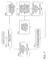
- the control unit 8 may determine if the temperature difference ⁇ Tr, which is resulted from subtracting the target indoor temperature Trs from the indoor temperature Tr, is equal to or greater than an overlapping air-warming ending air temperature difference ⁇ Trs1, as shown in FIG. 7 .
- This overlapping air-warming ending condition based on the temperature difference ⁇ Tr may be used together with the overlapping air-warming ending condition based on the temperature Trd of the air heated by the indoor heat exchanger 42 as a refrigerant heat-radiator configuring the heat pump section 60, the air-warming capability Qa of the heat pump section 60, or the temperature Trd of the air heated by both the indoor heat exchanger 42 as a refrigerant heat-radiator and the furnace heat exchanger 55 as a separate heat source heat-radiator, in the above embodiment and the Modifications A and B thereof.
- the configuration employed as the air conditioning system 1 is one in which air heated by the furnace heat exchanger 55 as a separate heat source heat-radiator configuring the separate heat source section 70 is further heated by the indoor heat exchanger 42 as a refrigerant heat-radiator configuring the heat pump section 60, after which the air is supplied into the rooms.
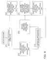
- the control unit 8 determines if the temperature Thx of the refrigerant flowing through the indoor heat exchanger 42 as a refrigerant heat-radiator is equal to or greater than an overlapping air-warming ending heat exchange temperature Thxs1, as shown in FIG. 8.
- FIG. 8 shows an example in which this condition is used together with the overlapping air-warming ending condition based on the temperature Trd of the air heated by the indoor heat exchanger 42 as a refrigerant heat-radiator configuring the heat pump section 60 in the above embodiment, but this condition may also be used together with the overlapping air-warming ending conditions of Modifications A to C.
- the heat pump section 60 can be protected on the basis of the temperature Thx of the refrigerant flowing through the indoor heat exchanger 42 as a refrigerant heat-radiator.
- the overlapping air-warming ending condition of step ST6 in the above embodiment is not limited to the conditions of the above embodiment or the modifications thereof.
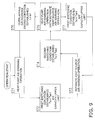
- the control unit 8 may determine if the time t from when the heat pump air-warming operation was started while the separate heat source air-warming operation was continued has reached an overlapping air-warming ending time ts1, as shown in FIG. 9 . It is possible with this determination method as well to appropriately determine whether or not the heat pump air-warming operation has taken effect, and to switch from the separate heat source air-warming operation to the heat pump air-warming operation.
- the overlapping air-warming ending condition based on the time t from when the heat pump air-warming operation was started while the separate heat source air-warming operation was continued may be used together with the overlapping air-warming ending condition based on the temperature Trd of the air heated by the indoor heat exchanger 42 as a refrigerant heat-radiator configuring the heat pump section 60, the air-warming capability Qa of the heat pump section 60, the temperature Trd of the air heated by both the indoor heat exchanger 42 as a refrigerant heat-radiator and the furnace heat exchanger 55 as a separate heat source heat-radiator, and/or the temperature Thx of the indoor heat exchanger 42 as a refrigerant heat-radiator configuring the heat pump section 60 in the above embodiment and the Modifications A to D thereof.
- the gas furnace unit 5 configuring the separate heat source section 70 i.e., the furnace heat exchanger 55 as a separate heat source heat-radiator
- the heat pump section 60 i.e., the indoor heat exchanger 42 as a refrigerant heat-radiator
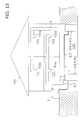
- the gas furnace unit 5 as the separate heat source section 70 may be disposed on the downwind side of the indoor unit 4 as the heat pump section 60 (i.e., the indoor heat exchanger 42 as a refrigerant heat-radiator), as shown in FIG. 10 .
- step ST6 when an overlapping air-warming ending condition is employed which is based on the temperature Trd of the air heated by the indoor heat exchanger 42 as a refrigerant heat-radiator configuring the heat pump section 60, a temperature sensor 36 must be provided between the indoor heat exchanger 42 as a refrigerant heat-radiator and the furnace heat exchanger 55 as a separate heat source heat-radiator.
- the gas furnace unit 5 configuring the separate heat source section 70 and the indoor unit 4 configuring the heat pump section 60 are configured as an integrated usage unit 3, but the present invention is not limited to this arrangement.
- the gas furnace unit 5 configuring the separate heat source section 70 and the indoor unit 4 configuring the heat pump section 60 may be arranged separately as shown in FIGS. 11 and 12 .
- the indoor air blower 40 and other various devices and/or sensors that had been shared between the gas furnace unit 5 and the indoor unit 4 in the above embodiment and the modifications thereof must be provided to both the gas furnace unit 5 and the indoor unit 4.
- a single usage unit 3 (indoor unit 4) is connected to the outdoor unit 2, but the present invention is not limited to this arrangement.
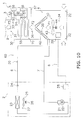
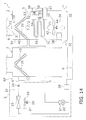
- a plurality (two in this modification) of usage units 3 may be connected to the outdoor unit 2 via the refrigerant interconnection pipes 6, 7, one usage unit 3 may be used to air-condition the rooms 103, 104, and the other usage unit 3 may be used to air-condition the rooms 101, 102, as shown in FIGS. 13 and 14 .
- FIG. 14 the details of one usage unit 3 are illustrated, and for the other usage unit 3, only the indoor heat exchanger 42 as a refrigerant heat-radiator configuring the heat pump section 60 is illustrated.
- the corresponding usage units 3 When a configuration is employed in which a plurality of usage units 3 are connected to the outdoor unit 2, rather than being provided in the basement 105, the corresponding usage units 3 may be provided in the rooms they are used to air-condition or in proximity thereto.
- usage units 3 corresponding to the rooms 101 to 104 are provided, rather than being duct-type units, the usage units 3 may be installed as being placed on the floors, mounted on the walls, installed on the ceilings, or the like of the rooms 101 to 104.
- gas furnace units 5 configuring separate heat source sections 70 and indoor units 4 configuring heat pump sections 60 may be placed separately for the different rooms, similar to Modification E.
- the heat pump section 60 has a refrigerant circuit 20 solely for air-warming, but a four-way switching valve or the like may be provided to the refrigerant circuit 20 to enable switching the refrigerant circulation direction, and the configuration may be enabled for an air-cooling operation.
- a gas furnace unit 5 which uses the combustion of fuel gas as a heat source is employed as the separate heat source section 70, but the present invention is not limited to this arrangement.
- the present invention is widely applicable to an air conditioning system that has a heat pump section for performing indoor air-warming by using a vapor-compression refrigeration cycle, and a separate heat source section for performing indoor air-warming by using a heat source separate from the heat pump section.
Abstract
Description
- The present invention relates to an air conditioning system, and particularly relates to an air conditioning system having a heat pump section for performing indoor air-warming by using a vapor-compression refrigeration cycle, and a separate heat source section for performing indoor air-warming by using a heat source separate from the heat pump section.
- In the past, there have been air conditioning systems which have a heat pump section for performing indoor air-warming by using a vapor-compression refrigeration cycle, and a separate heat source section for performing indoor air-warming by using a gas furnace which is a heat source separate from the heat pump section. An example of such an air conditioning system is one in which an air-warming operation by the heat pump section (referred to below as the "heat pump air-warming operation") is switched to an air-warming operation by the separate heat source section (referred to below as the "separate heat source air-warming operation") as an outside air temperature drops, and the separate heat source air-warming operation is switched to the heat pump air-warming operation as the outside air temperature rises, as is indicated in Patent Literature 1 (Japanese Laid-open Patent Application No.
64-54160 - With the method of switching from the separate heat source air-warming operation to the heat pump air-warming operation in the
aforementioned Patent Literature 1, there is a risk of an indoor temperature temporarily dropping and the a comfort level being impaired because the heat pump air-warming operation takes time to take effect. - An object of the present invention is to suppress the temporary drop in the indoor temperature and the impairment of the comfort level when the operation is switched from the separate heat source air-warming operation to the heat pump air-warming operation in the air conditioning system comprising the heat pump section and the separate heat source section.
- An air conditioning system according to a first aspect has a heat pump section for performing indoor air-warming by using a vapor-compression refrigeration cycle, a separate heat source section for performing indoor air-warming by using a heat source separate from the heat pump section, and a control unit for controlling actions of the heat pump section and the separate heat source section. In this aspect, when an operation is switched from a separate heat source air-warming operation for performing indoor air-warming by using the separate heat source section to a heat pump air-warming operation for performing indoor air-warming by using the heat pump section, the control unit starts the heat pump air-warming operation while the separate heat source air-warming operation is continued, and after an overlapping air-warming ending condition is met, the control unit ends the separate heat source air-warming operation.
- In this aspect, when the operation switches from the separate heat source air-warming operation to the heat pump air-warming operation as described above, it is possible for the separate heat source section to support the air-warming capability deficiency when the heat pump air-warming operation is starting up.
- It is thereby possible in this aspect to suppress the temporary drop in indoor temperature and the impairment of the comfort level when the operation switches from the separate heat source air-warming operation to the heat pump air-warming operation.
- An air conditioning system according to a second aspect is the air conditioning system according to the first aspect, wherein the heat pump section has a refrigerant heat-radiator for heating an air by radiating a heat of a refrigerant in the refrigeration cycle. The overlapping air-warming ending condition is that a temperature of the air heated by the refrigerant heat-radiator is equal to or greater than an overlapping air-warming ending air temperature.
- In the air conditioning system comprising the heat pump section and the separate heat source section, when the heat pump air-warming operation is started while the separate heat source air-warming operation is continued, if the temperature of the air heated by the refrigerant heat-radiator configuring the heat pump section has sufficiently risen, it can be presumed that the air-warming capability of the heat pump section is great enough, i.e., that the heat pump air-warming operation has taken effect.
- In view of this, in this aspect, whether or not the heat pump air-warming operation has taken effect is determined on the basis of the temperature of air heated by the refrigerant heat-radiator configuring the heat pump section, as described above.
- It is thereby possible in this aspect to appropriately determine whether or not the heat pump air-warming operation has taken effect, and to switch from the separate heat source air-warming operation to the heat pump air-warming operation.
- An air conditioning system according to a third aspect is the air conditioning system according to the first aspect, wherein the heat pump section has a refrigerant heat-radiator for heating an air by radiating a heat of a refrigerant in the refrigeration cycle, and the separate heat source section has a separate heat source heat-radiator for heating the air by radiating a heat of a heat source separate from the heat pump section. The air conditioning system further has an indoor air blower for supplying a room with the air heated by both the refrigerant heat-radiator and the separate heat source heat-radiator. The overlapping air-warming ending condition is that an air-warming capability resulting from subtracting an air-warming capability of the separate heat source section from an air-warming capability calculated from a temperature of the air heated by both the refrigerant heat-radiator and the separate heat source heat-radiator and from a flow rate of the air supplied into the room by the indoor air blower is equal to or greater than an overlapping air-warming ending capability.
- In this aspect, the air conditioning system employs a configuration in which the room is supplied with the air heated by both the refrigerant heat-radiator configuring the heat pump section and the separate heat source heat-radiator configuring the separate heat source section, as described above. Therefore, when the heat pump air-warming operation is started while the separate heat source air-warming operation is continued, there are cases in which the air-warming capability of the heat pump section is essentially not great enough merely with the air temperature being increased by the air-warming capability of the separate heat source section.
- In view of this, in this aspect, whether or not the heat pump air-warming operation has taken effect is determined on the basis of the air-warming capability resulting from subtracting the air-warming capability of the separate heat source section from the air-warming capability calculated from the temperature of the air heated by both the refrigerant heat-radiator and the separate heat source heat-radiator and the flow rate of the air supplied into the room by the indoor air blower, i.e., on the basis of the air-warming capability of the heat pump section.
- It is thereby possible in this aspect to appropriately determine whether or not the heat pump air-warming operation has taken effect, and to switch from the separate heat source air-warming operation to the heat pump air-warming operation.
- An air conditioning system according to a fourth aspect is the air conditioning system according to the first aspect, wherein the heat pump section has a refrigerant heat-radiator for heating an air by radiating a heat of a refrigerant in the refrigeration cycle, and the separate heat source section has a separate heat source heat-radiator for heating the air by radiating a heat of a heat source separate from the heat pump section. The overlapping air-warming ending condition is that a temperature of the air heated by both the refrigerant heat-radiator and the separate heat source heat-radiator is equal to or greater than an overlapping air-warming ending air temperature.
- In this aspect, the air conditioning system employs a configuration in which the room is supplied with the air heated by both the refrigerant heat-radiator configuring the heat pump section and the separate heat source heat-radiator configuring the separate heat source section, as described above. Therefore, when the heat pump air-warming operation is started while the separate heat source air-warming operation is continued, there are cases in which the air-warming capability of the heat pump section is essentially not great enough merely with the air temperature being increased by the air-warming capability of the separate heat source section. The rise in the air temperature from the air-warming capability of the separate heat source section can be estimated from the temperature of the air heated by the separate heat source heat-radiator when the separate heat source air-warming operation is performed. Therefore, if it is possible to know the temperature of the air heated by both the refrigerant heat-radiator and the separate heat source heat-radiator, it is also possible to estimate the rise in the air temperature caused by the heat pump air-warming operation.
- In view of this, in this aspect, whether or not the heat pump air-warming operation has taken effect is determined on the basis of the temperature of the air heated by both the refrigerant heat-radiator and the separate heat source heat-radiator, as described above.
- It is thereby possible in this aspect to appropriately determine whether or not the heat pump air-warming operation has taken effect, and to switch from the separate heat source air-warming operation to the heat pump air-warming operation.
- An air conditioning system according to a fifth aspect is the air conditioning system according to the first aspect, wherein the overlapping air-warming ending condition is that a temperature difference resulting from subtracting a target indoor temperature from an indoor temperature is equal to or greater than an overlapping air-warming ending air temperature difference.
- In the air conditioning system including the heat pump section and the separate heat source section, when the heat pump air-warming operation is started while the separate heat source air-warming operation is continued and the temperature difference resulting from subtracting the target indoor temperature from the indoor temperature is great enough, the total air-warming capability combining the air-warming capability of the heat pump section and the air-warming capability of the separate heat source section is great enough, and it can therefore be presumed that the air-warming capability of the heat pump section is great enough, i.e., that the heat pump air-warming operation has taken effect.
- In view of this, in this aspect, whether or not the heat pump air-warming operation has taken effect is determined on the basis of the temperature difference resulting from subtracting the target indoor temperature from the indoor temperature.
- It is thereby possible in this aspect to appropriately determine whether or not the heat pump air-warming operation has taken effect, and to switch from the separate heat source air-warming operation to the heat pump air-warming operation.
- An air conditioning system according to a sixth aspect is the air conditioning system according to the first aspect, wherein the heat pump section has a refrigerant heat-radiator for heating an air by radiating a heat of a refrigerant in the refrigeration cycle, and the separate heat source section has a separate heat source heat-radiator for heating the air by radiating a heat of a heat source separate from the heat pump section. The air conditioning system further has an indoor air blower for supplying a room with the air heated by both the refrigerant heat-radiator and the separate heat source heat-radiator. The separate heat source heat-radiator is disposed on a side upwind from the refrigerant heat-radiator. The overlapping air-warming ending condition is that a temperature of the refrigerant flowing through the refrigerant heat-radiator is equal to or greater than an overlapping air-warming ending heat exchange temperature.
- In this aspect, the air conditioning system employs the configuration in which the air heated by the separate heat source heat-radiator configuring the separate heat source section is further heated by the refrigerant heat-radiator configuring the heat pump section, and the air is then supplied into the room, as described above. Therefore, when the heat pump air-warming operation is started while the separate heat source air-warming operation is continued, there are cases in which the temperature of the air heated by the separate heat source heat-radiator is too high, whereby the temperature of the refrigerant heat-radiator configuring the heat pump section, and consequently the refrigeration cycle of the heat pump section, shifts towards too high temperature and too high pressure, and the heat pump section must be protected.
- In view of this, in this aspect, the heat pump section is protected on the basis of the temperature of the refrigerant flowing through the refrigerant heat-radiator, as described above.
- It is thereby possible in this aspect to suppress the temporary drop in the indoor temperature and the impairment of the comfort level, while protecting the heat pump section, when the operation switches from the separate heat source air-warming operation to the heat pump air-warming operation.
-
-
FIG. 1 is a schematic diagram showing the arrangement of an air conditioning system according to an embodiment of the present invention. -
FIG. 2 is a simplified configuration diagram of the air conditioning system. -
FIG. 3 is a control block diagram of the air conditioning system. -
FIG. 4 is a flowchart showing actions of switching between a heat pump air-warming operation and a separate heat source air-warming operation. -
FIG. 5 is a flowchart showing the actions of switching between the heat pump air-warming operation and the separate heat source air-warming operation, according to Modification <A>. -
FIG. 6 is a flowchart showing the actions of switching between the heat pump air-warming operation and the separate heat source air-warming operation, according to Modification <B>. -
FIG. 7 is a flowchart showing the actions of switching between the heat pump air-warming operation and the separate heat source air-warming operation, according to Modification <C>. -
FIG. 8 is a flowchart showing the actions of switching between the heat pump air-warming operation and the separate heat source air-warming operation, according to Modification <D>. -
FIG. 9 is a flowchart showing the actions of switching between the heat pump air-warming operation and the separate heat source air-warming operation, according to Modification <E>. -
FIG. 10 is a simplified configuration diagram of the air conditioning system according to Modification <F>. -
FIG. 11 is a schematic diagram showing the arrangement of the air conditioning system according to Modification <G>. -
FIG. 12 is a simplified configuration diagram of the air conditioning system according to Modification <G>. -
FIG. 13 is a schematic diagram showing the arrangement of the air conditioning system according to Modification <H>. -
FIG. 14 is a simplified configuration diagram of the air conditioning system according to Modification <H>. - An embodiment of an air conditioning system according to the present invention is described below on the basis of the drawings. The specific configuration of the embodiment of the air conditioning system according to the present invention is not limited to the following embodiment or the modifications thereof, and the configuration can be altered within a range that does not deviate from the scope of the invention.
-
FIG. 1 is a schematic diagram showing the arrangement of anair conditioning system 1 according to an embodiment of the present invention.FIG. 2 is a simplified schematic diagram of theair conditioning system 1. Theair conditioning system 1 is an apparatus used to air-condition a residence or a building. Theair conditioning system 1 in this embodiment is installed in a two-story residence 100. Theresidence 100 hasrooms rooms residence 100 also has abasement 105. - The
air conditioning system 1 is a so-called duct-type air conditioning system. Theair conditioning system 1 has primarily an outdoor unit 2, ausage unit 3,refrigerant interconnection pipes usage unit 3, and aduct 9 for sending air conditioned by theusage unit 3 to therooms 101 to 104. Theduct 9 is branched into therooms 101 to 104 and is connected toventilation ports 101a to 104a of therooms 101 to 104. - In this embodiment, the outdoor unit 2, an
indoor unit 4 which is part of theusage unit 3, and therefrigerant interconnection pipes heat pump section 60 for performing indoor air-warming using by a vapor-compression refrigeration cycle. Agas furnace unit 5, which is part of theusage unit 3, configures a separateheat source section 70 for performing indoor air-warming using by a heat source (heat from gas combustion in this embodiment) separate from theheat pump section 60. Thus, in this embodiment, theusage unit 3 has both theindoor unit 4 configuring theheat pump section 60 and thegas furnace unit 5 configuring the separateheat source section 70. Theusage unit 3 also has anindoor air blower 40 for taking the air in therooms 101 to 104 into ahousing 30 of theusage unit 3, and supplying air conditioned by the heat pump section 60 (the indoor unit 4) and/or the separate heat source section 70 (the gas furnace unit 5) to therooms 101 to 104. Theusage unit 3 is also provided with a dischargedair temperature sensor 33 for detecting a discharged air temperature Trd, which is the temperature of the air in anair outlet 31 of thehousing 30, and anindoor temperature sensor 34 for detecting indoor temperature Tr, which is the temperature of the air in anair inlet 32 of thehousing 30. Theindoor temperature sensor 34 may be provided within therooms 101 to 104 rather than in theusage unit 3. - The
heat pump section 60, as described above, is configured from the outdoor unit 2, theindoor unit 4 which is part of theusage unit 3, and therefrigerant interconnection pipes indoor unit 4 are connected via therefrigerant interconnection pipes heat pump section 60, arefrigerant circuit 20 is configured by the outdoor unit 2 and theindoor unit 4 being connected via therefrigerant interconnection pipes refrigerant interconnection pipes air conditioning system 1 is installed. - The
indoor unit 4 in this embodiment is provided inside thehousing 30 of theusage unit 3 installed in thebasement 105 of theresidence 100. Theindoor unit 4, which is connected to the outdoor unit 2 via therefrigerant interconnection pipes refrigerant circuit 20. Theindoor unit 4 has primarily anindoor heat exchanger 42 as a refrigerant heat-radiator for heating air by radiating the heat of the refrigerant in the refrigeration cycle. In this embodiment, theindoor heat exchanger 42 is disposed on the farthest downwind side in the ventilation path from theair inlet 32 to theair outlet 31 formed in thehousing 30 of theusage unit 3. Theindoor unit 4 is also provided with an indoor heatexchange temperature sensor 35 for detecting the temperature Thx of refrigerant flowing through theindoor heat exchanger 42. - The outdoor unit 2 is installed outside of the
residence 100. The outdoor unit 2, which is connected to theindoor unit 4 via therefrigerant interconnection pipes refrigerant circuit 20. The outdoor unit 2 has primarily acompressor 21, anoutdoor heat exchanger 23, and anoutdoor expansion valve 24. Thecompressor 21 is a hermetic compressor in which a compression element (not shown) and acompressor motor 22 for rotatably driving the compression element are accommodated within a casing. Thecompressor motor 22 is designed so that electric power is supplied via an inverter device (not shown), and the operating capacity can be varied by changing the frequency (i.e., the rotational speed) of the inverter device. Theoutdoor heat exchanger 23 is a heat exchanger that functions as a refrigerant evaporator which uses outdoor air to evaporate refrigerant in the refrigerant cycle. Provided in proximity to theoutdoor heat exchanger 23 is anoutdoor fan 25 for sending outdoor air to theoutdoor heat exchanger 23. Theoutdoor fan 25 is designed so as to be rotatably driven by anoutdoor fan motor 26. Theoutdoor expansion valve 24 is a valve which depressurizes the refrigerant circulating through therefrigerant circuit 20, and adjusts the flow rate of refrigerant flowing through theindoor heat exchanger 42 as a refrigerant heat-radiator. In this embodiment, theoutdoor expansion valve 24 is an electric expansion valve connected to the liquid side of theoutdoor heat exchanger 23. The outdoor unit 2 is also provided with anoutdoor temperature sensor 27 for detecting the temperature of outdoor air outside of theresidence 100 where the outdoor unit 2 is disposed, i.e., the outside air temperature Ta. The outdoor unit 2 also has an outdoor-side control unit 28 for controlling the actions of the components configuring the outdoor unit 2. The outdoor-side control unit 28, which has a microcomputer provided in order to control the outdoor unit 2, an inverter device which controls a memory and/or thecompressor motor 22, and other components, is designed to be able to exchange control signals and the like with a usage-side control unit 38 of theusage unit 3. - The separate
heat source section 70, as described above, is configured from thegas furnace unit 5 which is part of theusage unit 3. - The
gas furnace unit 5 in this embodiment is provided within thehousing 30 of theusage unit 3 disposed in thebasement 105 of theresidence 100. In this embodiment, thegas furnace unit 5 is a gas combustion type air-warming apparatus, having primarily afuel gas valve 51, afurnace fan 52, acombustion section 54, afurnace heat exchanger 55, an air-feedingpipe 56, and anexhaust pipe 57. Thefuel gas valve 51, composed of an electromagnetic valve or the like of which the opening and closing can be controlled, is provided to a fuelgas supply pipe 58 extending to thecombustion section 54 from outside of thehousing 30. In this embodiment, natural gas, petroleum gas, or the like is used as the fuel gas. Thefurnace fan 52 is a fan which takes air into thecombustion section 54 through the air-feedingpipe 56, then sends the air to thefurnace heat exchanger 55, and creates an air flow which is discharged from theexhaust pipe 57. Thefurnace fan 52 is designed so as to be rotatably driven by afurnace fan motor 53. Thecombustion section 54 is a device which obtains high-temperature combustion gas, by combustion of a mixed gas of fuel gas and air by using a gas burner or the like (not shown). Thefurnace heat exchanger 55, which is a heat exchanger for heating air by radiating the heat of the combustion gas obtained by thecombustion section 54, functions as a separate heat source heat-radiator for heating air by radiating the heat of a heat source (heat from gas combustion in this embodiment) that is separate from theheat pump section 60. In this embodiment, thefurnace heat exchanger 55 is disposed within the ventilation path from theair inlet 32 to theair outlet 31 formed in thehousing 30 of theusage unit 3, on the side upwind from theindoor heat exchanger 42 as a refrigerant heat-radiator. - The
indoor air blower 40, as described above, is an air blower for supplying therooms 101 to 104 with air heated by theindoor heat exchanger 42 as a refrigerant heat-radiator configuring theheat pump section 60, and/or by thefurnace heat exchanger 55 as a separate heat source heat-radiator configuring the separateheat source section 70. In this embodiment, theindoor air blower 40 is disposed within the ventilation path from theair inlet 32 to theair outlet 31 formed in thehousing 30 of theusage unit 3, on the side upwind from both theindoor heat exchanger 42 and thefurnace heat exchanger 55. Theindoor air blower 40 has anindoor fan 43 and anindoor fan motor 44 for rotatably driving theindoor fan 43. - The
usage unit 3 has the usage-side control unit 38 for controlling the actions of the components (theindoor unit 4, thegas furnace unit 5, and the indoor air blower 40) configuring theusage unit 3. The usage-side control unit 38 has a microcomputer, a memory, and other components provided in order to control theusage unit 3, and this control unit is designed to be able to exchange control signals and the like with the outdoor unit 2. - The usage-
side control unit 38 of theusage unit 3 and the outdoor-side control unit 28 of the outdoor unit 2 configure acontrol unit 8 for performing operation control on the entireair conditioning system 1, as shown inFIG. 2 . Thecontrol unit 8 is connected so as to be able to receive detection signals from thevarious sensors FIG. 3 . Thecontrol unit 8 is configured so as to perform an air-conditioning operation (an air-warming operation) by controlling the various devices andvalves heat pump section 60 and the separateheat source section 70, on the basis of these detection signals and the like. In this embodiment, thecontrol unit 8 performs control so that the indoor temperature Tr in therooms 101 to 104 reaches a target indoor temperature Trs, while switching as appropriate between a heat pump air-warming operation in which air-warming in therooms 101 to 104 is performed by theheat pump section 60, and a separate heat source air-warming operation in which air-warming in therooms 101 to 104 is performed by the separateheat source section 70.FIG. 3 in this case is a control block diagram of theair conditioning system 1. - Next,
FIGS. 1 to 3 are used to describe the basic actions of the air-conditioning operation (the air-warming operation) of theair conditioning system 1. As described above, the air-warming operation of theair conditioning system 1 includes a heat pump air-warming operation in which indoor air-warming is performed by theheat pump section 60, and a separate heat source air-warming operation in which indoor air-warming is performed by the separateheat source section 70, as described above. - In the heat pump air-warming operation, the refrigerant in the
refrigerant circuit 20 is drawn into thecompressor 21 and compressed to a high-pressure gas refrigerant. This high-pressure gas refrigerant is sent from the outdoor unit 2 to theindoor unit 4 of theusage unit 3, via the gasrefrigerant interconnection pipe 7. - The high-pressure gas refrigerant sent to the
indoor unit 4 of theusage unit 3 is sent to theindoor heat exchanger 42 as a refrigerant heat-radiator. The high-pressure gas refrigerant sent to theindoor heat exchanger 42 is condensed to a high-pressure liquid refrigerant in theindoor heat exchanger 42 by being cooled by heat exchange with indoor air F1 (F2) supplied by theindoor air blower 40. This high-pressure liquid refrigerant is sent from theindoor unit 4 of theusage unit 3 to the outdoor unit 2, via the liquidrefrigerant interconnection pipe 6. Indoor air F3 heated in theindoor heat exchanger 42 is sent from theusage unit 3 through theduct 9 to therooms 101 to 104, and air-warming is performed. - The high-pressure liquid refrigerant sent to the outdoor unit 2 is sent to the
outdoor expansion valve 24 and is depressurized by theoutdoor expansion valve 24 to a low-pressure gas-liquid two-phase refrigerant. This low-pressure gas-liquid two-phase refrigerant is sent to theoutdoor heat exchanger 23 as a refrigerant evaporator. The low-pressure gas-liquid two-phase refrigerant sent to theoutdoor heat exchanger 23 is evaporated to a low-pressure gas refrigerant in theoutdoor heat exchanger 23 by being heated by heat exchange with outdoor air supplied by theoutdoor fan 25. This low-pressure gas refrigerant is again drawn into thecompressor 21. - In the heat pump air-warming operation described above, the
control unit 8 performs control so that the indoor temperature Tr in therooms 101 to 104 reaches the target indoor temperature Trs, either by controlling the operating capacity Gr of thecompressor 21 or by controlling the opening degree MV of theoutdoor expansion valve 24. Specifically, when a temperature difference ΔTr, which is resulting from subtracting the target indoor temperature Trs from the indoor temperature Tr, is large, the operating capacity Gr of the compressor 21 (e.g., the rotational speed of the compressor motor 22) is increased and the opening degree MV of theoutdoor expansion valve 24 is increased. Specifically thecontrol unit 8 performs control which increases the operating capacity Gr of thecompressor 21 and increases the opening degree MV of theoutdoor expansion valve 24 when the temperature difference ΔTr, which is resulting from subtracting the target indoor temperature Trs from the indoor temperature Tr, is large, and reduces the operating capacity Gr of thecompressor 21 and reduces the opening degree MV of theoutdoor expansion valve 24 when the temperature difference ΔTr is small. - In the separate heat source air-warming operation, fuel gas is supplied to the
combustion section 54 by opening thefuel gas valve 51, the fuel gas in thecombustion section 54 mixes with air taken into thegas furnace unit 5 of theusage unit 3 via the air-feedingpipe 56 by thefurnace fan 52, the fuel gas ignites and thereby combusts, and a high-temperature combustion gas is produced. - The high-temperature combustion gas produced in the
combustion section 54 is sent to thefurnace heat exchanger 55 as a separate heat source heat-radiator. The high-temperature combustion gas sent to thefurnace heat exchanger 55 is cooled to a low-temperature combustion gas in thefurnace heat exchanger 55 by heat exchange with the indoor air F1 supplied by theindoor air blower 40. This low-temperature combustion gas is discharged from thegas furnace unit 5 of theusage unit 3 via theexhaust pipe 57. On the other hand, the indoor air F2 (F3) heated in thefurnace heat exchanger 55 is sent from theusage unit 3 through theduct 9 to therooms 101 to 104, and air-warming is performed. - In the separate heat source air-warming operation described above, the
control unit 8 performs control so that the indoor temperature Tr in therooms 101 to 104 reaches the target indoor temperature Trs, by controlling the opening and closing of thefuel gas valve 51. Specifically, thecontrol unit 8 performs control which opens thefuel gas valve 51 when the temperature difference ΔTr, which is resulting from subtracting the target indoor temperature Trs from the indoor temperature Tr, increases, and closes thefuel gas valve 51 when the temperature difference ΔTr decreases. - In the
air conditioning system 1, there are cases in which the air-conditioning load (the air-warming load) in the rooms (therooms 101 to 104 in this embodiment) cannot be covered by the heat pump air-warming operation when the outside air temperature Ta is extremely low, and it is therefore necessary to perform the actions to switch the heat pump air-warming operation to the separate heat source air-warming operation as the outside air temperature Ta falls, and to switch the separate heat source air-warming operation to the heat pump air-warming operation as the outside air temperature Ta rises. - In view of this, in this embodiment, the basic switching action is that when the heat pump air-warming operation is being performed and a first switching condition is met which is that the outside air temperature Ta reaches a first switching outside air temperature Tas1, the operation is switched from the heat pump air-warming operation to the separate heat source air-warming operation, and when the separate heat source air-warming operation is being performed and a second switching condition is met which is that the outside air temperature Ta reaches a second switching outside air temperature Tas2, the operation is switched from the separate heat source air-warming operation to the heat pump air-warming operation.
- Next,
FIGS. 1 to 4 are used to describe the basic switching action. In this embodiment,FIG. 4 is a flowchart showing the action of switching between the heat pump air-warming operation and the separate heat source air-warming operation. The action of switching between the heat pump air-warming operation and the separate heat source air-warming operation is performed by thecontrol unit 8. - Specifically, first, when the operation of the
air conditioning system 1 starts, the heat pump air-warming operation of step ST1 is performed. During the heat pump air-warming operation of step ST1, a determination is made as to whether or not the first switching condition of step ST2 is met. This first switching condition is a condition for determining whether or not to switch from the heat pump air-warming operation to the separate heat source air-warming operation. In this embodiment, in addition to the outside air temperature Ta in the heat pump air-warming operation being equal to or less than the first switching outside air temperature Tas1, another part of the determination condition is that the air-warming capability of theheat pump section 60 has reached an upper limit, in order to ensure that the level of comfort and energy conservation can be improved with an appropriate switching timing. In other words, in this embodiment, the first switching condition is that the outside air temperature Ta reaches the first switching outside air temperature Tas1 and the air-warming capability of theheat pump section 60 reaches the upper limit. Whether or not the air-warming capability of theheat pump section 60 has reached the upper limit is determined on the basis of the indoor temperature Tr and/or the operating capacity of the devices (thecompressor 21 and/or theoutdoor expansion valve 24 in this case) configuring theheat pump section 60. The first switching condition may also be solely a condition of the outside air temperature Ta. - When it is determined in step ST2 that the first switching condition is met, the sequence transitions to the process of step ST3, i.e., the operation switches from the heat pump air-warming operation to the separate heat source air-warming operation. When it is determined in step ST2 that the first switching condition is not met, the heat pump air-warming operation of step ST1 is continued.
- Next, in the separate heat source air-warming operation of step ST3, a determination is made as to whether or not the second switching condition of step ST4 is met. This second switching condition is a condition for determining whether or not to switch from the separate heat source air-warming operation to the heat pump air-warming operation. In this embodiment, the condition is that the outside air temperature Ta during the separate heat source air-warming operation is equal to or greater than the second switching outside air temperature Tas2.
- When it is determined in step ST4 that the second switching condition is met, the sequence transitions to the process of ST1, i.e., the operation switches from the separate heat source air-warming operation to the heat pump air-warming operation, via the action of starting the heat pump air-warming operation while the separate heat source air-warming operation is continued (steps ST5, ST6) as described hereinafter. When it is determined in step ST4 that the second switching condition is not met, the separate heat source air-warming operation of step ST3 is continued.
- In the basic switching action described above, when the operation switches from the separate heat source air-warming operation to the heat pump air-warming operation, because it takes time for the heat pump air-warming operation to take effect, there is a risk that the indoor temperature Tr will temporarily fall and the level of comfort will be impaired.
- In view of this, in this embodiment, to suppress the temporary drop in indoor temperature and the impairment of the comfort level when the operation switches from the separate heat source air-warming operation to the heat pump air-warming operation, the heat pump air-warming operation is started while the separate heat source air-warming operation is continued, and the separate heat source air-warming operation is ended after an overlapping air-warming ending condition has been met.
- Next is a description of the detailed action when the operation switches from the separate heat source air-warming operation to the heat pump air-warming operation.
- Specifically, first, when it is determined in step ST4 that the second switching condition is met, the sequence transitions to the process of step ST5, and the heat pump air-warming operation is started while the separate heat source air-warming operation is continued. It is thereby possible for the separate
heat source section 70 to support the air-warming capability deficiency when the heat pump air-warming operation is starting up. During the heat pump air-warming operation accompanying the separate heat source air-warming operation of step ST5, a determination is made as to whether or not the overlapping air-warming ending condition of step ST6 is met, as is a determination as to whether or not the first switching condition of step ST7 is met. - The determination in step ST7 of whether or not the first switching condition is met is the same determination content as the determination in step ST2 of whether or not the first switching condition is met, and when it is determined that the first switching condition is met during the heat pump air-warming operation accompanying the separate heat source air-warming operation of step ST5, the sequence transitions to the process of step ST3, i.e., operation does not transition to the heat pump air-warming operation of step ST1 but returns to the separate heat source air-warming operation, and a determination is again made as to whether or not the second switching condition of step ST4 is met.
- The overlapping air-warming ending condition of step ST6 is a condition for determining whether or not to end the separate heat source air-warming operation, i.e., whether or not the heat pump air-warming operation has taken effect. In this embodiment, the overlapping air-warming ending condition is that the temperature Trd of the air that has been heated by the
indoor heat exchanger 42 as a refrigerant heat-radiator is equal to or greater than an overlapping air-warming ending air temperature Trds1. The reason this condition is employed is because when the heat pump air-warming operation is started while the separate heat source air-warming operation is continued, if the temperature Trd of the air that has been heated by theindoor heat exchanger 42 as a refrigerant heat-radiator configuring theheat pump section 60 has sufficiently risen, it can be presumed that the air-warming capability Qa of theheat pump section 60 is great enough, i.e., that the heat pump air-warming operation has taken effect. - Thus, in this embodiment, a determination is made as to whether or not the heat pump air-warming operation has taken effect on the basis of the temperature Trd of the air that has been heated by the
indoor heat exchanger 42 as a refrigerant heat-radiator configuring theheat pump section 60. - When it is determined in step ST6 that the overlapping air-warming ending condition is met, the sequence transitions to the process of step ST1, i.e., to the heat pump air-warming operation.
- It is thereby possible in this embodiment to suppress the temporary drop in the indoor temperature Tr and the impairment of the comfort level when the operation switches from the separate heat source air-warming operation to the heat pump air-warming operation. It is also possible in this embodiment to appropriately determine whether or not the heat pump air-warming operation has taken effect, and to switch from the separate heat source air-warming operation to the heat pump air-warming operation.
- The overlapping air-warming ending condition of step ST6 in the above embodiment is not limited to the condition of the above embodiment.
- For example, the
control unit 8 may determine if the air-warming capability Qa is equal to or greater than an overlapping air-warming ending capability Qas1 as the overlapping air-warming ending condition in step ST6, as shown inFIG. 5 , the air-warming capability Qa being resulted from subtracting the air-warming capability Qg of the separateheat source section 70 from an air-warming capability Qt, which is calculated from the temperature Trd of the air heated by both theindoor heat exchanger 42 as a refrigerant heat-radiator and thefurnace heat exchanger 55 as a separate heat source heat-radiator, and from the flow rate Ga of air supplied into the rooms by theindoor air blower 40. The reason this condition is employed is because when the heat pump air-warming operation is started while the separate heat source air-warming operation is continued, there are cases in which the air-warming capability Qa of theheat pump section 60 is essentially not great enough merely with the air temperature Trd being increased by the air-warming capability Qg of the separateheat source section 70. In this modification, the heat exchange quantity in both theindoor heat exchanger 42 and the furnace heat exchanger 55 (i.e., the total air-warming capability Qt of theheat pump section 60 and the separate heat source section 70) is calculated by subtracting the indoor air temperature Tr, which is the temperature before the air is heated by both theindoor heat exchanger 42 as a refrigerant heat-radiator and thefurnace heat exchanger 55 as a separate heat source heat-radiator, from the air temperature Trd, which is the temperature after the air has been heated by both theindoor heat exchanger 42 as a refrigerant heat-radiator and thefurnace heat exchanger 55 as a separate heat source heat-radiator, and multiplying the resulting temperature difference by the indoor air flow rate Ga calculated from parameters such as the rotational speed of theindoor fan motor 44 of theindoor air blower 40. By assuming the air-warming capability Qg of the separateheat source section 70 to be a constant air-warming capability and subtracting the air-warming capability Qg of the separateheat source section 70 from the air-warming capability Qt, the air-warming capability Qa of theheat pump section 60 is calculated and it is determined whether or not this air-warming capability Qa is equal to or greater than the overlapping air-warming ending capability Qas1. - Thus, in this modification, a determination is made as to whether or not the heat pump air-warming operation has taken effect on the basis of the air-warming capability Qa, which is resulted from subtracting the air-warming capability Qg of the separate
heat source section 70 from the air-warming capability Qt, which calculated from the temperature Trd of the air heated by both theindoor heat exchanger 42 as a refrigerant heat-radiator and thefurnace heat exchanger 55 as a separate heat source heat-radiator, and from the flow rate Ga of air supplied into the rooms by theindoor air blower 40; i.e., on the basis of the air-warming capability Qa of theheat pump section 60. It is possible with this determination method as well to appropriately determine whether or not the heat pump air-warming operation has taken effect, and to switch from the separate heat source air-warming operation to the heat pump air-warming operation. - The overlapping air-warming ending condition of step ST6 in the above embodiment is not limited to the conditions of the above embodiment or modification thereof.
- For example, during the separate heat source air-warming operation of step ST3, the
control unit 8 stores the temperature Trdm of air that has been heated by thefurnace heat exchanger 55 as a separate heat source heat-radiator as shown inFIG. 6 , and from this air temperature Trdm estimates the rise ΔTg in air temperature caused by the air-warming capability Qg of the separateheat source section 70. In step ST6, this air temperature rise ΔTg is taken into account to decide an overlapping air-warming ending air temperature Trds2, and the overlapping air-warming ending condition may be that the air temperature Trd, which is the temperature of the air heated by both theindoor heat exchanger 42 as a refrigerant heat-radiator and thefurnace heat exchanger 55 as a separate heat source heat-radiator, is equal to or greater than this overlapping air-warming ending air temperature Trds2. The reason this condition is employed in this modification is because when the heat pump air-warming operation is started while the separate heat source air-warming operation is continued, there are cases in which the air-warming capability Qa of theheat pump section 60 is essentially not great enough merely with the air temperature Trd being increased by the air-warming capability Qg of the separateheat source section 70. In this modification, the rise ΔTg in the air temperature Trd caused by the air-warming capability Qg of the separateheat source section 70 can be estimated from the temperature (the temperature Trdm in this case) of the air heated by thefurnace heat exchanger 55 as a separate heat source heat-radiator when the separate heat source air-warming operation is performed, as described above. Therefore, if it is possible to know the temperature Trd of the air heated by both theindoor heat exchanger 42 as a refrigerant heat-radiator and thefurnace heat exchanger 55 as a separate heat source heat-radiator, it is also possible to estimate the rise in air temperature caused by the heat pump air-warming operation. - Thus, in this modification, whether or not the heat pump air-warming operation has taken effect is determined on the basis of the temperature Trd of the air heated by both the
indoor heat exchanger 42 as a refrigerant heat-radiator and thefurnace heat exchanger 55 as a separate heat source heat-radiator. More specifically, whether or not the heat pump air-warming operation has taken effect is determined on the basis of the temperature Trdm of air that has been heated by thefurnace heat exchanger 55 as a separate heat source heat-radiator when the separate heat source air-warming operation is performed, and also on the basis of the temperature Trd of the air heated by both theindoor heat exchanger 42 as a refrigerant heat-radiator and thefurnace heat exchanger 55 as a separate heat source heat-radiator. It is possible with this determination method as well to appropriately determine whether or not the heat pump air-warming operation has taken effect, and to switch from the separate heat source air-warming operation to the heat pump air-warming operation. - The overlapping air-warming ending condition of step ST6 in the above embodiment is not limited to the conditions of the above embodiment or the modifications thereof.
- For example, in step ST6, the
control unit 8 may determine if the temperature difference ΔTr, which is resulted from subtracting the target indoor temperature Trs from the indoor temperature Tr, is equal to or greater than an overlapping air-warming ending air temperature difference ΔTrs1, as shown inFIG. 7 . The reason this condition is employed in this modification is because when the heat pump air-warming operation is started while the separate heat source air-warming operation is continued and the temperature difference ΔTrs resulting from subtracting the target indoor temperature Trs from the indoor temperature Tr is great enough, the air-warming capability Qt, which is the total of the air-warming capability Qa of theheat pump section 60 and the air-warming capability Qg of the separateheat source section 70, is great enough, and it can therefore be presumed that the air-warming capability Qa of theheat pump section 60 is great enough, i.e., that the heat pump air-warming operation has taken effect. - Thus, in this modification, whether or not the heat pump air-warming operation has taken effect is determined on the basis of the temperature difference ΔTrs which is resulted from subtracting the target indoor temperature Trs from the indoor temperature Tr. It is possible with this determination method as well to appropriately determine whether or not the heat pump air-warming operation has taken effect, and to switch from the separate heat source air-warming operation to the heat pump air-warming operation.
- This overlapping air-warming ending condition based on the temperature difference ΔTr may be used together with the overlapping air-warming ending condition based on the temperature Trd of the air heated by the
indoor heat exchanger 42 as a refrigerant heat-radiator configuring theheat pump section 60, the air-warming capability Qa of theheat pump section 60, or the temperature Trd of the air heated by both theindoor heat exchanger 42 as a refrigerant heat-radiator and thefurnace heat exchanger 55 as a separate heat source heat-radiator, in the above embodiment and the Modifications A and B thereof. - In the above embodiment and the modifications thereof, the configuration employed as the
air conditioning system 1 is one in which air heated by thefurnace heat exchanger 55 as a separate heat source heat-radiator configuring the separateheat source section 70 is further heated by theindoor heat exchanger 42 as a refrigerant heat-radiator configuring theheat pump section 60, after which the air is supplied into the rooms. Therefore, when the heat pump air-warming operation is started while the separate heat source air-warming operation is continued, there are cases in which the temperature of the air heated by thefurnace heat exchanger 55 as a separate heat source heat-radiator is too high, whereby the temperature Thx of theindoor heat exchanger 42 as a refrigerant heat-radiator configuring theheat pump section 60, and consequently the refrigeration cycle of theheat pump section 60, shifts towards too high temperature and too high pressure, and theheat pump section 60 must be protected. - In view of this, as the overlapping air-warming ending condition, the
control unit 8 determines if the temperature Thx of the refrigerant flowing through theindoor heat exchanger 42 as a refrigerant heat-radiator is equal to or greater than an overlapping air-warming ending heat exchange temperature Thxs1, as shown inFIG. 8. FIG. 8 shows an example in which this condition is used together with the overlapping air-warming ending condition based on the temperature Trd of the air heated by theindoor heat exchanger 42 as a refrigerant heat-radiator configuring theheat pump section 60 in the above embodiment, but this condition may also be used together with the overlapping air-warming ending conditions of Modifications A to C. - Thus, in this modification, the
heat pump section 60 can be protected on the basis of the temperature Thx of the refrigerant flowing through theindoor heat exchanger 42 as a refrigerant heat-radiator. - It is thereby possible in this modification to suppress the temporary drop in the indoor temperature Tr and the impairment of the comfort level while protecting the
heat pump section 60 when the operation switches from the separate heat source air-warming operation to the heat pump air-warming operation. - The overlapping air-warming ending condition of step ST6 in the above embodiment is not limited to the conditions of the above embodiment or the modifications thereof.
- For example, as the overlapping air-warming ending condition in step ST6, the
control unit 8 may determine if the time t from when the heat pump air-warming operation was started while the separate heat source air-warming operation was continued has reached an overlapping air-warming ending time ts1, as shown inFIG. 9 . It is possible with this determination method as well to appropriately determine whether or not the heat pump air-warming operation has taken effect, and to switch from the separate heat source air-warming operation to the heat pump air-warming operation. - The overlapping air-warming ending condition based on the time t from when the heat pump air-warming operation was started while the separate heat source air-warming operation was continued may be used together with the overlapping air-warming ending condition based on the temperature Trd of the air heated by the
indoor heat exchanger 42 as a refrigerant heat-radiator configuring theheat pump section 60, the air-warming capability Qa of theheat pump section 60, the temperature Trd of the air heated by both theindoor heat exchanger 42 as a refrigerant heat-radiator and thefurnace heat exchanger 55 as a separate heat source heat-radiator, and/or the temperature Thx of theindoor heat exchanger 42 as a refrigerant heat-radiator configuring theheat pump section 60 in the above embodiment and the Modifications A to D thereof. - In the above embodiment and the modifications thereof, the
gas furnace unit 5 configuring the separate heat source section 70 (i.e., thefurnace heat exchanger 55 as a separate heat source heat-radiator) is disposed on the upwind side of theindoor unit 4 configuring the heat pump section 60 (i.e., theindoor heat exchanger 42 as a refrigerant heat-radiator) within theusage unit 3, but the present invention is not limited to this arrangement. - For example, the
gas furnace unit 5 as the separate heat source section 70 (i.e., thefurnace heat exchanger 55 as a separate heat source heat-radiator) may be disposed on the downwind side of theindoor unit 4 as the heat pump section 60 (i.e., theindoor heat exchanger 42 as a refrigerant heat-radiator), as shown inFIG. 10 . - With such a configuration, it is possible to perform the same action of switching between the heat pump air-warming operation and the separate heat source air-warming operation as those in the above embodiment and the Modifications A to C and E thereof, excluding Modification D. In step ST6, when an overlapping air-warming ending condition is employed which is based on the temperature Trd of the air heated by the
indoor heat exchanger 42 as a refrigerant heat-radiator configuring theheat pump section 60, atemperature sensor 36 must be provided between theindoor heat exchanger 42 as a refrigerant heat-radiator and thefurnace heat exchanger 55 as a separate heat source heat-radiator. - In the above embodiment and the modifications thereof, the
gas furnace unit 5 configuring the separateheat source section 70 and theindoor unit 4 configuring theheat pump section 60 are configured as anintegrated usage unit 3, but the present invention is not limited to this arrangement. - For example, the
gas furnace unit 5 configuring the separateheat source section 70 and theindoor unit 4 configuring theheat pump section 60 may be arranged separately as shown inFIGS. 11 and12 . In this case, theindoor air blower 40 and other various devices and/or sensors that had been shared between thegas furnace unit 5 and theindoor unit 4 in the above embodiment and the modifications thereof must be provided to both thegas furnace unit 5 and theindoor unit 4. - With such a configuration, it is possible to perform the same action of switching between the heat pump air-warming operation and the separate heat source air-warming operation as those in the above embodiment and the Modifications C and E thereof, excluding Modifications A, B, and D.
- In the above embodiment and the modifications thereof, a single usage unit 3 (indoor unit 4) is connected to the outdoor unit 2, but the present invention is not limited to this arrangement.
- For example, a plurality (two in this modification) of usage units 3 (indoor units 4) may be connected to the outdoor unit 2 via the
refrigerant interconnection pipes usage unit 3 may be used to air-condition therooms other usage unit 3 may be used to air-condition therooms FIGS. 13 and14 . InFIG. 14 , the details of oneusage unit 3 are illustrated, and for theother usage unit 3, only theindoor heat exchanger 42 as a refrigerant heat-radiator configuring theheat pump section 60 is illustrated. When a configuration is employed in which a plurality ofusage units 3 are connected to the outdoor unit 2, rather than being provided in thebasement 105, the correspondingusage units 3 may be provided in the rooms they are used to air-condition or in proximity thereto. Whenusage units 3 corresponding to therooms 101 to 104 are provided, rather than being duct-type units, theusage units 3 may be installed as being placed on the floors, mounted on the walls, installed on the ceilings, or the like of therooms 101 to 104. Whenusage units 3 are provided to therooms 101 to 104,gas furnace units 5 configuring separateheat source sections 70 andindoor units 4 configuringheat pump sections 60 may be placed separately for the different rooms, similar to Modification E. - With such a configuration, it is possible to perform the same action of switching between the heat pump air-warming operation and the separate heat source air-warming operation as those in the above embodiment and the Modifications A to E.
- In the above embodiment and the modifications thereof, the
heat pump section 60 has arefrigerant circuit 20 solely for air-warming, but a four-way switching valve or the like may be provided to therefrigerant circuit 20 to enable switching the refrigerant circulation direction, and the configuration may be enabled for an air-cooling operation. - In the above embodiment and the modifications thereof, a
gas furnace unit 5 which uses the combustion of fuel gas as a heat source is employed as the separateheat source section 70, but the present invention is not limited to this arrangement. For example, anything that has a separate heat source from theheat pump section 60, such as a hot water boiler or an electric heater, can be employed as the separateheat source section 70. - The present invention is widely applicable to an air conditioning system that has a heat pump section for performing indoor air-warming by using a vapor-compression refrigeration cycle, and a separate heat source section for performing indoor air-warming by using a heat source separate from the heat pump section.
-
- 1
- Air conditioning system
- 8
- Control unit
- 40
- Indoor air blower
- 42
- Indoor heat exchanger (Refrigerant heat-radiator)
- 55
- Furnace heat exchanger (Separate heat source heat-radiator)
- 60
- Heat pump section
- 70
- Separate heat source section
- <
Patent Literature 1> Japanese Laid-open Patent Application No.64-54160
Claims (6)
- An air conditioning system (1), comprising:a heat pump section (60) for performing indoor air-warming by using a vapor-compression refrigeration cycle;a separate heat source section (70) for performing indoor air-warming by using a heat source separate from the heat pump section; anda control unit (8) for controlling actions of the heat pump section and the separate heat source section;when an operation is switched from a separate heat source air-warming operation for performing indoor air-warming by using the separate heat source section to a heat pump air-warming operation for performing indoor air-warming by using the heat pump section, the control unit starting the heat pump air-warming operation while the separate heat source air-warming operation is continued, and after an overlapping air-warming ending condition is met, the control unit ending the separate heat source air-warming operation.
- The air conditioning system (1) according to claim 1, whereinthe heat pump section (60) has a refrigerant heat-radiator (42) for heating an air by radiating a heat of a refrigerant in the refrigeration cycle; andthe overlapping air-warming ending condition is that a temperature of the air heated by the refrigerant heat-radiator is equal to or greater than an overlapping air-warming ending air temperature.
- The air conditioning system (1) according to claim 1, whereinthe heat pump section (60) has a refrigerant heat-radiator (42) for heating air by radiating the heat of a refrigerant in the refrigeration cycle;the separate heat source section (70) has a separate heat source heat-radiator (55) for heating an air by radiating a heat of a heat source separate from the heat pump section;the air conditioning system further comprises an indoor air blower (40) for supplying a room with the air heated by both the refrigerant heat-radiator and the separate heat source heat-radiator; andthe overlapping air-warming ending condition is that an air-warming capability resulting from subtracting an air-warming capability of the separate heat source section from an air-warming capability calculated from a temperature of the air heated by both the refrigerant heat-radiator and the separate heat source heat-radiator and from a flow rate of the air supplied into the room by the indoor air blower is equal to or greater than an overlapping air-warming ending capability.
- The air conditioning system (1) according to claim 1, whereinthe heat pump section (60) has a refrigerant heat-radiator (42) for heating an air by radiating a heat of a refrigerant in the refrigeration cycle;the separate heat source section (70) has a separate heat source heat-radiator (55) for heating the air by radiating a heat of a heat source separate from the heat pump section; andthe overlapping air-warming ending condition is that a temperature of the air heated by both the refrigerant heat-radiator and the separate heat source heat-radiator is equal to or greater than an overlapping air-warming ending air temperature.
- The air conditioning system (1) according to claim 1, whereinthe overlapping air-warming ending condition is that a temperature difference resulting from subtracting a target indoor temperature from an indoor temperature is equal to or greater than an overlapping air-warming ending air temperature difference.
- The air conditioning system (1) according to claim 1, whereinthe heat pump section (60) has a refrigerant heat-radiator (42) for heating an air by radiating a heat of a refrigerant in the refrigeration cycle;the separate heat source section (70) has a separate heat source heat-radiator (55) for heating the air by radiating a heat of a heat source separate from the heat pump section;the air conditioning system further comprises an indoor air blower (40) for supplying a room with the air heated by both the refrigerant heat-radiator and the separate heat source heat-radiator;the separate heat source heat-radiator is disposed on a side upwind from the refrigerant heat-radiator; andthe overlapping air-warming ending condition is that a temperature of the refrigerant flowing through the refrigerant heat-radiator is equal to or greater than an overlapping air-warming ending heat exchange temperature.
Applications Claiming Priority (2)
| Application Number | Priority Date | Filing Date | Title |
|---|---|---|---|
| JP2014018777A JP5861726B2 (en) | 2014-02-03 | 2014-02-03 | Air conditioning system |
| PCT/JP2015/052215 WO2015115434A1 (en) | 2014-02-03 | 2015-01-27 | Air conditioner system |
Publications (3)
| Publication Number | Publication Date |
|---|---|
| EP3096090A1 true EP3096090A1 (en) | 2016-11-23 |
| EP3096090A4 EP3096090A4 (en) | 2017-04-05 |
| EP3096090B1 EP3096090B1 (en) | 2018-06-27 |
Family
ID=53757007
Family Applications (1)
| Application Number | Title | Priority Date | Filing Date |
|---|---|---|---|
| EP15743459.8A Active EP3096090B1 (en) | 2014-02-03 | 2015-01-27 | Air conditioner system |
Country Status (5)
| Country | Link |
|---|---|
| US (1) | US9557067B2 (en) |
| EP (1) | EP3096090B1 (en) |
| JP (1) | JP5861726B2 (en) |
| CN (1) | CN105940274B (en) |
| WO (1) | WO2015115434A1 (en) |
Families Citing this family (8)
| Publication number | Priority date | Publication date | Assignee | Title |
|---|---|---|---|---|
| JP6384057B2 (en) * | 2014-02-03 | 2018-09-05 | ダイキン工業株式会社 | Air conditioning system |
| JP6331432B2 (en) * | 2014-02-03 | 2018-05-30 | ダイキン工業株式会社 | Air conditioning system |
| JP5861726B2 (en) | 2014-02-03 | 2016-02-16 | ダイキン工業株式会社 | Air conditioning system |
| CN108168046A (en) * | 2017-12-26 | 2018-06-15 | 珠海格力电器股份有限公司 | A kind of air conditioning control method and air-conditioning |
| CN108917060A (en) * | 2018-07-31 | 2018-11-30 | 广东美的暖通设备有限公司 | Control method and device, storage medium and the heating system of heating system |
| WO2020031234A1 (en) * | 2018-08-06 | 2020-02-13 | ダイキン工業株式会社 | Air conditioning system |
| WO2020031233A1 (en) * | 2018-08-06 | 2020-02-13 | ダイキン工業株式会社 | Air conditioning system |
| JP2020106250A (en) * | 2018-12-28 | 2020-07-09 | ダイキン工業株式会社 | Combustion type heater and air-conditioning system |
Citations (3)
| Publication number | Priority date | Publication date | Assignee | Title |
|---|---|---|---|---|
| EP0007497A1 (en) * | 1978-07-17 | 1980-02-06 | Carrier Corporation | Air conditioning system and method for heating and cooling an enclosure |
| US20040118933A1 (en) * | 2002-12-20 | 2004-06-24 | Readio Philip O. | Method and apparatus for controlling a multi-source heating system |
| US20110057046A1 (en) * | 2009-09-10 | 2011-03-10 | Lennox Industries, Incorporated | Heating system controller, a heating system and a method of operating a heating system |
Family Cites Families (13)
| Publication number | Priority date | Publication date | Assignee | Title |
|---|---|---|---|---|
| US4143707A (en) * | 1977-11-21 | 1979-03-13 | The Trane Company | Air conditioning apparatus including a heat pump |
| US4474227A (en) * | 1982-03-29 | 1984-10-02 | Carrier Corporation | Gas valve lockout during compressor operation in an air conditioning system |
| JPS6454160A (en) | 1987-08-24 | 1989-03-01 | Mitsubishi Electric Corp | Air conditioner |
| US4860552A (en) * | 1988-12-23 | 1989-08-29 | Honeywell, Inc. | Heat pump fan control |
| US6176306B1 (en) * | 1997-07-01 | 2001-01-23 | Robert Gault | Method and device for controlling operation of heat pump |
| US7085626B2 (en) * | 2004-04-15 | 2006-08-01 | York International Corporation | Method and apparatus to prevent low temperature damage using an HVAC control |
| US20080277488A1 (en) * | 2007-05-07 | 2008-11-13 | Cockerill John F | Method for Controlling HVAC Systems |
| CA2923241C (en) * | 2008-09-15 | 2018-03-13 | Johnson Controls Technology Company | Method of operating hvac systems |
| DE102008053554A1 (en) * | 2008-10-28 | 2010-04-29 | Behr Gmbh & Co. Kg | Air conditioning system for a building |
| JP5515166B2 (en) * | 2009-04-28 | 2014-06-11 | 株式会社大気社 | Heat source system |
| CN101893293B (en) * | 2010-06-22 | 2013-11-06 | 方国明 | Centralized multi-connected cold (heat) source central air conditioning system |
| CN102967018B (en) * | 2012-12-14 | 2014-11-19 | 肖剑仁 | Ground source heat pump coupling water cool storage air-conditioning system based on independent temperature and humidity control |
| JP5861726B2 (en) | 2014-02-03 | 2016-02-16 | ダイキン工業株式会社 | Air conditioning system |
-
2014
- 2014-02-03 JP JP2014018777A patent/JP5861726B2/en active Active
-
2015
- 2015-01-27 WO PCT/JP2015/052215 patent/WO2015115434A1/en active Application Filing
- 2015-01-27 EP EP15743459.8A patent/EP3096090B1/en active Active
- 2015-01-27 US US15/115,210 patent/US9557067B2/en active Active
- 2015-01-27 CN CN201580006871.7A patent/CN105940274B/en active Active
Patent Citations (3)
| Publication number | Priority date | Publication date | Assignee | Title |
|---|---|---|---|---|
| EP0007497A1 (en) * | 1978-07-17 | 1980-02-06 | Carrier Corporation | Air conditioning system and method for heating and cooling an enclosure |
| US20040118933A1 (en) * | 2002-12-20 | 2004-06-24 | Readio Philip O. | Method and apparatus for controlling a multi-source heating system |
| US20110057046A1 (en) * | 2009-09-10 | 2011-03-10 | Lennox Industries, Incorporated | Heating system controller, a heating system and a method of operating a heating system |
Non-Patent Citations (1)
| Title |
|---|
| See also references of WO2015115434A1 * |
Also Published As
| Publication number | Publication date |
|---|---|
| EP3096090A4 (en) | 2017-04-05 |
| WO2015115434A1 (en) | 2015-08-06 |
| CN105940274A (en) | 2016-09-14 |
| US20160334115A1 (en) | 2016-11-17 |
| JP2015145758A (en) | 2015-08-13 |
| EP3096090B1 (en) | 2018-06-27 |
| US9557067B2 (en) | 2017-01-31 |
| CN105940274B (en) | 2017-09-19 |
| JP5861726B2 (en) | 2016-02-16 |
Similar Documents
| Publication | Publication Date | Title |
|---|---|---|
| EP3096091B1 (en) | Air-conditioning system | |
| EP3096090B1 (en) | Air conditioner system | |
| US9115931B2 (en) | Air-conditioning apparatus | |
| EP2960602B1 (en) | Air conditioner | |
| US20100218527A1 (en) | Operation controller for compressor and air conditioner having the same | |
| EP2873928B1 (en) | Air conditioner | |
| JP5774128B2 (en) | Air conditioner | |
| US10371393B2 (en) | Air conditioning system | |
| EP2873929B1 (en) | Air conditioner | |
| US9829224B2 (en) | Air-conditioning apparatus | |
| EP2623891B1 (en) | Outdoor unit for refrigeration device | |
| US9310107B2 (en) | Air-conditioning apparatus | |
| US20170198943A1 (en) | Air conditioner | |
| US20150253020A1 (en) | Air-conditioning apparatus | |
| US20220404038A1 (en) | Air conditioning system | |
| US10508846B2 (en) | Air conditioning apparatus | |
| EP3943824B1 (en) | Device evaluation system and device evaluation method | |
| EP4286767A1 (en) | Refrigeration cycle device | |
| EP3943841A1 (en) | Air-conditioning system |
Legal Events
| Date | Code | Title | Description |
|---|---|---|---|
| PUAI | Public reference made under article 153(3) epc to a published international application that has entered the european phase |
Free format text: ORIGINAL CODE: 0009012 |
|
| 17P | Request for examination filed |
Effective date: 20160811 |
|
| AK | Designated contracting states |
Kind code of ref document: A1 Designated state(s): AL AT BE BG CH CY CZ DE DK EE ES FI FR GB GR HR HU IE IS IT LI LT LU LV MC MK MT NL NO PL PT RO RS SE SI SK SM TR |
|
| AX | Request for extension of the european patent |
Extension state: BA ME |
|
| A4 | Supplementary search report drawn up and despatched |
Effective date: 20170302 |
|
| RIC1 | Information provided on ipc code assigned before grant |
Ipc: F24D 5/02 20060101ALI20170224BHEP Ipc: F24F 11/02 20060101AFI20170224BHEP Ipc: F24D 19/10 20060101ALI20170224BHEP |
|
| DAX | Request for extension of the european patent (deleted) | ||
| REG | Reference to a national code |
Ref country code: DE Ref legal event code: R079 Ref document number: 602015012775 Country of ref document: DE Free format text: PREVIOUS MAIN CLASS: F24F0011020000 Ipc: F24F0011300000 |
|
| GRAP | Despatch of communication of intention to grant a patent |
Free format text: ORIGINAL CODE: EPIDOSNIGR1 |
|
| STAA | Information on the status of an ep patent application or granted ep patent |
Free format text: STATUS: GRANT OF PATENT IS INTENDED |
|
| RIC1 | Information provided on ipc code assigned before grant |
Ipc: F24F 11/30 20180101AFI20180117BHEP Ipc: F24D 5/02 20060101ALI20180117BHEP Ipc: F24D 19/10 20060101ALI20180117BHEP |
|
| INTG | Intention to grant announced |
Effective date: 20180213 |
|
| GRAS | Grant fee paid |
Free format text: ORIGINAL CODE: EPIDOSNIGR3 |
|
| GRAA | (expected) grant |
Free format text: ORIGINAL CODE: 0009210 |
|
| STAA | Information on the status of an ep patent application or granted ep patent |
Free format text: STATUS: THE PATENT HAS BEEN GRANTED |
|
| AK | Designated contracting states |
Kind code of ref document: B1 Designated state(s): AL AT BE BG CH CY CZ DE DK EE ES FI FR GB GR HR HU IE IS IT LI LT LU LV MC MK MT NL NO PL PT RO RS SE SI SK SM TR |
|
| REG | Reference to a national code |
Ref country code: GB Ref legal event code: FG4D |
|
| REG | Reference to a national code |
Ref country code: AT Ref legal event code: REF Ref document number: 1012685 Country of ref document: AT Kind code of ref document: T Effective date: 20180715 |
|
| REG | Reference to a national code |
Ref country code: IE Ref legal event code: FG4D |
|
| REG | Reference to a national code |
Ref country code: DE Ref legal event code: R096 Ref document number: 602015012775 Country of ref document: DE |
|
| REG | Reference to a national code |
Ref country code: SE Ref legal event code: TRGR |
|
| PG25 | Lapsed in a contracting state [announced via postgrant information from national office to epo] |
Ref country code: NO Free format text: LAPSE BECAUSE OF FAILURE TO SUBMIT A TRANSLATION OF THE DESCRIPTION OR TO PAY THE FEE WITHIN THE PRESCRIBED TIME-LIMIT Effective date: 20180927 Ref country code: FI Free format text: LAPSE BECAUSE OF FAILURE TO SUBMIT A TRANSLATION OF THE DESCRIPTION OR TO PAY THE FEE WITHIN THE PRESCRIBED TIME-LIMIT Effective date: 20180627 Ref country code: BG Free format text: LAPSE BECAUSE OF FAILURE TO SUBMIT A TRANSLATION OF THE DESCRIPTION OR TO PAY THE FEE WITHIN THE PRESCRIBED TIME-LIMIT Effective date: 20180927 Ref country code: LT Free format text: LAPSE BECAUSE OF FAILURE TO SUBMIT A TRANSLATION OF THE DESCRIPTION OR TO PAY THE FEE WITHIN THE PRESCRIBED TIME-LIMIT Effective date: 20180627 |
|
| REG | Reference to a national code |
Ref country code: NL Ref legal event code: MP Effective date: 20180627 |
|
| REG | Reference to a national code |
Ref country code: LT Ref legal event code: MG4D |
|
| PG25 | Lapsed in a contracting state [announced via postgrant information from national office to epo] |
Ref country code: GR Free format text: LAPSE BECAUSE OF FAILURE TO SUBMIT A TRANSLATION OF THE DESCRIPTION OR TO PAY THE FEE WITHIN THE PRESCRIBED TIME-LIMIT Effective date: 20180928 Ref country code: RS Free format text: LAPSE BECAUSE OF FAILURE TO SUBMIT A TRANSLATION OF THE DESCRIPTION OR TO PAY THE FEE WITHIN THE PRESCRIBED TIME-LIMIT Effective date: 20180627 Ref country code: HR Free format text: LAPSE BECAUSE OF FAILURE TO SUBMIT A TRANSLATION OF THE DESCRIPTION OR TO PAY THE FEE WITHIN THE PRESCRIBED TIME-LIMIT Effective date: 20180627 Ref country code: LV Free format text: LAPSE BECAUSE OF FAILURE TO SUBMIT A TRANSLATION OF THE DESCRIPTION OR TO PAY THE FEE WITHIN THE PRESCRIBED TIME-LIMIT Effective date: 20180627 |
|
| REG | Reference to a national code |
Ref country code: AT Ref legal event code: MK05 Ref document number: 1012685 Country of ref document: AT Kind code of ref document: T Effective date: 20180627 |
|
| PG25 | Lapsed in a contracting state [announced via postgrant information from national office to epo] |
Ref country code: NL Free format text: LAPSE BECAUSE OF FAILURE TO SUBMIT A TRANSLATION OF THE DESCRIPTION OR TO PAY THE FEE WITHIN THE PRESCRIBED TIME-LIMIT Effective date: 20180627 |
|
| PG25 | Lapsed in a contracting state [announced via postgrant information from national office to epo] |
Ref country code: CZ Free format text: LAPSE BECAUSE OF FAILURE TO SUBMIT A TRANSLATION OF THE DESCRIPTION OR TO PAY THE FEE WITHIN THE PRESCRIBED TIME-LIMIT Effective date: 20180627 Ref country code: RO Free format text: LAPSE BECAUSE OF FAILURE TO SUBMIT A TRANSLATION OF THE DESCRIPTION OR TO PAY THE FEE WITHIN THE PRESCRIBED TIME-LIMIT Effective date: 20180627 Ref country code: SK Free format text: LAPSE BECAUSE OF FAILURE TO SUBMIT A TRANSLATION OF THE DESCRIPTION OR TO PAY THE FEE WITHIN THE PRESCRIBED TIME-LIMIT Effective date: 20180627 Ref country code: EE Free format text: LAPSE BECAUSE OF FAILURE TO SUBMIT A TRANSLATION OF THE DESCRIPTION OR TO PAY THE FEE WITHIN THE PRESCRIBED TIME-LIMIT Effective date: 20180627 Ref country code: IS Free format text: LAPSE BECAUSE OF FAILURE TO SUBMIT A TRANSLATION OF THE DESCRIPTION OR TO PAY THE FEE WITHIN THE PRESCRIBED TIME-LIMIT Effective date: 20181027 Ref country code: AT Free format text: LAPSE BECAUSE OF FAILURE TO SUBMIT A TRANSLATION OF THE DESCRIPTION OR TO PAY THE FEE WITHIN THE PRESCRIBED TIME-LIMIT Effective date: 20180627 Ref country code: PL Free format text: LAPSE BECAUSE OF FAILURE TO SUBMIT A TRANSLATION OF THE DESCRIPTION OR TO PAY THE FEE WITHIN THE PRESCRIBED TIME-LIMIT Effective date: 20180627 |
|
| REG | Reference to a national code |
Ref country code: CH Ref legal event code: PK Free format text: BERICHTIGUNGEN |
|
| RIC2 | Information provided on ipc code assigned after grant |
Ipc: F24D 19/10 20060101ALI20180117BHEP Ipc: F24D 5/02 20060101ALI20180117BHEP Ipc: F24F 11/30 20180101AFI20180117BHEP |
|
| PG25 | Lapsed in a contracting state [announced via postgrant information from national office to epo] |
Ref country code: SM Free format text: LAPSE BECAUSE OF FAILURE TO SUBMIT A TRANSLATION OF THE DESCRIPTION OR TO PAY THE FEE WITHIN THE PRESCRIBED TIME-LIMIT Effective date: 20180627 Ref country code: ES Free format text: LAPSE BECAUSE OF FAILURE TO SUBMIT A TRANSLATION OF THE DESCRIPTION OR TO PAY THE FEE WITHIN THE PRESCRIBED TIME-LIMIT Effective date: 20180627 |
|
| REG | Reference to a national code |
Ref country code: DE Ref legal event code: R097 Ref document number: 602015012775 Country of ref document: DE |
|
| PLBE | No opposition filed within time limit |
Free format text: ORIGINAL CODE: 0009261 |
|
| STAA | Information on the status of an ep patent application or granted ep patent |
Free format text: STATUS: NO OPPOSITION FILED WITHIN TIME LIMIT |
|
| PG25 | Lapsed in a contracting state [announced via postgrant information from national office to epo] |
Ref country code: DK Free format text: LAPSE BECAUSE OF FAILURE TO SUBMIT A TRANSLATION OF THE DESCRIPTION OR TO PAY THE FEE WITHIN THE PRESCRIBED TIME-LIMIT Effective date: 20180627 |
|
| 26N | No opposition filed |
Effective date: 20190328 |
|
| PG25 | Lapsed in a contracting state [announced via postgrant information from national office to epo] |
Ref country code: SI Free format text: LAPSE BECAUSE OF FAILURE TO SUBMIT A TRANSLATION OF THE DESCRIPTION OR TO PAY THE FEE WITHIN THE PRESCRIBED TIME-LIMIT Effective date: 20180627 Ref country code: MC Free format text: LAPSE BECAUSE OF FAILURE TO SUBMIT A TRANSLATION OF THE DESCRIPTION OR TO PAY THE FEE WITHIN THE PRESCRIBED TIME-LIMIT Effective date: 20180627 |
|
| REG | Reference to a national code |
Ref country code: CH Ref legal event code: PL |
|
| PG25 | Lapsed in a contracting state [announced via postgrant information from national office to epo] |
Ref country code: LU Free format text: LAPSE BECAUSE OF NON-PAYMENT OF DUE FEES Effective date: 20190127 |
|
| REG | Reference to a national code |
Ref country code: BE Ref legal event code: MM Effective date: 20190131 |
|
| REG | Reference to a national code |
Ref country code: IE Ref legal event code: MM4A |
|
| PG25 | Lapsed in a contracting state [announced via postgrant information from national office to epo] |
Ref country code: BE Free format text: LAPSE BECAUSE OF NON-PAYMENT OF DUE FEES Effective date: 20190131 Ref country code: AL Free format text: LAPSE BECAUSE OF FAILURE TO SUBMIT A TRANSLATION OF THE DESCRIPTION OR TO PAY THE FEE WITHIN THE PRESCRIBED TIME-LIMIT Effective date: 20180627 |
|
| PG25 | Lapsed in a contracting state [announced via postgrant information from national office to epo] |
Ref country code: LI Free format text: LAPSE BECAUSE OF NON-PAYMENT OF DUE FEES Effective date: 20190131 Ref country code: CH Free format text: LAPSE BECAUSE OF NON-PAYMENT OF DUE FEES Effective date: 20190131 |
|
| PG25 | Lapsed in a contracting state [announced via postgrant information from national office to epo] |
Ref country code: IE Free format text: LAPSE BECAUSE OF NON-PAYMENT OF DUE FEES Effective date: 20190127 |
|
| PG25 | Lapsed in a contracting state [announced via postgrant information from national office to epo] |
Ref country code: TR Free format text: LAPSE BECAUSE OF FAILURE TO SUBMIT A TRANSLATION OF THE DESCRIPTION OR TO PAY THE FEE WITHIN THE PRESCRIBED TIME-LIMIT Effective date: 20180627 |
|
| PG25 | Lapsed in a contracting state [announced via postgrant information from national office to epo] |
Ref country code: MT Free format text: LAPSE BECAUSE OF NON-PAYMENT OF DUE FEES Effective date: 20190127 Ref country code: PT Free format text: LAPSE BECAUSE OF FAILURE TO SUBMIT A TRANSLATION OF THE DESCRIPTION OR TO PAY THE FEE WITHIN THE PRESCRIBED TIME-LIMIT Effective date: 20181029 |
|
| PG25 | Lapsed in a contracting state [announced via postgrant information from national office to epo] |
Ref country code: CY Free format text: LAPSE BECAUSE OF FAILURE TO SUBMIT A TRANSLATION OF THE DESCRIPTION OR TO PAY THE FEE WITHIN THE PRESCRIBED TIME-LIMIT Effective date: 20180627 |
|
| PG25 | Lapsed in a contracting state [announced via postgrant information from national office to epo] |
Ref country code: HU Free format text: LAPSE BECAUSE OF FAILURE TO SUBMIT A TRANSLATION OF THE DESCRIPTION OR TO PAY THE FEE WITHIN THE PRESCRIBED TIME-LIMIT; INVALID AB INITIO Effective date: 20150127 |
|
| PG25 | Lapsed in a contracting state [announced via postgrant information from national office to epo] |
Ref country code: MK Free format text: LAPSE BECAUSE OF FAILURE TO SUBMIT A TRANSLATION OF THE DESCRIPTION OR TO PAY THE FEE WITHIN THE PRESCRIBED TIME-LIMIT Effective date: 20180627 |
|
| PGFP | Annual fee paid to national office [announced via postgrant information from national office to epo] |
Ref country code: IT Payment date: 20221213 Year of fee payment: 9 Ref country code: DE Payment date: 20221130 Year of fee payment: 9 |
|
| P01 | Opt-out of the competence of the unified patent court (upc) registered |
Effective date: 20230525 |
|
| PGFP | Annual fee paid to national office [announced via postgrant information from national office to epo] |
Ref country code: GB Payment date: 20231207 Year of fee payment: 10 |
|
| PGFP | Annual fee paid to national office [announced via postgrant information from national office to epo] |
Ref country code: SE Payment date: 20231213 Year of fee payment: 10 Ref country code: FR Payment date: 20231212 Year of fee payment: 10 |