EP3115110A1 - Pipette tips - Google Patents
Pipette tips Download PDFInfo
- Publication number
- EP3115110A1 EP3115110A1 EP15175657.4A EP15175657A EP3115110A1 EP 3115110 A1 EP3115110 A1 EP 3115110A1 EP 15175657 A EP15175657 A EP 15175657A EP 3115110 A1 EP3115110 A1 EP 3115110A1
- Authority
- EP
- European Patent Office
- Prior art keywords
- projection
- pipette tip
- sealing
- circumferential
- sealing projection
- Prior art date
- Legal status (The legal status is an assumption and is not a legal conclusion. Google has not performed a legal analysis and makes no representation as to the accuracy of the status listed.)
- Granted
Links
- 238000007789 sealing Methods 0.000 claims abstract description 94
- 238000013459 approach Methods 0.000 claims abstract description 67
- 230000005489 elastic deformation Effects 0.000 claims abstract description 17
- 239000007788 liquid Substances 0.000 claims abstract description 13
- 238000003780 insertion Methods 0.000 claims description 11
- 230000037431 insertion Effects 0.000 claims description 11
- 238000006073 displacement reaction Methods 0.000 claims description 9
- 239000004033 plastic Substances 0.000 claims description 6
- 229920003023 plastic Polymers 0.000 claims description 6
- -1 polypropylene Polymers 0.000 claims description 4
- 239000004698 Polyethylene Substances 0.000 claims description 2
- 239000004743 Polypropylene Substances 0.000 claims description 2
- 229920000573 polyethylene Polymers 0.000 claims description 2
- 229920000098 polyolefin Polymers 0.000 claims description 2
- 229920001155 polypropylene Polymers 0.000 claims description 2
- 230000000284 resting effect Effects 0.000 claims 1
- 239000011324 bead Substances 0.000 description 5
- 238000001746 injection moulding Methods 0.000 description 4
- 238000004519 manufacturing process Methods 0.000 description 4
- 230000007704 transition Effects 0.000 description 4
- 239000000463 material Substances 0.000 description 3
- 230000000087 stabilizing effect Effects 0.000 description 2
- 230000003068 static effect Effects 0.000 description 2
- 238000010276 construction Methods 0.000 description 1
- 230000000694 effects Effects 0.000 description 1
- 210000000245 forearm Anatomy 0.000 description 1
- 238000000465 moulding Methods 0.000 description 1
- 230000002093 peripheral effect Effects 0.000 description 1
- 210000003813 thumb Anatomy 0.000 description 1
Images


Classifications
-
- B—PERFORMING OPERATIONS; TRANSPORTING
- B01—PHYSICAL OR CHEMICAL PROCESSES OR APPARATUS IN GENERAL
- B01L—CHEMICAL OR PHYSICAL LABORATORY APPARATUS FOR GENERAL USE
- B01L3/00—Containers or dishes for laboratory use, e.g. laboratory glassware; Droppers
- B01L3/02—Burettes; Pipettes
- B01L3/0275—Interchangeable or disposable dispensing tips
- B01L3/0279—Interchangeable or disposable dispensing tips co-operating with positive ejection means
-
- B—PERFORMING OPERATIONS; TRANSPORTING
- B01—PHYSICAL OR CHEMICAL PROCESSES OR APPARATUS IN GENERAL
- B01L—CHEMICAL OR PHYSICAL LABORATORY APPARATUS FOR GENERAL USE
- B01L2200/00—Solutions for specific problems relating to chemical or physical laboratory apparatus
- B01L2200/06—Fluid handling related problems
- B01L2200/0689—Sealing
-
- B—PERFORMING OPERATIONS; TRANSPORTING
- B01—PHYSICAL OR CHEMICAL PROCESSES OR APPARATUS IN GENERAL
- B01L—CHEMICAL OR PHYSICAL LABORATORY APPARATUS FOR GENERAL USE
- B01L2200/00—Solutions for specific problems relating to chemical or physical laboratory apparatus
- B01L2200/08—Ergonomic or safety aspects of handling devices
- B01L2200/087—Ergonomic aspects
Definitions
- the invention relates to a pipette tip.
- Pipette tips are used with pipettes and other dosing devices to dose liquids.
- pipettes and other metering devices are collectively referred to as “pipetting devices”.
- Pipette tips have an elongate, tubular body having at the lower end a lower opening for the passage of liquid and at the upper end an upper opening for clamping onto the neck of a pipetting device.
- Known are standardized conical or frusto-conical approaches with a standard geometry, which is used by many manufacturers uniformly and which is characterized for each pipette tip size by a specific mean diameter and by a specific cone angle of the conical approach.
- Pipetting devices have a gas displacement device, which is usually a cylinder with a piston axially displaceable therein.
- the gas displacement device is connected to a through hole of the neck.
- the pipette tip is clamped by pressing the approach of the pipetting device in the upper opening of the pipette tip sealingly on the approach.
- an air column is displaced to suck liquid in the seated on the approach pipette tip or from to launch this. If the air column is displaced upwards, a certain amount of liquid is sucked through the lower opening in the pipette tip. By moving the air column down a quantity of liquid is discharged through the lower opening from the pipette tip.
- Pipetting devices usually have an ejector, which acts on the upper edge of the pipette tip to squeeze them from the approach. This avoids the user having to touch the contaminated pipette tip to wipe it off the neck.
- the pipetting device may be a handheld pipette that the user can hold and manipulate with one hand. It can also be a metering station or a work station (work station) to be integrated. In all cases, the gas displacement device may be manual or motor driven. The attachment and ejection of the pipette tip can also be done manually or motor driven.
- the pipette tip To avoid incorrect pipetting, the pipette tip must be sealingly fixed on the shoulder. In addition, the forces for attaching and dropping the pipette tip from the neck should not be too high.
- the contact area with the conical shoulder is frusto-conical.
- the spring characteristic is steep, so high Aufsteck manufacturer are applied. After fitting, a correspondingly high static friction acts between the attachment and the pipette tip. This static friction must be overcome when the pipette tip is dropped. The user is burdened by the high forces for attaching and dropping the pipette tip. As far as the plugging and dropping by means of motor drives, they must be correspondingly powerful and have a high power consumption.
- the US 4,748,859 describes a pipette tip having three inner coaxial annular sealing bands axially spaced from an upper opening to receive a conical projection.
- the first two sealing bands and adjacent recessed areas of the pipette tip are relatively compliant and shaped so that the two sealing bands simultaneously engage, guide and laterally support the approach of the pipette as the projection penetrates into the pipette tip to provide annular sealing areas between the pipette tip and shaft form.
- the third sealing band is relatively stiff and forms a third annular, liquid-impermeable sealing area and a controllable stop for the hub so that the pipette tip is located on the hub adjacent the pipette tip ejector mechanism.
- the first and the second sealing band and the upper edge of the third sealing band are arranged on a cone with the same geometry as the approach.
- the stop is caused by an increased wall thickness of the pipette tip in the region of the third sealing strip.
- a disadvantage is the weak expression of the stop, so that the Aufsteckkraft can be increased almost arbitrarily and a correspondingly high discharge force must be applied.
- the US 6,197,259 B1 describes a pipette tip that can be readily and firmly mounted on a neck of a pipette and easily dropped from it by the use of relatively low axial pin and drop forces of six and three pounds (26.7 and 13.3 N, respectively).
- the pipette tip has a tubular pipette section which has a conical upper end with an inner diameter at the upper end that is larger than the diameter of the lip of the pipette onto which the pipette tip is to be mounted.
- the pipette tip has a hollow central portion and an annular sealing portion at the junction between the upper end and the central portion.
- the annular sealing area has an inner diameter smaller than a value "x" and is designed to engage the lower end of a seal zone of the lug to be radially expanded when the lug is inserted. As a result, a liquid-tight seal between the sealing zone of the approach and the sealing region of the pipette tip is generated.
- the pipette tip on the inside adjacent to the sealing region has lateral stabilizing means which engage the outer surface of the neck to stabilize the pipette tip on the neck. These lateral stabilizing means comprise at least three circumferentially spaced contacts extending inwardly from the inner surface of the pipette tip.
- the diametrical spacing of the contacts is sized to easily engage the free end of the lug and allow the lower end of the lug to slip past without flaring the side walls in the pipette tip on which the contacts are located.
- the contacts provide lateral support for the pipette tip on the neck to prevent the pipette tip from lateral movement when external forces act on the pipette tip from outside, such as when dispensing liquid to a wall.
- the pipette tip is stretched in the seal area and immediately adjacent thereto.
- the EP 2 606 977 A1 describes a pipette tip having the shape of an elongate tube with a lower opening at the lower end for the passage of liquid and an upper opening at the upper end, wherein adjacent to the upper opening on the inner periphery there is a seating area which is adapted for attachment to a standardized one conical approach of a pipetting device is used.
- the seating area has a holding area with radially inwardly projecting, axially extending ribs and below the holding area a sealing area.
- the seating area is such that when the pipette tip is fitted to the seating with a seating force to hold and seal the pipette tip onto the neck, the ribs are partially plastically deformed and elastic deformation occurs outside the ribs in the seating area.
- the pipette tip In the sealing region, the pipette tip has a peripheral, inwardly projecting sealing projection. Under the sealing area, it has a conically widening to the upper opening towards braking area for limiting the Aufsteckens. In this pipette tip, a secure seal on the approach of a pipetting device is ensured and the ejection force to be applied for ejecting substantially reduced.
- This design is also particularly suitable for relatively large pipette tips with 2.5, 5.0 and 10 ml nominal volume. For smaller pipette tips, it is less well suited due to the difficult production of filigree ribs.
- the present invention seeks to provide a pipette tip, the well-sealing and safe to the approach of Pipettieruchtuchtung clamped, can be thrown off the approach with reduced effort and is also well suited for smaller pipette tip sizes.
- the pipette tip of the present invention has a tubular body having a lower opening at the lower end for passage of liquid and an upper opening at the upper end, the body having, adjacent to the upper opening, a seating area for attachment to a conical neck of a pipetting device located at Inner circumference of the tubular body at a distance from the upper opening a circumferential, inwardly projecting sealing projection, below the sealing projection has a circumferential, downwardly stronger than the neck tapered braking area and above the sealing projection has a circumferential, inwardly projecting support projection and is formed in that the sealing projection can be clamped sealingly onto the projection with elastic deformation, wherein the braking region bears further down on the projection and the supporting projection rests further up against the projection without pretension or by a circumferential gap from the Ans Atz is spaced.
- the surface pressure in the region of the sealing projection causes an elastic deformation of the sealing projection.
- a suitable geometry of the sealing projection a small wall thickness of the pipette tip next to the region of the sealing projection and the material of the pipette tip can have a relatively flat spring characteristic for the elastic deformation the sealing projection can be achieved.
- the Aufsteckkraft increases relatively gently with the Aufsteckweg.
- the seating area has an upper area which circulates between the sealing projection and the supporting projection on the inner circumference of the tubular body, and / or a lower area which circulates between the sealing projection and the braking area on the inner circumference of the tubular body, and the seating area is such designed such that the upper portion and / or the lower portion, with less elastic deformation than the sealing projection or not at the neck rests when the pipette tip is sealingly clamped on the approach.
- the attachment of the pipette tip on the approach is limited by the gradually downwardly tapered braking area (braking ramp) below the sealing projection.
- the brake area tapers more than the approach, so that it meets the brake area when indenting in the seating area.
- the braking area is conical, with its cone angle is greater than the cone angle of the approach.
- the geometry of the brake area, the wall thickness of the pipette tip in its area and the material of the pipette tip can be selected so that the brake area is deformed when the approach of the approach, so that the Aufsteckamba is stopped gradually and not abruptly.
- the gentle stopping of the attachment movement has a gentle effect on the joints.
- the user has the opportunity to improve the tight fit of the pipette tip on the approach by pressing the pipette with the approach in the pipette tip.
- a rigid stop does not offer this possibility.
- the braking area is plastically deformed, so that the ejection force is only slightly increased by its deformation.
- the invention relates to possible embodiments with an elastically or elastically and plastically deformable braking region. The frictional force acting between the pipette tip and the projection and to be overcome during ejection increases only slightly when the braking region is elastically deformed.
- the pipette tip held with relatively low frictional force at the neck must not tilt or become detached from the attachment during pipetting, especially if lateral force is exerted on the pipette tip when the sample is delivered to a wall.
- the pipette tip has a circumferential support projection on top.
- the support projection is without bias on the approach or is spaced by a circumferential gap from the approach, so they do not increase the frictional forces between the pipette tip and approach and thus the Abwerf manufacturer applied. Due to the fact that the supporting projection bears on the projection without bias or is separated by a gap from the projection, frictional forces between the supporting projection and the projection are avoided.
- pipette tips according to the invention can be produced well even with relatively small pipette tip sizes, in particular less than 2.5 ml. However, the invention is also suitable for the production of relatively large pipette tips.
- a pipette tip suitable for both large and small pipette tip sizes is achieved, which securely seals and protected against tilting by laterally acting forces on a neck fixable and with relatively little effort from the approach is solvable.
- the user can easily apply the required attachment force by means of his forearm and hand.
- the low release force relieves the user of a hand-held pipette with an ejector that can be operated by means of the thumb.
- motor-displaced pipetting devices and motor-driven ejectors are relieved by the pipette tip according to the invention.
- the above pipette tip has according to an advantageous embodiment, the features of the pipette tip according to at least one of claims 1 to 14.
- the pipette tip according to the invention is suitable for conical approaches of any dimensions.
- the pipette tip according to the invention is designed for connection to a standardized conical approach.
- the pipette tip is formed so that the sealing projection is clamped under elastic bias sealingly on the approach, wherein the braking area abuts the neck and the support projection bears without bias at the neck or is spaced by a circumferential gap from the neck when the conical approach a middle Diameter and a cone angle according to one of the following combinations:
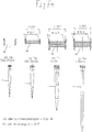
- Pipette syringe size (in microliters) Average diameter cone angle 1,000 - 10,000 14.3 mm 4.35 ° 100 - 5,000 12.4 mm 4.00 ° 500 - 2,500 9.3 mm 3.78 ° 50 - 1,000 7.1 mm 2.71 ° 50 - 1,250 7.1 mm 2.48 ° 20-30 or 2-20 4.4 mm 6.99 ° 0,5 - 20 3.3 mm 6.68 ° 0.1-20 or 0.1-10 2.95
- the pipette tip which is designed for a projection with one of the above combinations of medium diameter and cone angle, has a pipette tip size specified for this combination in the above table.
- a tolerance of +/- 7% applies to the diameter data in the above table.
- a tolerance of +/- 0.05 mm applies to the diameter data in the above table and / or a tolerance of +/- 0.3 ° for the angle data in the above table.
- a circumferential lower recess is provided on the inner circumference of the tubular body between the sealing projection and the brake region, and / or a circumferential upper recess is provided on the inner circumference of the tubular body between the sealing projection and the supporting projection.
- the wall thickness is reduced.
- the elastic deformability of the sealing bead is promoted with a relatively flat spring characteristic.
- the upper recess and / or the lower recess is not at the neck when the pipette tip is sealingly clamped on the approach.
- the upper recess is a specific embodiment of the above-mentioned upper portion of the seating area
- the lower recess is a specific embodiment of the above-mentioned lower portion of the seat portion.
- the relatively large wall thickness in the region of the support projection is advantageous for the rigidity of the support projection and the lateral support of the pipette tip.
- the pipette tip When manufacturing the pipette tip by injection molding, it is preferable to design and dimension the lower recess and / or the upper recess such that an allowable forced removal of the pipette tip from a core for molding the inner contour of the pipette tip is possible. Under this condition, a reduction of the material volume in the head area of the pipette tip of about 20% can be achieved.
- the lower recess and / or the upper recess in a longitudinal section through the body has a rounded contour.
- the rounded contour also favors the elastic deformability of the sealing projection. Further, it is advantageous for injection molding by fostering the stripping of pipette tips from needle cores to form the inner contour of the pipette tips.
- the contour of the lower recess smoothly passes in a longitudinal section through the body in the contour of the braking area and / or the sealing projection and / or goes over the contour of the upper Recess in a longitudinal section through the body smoothly into the contour of the sealing projection and / or the support projection over.
- the smooth transition from the upper recess to the support projection is also advantageous for the rigidity of the support projection.
- the sealing projection and / or the supporting projection in a longitudinal section through the body in each case the contour of a wave crest and / or has the lower recess and / or the upper recess in a longitudinal section through the body in each case the contour of a wave trough.
- the support projection is designed and dimensioned so that it just rests against the projection or is spaced by a gap from the approach, if the approach to the system at the brake area, if necessary, with a small deformation of the braking area in the pipette tip is used. This ensures that the support projection rests without bias on the approach.
- the support projection is designed and dimensioned so that it is plastically deformed when the approach is applied to the brake area. In this case, the plastic deformation of the support projection can compensate for a different depression of the approach in the pipette tip under different deformation of the braking area. Also in this embodiment, the support projection is due to the plastic deformation without bias on the approach.
- the sealing projection, braking region and supporting projection are formed such that the sealing projection can be clamped sealingly onto the projection with elastic deformation, wherein the braking region bears further down on the projection and the supporting projection by a circumferential gap with a gap width of not more than 0.2 mm , preferably a maximum of 0.15 mm, preferably a maximum of 0.1 mm, preferably a maximum of 0.08 mm is spaced from the approach.
- the pipette tip has an upwardly widening insertion region above the support projection.
- the insertion area facilitates the insertion of the approach into the pipette tip.
- the insertion region smoothly merges into the support projection. This promotes a stiff support projection, which supports the pipette tip laterally stable on the approach.
- the pipette tip has a larger outside diameter than below in a head section extending from the upper opening to the braking area.
- the head section serves to hold the pipette tip on a support. He also contributes to the stiffening of the seating area in the region of the support projection.
- the pipette tip at the bottom of the head region on the outside a paragraph for supporting on a support is provided.
- the pipette tip is made of a plastic. This is advantageous for the execution as a disposable part. According to one preferred embodiment, the pipette tip is made in one piece from a plastic.
- the pipette tip is made of a polyolefin, preferably polypropylene or polyethylene.
- the pipette tip is translucent, preferably transparent. Further preferably, the pipette tip is made by injection molding.
- the inner and / or outer diameter of the pipette tip increases from the lower opening to the upper opening.
- the pipette tip has a tubular body having a lower opening at the lower end for passage of liquid and an upper opening at the upper end, the body having a seating area adjacent to the upper opening for fitting to a conical one Approach of a pipetting device, which at the inner periphery of the tubular body at a distance from the upper opening a circumferential, inwardly projecting sealing projection, below the sealing protrusion a circumferential, stronger than the neck tapered braking area and above the sealing projection a circumferential, inwardly projecting Support projection, the pipetting device has at least one conical approach for attaching the pipette tip, which has a hole at the lower end of the neck with a displacement device for air in the Pipettiervorraum is connected, wherein the seating area is formed so that the sealing projection with elastic deformation sealingly clamped onto the approach, the brake area is applied further down the approach and the support projection rests without bias on the approach or spaced by a
- top and derived therefrom, such as “above” and “below”, refer to the orientation of a pipette tip during pipetting, in which the pipette tip is vertically aligned and the lower openings are at the bottom and the upper opening at the top ,
- a pipette tip 1 has an elongate, tubular body 2 which has a lower opening 4 at the lower end 3 and an upper opening 6 at the upper end 5.
- the lower opening 4 is smaller than the upper opening 6.
- the inner and / or outer diameter of the tubular body 2 increases from the lower opening 4 toward the upper opening 6.
- the tubular body 2 at the bottom has a conical starting portion 7, above a middle portion 8 with a smaller cone angle than the starting portion 7 and above a head portion 9 with larger outer dimensions than the central portion 8.
- At the bottom of the head portion 9 runs outwardly with respect to the central portion 8 outward paragraph 10 um.
- the paragraph 10 serves to support on the edge of a hole of a wearer.
- the head portion 9 has at the bottom a first frustoconical or cylindrical head portion 11 with the shoulder 10 at the bottom.
- the first frusto-conical head part can expand upwards or downwards.
- the first frusto-conical or cylindrical head part 11 is connected to an upwardly flared, second frusto-conical head part 12 of the head section 9.
- the second frusto-conical head part 12 has on the outside of the circumference a series of teardrop-shaped, outwardly projecting profiles 13.
- the middle section 8 Adjacent to the shoulder 10, the middle section 8 has a short transition area 14 with a larger cone angle on the outside than the arranged underneath main part of the central portion 8.
- the transition region 14 is connected by a radius to the main part of the central portion 8.
- a radially inwardly projecting sealing projection 16 in the form of a bead.
- a radially inwardly projecting sealing projection 16 in the form of a bead.
- an upwardly widening braking area 17 (brake ramp) to.
- the braking region 17 extends from a lower edge region of the head section 9 up to an upper edge region of the middle section 8.
- an inwardly projecting support projection 18 in the form of a bead passes.
- the lower recess 19 smoothly merges into the sealing projection 16 at the top and smoothly into the braking region 17 at the bottom.
- the upper recess 20 smoothly merges into the sealing projection 16 and smoothly into the support projection 19 at the top.
- an upwardly widening insertion region 21 connects.
- the insertion region 21 is conical at the top and goes smoothly down into the support projection 18.
- the sealing projection 16, brake area 17, support projection 18 and lower recess 19 and upper recess 20 comprising part of the pipette tip 1 is a seating area 22, which serves to releasably hold the pipette tip 1 at a neck of a pipette.
- a longitudinal section through the body 2 thus has the inner contour of the pipette tip 1 from the braking area 17 to the support projection 18 a wave-shaped course, braking area 17, sealing projection 16 and support projection 18 peaks and the lower recess 19 and the upper recess 20 wave troughs.
- the seating area 22 thus has its lowest wall thicknesses in the region of the wave troughs below and above the sealing projection 16. He has the greatest wall thicknesses on the sealing projection 16, support projection 18 and brake area 17.
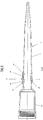
- a hand-held pipette 23 has a housing 24 in the form of a handle, which contains a displacement device 25 for displacing air and to which an actuating element 26 for actuating the displacement device 25 and an ejector 27 with an associated further actuating element 28 are arranged.
- a standardized conical projection 29 is arranged on the housing 24.
- a pipette tip 1 can be attached to the projection 29.
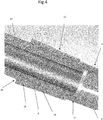
- Fig. 3 and 4 are on insertion of the pipette tip 1 with the seat portion 22 on the projection 29 of the sealing projection 16 elastically deformed. Due to the wave troughs 19, 20, the elasticity in the region of the sealing projection 16 is greater and the spring characteristic of the deformation of the sealing region is flatter than in conventional pipette tips. As a result, the Aufsteckkraft and ejection force is reduced.
- the lower end of the lug 29 abuts on the braking area 17, whereby a stop is effected.
- the Aufsteckamba can be braked by the braking area 17 by this is deformed.
- the braking area 17 is plastically deformed, so that the release force is not significantly increased by the braking area 17.
- the inclination of the braking area 17 reduces the frictional forces between the shoulder 29 and the braking area 17 anyway.
- the support projection 18 is matched to the projection 29, that it bears against the projection 29 without bias, or is spaced therefrom by a small gap. In the example, there is a circumferential gap 30 with a gap width of 0.08 mm.
- the support projection 18 prevents tilting of the pipette tip 1 on the projection 29, without increasing Aufsteckkraft and ejection force.
- the support projection 18 is relatively stiff due to its relatively large wall thickness, so that it does not yield when tilted the pipette tip 1.
- the invention includes possible embodiments in which the support projection 18 is plastically deformed by insertion of the lug 29. Due to the plastic deformation of the support projection 18 as it were without bias on the lug 29 so that it does not increase the release force. By the system of the support projection 18 on the lug 29 tilting is particularly effectively prevented.
- the elastic deformation of the sealing projection 16 by insertion of the projection 29 is in Fig. 5 illustrated.
- the additional registered inner contour within the Wall thickness of the head region 9 illustrates the elastic deformation of the sealing projection 16.
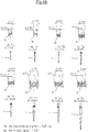
- Fig. 6a . b each show the mean diameter and the cone angle of a standardized conical projection 29 over an associated pipette tip 1 with a certain tip size.
- the mean diameter is given in millimeters and the cone angle in degrees.
- the mean diameter of the lug 29 refers to a diameter between the lower and the upper end of the lug 29. It need not necessarily be a diameter which is located exactly in the middle between the lower and the upper end of the lug. However, the average diameter may also fall exactly in the middle between the lower end and the upper end of the lug 29. According to one embodiment of the invention, it falls exactly in the middle between the lower end and the upper end of the projection 29th
- Fig. 6a . b the tolerances are given for the mean diameter (+/- 0.05 mm) and for the angle data (+/- 0.3 °).
- the lugs 29 are manufactured with appropriate tolerances.
Abstract
Pipettenspitze mit einem röhrchenförmigen Körper mit einer unteren Öffnung an dem unteren Ende für den Durchgang von Flüssigkeit und einer oberen Öffnung an dem oberen Ende, wobei der Körper neben der oberen Öffnung einen Sitzbereich zum Aufstecken auf einen konischen Ansatz einer Pipettiervorrichtung aufweist, der am inneren Umfang des röhrchenförmigen Körpers in einem Abstand von der oberen Öffnung einen umlaufenden, nach innen vorstehenden Dichtvorsprung, unterhalb des Dichtvorsprungs einen umlaufenden, sich nach unten stärker als der Ansatz verjüngenden Bremsbereich und oberhalb des Dichtvorsprunges einen umlaufenden, nach innen vorstehenden Stützvorsprung aufweist und so ausgebildet ist, dass der Dichtvorsprung unter elastischer Verformung abdichtend auf den Ansatz aufklemmbar ist, wobei der Bremsbereich weiter unten am Ansatz anliegt und der Stützvorsprung weiter oben ohne Vorspannung am Ansatz anliegt oder durch einen umlaufenden Spalt vom Ansatz beabstandet ist.A pipette tip comprising a tubular body having a lower opening at the lower end for passage of liquid and an upper opening at the upper end, the body having, adjacent to the upper opening, a seating area for attachment to a conical neck of a pipetting device at the inner periphery the tube-shaped body at a distance from the upper opening has a circumferential, inwardly projecting sealing projection, below the sealing projection a circumferential, downwardly stronger than the neck tapered braking region and above the sealing projection has a circumferential, inwardly projecting support projection and is formed so that the sealing projection is sealingly clamped on the approach under elastic deformation, wherein the brake region is applied further down the approach and the support projection rests further up without bias at the approach or is spaced by a circumferential gap from the approach ,
Description
Die Erfindung bezieht sich auf eine Pipettenspitze.The invention relates to a pipette tip.
Pipettenspitzen werden zusammen mit Pipetten und anderen Dosiervorrichtungen zum Dosieren von Flüssigkeiten verwendet. Nachfolgend werden Pipetten und andere Dosiervorrichtungen zusammenfassend als "Pipettiervorrichtungen" bezeichnet. Pipettenspitzen haben einen länglichen, rohrförmigen Körper, der an dem unteren Ende eine untere Öffnung für den Durchgang von Flüssigkeit und an dem oberen Ende eine obere Öffnung zum Aufklemmen auf den Ansatz einer Pipettiervorrichtung hat. Bekannt sind standardisierte konische bzw. kegelstumpfförmige Ansätze mit einer Standardgeometrie, die von vielen Herstellern einheitlich verwendet wird und die für jede Pipettenspitzengröße durch einen spezifischen mittleren Durchmesser und durch einen spezifischen Konuswinkel des konischen Ansatzes gekennzeichnet ist. Bekannt sind auch Ansätze, die zwei umlaufende Ringe oder Wulste haben, die starr oder als elastische Dichtringe ausgebildet sind. Diese Ansätze kommen insbesondere bei Dosierautomaten zum Einsatz. Sie sind vielfach so dimensioniert, dass Pipettenspitzen auf sie aufklemmbar sind, die für das Aufklemmen auf die standardisierten konischen Ansätze dimensioniert sind.Pipette tips are used with pipettes and other dosing devices to dose liquids. Hereinafter, pipettes and other metering devices are collectively referred to as "pipetting devices". Pipette tips have an elongate, tubular body having at the lower end a lower opening for the passage of liquid and at the upper end an upper opening for clamping onto the neck of a pipetting device. Known are standardized conical or frusto-conical approaches with a standard geometry, which is used by many manufacturers uniformly and which is characterized for each pipette tip size by a specific mean diameter and by a specific cone angle of the conical approach. Also known are approaches that have two circumferential rings or beads that are rigid or designed as elastic sealing rings. These approaches are used in dosing machines in particular. They are often dimensioned so that pipette tips can be clamped on them, which are dimensioned for clamping on the standardized conical approaches.
Pipettiervorrichtungen weisen eine Gasverdrängungseinrichtung auf, die meistens ein Zylinder mit einem darin axial verschiebbaren Kolben ist. Die Gasverdrängungseinrichtung ist mit einem Durchgangsloch des Ansatzes verbunden. Die Pipettenspitze wird durch Eindrücken des Ansatzes der Pipettiervorrichtung in die obere Öffnung der Pipettenspitze abdichtend auf den Ansatz aufgeklemmt.Pipetting devices have a gas displacement device, which is usually a cylinder with a piston axially displaceable therein. The gas displacement device is connected to a through hole of the neck. The pipette tip is clamped by pressing the approach of the pipetting device in the upper opening of the pipette tip sealingly on the approach.
Mittels der Gasverdrängungseinrichtung wird eine Luftsäule verschoben, um Flüssigkeit in die auf dem Ansatz sitzende Pipettenspitze einzusaugen oder aus dieser auszustoßen. Wird die Luftsäule nach oben verschoben, wird eine bestimmte Flüssigkeitsmenge durch die untere Öffnung in die Pipettenspitze eingesogen. Durch Verschieben der Luftsäule nach unten wird eine Flüssigkeitsmenge durch die untere Öffnung aus der Pipettenspitze abgegeben.By means of the gas displacement device, an air column is displaced to suck liquid in the seated on the approach pipette tip or from to launch this. If the air column is displaced upwards, a certain amount of liquid is sucked through the lower opening in the pipette tip. By moving the air column down a quantity of liquid is discharged through the lower opening from the pipette tip.
Pipettiervorrichtungen haben meist einen Abwerfer, der auf den oberen Rand der Pipettenspitze wirkt, um diese vom Ansatz abzudrücken. Hierdurch wird vermieden, dass der Anwender die kontaminierte Pipettenspitze anfassen muss, um sie vom Ansatz abzustreifen.Pipetting devices usually have an ejector, which acts on the upper edge of the pipette tip to squeeze them from the approach. This avoids the user having to touch the contaminated pipette tip to wipe it off the neck.
Die Pipettiervorrichtung kann eine Handpipette sein, die der Anwender mit nur einer Hand halten und betätigen kann. Sie kann auch eine Dosierstation sein oder in eine Arbeitsstation (work station) integriert sein. In sämtlichen Fällen kann die Gasverdrängungseinrichtung manuell oder motorangetrieben sein. Das Aufstecken und Abwerfen der Pipettenspitze kann ebenfalls manuell oder motorangetrieben geschehen.The pipetting device may be a handheld pipette that the user can hold and manipulate with one hand. It can also be a metering station or a work station (work station) to be integrated. In all cases, the gas displacement device may be manual or motor driven. The attachment and ejection of the pipette tip can also be done manually or motor driven.
Zur Vermeidung von Fehlpipettierungen muss die Pipettenspitze abdichtend auf dem Ansatz fixiert sein. Außerdem dürfen die Kräfte für das Aufstecken und das Abwerfen der Pipettenspitze von dem Ansatz nicht zu hoch sein. Bei herkömmlichen Pipettenspitzen ist der Kontaktbereich mit dem konischen Ansatz kegelstumpfförmig. Beim Aufstecken werden die Pipettenspitzen am Umfang durch den Ansatz elastisch aufgeweitet. Die Federkennlinie ist steil, sodass hohe Aufsteckkräfte aufzubringen sind. Nach dem Aufstecken wirkt eine entsprechend hohe Haftreibung zwischen dem Ansatz und der Pipettenspitze. Diese Haftreibung muss beim Abwerfen der Pipettenspitze überwunden werden. Der Anwender wird durch die hohen Kräfte für das Aufstecken und Abwerfen der Pipettenspitze belastet. Soweit das Aufstecken und Abwerfen mittels motorischer Antriebe erfolgt, müssen diese entsprechend leistungsfähig sein und haben einen hohen Stromverbrauch.To avoid incorrect pipetting, the pipette tip must be sealingly fixed on the shoulder. In addition, the forces for attaching and dropping the pipette tip from the neck should not be too high. In conventional pipette tips, the contact area with the conical shoulder is frusto-conical. When attaching the pipette tips are widened elastically on the circumference by the approach. The spring characteristic is steep, so high Aufsteckkräfte are applied. After fitting, a correspondingly high static friction acts between the attachment and the pipette tip. This static friction must be overcome when the pipette tip is dropped. The user is burdened by the high forces for attaching and dropping the pipette tip. As far as the plugging and dropping by means of motor drives, they must be correspondingly powerful and have a high power consumption.
Die
Die
Die
Davon ausgehend liegt der Erfindung die Aufgabe zugrunde, eine Pipettenspitze zu schaffen, die gut abdichtend und sicher auf den Ansatz einer Pipettiervoruchtung aufklemmbar, mit reduziertem Kraftaufwand vom Ansatz abwerfbar ist und sich auch gut für kleinere Pipettenspitzengrößen eignet.Based on this, the present invention seeks to provide a pipette tip, the well-sealing and safe to the approach of Pipettieruchtuchtung clamped, can be thrown off the approach with reduced effort and is also well suited for smaller pipette tip sizes.
Die Aufgabe wird durch eine Pipettenspitze mit den Merkmalen von Anspruch 1 gelöst. Vorteilhafte Ausgestaltungen der Pipettenspitze sind in Unteransprüchen angegeben.The object is achieved by a pipette tip having the features of
Die erfindungsgemäße Pipettenspitze hat einen röhrchenförmigen Körper mit einer unteren Öffnung an dem unteren Ende für den Durchgang von Flüssigkeit und einer oberen Öffnung an dem oberen Ende, wobei der Körper neben der oberen Öffnung einen Sitzbereich zum Aufstecken auf einen konischen Ansatz einer Pipettiervorrichtung aufweist, der am Innenumfang des röhrchenförmigen Körpers in einem Abstand von der oberen Öffnung einen umlaufenden, nach innen vorstehenden Dichtvorsprung, unterhalb des Dichtvorsprungs einen umlaufenden, sich nach unten stärker als der Ansatz verjüngenden Bremsbereich und oberhalb des Dichtvorsprungs einen umlaufenden, nach innen vorstehenden Stützvorsprung aufweist und so ausgebildet ist, dass der Dichtvorsprung unter elastischer Verformung abdichtend auf den Ansatz aufklemmbar ist, wobei der Bremsbereich weiter unten am Ansatz anliegt und der Stützvorsprung weiter oben ohne Vorspannung am Ansatz anliegt oder durch einen umlaufenden Spalt vom Ansatz beabstandet ist.The pipette tip of the present invention has a tubular body having a lower opening at the lower end for passage of liquid and an upper opening at the upper end, the body having, adjacent to the upper opening, a seating area for attachment to a conical neck of a pipetting device located at Inner circumference of the tubular body at a distance from the upper opening a circumferential, inwardly projecting sealing projection, below the sealing projection has a circumferential, downwardly stronger than the neck tapered braking area and above the sealing projection has a circumferential, inwardly projecting support projection and is formed in that the sealing projection can be clamped sealingly onto the projection with elastic deformation, wherein the braking region bears further down on the projection and the supporting projection rests further up against the projection without pretension or by a circumferential gap from the Ans Atz is spaced.
Beim Aufstecken der erfindungsgemäßen Pipettenspitze auf einen konischen Ansatz einer Pipettiervorrichtung bewirkt die Flächenpressung im Bereich des Dichtvorsprungs eine elastische Verformung des Dichtvorsprungs. Durch eine geeignete Geometrie des Dichtvorsprungs, eine geringe Wandstärke der Pipettenspitze neben dem Bereich des Dichtvorsprungs und das Material der Pipettenspitze kann eine relativ flache Federkennlinie für die elastische Verformung des Dichtvorsprungs erreicht werden. Infolgedessen steigt die Aufsteckkraft mit dem Aufsteckweg verhältnismäßig sanft an. Hierfür hat gemäß einer bevorzugten Ausgestaltung der Pipettenspitze der Sitzbereich einen oberen Bereich, der zwischen Dichtvorsprung und Stützvorsprung am Innenumfang des röhrchenförmigen Körpers umläuft, und/oder einen unteren Bereich, der zwischen Dichtvorsprung und Bremsbereich am Innenumfang des röhrchenförmigen Körpers umläuft, und ist der Sitzbereich so ausgebildet, dass der obere Bereich und/oder der untere Bereich, mit geringerer elastischer Verformung als der Dichtvorsprung oder gar nicht am Ansatz anliegt, wenn die Pipettenspitze abdichtend auf den Ansatz aufgeklemmt ist.When attaching the pipette tip according to the invention to a conical projection of a pipetting device, the surface pressure in the region of the sealing projection causes an elastic deformation of the sealing projection. By a suitable geometry of the sealing projection, a small wall thickness of the pipette tip next to the region of the sealing projection and the material of the pipette tip can have a relatively flat spring characteristic for the elastic deformation the sealing projection can be achieved. As a result, the Aufsteckkraft increases relatively gently with the Aufsteckweg. For this purpose, according to a preferred embodiment of the pipette tip, the seating area has an upper area which circulates between the sealing projection and the supporting projection on the inner circumference of the tubular body, and / or a lower area which circulates between the sealing projection and the braking area on the inner circumference of the tubular body, and the seating area is such designed such that the upper portion and / or the lower portion, with less elastic deformation than the sealing projection or not at the neck rests when the pipette tip is sealingly clamped on the approach.
Das Aufstecken der Pipettenspitze auf den Ansatz wird durch den sich allmählich nach unten verjüngenden Bremsbereich (Bremsrampe) unterhalb des Dichtvorsprungs begrenzt. Hierfür verjüngt sich der Bremsbereich stärker als der Ansatz, sodass dieser beim Eindungen in den Sitzbereich auf den Bremsbereich trifft. Beispielsweise ist der Bremsbereich konisch, wobei sein Konuswinkel größer als der Konuswinkel des Ansatzes ist. Hierdurch wird der Aufsteckweg begrenzt. Die zwischen Pipettenspitze und Ansatz wirksame und beim Abwerfen zu überwindende Reibkraft zwischen Pipettenspitze und Ansatz wird hierdurch begrenzt. Die Geometrie des Bremsbereiches, die Wandstärke der Pipettenspitze in seinem Bereich und das Material der Pipettenspitze können so gewählt werden, dass der Bremsbereich beim Auftreffen des Ansatzes verformt wird, sodass die Aufsteckbewegung allmählich und nicht unvermittelt gestoppt wird. Das sanfte Stoppen der Aufsteckbewegung wirkt sich für den Anwender gelenkschonend aus. Zudem hat der Anwender die Möglichkeit, durch Nachdrücken der Pipettiervorrichtung mit dem Ansatz in die Pipettenspitze den festen Sitz der Pipettenspitze auf dem Ansatz zu verbessern. Ein starrer Anschlag bietet diese Möglichkeit nicht. Vorzugsweise wird hierbei der Bremsbereich plastisch verformt, sodass durch seine Verformung die Abwurfkraft nur geringfügig erhöht wird. Die Erfindung bezieht mögliche Ausgestaltungen mit elastisch oder elastisch und plastisch verformbarem Bremsbereich ein. Die zwischen Pipettenspitze und Ansatz wirkende und beim Abwerfen zu überwindende Reibkraft steigt bei elastischer Verformung des Bremsbereichs nur geringfügig an.The attachment of the pipette tip on the approach is limited by the gradually downwardly tapered braking area (braking ramp) below the sealing projection. For this purpose, the brake area tapers more than the approach, so that it meets the brake area when indenting in the seating area. For example, the braking area is conical, with its cone angle is greater than the cone angle of the approach. As a result, the Aufsteckweg is limited. The effective between the pipette tip and approach and to be overcome during ejection frictional force between the pipette tip and approach is limited thereby. The geometry of the brake area, the wall thickness of the pipette tip in its area and the material of the pipette tip can be selected so that the brake area is deformed when the approach of the approach, so that the Aufsteckbewegung is stopped gradually and not abruptly. The gentle stopping of the attachment movement has a gentle effect on the joints. In addition, the user has the opportunity to improve the tight fit of the pipette tip on the approach by pressing the pipette with the approach in the pipette tip. A rigid stop does not offer this possibility. Preferably, in this case, the braking area is plastically deformed, so that the ejection force is only slightly increased by its deformation. The The invention relates to possible embodiments with an elastically or elastically and plastically deformable braking region. The frictional force acting between the pipette tip and the projection and to be overcome during ejection increases only slightly when the braking region is elastically deformed.
Die mit verhältnismäßig geringer Reibkraft am Ansatz gehaltene Pipettenspitze darf beim Pipettieren nicht auf dem Ansatz kippen oder sich von diesem lösen, insbesondere wenn bei Abgabe der Probe an einer Wand eine seitliche Kraft auf die Pipettenspitze ausgeübt wird. Zum Abfangen von seitlichen Kräften weist die Pipettenspitze oben einen umlaufenden Stützvorsprung auf. Der Stützvorsprung liegt ohne Vorspannung am Ansatz an oder ist durch einen umlaufenden Spalt vom Ansatz beabstandet, sodass sie die Reibkräfte zwischen Pipettenspitze und Ansatz und damit die aufzubringenden Abwerfkräfte nicht erhöht. Dadurch, dass der Stützvorsprung vorspannungsfrei am Ansatz anliegt oder durch einen Spalt vom Ansatz beabstandet ist, werden Reibkräfte zwischen Stützvorsprung und Ansatz vermieden. Ein Kippen der Pipettenspitze auf dem Ansatz wird jedoch durch den Stützvorsprung unterbunden. Sofern der Stützvorsprung durch einen Spalt vom Ansatz beabstandet ist, ist der Spalt so gering bemessen, dass die Pipettenspitze durch elastische Verformung den Spalt überbrückt und an dem Stützvorsprung anliegt, ohne dass sich ihre Fixierung am Dichtvorsprung und am Bremsbereich löst. Aufgrund der Geometrie des Dichtvorsprunges, des Bremsbereiches und des Stützvorsprungs sind erfindungsgemäße Pipettenspitzen auch mit verhältnismäßig kleinen Pipettenspitzengrößen insbesondere unter 2,5 ml gut herstellbar. Die Erfindung eignet sich aber auch für die Herstellung verhältnismäßig großer Pipettenspitzen.The pipette tip held with relatively low frictional force at the neck must not tilt or become detached from the attachment during pipetting, especially if lateral force is exerted on the pipette tip when the sample is delivered to a wall. For trapping lateral forces, the pipette tip has a circumferential support projection on top. The support projection is without bias on the approach or is spaced by a circumferential gap from the approach, so they do not increase the frictional forces between the pipette tip and approach and thus the Abwerfkräfte applied. Due to the fact that the supporting projection bears on the projection without bias or is separated by a gap from the projection, frictional forces between the supporting projection and the projection are avoided. However, a tilting of the pipette tip on the approach is prevented by the support projection. If the support projection is spaced by a gap from the approach, the gap is dimensioned so small that the pipette tip bridges the gap by elastic deformation and rests against the support projection, without their fixation on the sealing projection and the brake area dissolves. Owing to the geometry of the sealing projection, the braking region and the supporting projection, pipette tips according to the invention can be produced well even with relatively small pipette tip sizes, in particular less than 2.5 ml. However, the invention is also suitable for the production of relatively large pipette tips.
Somit wird erfindungsgemäß eine sowohl für große als auch für kleine Pipettenspitzengrößen geeignete Pipettenspitze erreicht, die sicher abdichtend und geschützt vor Kippen durch seitlich angreifende Kräften auf einem Ansatz fixierbar und mit verhältnismäßig geringem Kraftaufwand vom Ansatz lösbar ist. Die erforderliche Aufsteckkraft kann der Anwender mittels Unterarm und Hand leicht aufbringen. Die geringe Abwurfkraft entlastet den Anwender einer Handpipette mit einem Abwerfer, der mittels des Daumens zu betätigen ist. Ebenso werden motorisch verlagerte Pipettiervorrichtungen und motorisch angetriebene Abwerfer durch die erfindungsgemäße Pipettenspitze entlastet.Thus, according to the invention, a pipette tip suitable for both large and small pipette tip sizes is achieved, which securely seals and protected against tilting by laterally acting forces on a neck fixable and with relatively little effort from the approach is solvable. The user can easily apply the required attachment force by means of his forearm and hand. The low release force relieves the user of a hand-held pipette with an ejector that can be operated by means of the thumb. Likewise, motor-displaced pipetting devices and motor-driven ejectors are relieved by the pipette tip according to the invention.
Ferner wird die Aufgabe durch eine Pipettenspitze mit den nachfolgenden Merkmalen gelöst:
- Die erfindungsgemäße Pipettenspitze hat einen röhrchenförmigen Körper mit einer unteren Öffnung an dem unteren Ende für den Durchgang von Flüssigkeit und einer oberen Öffnung an dem oberen Ende, wobei der Körper neben der oberen Öffnung einen Sitzbereich zum Aufstecken auf einen konischen Ansatz einer Pipettiervorrichtung aufweist, der am inneren Umfang des röhrchenförmigen Körpers in einem Abstand von der oberen Öffnung einen umlaufenden, nach innen vorstehenden Dichtvorsprung, unterhalb des Dichtvorsprungs einen umlaufenden, sich nach unten stärker als der Ansatz verjüngenden Bremsbereich und oberhalb des Dichtvorsprungs einen umlaufenden, nach innen vorstehenden Stützvorsprung aufweist und so ausgebildet ist, dass der Dichtvorsprung und der Bremsbereich von der Mantelfläche eines gedachten Konus, dessen Achse mit der Mittelachse des röhrchenförmigen Körpers zusammenfällt, geschnitten werden, und der Stützvorsprung an der Außenseite der Mantelfläche des gedachten Konus anliegt oder außerhalb der Außenseite der Mantelfläche des gedachten Konus angeordnet ist. Hierbei entspricht der gedachte Konus, auf den sich die Gestaltung des Sitzbereiches bezieht, dem konischen Ansatz, auf den die Pipettenspitze abdichtend aufklemmbar ist. Gemäß einer bevorzugten Ausgestaltung hat der Sitzbereich einen oberen Bereich, der zwischen dem Dichtvorsprung und dem Stützvorsprung am inneren Umfang des röhrchenförmigen Körpers umläuft und der an der Außenseite der Mantelfläche des gedachten Konus anliegt oder außerhalb der Außenseite der Mantelfläche des gedachten Konus angeordnet ist. Gemäß einer weiteren Ausgestaltung hat der Sitzbereich einen unteren Bereich, der zwischen Stützvorsprung und Bremsbereich am inneren Umfang des röhrchenförmigen Körpers umläuft und an der Außenseite der Mantelfläche des gedachten Konus anliegt oder außerhalb der Außenseite der Mantelfläche des gedachten Konus angeordnet ist. Der obere Bereich und der untere Bereich bewirken eine relativ flache Federkennlinie für die elastische Verformung des Dichtvorsprungs. Vorzugsweise handelt es sich hierbei um eine obere Vertiefung und/oder eine untere Vertiefung am Innenumfang des röhrchenförmigen Körpers.
- The pipette tip of the present invention has a tubular body having a lower opening at the lower end for passage of liquid and an upper opening at the upper end, the body having, adjacent to the upper opening, a seating area for attachment to a conical neck of a pipetting device located at inner circumference of the tubular body at a distance from the upper opening a circumferential, inwardly projecting sealing projection, below the sealing projection has a circumferential, downwardly stronger than the neck tapered braking region and above the sealing projection has a circumferential, inwardly projecting support projection and so formed in that the sealing projection and the braking portion are cut by the lateral surface of an imaginary cone whose axis coincides with the central axis of the tubular body, and the supporting projection on the outside of the lateral surface of the geda cust cone is located or outside the outside of the lateral surface of the imaginary cone is arranged. Here, the imaginary cone to which the design of the seating area refers to the conical approach to which the pipette tip is sealingly clamped. According to a preferred embodiment, the seating area has a upper portion which circulates between the sealing projection and the support projection on the inner circumference of the tubular body and which abuts on the outer side of the lateral surface of the imaginary cone or outside the outside of the lateral surface of the imaginary cone is arranged. According to a further embodiment, the seating area has a lower area which circulates between the supporting projection and the braking area on the inner circumference of the tubular body and rests on the outer side of the lateral surface of the imaginary cone or outside the outer surface of the lateral surface of the imaginary cone. The upper portion and the lower portion cause a relatively flat spring characteristic for the elastic deformation of the sealing projection. Preferably, this is an upper recess and / or a lower recess on the inner circumference of the tubular body.
Die vorstehende Pipettenspitze weist gemäß einer vorteilhaften Ausgestaltung die Merkmale der Pipettenspitze gemäß mindestens einem der Ansprüche 1 bis 14 auf.The above pipette tip has according to an advantageous embodiment, the features of the pipette tip according to at least one of
Die erfindungsgemäße Pipettenspitze ist für konische Ansätze mit beliebigen Abmessungen geeignet. Vorzugsweise ist die erfindungsgemäße Pipettenspitze für das Verbinden mit einem standardisierten konischen Ansatz ausgebildet. Hierbei ist die Pipettenspitze so ausgebildet, dass der Dichtvorsprung unter elastischer Vorspannung abdichtend auf den Ansatz aufklemmbar ist, wobei der Bremsbereich am Ansatz anliegt und der Stützvorsprung ohne Vorspannung am Ansatz anliegt oder durch einen umlaufenden Spalt vom Ansatz beabstandet ist, wenn der konische Ansatz einen mittleren Durchmesser und einen Konuswinkel gemäß einer der nachfolgenden Kombinationen hat:
Hierbei sind der mittlere Durchmesser und der Konuswinkel Maße einer konischen Sitzfläche des Ansatzes zum Aufstecken einer Pipettenspitze.Here, the average diameter and the cone angle dimensions of a conical seat surface of the approach for attaching a pipette tip.
Gemäß einer weiteren Ausgestaltung der Erfindung weist die Pipettenspitze, die für einen Ansatz mit einer der obigen Kombinationen von mittlerem Durchmesser und Konuswinkel ausgebildet ist, eine für diese Kombination in der obigen Tabelle angegebene Pipettenspitzengröße auf.According to a further embodiment of the invention, the pipette tip, which is designed for a projection with one of the above combinations of medium diameter and cone angle, has a pipette tip size specified for this combination in the above table.
Gemäß einer weiteren Ausgestaltung gilt für die Durchmesserangaben in der obigen Tabelle eine Toleranz von +/- 7 %.According to a further embodiment, a tolerance of +/- 7% applies to the diameter data in the above table.
Gemäß einer alternativen Ausgestaltung zu der vorstehenden Ausgestaltung gilt für die Durchmesserangaben in der obigen Tabelle eine Toleranz von +/- 0,14 mm und/oder für die Winkelangaben eine Toleranz von +/- 0,6°.According to an alternative embodiment to the above embodiment applies to the diameter data in the above table, a tolerance of +/- 0.14 mm and / or for the angle specifications, a tolerance of +/- 0.6 °.
Gemäß einer weiteren Ausgestaltung gilt für die Durchmesserangaben in der obigen Tabelle eine Toleranz von +/- 0,05 mm und/oder für die Winkelangaben in der obigen Tabelle eine Toleranz von +/- 0,3°.According to a further embodiment, a tolerance of +/- 0.05 mm applies to the diameter data in the above table and / or a tolerance of +/- 0.3 ° for the angle data in the above table.
Gemäß einer Ausgestaltung ist am inneren Umfang des röhrchenförmigen Körpers zwischen Dichtvorsprung und Bremsbereich eine umlaufende untere Vertiefung vorhanden und/oder ist am inneren Umfang des röhrchenförmigen Körpers zwischen Dichtvorsprung und Stützvorsprung eine umlaufende obere Vertiefung vorhanden. Durch die untere Vertiefung und/oder die obere Vertiefung wird die Wandstärke reduziert. Hierdurch wird die elastische Verformbarkeit des Dichtwulstes mit einer relativ flachen Federkennlinie gefördert. Die obere Vertiefung und/oder die untere Vertiefung liegt nicht am Ansatz an, wenn die Pipettenspitze abdichtend auf den Ansatz aufgeklemmt ist. Die obere Vertiefung ist eine spezielle Ausführung des oben erwähnten oberen Bereichs des Sitzbereiches und die untere Vertiefung ist eine spezielle Ausführung des oben erwähnten unteren Bereichs des Sitzbereichs.According to one embodiment, a circumferential lower recess is provided on the inner circumference of the tubular body between the sealing projection and the brake region, and / or a circumferential upper recess is provided on the inner circumference of the tubular body between the sealing projection and the supporting projection. Through the lower recess and / or the upper recess, the wall thickness is reduced. As a result, the elastic deformability of the sealing bead is promoted with a relatively flat spring characteristic. The upper recess and / or the lower recess is not at the neck when the pipette tip is sealingly clamped on the approach. The upper recess is a specific embodiment of the above-mentioned upper portion of the seating area, and the lower recess is a specific embodiment of the above-mentioned lower portion of the seat portion.
Die relativ große Wandstärke im Bereich des Stützvorsprungs ist von Vorteil für die Steifigkeit des Stützvorsprungs und das seitliche Abstützen der Pipettenspitze.The relatively large wall thickness in the region of the support projection is advantageous for the rigidity of the support projection and the lateral support of the pipette tip.
Bei Herstellung der Pipettenspitze durch Spritzgießen ist vorzugsweise die untere Vertiefung und/oder die obere Vertiefung so zu gestalten und bemessen, dass eine zulässige Zwangsentformung der Pipettenspitze von einem Kern zum Formen der Innenkontur der Pipettenspitze möglich ist. Unter dieser Voraussetzung kann eine Reduzierung des Materialvolumens im Kopfbereich der Pipettenspitze von ca. 20 % erreicht werden.When manufacturing the pipette tip by injection molding, it is preferable to design and dimension the lower recess and / or the upper recess such that an allowable forced removal of the pipette tip from a core for molding the inner contour of the pipette tip is possible. Under this condition, a reduction of the material volume in the head area of the pipette tip of about 20% can be achieved.
Gemäß einer weiteren Ausgestaltung weist die untere Vertiefung und/oder die obere Vertiefung in einem Längsschnitt durch den Körper eine gerundete Kontur auf. Die gerundete Kontur begünstigt ebenfalls die elastische Verformbarkeit des Dichtvorsprungs. Ferner ist sie vorteilhaft für die Herstellung durch Spritzgießen, indem sie das Abstreifen der Pipettenspitzen von nadelförmigen Kernen zum Formen der Innenkontur der Pipettenspitzen begünstigt.According to a further embodiment, the lower recess and / or the upper recess in a longitudinal section through the body has a rounded contour. The rounded contour also favors the elastic deformability of the sealing projection. Further, it is advantageous for injection molding by fostering the stripping of pipette tips from needle cores to form the inner contour of the pipette tips.
Zur Verbesserung der elastischen Verformbarkeit des Dichtvorsprungs und der Herstellung der Pipettenspitzen durch Spritzgießen geht gemäß einer weiteren Ausgestaltung die Kontur der unteren Vertiefung in einem Längsschnitt durch den Körper glatt in die Kontur des Bremsbereiches und/oder des Dichtvorsprungs über und/oder geht die Kontur der oberen Vertiefung in einem Längsschnitt durch den Körper glatt in die Kontur des Dichtvorsprungs und/oder des Stützvorsprungs über. Der glatte Übergang von der oberen Vertiefung zum Stützvorsprung ist zudem von Vorteil für die Steifigkeit des Stützvorsprungs.To improve the elastic deformability of the sealing projection and the production of the pipette tips by injection molding, the contour of the lower recess smoothly passes in a longitudinal section through the body in the contour of the braking area and / or the sealing projection and / or goes over the contour of the upper Recess in a longitudinal section through the body smoothly into the contour of the sealing projection and / or the support projection over. The smooth transition from the upper recess to the support projection is also advantageous for the rigidity of the support projection.
Gemäß einer weiteren Ausgestaltung weist der Dichtvorsprung und/oder der Stützvorsprung in einem Längsschnitt durch den Körper jeweils die Kontur eines Wellenberges auf und/oder weist die untere Vertiefung und/oder die obere Vertiefung in einem Längsschnitt durch den Körper jeweils die Kontur eines Wellentales auf.According to a further embodiment, the sealing projection and / or the supporting projection in a longitudinal section through the body in each case the contour of a wave crest and / or has the lower recess and / or the upper recess in a longitudinal section through the body in each case the contour of a wave trough.
Gemäß einer bevorzugten Variante der Erfindung ist der Stützvorsprung so gestaltet und bemessen, dass er gerade an dem Ansatz anliegt oder durch einen Spalt von dem Ansatz beabstandet ist, wenn der Ansatz bis zur Anlage am Bremsbereich ggf. unter einer geringen Verformung des Bremsbereichs in die Pipettenspitze eingesetzt ist. Hierdurch ist gewährleistet, dass der Stützvorsprung ohne Vorspannung am Ansatz anliegt. Gemäß einer alternativen Variante der Erfindung ist der Stützvorsprung so gestaltet und bemessen, dass er plastisch verformt wird, wenn der Ansatz am Bremsbereich anliegt. Hierbei kann die plastische Verformung des Stützvorsprunges ein unterschiedlich tiefes Einpressen des Ansatzes in die Pipettenspitze unter unterschiedlicher Verformung des Bremsbereiches kompensieren. Auch bei dieser Ausgestaltung liegt der Stützvorsprung aufgrund der plastischen Verformung ohne Vorspannung am Ansatz an.According to a preferred variant of the invention, the support projection is designed and dimensioned so that it just rests against the projection or is spaced by a gap from the approach, if the approach to the system at the brake area, if necessary, with a small deformation of the braking area in the pipette tip is used. This ensures that the support projection rests without bias on the approach. According to an alternative variant of the invention, the support projection is designed and dimensioned so that it is plastically deformed when the approach is applied to the brake area. In this case, the plastic deformation of the support projection can compensate for a different depression of the approach in the pipette tip under different deformation of the braking area. Also in this embodiment, the support projection is due to the plastic deformation without bias on the approach.
Gemäß einer weiteren Ausgestaltung sind Dichtvorsprung, Bremsbereich und Stützvorsprung so ausgebildet, dass der Dichtvorsprung unter elastischer Verformung abdichtend auf den Ansatz aufklemmbar ist, wobei der Bremsbereich weiter unten am Ansatz anliegt und der Stützvorsprung durch einen umlaufenden Spalt mit einer Spaltweite von maximal 0,2 mm, vorzugsweise maximal 0,15 mm, vorzugsweise maximal 0,1 mm, vorzugsweise maximal 0,08 mm vom Ansatz beabstandet ist.According to a further embodiment, the sealing projection, braking region and supporting projection are formed such that the sealing projection can be clamped sealingly onto the projection with elastic deformation, wherein the braking region bears further down on the projection and the supporting projection by a circumferential gap with a gap width of not more than 0.2 mm , preferably a maximum of 0.15 mm, preferably a maximum of 0.1 mm, preferably a maximum of 0.08 mm is spaced from the approach.
Gemäß einer weiteren Ausgestaltung weist die Pipettenspitze oberhalb des Stützvorsprungs einen sich nach oben erweiternden Einführbereich auf. Der Einführbereich erleichtert das Einführen des Ansatzes in die Pipettenspitze.According to a further embodiment, the pipette tip has an upwardly widening insertion region above the support projection. The insertion area facilitates the insertion of the approach into the pipette tip.
Gemäß einer weiteren Ausgestaltung geht der Einführbereich glatt in den Stützvorsprung über. Dies begünstigt einen steifen Stützvorsprung, welcher die Pipettenspitze seitlich stabil auf dem Ansatz abstützt.According to a further embodiment, the insertion region smoothly merges into the support projection. This promotes a stiff support projection, which supports the pipette tip laterally stable on the approach.
Gemäß einer weiteren Ausgestaltung weist die Pipettenspitze in einem von der oberen Öffnung bis zum Bremsbereich erstreckten Kopfabschnitt außen einen größeren Durchmesser als darunter auf. Der Kopfabschnitt dient zum Halten der Pipettenspitze auf einem Träger. Ferner trägt er zur Versteifung des Sitzbereichs im Bereich des Stützvorsprungs bei.According to a further embodiment, the pipette tip has a larger outside diameter than below in a head section extending from the upper opening to the braking area. The head section serves to hold the pipette tip on a support. He also contributes to the stiffening of the seating area in the region of the support projection.
Gemäß einer weiteren Ausgestaltung weist die Pipettenspitze am unteren Rand des Kopfbereiches außen einen Absatz zum Abstützen auf einem Träger auf.According to a further embodiment, the pipette tip at the bottom of the head region on the outside a paragraph for supporting on a support.
Gemäß einer weiteren Ausgestaltung ist die Pipettenspitze aus einem Kunststoff hergestellt. Dies ist vorteilhaft für die Ausführung als Einmalteil. Gemäß einer bevorzugten Ausgestaltung ist die Pipettenspitze einteilig aus einem Kunststoff hergestellt.According to a further embodiment, the pipette tip is made of a plastic. This is advantageous for the execution as a disposable part. According to one preferred embodiment, the pipette tip is made in one piece from a plastic.
Gemäß einer weiteren Ausgestaltung ist die Pipettenspitze aus einem Polyolefin hergestellt, vorzugsweise aus Polypropylen oder aus Polyethylen.According to another embodiment, the pipette tip is made of a polyolefin, preferably polypropylene or polyethylene.
Gemäß einer weiteren Ausgestaltung ist die Pipettenspitze lichtdurchlässig, vorzugsweise durchsichtig. Weiterhin vorzugsweise ist die Pipettenspitze durch Spritzgießen hergestellt.According to a further embodiment, the pipette tip is translucent, preferably transparent. Further preferably, the pipette tip is made by injection molding.
Vorzugsweise nimmt der innere und/oder äußere Durchmesser der Pipettenspitze von der unteren Öffnung zur oberen Öffnung zu.Preferably, the inner and / or outer diameter of the pipette tip increases from the lower opening to the upper opening.
Ferner wird die Aufgabe durch ein System mit den Merkmalen von Anspruch 15 gelöst.Furthermore, the object is achieved by a system having the features of claim 15.
Bei dem erfindungsgemäßen System aus Pipettenspitze und Pipettiervorrichtung hat die Pipettenspitze einen röhrchenförmigen Körper mit einer unteren Öffnung an dem unteren Ende für den Durchgang von Flüssigkeit und einer oberen Öffnung an dem oberen Ende, wobei der Körper neben der oberen Öffnung einen Sitzbereich zum Aufstecken auf einen konischen Ansatz einer Pipettiervorrichtung aufweist, der am inneren Umfang des röhrchenförmigen Körpers in einem Abstand von der oberen Öffnung einen umlaufenden, nach innen vorstehenden Dichtvorsprung, unterhalb des Dichtvorsprungs einen umlaufenden, sich stärker als der Ansatz verjüngenden Bremsbereich und oberhalb des Dichtvorsprungs einen umlaufenden, nach innen vorstehenden Stützvorsprung aufweist, die Pipettiervorrichtung mindestens einen konischen Ansatz zum Aufstecken der Pipettenspitze aufweist, der über ein Loch am unteren Ende des Ansatzes mit einer Verdrängungseinrichtung für Luft in der Pipettiervorrichtung verbunden ist, wobei der Sitzbereich so ausgebildet ist, dass der Dichtvorsprung unter elastischer Verformung abdichtend auf den Ansatz aufklemmbar ist, wobei der Bremsbereich weiter unten am Ansatz anliegt und der Stützvorsprung weiter oben ohne Vorspannung am Ansatz anliegt oder durch einen umlaufenden Spalt vom Ansatz beabstandet ist.In the pipette tip and pipetting device system of the present invention, the pipette tip has a tubular body having a lower opening at the lower end for passage of liquid and an upper opening at the upper end, the body having a seating area adjacent to the upper opening for fitting to a conical one Approach of a pipetting device, which at the inner periphery of the tubular body at a distance from the upper opening a circumferential, inwardly projecting sealing projection, below the sealing protrusion a circumferential, stronger than the neck tapered braking area and above the sealing projection a circumferential, inwardly projecting Support projection, the pipetting device has at least one conical approach for attaching the pipette tip, which has a hole at the lower end of the neck with a displacement device for air in the Pipettiervorrichtung is connected, wherein the seating area is formed so that the sealing projection with elastic deformation sealingly clamped onto the approach, the brake area is applied further down the approach and the support projection rests without bias on the approach or spaced by a circumferential gap from the approach is.
Vorteilhafte Ausgestaltungen des erfindungsgemäßen Systems weisen eine Pipettenspitze gemäß mindestens einer der oben beschriebenen Ausgestaltungen auf.Advantageous embodiments of the system according to the invention have a pipette tip according to at least one of the embodiments described above.
Nachfolgend wird die Erfindung anhand der anliegenden Zeichnungen eines Ausführungsbeispiels näher erläutert. In den Zeichnungen zeigen:
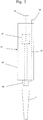
- Fig. 1a-e
- eine Pipettenspitze in Seitenansicht (
Fig. 1a ), in einem Längsschnitt (Fig. 1b ), in vergrößerter Unteransicht (Fig. 1c ), in vergrößerter Draufsicht (Fig. 1d ) und in einem vergrößerten Längsschnitt durch den Sitzbereich (Fig. 1e ); - Fig. 2
- eine Pipette mit Ansatz beim Aufstecken der Pipettenspitze von
Fig. 1 in einer grobschematischen Seitenansicht; - Fig. 3
- die Pipettenspitze von
Fig. 1 aufgeklemmt auf den Ansatz der Pipette in einem vergrößerten Längsschnitt; - Fig. 4
- der Sitzbereich der Pipettenspitze aufgeklemmt auf den Ansatz in einem vergrößerten Längsschnitt;
- Fig. 5
- der Sitzbereich in unverformtem Zustand und mit verformtem Dichtvorsprung in einem Längsschnitt;
- Fig. 6a+b
- mittlerer Durchmesser und Konuswinkel standardisierter konischer Ansätze zum Aufstecken von Pipettenspitzen verschiedener Größen in einer Übersicht.
- Fig. 1a-e
- a pipette tip in side view (
Fig. 1a ), in a longitudinal section (Fig. 1b ), in an enlarged bottom view (Fig. 1c ), in enlarged plan view (Fig. 1d ) and in an enlarged longitudinal section through the seating area (Fig. 1e ); - Fig. 2
- a pipette with approach when attaching the pipette tip of
Fig. 1 in a rough schematic side view; - Fig. 3
- the pipette tip of
Fig. 1 clamped on the approach of the pipette in an enlarged longitudinal section; - Fig. 4
- the seating area of the pipette tip clamped on the approach in an enlarged longitudinal section;
- Fig. 5
- the seating area in undeformed state and with deformed sealing projection in a longitudinal section;
- Fig. 6a + b
- average diameter and cone angle of standardized conical approaches for attaching pipette tips of various sizes in an overview.
In der vorliegenden Anmeldung beziehen sich die Angaben "oben" sowie davon abgeleitete Angaben wie "oberhalb" und "unterhalb" auf die Ausrichtung einer Pipettenspitze beim Pipettieren, bei der die Pipettenspitze vertikal ausgerichtet ist und sich die untere Öffnungen unten und die obere Öffnung oben befindet.In the present application, the terms "top" and derived therefrom, such as "above" and "below", refer to the orientation of a pipette tip during pipetting, in which the pipette tip is vertically aligned and the lower openings are at the bottom and the upper opening at the top ,
Gemäß
Generell nimmt der innere und/oder äußere Durchmesser des rohrförmigen Körpers 2 von der unteren Öffnung 4 zur oberen Öffnung 6 hin zu. Im Beispiel hat der rohrförmige Körper 2 unten einen konischen Anfangsabschnitt 7, darüber einen Mittelabschnitt 8 mit einem kleineren Konuswinkel als der Anfangsabschnitt 7 und darüber einen Kopfabschnitt 9 mit größeren Außenabmessungen als der Mittelabschnitt 8. An der Unterseite des Kopfabschnittes 9 läuft außen ein bezüglich des Mittelabschnittes 8 nach außen vorstehender Absatz 10 um. Der Absatz 10 dient zum Abstützen auf dem Rand eines Loches eines Trägers.Generally, the inner and / or outer diameter of the
Der Kopfabschnitt 9 hat unten einen ersten kegelstumpfförmigen oder zylindrischen Kopfteil 11 mit dem Absatz 10 am unteren Rand. Der erste kegelstumpfförmige Kopfteil kann sich nach oben oder unten erweitern. Oben ist der erste kegelstumpfförmige oder zylindrische Kopfteil 11 mit einem nach oben sich erweiternden, zweiten kegelstumpfförmigen Kopfteil 12 des Kopfabschnittes 9 verbunden. Der zweite kegelstumpfförmige Kopfteil 12 hat außen am Umfang eine Serie tropfenförmiger, nach außen vorstehender Profilierungen 13.The
Angrenzend an den Absatz 10 hat der Mittelabschnitt 8 einen kurzen Übergangsbereich 14 mit einem größeren Konuswinkel an der Außenseite als der darunter angeordnete Hauptteil des Mittelabschnittes 8. Der Übergangsbereich 14 ist durch einen Radius an den Hauptteil des Mittelabschnittes 8 angeschlossen.Adjacent to the
Außen am Umfang des Mittelabschnittes 8 sitzen Graduierungsringe 15, neben denen Ziffern 16 angeordnet sind, die den Füllstand in Millilitern angeben.Outside the circumference of the
In einem Abstand von der oberen Öffnung 6 läuft am inneren Umfang des Körpers 2 innerhalb des Kopfabschnittes 9 ein radial nach innen vorstehender Dichtvorsprung 16 (Dichtwulst) in Form eines Wulstes um. In einem weiteren Abstand von der oberen Öffnung 6 läuft am inneren Umfang des Körpers ein nach oben sich erweiternder Bremsbereich 17 (Bremsrampe) um. Der Bremsbereich 17 erstreckt sich von einem unteren Randbereich des Kopfabschnittes 9 bis zu einem oberen Randbereich des Mittelabschnittes 8.At a distance from the
Oberhalb des Dichtvorsprungs 16 läuft am inneren Umfang des Körpers 2 ein nach innen vorspringender Stützvorsprungs 18 (Stützrippe) in Form eines Wulstes um.Above the sealing
Zwischen dem Dichtvorsprung 16 und dem Bremsbereich 17 ist eine umlaufende, gerundete untere Vertiefung 19 vorhanden.Between the sealing
Zwischen dem Dichtvorsprung 16 und dem Stützvorsprung 18 ist eine gerundete, obere Vertiefung 20 vorhanden. Die untere Vertiefung 19 geht oben glatt in den Dichtvorsprung 16 und unten glatt in den Bremsbereich 17 über. Die obere Vertiefung 20 geht unten glatt in den Dichtvorsprung 16 und oben glatt in den Stützvorsprung 19 über.Between the sealing
Oben an den Stützvorsprung 18 schließt sich ein sich nach oben erweiternder Einführbereich 21 an. Der Einführbereich 21 ist oben konisch und geht unten glatt in den Stützvorsprung 18 über.At the top of the
Der Dichtvorsprung 16, Bremsbereich 17, Stützvorsprung 18 sowie untere Vertiefung 19 und obere Vertiefung 20 umfassende Teil der Pipettenspitze 1 ist ein Sitzbereich 22, der zum lösbaren Halten der Pipettenspitze 1 an einem Ansatz einer Pipette dient.The sealing
In einem Längsschnitt durch den Körper 2 hat somit die innere Kontur der Pipettenspitze 1 vom Bremsbereich 17 bis zum Stützvorsprung 18 einen wellenförmigen Verlauf, wobei Bremsbereich 17, Dichtvorsprung 16 und Stützvorsprung 18 Wellenberge und die untere Vertiefung 19 und die obere Vertiefung 20 Wellentäler sind.In a longitudinal section through the
Der Sitzbereich 22 hat somit im Bereich der Wellentäler unterhalb und oberhalb des Dichtvorsprungs 16 seine geringsten Wandstärken. Die größten Wandstärken hat er am Dichtvorsprung 16, Stützvorsprung 18 und Bremsbereich 17.The
Gemäß
Gemäß
Das untere Ende des Ansatzes 29 liegt am Bremsbereich 17 an, wodurch ein Anschlag bewirkt wird. Die Aufsteckbewegung kann durch den Bremsbereich 17 abgebremst werden, indem dieser verformt wird. Vorzugsweise wird der Bremsbereich 17 plastisch verformt, sodass die Abwurfkraft durch den Bremsbereich 17 nicht wesentlich erhöht wird. Die Neigung des Bremsbereiches 17 reduziert ohnehin die Reibungskräfte zwischen Ansatz 29 und Bremsbereich 17.The lower end of the
Der Stützvorsprung 18 ist so auf den Ansatz 29 abgestimmt, dass er ohne Vorspannung am Ansatz 29 anliegt oder um einen geringen Spalt von diesem beabstandet ist. Im Beispiel ist ein umlaufender Spalt 30 mit einer Spaltweite von 0,08mm vorhanden. Der Stützvorsprung 18 verhindert ein Kippen der Pipettenspitze 1 auf dem Ansatz 29, ohne Aufsteckkraft und Abwurfkraft zu erhöhen. Der Stützvorsprung 18 ist aufgrund seiner relativ großen Wandstärke verhältnismäßig steif, sodass er bei einem Kippen der Pipettenspitze 1 nicht nachgibt.The
Die Erfindung bezieht mögliche Ausgestaltungen ein, bei denen der Stützvorsprung 18 durch Einsetzen des Ansatzes 29 plastisch verformt wird. Infolge der plastischen Verformung liegt der Stützvorsprung 18 gleichsam ohne Vorspannung an dem Ansatz 29 an, sodass er die Abwurfkraft nicht erhöht. Durch die Anlage des Stützvorsprungs 18 am Ansatz 29 wird ein Kippen besonders wirksam verhindert.The invention includes possible embodiments in which the
Die elastische Verformung des Dichtvorsprungs 16 durch Einsetzen des Ansatzes 29 ist in
Zusätzlich sind in
- 11
- Pipettenspitzepipette tip
- 22
- Körperbody
- 33
- unteres Endelower end
- 44
- untere Öffnunglower opening
- 55
- oberes Endetop end
- 66
- obere Öffnungupper opening
- 77
- Anfangsabschnittinitial section
- 88th
- Mittelabschnittmidsection
- 99
- Kopfabschnittheader
- 1010
- Absatzparagraph
- 1111
- erstes kegelstumpfförmiges oder zylindrisches Kopfteilfirst frusto-conical or cylindrical head part
- 1212
- zweites kegelstumpfförmiges Kopfteilsecond frustoconical headboard
- 1313
- Profilierungenprofiles
- 1414
- ÜbergangsbereichTransition area
- 1515
- GraduierungsringGraduierungsring
- 1616
- Zifferndigits
- 1717
- Bremsbereichbraking range
- 1818
- Stützvorsprungsupporting projection
- 1919
- Vertiefungdeepening
- 2020
- Vertiefungdeepening
- 2121
- Einführbereichinsertion
- 2222
- Sitzbereichsitting area
- 2323
- Handpipettehand pipette
- 2424
- Gehäusecasing
- 2525
- Verdrängungsabschnittdisplacement section
- 2626
- Betätigungselementactuator
- 2727
- Abwerferejector
- 2828
- Betätigungselementactuator
- 2929
- Ansatzapproach
- 3030
- Spaltgap
Claims (16)
Priority Applications (1)
| Application Number | Priority Date | Filing Date | Title |
|---|---|---|---|
| EP15175657.4A EP3115110B1 (en) | 2015-07-07 | 2015-07-07 | Pipette tip |
Applications Claiming Priority (1)
| Application Number | Priority Date | Filing Date | Title |
|---|---|---|---|
| EP15175657.4A EP3115110B1 (en) | 2015-07-07 | 2015-07-07 | Pipette tip |
Publications (2)
| Publication Number | Publication Date |
|---|---|
| EP3115110A1 true EP3115110A1 (en) | 2017-01-11 |
| EP3115110B1 EP3115110B1 (en) | 2019-03-27 |
Family
ID=53757970
Family Applications (1)
| Application Number | Title | Priority Date | Filing Date |
|---|---|---|---|
| EP15175657.4A Active EP3115110B1 (en) | 2015-07-07 | 2015-07-07 | Pipette tip |
Country Status (1)
| Country | Link |
|---|---|
| EP (1) | EP3115110B1 (en) |
Cited By (6)
| Publication number | Priority date | Publication date | Assignee | Title |
|---|---|---|---|---|
| EP3575000A1 (en) | 2018-05-31 | 2019-12-04 | Eppendorf AG | Pipette tips |
| EP3831485A1 (en) | 2019-12-03 | 2021-06-09 | Eppendorf AG | Pipette tips |
| CN112996600A (en) * | 2018-09-11 | 2021-06-18 | 康宁股份有限公司 | Pipette structure and method of use |
| EP3888791A1 (en) | 2020-04-03 | 2021-10-06 | Eppendorf AG | Pipette tip |
| EP4063013A1 (en) | 2021-03-26 | 2022-09-28 | Eppendorf AG | Pipette tip |
| WO2023088850A1 (en) * | 2021-11-16 | 2023-05-25 | Ritter Gmbh | Pipette tip, and method for producing the pipette tip |
Citations (5)
| Publication number | Priority date | Publication date | Assignee | Title |
|---|---|---|---|---|
| US3732734A (en) * | 1972-05-25 | 1973-05-15 | Centaur Chemical Co | Micropipette with disposable tips |
| US4748859A (en) | 1987-03-06 | 1988-06-07 | Rainin Instrument Co., Inc. | Disposable pipette tip |
| US6197259B1 (en) | 1998-11-06 | 2001-03-06 | Rainin Instrument Co., Inc. | Easy eject pipette tip |
| US20020094302A1 (en) * | 2001-01-12 | 2002-07-18 | Thomas Taggart | Pipette tip for easy mounting and ejecting from a pipette |
| EP2606977A1 (en) | 2011-12-23 | 2013-06-26 | Eppendorf AG | Pipette tips |
-
2015
- 2015-07-07 EP EP15175657.4A patent/EP3115110B1/en active Active
Patent Citations (5)
| Publication number | Priority date | Publication date | Assignee | Title |
|---|---|---|---|---|
| US3732734A (en) * | 1972-05-25 | 1973-05-15 | Centaur Chemical Co | Micropipette with disposable tips |
| US4748859A (en) | 1987-03-06 | 1988-06-07 | Rainin Instrument Co., Inc. | Disposable pipette tip |
| US6197259B1 (en) | 1998-11-06 | 2001-03-06 | Rainin Instrument Co., Inc. | Easy eject pipette tip |
| US20020094302A1 (en) * | 2001-01-12 | 2002-07-18 | Thomas Taggart | Pipette tip for easy mounting and ejecting from a pipette |
| EP2606977A1 (en) | 2011-12-23 | 2013-06-26 | Eppendorf AG | Pipette tips |
Cited By (9)
| Publication number | Priority date | Publication date | Assignee | Title |
|---|---|---|---|---|
| EP3575000A1 (en) | 2018-05-31 | 2019-12-04 | Eppendorf AG | Pipette tips |
| WO2019228682A1 (en) | 2018-05-31 | 2019-12-05 | Eppendorf Ag | Pipette tip |
| CN112996600A (en) * | 2018-09-11 | 2021-06-18 | 康宁股份有限公司 | Pipette structure and method of use |
| EP3831485A1 (en) | 2019-12-03 | 2021-06-09 | Eppendorf AG | Pipette tips |
| WO2021110797A1 (en) | 2019-12-03 | 2021-06-10 | Eppendorf Ag | Pipette tip |
| EP3888791A1 (en) | 2020-04-03 | 2021-10-06 | Eppendorf AG | Pipette tip |
| WO2021198086A1 (en) | 2020-04-03 | 2021-10-07 | Eppendorf Ag | Pipette tip |
| EP4063013A1 (en) | 2021-03-26 | 2022-09-28 | Eppendorf AG | Pipette tip |
| WO2023088850A1 (en) * | 2021-11-16 | 2023-05-25 | Ritter Gmbh | Pipette tip, and method for producing the pipette tip |
Also Published As
| Publication number | Publication date |
|---|---|
| EP3115110B1 (en) | 2019-03-27 |
Similar Documents
| Publication | Publication Date | Title |
|---|---|---|
| EP3115110B1 (en) | Pipette tip | |
| EP2606977B1 (en) | Pipette tip | |
| EP2420456B1 (en) | One-way valve | |
| DE60113399T2 (en) | PRE-FILLED SYRINGE | |
| EP2425896B1 (en) | Syringe for use with a metering device | |
| EP1062961A1 (en) | Medical syringe | |
| DE3141812C2 (en) | ||
| DE69819352T2 (en) | DISPOSABLE SAFETY SYRINGE | |
| EP1566194B1 (en) | Syringe, in particular for medical applications | |
| EP1911485A1 (en) | Catheter insertion device | |
| EP0652027A1 (en) | Injection device | |
| WO2007137818A1 (en) | Device for mounting pipette tips, pipette tip, and pipetting device | |
| WO2001060434A1 (en) | Plunger plug consisting of two components | |
| EP3694647A1 (en) | Pipette tip | |
| EP4100164A1 (en) | Pipette tip | |
| DE102017101894A1 (en) | Device for discharging a flowable substance | |
| DE10229788B4 (en) | pipette tip | |
| WO2021110797A1 (en) | Pipette tip | |
| DE102013112324B4 (en) | Cannula with stylet | |
| EP4063013A1 (en) | Pipette tip | |
| EP3484417A1 (en) | Mixing and delivery system for bone replacement material | |
| EP2302337B1 (en) | Dosing device with a dosing pipette | |
| WO2014090570A1 (en) | Pump for liquid hand cleansers | |
| WO2019233546A1 (en) | Applicator | |
| CH693258A5 (en) | Safety syringe has improved structure and does not slip |
Legal Events
| Date | Code | Title | Description |
|---|---|---|---|
| PUAI | Public reference made under article 153(3) epc to a published international application that has entered the european phase |
Free format text: ORIGINAL CODE: 0009012 |
|
| STAA | Information on the status of an ep patent application or granted ep patent |
Free format text: STATUS: THE APPLICATION HAS BEEN PUBLISHED |
|
| AK | Designated contracting states |
Kind code of ref document: A1 Designated state(s): AL AT BE BG CH CY CZ DE DK EE ES FI FR GB GR HR HU IE IS IT LI LT LU LV MC MK MT NL NO PL PT RO RS SE SI SK SM TR |
|
| AX | Request for extension of the european patent |
Extension state: BA ME |
|
| STAA | Information on the status of an ep patent application or granted ep patent |
Free format text: STATUS: REQUEST FOR EXAMINATION WAS MADE |
|
| 17P | Request for examination filed |
Effective date: 20170711 |
|
| RBV | Designated contracting states (corrected) |
Designated state(s): AL AT BE BG CH CY CZ DE DK EE ES FI FR GB GR HR HU IE IS IT LI LT LU LV MC MK MT NL NO PL PT RO RS SE SI SK SM TR |
|
| STAA | Information on the status of an ep patent application or granted ep patent |
Free format text: STATUS: EXAMINATION IS IN PROGRESS |
|
| 17Q | First examination report despatched |
Effective date: 20180301 |
|
| GRAP | Despatch of communication of intention to grant a patent |
Free format text: ORIGINAL CODE: EPIDOSNIGR1 |
|
| STAA | Information on the status of an ep patent application or granted ep patent |
Free format text: STATUS: GRANT OF PATENT IS INTENDED |
|
| GRAJ | Information related to disapproval of communication of intention to grant by the applicant or resumption of examination proceedings by the epo deleted |
Free format text: ORIGINAL CODE: EPIDOSDIGR1 |
|
| STAA | Information on the status of an ep patent application or granted ep patent |
Free format text: STATUS: EXAMINATION IS IN PROGRESS |
|
| GRAP | Despatch of communication of intention to grant a patent |
Free format text: ORIGINAL CODE: EPIDOSNIGR1 |
|
| STAA | Information on the status of an ep patent application or granted ep patent |
Free format text: STATUS: GRANT OF PATENT IS INTENDED |
|
| INTG | Intention to grant announced |
Effective date: 20180927 |
|
| INTC | Intention to grant announced (deleted) | ||
| INTG | Intention to grant announced |
Effective date: 20181019 |
|
| GRAS | Grant fee paid |
Free format text: ORIGINAL CODE: EPIDOSNIGR3 |
|
| GRAA | (expected) grant |
Free format text: ORIGINAL CODE: 0009210 |
|
| STAA | Information on the status of an ep patent application or granted ep patent |
Free format text: STATUS: THE PATENT HAS BEEN GRANTED |
|
| AK | Designated contracting states |
Kind code of ref document: B1 Designated state(s): AL AT BE BG CH CY CZ DE DK EE ES FI FR GB GR HR HU IE IS IT LI LT LU LV MC MK MT NL NO PL PT RO RS SE SI SK SM TR |
|
| REG | Reference to a national code |
Ref country code: GB Ref legal event code: FG4D Free format text: NOT ENGLISH |
|
| REG | Reference to a national code |
Ref country code: CH Ref legal event code: EP |
|
| REG | Reference to a national code |
Ref country code: AT Ref legal event code: REF Ref document number: 1112413 Country of ref document: AT Kind code of ref document: T Effective date: 20190415 |
|
| REG | Reference to a national code |
Ref country code: IE Ref legal event code: FG4D Free format text: LANGUAGE OF EP DOCUMENT: GERMAN |
|
| REG | Reference to a national code |
Ref country code: DE Ref legal event code: R096 Ref document number: 502015008454 Country of ref document: DE |
|
| PG25 | Lapsed in a contracting state [announced via postgrant information from national office to epo] |
Ref country code: SE Free format text: LAPSE BECAUSE OF FAILURE TO SUBMIT A TRANSLATION OF THE DESCRIPTION OR TO PAY THE FEE WITHIN THE PRESCRIBED TIME-LIMIT Effective date: 20190327 Ref country code: FI Free format text: LAPSE BECAUSE OF FAILURE TO SUBMIT A TRANSLATION OF THE DESCRIPTION OR TO PAY THE FEE WITHIN THE PRESCRIBED TIME-LIMIT Effective date: 20190327 Ref country code: NO Free format text: LAPSE BECAUSE OF FAILURE TO SUBMIT A TRANSLATION OF THE DESCRIPTION OR TO PAY THE FEE WITHIN THE PRESCRIBED TIME-LIMIT Effective date: 20190627 Ref country code: LT Free format text: LAPSE BECAUSE OF FAILURE TO SUBMIT A TRANSLATION OF THE DESCRIPTION OR TO PAY THE FEE WITHIN THE PRESCRIBED TIME-LIMIT Effective date: 20190327 |
|
| REG | Reference to a national code |
Ref country code: NL Ref legal event code: MP Effective date: 20190327 |
|
| PG25 | Lapsed in a contracting state [announced via postgrant information from national office to epo] |
Ref country code: NL Free format text: LAPSE BECAUSE OF FAILURE TO SUBMIT A TRANSLATION OF THE DESCRIPTION OR TO PAY THE FEE WITHIN THE PRESCRIBED TIME-LIMIT Effective date: 20190327 Ref country code: HR Free format text: LAPSE BECAUSE OF FAILURE TO SUBMIT A TRANSLATION OF THE DESCRIPTION OR TO PAY THE FEE WITHIN THE PRESCRIBED TIME-LIMIT Effective date: 20190327 Ref country code: GR Free format text: LAPSE BECAUSE OF FAILURE TO SUBMIT A TRANSLATION OF THE DESCRIPTION OR TO PAY THE FEE WITHIN THE PRESCRIBED TIME-LIMIT Effective date: 20190628 Ref country code: LV Free format text: LAPSE BECAUSE OF FAILURE TO SUBMIT A TRANSLATION OF THE DESCRIPTION OR TO PAY THE FEE WITHIN THE PRESCRIBED TIME-LIMIT Effective date: 20190327 Ref country code: BG Free format text: LAPSE BECAUSE OF FAILURE TO SUBMIT A TRANSLATION OF THE DESCRIPTION OR TO PAY THE FEE WITHIN THE PRESCRIBED TIME-LIMIT Effective date: 20190627 Ref country code: RS Free format text: LAPSE BECAUSE OF FAILURE TO SUBMIT A TRANSLATION OF THE DESCRIPTION OR TO PAY THE FEE WITHIN THE PRESCRIBED TIME-LIMIT Effective date: 20190327 |
|
| PG25 | Lapsed in a contracting state [announced via postgrant information from national office to epo] |
Ref country code: AL Free format text: LAPSE BECAUSE OF FAILURE TO SUBMIT A TRANSLATION OF THE DESCRIPTION OR TO PAY THE FEE WITHIN THE PRESCRIBED TIME-LIMIT Effective date: 20190327 Ref country code: PT Free format text: LAPSE BECAUSE OF FAILURE TO SUBMIT A TRANSLATION OF THE DESCRIPTION OR TO PAY THE FEE WITHIN THE PRESCRIBED TIME-LIMIT Effective date: 20190727 Ref country code: ES Free format text: LAPSE BECAUSE OF FAILURE TO SUBMIT A TRANSLATION OF THE DESCRIPTION OR TO PAY THE FEE WITHIN THE PRESCRIBED TIME-LIMIT Effective date: 20190327 Ref country code: CZ Free format text: LAPSE BECAUSE OF FAILURE TO SUBMIT A TRANSLATION OF THE DESCRIPTION OR TO PAY THE FEE WITHIN THE PRESCRIBED TIME-LIMIT Effective date: 20190327 Ref country code: RO Free format text: LAPSE BECAUSE OF FAILURE TO SUBMIT A TRANSLATION OF THE DESCRIPTION OR TO PAY THE FEE WITHIN THE PRESCRIBED TIME-LIMIT Effective date: 20190327 Ref country code: IT Free format text: LAPSE BECAUSE OF FAILURE TO SUBMIT A TRANSLATION OF THE DESCRIPTION OR TO PAY THE FEE WITHIN THE PRESCRIBED TIME-LIMIT Effective date: 20190327 Ref country code: EE Free format text: LAPSE BECAUSE OF FAILURE TO SUBMIT A TRANSLATION OF THE DESCRIPTION OR TO PAY THE FEE WITHIN THE PRESCRIBED TIME-LIMIT Effective date: 20190327 Ref country code: SK Free format text: LAPSE BECAUSE OF FAILURE TO SUBMIT A TRANSLATION OF THE DESCRIPTION OR TO PAY THE FEE WITHIN THE PRESCRIBED TIME-LIMIT Effective date: 20190327 |
|
| PG25 | Lapsed in a contracting state [announced via postgrant information from national office to epo] |
Ref country code: PL Free format text: LAPSE BECAUSE OF FAILURE TO SUBMIT A TRANSLATION OF THE DESCRIPTION OR TO PAY THE FEE WITHIN THE PRESCRIBED TIME-LIMIT Effective date: 20190327 Ref country code: SM Free format text: LAPSE BECAUSE OF FAILURE TO SUBMIT A TRANSLATION OF THE DESCRIPTION OR TO PAY THE FEE WITHIN THE PRESCRIBED TIME-LIMIT Effective date: 20190327 |
|
| PG25 | Lapsed in a contracting state [announced via postgrant information from national office to epo] |
Ref country code: IS Free format text: LAPSE BECAUSE OF FAILURE TO SUBMIT A TRANSLATION OF THE DESCRIPTION OR TO PAY THE FEE WITHIN THE PRESCRIBED TIME-LIMIT Effective date: 20190727 |
|
| REG | Reference to a national code |
Ref country code: DE Ref legal event code: R097 Ref document number: 502015008454 Country of ref document: DE |
|
| PG25 | Lapsed in a contracting state [announced via postgrant information from national office to epo] |
Ref country code: DK Free format text: LAPSE BECAUSE OF FAILURE TO SUBMIT A TRANSLATION OF THE DESCRIPTION OR TO PAY THE FEE WITHIN THE PRESCRIBED TIME-LIMIT Effective date: 20190327 |
|
| PLBE | No opposition filed within time limit |
Free format text: ORIGINAL CODE: 0009261 |
|
| STAA | Information on the status of an ep patent application or granted ep patent |
Free format text: STATUS: NO OPPOSITION FILED WITHIN TIME LIMIT |
|
| PG25 | Lapsed in a contracting state [announced via postgrant information from national office to epo] |
Ref country code: MC Free format text: LAPSE BECAUSE OF FAILURE TO SUBMIT A TRANSLATION OF THE DESCRIPTION OR TO PAY THE FEE WITHIN THE PRESCRIBED TIME-LIMIT Effective date: 20190327 Ref country code: SI Free format text: LAPSE BECAUSE OF FAILURE TO SUBMIT A TRANSLATION OF THE DESCRIPTION OR TO PAY THE FEE WITHIN THE PRESCRIBED TIME-LIMIT Effective date: 20190327 |
|
| REG | Reference to a national code |
Ref country code: CH Ref legal event code: PL |
|
| 26N | No opposition filed |
Effective date: 20200103 |
|
| PG25 | Lapsed in a contracting state [announced via postgrant information from national office to epo] |
Ref country code: TR Free format text: LAPSE BECAUSE OF FAILURE TO SUBMIT A TRANSLATION OF THE DESCRIPTION OR TO PAY THE FEE WITHIN THE PRESCRIBED TIME-LIMIT Effective date: 20190327 |
|
| REG | Reference to a national code |
Ref country code: BE Ref legal event code: MM Effective date: 20190731 |
|
| PG25 | Lapsed in a contracting state [announced via postgrant information from national office to epo] |
Ref country code: LI Free format text: LAPSE BECAUSE OF NON-PAYMENT OF DUE FEES Effective date: 20190731 Ref country code: CH Free format text: LAPSE BECAUSE OF NON-PAYMENT OF DUE FEES Effective date: 20190731 Ref country code: LU Free format text: LAPSE BECAUSE OF NON-PAYMENT OF DUE FEES Effective date: 20190707 Ref country code: BE Free format text: LAPSE BECAUSE OF NON-PAYMENT OF DUE FEES Effective date: 20190731 |
|
| PG25 | Lapsed in a contracting state [announced via postgrant information from national office to epo] |
Ref country code: IE Free format text: LAPSE BECAUSE OF NON-PAYMENT OF DUE FEES Effective date: 20190707 |
|
| PG25 | Lapsed in a contracting state [announced via postgrant information from national office to epo] |
Ref country code: CY Free format text: LAPSE BECAUSE OF FAILURE TO SUBMIT A TRANSLATION OF THE DESCRIPTION OR TO PAY THE FEE WITHIN THE PRESCRIBED TIME-LIMIT Effective date: 20190327 |
|
| PG25 | Lapsed in a contracting state [announced via postgrant information from national office to epo] |
Ref country code: MT Free format text: LAPSE BECAUSE OF FAILURE TO SUBMIT A TRANSLATION OF THE DESCRIPTION OR TO PAY THE FEE WITHIN THE PRESCRIBED TIME-LIMIT Effective date: 20190327 Ref country code: HU Free format text: LAPSE BECAUSE OF FAILURE TO SUBMIT A TRANSLATION OF THE DESCRIPTION OR TO PAY THE FEE WITHIN THE PRESCRIBED TIME-LIMIT; INVALID AB INITIO Effective date: 20150707 |
|
| REG | Reference to a national code |
Ref country code: AT Ref legal event code: MM01 Ref document number: 1112413 Country of ref document: AT Kind code of ref document: T Effective date: 20200707 |
|
| PG25 | Lapsed in a contracting state [announced via postgrant information from national office to epo] |
Ref country code: AT Free format text: LAPSE BECAUSE OF NON-PAYMENT OF DUE FEES Effective date: 20200707 |
|
| PG25 | Lapsed in a contracting state [announced via postgrant information from national office to epo] |
Ref country code: MK Free format text: LAPSE BECAUSE OF FAILURE TO SUBMIT A TRANSLATION OF THE DESCRIPTION OR TO PAY THE FEE WITHIN THE PRESCRIBED TIME-LIMIT Effective date: 20190327 |
|
| REG | Reference to a national code |
Ref country code: FR Ref legal event code: PLFP Year of fee payment: 8 |
|
| REG | Reference to a national code |
Ref country code: DE Ref legal event code: R081 Ref document number: 502015008454 Country of ref document: DE Owner name: EPPENDORF SE, DE Free format text: FORMER OWNER: EPPENDORF AG, 22339 HAMBURG, DE |
|
| P01 | Opt-out of the competence of the unified patent court (upc) registered |
Effective date: 20230527 |
|
| PGFP | Annual fee paid to national office [announced via postgrant information from national office to epo] |
Ref country code: GB Payment date: 20230721 Year of fee payment: 9 |
|
| PGFP | Annual fee paid to national office [announced via postgrant information from national office to epo] |
Ref country code: FR Payment date: 20230726 Year of fee payment: 9 Ref country code: DE Payment date: 20230719 Year of fee payment: 9 |