EP3117801A1 - Humeral implant anchor system - Google Patents
Humeral implant anchor system Download PDFInfo
- Publication number
- EP3117801A1 EP3117801A1 EP16179642.0A EP16179642A EP3117801A1 EP 3117801 A1 EP3117801 A1 EP 3117801A1 EP 16179642 A EP16179642 A EP 16179642A EP 3117801 A1 EP3117801 A1 EP 3117801A1
- Authority
- EP
- European Patent Office
- Prior art keywords
- anchor
- stem
- base member
- disposed
- proximal
- Prior art date
- Legal status (The legal status is an assumption and is not a legal conclusion. Google has not performed a legal analysis and makes no representation as to the accuracy of the status listed.)
- Granted
Links
- 239000007943 implant Substances 0.000 title description 43
- 210000000988 bone and bone Anatomy 0.000 claims abstract description 78
- 210000002758 humerus Anatomy 0.000 claims description 59
- 230000013011 mating Effects 0.000 claims description 4
- 230000002441 reversible effect Effects 0.000 abstract description 8
- 238000000034 method Methods 0.000 description 66
- 230000002093 peripheral effect Effects 0.000 description 57
- RTAQQCXQSZGOHL-UHFFFAOYSA-N Titanium Chemical group [Ti] RTAQQCXQSZGOHL-UHFFFAOYSA-N 0.000 description 14
- 230000008901 benefit Effects 0.000 description 14
- 210000004095 humeral head Anatomy 0.000 description 13
- 210000000323 shoulder joint Anatomy 0.000 description 12
- 238000013459 approach Methods 0.000 description 11
- 238000013461 design Methods 0.000 description 10
- 238000003780 insertion Methods 0.000 description 10
- 230000037431 insertion Effects 0.000 description 10
- 239000010936 titanium Substances 0.000 description 9
- 229910052719 titanium Inorganic materials 0.000 description 9
- 230000009471 action Effects 0.000 description 8
- 239000000654 additive Substances 0.000 description 8
- 230000000996 additive effect Effects 0.000 description 8
- 238000004519 manufacturing process Methods 0.000 description 8
- 230000008569 process Effects 0.000 description 8
- 230000008878 coupling Effects 0.000 description 7
- 238000010168 coupling process Methods 0.000 description 7
- 238000005859 coupling reaction Methods 0.000 description 7
- 238000002513 implantation Methods 0.000 description 7
- 239000000758 substrate Substances 0.000 description 7
- 230000000712 assembly Effects 0.000 description 6
- 238000000429 assembly Methods 0.000 description 6
- 230000001965 increasing effect Effects 0.000 description 5
- 238000010276 construction Methods 0.000 description 4
- 238000001356 surgical procedure Methods 0.000 description 4
- 238000012986 modification Methods 0.000 description 3
- 230000004048 modification Effects 0.000 description 3
- 238000002271 resection Methods 0.000 description 3
- 235000020637 scallop Nutrition 0.000 description 3
- 210000001991 scapula Anatomy 0.000 description 3
- 206010065687 Bone loss Diseases 0.000 description 2
- 241001653121 Glenoides Species 0.000 description 2
- 241000237509 Patinopecten sp. Species 0.000 description 2
- 230000002730 additional effect Effects 0.000 description 2
- 210000003484 anatomy Anatomy 0.000 description 2
- 239000012530 fluid Substances 0.000 description 2
- 230000006870 function Effects 0.000 description 2
- 230000007774 longterm Effects 0.000 description 2
- 230000014759 maintenance of location Effects 0.000 description 2
- 230000007246 mechanism Effects 0.000 description 2
- 229910052751 metal Inorganic materials 0.000 description 2
- 239000002184 metal Substances 0.000 description 2
- 238000002360 preparation method Methods 0.000 description 2
- 238000005245 sintering Methods 0.000 description 2
- 108091081406 G-quadruplex Proteins 0.000 description 1
- 241000237503 Pectinidae Species 0.000 description 1
- 229910000883 Ti6Al4V Inorganic materials 0.000 description 1
- 238000000149 argon plasma sintering Methods 0.000 description 1
- 230000008859 change Effects 0.000 description 1
- 230000006835 compression Effects 0.000 description 1
- 238000007906 compression Methods 0.000 description 1
- 238000012790 confirmation Methods 0.000 description 1
- 238000005520 cutting process Methods 0.000 description 1
- 230000003247 decreasing effect Effects 0.000 description 1
- 238000010894 electron beam technology Methods 0.000 description 1
- 230000002708 enhancing effect Effects 0.000 description 1
- 230000003116 impacting effect Effects 0.000 description 1
- 238000010348 incorporation Methods 0.000 description 1
- 230000010354 integration Effects 0.000 description 1
- 238000005304 joining Methods 0.000 description 1
- 230000000670 limiting effect Effects 0.000 description 1
- 238000002844 melting Methods 0.000 description 1
- 230000008018 melting Effects 0.000 description 1
- 230000036961 partial effect Effects 0.000 description 1
- 230000037361 pathway Effects 0.000 description 1
- 239000011148 porous material Substances 0.000 description 1
- 230000002829 reductive effect Effects 0.000 description 1
- 230000000717 retained effect Effects 0.000 description 1
- 239000007787 solid Substances 0.000 description 1
- 238000012546 transfer Methods 0.000 description 1
- 230000007704 transition Effects 0.000 description 1
Images


Classifications
-
- A—HUMAN NECESSITIES
- A61—MEDICAL OR VETERINARY SCIENCE; HYGIENE
- A61F—FILTERS IMPLANTABLE INTO BLOOD VESSELS; PROSTHESES; DEVICES PROVIDING PATENCY TO, OR PREVENTING COLLAPSING OF, TUBULAR STRUCTURES OF THE BODY, e.g. STENTS; ORTHOPAEDIC, NURSING OR CONTRACEPTIVE DEVICES; FOMENTATION; TREATMENT OR PROTECTION OF EYES OR EARS; BANDAGES, DRESSINGS OR ABSORBENT PADS; FIRST-AID KITS
- A61F2/00—Filters implantable into blood vessels; Prostheses, i.e. artificial substitutes or replacements for parts of the body; Appliances for connecting them with the body; Devices providing patency to, or preventing collapsing of, tubular structures of the body, e.g. stents
- A61F2/02—Prostheses implantable into the body
- A61F2/30—Joints
- A61F2/40—Joints for shoulders
- A61F2/4014—Humeral heads or necks; Connections of endoprosthetic heads or necks to endoprosthetic humeral shafts
-
- A—HUMAN NECESSITIES
- A61—MEDICAL OR VETERINARY SCIENCE; HYGIENE
- A61B—DIAGNOSIS; SURGERY; IDENTIFICATION
- A61B17/00—Surgical instruments, devices or methods, e.g. tourniquets
- A61B17/16—Bone cutting, breaking or removal means other than saws, e.g. Osteoclasts; Drills or chisels for bones; Trepans
- A61B17/1662—Bone cutting, breaking or removal means other than saws, e.g. Osteoclasts; Drills or chisels for bones; Trepans for particular parts of the body
- A61B17/1684—Bone cutting, breaking or removal means other than saws, e.g. Osteoclasts; Drills or chisels for bones; Trepans for particular parts of the body for the shoulder
-
- A—HUMAN NECESSITIES
- A61—MEDICAL OR VETERINARY SCIENCE; HYGIENE
- A61B—DIAGNOSIS; SURGERY; IDENTIFICATION
- A61B17/00—Surgical instruments, devices or methods, e.g. tourniquets
- A61B17/16—Bone cutting, breaking or removal means other than saws, e.g. Osteoclasts; Drills or chisels for bones; Trepans
- A61B17/17—Guides or aligning means for drills, mills, pins or wires
- A61B17/1739—Guides or aligning means for drills, mills, pins or wires specially adapted for particular parts of the body
- A61B17/1778—Guides or aligning means for drills, mills, pins or wires specially adapted for particular parts of the body for the shoulder
-
- A—HUMAN NECESSITIES
- A61—MEDICAL OR VETERINARY SCIENCE; HYGIENE
- A61F—FILTERS IMPLANTABLE INTO BLOOD VESSELS; PROSTHESES; DEVICES PROVIDING PATENCY TO, OR PREVENTING COLLAPSING OF, TUBULAR STRUCTURES OF THE BODY, e.g. STENTS; ORTHOPAEDIC, NURSING OR CONTRACEPTIVE DEVICES; FOMENTATION; TREATMENT OR PROTECTION OF EYES OR EARS; BANDAGES, DRESSINGS OR ABSORBENT PADS; FIRST-AID KITS
- A61F2/00—Filters implantable into blood vessels; Prostheses, i.e. artificial substitutes or replacements for parts of the body; Appliances for connecting them with the body; Devices providing patency to, or preventing collapsing of, tubular structures of the body, e.g. stents
- A61F2/02—Prostheses implantable into the body
- A61F2/30—Joints
- A61F2/40—Joints for shoulders
- A61F2/4003—Replacing only the epiphyseal or metaphyseal parts of the humerus, i.e. endoprosthesis not comprising an entire humeral shaft
-
- A—HUMAN NECESSITIES
- A61—MEDICAL OR VETERINARY SCIENCE; HYGIENE
- A61F—FILTERS IMPLANTABLE INTO BLOOD VESSELS; PROSTHESES; DEVICES PROVIDING PATENCY TO, OR PREVENTING COLLAPSING OF, TUBULAR STRUCTURES OF THE BODY, e.g. STENTS; ORTHOPAEDIC, NURSING OR CONTRACEPTIVE DEVICES; FOMENTATION; TREATMENT OR PROTECTION OF EYES OR EARS; BANDAGES, DRESSINGS OR ABSORBENT PADS; FIRST-AID KITS
- A61F2/00—Filters implantable into blood vessels; Prostheses, i.e. artificial substitutes or replacements for parts of the body; Appliances for connecting them with the body; Devices providing patency to, or preventing collapsing of, tubular structures of the body, e.g. stents
- A61F2/02—Prostheses implantable into the body
- A61F2/30—Joints
- A61F2/40—Joints for shoulders
- A61F2/4059—Humeral shafts
-
- A—HUMAN NECESSITIES
- A61—MEDICAL OR VETERINARY SCIENCE; HYGIENE
- A61F—FILTERS IMPLANTABLE INTO BLOOD VESSELS; PROSTHESES; DEVICES PROVIDING PATENCY TO, OR PREVENTING COLLAPSING OF, TUBULAR STRUCTURES OF THE BODY, e.g. STENTS; ORTHOPAEDIC, NURSING OR CONTRACEPTIVE DEVICES; FOMENTATION; TREATMENT OR PROTECTION OF EYES OR EARS; BANDAGES, DRESSINGS OR ABSORBENT PADS; FIRST-AID KITS
- A61F2/00—Filters implantable into blood vessels; Prostheses, i.e. artificial substitutes or replacements for parts of the body; Appliances for connecting them with the body; Devices providing patency to, or preventing collapsing of, tubular structures of the body, e.g. stents
- A61F2/02—Prostheses implantable into the body
- A61F2/30—Joints
- A61F2/3094—Designing or manufacturing processes
-
- A—HUMAN NECESSITIES
- A61—MEDICAL OR VETERINARY SCIENCE; HYGIENE
- A61F—FILTERS IMPLANTABLE INTO BLOOD VESSELS; PROSTHESES; DEVICES PROVIDING PATENCY TO, OR PREVENTING COLLAPSING OF, TUBULAR STRUCTURES OF THE BODY, e.g. STENTS; ORTHOPAEDIC, NURSING OR CONTRACEPTIVE DEVICES; FOMENTATION; TREATMENT OR PROTECTION OF EYES OR EARS; BANDAGES, DRESSINGS OR ABSORBENT PADS; FIRST-AID KITS
- A61F2/00—Filters implantable into blood vessels; Prostheses, i.e. artificial substitutes or replacements for parts of the body; Appliances for connecting them with the body; Devices providing patency to, or preventing collapsing of, tubular structures of the body, e.g. stents
- A61F2/02—Prostheses implantable into the body
- A61F2/30—Joints
- A61F2/46—Special tools or methods for implanting or extracting artificial joints, accessories, bone grafts or substitutes, or particular adaptations therefor
- A61F2/4603—Special tools or methods for implanting or extracting artificial joints, accessories, bone grafts or substitutes, or particular adaptations therefor for insertion or extraction of endoprosthetic joints or of accessories thereof
- A61F2/4612—Special tools or methods for implanting or extracting artificial joints, accessories, bone grafts or substitutes, or particular adaptations therefor for insertion or extraction of endoprosthetic joints or of accessories thereof of shoulders
-
- A—HUMAN NECESSITIES
- A61—MEDICAL OR VETERINARY SCIENCE; HYGIENE
- A61F—FILTERS IMPLANTABLE INTO BLOOD VESSELS; PROSTHESES; DEVICES PROVIDING PATENCY TO, OR PREVENTING COLLAPSING OF, TUBULAR STRUCTURES OF THE BODY, e.g. STENTS; ORTHOPAEDIC, NURSING OR CONTRACEPTIVE DEVICES; FOMENTATION; TREATMENT OR PROTECTION OF EYES OR EARS; BANDAGES, DRESSINGS OR ABSORBENT PADS; FIRST-AID KITS
- A61F2/00—Filters implantable into blood vessels; Prostheses, i.e. artificial substitutes or replacements for parts of the body; Appliances for connecting them with the body; Devices providing patency to, or preventing collapsing of, tubular structures of the body, e.g. stents
- A61F2/02—Prostheses implantable into the body
- A61F2/30—Joints
- A61F2/46—Special tools or methods for implanting or extracting artificial joints, accessories, bone grafts or substitutes, or particular adaptations therefor
- A61F2/4637—Special tools or methods for implanting or extracting artificial joints, accessories, bone grafts or substitutes, or particular adaptations therefor for connecting or disconnecting two parts of a prosthesis
-
- A—HUMAN NECESSITIES
- A61—MEDICAL OR VETERINARY SCIENCE; HYGIENE
- A61F—FILTERS IMPLANTABLE INTO BLOOD VESSELS; PROSTHESES; DEVICES PROVIDING PATENCY TO, OR PREVENTING COLLAPSING OF, TUBULAR STRUCTURES OF THE BODY, e.g. STENTS; ORTHOPAEDIC, NURSING OR CONTRACEPTIVE DEVICES; FOMENTATION; TREATMENT OR PROTECTION OF EYES OR EARS; BANDAGES, DRESSINGS OR ABSORBENT PADS; FIRST-AID KITS
- A61F2/00—Filters implantable into blood vessels; Prostheses, i.e. artificial substitutes or replacements for parts of the body; Appliances for connecting them with the body; Devices providing patency to, or preventing collapsing of, tubular structures of the body, e.g. stents
- A61F2/02—Prostheses implantable into the body
- A61F2/30—Joints
- A61F2002/30001—Additional features of subject-matter classified in A61F2/28, A61F2/30 and subgroups thereof
- A61F2002/30108—Shapes
- A61F2002/30199—Three-dimensional shapes
- A61F2002/30289—Three-dimensional shapes helically-coiled
-
- A—HUMAN NECESSITIES
- A61—MEDICAL OR VETERINARY SCIENCE; HYGIENE
- A61F—FILTERS IMPLANTABLE INTO BLOOD VESSELS; PROSTHESES; DEVICES PROVIDING PATENCY TO, OR PREVENTING COLLAPSING OF, TUBULAR STRUCTURES OF THE BODY, e.g. STENTS; ORTHOPAEDIC, NURSING OR CONTRACEPTIVE DEVICES; FOMENTATION; TREATMENT OR PROTECTION OF EYES OR EARS; BANDAGES, DRESSINGS OR ABSORBENT PADS; FIRST-AID KITS
- A61F2/00—Filters implantable into blood vessels; Prostheses, i.e. artificial substitutes or replacements for parts of the body; Appliances for connecting them with the body; Devices providing patency to, or preventing collapsing of, tubular structures of the body, e.g. stents
- A61F2/02—Prostheses implantable into the body
- A61F2/30—Joints
- A61F2002/30001—Additional features of subject-matter classified in A61F2/28, A61F2/30 and subgroups thereof
- A61F2002/30316—The prosthesis having different structural features at different locations within the same prosthesis; Connections between prosthetic parts; Special structural features of bone or joint prostheses not otherwise provided for
- A61F2002/30329—Connections or couplings between prosthetic parts, e.g. between modular parts; Connecting elements
- A61F2002/30405—Connections or couplings between prosthetic parts, e.g. between modular parts; Connecting elements made by screwing complementary threads machined on the parts themselves
- A61F2002/30408—Conical threadings
-
- A—HUMAN NECESSITIES
- A61—MEDICAL OR VETERINARY SCIENCE; HYGIENE
- A61F—FILTERS IMPLANTABLE INTO BLOOD VESSELS; PROSTHESES; DEVICES PROVIDING PATENCY TO, OR PREVENTING COLLAPSING OF, TUBULAR STRUCTURES OF THE BODY, e.g. STENTS; ORTHOPAEDIC, NURSING OR CONTRACEPTIVE DEVICES; FOMENTATION; TREATMENT OR PROTECTION OF EYES OR EARS; BANDAGES, DRESSINGS OR ABSORBENT PADS; FIRST-AID KITS
- A61F2/00—Filters implantable into blood vessels; Prostheses, i.e. artificial substitutes or replacements for parts of the body; Appliances for connecting them with the body; Devices providing patency to, or preventing collapsing of, tubular structures of the body, e.g. stents
- A61F2/02—Prostheses implantable into the body
- A61F2/30—Joints
- A61F2/40—Joints for shoulders
- A61F2/4003—Replacing only the epiphyseal or metaphyseal parts of the humerus, i.e. endoprosthesis not comprising an entire humeral shaft
- A61F2002/4007—Replacing only the epiphyseal or metaphyseal parts of the humerus, i.e. endoprosthesis not comprising an entire humeral shaft implanted without ablation of the whole natural humeral head
-
- A—HUMAN NECESSITIES
- A61—MEDICAL OR VETERINARY SCIENCE; HYGIENE
- A61F—FILTERS IMPLANTABLE INTO BLOOD VESSELS; PROSTHESES; DEVICES PROVIDING PATENCY TO, OR PREVENTING COLLAPSING OF, TUBULAR STRUCTURES OF THE BODY, e.g. STENTS; ORTHOPAEDIC, NURSING OR CONTRACEPTIVE DEVICES; FOMENTATION; TREATMENT OR PROTECTION OF EYES OR EARS; BANDAGES, DRESSINGS OR ABSORBENT PADS; FIRST-AID KITS
- A61F2/00—Filters implantable into blood vessels; Prostheses, i.e. artificial substitutes or replacements for parts of the body; Appliances for connecting them with the body; Devices providing patency to, or preventing collapsing of, tubular structures of the body, e.g. stents
- A61F2/02—Prostheses implantable into the body
- A61F2/30—Joints
- A61F2/40—Joints for shoulders
- A61F2/4014—Humeral heads or necks; Connections of endoprosthetic heads or necks to endoprosthetic humeral shafts
- A61F2002/4018—Heads or epiphyseal parts of humerus
-
- A—HUMAN NECESSITIES
- A61—MEDICAL OR VETERINARY SCIENCE; HYGIENE
- A61F—FILTERS IMPLANTABLE INTO BLOOD VESSELS; PROSTHESES; DEVICES PROVIDING PATENCY TO, OR PREVENTING COLLAPSING OF, TUBULAR STRUCTURES OF THE BODY, e.g. STENTS; ORTHOPAEDIC, NURSING OR CONTRACEPTIVE DEVICES; FOMENTATION; TREATMENT OR PROTECTION OF EYES OR EARS; BANDAGES, DRESSINGS OR ABSORBENT PADS; FIRST-AID KITS
- A61F2/00—Filters implantable into blood vessels; Prostheses, i.e. artificial substitutes or replacements for parts of the body; Appliances for connecting them with the body; Devices providing patency to, or preventing collapsing of, tubular structures of the body, e.g. stents
- A61F2/02—Prostheses implantable into the body
- A61F2/30—Joints
- A61F2/40—Joints for shoulders
- A61F2/4059—Humeral shafts
- A61F2002/4062—Proximal or metaphyseal parts of shafts
-
- A—HUMAN NECESSITIES
- A61—MEDICAL OR VETERINARY SCIENCE; HYGIENE
- A61F—FILTERS IMPLANTABLE INTO BLOOD VESSELS; PROSTHESES; DEVICES PROVIDING PATENCY TO, OR PREVENTING COLLAPSING OF, TUBULAR STRUCTURES OF THE BODY, e.g. STENTS; ORTHOPAEDIC, NURSING OR CONTRACEPTIVE DEVICES; FOMENTATION; TREATMENT OR PROTECTION OF EYES OR EARS; BANDAGES, DRESSINGS OR ABSORBENT PADS; FIRST-AID KITS
- A61F2/00—Filters implantable into blood vessels; Prostheses, i.e. artificial substitutes or replacements for parts of the body; Appliances for connecting them with the body; Devices providing patency to, or preventing collapsing of, tubular structures of the body, e.g. stents
- A61F2/02—Prostheses implantable into the body
- A61F2/30—Joints
- A61F2/40—Joints for shoulders
- A61F2/4059—Humeral shafts
- A61F2002/407—Intermediate parts of shafts
- A61F2002/4074—Connections of proximal or metaphyseal parts to distal or diaphyseal parts
-
- A—HUMAN NECESSITIES
- A61—MEDICAL OR VETERINARY SCIENCE; HYGIENE
- A61F—FILTERS IMPLANTABLE INTO BLOOD VESSELS; PROSTHESES; DEVICES PROVIDING PATENCY TO, OR PREVENTING COLLAPSING OF, TUBULAR STRUCTURES OF THE BODY, e.g. STENTS; ORTHOPAEDIC, NURSING OR CONTRACEPTIVE DEVICES; FOMENTATION; TREATMENT OR PROTECTION OF EYES OR EARS; BANDAGES, DRESSINGS OR ABSORBENT PADS; FIRST-AID KITS
- A61F2220/00—Fixations or connections for prostheses classified in groups A61F2/00 - A61F2/26 or A61F2/82 or A61F9/00 or A61F11/00 or subgroups thereof
- A61F2220/0008—Fixation appliances for connecting prostheses to the body
Definitions
- the present disclosure relates to stemmed and stemless humeral components of a shoulder joint prosthesis.
- the head of the humerus interacts with the glenoid cavity of the scapula in a manner similar to a "ball and socket" joint. Over time, it may become necessary to replace the shoulder joint with a prosthetic shoulder joint including a humeral component.
- the humeral component is a single body implant having a humeral head and a stem.
- the stem is configured to be inserted into an intramedullary canal of the humerus.
- insertion of the stem disadvantageously requires bone to be removed to fit the stem to the canal due to patient-to-patient anatomical variation.
- Another disadvantage of this approach is that integration of the stem into the bone through a natural process of bone ingrowth can make it difficult to remove the humeral component if it becomes necessary to replace the humeral component with another device. Even when no removal was expected, this approach had the disadvantage of only achieving implant security after sufficient time had passed to allow for sufficient bone ingrowth.
- a stemless humeral component may be used to address some of the disadvantages of conventional humeral components.
- Stemless humeral components can decrease the amount of bone loss in preparing the humerus to receive the component and decrease the complexity of the joint replacement procedure.
- Stemless humeral component designs can be more challenging to secure to the humerus.
- Conventional stemless designs rely on bone ingrowth for strength. While such designs perform well over time, there is a risk in the early days and weeks after surgery where such ingrowth has not yet occurred that the stem and stemless humeral component will be dislodged from the humerus. Dislodgement may also occur due to excessive wear, forces applied thereto during a revision surgery or other high load conditions.
- stemless humeral component or prosthesis designed to preserve bone in initial implantation while enhancing initial pull-out resistance.
- enhanced initial dislodgement resistance will also provide excellent long term fixation.
- the present disclosure relates to various embodiments of a stemless humeral shoulder assembly that can minimize bone loss and provide excellent initial pull-out resistance and long term fixation.
- the humeral shoulder assemblies described herein provide adequate compression, increase rotational and longitudinal stability, and encourage bone ingrowth.
- a prosthesis mounting system having a base member adapted to be driven into bone.
- the base member can include a central portion having a lumen extending along a longitudinal axis and a peripheral portion connected to the central portion.
- the prosthetic mounting system can include an anchor having an inner passage sized to be advanced along the longitudinal axis of the base member.
- the anchor can have at least one thread surrounding the inner passage. When the anchor is coupled with the base member, the thread extends outward of the central portion of the base member.
- a stemless humeral shoulder assembly in one embodiment, includes a base member and an anchor member.
- the base member has a distal end that can be embedded in bone and a proximal end that can be disposed at a bone surface.
- the base member has a plurality of spaced apart arms projecting from the proximal end to the distal end.
- the anchor member is advanceable into the base member to a position disposed within the arms.
- the anchor member is configured to project circumferentially into the arms and into a space between the arms.
- the anchor member is exposed between the arms when advanced into the base member.
- the assembly includes a recess projecting distally from a proximal end of the anchor member to within the base member. The recess is configured to receive a mounting member of an anatomical or reverse joint interface.
- a humeral shoulder assembly in another embodiment, includes a stem and an anchor.
- the stem has a proximal region to be disposed in the metaphysis of a humerus, a distal end configured to be disposed in a canal of a humerus and a proximal end.
- the proximal end is to be disposed at a bone surface.
- the proximal region of the stem has a plurality of spaced apart projections disposed adjacent to the proximal end.
- the anchor is advanceable into the stem to a position disposed within the projections.
- the anchor is configured to project circumferentially into the projections and into a space between the projections.
- the anchor is exposed between the projections when advanced into the stem.
- the humeral shoulder assembly includes a recess that projects distally from a proximal end of the anchor to within the stem. The recess is configured to couple with an articular component.
- a prosthesis mounting system in another embodiment, includes a stem and an anchor.
- the stem is adapted to be driven into bone.
- the stem has a central portion that includes a lumen.
- the lumen extends along a longitudinal axis.
- a peripheral portion of the stem is connected to the central portion.
- the stem extends distally of the central portion.
- the anchor has an inner passage sized to be advanced along the longitudinal axis.
- the anchor having at least one thread surrounding the inner passage. When the anchor is coupled with a proximal portion of the stem, the thread extends outward of the central portion of the base member.
- Certain aspects of the disclosure are directed toward methods for treating a shoulder joint.
- the methods can include accessing a humeral head, resecting the humeral head, driving a base member into the humeral head, and advancing an anchor member into the base member.
- an anchor member When the anchor member is advanced into the base member, a lateral projection of the anchor member can be disposed through the base member and can be embedded in bone adjacent to the base member.
- the methods can also include securing a joint interface to the base member and/or the anchor member.
- an end portion of a humerus is accessed.
- a stem is driven into the end portion of the humerus such that a portion of the stem extends into a canal of the humerus.
- An anchor member is advanced into the stem such that a lateral projection thereof is disposed through the stem and is embedded in bone adjacent to the stem.
- a joint interface is secured to the stem and/or the anchor member.
- the stemless humeral component can be modular to provide more options for the surgeon during a revision surgery.
- the modular humeral component can include a stemless fixation component adapted to be secured in the head of the humerus and a spherical head removably attached to the fixation component.
- the modular approach can make it easier to convert an anatomic shoulder prosthesis to a reverse shoulder prosthesis.
- the anchor member can include a helical structure advanceable to engage corresponding surfaces of the arms.
- the anchor can include a cylindrical sleeve and the helical structure can include at least one thread (e.g., one thread, two threads, three threads, or four threads) projecting laterally therefrom.
- Figure 1A shows a humeral shoulder assembly 100 that has been implanted in an exposed face F of a humerus H.
- the assembly 100 has a recess 104 in which further components of a prosthetic shoulder joint can be secured.
- the configuration of the assembly including the recess 104 enable the humerus H and a corresponding scapula to be fitted with either an anatomical shoulder or a reverse shoulder configuration either initially or as part of a revision procedure.
- Figure 1B shows that in certain applications, the shoulder assembly 100 can be fully retained within a head h of the humerus H. In other words, the distal-most portion of the assembly 100 is disposed in the humeral head h.
- the assembly 100 does not have members that protrude beyond the head h into the intramedullary canal. This arrangement is less invasive and simplifies the procedure compared to a procedure involving a humeral component with a stem, as discussed elsewhere herein.
- Figures 2-9 elaborate on advantageous structures and variations of the shoulder assembly 100 that can be employed in the stemless approach of Figures 1A-1B . Methods of using the shoulder assembly 100 are discussed below in connection with Figures 10A-10H . Shoulder assemblies capable of being at least partly delivered over a guide wire are discussed below in connection with Figures 11-16C .
- Figures 17-24B illustrate shoulder assemblies where a joint interface mounting platform or recess is disposed on a base member and an anchor member is provided primarily or solely for bone securement function.
- Figure 25 shows an adaptor that can be used in connection with several embodiments and methods of applying shoulder assemblies.
- Figure 26 illustrates the performance of certain embodiments compared to a prior art design. While incremental differences in these embodiments and methods are discussed below, it is to be understood that features of each embodiment can be combined with features of the other embodiments, as appropriate.
- Figures 2 and 3 show more detail of components of the shoulder assembly 100 that among other features and advantages provides an anchor member with an inwardly positioned cylindrical member that reinforces outwardly positioned helical structures as discussed below.
- the assembly 100 has a base member 108 and an anchor member 112.
- Figure 3 shows that the base member 108 and anchor member 112 are separable components that can be applied to the patient separately, e.g., assembled in multiple steps within the bone as discussed below.
- the base member 108 has a distal end 120 and a proximal end 124.
- the distal end 120 is configured to be embedded in the head of a humerus.
- the proximal end 124 is configured to be disposed adjacent to a face of the humerus or another bone surface.
- the base member 108 has a plurality of spaced apart arms 128 projecting from the proximal end 124 to the distal end 120.
- the base member 108 also has a central portion, e.g., a cylindrical member 130, that forms part of the recess 104, as discussed in more detail below.
- the arms 128 are equally spaced about the cylindrical member 130.
- the arms 128 can be spaced apart by about 120 degrees.
- the base member 108 and the other base members discussed below can have three arms.
- the base member 108 and the other base members discussed below can have one or a plurality of arms 128.
- the base member 108 and the other base members discussed below can have two, three, four, five, or six arms.
- the arms 128 preferably are thin in the circumferential direction such that large gaps are provided between the arms.
- Figures 3 and 4 show the proximal end 124 of the base member 108 in more detail.
- the proximal end 124 can include a peripheral member 140 disposed about the outer periphery of the proximal end 124.
- the peripheral member 140 can be coupled with proximal ends 144 of the arms 128 (see Figures 5-6A ) to provide a unitary structure.
- the peripheral member 140 comprises an annular structure 145 that is tapered such that a convex surface 146 is provided between proximal and distal portions of the peripheral member 140.
- the convex surface 146 extends from a bone engaging side of the peripheral member 140 to a proximal side of the peripheral member 140.
- the proximal side of the peripheral member 140 is disposed adjacent to but may be spaced from another joint component, such as a portion of an assembly including an anatomical or reverse shoulder joint humeral interface.
- the proximal end 124 can include a plurality of guide members 148 that can be coupled with the peripheral member 140.
- the guide members 148 can include plate-like projections extending radially inwardly from an arcuate segment of the peripheral member 140.
- the guide members 148 can be coupled with, attached to or a monolithic extension of an inner edge of the peripheral member 140.
- the base member 108 includes three guide members 148.
- the guide members 148 can include an angled or lead surface 152 that is angled relative to a transverse plane of the proximal end 124.
- a transverse plane of the proximal end 124 is a plane that extends perpendicular to a longitudinal axis A (see Figures 5 and 6A ) of the cylindrical member 130.
- the angle of the lead surface 152 is selected to match the angle of a distal face of a helical structure of the anchor member 112 as discussed further below in connection with Figure 6A and 8 .
- each of the guide members 148 includes a flat surface 156.
- Each of the flat surfaces 156 can be disposed on a transverse plane of the proximal end 124.
- the flat surfaces 156 can extend between an outer portion 160 coupled with the peripheral member 140 and an inner portion 168 disposed adjacent to the cylindrical member 130.
- each inner portion 168 of three guide members 148 is spaced from the cylindrical member 130 by a corresponding gap 172.
- the gaps 172 partly define an annular volume (projecting distally into the page in Figure 4 ) in which a cylindrical portion of the anchor member can be disposed, as discussed further below.
- Figure 3 shows that the flat surface 156 can be disposed at an elevation distal of (or below) the proximal-most aspect of the peripheral member 140.
- the distance between the proximal-most aspect of the peripheral member 140 and the flat surface 156 can provide a space into which at least a portion of the anchor member 112 can be recessed.
- a proximal end 180 of the cylindrical member 130 is disposed at about the same elevation of the proximal-most aspect of the peripheral member 140.
- an outside surface of the cylindrical member 130 and an inside surface of the peripheral member 140 define side surfaces of an annular space into which a proximal portion of the anchor member 112 can be received.
- Figure 2 shows that the annular space bounded by the outside surface of the cylindrical member 130 and the inside surface of the peripheral member 140 provides a substantially flush, e.g., stepless, profile or transition from the inner and proximal-most aspect of the peripheral member 140 to an outer periphery 182A of the anchor member 112 and from an inner periphery 182B of the anchor member to the proximal end 180 of the cylindrical member 130.
- the flush profile enables other components of a shoulder joint to be drawn down adjacent to but preferably spaced from the assembly 100.
- Figure 4 shows that the guide members 148 generally are spaced apart by arcuate openings 192.
- the openings 192 extend from a lower end of one of the angled surfaces 152 to an end of an adjacent guide member 148.
- the openings 192 permit laterally extending portions of the anchor member 112 to be advanced into the base member 108.
- the laterally extending projections include one or more, e.g., three, threads that can be advanced through the openings to engage with the base member 108 at a position distal of the guide members 148.
- Figure 4 shows that the arms 128 are disposed distal of but accessible through the openings 192.
- the arms 128 are located at a circumferential position between the angled surface 152 of a first guide member 148 and a non-angled surface of a second guide member 148, where the second guide member is adjacent to the first guide member.
- the circumferential position of the arms 128 is closer to the circumferential position of the non-angled surface of the second guide member 148 as shown.
- the circumferential position is determined by projecting these structures to the plane upon which the non-angled surface 148 is disposed.
- Figure 6A shows that a proximal portion of the arms 128 is located distal of the distal-most aspect of the angled surface 152.
- Figure 6A shows one of the arms 128 in more detail.
- the arms 128 are each identical.
- the arms differ from each other.
- the arms differ from each other in having slots advanced distally from a first arm to a next arm in the direction of rotation of an anchor member to accommodate the path of the helical member or thread, as discussed below in connection with those embodiments.
- the arms 128 have a plurality of slots 202, e.g., three slots disposed between proximal and distal ends thereof.
- Figure 6A shows that the proximal-most slot 202 can be different from the two slots 202 disposed distal thereof in that the proximal-most slot 202 is bounded by a lower surface 218A discussed below but not by a corresponding upper edge formed in the arm 128.
- the arm 128 is coupled with the peripheral member 140 at a proximal end 144 of the arm 128.
- a unitary structure is provided.
- a continuous structure can be provided from within the peripheral member 140 to within a proximal portion of the arm 128 so that there are no welds or joining lines or boundaries in this area. Such an arrangement simplifies the structure and eliminates potential areas for concentration of stress and potentially failure.
- An outer edge 210 of the arms 128 provides a continuously arcuate sloping surface in one embodiment.
- the sloping surface can facilitate insertion of the base member 108 into an exposed humeral face F as discussed above and further below in connection with Figures 10A-10H .
- An inner edge 214 of the arm 128 can include one or a plurality of, e.g., three, laterally extending faces or surfaces 218A, 218B, 218C.
- the angle of the surfaces 152, 218A, 218B, 218C can be configured to facilitate advancement of a lateral extent of the anchor member 112 along a helical path. For example, initial advancement of a lateral portion of the anchor member 112 can cause a leading edge surface of the anchor member 112 to slide along the surface 152 shown in Figure 6A . Continued advancement can cause the leading edge surface of the anchor member 112 to approach and then slide across the surface 218A shown in Figure 6A . Continued advancement can cause the leading edge surface of the anchor member 112 to approach and then slide across a surface 218B of an arm 128 disposed adjacent to and on a first side of the arm 128 shown in Figure 6A .
- At least some of the surfaces 218A, 218B, 218C can be disposed in laterally projecting recesses or channels of the arms 128.
- the surface 218B extends laterally outwardly from the inner edge 214 of the arms 128.
- a corresponding surface 222B can extend outwardly from the inner edge 214 adjacent to the surface 218B.
- the surfaces 218B, 222B can be substantially parallel along their length.
- the surfaces 218B, 222B can be spaced apart by a short distal-proximal distance. The short distal-proximal distance can be about the same as the thickness of lateral protrusions (e.g., threads) of the anchor member 112 discussed below.
- both of the surfaces 218B, 222B play a role in guiding the advancement of the anchor member 112.
- the face 222B can have an angled surface similar to that of the surface 218B.
- the angle of the face 222B can be the same angle as that of the face 218B.
- each of the faces 218A, 218B, 218C has a length as measured radially away from the axis A that differs from the length of the other faces.
- the distal-most face 218C can have the shortest length.
- the proximal-most face 218A can have the longest length.
- a face 218B disposed between the distal- and proximal-most faces 218C, 218A can have an intermediate length.
- These lengths can correspond to the tapered profile of the base member 108, e.g., with the arms 128 having a generally convex shape from proximal to distal as viewed from the side.
- the lengths of the faces 218A, 218B, 218C can correspond to the profile of the lateral projection of the anchor member 112, which is some embodiments may be tapered.
- the proximal-most face 218A does not have a corresponding face on the arm 128 disposed proximal thereof.
- a lower surface of the guide member 148 disposed adjacent to but clockwise of the arm 128 can abut a proximal side of a thread while a distal side of the thread advances along the face 218A.
- each of the faces 218A, 218B, 218C has a corresponding surface that together guide a thread of the anchor member 112 as discussed further below.
- each arm has a plurality of, e.g., three faces 218A, 218B, 218C.
- the face 218A of each of the arms 128 is disposed at the same elevation as the corresponding face 218A of adjacent arms 128.
- the face 218B of each of the arms 128 is disposed at the same elevation as the corresponding face 218B of adjacent arms 128.
- the face 218C of each of the arms 128 is disposed at the same elevation as the corresponding face 218C of adjacent arms 128.
- This construction defines a plurality of helical paths on the base 108 for guiding helical members, as appropriate for certain embodiments.
- a first helical path is defined by a face 218A of a first arm 128, a face 218B of a second arm 128 adjacent to but disposed clockwise of (as defined above) the first arm, and a face 218C of a third arm 128 adjacent to but disposed counter-clockwise of (as defined above) the first arm.
- the first helical path also includes the lead surface 152 disposed above and circumferentially between the first and third arms 128.
- a second helical path can extend from a surface 152 to the second arm 128 to a face 218C of the first arm 128.
- a third helical path can extend from a surface 152 of the third arm 128 to a face 218C of the second arm 128.
- Each of the surfaces on the helical paths can have substantially the same angle relative to a transverse plane of the base 108. In some embodiments, the angle of the faces 218A, 218B, 218C can be different.
- three left-handed helical paths can be provided, each one commencing with an oppositely oriented surface similar to the surfaces 152 and traversing counter-clockwise to a face 218A below and on the arm 128 immediately counter-clockwise of the oppositely oriented surface, then to the face 218B on the next arm 128 and then to the face 218C on the next arm 128.
- the "next arm 128" is the arm circumferentially spaced from and immediately counter-clockwise of the arm from which the path extends.
- Figure 5 shows that a gap 232A is provided between the inner edge 214 and the cylindrical member 130 below the face 218A.
- a gap 232B is provided between the inner edge 214 and the cylindrical member 130 below the face 218B.
- a gap 232C is provided between the inner edge 214 and the cylindrical member 130 below the face 218C.
- the gap 232C is substantially the same width as the gaps 232A, 232B.
- the gaps 232A, 232B, 232C are substantially the same as the gap 172.
- the gaps 172, 232A, 232B, 232C define part of a cylindrical space configured to receive part of the anchor member 112 as discussed further below.
- the gap 232C enables a distal portion of the anchor member 112 to be advanced distal of the face 218C.
- Figure 6A shows that in some embodiments, the cylindrical member 130 has a threaded recess 250 formed in a lower portion thereof.
- the threaded recess 250 enables a component to be advanced into engagement with the base member 108.
- the component can be another component of a prosthetic joint or can be a tool used in placement of one or more components of the shoulder assembly 100.
- the recess 250 can engage a guide tool 432 (see Figure 25 ) in one technique, discussed in more detail in connection with Figure 10F .
- FIGS 2 and 7-9 illustrate features of the anchor member 112 which, as discussed above, is advanceable into the base member 108 to a position disposed within the arms 128.
- the anchor member 112 includes a proximal face 300, a helical structure 304 disposed distally of the proximal face 300, and a cylindrical sleeve 308 configured to be disposed around the recess 104.
- the sleeve 308 is configured to be advanced over and receive the cylindrical member 130 as discussed further below.
- the proximal face 300 comprises the proximal side of a disc structure 312 disposed at the proximal end of the anchor member 112.
- the disc structure 312 is configured to be disposed in a space partly bounded by the flat surfaces 156, the inner face of the peripheral member 140, and the outer face at the proximal end 180 of the cylinder member 130 of the base member 108 (see Figure 3 ).
- the disc structure 312 can have a thickness (proximal-to-distal distance) substantially the same as the distance from the flat surfaces 156 to the proximal most aspect of the peripheral member 140.
- the anchor member 112 is configured such that regions 320 ( Figure 9 ) of the distal surface of the disc structure 312 are advanced into a position to abut the flat surfaces 156 of the base member 108 when the shoulder assembly 100 is assembled.
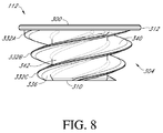
- Figures 8 and 9 show the helical structure 304 in more detail.
- the helical structure 304 includes three spaced apart helical protrusions 332A, 332B, 332C.
- the anchor member 112 has a triple lead configuration.
- Other embodiments can have a single lead (as in the embodiments discussed in connection with Figures 11 and 17 below), a double lead, or a quadruple lead configuration.
- Distal ends of the three helical protrusions 332A, 332B, 332C can be seen in Figure 9 .
- Each of these helical protrusions 332A, 332B, 332C has progressively larger diameter from a distal end to a proximal end thereof in the illustrated embodiment.
- the larger size toward the proximal end enables the helical protrusions to project farther laterally into the faces 218A, 218B, 218C of the arms 128.
- the smaller size toward the distal end enables the disruption of bone toward the distal end to be minimized.
- the helical protrusions can be threads in some embodiment.
- Figure 8 shows distal and proximal faces 336, 340 of one of the helical protrusions.
- the distal face 336 is configured to be advanced along one or guided by one of the helical paths described above.
- the distal face 336 is angled relative to a transverse (e.g., perpendicular) cross-sectional plane of the anchor member 112, which angle may be selected to match the lead surface 152, as discussed above.
- the distal face 336 can slide along the lead surface 152, one of the faces 218A, one of the faces 218B, and one of the faces 218C.
- the proximal face 340 can slide along or be guided by the surface 228B ( Figure 6A ) or another distally-oriented face disposed in one of the arms 128 or on a lower surface of the guide member 148.
- Figure 8 shows that a spiral or helical surface 342 extends between adjacent helical protrusions 332A, 332B, 332C.
- the spiral surface 342 can extend from the base of a distal surface 336 of the helical protrusion 332B to the base of the proximal surface of the helical protrusion 332C.
- the spiral surface 342 has a proximal to distal dimension that is about the same as the proximal-distal dimension of the side surface 214 between the surfaces 218A, 228B (See Figure 6A ).
- the proximal to distal dimension of the spiral surface 342 is about 50 % larger than and in some cases twice as large as the proximal to distal dimension of the helical protrusions 332A, 332B, 332C.
- Figure 2 shows that the anchor member 112 projects into the arms 128 and into a space between the arms when the anchor member and the base member are assembled.
- the anchor member 112 is exposed between the arms 128 when advanced into the base member 108.
- a plurality of elongate segments 352 of the helical protrusions 332A, 332B, 332C are not covered by the faces 218A, 218B, 218C, 222B of the arms 128 but rather are located in an open area between the arms.
- the exposed segments 352 create areas of engagement with the bone that vastly increase the initial pull-out force of the assembly 100 when initially placed. This improved initial pullout force greatly reduces the chance of dislodgement, as discussed below in connection with Figure 26 .
- Some additional unique features of the assembly 100 include helical surfaces in the anchor member 112 that mate only in very small and spaced apart areas of the base member 108 while exposing a majority of the helical surface to allow the exposed areas to be disposed directly in the bone for direct contact therewith.
- a portion of the helical surface is disposed within the arms 128 and not exposed but a majority of the helical surface is exposed to be embedded in bone.
- the percentage of the surface area of the exposed segments 352 to the total area of the helical protrusions 332A, 332B, 332C is between about 80 and 98% in some embodiments.
- the percentage of the area of the exposed segments 352 to the total area of the helical protrusions 332A, 332B, 332C is between about 85 and 95% in some embodiments.
- the percentage of the area of the exposed segments 352 to the total area of the helical protrusions 332A, 332B, 332C is about 91% in some embodiments.
- the ratio of the length of the exposed segments 352 to the total length of the helical protrusions 332A, 332B, 332C is between about 0.8 and about 0.98, e.g., between about 0.85 and about 0.95, e.g., about 0.9 in various embodiments.
- the structure provided herein enables the threads to extend a large distance from the center of the recess 104.
- the lateral extent, e.g., radius of the helical protrusions 332A, 332B, 332C can be at least 50% of the lateral extent, e.g., radius of the peripheral member 140, for example, at least about 50% and/or less than or equal to about 75%.
- the lateral extent of at least one of the helical protrusions 332A, 332B, 332C can be at least about 50%, such as between about 50% and about 55%, of the diameter of the peripheral member 140.
- the lateral extent of at least one of the helical protrusions 332A, 332B, 333C can be at least about 60%, such as between about 60% and about 65%, of the diameter of the peripheral member 140. In some embodiments, the lateral extent of the helical protrusions 332A, 332B, 333C can be at least about 70%, such as between about 70% and about 75%, of the diameter of the peripheral member 140. In certain embodiments, as shown in Figure 8 , the diameter of each of the helical protrusions 332A, 332B, 332C can vary from the proximal face 300 to the distal end 310 of the anchor 112.
- the diameter of a portion of the helical protrusions 332A, 332B, 332C near the proximal face 300 can be greater than the diameter of a portion of the helical protrusions 332A, 332B, 332C near the distal end 310.
- the percentage can be measured against any portion of the protrusions 332A, 332B, 332C.
- the lateral extent of the helical protrusion 332C can be between about 50% and 55% of the diameter of the peripheral member 140, while the lateral extent of the helical protrusion 332A can be between about 70% and 75% of the diameter of the peripheral member 140.
- Figure 7 shows that the proximal face 300 of the anchor member 112 can include a driver interface 364 to facilitate advancing the anchor member 112 into the base member 108.
- the driver interface 364 can take any suitable form, for example, as three spaced apart recesses.
- the recesses can be cylindrical recesses extending into the disc member 312.
- Figures 10A-10H illustrate methods of implanting the humeral shoulder assembly 100 into the humerus H.
- surgical access has been provided to the humerus H and the humerus has been prepared.
- Preparing the humerus H can include cutting off a joint-facing portion of the humeral head h.
- the joint facing portion can be further prepared, for example by providing a countersunk region CS in the exposed face F.
- the countersunk region CS enhances a low profile application of the assembly 100 as discussed further below.
- a pin 400 is placed in a central region of the countersunk region CS.
- Figure 10B shows that the pin 400 may be used to guide a reamer to create a well at the base of the pin.
- Figure 10C shows the well having received a tool 404 that has been advanced into the face F to modify the well to receive the base member 108.
- the tool 404 has a plurality of, e.g., three, radial projections 406 to create channels radiating from the well as shown in Figure 10D .
- the projections 406 have an edge profile similar to that of the arms 128, e.g., with a convex edge from proximal to distal when viewed from the side similar to the edge 210.
- Figures 10D show the expose humeral face F with the pin 400 and tool 404 removed so that a created recess CR in the face F is shown.
- the recess CR is configured to permit the base 108 to be advanced with ease into the face F of the humeral head has shown in Figure 10E .
- the recess CR is shaped to match the shape of a portion of the base member 108 that projects distally.
- Figure 4 shows that the arms 128 can be equally spaced about the base member 108, e.g., outer ends thereof coupled with the peripheral member 140 can be spaced circumferentially by about 120 degrees.
- the arms 128 can be thin at radially outer portions thereof and can be joined adjacent to the distal end 120 of the base member 108. Accordingly, the radial projections of the recess CR created by the radial projections 406 of the tool 404 can be narrow and spaced apart by the same amount as the arms 128, e.g., about 120 degrees apart.
- the projection 406 and corresponding projections of the recess CR are generally straight, radial projections, the projections 406 could be curved and/or can extend away from a central region to in a non-radial direction matching the shape and orientation of any projections of the base member 108.
- the insertion of the base member 108 into the recess CR can be achieved with ease, e.g., without an impactor or any other tools, but rather by hand force.
- the base member 108 advantageously is symmetrical about the axis A (see Figures 4 and 5 ). This allows the surgeon to insert the base member 108 in any orientation provided that the arms 128 and the projections in the recess CR are aligned. Other configurations have a preferred orientation, as discussed further below.
- Figures 10E-10F show that the countersunk region CS is configured to receive the peripheral member 140 in a recessed position.
- the countersunk region CS has a bone recessed area, which is recessed by about the proximal-distal dimension 416 (shown in Figure 6 ) of the peripheral member 140.
- the base member and/or the humeral shoulder assembly 100 can positioned as desired relative to the face F of the humeral head h, e.g., with a small gap or flush mounted.
- Flush-mount enables a joint interface coupled with the assembly 100 to be positioned close to the face F, e.g., with little to no gap therein. Consistent and accurate positioning of the assembly 100 and joint interface can be important factors in properly locating the prosthetic joint interface.
- Figure 10F shows that after the base member 108 has been inserted into the face F of the humerus a subsequent step can involve coupling the guide tool 432 with the base member.
- Figure 25 shows details of one embodiment of the guide tool 432.
- the guide tool 432 preferably includes a guide body 436 disposed at a proximal portion thereof.
- the guide body 436 projects outside and proximally of the base member 108 and is configured to guide the anchor member 112 to be advanced thereover.
- the guide body 436 is a cylindrical member.
- a distal portion 440 of the guide tool 432 is configured to be coupled with the base member 108.
- a threaded distal portion 444 is configured to mate with the threads in the threaded recess 250 (see Figure 6A ).
- a tapered portion 448 facilitates insertion of the guide tool 432 into the cylindrical member 130 of the base member 108. More particularly as shown in Figure 6A , the cylindrical member 130 can be tapered on an inside surface thereof, such that the recess formed in the member 130 is narrower at the distal end than at the proximal end thereof. Stated another way, a wall surrounding the recess in the cylindrical member 130 is closer to the axis A near the threads 250 than near the proximal end of the recess.
- the outside surface of the tapered portion 448 is closer to a central longitudinal axis B of the guide tool 432 than is a proximal portion of the tapered portion 448.
- the tapers match such that if the guide tool 432 is inserted into the cylindrical member 130 with the axis A, B offset, the surface 448 and the inside surface of the recess in the cylindrical member 130 match to align these axes before the threads 444 and the threads in the recess 250.
- Figure 10G shows the anchor member 112 engaged with the base member 108. This configuration results from advancement of the anchor member 112 over the guide tool 432 in one method.
- a method step includes coupling a driver with the driver interface 364 on the proximal face 300 of the anchor member 112.
- the driver can take any suitable form, e.g., can include a plurality of protrusions configured to mate with recesses of the driver interface 364.
- the driver can be configured to snap into or onto the anchor member 112 at the driver interface 364. Embodiments of a driver are discussed below in connection with Figures 16B and 24B .
- the driver has a ratchet mechanism such that the surgeon can continuously hold the tool and need not release the handle to re-grip it to apply additional turns to the anchor member 112.
- one advantage of the three thread design of the anchor member 112 is that less rotation of the anchor member is required as compared to a two thread design or a one thread design to fully seat the anchor member in the base member 108.
- the surgeon observes the face F of the humerus and advances the anchor member 112 until some fluid is observed to emerge from the recess CR and / or around the assembly 100.
- the emergence of fluid suggests that the anchor member 112 is fully seated in the bone in a way providing excellent initial bone retention. Such retention provides enhanced pull-out force.
- Figure 26 illustrates the initial pull-out force 1510 for Embodiment A, a variant of the shoulder assembly 100 in which the anchor member 112 has a single continuous thread. Portions of the helical structure 304 project into the open area defined between the arms 128 and engage the bone thereby increasing the initial pull-out force of the assembly 100 when initially placed. As shown in Figure 26 , the peak force corresponding to the initial pull out force 1510 of Embodiment A is at least ten times greater than the peak force corresponding to the initial pull out force 1500 of the prior art design having a base member and no anchor thread.
- the assembly 100 enables a variety of joint interface components.
- the surgeon can couple an anatomical joint interface with the assembly 100, e.g., by positioning an anchor portion of the anatomical joint interface in the recess 104.
- a reverse shoulder configuration is better for the patient.
- the surgeon can dispose an anchor portion of a reverse configuration shoulder joint interface in the recess 104.
- Figure 10H shows an adaptor 464 coupled with the recess 104.
- the adaptor 464 can be seated with a concave socket portion 468 that can be coupled with a convex head implanted in the scapula in the reverse shoulder configuration.
- the methods described above, e.g., in connection with Figures 10A-10H can include additional steps and employ additional tools as discussed below.
- the shoulder assembly 100 also can be adapted to be compatible with other methods herein, e.g., having a guidewire passage suitable for employing over-the-wire methods discussed below.
- FIG. 11-16C show a stemless shoulder assembly 500 and methods similar to the shoulder assembly 100 and methods discussed above except as described differently below.
- the assembly 500 is configured to allow a guidewire to be used to advance components thereof into a prepared humeral face F, providing for an efficient and accurate procedure.
- the assembly 500 includes a recess 504, a base member 508, and an anchor member 512.
- a thread or other helical protrusion 532 extends from the anchor member 512 into engagement with the base member 508 and into an open area where it can engage bone.
- the anchor member 512 has a single lead configuration.
- Other embodiments can have a multiple lead configuration, e.g., including a double lead, a triple lead, or a quadruple lead configuration.
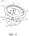
- Figures 12 , 13 and 13A show features of the base member 508 that facilitate delivery of the base member and/or the anchor member 512 over a guidewire.
- the base member 508 has a plurality of arms 528A, 528B, 528C that extend between a distal and a proximal end 520, 524 of the base member 508.
- the arms 528A, B, C are coupled with a sleeve 530 disposed adjacent to the distal end 520 of the base member 508.
- the sleeve 530 has an opening at a proximal end 534 thereof extending into a lumen 538.
- the lumen 538 extends from the opening at the proximal end 534 to an opening at the distal end 520 of the sleeve 530.
- the lumen 538 is accessible through an open space 542 disposed between the arms 528A, B, C and between the proximal end 534 of the sleeve 530 and the proximal end 524 of the base member 508.
- the space 542 provides access to the lumen 538 by a direct path, e.g., a path perpendicular to the plane of the proximal end 524 of the base member 508.
- Figure 12 shows that the base member 508 includes a guide surface 548 and a lead surface 552 in some embodiments.
- the guide and lead surfaces 548, 552 can be regions of a continuous guide member and can be a continuous expanse without a change in orientation between them.
- the guide surface 548 can be substantially flat, e.g., disposed on a plane that is perpendicular to a longitudinal axis C of the lumen 538.
- the lead surface 552 can be angled to match the pitch of the helical protrusion 532 (see Figure 14 ) on the anchor member 512.
- the guide member or the guide and lead surfaces 548, 552 can be disposed adjacent to a periphery of the base member 508, e.g., between a peripheral member 540 and the axis C.
- the guide and lead surfaces 548, 552 are coupled at outer edges thereof with an inner edge of the peripheral member 540.
- a circumferential gap 544 is provided between ends of the guide and lead surfaces 548, 552. The gap 544 is configured to permit the helical protrusion 532 (see Figure 14 ) to be advanced along the lead surface 548 to a top laterally extending surface 560A of the first arm 528A, which is disposed beneath the gap 544.
- Figure 13A show the path from the lead surface 552 to the top surface 560A through the gap 544 is a first segment of a helical path about the axis C.
- a second segment of the helical path extends from the top laterally extending surface 560A to a top laterally extending surface 560B on the arm 528B.
- a third segment of the path extends from the top laterally extending surface 560B to a top laterally extending surface 560C of the arm 528C.
- a fourth segment of the path extends from the top laterally extending surface 560C to a laterally extending surface 564A of the arm 528A below the surface 560A.
- the laterally extending surface 564A is a mid-level surface on the arm 528A.
- the helical path through the base 508 extends in the same manner across a plurality of mid-level surface corresponding to the surface 564A and a plurality of surfaces at a lower level of the arms to a distal end point on or adjacent to or at a laterally extending surface 568C.
- the helical path described above accommodates a single helical protrusion, e.g., thread, of the anchor member 512.
- An advantage of this design is that only a single thread must traverse a gap in the proximal surface of the base portion 508. Also, the thread is much longer than the thread of the anchor member 112 and is generally at a shallower angle and so may be advanceable along the helical path with less torque than is required for the anchor member 112.
- Figures 14 and 15 show further details of the anchor member 512.
- the anchor member 512 has a proximal face 600 having a tapered annular surface.
- the proximal face 600 can include a driver interface 604 that can take any suitable form, such as any of those described above.
- driver interface 604 can include a plurality of recesses.
- Figure 15 shows that the recess 504 can extend from the proximal face 600 to a distal end having an aperture 608 formed therein.
- the aperture 608 can be configured to receive a guidewire such that the anchor member 512 can be advanced over a wire, as discussed further below.
- Figures 16A-C illustrate various methods of implanting the shoulder assembly 500.
- the method can include compatible steps of any of the methods discussed above in connection with Figures 10A-10H , including initial preparation of a humeral head with a recess to receive a guidewire 650.
- the guidewire 650 can take any suitable form and is sometimes known as a Kirschner wire or K-wire.
- the guidewire 650 is placed into a recess extending distally into a face of a humeral head.
- the base member 508 is advanced over the proximal end 654 of the guidewire 650, e.g., an opening at the distal end of the lumen 538 is advanced over the proximal end 654 of the guidewire 650.
- the lumen 538 is sized so that the base member 508 can easily slide along the length of the guidewire 650 to a position corresponding to the position of the base member 108 in Figure 10E .
- the base member 508 is advanced into the bone.
- the base member can be urged into the recess with low force, e.g., with hand force and without impactors or with light force from the impactor.
- the gap 544 is oriented with respect to the anatomy.
- the gap 544 can be disposed at a lower elevation (caudad) compared to the position of the guide surface 548.
- FIG 16B illustrates further step in which a cannulated driver 662 is advanced over the guidewire 650.
- the cannulated driver 662 preferably has an interface configured to mate with the driver interface 604 on the anchor member 512.
- the driver 662 can have a plurality of prongs extending distally therefrom to engage recesses in the face 600 of the anchor member 512.
- the surgeon couples the driver 662 with the anchor member 512. Once so coupled, the driver 662 and the anchor member 512 are advanced over the guidewire 650.
- An initial step of advancing the driver 662 and the anchor member 512 over the guidewire 650 includes inserting the proximal end 654 of the guidewire 650 into the aperture 608 in the anchor member 512. Continued advancement of the driver 662 and the anchor member 512 causes the guidewire 650 to be advanced through the driver 662 and out of a proximal end 668 thereof.
- the distal portion of the helical protrusion 532 is placed against the guide surface 548 and/or the lead surface 552 and through the gap 544 and from there along the helical path discussed above.
- the cannulated driver 662 can be removed leaving the shoulder assembly 500 in place as shown in Figure 16C . Thereafter the guidewire 650 is removed to allow subsequent steps to proceed, including attachment of a joint interface as discussed above.
- the shoulder assembly 500 provides a single sleeve-like structure in the anchor member 512 rather than co-axial sleeve one in each of the base and anchor members.
- the anchor member 512 includes a cylindrical structure.
- the cylindrical structure of the assembly 500 reinforces the helical protrusion 532 and also comprises the recess 504. This provides a simpler construction having fewer components. Also, there is no chance for multiple cylinders to be slid over each other to become misaligned, leading to binding or increased torque requirements for advancing the anchor member 512 into the base member 508.
- FIGS 17-24B illustrate an embodiment of a humeral shoulder assembly 1000 in which distally projecting arms are more rigid by virtue of being coupled to each other and directly to a cylinder member at intermediate positions. This structure retains the direct bone engagement of exposed threads while making the arms more rigid.
- Figure 17 illustrates the assembly 1000 having a base member 1008 and an anchor member 1012.
- the base member 1008 and the anchor member 1012 are separable components that can be applied to the patient separately, e.g., assembled in multiple steps within the bone in techniques similar to those discussed above.
- FIGS. 18-22 illustrate various views of the base member 1008.
- the base member 1008 has a distal end 1020 configured to be embedded in bone and a proximal portion 1024 to be disposed adjacent to the face F of the humerus H or another bone surface.
- the base member 1008 can have a plurality of spaced apart arms 1028 projecting from the proximal portion 1024 to the distal end 1020 of the base member 1008.
- Each arm 1028 can define an outer edge 1210 having an arcuate sloping surface. The sloping surface can facilitate insertion of the base member 1008 into an exposed humeral face F as discussed above in connection with Figures 10A-10H .
- each arm can define an inner edge 1214.
- the inner edge 1214 of a distal portion 1046 of each of the arms can be connected to form the distal end 1020 of the base member 1008 (see Figure 21 ).
- each arm 1208 can include one or more laterally extending recesses 1218A, 1218B, 1218C.
- the number of laterally extending recesses can vary between different arms 1028.
- a first arm can include a first recess 1218A and a second recess 1218B, while a second arm can include only one recess 1218C.
- the recesses 1218A, 1218B of the first arm can be longitudinally displaced from the recess 1218C of the second arm to accommodate a helical structure 1304 of the anchor member 1012 (see Figure 17 ).
- each of the laterally extending recesses 1218A, 1218B, 1218C can be equidistant from the longitudinal axis of the base member 1008 to accommodate an anchor member 1012 having a substantially constant outer diameter along the helical structure 1304 (see Figure 17 ).
- the base member 1008 can also include a central portion (e.g., a cylindrical member 1030).
- the cylindrical member 1030 can include an open proximal end 1034 and a closed distal end 1032.
- the proximal end 1034 can define the proximal-most point of the base member 1008.
- the proximal end 1034 can include an annular groove 1076 ( Figure 18 ) for receiving a c-ring that may be present to prevent loosening between the anchor member 1012 and the base member 1008.
- a c-ring can be part of a locking device, as discussed further in connection with Figures 27-27A below.
- a threaded recess 1250 can be formed in the distal portion of the cylindrical member 1030.
- the threaded recess 1250 enables a component to be advanced into a secure position of engagement with the base 1008.
- the component can be part of a prosthetic joint interface or can be a tool used in placement of the shoulder assembly 1000.
- the recess 1250 can engage a guide tool 432 ( Figure 25 ).
- the guide tool 432 can extend the length of the cylindrical member 1030 to facilitate insertion of the anchor member 1012 into the base member 1008.
- Figure 20 shows that the outer wall of the cylindrical member 1030 can define a helical channel 1050 (e.g., groove or opening).
- the outer wall of the cylindrical member 1030 can connect to the inner edge 1214 of the arms 1028, such that portions of the helical channel 1050 can align with each of the laterally extending recesses 1218A, 1218B, 1218C to form a pathway for the helical structure 1304 of the anchor member 1112 (see Figure 17 ).
- Figure 19 illustrates that the proximal portion 1024 of the base member 1008 can include a peripheral member 1040 disposed about the outer periphery of the proximal portion 1024.
- the peripheral member 1040 can be coupled with the proximal ends of the arms 1028 (see Figure 22 ) to provide a unitary structure.
- the proximal portion 1024 can include a guide member 1048 that can be connected to the peripheral member 1040.
- the guide member 1048 can be partially recessed from the proximal face of the peripheral member 1040 to provide a space into which a proximal disc structure 1312 of the anchor member 1012 can be positioned (see Figure 17 ).
- the guide member 1048 can include a plate-like projection extending radially inwardly from the peripheral member 1040 to a proximal portion of the cylindrical member 1030.
- the guide member 1048 can extend continuously from the inner edge of the peripheral member 1040 to the cylindrical member 1030 around at least about 50% of an inner diameter of the peripheral member 1040.
- the guide member 1048 can extend discontinuously from the inner edge of the peripheral member 1040 to the cylindrical member 1030.
- a gap 1072 can be defined adjacent to but radially inward of an arcuate segment of the guide member 1048 that is disposed between the peripheral portion 1040 and the gap 1072. The gap 1072 facilitates insertion of the anchor member 1012 into the base member 1008.
- the proximal end 1034 of the cylindrical member 1030 can be elevated above the proximal-most aspect of the peripheral member 1040.
- the proximal disc structure 1312 can fill the annular space bounded by the outside surface of the cylindrical member 1030 and the inside surface of the peripheral member 1040 to create a tapered, annular surface from proximal end 1034 of the cylindrical member 1030 to the peripheral member 1040. This structure avoids inflection points in the side profile of the assembly 1000, which is advantageous in reducing or eliminating gaps between the assembly 1000 and another component of a shoulder joint assembly coupled therewith.
- Figure 23 illustrates features of the anchor member 1012, which has a proximal disc structure 1312.
- the proximal disc structure 1312 can define a central opening 1316 that can surround the proximal end 1034 of the cylindrical member 1030 when the shoulder assembly 1000 is assembled.
- the proximal disc structure 1312 can include a driver interface 1364 (e.g. a plurality of openings) for engaging a driving tool 450 (see Figure 24B ). Rotating the driving tool 450 can advance the anchor member 1012 to rotationally engage the base member 1008.
- the anchor member 1012 can also include a continuous helical structure 1304 disposed distally of the proximal disc structure 1312.
- the anchor member 1012 has a single helical structure 1304.
- Other embodiments can have a multiple helices, e.g., including a double helix, a triple helix, or a quadruple helix configuration.
- the inner edge of the helical structure 1304 can define the innermost edge of the anchor member 1012 distal of the disc structure 1312 in that the anchor member 1012 does not include a central body structure. In at least this sense, the anchor member 1012 has an open helix construction.
- the helical structure 1304 defines a substantially constant inner diameter and a substantially constant outer diameter in one embodiment.
- the disc structure 1312 When the shoulder assembly 1000 is assembled, the disc structure 1312 can abut the guide member 1048 of the base member 1008 and the helical structure 1304 can be disposed in the helical groove 1350 and the laterally extending recesses 1218A, 1218B, 1218C of the base member 1008 (see Figure 17 ). Portions of the helical structure 1304 project into the open area defined between the arms 1208 and engage the bone, thereby increasing the initial pull-out force of the assembly 1000 when initially placed. As shown in Figure 26 , the peak force corresponding to the initial pull out force 1520 of the shoulder assembly 1000 is at least five times greater than the peak force corresponding to the initial pull out force 1500 of the prior art.
- Figures 24A-24B illustrate tools that can be used to implant the shoulder assembly 1000 and corresponding methods.
- the method of using the tools can include compatible steps of any of the methods discussed above in connection with Figures 10A-10H including creating a recess CR in the humeral head (see Figure 10D ).
- the base member 1008 can be inserted into the face F of the humerus head h (similar to Figure 10E ).
- the insertion of the base member 1008 can be achieved without an impactor or any other tools, but rather just inserted by hand force.
- a subsequent step can involve coupling the guide tool 432 with the base member 1008 (see Figure 24A ).
- Figure 25 illustrates one embodiment of the guide tool 432.
- the guide tool 432 can extend the length of the cylindrical member 1030 to guide the anchor member 1112 into the base member 1008.
- the method can include coupling a driver 450 with the driver interface 1364 (see Figure 24B ).
- the driver 450 can take any suitable form, e.g., can include a plurality of protrusions configured to mate with openings of the driver interface 1364.
- the driver 450 has a ratchet mechanism such that the surgeon can continuously hold the tool and need not release the handle to re-grip it.
- the methods described above, e.g., in connection with Figures 24A-24B can include additional steps and employ additional tools as discussed above.
- the shoulder assembly 1000 and/or the tool 450 also can be adapted to be compatible with other methods, e.g., with over-the-wire methods.
- the base member 1008 can have a lumen extending through the distal end 1020 to guide the base member into place.
- a channel in the tool 450 can be used in guiding the anchor member 1012 into place in the base member 1008.
- Figures 27-32 show features that can reduce or eliminate disengagement between a base member and an anchor member. These embodiments are illustrated in connection with the shoulder assembly 100, but can be used in connection with any of the embodiments herein. Also, although the features are discussed separately they could be combined in some embodiments.
- Figures 27 and 27A shows a shoulder assembly 1100 that includes a base member 1108, an anchor member 1112, and a locking device 1118 disposed adjacent to a proximal end 1124 of the base member 1108.
- the locking device 1118 comprises a C-ring 1122 that is disposed partially in a recess or groove 1126 (See Figure 27A ) of the anchor member 1112 and partially in a groove 1130 (see Figure 27A ) of the base member 1108.
- Figure 28 shows a partial assembly in which the C-ring 1122 is coupled with the anchor member 1112 prior to coupling the anchor member 1112 to the base member 1108. In the illustrated embodiment, the C-ring 1122 is disposed in the anchor member 1112 prior to implantation.
- Figure 27A shows that the cross-sectional shape of the C-ring 1122 facilitates actuation of the C-ring 1122 during assembly.
- a distal face 1134 of the C-ring 1122 is angled relative to a plane oriented perpendicular to the distal-proximal direction of the assembly 1100.
- the anchor member 1112 is advanced into the base member 1108 until the distal face 1134 engages a proximal portion 1138 (See Figure 27A ) of the base member 1108 and is deflected thereby into or deeper into the recess 1126 of the anchor member 1112. This permits the anchor member 1112 to move relative to the base member 1108 until the C-ring 1122 moves to the position of the groove 1130.
- FIG 27A shows the final position of the C-ring 1122 with a portion disposed in the groove 1130 and a portion disposed in the groove 1126.
- the anchor member 1112 is locked into the base member 1108 because further advancement of the anchor member 1112 into the base member 1108 is prevented by contact between a base face 1148 and an anchor face 1120 and because retraction of the anchor member 1112 from the base member 1108 is prevented by the C-ring 1122 in cooperation with grooves 1126 and 1130 (see Figure 27 ).
- the C-ring 1122 can be coupled with the base member 1108 prior to assembly of the anchor member 1112 with the base member 1108.
- a surface of the anchor member 1112 can be configured to deflect the C-ring 1122 into or deeper into the groove 1130.
- a proximal face of the C-ring 1122 may be angled relative to a plane oriented perpendicular to the distal-proximal direction of the assembly to facilitate deflection of the C-ring.
- a C-ring is illustrated, other structures that can be temporarily deflected into the recess 1126 or the recess 1130 can be used, such as spring loaded or resilient detents or members or other similar structures.
- Figures 29 and 30 illustrate another embodiment of a shoulder assembly 1200 that has a base member 1208, an anchor member 1212, and a locking device 1218 comprising an interface between the anchor member 1212 and the base member 1208.
- the locking device 1218 includes a distal projection 1220 disposed on a distal side of a helical protrusion 1232 (see Figure 30).
- Figure 30 shows that the distal projection 1220 can have a first face 1222 that is oriented generally proximal to distal and a second face 1226 that is disposed at an angle relative to a plane extending perpendicular to the proximal-distal direction of the anchor member 1212.
- the anchor member 1212 is advanced into the base member 1208 in the same manner as described above in connection with the assembly 100.
- the second face 1226 of the projection 1220 approaches a first side 1228A of the arm 1228 of the base member 1208.
- the second face 1226 passes across a lower lateral face of an upper-most slot of the arm 1228.
- local deformation of at least one of the arm 1228 and the projection 1220 permits further advancement of the second surface 1226 relative to the arm until the first surface is disposed on the second side 1228B of the arm 1228 (see Figure 29 ).
- the local deformation is preferably temporary such that the deformed structure(s) return toward their undeformed state(s).
- the first face 1222 abuts a corresponding surface of the second side 1228B of the arm 1228.
- the anchor member 1212 is locked into the base member 1208 because further advancement of the anchor member 1212 into the base member 1208 is prevented by contact between an upper surface of the base member 1208 and an anchor face 1224 and because retraction of the anchor member 1212 from the base member 1208 is prevented by contact between the first face 1222 and the second side 1228B of the arm 1228.
- the locking device 1218 is simple in construction in that a first portion of the interface is disposed on the anchor member 1212 and a second portion of the interface is disposed on the base member 1208 and thus does not require another separable component compared to the shoulder assembly 1100. Also, the locking device 1218 does not require an additional discrete step in the locking of the base member 1208 to the anchor member 1212 because the final step of passing the projection 1220 from the first side 1228A to the second side 1222B is accomplished with the same rotation as is required in connection with the assembly 100, though some additional force may be required to provide the local deformation discussed above.
- Figures 31 and 32 show another embodiment of a shoulder assembly 1300 that has a base member 1308, an anchor member 1312, and a locking device 1318 comprising at least one, e.g., a plurality of deflectable prongs 1320 that can be deployed to span from one of the anchor member 1312 and the base member 1308 to the other of the anchor and base members.
- the spanning of the prong(s) 1320 causes a portion of the prong to be engaged with the base member 1308 and another portion to be engaged with the rotatable anchor member 1312 such that rotation of the anchor member in either direction is reduced or eliminated.
- Figure 31 shows that the prongs 1320 can be disposed on the anchor member 1312 about an inner periphery 1332 of a disc structure 1336 thereof.
- the base member 1308 can have a cylindrical member 1324, similar to that discussed above in connection with the assembly 100.
- the cylindrical member 1324 can have a plurality of scallops or recesses 1328 disposed on a side surface thereof.
- the recesses 1328 can extend entirely around the cylindrical member 1324 in one embodiment to enable the prong(s) 1320 to be engaged at a nearest recess 1328 rather than come precisely to rest at a specific rotational position and recess.
- the base and anchor members 1308, 1312 could be provided with the same number or prongs and recesses, wherein the location of the prongs and recesses are provided at an expected fully engaged position of the anchor member 1312 relative to the base member 1308.
- Figure 31 shows the prong(s) 1320 in a disengaged position. Any suitable technique or tool can be used to deploy the prongs 1320 across a gap between the anchor member 1312 and the base member 1308.
- Figure 32 illustrates a tool 1400 that can be used to deploy the prongs 1320.
- the tool 1400 includes a proximal user grip portion 1404, which can be a cylindrical member or any other ergonomic gripping structure.
- the tool 1400 also includes a plurality of pins 1408 disposed on a distal portion thereof that are configured and positioned to engage driver interfaces 1364 disposed on the proximal face of the disc structure 1336.
- the pins 1408 can be on an opposite side of the tool 1400 from the grip portion 1404.
- the tool 1400 also includes a plurality of prong actuators 1412 disposed on the same side of the tool as are the pins 1408.
- the prong actuators 1412 can each include a first, radially inward side 1416 and a second, radially outward side 1420.
- An angled surface 1424 is disposed between the sides 1416, 1420.
- the angled surface 1424 is configured to engage the prongs 1320 and deflect and in some cases deform them as the tool 1400 is advanced.
- the radially outward side 1420 is configured and positioned to be inserted into a recess 1340 disposed in the proximal faces of the disc 1336 radially outward of the prongs 1320.
- This initial insertion of the prong actuator 1412 into the recess 1340 can be up to a point where the angled surface 1424 first engages the prong 1320.
- the radial distance from the first, radially inward side 1416 to the second, radially outward side 1420 is greater than the radial extent of the recess 1340.
- the radial distance from the first, radially inward side 1416 to the second, radially outward side 1420 spans the recess 1340, the gap between the anchor and base members 1312, 1308 and into the scallop or recess 1328. Further advancement of the tool 1400 causes the angled surface 1424 to engage the prong 1320.
- the prong 1320 to be deflected, e.g., bent or otherwise deformed into the recess 1328 of the base member 1308.
- the prong 1320 spans from the disc structure 1336 of the anchor member 1312 to the recess 1328 of the base member 1308.
- the coupling of the prong 1320 with the base member 1308 causes the anchor member 1312 also to be fixed relative to the bone. This prevents any backing out or unintended disengagement of the anchor member 1312 from the base member 1308.
- one embodiment of the locking device 1318 comprises six prongs 1320.
- one prong 1320 can be provided.
- a plurality of prongs e.g., two three, four, five, twenty, or more prongs 1320 can be provided.
- the prongs 1320 could be disposed on the base member 1308 and could be deflected, e.g., bent or otherwise deformed, into a scallop or recess disposed on the anchor member 1312 in other embodiments.
- the prong 1320 can be configured as a spanning member that need not be formed as a part of either the base member 1308 or the anchor member 1312 but rather as a separate components installed at the proximal side of the assembly 1300.
- the various locking devices discussed herein can be combined to provide multiple locking structures.
- FIGS 33-35 illustrate a humeral implant 1600 and components thereof.
- the humeral implant 1600 includes a stem and that combines the securement benefits of a stem with the securement benefits of the base and anchor member as discussed herein.
- Figures 33 and 34 show the humeral implant 1600 includes a stem 1610.
- the implant 1600 also includes an anchor member 1612.
- the anchor member 1612 is similar to other anchor members discussed above. The description of the features of the other anchor members discussed herein may be combined with or substituted for the features of the anchor member 1612 described below.
- the anchor member 1612 has a proximal face 1614 and a distal threaded portion 1618.
- the distal threaded portion 1618 can have a radially inner edge coupled with a cylindrical portion 1619 of the anchor member 1612.
- a radial outer edge and an expanse between the inner and outer edges of the threaded portion 1618 are adapted to be advanced into and then to be embedded in bone.
- the implant 1600 provides high confidence in securement by combining the engagement between the threaded portion 1618 and the bone matter in the metaphysis with engagement between the distal portion 1636 of the stem 1610 and the bone matter surrounding the canal of the humerus.
- the stem 1610 provides additional securement. See Figure 26 and corresponding discussion for details of securement using such a threaded portion.
- the proximal face 1614 can have a tool interface 1620 that can be engaged by a driver to advance the anchor member 1612 into or remove the anchor member from the stem 1610.
- Figure 34 shows that the proximal face 1614 can be flush with a proximal portion of the stem 1610 when fully advanced. That is, the face 1614 can be positioned so that it does not protrude proximally of a proximal most aspect of the stem 1610, which is discussed further below.
- Figure 33 shows that the proximal face 1614 can be annular, providing an inner edge 1622 that allows access to a portion of the stem 1610 as discussed below.
- the inner edge 1622 can be disposed at the proximal end of the cylindrical portion 1619.
- the cylindrical portion 1619 projects from the inner edge 1622.
- Figure 33 also shows that the proximal face 1614 includes an outer edge 1624 that can be received by and in some cases surrounded by an outer periphery of a proximal portion of the stem 1610.
- the stem 1610 is advantageous in providing multiple modes of securement to a bone, e.g., to a proximal humerus. Compared to the aforementioned stemless designs, the stem 1610 gives a surgeon an option in evaluating a patient to be able to quickly adapt a surgical plan to an implant providing more security or providing security to a different bone segment, such as a canal which may be more robust than the cancellous bone disposed at or just beneath the resection plane.
- Figure 35 shows that the stem 1610 includes a proximal portion 1632 and a distal portion 1636. The distal portion 1636 is configured to be inserted through cancellous bone, for example through a resected humerus of a patient.
- a distal tip 1640 of the distal portion 1636 can be inserted to extend into an intramedullary canal of the humerus.
- the distal portion 1636 includes a central portion 1644 extending proximally from the distal tip 1640, with one or more projections 1648 extending away from the central portion 1624.
- the projections 1648 can include two, three, four or more projections 1648.
- the projections 1648 are evenly spaced around the central portion 1644. For example, if there are three projections 1648, they may be spaced apart by 120 degrees.
- the projections 1648 enable the distal portion 1636 to be inserted into the canal of a long bone, such as a humerus, along thin outer edges of the projections 1348 such that contact with the bone in the canal is initially line contact. This makes insertion of the distal portion 1636 easier because there is less friction between the stem 1610 and the bone. While this provides for relatively minimal surface contact, the anchor member 1612 provides excellent securement, as discussed further below.
- the proximal portion 1632 includes a distal region that can have the same or a similar form to that of a proximal region of the distal portion 1636.
- the distal region of the proximal portion 1632 can have a central portion 1652 and one or a plurality of projections 1656.
- the proximal portion 1632 also can have one or more, e.g., three, projections.
- the stem 1610 is configured such that when implanted in a long bone, e.g. in the humerus, the proximal portion 1632 is disposed in the metaphysis of the bone. That is, the bone may be resected and thereafter, the distal portion 1636 can be advanced into the canal of the humerus, leaving the proximal portion 1632 in the metaphysis.
- the projections 1656 can include similar or the same features discussed above in connection with the arms 128 projection from the proximal end of the anchor member 108.
- the projections 1656 can include lateral spaces to receive and guide the threaded portion 1618 of the anchor member 1612 to the advanced position as shown in Figures 33 and 34 .
- a gap also can be defined between the inner edges of the projections 1656 and an outer surface of the central portion 1652. The gap can accommodate the cylindrical portion 1619 of the anchor member 1612.
- Figure 33 shows that the stem 1610 of the implant 1600 includes a peripheral rim 1660 disposed about, e.g., surrounding the central portion 1652.
- the central portion 1652 can include a cylindrical member that is similar to the cylindrical member 130 in some embodiments.
- the peripheral rim 1660 preferably is coupled with each of the projections 1656.
- the peripheral rim 1660 can be configured to provide structural integrity to the projections.
- the peripheral rim 1660 has a plurality of tool features 1664 disposed about the periphery. In one embodiment, the tool features 1664 include three features equally spaced about the rim. The features can be used to advance the stem 1610 distally into the humerus after the humerus has been resected. In the event the stem 1610 is to be explanted the tool features 1664 can be engaged to dislodge the stem from the humerus.
- the stem 1610 also includes a recess 1666 in which an articular component, such as a glenosphere, can be anchored.
- the recess 1666 is similar to the recess 104 discussed above in certain embodiments.
- the recess 1666 can be disposed in the central portion 1652.
- the central portion 1652 can have a tapered inner surface to provide a Morse taper connection with the articular component.
- a method of implanting the implant 1600 can be similar to those discussed above.
- the humerus can be resected at about the level of the metaphysis. Thereafter, access to the canal of the humerus can be provided or confirmed.
- the stem 1610 can be advanced through the resected surface of the humerus.
- the tip 1640 can be urged through the resection plane and thereafter deeper into the humerus and further into the humeral canal.
- the projections 1648 engage the canal and act to center the distal portion 1636 of the stem in the canal.
- Advancement can be over a wire (in which case stem 1610 can be cannulated) as illustrated above in connection with Figures 16A-16C or freehand.
- stem 1610 can be cannulated
- the surgeon can confirm placement. If appropriate, the surgeon may further advance the stem by impacting the stem into the bone.
- the anchor member 1612 can be advanced into the proximal portion 1632 of the stem as discussed above. For instance, a tool can engage the features 1620 and then apply a torque to engage the thread start(s) of the anchor member 1612 with the thread guiding features of the projections 1656.
- the implant 1600 provides at least two independent modes or zones of securement.
- the implant 1600 is secured in the cancellous bone of the humerus at the methaphysis by the threaded portion 1618 disposed within the proximal portion 1632 of the stem 1610.
- the proximal portion 1632 thus corresponds to one zone of securement.
- This mode and zone of securement are similar to that discussed above in connection with Figure 26 .
- a second mode of securement is provided by the distal portion 1636 of the stem 1610, wherein the stem can integrate with the bone matter surrounding the canal of the humerus.
- the distal portion 1636 thus corresponds to another zone of securement.
- Figures 36-37 illustrate embodiments in which one or more components are at least partially formed by additive manufacturing.
- a structure is assembled from components to create a three dimensional porous metal structure.
- the structure is formed by applying or creating individual layers that are later joined together through a suitable process, such as sintering.
- the layers can be laid down to progressively to form the three dimensional structure.
- Figure 36 shows a humeral implant 1700 including a base member 1708, an anchor member 1712, and a humeral head 1714.
- one or more features of the anchor member 1712 are formed by a process of additive manufacturing.
- the spaced apart arms or projections 1728 of the anchor member 1708 and other structures that interact with the bone may be comprised of a unitary or monolithic porous titanium (Ti-6Al-4V).
- a bottom surface of a peripheral rim 1740 can be formed by additive manufacturing.
- the arms 1728 and/or the distal side of the rim 1740 can have a porous titanium structure that contacts a bone, e.g., a resected portion of the humerus.
- Porous titanium has a modulus similar to bone or of about 2.6 GPa. Matching the modulus of the porous titanium to the bone may enable better stress transfer from the implant to the bone, reducing wear on the bone, and increasing strength at the bone/implant interface.
- the porous titanium structure can have a pore size from about 300 to about 800 ⁇ m, in embodiments from about 350 to about 750 ⁇ m, and in further embodiments from about 400 to about 700 ⁇ m.
- the porosity of the porous titanium structure may be optimized per implant geometry and anatomy and can be about 50%, 55%, 60%, 65%, 70%, 75%, and 80% porous.
- Porous titanium can be formed by an additive manufacturing process, including a 3 dimensionally (3-D) printing process where layers of titanium are formed to create a three dimensional structure.
- the initial layer or layers are formed by such a method directly onto a portion or surface of the anchor member 1708.
- the 3-D printing process includes direct metal laser sintering onto the implant, more specifically, the anchor member 1708.
- blanks are formed by sintering titanium powder with a laser directly onto the substrate or anchor member.
- the blanks are machined, constructed or shaped to create a specific geometry of the bone-engaging surface.
- the blanks are shaped to create either a stemless implant (as in Figure 36 ) or an implant with a stem that can couple with the anchor member discussed herein (as in Figure 37 ).
- a stemless implant as in Figure 36
- an implant with a stem that can couple with the anchor member discussed herein (as in Figure 37 ).
- the 3-D process is used herein to create stemmed or stemless members for implantation in the metaphysis and/or the canal of the humerus
- other portions and surfaces of the implants may be formed with porous titanium, and are within the scope of this disclosure, including, but not limited to the anchor member or peripheral screws or portions thereof, central posts, and other structures that may be combined therewith.
- the porous structure and the solid substrate of baseplate comprise a monolithic, or one-piece structure.
- Electron Beam Melting EBM can be used to 3-D print a porous three dimensional structure on the implant.
- FIG 37 shows a humeral implant 1800 that is a modified embodiment of the humeral implant 1600.
- the implant 1800 includes an anchor member 1812 and a stem 1810.
- the stem 1810 includes a porous substrate 1814 that is disposed over a portion thereof.
- the porous substrate is formed by additive manufacturing, e.g., 3-D printing as discussed above.
- the porous substrate 1814 can extend over a proximal portion of the stem 1810.
- the porous substrate can be disposed over the metaphyseal bone contacting surfaces of the portion of the base not embedded in a canal of the humerus in use.
- the proximal portion that is porous titanium can include some or all of a plurality of projections 1856.
- the proximal portion that is porous titanium also can include some or all of a peripheral rim 1860, e.g., a distal bone engaging side of the rim 1860.
- the porous titanium substrate can also extend distally of the projections 1856 to a location at or just distal of the narrowing of the metaphysis.
- a kit in one embodiment, includes a stemless humeral implant, such as the humeral shoulder assembly 100, and a stemmed humeral implant such as the implant 1600 or the implant 1800.
- a clinician can quickly adapt during a procedure from a stemless approach to a stemmed approach. For example, if the bone is not strong enough to support a stemless implant, the stemmed implant can be used without significant delay or use of much different components.
- the anchor member 112 could be used with either stem or stemless implants.
- some kits can include a variety of sizes of one or both of the stemless implant or the stemmed implant.
- the base member 108 can come in different sizes to occupy an appropriate volume of the metaphysis of the specific humerus that is being treated by the surgeon.
- the stem 1610 or the stem 1810 can be provided in a number of sizes such that the distal ends thereof reaches an appropriate depth in the canal of the humerus and/or fits in the canal with little or no preparation of the bone around the canal.
- proximal and distal shall be defined from the perspective of the humeral shoulder assembly.
- distal refers the direction of the end of the humeral shoulder assembly embedded in the humerus
- proximal refers to the direction of the end of the humeral shoulder assembly facing the glenoid cavity.
- the terms “approximately,” “about,” and “substantially” as used herein represent an amount close to the stated amount that still performs a desired function or achieves a desired result.
- the terms “approximately”, “about”, and “substantially” may refer to an amount that is within less than 10% of, within less than 5% of, within less than 1% of, within less than 0.1% of, and within less than 0.01% of the stated amount.
- the terms “generally parallel” and “substantially parallel” refer to a value, amount, or characteristic that departs from exactly parallel by less than or equal to 15 degrees, 10 degrees, 5 degrees, 3 degrees, 1 degree, 0.1 degree, or otherwise.
Abstract
Description
- The present disclosure relates to stemmed and stemless humeral components of a shoulder joint prosthesis.
- In a shoulder joint, the head of the humerus interacts with the glenoid cavity of the scapula in a manner similar to a "ball and socket" joint. Over time, it may become necessary to replace the shoulder joint with a prosthetic shoulder joint including a humeral component.
- Traditionally, the humeral component is a single body implant having a humeral head and a stem. The stem is configured to be inserted into an intramedullary canal of the humerus. In certain cases, insertion of the stem disadvantageously requires bone to be removed to fit the stem to the canal due to patient-to-patient anatomical variation. Another disadvantage of this approach is that integration of the stem into the bone through a natural process of bone ingrowth can make it difficult to remove the humeral component if it becomes necessary to replace the humeral component with another device. Even when no removal was expected, this approach had the disadvantage of only achieving implant security after sufficient time had passed to allow for sufficient bone ingrowth.
- A stemless humeral component may be used to address some of the disadvantages of conventional humeral components. Stemless humeral components can decrease the amount of bone loss in preparing the humerus to receive the component and decrease the complexity of the joint replacement procedure.
- Stemless humeral component designs can be more challenging to secure to the humerus. Conventional stemless designs rely on bone ingrowth for strength. While such designs perform well over time, there is a risk in the early days and weeks after surgery where such ingrowth has not yet occurred that the stem and stemless humeral component will be dislodged from the humerus. Dislodgement may also occur due to excessive wear, forces applied thereto during a revision surgery or other high load conditions.
- Accordingly, there is a need for a stemless humeral component or prosthesis designed to preserve bone in initial implantation while enhancing initial pull-out resistance. Preferably enhanced initial dislodgement resistance will also provide excellent long term fixation.
- The present disclosure relates to various embodiments of a stemless humeral shoulder assembly that can minimize bone loss and provide excellent initial pull-out resistance and long term fixation. Advantageously, the humeral shoulder assemblies described herein provide adequate compression, increase rotational and longitudinal stability, and encourage bone ingrowth.
- Certain aspects of the disclosure are directed toward a prosthesis mounting system having a base member adapted to be driven into bone. The base member can include a central portion having a lumen extending along a longitudinal axis and a peripheral portion connected to the central portion. Further, the prosthetic mounting system can include an anchor having an inner passage sized to be advanced along the longitudinal axis of the base member. The anchor can have at least one thread surrounding the inner passage. When the anchor is coupled with the base member, the thread extends outward of the central portion of the base member.
- In one embodiment, a stemless humeral shoulder assembly is provided. The assembly includes a base member and an anchor member. The base member has a distal end that can be embedded in bone and a proximal end that can be disposed at a bone surface. The base member has a plurality of spaced apart arms projecting from the proximal end to the distal end. The anchor member is advanceable into the base member to a position disposed within the arms. The anchor member is configured to project circumferentially into the arms and into a space between the arms. The anchor member is exposed between the arms when advanced into the base member. The assembly includes a recess projecting distally from a proximal end of the anchor member to within the base member. The recess is configured to receive a mounting member of an anatomical or reverse joint interface.
- In another embodiment, a humeral shoulder assembly is provided that includes a stem and an anchor. The stem has a proximal region to be disposed in the metaphysis of a humerus, a distal end configured to be disposed in a canal of a humerus and a proximal end. The proximal end is to be disposed at a bone surface. The proximal region of the stem has a plurality of spaced apart projections disposed adjacent to the proximal end. The anchor is advanceable into the stem to a position disposed within the projections. The anchor is configured to project circumferentially into the projections and into a space between the projections. The anchor is exposed between the projections when advanced into the stem. The humeral shoulder assembly includes a recess that projects distally from a proximal end of the anchor to within the stem. The recess is configured to couple with an articular component.
- In another embodiment, a prosthesis mounting system is provided that includes a stem and an anchor. The stem is adapted to be driven into bone. The stem has a central portion that includes a lumen. The lumen extends along a longitudinal axis. A peripheral portion of the stem is connected to the central portion. The stem extends distally of the central portion. The anchor has an inner passage sized to be advanced along the longitudinal axis. The anchor having at least one thread surrounding the inner passage. When the anchor is coupled with a proximal portion of the stem, the thread extends outward of the central portion of the base member.
- Certain aspects of the disclosure are directed toward methods for treating a shoulder joint. The methods can include accessing a humeral head, resecting the humeral head, driving a base member into the humeral head, and advancing an anchor member into the base member. When the anchor member is advanced into the base member, a lateral projection of the anchor member can be disposed through the base member and can be embedded in bone adjacent to the base member. In certain aspects, the methods can also include securing a joint interface to the base member and/or the anchor member.
- In another method for treating a shoulder joint, an end portion of a humerus is accessed. A stem is driven into the end portion of the humerus such that a portion of the stem extends into a canal of the humerus. An anchor member is advanced into the stem such that a lateral projection thereof is disposed through the stem and is embedded in bone adjacent to the stem. A joint interface is secured to the stem and/or the anchor member.
- As described above, in certain aspects the stemless humeral component can be modular to provide more options for the surgeon during a revision surgery. For example, the modular humeral component can include a stemless fixation component adapted to be secured in the head of the humerus and a spherical head removably attached to the fixation component. During the revision surgery, the modular approach can make it easier to convert an anatomic shoulder prosthesis to a reverse shoulder prosthesis.
- In any of the above-mentioned aspects, the anchor member can include a helical structure advanceable to engage corresponding surfaces of the arms. In certain aspects, the anchor can include a cylindrical sleeve and the helical structure can include at least one thread (e.g., one thread, two threads, three threads, or four threads) projecting laterally therefrom.
- Any feature, structure, or step disclosed herein can be replaced with or combined with any other feature, structure, or step disclosed herein, or omitted. Further, for purposes of summarizing the disclosure, certain aspects, advantages, and features of the inventions have been described herein. It is to be understood that not necessarily any or all such advantages are achieved in accordance with any particular embodiment of the inventions disclosed herein. No aspects of this disclosure are essential or indispensable.
- These and other features, aspects and advantages are described below with reference to the drawings, which are intended to illustrate but not to limit the inventions. In the drawings, like reference characters denote corresponding features consistently throughout similar embodiments. The following is a brief description of each of the drawings.
-
Figure 1A is a perspective view of one embodiment of a stemless humeral shoulder assembly shown mounted in a humerus; -
Figure 1B is a cross-sectional view ofFigure 1A , showing the stemless humeral shoulder assembly disposed in the humeral head; -
Figure 2 is a perspective view of the stemless humeral shoulder assembly ofFigures 1A and1B ; -
Figure 3 is an exploded view of the stemless humeral shoulder assembly ofFigure 2 ; -
Figure 4 is a top view of the base member of the shoulder assembly ofFigure 2 ; -
Figure 5 is a first side view the base member ofFigure 4 ; -
Figure 6 is a second side view of the base member ofFigure 4 ; -
Figure 6A is a cross-section of the base member shown inFigure 6 throughline 6A-6A inFigure 4 ; -
Figure 7 is a top perspective view of an anchor member of the shoulder assembly ofFigure 2 ; -
Figure 8 is a side view of the anchor member ofFigure 7 ; -
Figure 9 is a bottom view of the anchor member ofFigure 7 ; -
Figures 10A-10H illustrate steps of various methods of implantation of the stemless humeral shoulder assembly ofFigure 2 ; -
Figure 11 is a top perspective view of another embodiment of a stemless humeral shoulder assembly; -
Figure 12 is a top perspective view of a base member of the stemless humeral shoulder assembly ofFigure 11 ; -
Figure 13 is a top view of the base member ofFigure 12 ; -
Figure 13A is a side view of the base member ofFigure 12 ; -
Figure 14 is a top perspective view of an anchor member of the stemless humeral shoulder assembly ofFigure 11 ; -
Figure 15 is a top view of the anchor member ofFigure 14 ; -
Figures 16A-16C illustrate steps of various methods of implantation of the stemless humeral shoulder assembly ofFigure 11 ; -
Figure 17 is a top perspective view of another embodiment of a stemless humeral shoulder assembly; -
Figure 18 is a top perspective view of a base member of the stemless humeral shoulder assembly ofFigure 17 ; -
Figure 19 is a top view of the base member ofFigure 18 ; -
Figure 20 is a side view of the base member ofFigure 18 ; -
Figure 21 is a bottom view of the base member ofFigure 18 ; -
Figure 22 is a cross-sectional view of the base member ofFigure 19 along line 22-22; -
Figure 23 is a top perspective view of an anchor member of the stemless humeral shoulder assembly ofFigure 17 ; -
Figures 24A-24B illustrate tool and component combinations that can be provided in various methods of implantation of the stemless humeral shoulder assembly ofFigure 17 ; -
Figure 25 illustrates an adaptor or centering pin that can be used to align a driver with a base member, as discussed herein; -
Figure 26 illustrates the performance of various embodiments of stemless humeral shoulder assemblies; -
Figure 27 is a cross-sectional view of another embodiment of a shoulder assembly having a locking device disposed between a base member and an anchor member thereof to reduce or eliminate disengagement of the anchor member from the base member; -
Figure 27A is an enlarged view of the locking device shown inFigure 27 taken through line 27A-27A; -
Figure 28 is a top perspective view of an anchor member assembly of the shoulder assembly ofFigure 27 ; -
Figure 29 is a side view of a shoulder assembly having another embodiment of a locking device; -
Figure 30 is a side view of an anchor member of the shoulder assembly ofFigure 29 ; -
Figure 31 is a top view of a shoulder assembly having another embodiment of a locking device; and -
Figure 32 is a bottom perspective view of a tool for actuating a locking structure of the locking device of the shoulder assembly ofFigure 31 from a disengaged configuration to an engaged configuration. -
Figures 33 and 34 are a top perspective and side views of a humeral implant including the anchor member. -
Figure 35 is a side view of a stem of the humeral implant ofFigure 33 without anchor member. -
Figure 36 is a view showing the components of a stemless humeral implant having one or more surfaces formed by additive manufacturing. -
Figure 37 is a top perspective view of another embodiment of a humeral implant with a stem, at least a portion of the implant being formed by additive manufacturing. - While the present description sets forth specific details of various embodiments, it will be appreciated that the description is illustrative only and should not be construed in any way as limiting. Furthermore, various applications of such embodiments and modifications thereto, which may occur to those who are skilled in the art, are also encompassed by the general concepts described herein. Each and every feature described herein, and each and every combination of two or more of such features, is included within the scope of the present invention provided that the features included in such a combination are not mutually inconsistent.
-
Figure 1A shows ahumeral shoulder assembly 100 that has been implanted in an exposed face F of a humerus H. Theassembly 100 has arecess 104 in which further components of a prosthetic shoulder joint can be secured. The configuration of the assembly including therecess 104 enable the humerus H and a corresponding scapula to be fitted with either an anatomical shoulder or a reverse shoulder configuration either initially or as part of a revision procedure.Figure 1B shows that in certain applications, theshoulder assembly 100 can be fully retained within a head h of the humerus H. In other words, the distal-most portion of theassembly 100 is disposed in the humeral head h. Theassembly 100 does not have members that protrude beyond the head h into the intramedullary canal. This arrangement is less invasive and simplifies the procedure compared to a procedure involving a humeral component with a stem, as discussed elsewhere herein. -
Figures 2-9 elaborate on advantageous structures and variations of theshoulder assembly 100 that can be employed in the stemless approach ofFigures 1A-1B . Methods of using theshoulder assembly 100 are discussed below in connection withFigures 10A-10H . Shoulder assemblies capable of being at least partly delivered over a guide wire are discussed below in connection withFigures 11-16C .Figures 17-24B illustrate shoulder assemblies where a joint interface mounting platform or recess is disposed on a base member and an anchor member is provided primarily or solely for bone securement function.Figure 25 shows an adaptor that can be used in connection with several embodiments and methods of applying shoulder assemblies.Figure 26 illustrates the performance of certain embodiments compared to a prior art design. While incremental differences in these embodiments and methods are discussed below, it is to be understood that features of each embodiment can be combined with features of the other embodiments, as appropriate. -
Figures 2 and3 show more detail of components of theshoulder assembly 100 that among other features and advantages provides an anchor member with an inwardly positioned cylindrical member that reinforces outwardly positioned helical structures as discussed below. - The
assembly 100 has abase member 108 and ananchor member 112.Figure 3 shows that thebase member 108 andanchor member 112 are separable components that can be applied to the patient separately, e.g., assembled in multiple steps within the bone as discussed below. Thebase member 108 has adistal end 120 and aproximal end 124. Thedistal end 120 is configured to be embedded in the head of a humerus. Theproximal end 124 is configured to be disposed adjacent to a face of the humerus or another bone surface. Thebase member 108 has a plurality of spaced apartarms 128 projecting from theproximal end 124 to thedistal end 120. Thebase member 108 also has a central portion, e.g., acylindrical member 130, that forms part of therecess 104, as discussed in more detail below. In the illustrated embodiment, thearms 128 are equally spaced about thecylindrical member 130. Thearms 128 can be spaced apart by about 120 degrees. Thebase member 108 and the other base members discussed below can have three arms. Thebase member 108 and the other base members discussed below can have one or a plurality ofarms 128. In various embodiments, thebase member 108 and the other base members discussed below can have two, three, four, five, or six arms. Thearms 128 preferably are thin in the circumferential direction such that large gaps are provided between the arms. -
Figures 3 and4 show theproximal end 124 of thebase member 108 in more detail. In particular, theproximal end 124 can include aperipheral member 140 disposed about the outer periphery of theproximal end 124. Theperipheral member 140 can be coupled withproximal ends 144 of the arms 128 (seeFigures 5-6A ) to provide a unitary structure. In one embodiment, theperipheral member 140 comprises anannular structure 145 that is tapered such that aconvex surface 146 is provided between proximal and distal portions of theperipheral member 140. Theconvex surface 146 extends from a bone engaging side of theperipheral member 140 to a proximal side of theperipheral member 140. The proximal side of theperipheral member 140 is disposed adjacent to but may be spaced from another joint component, such as a portion of an assembly including an anatomical or reverse shoulder joint humeral interface. - In one embodiment, the
proximal end 124 can include a plurality ofguide members 148 that can be coupled with theperipheral member 140. Theguide members 148 can include plate-like projections extending radially inwardly from an arcuate segment of theperipheral member 140. Theguide members 148 can be coupled with, attached to or a monolithic extension of an inner edge of theperipheral member 140. In one embodiment, thebase member 108 includes threeguide members 148. Theguide members 148 can include an angled orlead surface 152 that is angled relative to a transverse plane of theproximal end 124. As used in this context, a transverse plane of theproximal end 124 is a plane that extends perpendicular to a longitudinal axis A (seeFigures 5 and6A ) of thecylindrical member 130. The angle of thelead surface 152 is selected to match the angle of a distal face of a helical structure of theanchor member 112 as discussed further below in connection withFigure 6A and8 . - In one embodiment, each of the
guide members 148 includes aflat surface 156. Each of theflat surfaces 156 can be disposed on a transverse plane of theproximal end 124. Theflat surfaces 156 can extend between anouter portion 160 coupled with theperipheral member 140 and aninner portion 168 disposed adjacent to thecylindrical member 130. In the illustrated embodiment, eachinner portion 168 of threeguide members 148 is spaced from thecylindrical member 130 by acorresponding gap 172. Thegaps 172 partly define an annular volume (projecting distally into the page inFigure 4 ) in which a cylindrical portion of the anchor member can be disposed, as discussed further below. -
Figure 3 shows that theflat surface 156 can be disposed at an elevation distal of (or below) the proximal-most aspect of theperipheral member 140. The distance between the proximal-most aspect of theperipheral member 140 and theflat surface 156 can provide a space into which at least a portion of theanchor member 112 can be recessed. In one embodiment, aproximal end 180 of thecylindrical member 130 is disposed at about the same elevation of the proximal-most aspect of theperipheral member 140. In some embodiments, an outside surface of thecylindrical member 130 and an inside surface of theperipheral member 140 define side surfaces of an annular space into which a proximal portion of theanchor member 112 can be received.Figure 2 shows that the annular space bounded by the outside surface of thecylindrical member 130 and the inside surface of theperipheral member 140 provides a substantially flush, e.g., stepless, profile or transition from the inner and proximal-most aspect of theperipheral member 140 to anouter periphery 182A of theanchor member 112 and from aninner periphery 182B of the anchor member to theproximal end 180 of thecylindrical member 130. The flush profile enables other components of a shoulder joint to be drawn down adjacent to but preferably spaced from theassembly 100. -
Figure 4 shows that theguide members 148 generally are spaced apart byarcuate openings 192. Theopenings 192 extend from a lower end of one of theangled surfaces 152 to an end of anadjacent guide member 148. As discussed further below, theopenings 192 permit laterally extending portions of theanchor member 112 to be advanced into thebase member 108. In certain embodiments, the laterally extending projections include one or more, e.g., three, threads that can be advanced through the openings to engage with thebase member 108 at a position distal of theguide members 148.Figure 4 shows that thearms 128 are disposed distal of but accessible through theopenings 192. Thearms 128 are located at a circumferential position between theangled surface 152 of afirst guide member 148 and a non-angled surface of asecond guide member 148, where the second guide member is adjacent to the first guide member. Preferably, the circumferential position of thearms 128 is closer to the circumferential position of the non-angled surface of thesecond guide member 148 as shown. In this context, the circumferential position is determined by projecting these structures to the plane upon which thenon-angled surface 148 is disposed.Figure 6A shows that a proximal portion of thearms 128 is located distal of the distal-most aspect of theangled surface 152. -
Figure 6A shows one of thearms 128 in more detail. In some embodiments, thearms 128 are each identical. In other embodiments, the arms differ from each other. For example, in the single thread configurations ofFigures 11 and17 the arms differ from each other in having slots advanced distally from a first arm to a next arm in the direction of rotation of an anchor member to accommodate the path of the helical member or thread, as discussed below in connection with those embodiments. Thearms 128 have a plurality ofslots 202, e.g., three slots disposed between proximal and distal ends thereof.Figure 6A shows that theproximal-most slot 202 can be different from the twoslots 202 disposed distal thereof in that theproximal-most slot 202 is bounded by alower surface 218A discussed below but not by a corresponding upper edge formed in thearm 128. As noted above, thearm 128 is coupled with theperipheral member 140 at aproximal end 144 of thearm 128. In one embodiment, a unitary structure is provided. In such a structure, a continuous structure can be provided from within theperipheral member 140 to within a proximal portion of thearm 128 so that there are no welds or joining lines or boundaries in this area. Such an arrangement simplifies the structure and eliminates potential areas for concentration of stress and potentially failure. - An
outer edge 210 of thearms 128 provides a continuously arcuate sloping surface in one embodiment. The sloping surface can facilitate insertion of thebase member 108 into an exposed humeral face F as discussed above and further below in connection withFigures 10A-10H . Aninner edge 214 of thearm 128 can include one or a plurality of, e.g., three, laterally extending faces orsurfaces - The angle of the
surfaces anchor member 112 along a helical path. For example, initial advancement of a lateral portion of theanchor member 112 can cause a leading edge surface of theanchor member 112 to slide along thesurface 152 shown inFigure 6A . Continued advancement can cause the leading edge surface of theanchor member 112 to approach and then slide across thesurface 218A shown inFigure 6A . Continued advancement can cause the leading edge surface of theanchor member 112 to approach and then slide across asurface 218B of anarm 128 disposed adjacent to and on a first side of thearm 128 shown inFigure 6A . Continued advancement can cause the leading edge surface of theanchor member 112 to approach and then slide across asurface 218C of anarm 128 disposed adjacent to and on a second side of thearm 128 shown inFigure 6A . Once theanchor member 112 slides across thesurface 218C of eacharm 128, theanchor member 112 can continue to rotate an additional 5-15 degrees to further compress the entire construct into the bones. Advancement is complete when a proximal face of the threads 340 (seeFigure 8 ) contacts anupper surface Figure 6A ). - At least some of the
surfaces arms 128. For example, thesurface 218B extends laterally outwardly from theinner edge 214 of thearms 128. Acorresponding surface 222B can extend outwardly from theinner edge 214 adjacent to thesurface 218B. Thesurfaces surfaces anchor member 112 discussed below. In these embodiments both of thesurfaces anchor member 112. Theface 222B can have an angled surface similar to that of thesurface 218B. For example, the angle of theface 222B can be the same angle as that of theface 218B. - In one embodiment, each of the
faces distal-most face 218C can have the shortest length. Theproximal-most face 218A can have the longest length. Aface 218B disposed between the distal- and proximal-most faces 218C, 218A can have an intermediate length. These lengths can correspond to the tapered profile of thebase member 108, e.g., with thearms 128 having a generally convex shape from proximal to distal as viewed from the side. The lengths of thefaces anchor member 112, which is some embodiments may be tapered. - In one embodiment, the
proximal-most face 218A does not have a corresponding face on thearm 128 disposed proximal thereof. A lower surface of theguide member 148 disposed adjacent to but clockwise of thearm 128 can abut a proximal side of a thread while a distal side of the thread advances along theface 218A. In this sense, each of thefaces anchor member 112 as discussed further below. - In the embodiment of
Figures 1-10H , each arm has a plurality of, e.g., threefaces face 218A of each of thearms 128 is disposed at the same elevation as thecorresponding face 218A ofadjacent arms 128. Theface 218B of each of thearms 128 is disposed at the same elevation as thecorresponding face 218B ofadjacent arms 128. Theface 218C of each of thearms 128 is disposed at the same elevation as thecorresponding face 218C ofadjacent arms 128. This construction defines a plurality of helical paths on thebase 108 for guiding helical members, as appropriate for certain embodiments. Other embodiments have different helical paths, such as a single path as discussed below in connection with the embodiments ofFigures 11 and17 . Rather, a plurality of spaced-apart surfaces reside on and/or define the helical path. In one right-hand configuration, a first helical path is defined by aface 218A of afirst arm 128, aface 218B of asecond arm 128 adjacent to but disposed clockwise of (as defined above) the first arm, and aface 218C of athird arm 128 adjacent to but disposed counter-clockwise of (as defined above) the first arm. In one embodiment, the first helical path also includes thelead surface 152 disposed above and circumferentially between the first andthird arms 128. A second helical path can extend from asurface 152 to thesecond arm 128 to aface 218C of thefirst arm 128. A third helical path can extend from asurface 152 of thethird arm 128 to aface 218C of thesecond arm 128. Each of the surfaces on the helical paths can have substantially the same angle relative to a transverse plane of thebase 108. In some embodiments, the angle of thefaces - In other embodiments of the
base member 108, three left-handed helical paths can be provided, each one commencing with an oppositely oriented surface similar to thesurfaces 152 and traversing counter-clockwise to aface 218A below and on thearm 128 immediately counter-clockwise of the oppositely oriented surface, then to theface 218B on thenext arm 128 and then to theface 218C on thenext arm 128. In this context, the "next arm 128" is the arm circumferentially spaced from and immediately counter-clockwise of the arm from which the path extends. - Unlike a conventional mating screw structure, only very small segments of the helical path involve contact between the
faces assembly 100 is disposed in the bone. -
Figure 5 shows that agap 232A is provided between theinner edge 214 and thecylindrical member 130 below theface 218A. Agap 232B is provided between theinner edge 214 and thecylindrical member 130 below theface 218B. Agap 232C is provided between theinner edge 214 and thecylindrical member 130 below theface 218C. Thegap 232C is substantially the same width as thegaps gaps gap 172. Thegaps anchor member 112 as discussed further below. Thegap 232C enables a distal portion of theanchor member 112 to be advanced distal of theface 218C. -
Figure 6A shows that in some embodiments, thecylindrical member 130 has a threadedrecess 250 formed in a lower portion thereof. The threadedrecess 250 enables a component to be advanced into engagement with thebase member 108. The component can be another component of a prosthetic joint or can be a tool used in placement of one or more components of theshoulder assembly 100. Therecess 250 can engage a guide tool 432 (seeFigure 25 ) in one technique, discussed in more detail in connection withFigure 10F . -
Figures 2 and7-9 illustrate features of theanchor member 112 which, as discussed above, is advanceable into thebase member 108 to a position disposed within thearms 128. Theanchor member 112 includes aproximal face 300, ahelical structure 304 disposed distally of theproximal face 300, and acylindrical sleeve 308 configured to be disposed around therecess 104. In some embodiments, thesleeve 308 is configured to be advanced over and receive thecylindrical member 130 as discussed further below. - The
proximal face 300 comprises the proximal side of adisc structure 312 disposed at the proximal end of theanchor member 112. Thedisc structure 312 is configured to be disposed in a space partly bounded by theflat surfaces 156, the inner face of theperipheral member 140, and the outer face at theproximal end 180 of thecylinder member 130 of the base member 108 (seeFigure 3 ). Thedisc structure 312 can have a thickness (proximal-to-distal distance) substantially the same as the distance from theflat surfaces 156 to the proximal most aspect of theperipheral member 140. Theanchor member 112 is configured such that regions 320 (Figure 9 ) of the distal surface of thedisc structure 312 are advanced into a position to abut theflat surfaces 156 of thebase member 108 when theshoulder assembly 100 is assembled. -
Figures 8 and9 show thehelical structure 304 in more detail. In one embodiment, thehelical structure 304 includes three spaced aparthelical protrusions anchor member 112 has a triple lead configuration. Other embodiments can have a single lead (as in the embodiments discussed in connection withFigures 11 and17 below), a double lead, or a quadruple lead configuration. Distal ends of the threehelical protrusions Figure 9 . Each of thesehelical protrusions faces arms 128. The smaller size toward the distal end enables the disruption of bone toward the distal end to be minimized. The helical protrusions can be threads in some embodiment. -
Figure 8 shows distal andproximal faces distal face 336 is configured to be advanced along one or guided by one of the helical paths described above. Thedistal face 336 is angled relative to a transverse (e.g., perpendicular) cross-sectional plane of theanchor member 112, which angle may be selected to match thelead surface 152, as discussed above. For example, thedistal face 336 can slide along thelead surface 152, one of thefaces 218A, one of thefaces 218B, and one of thefaces 218C. Theproximal face 340 can slide along or be guided by the surface 228B (Figure 6A ) or another distally-oriented face disposed in one of thearms 128 or on a lower surface of theguide member 148. -
Figure 8 shows that a spiral or helical surface 342 extends between adjacenthelical protrusions distal surface 336 of thehelical protrusion 332B to the base of the proximal surface of thehelical protrusion 332C. The spiral surface 342 has a proximal to distal dimension that is about the same as the proximal-distal dimension of theside surface 214 between thesurfaces 218A, 228B (SeeFigure 6A ). The proximal to distal dimension of the spiral surface 342 is about 50 % larger than and in some cases twice as large as the proximal to distal dimension of thehelical protrusions -
Figure 2 shows that theanchor member 112 projects into thearms 128 and into a space between the arms when the anchor member and the base member are assembled. Theanchor member 112 is exposed between thearms 128 when advanced into thebase member 108. More specifically, a plurality ofelongate segments 352 of thehelical protrusions faces arms 128 but rather are located in an open area between the arms. The exposedsegments 352 create areas of engagement with the bone that vastly increase the initial pull-out force of theassembly 100 when initially placed. This improved initial pullout force greatly reduces the chance of dislodgement, as discussed below in connection withFigure 26 . - Some additional unique features of the
assembly 100 include helical surfaces in theanchor member 112 that mate only in very small and spaced apart areas of thebase member 108 while exposing a majority of the helical surface to allow the exposed areas to be disposed directly in the bone for direct contact therewith. In some embodiments, a portion of the helical surface is disposed within thearms 128 and not exposed but a majority of the helical surface is exposed to be embedded in bone. The percentage of the surface area of the exposedsegments 352 to the total area of thehelical protrusions segments 352 to the total area of thehelical protrusions segments 352 to the total area of thehelical protrusions segments 352 to the total length of thehelical protrusions assembly 100 and other assemblies herein by increasing the ratios and percentages discussed in this section. Higher percentages and ratios can be provided by decreasing the distance between threads such that each thread has more turns. The percentage and ratios discussed in this passage are also applicable to the other embodiments discussed below. - Also, the structure provided herein enables the threads to extend a large distance from the center of the
recess 104. For example, the lateral extent, e.g., radius of thehelical protrusions peripheral member 140, for example, at least about 50% and/or less than or equal to about 75%. In some embodiments, the lateral extent of at least one of thehelical protrusions peripheral member 140. In some embodiments, the lateral extent of at least one of thehelical protrusions peripheral member 140. In some embodiments, the lateral extent of thehelical protrusions peripheral member 140. In certain embodiments, as shown inFigure 8 , the diameter of each of thehelical protrusions proximal face 300 to thedistal end 310 of theanchor 112. For example, the diameter of a portion of thehelical protrusions proximal face 300 can be greater than the diameter of a portion of thehelical protrusions distal end 310. The percentage can be measured against any portion of theprotrusions helical protrusion 332C can be between about 50% and 55% of the diameter of theperipheral member 140, while the lateral extent of thehelical protrusion 332A can be between about 70% and 75% of the diameter of theperipheral member 140. -
Figure 7 shows that theproximal face 300 of theanchor member 112 can include adriver interface 364 to facilitate advancing theanchor member 112 into thebase member 108. Thedriver interface 364 can take any suitable form, for example, as three spaced apart recesses. The recesses can be cylindrical recesses extending into thedisc member 312. -
Figures 10A-10H illustrate methods of implanting thehumeral shoulder assembly 100 into the humerus H. Prior to the step illustrated byFigure 10A , surgical access has been provided to the humerus H and the humerus has been prepared. Preparing the humerus H can include cutting off a joint-facing portion of the humeral head h. The joint facing portion can be further prepared, for example by providing a countersunk region CS in the exposed face F. The countersunk region CS enhances a low profile application of theassembly 100 as discussed further below. Apin 400 is placed in a central region of the countersunk region CS.Figure 10B shows that thepin 400 may be used to guide a reamer to create a well at the base of the pin.Figure 10C shows the well having received atool 404 that has been advanced into the face F to modify the well to receive thebase member 108. For example, thetool 404 has a plurality of, e.g., three,radial projections 406 to create channels radiating from the well as shown inFigure 10D . Preferably theprojections 406 have an edge profile similar to that of thearms 128, e.g., with a convex edge from proximal to distal when viewed from the side similar to theedge 210. -
Figures 10D show the expose humeral face F with thepin 400 andtool 404 removed so that a created recess CR in the face F is shown. The recess CR is configured to permit the base 108 to be advanced with ease into the face F of the humeral head has shown inFigure 10E . More specifically, the recess CR is shaped to match the shape of a portion of thebase member 108 that projects distally. For example,Figure 4 shows that thearms 128 can be equally spaced about thebase member 108, e.g., outer ends thereof coupled with theperipheral member 140 can be spaced circumferentially by about 120 degrees. Thearms 128 can be thin at radially outer portions thereof and can be joined adjacent to thedistal end 120 of thebase member 108. Accordingly, the radial projections of the recess CR created by theradial projections 406 of thetool 404 can be narrow and spaced apart by the same amount as thearms 128, e.g., about 120 degrees apart. - Although the
projection 406 and corresponding projections of the recess CR are generally straight, radial projections, theprojections 406 could be curved and/or can extend away from a central region to in a non-radial direction matching the shape and orientation of any projections of thebase member 108. - Preferably, the insertion of the
base member 108 into the recess CR can be achieved with ease, e.g., without an impactor or any other tools, but rather by hand force. Thebase member 108 advantageously is symmetrical about the axis A (seeFigures 4 and5 ). This allows the surgeon to insert thebase member 108 in any orientation provided that thearms 128 and the projections in the recess CR are aligned. Other configurations have a preferred orientation, as discussed further below. -
Figures 10E-10F show that the countersunk region CS is configured to receive theperipheral member 140 in a recessed position. For example, the countersunk region CS has a bone recessed area, which is recessed by about the proximal-distal dimension 416 (shown inFigure 6 ) of theperipheral member 140. By recessing thebase member 108, the base member and/or thehumeral shoulder assembly 100 can positioned as desired relative to the face F of the humeral head h, e.g., with a small gap or flush mounted. Flush-mount enables a joint interface coupled with theassembly 100 to be positioned close to the face F, e.g., with little to no gap therein. Consistent and accurate positioning of theassembly 100 and joint interface can be important factors in properly locating the prosthetic joint interface. -
Figure 10F shows that after thebase member 108 has been inserted into the face F of the humerus a subsequent step can involve coupling theguide tool 432 with the base member.Figure 25 shows details of one embodiment of theguide tool 432. Theguide tool 432 preferably includes aguide body 436 disposed at a proximal portion thereof. Theguide body 436 projects outside and proximally of thebase member 108 and is configured to guide theanchor member 112 to be advanced thereover. In one form, theguide body 436 is a cylindrical member. Adistal portion 440 of theguide tool 432 is configured to be coupled with thebase member 108. In particular, a threadeddistal portion 444 is configured to mate with the threads in the threaded recess 250 (seeFigure 6A ). A taperedportion 448 facilitates insertion of theguide tool 432 into thecylindrical member 130 of thebase member 108. More particularly as shown inFigure 6A , thecylindrical member 130 can be tapered on an inside surface thereof, such that the recess formed in themember 130 is narrower at the distal end than at the proximal end thereof. Stated another way, a wall surrounding the recess in thecylindrical member 130 is closer to the axis A near thethreads 250 than near the proximal end of the recess. Similarly, the outside surface of the taperedportion 448 is closer to a central longitudinal axis B of theguide tool 432 than is a proximal portion of the taperedportion 448. The tapers match such that if theguide tool 432 is inserted into thecylindrical member 130 with the axis A, B offset, thesurface 448 and the inside surface of the recess in thecylindrical member 130 match to align these axes before thethreads 444 and the threads in therecess 250. -
Figure 10G shows theanchor member 112 engaged with thebase member 108. This configuration results from advancement of theanchor member 112 over theguide tool 432 in one method. In one embodiment, a method step includes coupling a driver with thedriver interface 364 on theproximal face 300 of theanchor member 112. The driver can take any suitable form, e.g., can include a plurality of protrusions configured to mate with recesses of thedriver interface 364. The driver can be configured to snap into or onto theanchor member 112 at thedriver interface 364. Embodiments of a driver are discussed below in connection withFigures 16B and24B . Preferably, the driver has a ratchet mechanism such that the surgeon can continuously hold the tool and need not release the handle to re-grip it to apply additional turns to theanchor member 112. However, one advantage of the three thread design of theanchor member 112 is that less rotation of the anchor member is required as compared to a two thread design or a one thread design to fully seat the anchor member in thebase member 108. - In one method, the surgeon observes the face F of the humerus and advances the
anchor member 112 until some fluid is observed to emerge from the recess CR and / or around theassembly 100. The emergence of fluid suggests that theanchor member 112 is fully seated in the bone in a way providing excellent initial bone retention. Such retention provides enhanced pull-out force. -
Figure 26 illustrates the initial pull-outforce 1510 for Embodiment A, a variant of theshoulder assembly 100 in which theanchor member 112 has a single continuous thread. Portions of thehelical structure 304 project into the open area defined between thearms 128 and engage the bone thereby increasing the initial pull-out force of theassembly 100 when initially placed. As shown inFigure 26 , the peak force corresponding to the initial pull outforce 1510 of Embodiment A is at least ten times greater than the peak force corresponding to the initial pull outforce 1500 of the prior art design having a base member and no anchor thread. - As discussed above, the
assembly 100 enables a variety of joint interface components. The surgeon can couple an anatomical joint interface with theassembly 100, e.g., by positioning an anchor portion of the anatomical joint interface in therecess 104. In some cases, a reverse shoulder configuration is better for the patient. The surgeon can dispose an anchor portion of a reverse configuration shoulder joint interface in therecess 104.Figure 10H shows anadaptor 464 coupled with therecess 104. Theadaptor 464 can be seated with aconcave socket portion 468 that can be coupled with a convex head implanted in the scapula in the reverse shoulder configuration. - The methods described above, e.g., in connection with
Figures 10A-10H , can include additional steps and employ additional tools as discussed below. Theshoulder assembly 100 also can be adapted to be compatible with other methods herein, e.g., having a guidewire passage suitable for employing over-the-wire methods discussed below. - The
assembly 100 and the methods described above can be modified by incorporation of structures and methods discussed in connection with the embodiments below. -
Figure 11-16C show astemless shoulder assembly 500 and methods similar to theshoulder assembly 100 and methods discussed above except as described differently below. Theassembly 500 is configured to allow a guidewire to be used to advance components thereof into a prepared humeral face F, providing for an efficient and accurate procedure. Theassembly 500 includes arecess 504, abase member 508, and ananchor member 512. As discussed more below, a thread or otherhelical protrusion 532 extends from theanchor member 512 into engagement with thebase member 508 and into an open area where it can engage bone. In this embodiment, theanchor member 512 has a single lead configuration. Other embodiments can have a multiple lead configuration, e.g., including a double lead, a triple lead, or a quadruple lead configuration. -
Figures 12 ,13 and13A show features of thebase member 508 that facilitate delivery of the base member and/or theanchor member 512 over a guidewire. For example, thebase member 508 has a plurality ofarms proximal end base member 508. Thearms 528A, B, C are coupled with asleeve 530 disposed adjacent to thedistal end 520 of thebase member 508. Thesleeve 530 has an opening at aproximal end 534 thereof extending into alumen 538. Thelumen 538 extends from the opening at theproximal end 534 to an opening at thedistal end 520 of thesleeve 530. Thelumen 538 is accessible through anopen space 542 disposed between thearms 528A, B, C and between theproximal end 534 of thesleeve 530 and theproximal end 524 of thebase member 508. Thespace 542 provides access to thelumen 538 by a direct path, e.g., a path perpendicular to the plane of theproximal end 524 of thebase member 508. -
Figure 12 shows that thebase member 508 includes aguide surface 548 and alead surface 552 in some embodiments. The guide and leadsurfaces guide surface 548 can be substantially flat, e.g., disposed on a plane that is perpendicular to a longitudinal axis C of thelumen 538. Thelead surface 552 can be angled to match the pitch of the helical protrusion 532 (seeFigure 14 ) on theanchor member 512. The guide member or the guide and leadsurfaces base member 508, e.g., between aperipheral member 540 and the axis C. In one embodiment, the guide and leadsurfaces peripheral member 540. In one embodiment, acircumferential gap 544 is provided between ends of the guide and leadsurfaces gap 544 is configured to permit the helical protrusion 532 (seeFigure 14 ) to be advanced along thelead surface 548 to a top laterally extendingsurface 560A of thefirst arm 528A, which is disposed beneath thegap 544. -
Figure 13A show the path from thelead surface 552 to thetop surface 560A through thegap 544 is a first segment of a helical path about the axis C. A second segment of the helical path extends from the top laterally extendingsurface 560A to a top laterally extendingsurface 560B on thearm 528B. A third segment of the path extends from the top laterally extendingsurface 560B to a top laterally extendingsurface 560C of thearm 528C. A fourth segment of the path extends from the top laterally extendingsurface 560C to a laterally extending surface 564A of thearm 528A below thesurface 560A. The laterally extending surface 564A is a mid-level surface on thearm 528A. The helical path through thebase 508 extends in the same manner across a plurality of mid-level surface corresponding to the surface 564A and a plurality of surfaces at a lower level of the arms to a distal end point on or adjacent to or at a laterally extending surface 568C. The helical path described above accommodates a single helical protrusion, e.g., thread, of theanchor member 512. An advantage of this design is that only a single thread must traverse a gap in the proximal surface of thebase portion 508. Also, the thread is much longer than the thread of theanchor member 112 and is generally at a shallower angle and so may be advanceable along the helical path with less torque than is required for theanchor member 112. -
Figures 14 and15 show further details of theanchor member 512. In particular, theanchor member 512 has aproximal face 600 having a tapered annular surface. Theproximal face 600 can include adriver interface 604 that can take any suitable form, such as any of those described above. For example,driver interface 604 can include a plurality of recesses.Figure 15 shows that therecess 504 can extend from theproximal face 600 to a distal end having anaperture 608 formed therein. Theaperture 608 can be configured to receive a guidewire such that theanchor member 512 can be advanced over a wire, as discussed further below. -
Figures 16A-C illustrate various methods of implanting theshoulder assembly 500. The method can include compatible steps of any of the methods discussed above in connection withFigures 10A-10H , including initial preparation of a humeral head with a recess to receive aguidewire 650. Theguidewire 650 can take any suitable form and is sometimes known as a Kirschner wire or K-wire. Theguidewire 650 is placed into a recess extending distally into a face of a humeral head. Once in place, thebase member 508 is advanced over theproximal end 654 of theguidewire 650, e.g., an opening at the distal end of thelumen 538 is advanced over theproximal end 654 of theguidewire 650. Thelumen 538 is sized so that thebase member 508 can easily slide along the length of theguidewire 650 to a position corresponding to the position of thebase member 108 inFigure 10E . - Thereafter, the
base member 508 is advanced into the bone. For example, if a recess have been formed that has a profile similar to that of thebase member 508, the base member can be urged into the recess with low force, e.g., with hand force and without impactors or with light force from the impactor. In some methods, thegap 544 is oriented with respect to the anatomy. For example, thegap 544 can be disposed at a lower elevation (caudad) compared to the position of theguide surface 548. -
Figure 16B illustrates further step in which a cannulateddriver 662 is advanced over theguidewire 650. The cannulateddriver 662 preferably has an interface configured to mate with thedriver interface 604 on theanchor member 512. Thedriver 662 can have a plurality of prongs extending distally therefrom to engage recesses in theface 600 of theanchor member 512. In one step, the surgeon couples thedriver 662 with theanchor member 512. Once so coupled, thedriver 662 and theanchor member 512 are advanced over theguidewire 650. An initial step of advancing thedriver 662 and theanchor member 512 over theguidewire 650 includes inserting theproximal end 654 of theguidewire 650 into theaperture 608 in theanchor member 512. Continued advancement of thedriver 662 and theanchor member 512 causes theguidewire 650 to be advanced through thedriver 662 and out of aproximal end 668 thereof. - Once the
driver 662 and theanchor member 512 are adjacent to the proximal portion of thebase member 508, the distal portion of thehelical protrusion 532 is placed against theguide surface 548 and/or thelead surface 552 and through thegap 544 and from there along the helical path discussed above. Once fully advanced, the cannulateddriver 662 can be removed leaving theshoulder assembly 500 in place as shown inFigure 16C . Thereafter theguidewire 650 is removed to allow subsequent steps to proceed, including attachment of a joint interface as discussed above. - Among the additional advantages of the
shoulder assembly 500 is providing a single sleeve-like structure in theanchor member 512 rather than co-axial sleeve one in each of the base and anchor members. In particular, in theassembly 500 only theanchor member 512 includes a cylindrical structure. The cylindrical structure of theassembly 500 reinforces thehelical protrusion 532 and also comprises therecess 504. This provides a simpler construction having fewer components. Also, there is no chance for multiple cylinders to be slid over each other to become misaligned, leading to binding or increased torque requirements for advancing theanchor member 512 into thebase member 508. -
Figures 17-24B illustrate an embodiment of ahumeral shoulder assembly 1000 in which distally projecting arms are more rigid by virtue of being coupled to each other and directly to a cylinder member at intermediate positions. This structure retains the direct bone engagement of exposed threads while making the arms more rigid. -
Figure 17 illustrates theassembly 1000 having abase member 1008 and ananchor member 1012. Thebase member 1008 and theanchor member 1012 are separable components that can be applied to the patient separately, e.g., assembled in multiple steps within the bone in techniques similar to those discussed above. -
Figures 18-22 illustrate various views of thebase member 1008. Thebase member 1008 has adistal end 1020 configured to be embedded in bone and aproximal portion 1024 to be disposed adjacent to the face F of the humerus H or another bone surface. - As shown in
Figure 20 , thebase member 1008 can have a plurality of spaced apartarms 1028 projecting from theproximal portion 1024 to thedistal end 1020 of thebase member 1008. Eacharm 1028 can define anouter edge 1210 having an arcuate sloping surface. The sloping surface can facilitate insertion of thebase member 1008 into an exposed humeral face F as discussed above in connection withFigures 10A-10H . Further, each arm can define aninner edge 1214. Theinner edge 1214 of adistal portion 1046 of each of the arms can be connected to form thedistal end 1020 of the base member 1008 (seeFigure 21 ). - The
inner edge 1214 of eacharm 1208 can include one or more laterally extendingrecesses different arms 1028. For example, as shown inFigure 20 , a first arm can include afirst recess 1218A and asecond recess 1218B, while a second arm can include only onerecess 1218C. Therecesses recess 1218C of the second arm to accommodate ahelical structure 1304 of the anchor member 1012 (seeFigure 17 ). Additionally, the outermost edge of each of the laterally extendingrecesses base member 1008 to accommodate ananchor member 1012 having a substantially constant outer diameter along the helical structure 1304 (seeFigure 17 ). - The
base member 1008 can also include a central portion (e.g., a cylindrical member 1030). As shown inFigure 22 , thecylindrical member 1030 can include an openproximal end 1034 and a closeddistal end 1032. Theproximal end 1034 can define the proximal-most point of thebase member 1008. In certain aspects, theproximal end 1034 can include an annular groove 1076 (Figure 18 ) for receiving a c-ring that may be present to prevent loosening between theanchor member 1012 and thebase member 1008. A c-ring can be part of a locking device, as discussed further in connection withFigures 27-27A below. Further, a threadedrecess 1250 can be formed in the distal portion of thecylindrical member 1030. The threadedrecess 1250 enables a component to be advanced into a secure position of engagement with thebase 1008. The component can be part of a prosthetic joint interface or can be a tool used in placement of theshoulder assembly 1000. For example, as shown inFigure 24A , therecess 1250 can engage a guide tool 432 (Figure 25 ). Theguide tool 432 can extend the length of thecylindrical member 1030 to facilitate insertion of theanchor member 1012 into thebase member 1008. -
Figure 20 shows that the outer wall of thecylindrical member 1030 can define a helical channel 1050 (e.g., groove or opening). The outer wall of thecylindrical member 1030 can connect to theinner edge 1214 of thearms 1028, such that portions of thehelical channel 1050 can align with each of the laterally extendingrecesses helical structure 1304 of the anchor member 1112 (seeFigure 17 ). -
Figure 19 illustrates that theproximal portion 1024 of thebase member 1008 can include aperipheral member 1040 disposed about the outer periphery of theproximal portion 1024. Theperipheral member 1040 can be coupled with the proximal ends of the arms 1028 (seeFigure 22 ) to provide a unitary structure. As shown inFigure 19 , theproximal portion 1024 can include aguide member 1048 that can be connected to theperipheral member 1040. Theguide member 1048 can be partially recessed from the proximal face of theperipheral member 1040 to provide a space into which aproximal disc structure 1312 of theanchor member 1012 can be positioned (seeFigure 17 ). Further, theguide member 1048 can include a plate-like projection extending radially inwardly from theperipheral member 1040 to a proximal portion of thecylindrical member 1030. For instance, theguide member 1048 can extend continuously from the inner edge of theperipheral member 1040 to thecylindrical member 1030 around at least about 50% of an inner diameter of theperipheral member 1040. In an arcuate segment, theguide member 1048 can extend discontinuously from the inner edge of theperipheral member 1040 to thecylindrical member 1030. For example, agap 1072 can be defined adjacent to but radially inward of an arcuate segment of theguide member 1048 that is disposed between theperipheral portion 1040 and thegap 1072. Thegap 1072 facilitates insertion of theanchor member 1012 into thebase member 1008. - As shown in
Figure 20 , theproximal end 1034 of thecylindrical member 1030 can be elevated above the proximal-most aspect of theperipheral member 1040. When theanchor member 1012 is connected to the base member 1008 (seeFigure 17 ), theproximal disc structure 1312 can fill the annular space bounded by the outside surface of thecylindrical member 1030 and the inside surface of theperipheral member 1040 to create a tapered, annular surface fromproximal end 1034 of thecylindrical member 1030 to theperipheral member 1040. This structure avoids inflection points in the side profile of theassembly 1000, which is advantageous in reducing or eliminating gaps between theassembly 1000 and another component of a shoulder joint assembly coupled therewith. -
Figure 23 illustrates features of theanchor member 1012, which has aproximal disc structure 1312. Theproximal disc structure 1312 can define acentral opening 1316 that can surround theproximal end 1034 of thecylindrical member 1030 when theshoulder assembly 1000 is assembled. Further, theproximal disc structure 1312 can include a driver interface 1364 (e.g. a plurality of openings) for engaging a driving tool 450 (seeFigure 24B ). Rotating thedriving tool 450 can advance theanchor member 1012 to rotationally engage thebase member 1008. - The
anchor member 1012 can also include a continuoushelical structure 1304 disposed distally of theproximal disc structure 1312. In this embodiment, theanchor member 1012 has a singlehelical structure 1304. Other embodiments can have a multiple helices, e.g., including a double helix, a triple helix, or a quadruple helix configuration. The inner edge of thehelical structure 1304 can define the innermost edge of theanchor member 1012 distal of thedisc structure 1312 in that theanchor member 1012 does not include a central body structure. In at least this sense, theanchor member 1012 has an open helix construction. Thehelical structure 1304 defines a substantially constant inner diameter and a substantially constant outer diameter in one embodiment. - When the
shoulder assembly 1000 is assembled, thedisc structure 1312 can abut theguide member 1048 of thebase member 1008 and thehelical structure 1304 can be disposed in the helical groove 1350 and the laterally extendingrecesses Figure 17 ). Portions of thehelical structure 1304 project into the open area defined between thearms 1208 and engage the bone, thereby increasing the initial pull-out force of theassembly 1000 when initially placed. As shown inFigure 26 , the peak force corresponding to the initial pull outforce 1520 of theshoulder assembly 1000 is at least five times greater than the peak force corresponding to the initial pull outforce 1500 of the prior art. -
Figures 24A-24B illustrate tools that can be used to implant theshoulder assembly 1000 and corresponding methods. The method of using the tools can include compatible steps of any of the methods discussed above in connection withFigures 10A-10H including creating a recess CR in the humeral head (seeFigure 10D ). Once the recess CR is created, thebase member 1008 can be inserted into the face F of the humerus head h (similar toFigure 10E ). Preferably, the insertion of thebase member 1008 can be achieved without an impactor or any other tools, but rather just inserted by hand force. - After the
base member 108 has been inserted into the recess CR, a subsequent step can involve coupling theguide tool 432 with the base member 1008 (seeFigure 24A ). As described above,Figure 25 illustrates one embodiment of theguide tool 432. Theguide tool 432 can extend the length of thecylindrical member 1030 to guide theanchor member 1112 into thebase member 1008. To advance theanchor member 1012 over theguide tool 432, the method can include coupling adriver 450 with the driver interface 1364 (seeFigure 24B ). Thedriver 450 can take any suitable form, e.g., can include a plurality of protrusions configured to mate with openings of thedriver interface 1364. Preferably, thedriver 450 has a ratchet mechanism such that the surgeon can continuously hold the tool and need not release the handle to re-grip it. Once theshoulder assembly 1000 is assembled, thedriver 450 and theguide tool 432 can be removed. - The methods described above, e.g., in connection with
Figures 24A-24B , can include additional steps and employ additional tools as discussed above. Theshoulder assembly 1000 and/or thetool 450 also can be adapted to be compatible with other methods, e.g., with over-the-wire methods. For instance, thebase member 1008 can have a lumen extending through thedistal end 1020 to guide the base member into place. A channel in thetool 450 can be used in guiding theanchor member 1012 into place in thebase member 1008. -
Figures 27-32 show features that can reduce or eliminate disengagement between a base member and an anchor member. These embodiments are illustrated in connection with theshoulder assembly 100, but can be used in connection with any of the embodiments herein. Also, although the features are discussed separately they could be combined in some embodiments. -
Figures 27 and27A shows ashoulder assembly 1100 that includes abase member 1108, ananchor member 1112, and alocking device 1118 disposed adjacent to aproximal end 1124 of thebase member 1108. Thelocking device 1118 comprises a C-ring 1122 that is disposed partially in a recess or groove 1126 (SeeFigure 27A ) of theanchor member 1112 and partially in a groove 1130 (seeFigure 27A ) of thebase member 1108.Figure 28 shows a partial assembly in which the C-ring 1122 is coupled with theanchor member 1112 prior to coupling theanchor member 1112 to thebase member 1108. In the illustrated embodiment, the C-ring 1122 is disposed in theanchor member 1112 prior to implantation.Figure 27A shows that the cross-sectional shape of the C-ring 1122 facilitates actuation of the C-ring 1122 during assembly. Adistal face 1134 of the C-ring 1122 is angled relative to a plane oriented perpendicular to the distal-proximal direction of theassembly 1100. In assembly, theanchor member 1112 is advanced into thebase member 1108 until thedistal face 1134 engages a proximal portion 1138 (SeeFigure 27A ) of thebase member 1108 and is deflected thereby into or deeper into therecess 1126 of theanchor member 1112. This permits theanchor member 1112 to move relative to thebase member 1108 until the C-ring 1122 moves to the position of thegroove 1130. The resilience of the C-ring 1122 causes the C-ring to return to an un-deflected configuration thereof.Figure 27A shows the final position of the C-ring 1122 with a portion disposed in thegroove 1130 and a portion disposed in thegroove 1126. In this configuration, theanchor member 1112 is locked into thebase member 1108 because further advancement of theanchor member 1112 into thebase member 1108 is prevented by contact between abase face 1148 and ananchor face 1120 and because retraction of theanchor member 1112 from thebase member 1108 is prevented by the C-ring 1122 in cooperation withgrooves 1126 and 1130 (seeFigure 27 ). - In other embodiments, the C-
ring 1122 can be coupled with thebase member 1108 prior to assembly of theanchor member 1112 with thebase member 1108. In such embodiments, a surface of theanchor member 1112 can be configured to deflect the C-ring 1122 into or deeper into thegroove 1130. In such embodiments, a proximal face of the C-ring 1122 may be angled relative to a plane oriented perpendicular to the distal-proximal direction of the assembly to facilitate deflection of the C-ring. Although a C-ring is illustrated, other structures that can be temporarily deflected into therecess 1126 or therecess 1130 can be used, such as spring loaded or resilient detents or members or other similar structures. -
Figures 29 and30 illustrate another embodiment of ashoulder assembly 1200 that has abase member 1208, ananchor member 1212, and alocking device 1218 comprising an interface between theanchor member 1212 and thebase member 1208. Thelocking device 1218 includes adistal projection 1220 disposed on a distal side of a helical protrusion 1232 (seeFigure 30). Figure 30 shows that thedistal projection 1220 can have afirst face 1222 that is oriented generally proximal to distal and asecond face 1226 that is disposed at an angle relative to a plane extending perpendicular to the proximal-distal direction of theanchor member 1212. - In use, the
anchor member 1212 is advanced into thebase member 1208 in the same manner as described above in connection with theassembly 100. As theanchor member 1212 approaches the fully engaged position, thesecond face 1226 of theprojection 1220 approaches afirst side 1228A of thearm 1228 of thebase member 1208. Thesecond face 1226 passes across a lower lateral face of an upper-most slot of thearm 1228. As thesecond face 1226 crosses thearm 1228 from thefirst side 1228A, local deformation of at least one of thearm 1228 and theprojection 1220 permits further advancement of thesecond surface 1226 relative to the arm until the first surface is disposed on thesecond side 1228B of the arm 1228 (seeFigure 29 ). The local deformation is preferably temporary such that the deformed structure(s) return toward their undeformed state(s). Once disposed on thesecond side 1228B of thearm 1228, thefirst face 1222 abuts a corresponding surface of thesecond side 1228B of thearm 1228. In this configuration, theanchor member 1212 is locked into thebase member 1208 because further advancement of theanchor member 1212 into thebase member 1208 is prevented by contact between an upper surface of thebase member 1208 and ananchor face 1224 and because retraction of theanchor member 1212 from thebase member 1208 is prevented by contact between thefirst face 1222 and thesecond side 1228B of thearm 1228. - The
locking device 1218 is simple in construction in that a first portion of the interface is disposed on theanchor member 1212 and a second portion of the interface is disposed on thebase member 1208 and thus does not require another separable component compared to theshoulder assembly 1100. Also, thelocking device 1218 does not require an additional discrete step in the locking of thebase member 1208 to theanchor member 1212 because the final step of passing theprojection 1220 from thefirst side 1228A to the second side 1222B is accomplished with the same rotation as is required in connection with theassembly 100, though some additional force may be required to provide the local deformation discussed above. -
Figures 31 and32 show another embodiment of ashoulder assembly 1300 that has abase member 1308, ananchor member 1312, and alocking device 1318 comprising at least one, e.g., a plurality ofdeflectable prongs 1320 that can be deployed to span from one of theanchor member 1312 and thebase member 1308 to the other of the anchor and base members. The spanning of the prong(s) 1320 causes a portion of the prong to be engaged with thebase member 1308 and another portion to be engaged with therotatable anchor member 1312 such that rotation of the anchor member in either direction is reduced or eliminated. -
Figure 31 shows that theprongs 1320 can be disposed on theanchor member 1312 about aninner periphery 1332 of adisc structure 1336 thereof. Thebase member 1308 can have acylindrical member 1324, similar to that discussed above in connection with theassembly 100. Thecylindrical member 1324 can have a plurality of scallops orrecesses 1328 disposed on a side surface thereof. Therecesses 1328 can extend entirely around thecylindrical member 1324 in one embodiment to enable the prong(s) 1320 to be engaged at anearest recess 1328 rather than come precisely to rest at a specific rotational position and recess. In other embodiments, the base andanchor members anchor member 1312 relative to thebase member 1308. -
Figure 31 shows the prong(s) 1320 in a disengaged position. Any suitable technique or tool can be used to deploy theprongs 1320 across a gap between theanchor member 1312 and thebase member 1308.Figure 32 illustrates atool 1400 that can be used to deploy theprongs 1320. Thetool 1400 includes a proximaluser grip portion 1404, which can be a cylindrical member or any other ergonomic gripping structure. Thetool 1400 also includes a plurality ofpins 1408 disposed on a distal portion thereof that are configured and positioned to engagedriver interfaces 1364 disposed on the proximal face of thedisc structure 1336. Thepins 1408 can be on an opposite side of thetool 1400 from thegrip portion 1404. Thetool 1400 also includes a plurality ofprong actuators 1412 disposed on the same side of the tool as are thepins 1408. Theprong actuators 1412 can each include a first, radiallyinward side 1416 and a second, radiallyoutward side 1420. Anangled surface 1424 is disposed between thesides angled surface 1424 is configured to engage theprongs 1320 and deflect and in some cases deform them as thetool 1400 is advanced. For example, the radiallyoutward side 1420 is configured and positioned to be inserted into arecess 1340 disposed in the proximal faces of thedisc 1336 radially outward of theprongs 1320. This initial insertion of theprong actuator 1412 into therecess 1340 can be up to a point where theangled surface 1424 first engages theprong 1320. The radial distance from the first, radiallyinward side 1416 to the second, radiallyoutward side 1420 is greater than the radial extent of therecess 1340. The radial distance from the first, radiallyinward side 1416 to the second, radiallyoutward side 1420 spans therecess 1340, the gap between the anchor andbase members recess 1328. Further advancement of thetool 1400 causes theangled surface 1424 to engage theprong 1320. Still further advancement of thetool 1400 causes theprong 1320 to be deflected, e.g., bent or otherwise deformed into therecess 1328 of thebase member 1308. When so deflected, theprong 1320 spans from thedisc structure 1336 of theanchor member 1312 to therecess 1328 of thebase member 1308. Because thebase member 1308 is fixed in the bone, the coupling of theprong 1320 with thebase member 1308 causes theanchor member 1312 also to be fixed relative to the bone. This prevents any backing out or unintended disengagement of theanchor member 1312 from thebase member 1308. - As illustrated, one embodiment of the
locking device 1318 comprises sixprongs 1320. In other embodiments, oneprong 1320 can be provided. In other embodiments, a plurality of prongs, e.g., two three, four, five, twenty, ormore prongs 1320 can be provided. Theprongs 1320 could be disposed on thebase member 1308 and could be deflected, e.g., bent or otherwise deformed, into a scallop or recess disposed on theanchor member 1312 in other embodiments. In further embodiments, theprong 1320 can be configured as a spanning member that need not be formed as a part of either thebase member 1308 or theanchor member 1312 but rather as a separate components installed at the proximal side of theassembly 1300. As discussed above, the various locking devices discussed herein can be combined to provide multiple locking structures. - As demonstrated above, the unique anchor and base members described herein provide for excellent securement of joint implant to bone, e.g., of humeral implants to a resected humerus. The excellent securement provided by these implants is provided immediately after a procedure without the need to wait for bone ingrowth.
Figures 33-35 illustrate ahumeral implant 1600 and components thereof. Thehumeral implant 1600 includes a stem and that combines the securement benefits of a stem with the securement benefits of the base and anchor member as discussed herein. -
Figures 33 and 34 show thehumeral implant 1600 includes astem 1610. Theimplant 1600 also includes ananchor member 1612. As discussed further below, theanchor member 1612 is similar to other anchor members discussed above. The description of the features of the other anchor members discussed herein may be combined with or substituted for the features of theanchor member 1612 described below. - The
anchor member 1612 has aproximal face 1614 and a distal threadedportion 1618. The distal threadedportion 1618 can have a radially inner edge coupled with acylindrical portion 1619 of theanchor member 1612. A radial outer edge and an expanse between the inner and outer edges of the threadedportion 1618 are adapted to be advanced into and then to be embedded in bone. Theimplant 1600 provides high confidence in securement by combining the engagement between the threadedportion 1618 and the bone matter in the metaphysis with engagement between thedistal portion 1636 of thestem 1610 and the bone matter surrounding the canal of the humerus. In the event the engagement between the threadedportion 1618 and the bone matter of the metaphysis is not sufficient, thestem 1610 provides additional securement. SeeFigure 26 and corresponding discussion for details of securement using such a threaded portion. Theproximal face 1614 can have atool interface 1620 that can be engaged by a driver to advance theanchor member 1612 into or remove the anchor member from thestem 1610.Figure 34 shows that theproximal face 1614 can be flush with a proximal portion of thestem 1610 when fully advanced. That is, theface 1614 can be positioned so that it does not protrude proximally of a proximal most aspect of thestem 1610, which is discussed further below.Figure 33 shows that theproximal face 1614 can be annular, providing aninner edge 1622 that allows access to a portion of thestem 1610 as discussed below. Theinner edge 1622 can be disposed at the proximal end of thecylindrical portion 1619. In one embodiment, thecylindrical portion 1619 projects from theinner edge 1622.Figure 33 also shows that theproximal face 1614 includes anouter edge 1624 that can be received by and in some cases surrounded by an outer periphery of a proximal portion of thestem 1610. - The
stem 1610 is advantageous in providing multiple modes of securement to a bone, e.g., to a proximal humerus. Compared to the aforementioned stemless designs, thestem 1610 gives a surgeon an option in evaluating a patient to be able to quickly adapt a surgical plan to an implant providing more security or providing security to a different bone segment, such as a canal which may be more robust than the cancellous bone disposed at or just beneath the resection plane.Figure 35 shows that thestem 1610 includes aproximal portion 1632 and adistal portion 1636. Thedistal portion 1636 is configured to be inserted through cancellous bone, for example through a resected humerus of a patient. Adistal tip 1640 of thedistal portion 1636 can be inserted to extend into an intramedullary canal of the humerus. In some embodiments thedistal portion 1636 includes acentral portion 1644 extending proximally from thedistal tip 1640, with one ormore projections 1648 extending away from thecentral portion 1624. Theprojections 1648 can include two, three, four ormore projections 1648. In some embodiments, theprojections 1648 are evenly spaced around thecentral portion 1644. For example, if there are threeprojections 1648, they may be spaced apart by 120 degrees. Theprojections 1648 enable thedistal portion 1636 to be inserted into the canal of a long bone, such as a humerus, along thin outer edges of the projections 1348 such that contact with the bone in the canal is initially line contact. This makes insertion of thedistal portion 1636 easier because there is less friction between thestem 1610 and the bone. While this provides for relatively minimal surface contact, theanchor member 1612 provides excellent securement, as discussed further below. - The
proximal portion 1632 includes a distal region that can have the same or a similar form to that of a proximal region of thedistal portion 1636. For example, the distal region of theproximal portion 1632 can have acentral portion 1652 and one or a plurality ofprojections 1656. Theproximal portion 1632 also can have one or more, e.g., three, projections. In one use, thestem 1610 is configured such that when implanted in a long bone, e.g. in the humerus, theproximal portion 1632 is disposed in the metaphysis of the bone. That is, the bone may be resected and thereafter, thedistal portion 1636 can be advanced into the canal of the humerus, leaving theproximal portion 1632 in the metaphysis. - The
projections 1656 can include similar or the same features discussed above in connection with thearms 128 projection from the proximal end of theanchor member 108. For example, theprojections 1656 can include lateral spaces to receive and guide the threadedportion 1618 of theanchor member 1612 to the advanced position as shown inFigures 33 and 34 . A gap also can be defined between the inner edges of theprojections 1656 and an outer surface of thecentral portion 1652. The gap can accommodate thecylindrical portion 1619 of theanchor member 1612. -
Figure 33 shows that thestem 1610 of theimplant 1600 includes aperipheral rim 1660 disposed about, e.g., surrounding thecentral portion 1652. Thecentral portion 1652 can include a cylindrical member that is similar to thecylindrical member 130 in some embodiments. Theperipheral rim 1660 preferably is coupled with each of theprojections 1656. Theperipheral rim 1660 can be configured to provide structural integrity to the projections. Theperipheral rim 1660 has a plurality of tool features 1664 disposed about the periphery. In one embodiment, the tool features 1664 include three features equally spaced about the rim. The features can be used to advance thestem 1610 distally into the humerus after the humerus has been resected. In the event thestem 1610 is to be explanted the tool features 1664 can be engaged to dislodge the stem from the humerus. - The
stem 1610 also includes arecess 1666 in which an articular component, such as a glenosphere, can be anchored. Therecess 1666 is similar to therecess 104 discussed above in certain embodiments. Therecess 1666 can be disposed in thecentral portion 1652. Thecentral portion 1652 can have a tapered inner surface to provide a Morse taper connection with the articular component. - A method of implanting the
implant 1600 can be similar to those discussed above. For example, the humerus can be resected at about the level of the metaphysis. Thereafter, access to the canal of the humerus can be provided or confirmed. After the access has been provided, thestem 1610 can be advanced through the resected surface of the humerus. For example, thetip 1640 can be urged through the resection plane and thereafter deeper into the humerus and further into the humeral canal. As thestem 1610 is advanced theprojections 1648 engage the canal and act to center thedistal portion 1636 of the stem in the canal. Advancement can be over a wire (in which case stem 1610 can be cannulated) as illustrated above in connection withFigures 16A-16C or freehand. After thestem 1610 is situated in the bone such that theperipheral rim 1660 is about at the plane of the resection, the surgeon can confirm placement. If appropriate, the surgeon may further advance the stem by impacting the stem into the bone. After thestem 1610 is properly placed, theanchor member 1612 can be advanced into theproximal portion 1632 of the stem as discussed above. For instance, a tool can engage thefeatures 1620 and then apply a torque to engage the thread start(s) of theanchor member 1612 with the thread guiding features of theprojections 1656. Full advancement of theanchor member 1612 can be confirmed by a positive stop of thecylindrical portion 1619 or by visible confirmation. Theimplant 1600 provides at least two independent modes or zones of securement. In one mode, theimplant 1600 is secured in the cancellous bone of the humerus at the methaphysis by the threadedportion 1618 disposed within theproximal portion 1632 of thestem 1610. Theproximal portion 1632 thus corresponds to one zone of securement. This mode and zone of securement are similar to that discussed above in connection withFigure 26 . A second mode of securement is provided by thedistal portion 1636 of thestem 1610, wherein the stem can integrate with the bone matter surrounding the canal of the humerus. Thedistal portion 1636 thus corresponds to another zone of securement. -
Figures 36-37 illustrate embodiments in which one or more components are at least partially formed by additive manufacturing. In certain additive manufacturing techniques a structure is assembled from components to create a three dimensional porous metal structure. The structure is formed by applying or creating individual layers that are later joined together through a suitable process, such as sintering. The layers can be laid down to progressively to form the three dimensional structure.Figure 36 shows ahumeral implant 1700 including abase member 1708, ananchor member 1712, and ahumeral head 1714. In one embodiment, one or more features of theanchor member 1712 are formed by a process of additive manufacturing. More specifically, the spaced apart arms orprojections 1728 of theanchor member 1708 and other structures that interact with the bone may be comprised of a unitary or monolithic porous titanium (Ti-6Al-4V). A bottom surface of aperipheral rim 1740 can be formed by additive manufacturing. As a result, thearms 1728 and/or the distal side of therim 1740 can have a porous titanium structure that contacts a bone, e.g., a resected portion of the humerus. Porous titanium has a modulus similar to bone or of about 2.6 GPa. Matching the modulus of the porous titanium to the bone may enable better stress transfer from the implant to the bone, reducing wear on the bone, and increasing strength at the bone/implant interface. - The porous titanium structure can have a pore size from about 300 to about 800 µm, in embodiments from about 350 to about 750 µm, and in further embodiments from about 400 to about 700 µm. The porosity of the porous titanium structure may be optimized per implant geometry and anatomy and can be about 50%, 55%, 60%, 65%, 70%, 75%, and 80% porous.
- Porous titanium can be formed by an additive manufacturing process, including a 3 dimensionally (3-D) printing process where layers of titanium are formed to create a three dimensional structure. The initial layer or layers are formed by such a method directly onto a portion or surface of the
anchor member 1708. The 3-D printing process includes direct metal laser sintering onto the implant, more specifically, theanchor member 1708. First, blanks are formed by sintering titanium powder with a laser directly onto the substrate or anchor member. Next, in some techniques the blanks are machined, constructed or shaped to create a specific geometry of the bone-engaging surface. In some embodiments, the blanks are shaped to create either a stemless implant (as inFigure 36 ) or an implant with a stem that can couple with the anchor member discussed herein (as inFigure 37 ). Although the 3-D process is used herein to create stemmed or stemless members for implantation in the metaphysis and/or the canal of the humerus, other portions and surfaces of the implants may be formed with porous titanium, and are within the scope of this disclosure, including, but not limited to the anchor member or peripheral screws or portions thereof, central posts, and other structures that may be combined therewith. Once constructed, the porous structure and the solid substrate of baseplate comprise a monolithic, or one-piece structure. Alternatively, Electron Beam Melting (EBM) can be used to 3-D print a porous three dimensional structure on the implant. -
Figure 37 shows ahumeral implant 1800 that is a modified embodiment of thehumeral implant 1600. Theimplant 1800 includes an anchor member 1812 and astem 1810. Thestem 1810 includes aporous substrate 1814 that is disposed over a portion thereof. In one embodiment, the porous substrate is formed by additive manufacturing, e.g., 3-D printing as discussed above. Theporous substrate 1814 can extend over a proximal portion of thestem 1810. For example, the porous substrate can be disposed over the metaphyseal bone contacting surfaces of the portion of the base not embedded in a canal of the humerus in use. The proximal portion that is porous titanium can include some or all of a plurality ofprojections 1856. The proximal portion that is porous titanium also can include some or all of aperipheral rim 1860, e.g., a distal bone engaging side of therim 1860. The porous titanium substrate can also extend distally of theprojections 1856 to a location at or just distal of the narrowing of the metaphysis. - In one embodiment, a kit is provided that includes a stemless humeral implant, such as the
humeral shoulder assembly 100, and a stemmed humeral implant such as theimplant 1600 or theimplant 1800. By providing these components together in a kit a clinician can quickly adapt during a procedure from a stemless approach to a stemmed approach. For example, if the bone is not strong enough to support a stemless implant, the stemmed implant can be used without significant delay or use of much different components. In fact, theanchor member 112 could be used with either stem or stemless implants. Furthermore, some kits can include a variety of sizes of one or both of the stemless implant or the stemmed implant. For example, thebase member 108 can come in different sizes to occupy an appropriate volume of the metaphysis of the specific humerus that is being treated by the surgeon. In some embodiments, thestem 1610 or thestem 1810 can be provided in a number of sizes such that the distal ends thereof reaches an appropriate depth in the canal of the humerus and/or fits in the canal with little or no preparation of the bone around the canal. - As used herein, the relative terms "proximal" and "distal" shall be defined from the perspective of the humeral shoulder assembly. Thus, distal refers the direction of the end of the humeral shoulder assembly embedded in the humerus, while proximal refers to the direction of the end of the humeral shoulder assembly facing the glenoid cavity.
- Conditional language, such as "can," "could," "might," or "may," unless specifically stated otherwise, or otherwise understood within the context as used, is generally intended to convey that certain embodiments include, while other embodiments do not include, certain features, elements, and/or steps. Thus, such conditional language is not generally intended to imply that features, elements, and/or steps are in any way required for one or more embodiments or that one or more embodiments necessarily include logic for deciding, with or without user input or prompting, whether these features, elements, and/or steps are included or are to be performed in any particular embodiment.
- The terms "approximately," "about," and "substantially" as used herein represent an amount close to the stated amount that still performs a desired function or achieves a desired result. For example, the terms "approximately", "about", and "substantially" may refer to an amount that is within less than 10% of, within less than 5% of, within less than 1% of, within less than 0.1% of, and within less than 0.01% of the stated amount. As another example, in certain embodiments, the terms "generally parallel" and "substantially parallel" refer to a value, amount, or characteristic that departs from exactly parallel by less than or equal to 15 degrees, 10 degrees, 5 degrees, 3 degrees, 1 degree, 0.1 degree, or otherwise.
- Some embodiments have been described in connection with the accompanying drawings. However, it should be understood that the figures are not drawn to scale. Distances, angles, etc. are merely illustrative and do not necessarily bear an exact relationship to actual dimensions and layout of the devices illustrated. Components can be added, removed, and/or rearranged. Further, the disclosure herein of any particular feature, aspect, method, property, characteristic, quality, attribute, element, or the like in connection with various embodiments can be used in all other embodiments set forth herein. Additionally, it will be recognized that any methods described herein may be practiced using any device suitable for performing the recited steps.
- For purposes of this disclosure, certain aspects, advantages, and novel features are described herein. It is to be understood that not necessarily all such advantages may be achieved in accordance with any particular embodiment. Thus, for example, those skilled in the art will recognize that the disclosure may be embodied or carried out in a manner that achieves one advantage or a group of advantages as taught herein without necessarily achieving other advantages as may be taught or suggested herein.
- Although these inventions have been disclosed in the context of certain preferred embodiments and examples, it will be understood by those skilled in the art that the present inventions extend beyond the specifically disclosed embodiments to other alternative embodiments and/or uses of the inventions and obvious modifications and equivalents thereof. In addition, while several variations of the inventions have been shown and described in detail, other modifications, which are within the scope of these inventions, will be readily apparent to those of skill in the art based upon this disclosure. It is also contemplated that various combination or sub-combinations of the specific features and aspects of the embodiments may be made and still fall within the scope of the inventions. It should be understood that various features and aspects of the disclosed embodiments can be combined with or substituted for one another in order to form varying modes of the disclosed inventions. Further, the actions of the disclosed processes and methods may be modified in any manner, including by reordering actions and/or inserting additional actions and/or deleting actions. Thus, it is intended that the scope of at least some of the present inventions herein disclosed should not be limited by the particular disclosed embodiments described above. The limitations in the claims are to be interpreted broadly based on the language employed in the claims and not limited to the examples described in the present specification or during the prosecution of the application, which examples are to be construed as non-exclusive.
- Further, the actions of the disclosed processes and methods may be modified in any manner, including by reordering actions and/or inserting additional actions and/or deleting actions. It is intended, therefore, that the specification and examples be considered as illustrative only, with a true scope and spirit being indicated by the claims and their full scope of equivalents.
- Any methods disclosed herein need not be performed in the order recited. The methods disclosed herein include certain actions taken by a practitioner; however, they can also include any third-party instruction of those actions, either expressly or by implication.
- The following example embodiments identify some possible permutations of combinations of features disclosed herein, although other permutations of combinations of features are also possible.
- 1. A humeral shoulder assembly, comprising:
- a stem comprising a proximal region to be disposed in the metaphysis of a humerus, a distal end configured to be disposed in a canal of a humerus and a proximal end to be disposed at a bone surface, the proximal region of the stem having a plurality of spaced apart projections disposed adjacent to the proximal end;
- an anchor advanceable into the stem to a position disposed within the projections, the anchor configured to project circumferentially into the projections and into a space between the projections, the anchor being exposed between the projections when advanced into the stem; and
- a recess projecting distally from a proximal end of the anchor to within the stem, the recess configured to couple with an articular component.
- 2. The humeral shoulder assembly of Embodiment 1, wherein the anchor comprises a helical structure advanceable to engage corresponding surfaces of the arms.
- 3. The humeral shoulder assembly of Embodiment 2, wherein the anchor comprises a proximal face having an aperture providing access to the recess and a distal portion coupled with the helical structure.
- 4. The humeral shoulder assembly of Embodiment 3, wherein the proximal face comprises a driver interface disposed thereon outward of the aperture.
- 5. The humeral shoulder assembly of any one of the Embodiments 2 to 4, wherein the anchor comprises a cylindrical sleeve and the helical structure comprises a thread projecting laterally therefrom.
- 6. The humeral shoulder assembly of Embodiment 5, wherein the helical structure comprises three threads.
- 7. The humeral shoulder assembly of any one of the Embodiments 2 to 6, wherein the helical structure comprises an open helix and the stem comprises helical mating surfaces disposed on an outer surface of the recess and on an inner surface of the arms.
- 8. The stemless humeral shoulder assembly of any one of the Embodiments 2 to 7, wherein the anchor comprises a projection disposed on the helical structure, the projection comprises a first face configured to be advanced along with the helical structure in a first direction past a first side of one of the arms and a second face configured to be disposed adjacent a second side of the arm opposite the first side of the arm to prevent the projection and the helical portion from being advanced in a second direction opposite the first direction.
- 9. A kit comprising:
- the humeral shoulder assembly of any one of the Embodiments 1 to 8; and
- a stemless base member configured to be implanted in the metaphysis of a humerus.
- 10. A kit comprising:
- the humeral shoulder assembly of any one of the Embodiments 1 to 8, the stem comprising a first stem; and
- at least a second stem, the second stem having a different size from that of the first stem.
- 11. A prosthesis mounting system, comprising:
- a stem adapted to be driven into bone, the stem having a central portion comprising a lumen extending along a longitudinal axis, a peripheral portion connected to the central portion, the stem extending distally of the central portion;
- an anchor having an inner passage sized to be advanced along the longitudinal axis, the anchor having at least one thread surrounding the inner passage;
- wherein, when the anchor is coupled with a proximal portion of the stem, the thread extends outward of the central portion of the base member.
- 12. The prosthesis mounting system of Embodiment 11, wherein, when the anchor is coupled with the stem, an outer diameter of the thread extends to a position at least 50% of the lateral extent of the peripheral portion.
- 13. The prosthesis mounting system of Embodiment 11 or 12, wherein the anchor comprises three threads.
- 14. The prosthesis mounting system of any one of the Embodiments 11 to 13, wherein the base member comprises a proximal surface configured to be disposed adjacent to an exposed humeral surface.
- 15. The prosthesis mounting system of any one of the Embodiments 11 to 14, wherein the peripheral portion of the stem comprises a plurality of distally extending projections.
- 16. The prosthesis mounting system of Embodiment 15, where each of the projections comprises a plurality of thread engagement faces oriented transversely to the longitudinal axis.
- 17. The prosthesis mounting system of Embodiment 16, wherein, when the anchor is coupled with the stem, the threads are disposed beneath a proximal portion of the stem and extend in an open area between adjacent thread engagement faces.
- 18. A kit comprising:
- the prosthesis mounting system of any one of the Embodiments 11 to 17; and
- a stemless base member configured to be implanted in the metaphysis of a humerus.
- 19. A kit comprising:
- the prosthesis mounting system of any one of the Embodiments 11 to 17, the stem comprising a first stem; and
- at least a second stem, the second stem having a different size from that of the first stem.
- 20. A method for treating a shoulder joint, comprising:
- accessing an end portion of a humerus;
- driving a stem into the end portion of the humerus such that a portion of the stem extends into a canal of the humerus;
- advancing an anchor member into the stem such that a lateral projection thereof is disposed through the stem and is embedded in bone adjacent to the stem; and
- securing a joint interface to the stem and/or the anchor member.
- 21. The method of Embodiment 20, wherein after advancing the anchor member into the stem, portions of at least one thread of the anchor member directly engage bone adjacent to portions of the stem.
- 22. The method of Embodiment 20 or 21, wherein the anchor member comprises an open helix, and wherein advancing the anchor member causes first portions of the helix to be received in a helical groove in the stem and second portions of the helix to be embedded directly in bone.
- 23. The method of any one of the Embodiments 20 to 22, further comprising coupling a driver with a plurality of distally projecting recesses disposed on a proximal face of the anchor member and applying a torque to the driver during advancing the anchor member.
- 24. The method of any one of the Embodiments 20 to 23, further comprising securing the anchor member to the stem by advancing a distal projection disposed on the lateral projection of the anchor member past a first surface of the stem such that the distal projection is disposed adjacent a second surface of the stem opposite the first surface and prevents the anchor member from backing out of the stem.
- 25. The method of any one of the Embodiments 20 to 24, further comprising selecting a stem size from a kit of stems for implantation in the humerus that has been accessed.
Claims (10)
- A humeral shoulder assembly, comprising:a stem comprising a proximal region to be disposed in the metaphysis of a humerus, a distal end configured to be disposed in a canal of a humerus and a proximal end to be disposed at a bone surface, the proximal region of the stem having a plurality of spaced apart projections disposed adjacent to the proximal end;an anchor advanceable into the stem to a position disposed within the projections, the anchor configured to project circumferentially into the projections and into a space between the projections, the anchor being exposed between the projections when advanced into the stem; anda recess projecting distally from a proximal end of the anchor to within the stem, the recess configured to couple with an articular component.
- The humeral shoulder assembly of Claim 1, wherein the anchor comprises a helical structure advanceable to engage corresponding surfaces of the arms.
- The humeral shoulder assembly of Claim 2, wherein the anchor comprises a proximal face having an aperture providing access to the recess and a distal portion coupled with the helical structure.
- The humeral shoulder assembly of Claim 3, wherein the proximal face comprises a driver interface disposed thereon outward of the aperture.
- The humeral shoulder assembly of any one of the claims 2 to 4, wherein the anchor comprises a cylindrical sleeve and the helical structure comprises a thread projecting laterally therefrom.
- The humeral shoulder assembly of Claim 5, wherein the helical structure comprises three threads.
- The humeral shoulder assembly of any one of the claims 2 to 6, wherein the helical structure comprises an open helix and the stem comprises helical mating surfaces disposed on an outer surface of the recess and on an inner surface of the arms.
- The stemless humeral shoulder assembly of any one of the claims 2 to 7, wherein the anchor comprises a projection disposed on the helical structure, the projection comprises a first face configured to be advanced along with the helical structure in a first direction past a first side of one of the arms and a second face configured to be disposed adjacent a second side of the arm opposite the first side of the arm to prevent the projection and the helical portion from being advanced in a second direction opposite the first direction.
- A kit comprising:the humeral shoulder assembly of any one of the claims 1 to 8; anda stemless base member configured to be implanted in the metaphysis of a humerus.
- A kit comprising:the humeral shoulder assembly of any one of the claims 1 to 8, the stem comprising a first stem; andat least a second stem, the second stem having a different size from that of the first stem.
Applications Claiming Priority (1)
| Application Number | Priority Date | Filing Date | Title |
|---|---|---|---|
| US201562192797P | 2015-07-15 | 2015-07-15 |
Publications (2)
| Publication Number | Publication Date |
|---|---|
| EP3117801A1 true EP3117801A1 (en) | 2017-01-18 |
| EP3117801B1 EP3117801B1 (en) | 2022-09-14 |
Family
ID=56413552
Family Applications (1)
| Application Number | Title | Priority Date | Filing Date |
|---|---|---|---|
| EP16179642.0A Active EP3117801B1 (en) | 2015-07-15 | 2016-07-15 | Humeral implant anchor system |
Country Status (2)
| Country | Link |
|---|---|
| US (3) | US10456264B2 (en) |
| EP (1) | EP3117801B1 (en) |
Cited By (16)
| Publication number | Priority date | Publication date | Assignee | Title |
|---|---|---|---|---|
| WO2019060780A3 (en) * | 2017-09-25 | 2019-05-02 | Tornier, Inc. | Patient specific stemless prosthesis anchor components |
| US10463499B2 (en) | 2016-03-25 | 2019-11-05 | Tornier, Inc. | Stemless shoulder implant with fixation components |
| US10716676B2 (en) | 2008-06-20 | 2020-07-21 | Tornier Sas | Method for modeling a glenoid surface of a scapula, apparatus for implanting a glenoid component of a shoulder prosthesis, and method for producing such a component |
| EP3795098A1 (en) * | 2019-09-17 | 2021-03-24 | Stryker European Operations Limited | Surgical targeting device |
| US10959742B2 (en) | 2017-07-11 | 2021-03-30 | Tornier, Inc. | Patient specific humeral cutting guides |
| US11065016B2 (en) | 2015-12-16 | 2021-07-20 | Howmedica Osteonics Corp. | Patient specific instruments and methods for joint prosthesis |
| US11129724B2 (en) | 2016-07-28 | 2021-09-28 | Howmedica Osteonics Corp. | Stemless prosthesis anchor component |
| US11166733B2 (en) | 2017-07-11 | 2021-11-09 | Howmedica Osteonics Corp. | Guides and instruments for improving accuracy of glenoid implant placement |
| US11179249B2 (en) | 2013-11-13 | 2021-11-23 | Tornier Sas | Shoulder patient specific instrument |
| US11278428B2 (en) | 2011-07-19 | 2022-03-22 | Howmedica Osteonics Corp. | Osteotome extractor |
| USD951449S1 (en) | 2019-10-01 | 2022-05-10 | Howmedica Osteonics Corp. | Humeral implant |
| US11364127B2 (en) | 2018-10-02 | 2022-06-21 | Howmedica Osteonics Corp. | Shoulder prosthesis components and assemblies |
| US11399948B2 (en) | 2017-12-11 | 2022-08-02 | Howmedica Osteonics Corp. | Stemless prosthesis anchor components and kits |
| US11432933B2 (en) | 2014-01-24 | 2022-09-06 | Howmedica Osteonics Corp. | Humeral implant anchor system |
| USD965150S1 (en) | 2010-07-06 | 2022-09-27 | Howmedica Osteonics Corp. | Prosthesis anchor |
| US11642223B2 (en) | 2019-10-01 | 2023-05-09 | Howmedica Osteonics Corp. | Shoulder prosthesis components and assemblies |
Families Citing this family (19)
| Publication number | Priority date | Publication date | Assignee | Title |
|---|---|---|---|---|
| US20070225821A1 (en) | 2006-03-21 | 2007-09-27 | Axiom Orthopaedics, Inc. | Femoral and humeral stem geometry and implantation method for orthopedic joint reconstruction |
| US20090287309A1 (en) | 2007-01-30 | 2009-11-19 | Tornier Sas | Intra-articular joint replacement |
| US20230149177A1 (en) * | 2014-01-24 | 2023-05-18 | Howmedica Osteonics Corp. | Humeral implant anchor system |
| EP3419534B1 (en) | 2016-02-28 | 2022-11-23 | Integrated Shoulder Collaboration, Inc. | Shoulder arthroplasty implant system |
| US11833055B2 (en) | 2016-02-28 | 2023-12-05 | Integrated Shoulder Collaboration, Inc. | Shoulder arthroplasty implant system |
| WO2017172717A1 (en) * | 2016-03-29 | 2017-10-05 | Biomet Manufacturing, Llc | Modular bone model |
| EP3260087B1 (en) | 2016-06-24 | 2019-08-07 | Tornier | Set for a glenoid implant |
| EP4032506B1 (en) | 2016-08-24 | 2023-07-26 | Howmedica Osteonics Corp. | Humeral head implant system |
| US10898348B2 (en) * | 2016-12-13 | 2021-01-26 | Tornier | Surgical shoulder articulation replacement method |
| US10779951B2 (en) * | 2017-03-22 | 2020-09-22 | Howmedica Osteonics Corp. | Stemless metaphyseal humeral implant |
| EP4074288A1 (en) * | 2017-03-22 | 2022-10-19 | Stryker European Operations Holdings LLC | Stemless metaphyseal humeral implant |
| EP3600166A1 (en) | 2017-03-31 | 2020-02-05 | Tornier, Inc. | Modular humeral head |
| CN110709034A (en) * | 2017-06-02 | 2020-01-17 | Ot医疗技术股份有限公司 | Radius head implant |
| US11173048B2 (en) * | 2017-11-07 | 2021-11-16 | Howmedica Osteonics Corp. | Robotic system for shoulder arthroplasty using stemless implant components |
| WO2020023971A1 (en) * | 2018-07-27 | 2020-01-30 | Ignite Orthopedics Llc | Implants, systems and methods of using the same |
| CA3113978C (en) | 2018-10-02 | 2023-10-24 | Tornier, Inc. | Modular humeral head |
| CN109620482A (en) * | 2019-02-02 | 2019-04-16 | 优适医疗科技(苏州)有限公司 | Upper arm bone shank part and the shoulder joint system for applying it |
| US11813171B2 (en) * | 2019-02-20 | 2023-11-14 | Sure Orthopedics LLC | Osteotome and shoulder arthroplasty system |
| US11103258B2 (en) | 2019-11-05 | 2021-08-31 | Michael Bahk | Posterior shoulder arthroplasty implants, systems, and methods |
Citations (8)
| Publication number | Priority date | Publication date | Assignee | Title |
|---|---|---|---|---|
| EP0274094A1 (en) * | 1987-01-03 | 1988-07-13 | Manfred Dr. Kallabis | Cement-free endoprosthesis |
| US5702486A (en) * | 1994-02-22 | 1997-12-30 | Kirschner Medical Corporation | Modular humeral prosthesis for reconstruction of the humerus |
| US20060200249A1 (en) * | 2005-03-03 | 2006-09-07 | Laurent Beguin | Humeral implant for shoulder prosthesis |
| US20070173945A1 (en) * | 2006-01-20 | 2007-07-26 | Zimmer Technology, Inc. | Shoulder arthroplasty system |
| US20090171462A1 (en) * | 2005-10-01 | 2009-07-02 | Didier Poncet | Humeral component of a shoulder joint prosthesis |
| EP2567676A1 (en) * | 2007-10-12 | 2013-03-13 | Howmedica Osteonics Corp. | Expandable reverse shoulder trial |
| US20130173006A1 (en) * | 2010-09-17 | 2013-07-04 | Marc Duport | Adaptable shoulder prosthesis cup |
| EP2815726A1 (en) * | 2013-06-19 | 2014-12-24 | Arthrex Inc | Humerus implant |
Family Cites Families (314)
| Publication number | Priority date | Publication date | Assignee | Title |
|---|---|---|---|---|
| CA211530A (en) | 1921-05-17 | Gange Harvey | Railway switch | |
| US448126A (en) | 1891-03-10 | William b | ||
| US1123730A (en) | 1912-09-13 | 1915-01-05 | Edwin J Greenfield | Annular bone-saw. |
| US1065456A (en) | 1912-11-04 | 1913-06-24 | Sherman L Lowrey | Weed-extracting tool. |
| US2444099A (en) | 1945-06-26 | 1948-06-29 | Camloc Fastener Corp | Hole-cutting saw |
| US2886081A (en) | 1956-02-06 | 1959-05-12 | American Saw And Tool Company | Drill elements |
| US3523395A (en) | 1969-03-03 | 1970-08-11 | Johns Manville | Furnace construction system |
| US3609056A (en) | 1969-06-05 | 1971-09-28 | Everett D Hougen | Hole cutter |
| US3738217A (en) | 1970-10-08 | 1973-06-12 | Omark Industries Inc | Insulation hanger |
| GB1528471A (en) | 1975-03-13 | 1978-10-11 | Nat Res Dev | Prosthetic shoulder joint devices |
| US4147464A (en) | 1978-03-16 | 1979-04-03 | American Olean Tile Company, Inc. | Hole cutter for hard materials such as ceramic tile |
| US4250600A (en) | 1978-11-29 | 1981-02-17 | Dzus Fastener Co., Inc. | Slotted fastener |
| US4261062A (en) | 1979-03-22 | 1981-04-14 | The Regents Of The University Of California | Natural shoulder joint prosthesis |
| US4406023A (en) | 1982-04-19 | 1983-09-27 | Harris William H | Stemmed femoral component for the human hip |
| US4623353A (en) | 1984-01-26 | 1986-11-18 | Buechel Frederick F | Stem-type femoral prosthesis including a collar provided with access slots for bone resectioning means |
| US4681589A (en) | 1984-06-01 | 1987-07-21 | Tronzo Raymond G | Adjustable acetabular cup prosthesis as part of a total cup replacement system |
| US4550450A (en) | 1984-07-24 | 1985-11-05 | Kinnett James G | Total shoulder prosthesis system |
| US4632111A (en) | 1985-03-21 | 1986-12-30 | Minnesota Mining And Manufacturing Company | Acetabular cup positioning apparatus |
| US4601289A (en) | 1985-04-02 | 1986-07-22 | Dow Corning Wright | Femoral trial prosthesis/rasp assembly |
| CA1290099C (en) | 1986-01-21 | 1991-10-08 | Thomas H. Mallory | Porous-coated artificial joints |
| USD296714S (en) | 1986-01-23 | 1988-07-12 | Osteonics Corp. | Acetabular shell |
| US4865605A (en) | 1988-02-02 | 1989-09-12 | Dines David M | Modular shoulder prosthesis |
| US4919670A (en) | 1988-02-03 | 1990-04-24 | Intermedics Orthopedics, Inc. | Modular humeral prosthesis |
| US5080673A (en) | 1988-02-03 | 1992-01-14 | Intermedics Orthopedics, Inc. | Glenoid prosthesis and method of use |
| US4964865A (en) | 1988-02-03 | 1990-10-23 | Intermedics Orthopedics, Inc. | Glenoid prosthesis and method of use |
| WO1990001299A1 (en) | 1988-07-29 | 1990-02-22 | Gregory James Roger | Further improved method and apparatus for removing prosthetic cement |
| US4961740B1 (en) | 1988-10-17 | 1997-01-14 | Surgical Dynamics Inc | V-thread fusion cage and method of fusing a bone joint |
| US4986833A (en) | 1989-05-05 | 1991-01-22 | Worland Richard L | Glenoid component for an artificial shoulder joint |
| US5032132A (en) | 1990-01-22 | 1991-07-16 | Boehringer Mannheim Corporation | Glenoid component |
| US5044393A (en) | 1990-04-24 | 1991-09-03 | Jiles Stephen L | Shell cutter |
| US5112338A (en) | 1991-02-11 | 1992-05-12 | Anspach Iii William E | Surgical instrument for removing artificial acetabular cups |
| FR2674122A1 (en) | 1991-03-21 | 1992-09-25 | Super Patrick | Joint prosthesis, in particular for a joint of the enarthroidal type |
| US5163964A (en) | 1991-06-26 | 1992-11-17 | Zimmer, Inc. | Orthopaedic prosthesis with access in collar |
| FR2685633B1 (en) | 1991-12-27 | 1998-02-27 | Tornier Sa | MODULAR HUMER PROSTHESIS. |
| US5257995A (en) | 1992-03-13 | 1993-11-02 | Midas Rex Pneumatic Tools, Inc. | Apparatus for removing a prosthesis from a bone |
| DE4220217C2 (en) | 1992-06-20 | 1995-02-23 | S & G Implants Gmbh | Endoprosthesis |
| US5282865A (en) | 1992-06-22 | 1994-02-01 | Osteonics Corp. | Humeral shoulder prosthesis |
| DE4238832C1 (en) | 1992-11-17 | 1994-08-11 | Plus Endoprothetik Ag | Shoulder joint endoprosthesis |
| US5489309A (en) | 1993-01-06 | 1996-02-06 | Smith & Nephew Richards Inc. | Modular humeral component system |
| US5540697A (en) | 1993-02-12 | 1996-07-30 | U.S. Medical Products, Inc. | Prosthetic socket installation apparatus and method |
| US5443471A (en) | 1993-02-16 | 1995-08-22 | Howmedica, Inc. | Quick release handle assembly |
| ATE181493T1 (en) | 1993-04-07 | 1999-07-15 | Sulzer Orthopaedie Ag | RASP AND A HANDLE PART THAT CAN BE COUPLED WITH IT FOR PREPARING A TUBULAR BONE FOR THE INSERT OF A PROSTHESIS |
| DE4332872C1 (en) | 1993-09-27 | 1995-04-06 | Zsolt Szabo | Removal tool for joint prostheses |
| US5954727A (en) | 1993-10-29 | 1999-09-21 | Howmedica Inc. | Acetabular cup positioning tool and method of positioning an acetabular cup |
| US5489310A (en) | 1994-06-27 | 1996-02-06 | Mikhail; W. E. Michael | Universal glenoid shoulder prosthesis and method for implanting |
| US5514136A (en) | 1994-09-06 | 1996-05-07 | Wright Medical Technology, Inc. | Surgical instrument for driving and rotating a long bone prosthesis |
| CH690021A5 (en) | 1994-09-28 | 2000-03-31 | Precifar Sa | Cutter holder and cutter set for surgery. |
| US5681134A (en) | 1994-11-19 | 1997-10-28 | Wolfcraft Gmbh | Device for cutting frustoconical plugs from a board |
| US5683391A (en) | 1995-06-07 | 1997-11-04 | Danek Medical, Inc. | Anterior spinal instrumentation and method for implantation and revision |
| FR2743492B1 (en) | 1996-01-15 | 1998-04-10 | Landanger Landos | HUMER HEAD PROSTHESES GAME |
| US5776194A (en) | 1996-04-25 | 1998-07-07 | Nuvana Medical Innovations, Llc | Intermedullary rod apparatus and methods of repairing proximal humerus fractures |
| US5820315A (en) | 1996-06-11 | 1998-10-13 | Collard; Bobby J. | Hole saw roller guide |
| US5810524A (en) | 1996-08-01 | 1998-09-22 | Woodworker's Supply, Inc. | Plug cutter with radial relief |
| US5804436A (en) | 1996-08-02 | 1998-09-08 | Axiom Biotechnologies, Inc. | Apparatus and method for real-time measurement of cellular response |
| US20020072805A1 (en) | 1996-08-21 | 2002-06-13 | Sullivan John Martin Patrick | Joint replacement prosthesis |
| FR2755603B1 (en) | 1996-11-12 | 1999-02-26 | Jacques Preaut | ASSEMBLY OF ANCILLARS FOR LAYING HIP PROSTHESIS COTYLS, AND READY-TO-FIT COTYL PROSTHETIC ASSEMBLY |
| CA2225375A1 (en) | 1996-12-23 | 1998-06-23 | Mark Manasas | Alignment guide for insertion of fluted or keyed orthopedic components |
| US6099214A (en) | 1997-01-23 | 2000-08-08 | Lee Valley Tools, Ltd. | Cutter for use in forming dowels, plugs, and tenons |
| US5800551A (en) | 1997-03-10 | 1998-09-01 | Biomet, Inc. | Apparatus and method for shoulder arthroplasty |
| GB2323036B (en) | 1997-03-14 | 2001-04-11 | Finsbury | Prosthetic implant and surgical tool |
| GB9707371D0 (en) | 1997-04-11 | 1997-05-28 | Minnesota Mining & Mfg | A modular humeral prosthesis |
| US5830215A (en) | 1997-06-06 | 1998-11-03 | Incavo; Stephen J. | Removal apparatus and method |
| US5849015A (en) | 1997-09-11 | 1998-12-15 | Bristol-Myers Squibb Company | Orthopaedic stem inserter with quick release lever and ratchet |
| US6132469A (en) | 1997-11-07 | 2000-10-17 | Biomet, Inc. | Acetabular liner extractor |
| US5904688A (en) | 1997-12-30 | 1999-05-18 | Bristol-Myers Squibb Co. | Orthopaedic assembly including an acetabular cup and cup inserter |
| US6113605A (en) | 1998-03-02 | 2000-09-05 | Benoist Girard & Cie | Prosthesis inserter |
| GB9804473D0 (en) | 1998-03-02 | 1998-04-29 | Benoist Girard & Cie | Prosthesis inserter |
| US7189261B2 (en) | 1998-04-03 | 2007-03-13 | Smith & Nephew, Inc. | Modular humeral prosthesis and method |
| US6666874B2 (en) | 1998-04-10 | 2003-12-23 | Endicor Medical, Inc. | Rotational atherectomy system with serrated cutting tip |
| US6264657B1 (en) | 1998-04-21 | 2001-07-24 | Depuy Acromed, Inc. | Method for removing devices from bone |
| US6322564B1 (en) | 1998-06-18 | 2001-11-27 | Depuy Orthopaedics, Inc. | Proximal alignment insertion guide and method therefor |
| US6045582A (en) | 1998-09-25 | 2000-04-04 | Sulzer Orthopedics Inc. | Implantable humeral shoulder prosthesis having extended articular surface |
| US6264699B1 (en) | 1998-11-23 | 2001-07-24 | Depuy Orthopaedics, Inc. | Modular stem and sleeve prosthesis |
| US6306171B1 (en) | 1998-12-09 | 2001-10-23 | Iowa State University Research Foundation, Inc. | Total elbow arthroplasty system |
| JP3775935B2 (en) | 1999-01-19 | 2006-05-17 | 武藤工業株式会社 | Method for deleting dots in an ink jet printer |
| US6146423A (en) | 1999-01-28 | 2000-11-14 | Implex Corporation | Patella replacement apparatus |
| US6368353B1 (en) | 1999-02-24 | 2002-04-09 | Michel A. Arcand | Shoulder prosthesis apparatus and methods |
| US6063124A (en) | 1999-03-01 | 2000-05-16 | Amstutz; Harlan C. | Acetabular cup prosthesis insertion and removal assembly and technique |
| US6626913B1 (en) | 1999-03-03 | 2003-09-30 | Smith & Nephew, Inc. | Methods, systems, and instruments for inserting prosthetic implants |
| US6120541A (en) | 1999-03-23 | 2000-09-19 | Johnson; Lanny L. | Apparatus for use in grafting articular cartilage |
| EP1043001A3 (en) | 1999-04-07 | 2000-10-18 | Depuy Orthopaedics, Inc. | Collarless shoulder arthroplasty prosthesis |
| US6187012B1 (en) | 1999-07-08 | 2001-02-13 | Medidea, Llc | Prosthetic element removal apparatus and methods |
| US6368271B1 (en) | 2000-09-01 | 2002-04-09 | Minnesota Scientific, Inc. | Method for humerus retraction |
| FR2802799B1 (en) * | 1999-12-23 | 2002-08-16 | Depuy France | SHOULDER PROSTHESIS KIT |
| IT1317744B1 (en) | 2000-01-28 | 2003-07-15 | Cremascoli Ortho S A | ENDOPROTESIS OF THE SHOULDER FOR FRACTURES OF THE UPPER HUMERUM END. |
| US6709458B2 (en) | 2000-02-04 | 2004-03-23 | Gary Karlin Michelson | Expandable push-in arcuate interbody spinal fusion implant with tapered configuration during insertion |
| WO2001067988A2 (en) | 2000-03-16 | 2001-09-20 | Eugene M. Wolf M.D. Inc | Total shoulder arthroplasty apparatus |
| US6911047B2 (en) | 2000-03-17 | 2005-06-28 | Depuy Orthopaedics, Inc. | Apparatus and method for securing a cementless glenoid component to a glenoid surface of a scapula |
| US6409730B1 (en) | 2000-05-31 | 2002-06-25 | Synthes (Usa) | Humeral spiral blade |
| US6447545B1 (en) | 2000-07-01 | 2002-09-10 | George W. Bagby | Self-aligning bone implant |
| AU2001286968A1 (en) | 2000-09-01 | 2002-03-13 | Eugene M. Wolf | Facile total shoulder arthroplasty apparatus and method |
| US6620197B2 (en) | 2001-01-23 | 2003-09-16 | Depuy Orthopaedics, Inc. | Method and apparatus for performing a shoulder replacement procedure in the treatment of cuff tear arthropathy |
| US6565575B2 (en) | 2001-02-16 | 2003-05-20 | Randall J. Lewis | Method and apparatus for removing an acetabular cup |
| US20020156534A1 (en) | 2001-04-19 | 2002-10-24 | Grusin N. Kelley | Modular humeral head with eccentric connector |
| US9155626B2 (en) | 2012-09-10 | 2015-10-13 | Acumed Llc | Radial head prosthesis with floating articular member |
| US6364910B1 (en) | 2001-07-11 | 2002-04-02 | Biomet, Inc. | Method and apparatus for use of a glenoid component |
| US6942699B2 (en) | 2001-07-11 | 2005-09-13 | Biomet, Inc. | Shoulder prosthesis |
| US8795379B2 (en) | 2001-07-11 | 2014-08-05 | Biomet Manufacturing, Llc | Variable prosthesis |
| US8317871B2 (en) | 2001-07-27 | 2012-11-27 | Biomet Manufacturing Corp. | Modular humeral head resurfacing system |
| US8753402B2 (en) | 2001-07-27 | 2014-06-17 | Biomet Manufacturing, Llc | Modular humeral head resurfacing system |
| US6783549B1 (en) | 2001-07-27 | 2004-08-31 | Biomet, Inc. | Modular humeral head resurfacing system |
| US6599065B2 (en) | 2001-08-10 | 2003-07-29 | Mibro Partners | Tapered plug cutter |
| US6786684B1 (en) | 2001-08-15 | 2004-09-07 | Robert J. Ecker | Tubular hole cutter |
| US7140087B1 (en) | 2001-09-06 | 2006-11-28 | Reconnx, Inc. | Methods for extracting fasteners from a host material |
| US7097663B1 (en) | 2001-12-17 | 2006-08-29 | Smith & Nephew, Inc. | Modular prosthesis system with novel locking mechanism |
| US6797006B2 (en) | 2002-06-18 | 2004-09-28 | Zimmer Technology, Inc. | Porous unicondylar knee |
| US6736851B2 (en) | 2002-06-28 | 2004-05-18 | Depuy Orthopaedics, Inc. | Modular shoulder prosthesis |
| US8062376B2 (en) | 2002-07-10 | 2011-11-22 | Biomet Manufacturing Corp. | Shoulder implant assembly |
| US7175663B1 (en) | 2003-10-08 | 2007-02-13 | Biomet Manufacturing Corp. | Shoulder implant assembly |
| US7037311B2 (en) | 2002-07-12 | 2006-05-02 | Zimmer Technology, Inc. | Tool for gripping an orthopedic implant |
| DE10233204A1 (en) | 2002-07-17 | 2004-01-29 | Merete Medical Gmbh | Hip joint prosthesis consists of shaft inserted into proximal femur, cap as socket-head, air inlets and outlets and vacuum system connections |
| US7204854B2 (en) | 2002-08-15 | 2007-04-17 | Arthrex, Inc. | Metal back prosthetic glenoid component with cemented pegs and hollow metal cage screw |
| US20040049270A1 (en) | 2002-09-10 | 2004-03-11 | Gewirtz Robert J. | Bone graft device |
| US7476228B2 (en) | 2002-10-11 | 2009-01-13 | Abdou M Samy | Distraction screw for skeletal surgery and method of use |
| GB0302409D0 (en) | 2003-02-03 | 2003-03-05 | Depuy Int Ltd | A cup component of an orthopaedics joint prosthesis |
| US7344565B2 (en) | 2003-02-04 | 2008-03-18 | Wright Medical Technology, Inc. | Acetabular component insertion and extraction tool for use therewith, and method of locking an acetabular component to an insertion and extraction tool |
| US7887544B2 (en) | 2003-03-10 | 2011-02-15 | Tornier Sas | Ancillary tool for positioning a glenoid implant |
| US7517364B2 (en) | 2003-03-31 | 2009-04-14 | Depuy Products, Inc. | Extended articulation orthopaedic implant and associated method |
| US20040193276A1 (en) | 2003-03-31 | 2004-09-30 | Maroney Brian J. | Modular articulating surface replacement prosthesis |
| US20040193278A1 (en) | 2003-03-31 | 2004-09-30 | Maroney Brian J. | Articulating surface replacement prosthesis |
| US8545506B2 (en) | 2003-03-31 | 2013-10-01 | DePuy Synthes Products, LLC | Cutting guide for use with an extended articulation orthopaedic implant |
| ITUD20030094A1 (en) | 2003-04-30 | 2004-11-01 | Lima Lto Spa | REVERSE PROSTHESIS FOR THE JOINT OF THE SHOULDER. |
| ITUD20030092A1 (en) | 2003-04-30 | 2004-11-01 | Lima Lto Spa | PROSTHESIS FOR THE JOINT OF THE SHOULDER. |
| US20040243136A1 (en) | 2003-05-30 | 2004-12-02 | Parag Gupta | Dual cut surgical saw blade |
| EP2314241B1 (en) | 2003-06-13 | 2013-08-07 | Covidien LP | Multiple member interconnect for surgical instrument and absorbable screw fastener |
| US20040254646A1 (en) | 2003-06-16 | 2004-12-16 | Stone Kevin T. | Provisional coupling mechanism |
| US7615080B2 (en) | 2003-06-30 | 2009-11-10 | Depuy Products, Inc. | Joint prosthesis having infinitely adjustable head |
| JP2006528515A (en) | 2003-07-24 | 2006-12-21 | テコメット・インコーポレーテッド | Spongy structure |
| GB0320287D0 (en) * | 2003-08-29 | 2003-10-01 | Stanmore Implants Worldwide | Shoulder joint prosthetic system |
| US7585327B2 (en) | 2003-09-24 | 2009-09-08 | Biomet Manufacturing Corp. | Extended articular surface resurfacing head |
| US20050072937A1 (en) | 2003-10-02 | 2005-04-07 | Konica Minolta Medical & Graphic, Inc. | Radiation image conversion panel and preparation method thereof |
| US8657824B2 (en) | 2003-11-18 | 2014-02-25 | Smith & Nephew, Inc. | Universal double offset surgical instrument |
| FR2863865B1 (en) | 2003-12-19 | 2006-10-06 | Tornier Sa | SHOULDER OR HIP PROSTHESIS AND METHOD OF MOUNTING |
| US8419798B2 (en) | 2003-12-30 | 2013-04-16 | Depuy Products, Inc. | Joint prosthesis with infinitely positionable head |
| AU2005205856B2 (en) | 2004-01-22 | 2011-03-31 | Sq Products Ag | Humeral head prosthesis |
| US8628581B2 (en) | 2004-02-11 | 2014-01-14 | Osteomed Llc | Conical, threaded subtalar implant |
| US7879042B2 (en) | 2004-03-05 | 2011-02-01 | Depuy Products, Inc. | Surface replacement extractor device and associated method |
| US20050203539A1 (en) | 2004-03-08 | 2005-09-15 | Grimm James E. | Navigated stemmed orthopaedic implant inserter |
| DE102004017369A1 (en) | 2004-04-08 | 2005-11-03 | Nutrinova Nutrition Specialties & Food Ingredients Gmbh | Screening method for the identification of PUFA-PKS in samples |
| ATE503442T1 (en) | 2004-05-19 | 2011-04-15 | Zimmer Gmbh | GLENOID ANCHORAGE |
| US7892290B2 (en) | 2004-05-28 | 2011-02-22 | Smith & Nephew, Inc. | Fluted sleeve hip prosthesis for modular stem |
| EP1607069B1 (en) | 2004-06-15 | 2009-12-23 | Tornier | Inverse-type total shoulder prosthesis |
| US7476253B1 (en) | 2004-08-11 | 2009-01-13 | Biomet Manufacturing Corporation | Humeral head preserving implant |
| US7740661B2 (en) | 2004-08-23 | 2010-06-22 | Integra Lifesciences Corporation | Radial head implant apparatuses and methods |
| DE102004042502A1 (en) | 2004-08-31 | 2006-03-02 | Hörmansdörfer, Gerd | Shoulder joint endoprothesis for human shoulders has an inlet side formed as a base in the structure of a rotation-symmetrical body |
| EP1634548B1 (en) | 2004-09-08 | 2009-06-03 | Arthrex, Inc. | Modular endoprosthetic joint implant |
| GB0420348D0 (en) | 2004-09-13 | 2004-10-13 | Finsbury Dev Ltd | Cap and activaton tool |
| US7922769B2 (en) | 2004-09-27 | 2011-04-12 | Depuy Products, Inc. | Modular glenoid prosthesis and associated method |
| US20060089656A1 (en) | 2004-10-22 | 2006-04-27 | Sdgi Holdings, Inc. | Revision instruments |
| US7744602B2 (en) | 2005-01-28 | 2010-06-29 | Steven M. Teeny | Acetabular shell removal tool |
| CH697839B1 (en) | 2005-01-28 | 2009-02-27 | Gen East Licence Kft | Set of rasp and introducer-extractor device. |
| US7763031B2 (en) | 2005-03-01 | 2010-07-27 | Howmedica Osteonics Corp. | Acetabular shell removal instrument |
| US8052758B1 (en) | 2005-03-09 | 2011-11-08 | Biomet Manufacturing Corp. | Method and apparatus for trialing a modular humeral head |
| US7189036B1 (en) | 2005-04-29 | 2007-03-13 | Forest City Tool, Inc. | Coring bit |
| ATE480205T1 (en) | 2005-05-12 | 2010-09-15 | Finsbury Dev Ltd | CAP AND ACTIVATION TOOL |
| JP4864966B2 (en) | 2005-06-03 | 2012-02-01 | デピュイ・(アイルランド)・リミテッド | Instrument for use in joint replacement |
| US7927376B2 (en) | 2005-06-30 | 2011-04-19 | Depuy Products, Inc. | Expandable acetabular liner extraction device, cup assembly and associated method |
| US7785331B2 (en) | 2005-06-30 | 2010-08-31 | Depuy Products, Inc. | Acetabular liner extraction device, kit and associated method |
| JP4353148B2 (en) * | 2005-07-13 | 2009-10-28 | トヨタ自動車株式会社 | Control device for automatic transmission |
| US7179084B1 (en) | 2005-08-16 | 2007-02-20 | Kometas Athas N | Apparatus and method to remove dental implant |
| DE202005014270U1 (en) | 2005-09-09 | 2007-01-11 | Waldemar Link Gmbh & Co. Kg | Insertion aid for femur implant, comprises guiding unit for striker and particularly safe holding arrangement |
| EP1933771A1 (en) | 2005-10-13 | 2008-06-25 | Plus Orthopedics AG | Inverse design of endoprosthesis for shoulder joints |
| US7744616B2 (en) | 2005-10-15 | 2010-06-29 | Stryker Ireland, Ltd. | Surgical sagittal saw blade with angled teeth and chip catchment and reciprocating saw blade with broached teeth |
| GB0521173D0 (en) | 2005-10-18 | 2005-11-23 | Finsbury Dev Ltd | Tool |
| US20070123909A1 (en) | 2005-10-27 | 2007-05-31 | Rupp Glenn A | Extractor For Broken Bone Screws |
| ITUD20050185A1 (en) | 2005-11-03 | 2007-05-04 | Lima Lto Spa | ADDITIONAL FIXING ELEMENT FOR A PROSTHESIS FOR THE ARTICULATION OF THE SHOULDER |
| US20070123890A1 (en) | 2005-11-04 | 2007-05-31 | X-Sten, Corp. | Tissue retrieval devices and methods |
| US7637703B2 (en) | 2006-03-10 | 2009-12-29 | Milwaukee Electric Tool Corporation | Cutting tool |
| US8192453B2 (en) | 2006-03-16 | 2012-06-05 | Valla Joseph R | Surgical cutting tool and system |
| US7727282B2 (en) | 2006-03-17 | 2010-06-01 | Biomet Manufacturing Corp. | Method and apparatus for implanting a prosthesis |
| EP1996125B1 (en) | 2006-03-21 | 2013-05-15 | Tornier, Inc. | Glenoid component with improved fixation stability |
| WO2007109752A2 (en) | 2006-03-22 | 2007-09-27 | Ascension Orthopedics, Inc. | Prosthetic implant and assembly method |
| WO2007109800A2 (en) | 2006-03-23 | 2007-09-27 | Exactech, Inc. | Reverse shoulder prosthesis |
| US20070288096A1 (en) | 2006-06-02 | 2007-12-13 | Gabriel Surma | System and method for inserting an implant |
| DE102006028136A1 (en) | 2006-06-16 | 2007-12-20 | Implantcast Gmbh | Surface replacement prosthesis for the humeral head |
| FR2902993B1 (en) | 2006-06-28 | 2008-09-05 | Trois S Ortho Sa | SHOULDER PROSTHESIS AND INSTRUMENT SET FOR THE IMPLANTATION OF THIS PROSTHESIS |
| US20080021564A1 (en) | 2006-07-20 | 2008-01-24 | Gunther Stephen B | Humeral head resurfacing implant and methods of use thereof |
| WO2008036951A2 (en) | 2006-09-21 | 2008-03-27 | Pioneer Surgical Technology, Inc. | Annulus cutting tools and methods |
| US20090287309A1 (en) | 2007-01-30 | 2009-11-19 | Tornier Sas | Intra-articular joint replacement |
| FR2911773B1 (en) | 2007-01-30 | 2009-03-27 | Tornier Sas | METHOD AND ASSEMBLY OF SURGICAL INSTRUMENTATION FOR POSITIONING A TOTAL REVERSE SHOULDER PROSTHESIS, AND CORRESPONDING PROSTHESIS |
| US7998146B2 (en) | 2007-02-12 | 2011-08-16 | Innomed, Inc. | Apparatus and method for hip cup extraction |
| GB0702945D0 (en) | 2007-02-15 | 2007-03-28 | Depuy Ireland Ltd | An instrument for gripping a cup component of a joint prosthesis |
| US8262667B1 (en) | 2007-02-23 | 2012-09-11 | Holmed Corporation | Multi-diameter implant forceps |
| US8162947B2 (en) | 2007-04-04 | 2012-04-24 | Arthrex, Inc. | Dome shaped implant and inserter |
| US8974537B2 (en) | 2007-05-01 | 2015-03-10 | Arthrex, Inc. | Method for an articulating humeral head prosthesis |
| EP1990026B1 (en) | 2007-05-01 | 2014-03-12 | Arthrex, Inc. | Prosthetic for replacing a portion of a bone |
| ITUD20070089A1 (en) | 2007-05-25 | 2008-11-26 | Lima Lto S P A | HOMERAL PROSTHESIS FOR THE ARTICULATION OF THE SHOULDER |
| US8221037B2 (en) | 2007-08-13 | 2012-07-17 | Milwaukee Electric Tool Corporation | Cutting tool |
| US8556912B2 (en) | 2007-10-30 | 2013-10-15 | DePuy Synthes Products, LLC | Taper disengagement tool |
| GB0724141D0 (en) | 2007-12-11 | 2008-01-23 | C4 Carbides Ltd | Cutting apparatus |
| KR20110038630A (en) | 2008-07-08 | 2011-04-14 | 스미스 앤드 네퓨, 인크. | Minimally invasive surgical tools for hip prosthesis |
| US9616205B2 (en) | 2008-08-13 | 2017-04-11 | Smed-Ta/Td, Llc | Drug delivery implants |
| WO2010059360A1 (en) | 2008-10-30 | 2010-05-27 | Biomet Manufacturing Corporation | Modular implant for joint prosthesis |
| WO2010121246A1 (en) | 2009-04-17 | 2010-10-21 | Arthrosurface Incorporated | Glenoid resurfacing system and method |
| FR2944694B1 (en) * | 2009-04-22 | 2012-05-18 | Tornier Sa | DEVICE FOR FIXING THE GLENE OF A GLENOIDAL ARTICULAR COMPONENT FOR A SHOULDER PROSTHESIS AND CORRESPONDING SHOULDER PROSTHESIS |
| FR2947169B1 (en) | 2009-06-30 | 2012-04-27 | Xnov | HALF RING HOLDER WITH MOBILE JAW |
| USD643926S1 (en) | 2009-09-15 | 2011-08-23 | Corin Limited | Orthopedic implant |
| CN102612350B (en) | 2009-10-01 | 2015-11-25 | 马科外科公司 | For laying the surgery systems of prosthesis assembly and/or the movement of restriction operation tool |
| US8246687B2 (en) | 2009-11-18 | 2012-08-21 | Biomet Manufacturing Corp. | Shoulder prosthetic |
| EP2512383B1 (en) | 2009-12-14 | 2016-04-13 | Ascension Orthopedics, Inc. | Humeral head resurfacing implant |
| US8657833B2 (en) | 2010-03-05 | 2014-02-25 | Greatbatch Medical S.A. | Double offset surgical tool handle assembly to provide greater offset from the coronal plane |
| AU2011224329B2 (en) | 2010-03-11 | 2013-07-11 | The Curators Of The University Of Missouri | Joint implant and prosthesis and method |
| US8882845B2 (en) | 2010-05-05 | 2014-11-11 | DePuy Synthes Products, LLC | Mobile bearing glenoid prosthesis |
| USD668331S1 (en) | 2010-06-09 | 2012-10-02 | Medline Industries, Inc. | Surgical bowl |
| USD685474S1 (en) | 2010-07-06 | 2013-07-02 | Tornier, Inc. | Prosthesis anchor |
| FR2964858B1 (en) | 2010-09-17 | 2013-07-05 | Marc Duport | VIS-CAGE FOR ATTACHING A SHOULDER PROSTHESIS CUP |
| DK2474288T3 (en) | 2011-01-11 | 2013-12-02 | Arthrex Inc | Shoulder implant without shaft |
| CN103313680B (en) | 2011-01-17 | 2015-12-02 | 捷迈有限公司 | For the adapter of explant system |
| FR2971144A1 (en) | 2011-02-08 | 2012-08-10 | Tornier Sa | GLENOIDAL IMPLANT FOR SHOULDER PROSTHESIS AND SURGICAL KIT |
| US20120253467A1 (en) * | 2011-02-13 | 2012-10-04 | Mark Frankle | Shoulder Arthroplasty Systems and Configurations for Components Thereof |
| US8936603B2 (en) | 2011-03-07 | 2015-01-20 | Frederic Mani | Pneumatic surgical instrument and corresponding methods for penetrating, resecting and microfracturing bone |
| CA2830197C (en) | 2011-03-25 | 2016-08-09 | Zimmer Gmbh | Shoulder prosthesis |
| US20120265319A1 (en) | 2011-04-13 | 2012-10-18 | Total Joint Orthopedics | Total hip arthroplasty |
| US8721728B2 (en) | 2011-04-27 | 2014-05-13 | Biomet Manufacturing, Llc | Modular glenoid prosthesis |
| USD691710S1 (en) | 2011-05-23 | 2013-10-15 | Abbott Diabetes Care Inc. | Medical device inserter |
| US9220611B2 (en) | 2011-07-12 | 2015-12-29 | Zimmer, Inc. | Femoral component instrument |
| US20130018476A1 (en) | 2011-07-13 | 2013-01-17 | Biomet Manufacturing Corp. | Shoulder prosthesis |
| US8506638B2 (en) | 2011-07-13 | 2013-08-13 | Biomets Manufacturing, LLC | Shoulder prosthesis |
| FR2978912A1 (en) | 2011-08-10 | 2013-02-15 | Tornier Inc | ANCILLARY EXTRACTION OF A PROSTHESIS |
| US8702800B2 (en) | 2011-08-23 | 2014-04-22 | Linares Medical Devices, Llc | Multi-component shoulder implant assembly with dual articulating surfaces |
| GB2494388A (en) * | 2011-08-31 | 2013-03-13 | Rangan Implants & Procedures Ltd | Stemless shoulder implant assembly |
| US9351834B2 (en) | 2011-09-12 | 2016-05-31 | Biomet Manufacturing, Llc | Negative-positive pressurizable implant |
| FR2980685B1 (en) | 2011-09-29 | 2013-10-04 | Fx Solutions | HUMERAL IMPLANT OF SHOULDER PROSTHESIS AND SET OF ASSEMBLED ELEMENTS FOR THE CONSTITUTION OF THE SAME |
| EP2586387A1 (en) | 2011-10-31 | 2013-05-01 | Tornier Orthopedics Ireland Ltd. | Bone reamer |
| US10039556B2 (en) * | 2011-11-10 | 2018-08-07 | David Michael Burt | Arthroscopic total shoulder arthroplasty |
| US8449617B1 (en) | 2011-11-16 | 2013-05-28 | Biomet Manufacturing Corp. | Convertible glenoid implant |
| US9439768B2 (en) * | 2011-12-08 | 2016-09-13 | Imds Llc | Glenoid vault fixation |
| FR2984113B1 (en) * | 2011-12-15 | 2014-06-27 | Fx Solutions | BONE ANCHOR EMBASE AND SET OF ELEMENTS INCLUDING THE SAME |
| EP2800541A1 (en) | 2012-01-04 | 2014-11-12 | Biomet Manufacturing, LLC | Shoulder prosthesis |
| US20130190882A1 (en) * | 2012-01-20 | 2013-07-25 | Shoulder Options, Inc. | Humeral Head Prosthesis |
| US20130261626A1 (en) | 2012-03-29 | 2013-10-03 | Jason M. Chavarria | Orthopaedic surgical instrument for removing an implanted humeral stem component and method of using the same |
| CN106308874B (en) | 2012-03-30 | 2019-06-21 | 德普伊新特斯产品有限责任公司 | Without bar humeral component and relevant surgical instruments and method |
| ES2627254T3 (en) | 2012-04-23 | 2017-07-27 | Zimmer, Inc. | Glenoidal implant |
| US8663334B2 (en) | 2012-05-31 | 2014-03-04 | Howmedica Osteonics Corp. | Lateral entry insert for cup trial |
| US8900245B2 (en) | 2012-06-07 | 2014-12-02 | Howmedica Osteonics Corp. | Glenosphere inserter and impactor |
| CN104394804B (en) | 2012-06-29 | 2017-09-22 | 德普伊新特斯产品有限责任公司 | Laterally inserted spinal implant |
| EP2869788B1 (en) | 2012-07-05 | 2016-08-31 | Limacorporate S.p.A. | Humeral implant for a shoulder prosthesis |
| NL2009592C2 (en) | 2012-10-09 | 2014-04-14 | Cornelis Pieter Jan Visser | A medical device for the operative treatment of a proximal humerus fracture. |
| FR2997290B1 (en) | 2012-10-26 | 2015-11-06 | Aston Medical | HUMERAL IMPLANT FOR REVERSE JOINT PROSTHESIS OF THE SHOULDER |
| US9402730B2 (en) | 2013-02-15 | 2016-08-02 | Arthrex, Inc. | Fenestrated humeral prosthesis and methods of shoulder arthroplasty |
| US9668873B2 (en) | 2013-03-08 | 2017-06-06 | Biomet Manufacturing, Llc | Modular glenoid base plate with augments |
| US11071635B2 (en) | 2013-03-08 | 2021-07-27 | Mayo Foundation For Medical Education And Research | Shoulder prosthesis with variable inclination humeral head component |
| EP2967893B1 (en) * | 2013-03-15 | 2017-03-01 | The Cleveland Clinic Foundation | Prosthetic articulation surface mounting |
| FR3004331B1 (en) | 2013-04-11 | 2015-04-17 | Maurice Marle Ets | REMOVABLE HAND WITH A DISMANTLING ASSEMBLY DEVICE |
| EP2873392B1 (en) | 2013-11-14 | 2016-03-30 | Arthrex, Inc. | Shoulder implant with stem |
| US9956083B2 (en) | 2013-12-30 | 2018-05-01 | Deltoid, Llc | Instruments and techniques for orienting prosthesis components for joint prostheses |
| US10433969B2 (en) | 2013-12-30 | 2019-10-08 | United Orthopedic Corp. | Arthroplasty implants and methods for orienting joint prosthesis |
| GB2522045A (en) | 2014-01-10 | 2015-07-15 | Biomet Uk Healthcare Ltd | Instrument for manipulating an implant |
| EP3695812B1 (en) | 2014-01-24 | 2023-08-16 | Howmedica Osteonics Corp. | Base member, as well as stemless humeral shoulder assembly and prosthesis comprising such a base member |
| US10456264B2 (en) | 2014-01-24 | 2019-10-29 | Tornier, Inc. | Humeral implant anchor system |
| US9931219B2 (en) | 2014-03-07 | 2018-04-03 | Arthrosurface Incorporated | Implant and anchor assembly |
| US20150289984A1 (en) | 2014-04-15 | 2015-10-15 | Matthew D. BUDGE | Total Shoulder Arthroplasty Prosthesis |
| US9681960B2 (en) | 2014-05-16 | 2017-06-20 | Howmedica Osteonics Corp. | Guides for fracture system |
| WO2015187876A1 (en) | 2014-06-03 | 2015-12-10 | The Regents Of The University Of California | Objective, real-time acoustic measurement and feedback for proper fit and fill of hip implants |
| FR3023471B1 (en) | 2014-07-10 | 2018-07-13 | Evolutis | ANCHOR BASE FOR JOINT ORTHOPEDIC IMPLANT |
| FR3029769A1 (en) | 2014-12-10 | 2016-06-17 | Tornier Sa | KIT FOR A PROSTHESIS OF SHOULDER |
| EP3244839B1 (en) | 2015-01-15 | 2019-11-06 | DePuy Synthes Products, Inc. | Assembly tool |
| NZ739167A (en) | 2015-07-27 | 2023-11-24 | Hip Innovation Technology Llc | Tool and method for separating a femoral cup from an acetabular ball in an implanted hip prosthesis |
| CN108697509B (en) | 2015-10-15 | 2021-11-16 | 捷迈有限公司 | Stemless shoulder implant |
| US11458028B2 (en) | 2016-01-11 | 2022-10-04 | Kambiz Behzadi | Prosthesis installation and assembly |
| US11484401B2 (en) | 2016-02-01 | 2022-11-01 | Medos International Sarl | Tissue augmentation scaffolds for use in soft tissue fixation repair |
| EP3419534B1 (en) | 2016-02-28 | 2022-11-23 | Integrated Shoulder Collaboration, Inc. | Shoulder arthroplasty implant system |
| US10463499B2 (en) | 2016-03-25 | 2019-11-05 | Tornier, Inc. | Stemless shoulder implant with fixation components |
| CA3059036A1 (en) | 2016-04-19 | 2017-10-26 | Imascap Sas | Pre-operatively planned humeral implant and planning method |
| EP3474753B1 (en) | 2016-06-22 | 2023-08-16 | McCulloch, Kenneth | Articulating surgical tool |
| EP3260087B1 (en) | 2016-06-24 | 2019-08-07 | Tornier | Set for a glenoid implant |
| US10398569B2 (en) | 2016-07-26 | 2019-09-03 | Zimmer, Inc. | Impactor-extractor |
| WO2018022227A1 (en) | 2016-07-28 | 2018-02-01 | Tornier, Inc. | Stemless prosthesis anchor component |
| EP4032506B1 (en) | 2016-08-24 | 2023-07-26 | Howmedica Osteonics Corp. | Humeral head implant system |
| US10335285B2 (en) | 2016-10-13 | 2019-07-02 | Howmedica Osteonics Corp. | Reviseable stemless prostheses and methods |
| US10188408B2 (en) | 2016-10-18 | 2019-01-29 | Fournitures Hospitalieres Industrie | Glenoid cavity bone preparation set for setting a shoulder prosthesis, and method for implanting a shoulder prosthesis |
| US10898348B2 (en) | 2016-12-13 | 2021-01-26 | Tornier | Surgical shoulder articulation replacement method |
| JP7158106B2 (en) | 2017-01-19 | 2022-10-21 | エンコア メディカル エル ピー | shoulder implant components |
| DE102017101191A1 (en) | 2017-01-23 | 2018-07-26 | Aesculap Ag | Hüftgelenkendoprothesensystem |
| US10751070B2 (en) | 2017-01-25 | 2020-08-25 | Shenzhen Rider Thinking Technologies Co., Ltd. | Femoral hip stem explant system and methods of using the same |
| USD831218S1 (en) | 2017-03-08 | 2018-10-16 | Knetik, Lda. | Polishing piece for ophthalmic lenses |
| US10779951B2 (en) | 2017-03-22 | 2020-09-22 | Howmedica Osteonics Corp. | Stemless metaphyseal humeral implant |
| EP3435915B1 (en) | 2017-03-24 | 2023-01-18 | Mayo Foundation for Medical Education and Research | Joint arthroplasty component design |
| US10945862B2 (en) | 2017-05-19 | 2021-03-16 | Biomet Manufacturing, Llc | Joint reaming devices and methods |
| WO2019060780A2 (en) | 2017-09-25 | 2019-03-28 | Tornier, Inc. | Patient specific stemless prosthesis anchor components |
| FR3074036B1 (en) | 2017-11-28 | 2019-11-29 | Shoulder Friends Institute | HUMERAL ANCHORING COMPONENT WITHOUT ROD FOR HUMERAL IMPLANT OF SHOULDER PROSTHESIS |
| US11399948B2 (en) | 2017-12-11 | 2022-08-02 | Howmedica Osteonics Corp. | Stemless prosthesis anchor components and kits |
| US10596011B2 (en) | 2018-01-31 | 2020-03-24 | Depuy Ireland Unlimited Company | Orthopaedic surgical instrument and method for positioning an acetabular prosthetic component |
| US20210330476A1 (en) | 2018-03-01 | 2021-10-28 | Alden Kris | Prosthetic componenet extractor |
| USD875936S1 (en) | 2018-04-27 | 2020-02-18 | Fx Shoulder Usa Inc | Cup for a prosthetic joint |
| US20190328536A1 (en) | 2018-04-27 | 2019-10-31 | FX Shoulder USA Inc. | Reversed Joint Prosthetic With Cup Having a Centered and Aligned Post |
| DE202018103170U1 (en) | 2018-06-06 | 2018-06-13 | Erich Johann Müller | Modular surgical instrument |
| EP3820390A1 (en) | 2018-07-10 | 2021-05-19 | Adler Ortho S.p.a. | Device for facilitating the formation of new bone tissue |
| USD908874S1 (en) | 2018-07-11 | 2021-01-26 | Edwards Lifesciences Corporation | Collapsible heart valve sizer |
| CN112804969A (en) | 2018-07-27 | 2021-05-14 | Ignite骨科有限责任公司 | Implants, systems, and methods of use thereof |
| CA3113833C (en) | 2018-10-02 | 2023-10-17 | Tornier, Inc. | Metaphyseal referencing technique and instrument |
| JP7197842B2 (en) | 2018-10-02 | 2022-12-28 | ハウメディカ オステオニクス コーポレイション | Components and assemblies of shoulder prostheses |
| US11612501B2 (en) | 2018-10-19 | 2023-03-28 | Tightline Development, LLC. | Hip and knee joint stem explant system and methods of using the same |
| KR102210434B1 (en) | 2018-12-12 | 2021-02-02 | 주식회사 비트러스트메디텍 | Animal Knee Joint Implant Reflecting Anatomical Structure of Animal |
| WO2020146606A1 (en) | 2019-01-09 | 2020-07-16 | Shukla Medical | Implant extractor |
| US11399961B2 (en) | 2019-01-15 | 2022-08-02 | Shukla Medical | Implant extractor tool |
| GB201901589D0 (en) | 2019-02-05 | 2019-03-27 | Smith & Nephew Orthopaedics Ag | Calcar grinder |
| GB201901590D0 (en) | 2019-02-05 | 2019-03-27 | Smith & Nephew Orthopaedics Ag | Robust impactor |
| US11938032B2 (en) | 2019-06-05 | 2024-03-26 | Simplex Designs, Llc | Prosthetic implant removal tool and associated method |
| IT201900009015A1 (en) | 2019-06-14 | 2020-12-14 | Limacorporate Spa | Improved glenoidal adapter for shoulder joint prosthesis |
| US11207197B2 (en) | 2019-08-01 | 2021-12-28 | DePuy Synthes Products, Inc. | Orthopaedic surgical instrument for total hip arthroplasty and associated orthopaedic surgical method of use |
| US20210045895A1 (en) | 2019-08-13 | 2021-02-18 | Howmedica Osteonics Corp. | Shoulder Implant Impactor With Stabilization Features |
| USD951449S1 (en) | 2019-10-01 | 2022-05-10 | Howmedica Osteonics Corp. | Humeral implant |
| US20210212840A1 (en) | 2020-01-14 | 2021-07-15 | Shukla Medical | Surgical extractor |
| US20210212841A1 (en) | 2020-01-14 | 2021-07-15 | Shukla Medical | Surgical extractor |
| WO2021155411A1 (en) | 2020-01-29 | 2021-08-05 | Arthrosurface Incorporated | Humeral and glenoid articular surface implant systems and methods |
| US11426243B2 (en) | 2020-02-12 | 2022-08-30 | DePuy Synthes Products, Inc. | Technologies for monitoring and predicting impaction state of an orthopaedic surgical implement during an orthopaedic surgical procedure |
| US20210251643A1 (en) | 2020-02-19 | 2021-08-19 | Tornier, Inc. | Shoulder prosthesis components and assemblies |
| US20210290411A1 (en) | 2020-03-19 | 2021-09-23 | Shukla Medical | Implant extractor |
| USD938034S1 (en) | 2020-03-31 | 2021-12-07 | Howmedica Osteonics Corp. | Humeral implant |
| US11779468B2 (en) | 2020-04-14 | 2023-10-10 | Shukla Medical | Implant extractor |
| US11617660B2 (en) | 2020-06-12 | 2023-04-04 | Tri-Sphere Holdings, LLC | Femoral component extractor |
| EP4167909A1 (en) | 2020-06-18 | 2023-04-26 | Encore Medical, L.P. dba DJO Surgical | Intramedullary canal sparing humeral implant and related methods |
| US20220023071A1 (en) | 2020-07-21 | 2022-01-27 | Shukla Medical | Handle assembly for a medical device instrument |
-
2016
- 2016-06-24 US US15/192,628 patent/US10456264B2/en active Active
- 2016-07-15 EP EP16179642.0A patent/EP3117801B1/en active Active
-
2019
- 2019-09-24 US US16/580,367 patent/US11628067B2/en active Active
-
2020
- 2020-01-10 US US16/740,314 patent/US11432933B2/en active Active
Patent Citations (8)
| Publication number | Priority date | Publication date | Assignee | Title |
|---|---|---|---|---|
| EP0274094A1 (en) * | 1987-01-03 | 1988-07-13 | Manfred Dr. Kallabis | Cement-free endoprosthesis |
| US5702486A (en) * | 1994-02-22 | 1997-12-30 | Kirschner Medical Corporation | Modular humeral prosthesis for reconstruction of the humerus |
| US20060200249A1 (en) * | 2005-03-03 | 2006-09-07 | Laurent Beguin | Humeral implant for shoulder prosthesis |
| US20090171462A1 (en) * | 2005-10-01 | 2009-07-02 | Didier Poncet | Humeral component of a shoulder joint prosthesis |
| US20070173945A1 (en) * | 2006-01-20 | 2007-07-26 | Zimmer Technology, Inc. | Shoulder arthroplasty system |
| EP2567676A1 (en) * | 2007-10-12 | 2013-03-13 | Howmedica Osteonics Corp. | Expandable reverse shoulder trial |
| US20130173006A1 (en) * | 2010-09-17 | 2013-07-04 | Marc Duport | Adaptable shoulder prosthesis cup |
| EP2815726A1 (en) * | 2013-06-19 | 2014-12-24 | Arthrex Inc | Humerus implant |
Cited By (29)
| Publication number | Priority date | Publication date | Assignee | Title |
|---|---|---|---|---|
| US10716676B2 (en) | 2008-06-20 | 2020-07-21 | Tornier Sas | Method for modeling a glenoid surface of a scapula, apparatus for implanting a glenoid component of a shoulder prosthesis, and method for producing such a component |
| US11432930B2 (en) | 2008-06-20 | 2022-09-06 | Tornier Sas | Method for modeling a glenoid surface of a scapula, apparatus for implanting a glenoid component of a shoulder prosthesis, and method for producing such a component |
| USD965150S1 (en) | 2010-07-06 | 2022-09-27 | Howmedica Osteonics Corp. | Prosthesis anchor |
| US11278428B2 (en) | 2011-07-19 | 2022-03-22 | Howmedica Osteonics Corp. | Osteotome extractor |
| US11179249B2 (en) | 2013-11-13 | 2021-11-23 | Tornier Sas | Shoulder patient specific instrument |
| US11628067B2 (en) | 2014-01-24 | 2023-04-18 | Howmedica Osteonics Corp. | Humeral implant anchor system |
| US11432933B2 (en) | 2014-01-24 | 2022-09-06 | Howmedica Osteonics Corp. | Humeral implant anchor system |
| US11065016B2 (en) | 2015-12-16 | 2021-07-20 | Howmedica Osteonics Corp. | Patient specific instruments and methods for joint prosthesis |
| US10463499B2 (en) | 2016-03-25 | 2019-11-05 | Tornier, Inc. | Stemless shoulder implant with fixation components |
| US11660200B2 (en) | 2016-03-25 | 2023-05-30 | Howmedica Osteonics Corp. | Stemless shoulder implant with fixation components |
| US11389300B2 (en) | 2016-03-25 | 2022-07-19 | Howmedica Osteonics Corp. | Stemless shoulder implant with fixation components |
| US11129724B2 (en) | 2016-07-28 | 2021-09-28 | Howmedica Osteonics Corp. | Stemless prosthesis anchor component |
| US11766335B2 (en) | 2016-07-28 | 2023-09-26 | Howmedica Osteonics Corp. | Stemless prosthesis anchor component |
| US11278299B2 (en) | 2017-07-11 | 2022-03-22 | Howmedica Osteonics Corp | Guides and instruments for improving accuracy of glenoid implant placement |
| US11918239B2 (en) | 2017-07-11 | 2024-03-05 | Howmedica Osteonics Corp. | Guides and instruments for improving accuracy of glenoid implant placement |
| US11234721B2 (en) | 2017-07-11 | 2022-02-01 | Howmedica Osteonics Corp. | Guides and instruments for improving accuracy of glenoid implant placement |
| US11399851B2 (en) | 2017-07-11 | 2022-08-02 | Howmedica Osteonics Corp. | Guides and instruments for improving accuracy of glenoid implant placement |
| US11166733B2 (en) | 2017-07-11 | 2021-11-09 | Howmedica Osteonics Corp. | Guides and instruments for improving accuracy of glenoid implant placement |
| US11076873B2 (en) | 2017-07-11 | 2021-08-03 | Howmedica Osteonics Corp. | Patient specific humeral cutting guides |
| US10959742B2 (en) | 2017-07-11 | 2021-03-30 | Tornier, Inc. | Patient specific humeral cutting guides |
| WO2019060780A3 (en) * | 2017-09-25 | 2019-05-02 | Tornier, Inc. | Patient specific stemless prosthesis anchor components |
| US11399948B2 (en) | 2017-12-11 | 2022-08-02 | Howmedica Osteonics Corp. | Stemless prosthesis anchor components and kits |
| US11364127B2 (en) | 2018-10-02 | 2022-06-21 | Howmedica Osteonics Corp. | Shoulder prosthesis components and assemblies |
| EP3903699A3 (en) * | 2019-09-17 | 2022-01-19 | Stryker European Operations Limited | Surgical targeting device |
| EP3795098A1 (en) * | 2019-09-17 | 2021-03-24 | Stryker European Operations Limited | Surgical targeting device |
| US11707362B2 (en) | 2019-09-17 | 2023-07-25 | Stryker European Operations Limited | Surgical targeting device |
| US11642223B2 (en) | 2019-10-01 | 2023-05-09 | Howmedica Osteonics Corp. | Shoulder prosthesis components and assemblies |
| USD985125S1 (en) | 2019-10-01 | 2023-05-02 | Howmedica Osteonics Corp. | Humeral implant |
| USD951449S1 (en) | 2019-10-01 | 2022-05-10 | Howmedica Osteonics Corp. | Humeral implant |
Also Published As
| Publication number | Publication date |
|---|---|
| US11432933B2 (en) | 2022-09-06 |
| US20200121467A1 (en) | 2020-04-23 |
| US10456264B2 (en) | 2019-10-29 |
| US20200146834A1 (en) | 2020-05-14 |
| EP3117801B1 (en) | 2022-09-14 |
| US20160324648A1 (en) | 2016-11-10 |
| US11628067B2 (en) | 2023-04-18 |
Similar Documents
| Publication | Publication Date | Title |
|---|---|---|
| US11628067B2 (en) | Humeral implant anchor system | |
| EP3096714B1 (en) | Stemless humeral anchor | |
| US11399948B2 (en) | Stemless prosthesis anchor components and kits | |
| US11766335B2 (en) | Stemless prosthesis anchor component | |
| AU2022203181B2 (en) | Convertible stem / fracture stem | |
| EP3089709B1 (en) | Reverse shoulder systems | |
| EP3598957B1 (en) | Baseplate of a modular shoulder joint prosthesis | |
| US9763715B2 (en) | Surgical plate system and method | |
| US20210228372A1 (en) | Modular humeral head | |
| US11931264B2 (en) | Modular humeral head | |
| US20210045895A1 (en) | Shoulder Implant Impactor With Stabilization Features | |
| US20210077264A1 (en) | Implants, systems and methods of using the same | |
| US20230149177A1 (en) | Humeral implant anchor system |
Legal Events
| Date | Code | Title | Description |
|---|---|---|---|
| PUAI | Public reference made under article 153(3) epc to a published international application that has entered the european phase |
Free format text: ORIGINAL CODE: 0009012 |
|
| STAA | Information on the status of an ep patent application or granted ep patent |
Free format text: STATUS: THE APPLICATION HAS BEEN PUBLISHED |
|
| AK | Designated contracting states |
Kind code of ref document: A1 Designated state(s): AL AT BE BG CH CY CZ DE DK EE ES FI FR GB GR HR HU IE IS IT LI LT LU LV MC MK MT NL NO PL PT RO RS SE SI SK SM TR |
|
| AX | Request for extension of the european patent |
Extension state: BA ME |
|
| STAA | Information on the status of an ep patent application or granted ep patent |
Free format text: STATUS: REQUEST FOR EXAMINATION WAS MADE |
|
| 17P | Request for examination filed |
Effective date: 20170629 |
|
| RBV | Designated contracting states (corrected) |
Designated state(s): AL AT BE BG CH CY CZ DE DK EE ES FI FR GB GR HR HU IE IS IT LI LT LU LV MC MK MT NL NO PL PT RO RS SE SI SK SM TR |
|
| STAA | Information on the status of an ep patent application or granted ep patent |
Free format text: STATUS: EXAMINATION IS IN PROGRESS |
|
| RIC1 | Information provided on ipc code assigned before grant |
Ipc: A61F 2/46 20060101ALI20180620BHEP Ipc: A61F 2/40 20060101AFI20180620BHEP Ipc: A61F 2/30 20060101ALN20180620BHEP |
|
| 17Q | First examination report despatched |
Effective date: 20180713 |
|
| STAA | Information on the status of an ep patent application or granted ep patent |
Free format text: STATUS: EXAMINATION IS IN PROGRESS |
|
| RAP1 | Party data changed (applicant data changed or rights of an application transferred) |
Owner name: HOWMEDICA OSTEONICS CORP. |
|
| GRAP | Despatch of communication of intention to grant a patent |
Free format text: ORIGINAL CODE: EPIDOSNIGR1 |
|
| STAA | Information on the status of an ep patent application or granted ep patent |
Free format text: STATUS: GRANT OF PATENT IS INTENDED |
|
| RIC1 | Information provided on ipc code assigned before grant |
Ipc: A61F 2/30 20060101ALN20220411BHEP Ipc: A61F 2/46 20060101ALI20220411BHEP Ipc: A61F 2/40 20060101AFI20220411BHEP |
|
| INTG | Intention to grant announced |
Effective date: 20220506 |
|
| GRAS | Grant fee paid |
Free format text: ORIGINAL CODE: EPIDOSNIGR3 |
|
| GRAA | (expected) grant |
Free format text: ORIGINAL CODE: 0009210 |
|
| STAA | Information on the status of an ep patent application or granted ep patent |
Free format text: STATUS: THE PATENT HAS BEEN GRANTED |
|
| AK | Designated contracting states |
Kind code of ref document: B1 Designated state(s): AL AT BE BG CH CY CZ DE DK EE ES FI FR GB GR HR HU IE IS IT LI LT LU LV MC MK MT NL NO PL PT RO RS SE SI SK SM TR |
|
| REG | Reference to a national code |
Ref country code: GB Ref legal event code: FG4D |
|
| REG | Reference to a national code |
Ref country code: CH Ref legal event code: EP |
|
| REG | Reference to a national code |
Ref country code: DE Ref legal event code: R096 Ref document number: 602016074963 Country of ref document: DE |
|
| REG | Reference to a national code |
Ref country code: IE Ref legal event code: FG4D |
|
| REG | Reference to a national code |
Ref country code: AT Ref legal event code: REF Ref document number: 1518273 Country of ref document: AT Kind code of ref document: T Effective date: 20221015 |
|
| REG | Reference to a national code |
Ref country code: LT Ref legal event code: MG9D |
|
| REG | Reference to a national code |
Ref country code: NL Ref legal event code: MP Effective date: 20220914 |
|
| PG25 | Lapsed in a contracting state [announced via postgrant information from national office to epo] |
Ref country code: SE Free format text: LAPSE BECAUSE OF FAILURE TO SUBMIT A TRANSLATION OF THE DESCRIPTION OR TO PAY THE FEE WITHIN THE PRESCRIBED TIME-LIMIT Effective date: 20220914 Ref country code: RS Free format text: LAPSE BECAUSE OF FAILURE TO SUBMIT A TRANSLATION OF THE DESCRIPTION OR TO PAY THE FEE WITHIN THE PRESCRIBED TIME-LIMIT Effective date: 20220914 Ref country code: NO Free format text: LAPSE BECAUSE OF FAILURE TO SUBMIT A TRANSLATION OF THE DESCRIPTION OR TO PAY THE FEE WITHIN THE PRESCRIBED TIME-LIMIT Effective date: 20221214 Ref country code: LV Free format text: LAPSE BECAUSE OF FAILURE TO SUBMIT A TRANSLATION OF THE DESCRIPTION OR TO PAY THE FEE WITHIN THE PRESCRIBED TIME-LIMIT Effective date: 20220914 Ref country code: LT Free format text: LAPSE BECAUSE OF FAILURE TO SUBMIT A TRANSLATION OF THE DESCRIPTION OR TO PAY THE FEE WITHIN THE PRESCRIBED TIME-LIMIT Effective date: 20220914 Ref country code: FI Free format text: LAPSE BECAUSE OF FAILURE TO SUBMIT A TRANSLATION OF THE DESCRIPTION OR TO PAY THE FEE WITHIN THE PRESCRIBED TIME-LIMIT Effective date: 20220914 |
|
| REG | Reference to a national code |
Ref country code: AT Ref legal event code: MK05 Ref document number: 1518273 Country of ref document: AT Kind code of ref document: T Effective date: 20220914 |
|
| PG25 | Lapsed in a contracting state [announced via postgrant information from national office to epo] |
Ref country code: HR Free format text: LAPSE BECAUSE OF FAILURE TO SUBMIT A TRANSLATION OF THE DESCRIPTION OR TO PAY THE FEE WITHIN THE PRESCRIBED TIME-LIMIT Effective date: 20220914 Ref country code: GR Free format text: LAPSE BECAUSE OF FAILURE TO SUBMIT A TRANSLATION OF THE DESCRIPTION OR TO PAY THE FEE WITHIN THE PRESCRIBED TIME-LIMIT Effective date: 20221215 |
|
| PG25 | Lapsed in a contracting state [announced via postgrant information from national office to epo] |
Ref country code: SM Free format text: LAPSE BECAUSE OF FAILURE TO SUBMIT A TRANSLATION OF THE DESCRIPTION OR TO PAY THE FEE WITHIN THE PRESCRIBED TIME-LIMIT Effective date: 20220914 Ref country code: RO Free format text: LAPSE BECAUSE OF FAILURE TO SUBMIT A TRANSLATION OF THE DESCRIPTION OR TO PAY THE FEE WITHIN THE PRESCRIBED TIME-LIMIT Effective date: 20220914 Ref country code: PT Free format text: LAPSE BECAUSE OF FAILURE TO SUBMIT A TRANSLATION OF THE DESCRIPTION OR TO PAY THE FEE WITHIN THE PRESCRIBED TIME-LIMIT Effective date: 20230116 Ref country code: ES Free format text: LAPSE BECAUSE OF FAILURE TO SUBMIT A TRANSLATION OF THE DESCRIPTION OR TO PAY THE FEE WITHIN THE PRESCRIBED TIME-LIMIT Effective date: 20220914 Ref country code: CZ Free format text: LAPSE BECAUSE OF FAILURE TO SUBMIT A TRANSLATION OF THE DESCRIPTION OR TO PAY THE FEE WITHIN THE PRESCRIBED TIME-LIMIT Effective date: 20220914 Ref country code: AT Free format text: LAPSE BECAUSE OF FAILURE TO SUBMIT A TRANSLATION OF THE DESCRIPTION OR TO PAY THE FEE WITHIN THE PRESCRIBED TIME-LIMIT Effective date: 20220914 |
|
| PG25 | Lapsed in a contracting state [announced via postgrant information from national office to epo] |
Ref country code: SK Free format text: LAPSE BECAUSE OF FAILURE TO SUBMIT A TRANSLATION OF THE DESCRIPTION OR TO PAY THE FEE WITHIN THE PRESCRIBED TIME-LIMIT Effective date: 20220914 Ref country code: PL Free format text: LAPSE BECAUSE OF FAILURE TO SUBMIT A TRANSLATION OF THE DESCRIPTION OR TO PAY THE FEE WITHIN THE PRESCRIBED TIME-LIMIT Effective date: 20220914 Ref country code: IS Free format text: LAPSE BECAUSE OF FAILURE TO SUBMIT A TRANSLATION OF THE DESCRIPTION OR TO PAY THE FEE WITHIN THE PRESCRIBED TIME-LIMIT Effective date: 20230114 Ref country code: EE Free format text: LAPSE BECAUSE OF FAILURE TO SUBMIT A TRANSLATION OF THE DESCRIPTION OR TO PAY THE FEE WITHIN THE PRESCRIBED TIME-LIMIT Effective date: 20220914 |
|
| REG | Reference to a national code |
Ref country code: DE Ref legal event code: R097 Ref document number: 602016074963 Country of ref document: DE |
|
| P01 | Opt-out of the competence of the unified patent court (upc) registered |
Effective date: 20230515 |
|
| PG25 | Lapsed in a contracting state [announced via postgrant information from national office to epo] |
Ref country code: NL Free format text: LAPSE BECAUSE OF FAILURE TO SUBMIT A TRANSLATION OF THE DESCRIPTION OR TO PAY THE FEE WITHIN THE PRESCRIBED TIME-LIMIT Effective date: 20220914 Ref country code: AL Free format text: LAPSE BECAUSE OF FAILURE TO SUBMIT A TRANSLATION OF THE DESCRIPTION OR TO PAY THE FEE WITHIN THE PRESCRIBED TIME-LIMIT Effective date: 20220914 |
|
| PLBE | No opposition filed within time limit |
Free format text: ORIGINAL CODE: 0009261 |
|
| STAA | Information on the status of an ep patent application or granted ep patent |
Free format text: STATUS: NO OPPOSITION FILED WITHIN TIME LIMIT |
|
| PG25 | Lapsed in a contracting state [announced via postgrant information from national office to epo] |
Ref country code: DK Free format text: LAPSE BECAUSE OF FAILURE TO SUBMIT A TRANSLATION OF THE DESCRIPTION OR TO PAY THE FEE WITHIN THE PRESCRIBED TIME-LIMIT Effective date: 20220914 |
|
| PGFP | Annual fee paid to national office [announced via postgrant information from national office to epo] |
Ref country code: IT Payment date: 20230612 Year of fee payment: 8 Ref country code: IE Payment date: 20230606 Year of fee payment: 8 Ref country code: FR Payment date: 20230620 Year of fee payment: 8 |
|
| 26N | No opposition filed |
Effective date: 20230615 |
|
| PG25 | Lapsed in a contracting state [announced via postgrant information from national office to epo] |
Ref country code: SI Free format text: LAPSE BECAUSE OF FAILURE TO SUBMIT A TRANSLATION OF THE DESCRIPTION OR TO PAY THE FEE WITHIN THE PRESCRIBED TIME-LIMIT Effective date: 20220914 |
|
| PGFP | Annual fee paid to national office [announced via postgrant information from national office to epo] |
Ref country code: GB Payment date: 20230601 Year of fee payment: 8 |
|
| PGFP | Annual fee paid to national office [announced via postgrant information from national office to epo] |
Ref country code: DE Payment date: 20230531 Year of fee payment: 8 |
|
| PG25 | Lapsed in a contracting state [announced via postgrant information from national office to epo] |
Ref country code: MC Free format text: LAPSE BECAUSE OF FAILURE TO SUBMIT A TRANSLATION OF THE DESCRIPTION OR TO PAY THE FEE WITHIN THE PRESCRIBED TIME-LIMIT Effective date: 20220914 |
|
| PG25 | Lapsed in a contracting state [announced via postgrant information from national office to epo] |
Ref country code: MC Free format text: LAPSE BECAUSE OF FAILURE TO SUBMIT A TRANSLATION OF THE DESCRIPTION OR TO PAY THE FEE WITHIN THE PRESCRIBED TIME-LIMIT Effective date: 20220914 |
|
| REG | Reference to a national code |
Ref country code: CH Ref legal event code: PL |
|
| PG25 | Lapsed in a contracting state [announced via postgrant information from national office to epo] |
Ref country code: LU Free format text: LAPSE BECAUSE OF NON-PAYMENT OF DUE FEES Effective date: 20230715 |
|
| PG25 | Lapsed in a contracting state [announced via postgrant information from national office to epo] |
Ref country code: LU Free format text: LAPSE BECAUSE OF NON-PAYMENT OF DUE FEES Effective date: 20230715 |