EP3119108A1 - A headset with internal gimbal - Google Patents
A headset with internal gimbal Download PDFInfo
- Publication number
- EP3119108A1 EP3119108A1 EP16179833.5A EP16179833A EP3119108A1 EP 3119108 A1 EP3119108 A1 EP 3119108A1 EP 16179833 A EP16179833 A EP 16179833A EP 3119108 A1 EP3119108 A1 EP 3119108A1
- Authority
- EP
- European Patent Office
- Prior art keywords
- headband
- headset
- coupled
- gimbal
- ear
- Prior art date
- Legal status (The legal status is an assumption and is not a legal conclusion. Google has not performed a legal analysis and makes no representation as to the accuracy of the status listed.)
- Granted
Links
- 238000000034 method Methods 0.000 claims abstract description 20
- 210000005069 ears Anatomy 0.000 claims abstract description 10
- 239000002184 metal Substances 0.000 description 3
- 238000013459 approach Methods 0.000 description 2
- 230000005236 sound signal Effects 0.000 description 2
- XUIMIQQOPSSXEZ-UHFFFAOYSA-N Silicon Chemical compound [Si] XUIMIQQOPSSXEZ-UHFFFAOYSA-N 0.000 description 1
- 230000007423 decrease Effects 0.000 description 1
- 230000003247 decreasing effect Effects 0.000 description 1
- 230000007717 exclusion Effects 0.000 description 1
- 238000010348 incorporation Methods 0.000 description 1
- 239000000463 material Substances 0.000 description 1
- 238000012986 modification Methods 0.000 description 1
- 230000004048 modification Effects 0.000 description 1
Images


Classifications
-
- H—ELECTRICITY
- H04—ELECTRIC COMMUNICATION TECHNIQUE
- H04R—LOUDSPEAKERS, MICROPHONES, GRAMOPHONE PICK-UPS OR LIKE ACOUSTIC ELECTROMECHANICAL TRANSDUCERS; DEAF-AID SETS; PUBLIC ADDRESS SYSTEMS
- H04R1/00—Details of transducers, loudspeakers or microphones
- H04R1/10—Earpieces; Attachments therefor ; Earphones; Monophonic headphones
- H04R1/1058—Manufacture or assembly
- H04R1/1066—Constructional aspects of the interconnection between earpiece and earpiece support
-
- H—ELECTRICITY
- H04—ELECTRIC COMMUNICATION TECHNIQUE
- H04R—LOUDSPEAKERS, MICROPHONES, GRAMOPHONE PICK-UPS OR LIKE ACOUSTIC ELECTROMECHANICAL TRANSDUCERS; DEAF-AID SETS; PUBLIC ADDRESS SYSTEMS
- H04R1/00—Details of transducers, loudspeakers or microphones
- H04R1/10—Earpieces; Attachments therefor ; Earphones; Monophonic headphones
- H04R1/1008—Earpieces of the supra-aural or circum-aural type
-
- H—ELECTRICITY
- H04—ELECTRIC COMMUNICATION TECHNIQUE
- H04R—LOUDSPEAKERS, MICROPHONES, GRAMOPHONE PICK-UPS OR LIKE ACOUSTIC ELECTROMECHANICAL TRANSDUCERS; DEAF-AID SETS; PUBLIC ADDRESS SYSTEMS
- H04R1/00—Details of transducers, loudspeakers or microphones
- H04R1/10—Earpieces; Attachments therefor ; Earphones; Monophonic headphones
- H04R1/105—Earpiece supports, e.g. ear hooks
-
- H—ELECTRICITY
- H04—ELECTRIC COMMUNICATION TECHNIQUE
- H04R—LOUDSPEAKERS, MICROPHONES, GRAMOPHONE PICK-UPS OR LIKE ACOUSTIC ELECTROMECHANICAL TRANSDUCERS; DEAF-AID SETS; PUBLIC ADDRESS SYSTEMS
- H04R1/00—Details of transducers, loudspeakers or microphones
- H04R1/10—Earpieces; Attachments therefor ; Earphones; Monophonic headphones
- H04R1/1058—Manufacture or assembly
-
- H—ELECTRICITY
- H04—ELECTRIC COMMUNICATION TECHNIQUE
- H04R—LOUDSPEAKERS, MICROPHONES, GRAMOPHONE PICK-UPS OR LIKE ACOUSTIC ELECTROMECHANICAL TRANSDUCERS; DEAF-AID SETS; PUBLIC ADDRESS SYSTEMS
- H04R2201/00—Details of transducers, loudspeakers or microphones covered by H04R1/00 but not provided for in any of its subgroups
- H04R2201/10—Details of earpieces, attachments therefor, earphones or monophonic headphones covered by H04R1/10 but not provided for in any of its subgroups
- H04R2201/103—Combination of monophonic or stereophonic headphones with audio players, e.g. integrated in the headphone
-
- H—ELECTRICITY
- H04—ELECTRIC COMMUNICATION TECHNIQUE
- H04R—LOUDSPEAKERS, MICROPHONES, GRAMOPHONE PICK-UPS OR LIKE ACOUSTIC ELECTROMECHANICAL TRANSDUCERS; DEAF-AID SETS; PUBLIC ADDRESS SYSTEMS
- H04R2205/00—Details of stereophonic arrangements covered by H04R5/00 but not provided for in any of its subgroups
- H04R2205/022—Plurality of transducers corresponding to a plurality of sound channels in each earpiece of headphones or in a single enclosure
-
- H—ELECTRICITY
- H04—ELECTRIC COMMUNICATION TECHNIQUE
- H04R—LOUDSPEAKERS, MICROPHONES, GRAMOPHONE PICK-UPS OR LIKE ACOUSTIC ELECTROMECHANICAL TRANSDUCERS; DEAF-AID SETS; PUBLIC ADDRESS SYSTEMS
- H04R2420/00—Details of connection covered by H04R, not provided for in its groups
- H04R2420/07—Applications of wireless loudspeakers or wireless microphones
-
- H—ELECTRICITY
- H04—ELECTRIC COMMUNICATION TECHNIQUE
- H04R—LOUDSPEAKERS, MICROPHONES, GRAMOPHONE PICK-UPS OR LIKE ACOUSTIC ELECTROMECHANICAL TRANSDUCERS; DEAF-AID SETS; PUBLIC ADDRESS SYSTEMS
- H04R5/00—Stereophonic arrangements
- H04R5/033—Headphones for stereophonic communication
- H04R5/0335—Earpiece support, e.g. headbands or neckrests
Definitions
- aspects of the present application relate to audio headsets, and more specifically, to methods and systems for a headset with internal gimbal.
- Example aspects of the disclosure may include, in a headset comprising a headband and ear cups coupled to the headband, where each ear cup is coupled to the headband utilizing an internal gimbal, spreading the force of the ear cups around the ears of a user's head utilizing the internal gimbals.
- the internal gimbal may comprise a gimbal post in an aperture.
- the gimbal post may comprise a tip that is wider than its base. The tip may be rounded.
- the headband may comprise headband endcaps at each end of the headband.
- a headband slide may be coupled to each headband endcap.
- the headband ear cups may be coupled to the headband via the headband slides.
- Each headband slide may be coupled to a headband endcap via a headband pivot.
- the headband pivot may provide rotational motion of the ear cups with respect to the headband.
- x and/or y means any element of the three-element set ⁇ (x), (y), (x, y) ⁇ . In other words, “x and/or y” means “one or both of x and y”.
- x, y, and/or z means any element of the seven-element set ⁇ (x), (y), (z), (x, y), (x, z), (y, z), (x, y, z) ⁇ . In other words, "x, y and/or z” means “one or more of x, y and z”.
- the term “exemplary” means serving as a non-limiting example, instance, or illustration.
- the terms "e.g.,” and “for example” set off lists of one or more non-limiting examples, instances, or illustrations.
- FIG. 1 depicts an oblique view of an example headset, in accordance with an embodiment of the disclosure.
- a headset 100 with headband 101 and ear cups 103.
- a microphone 107 there are also shown a microphone 107, a microphone boom arm 109, a line-in cable 111, headband slides 113, headband pivots 115, headband endcaps 117, an upper headband 119, and a floating headband 121.
- the headset 100 may be utilized for gaming, phone, or audio playback purposes, for example.
- the headset 100 comprises a powered headset.
- the headset 100 comprises a passive headset.
- the headband pivots 115 couple the headband slides 113 to the headband endcaps 117, and provide rotational control for the ear cups 103.
- the microphone 107 provides electrical signals proportional to sound waves detected and may comprise a directional microphone for picking up audio signals from the user while sensing reduced background noise or sound from other sources, for example.
- the boom arm 109 provides a rigid support for the microphone 107, enabling an optimal position in front of the user for sensing sound from the user.
- the upper headband 119 may be coupled to the headband endcaps 117, and slider knobs 105 may be incorporated in the upper headband 119 for adjusting the rigidity of the upper headband 119.
- the upper headband comprises two strips 119A of a support structure, e.g., metal or rigid plastic, between which the slider knobs 105 may be actuated.
- the two slider knobs 105 shown between the strips 119A on the right side of the upper headband 119 merely indicate the full range that the slider knobs 105 may travel.
- the slider knobs 105 may be coupled to a metal or rigid plastic strip above the slider knobs 105 in the upper headband 119. By sliding the slider knobs 105 downward towards the headband endcaps 117, the rigid strip may increase the rigidity of the upper headband 119, thereby increasing force of the ear cups 103 against the ears of the user.
- the ear cups 103 may be coupled to the headband 101 via headband slides 113 and to headband endcaps 117 via headband pivots 115.
- the headband slides may comprise metal or rigid plastic and may comprise a fork structure, where the two tines extend into the ear cups 103 and may have hemispherical ball features thereon that may be slid into detent features in the ear cup 103, thereby providing discrete headset size settings that are held in place utilizing a ball detent structure.
- This vertical adjustment of the headband slides 113 may comprise a major adjustment of the headset 100. The major adjustment changes the size of the headset 100 as well as the force on the ear.
- the force on the ear is adjusted due to the shape and rigidity of the headband 101 and associated parts, such as the headband slides 113. Extending the length of the arms of the headset by pulling the headband slides out of the ear cups 103 may increase the force on the user's ears, as this decreases the distance between the ear cups 103 when not placed on a head, so that more force is needed to expand the headset 100 over the user's head. In contrast, the force on the ear may be decreased by reducing the length of the arms of the headset by pushing the headband slides 113 into the ear cups 103.
- the floating headband 121 which may comprise a flexible band with wire segments 121A that extend from the headband endcaps 117 into the floating headband 121 and back down to the headband endcaps 117.
- the flexibility in the floating headband 121 therefore provides a minor adjustment of the headset 100.
- the ear cups 103 may each comprise an ear pad 103A, a gimbal gasket 103B, and an outer shell 103C.
- the ear pads 103A may comprise pads that provide cushion for the user's ears and also provide adequate seal for the ears to exclude ambient noise.
- the gimbal gasket 103B may comprise a silicon dust cover, for example, that provides a volume between the ear pad 103A and outer shell 103C, to allow the ear cup 103 to pivot about a gimbal within the ear cup 103.
- the outer shell 103C may comprise an internal gimbal, shown further with respect to FIGS. 4 and 5 , for example, that allows the ear cups 103 to pivot about the gimbal. This pivoting provides flexibility in the position of the ear cups 103 with respect to different shapes and sizes of the head of the user.
- FIG. 2 illustrates a front view of a headset with an internal gimbal, in accordance with an example embodiment of the disclosure.
- the headset 100 with elements as described with respect to FIG. 1 , for example.
- the arrow in the upper right shows the range of travel for the slider knob 105.
- the arrows adjacent to the ear cups 103 illustrate the pivoting of the ear cups 103 with respect to the headband slides 113. While the arrows indicate movement in one direction, the pivoting may be in any direction about the center axis of the ear cups 103 such that the gimbal gasket 103B may be compressed along any portion of its circumference of the ear cups 103.
- the pivoting of the ear cups 103 may spread the force on the user's head evenly around the ear, thereby assisting in providing a good seal to exclude ambient noise
- FIG. 3 is a top view of a headset with an internal gimbal, in accordance with an example embodiment of the disclosure. Referring to FIG. 3 , there is shown a side view of the headset 100 with the headband 101 and ear cups 103. As shown by the arrows, the internal gimbal allows the ear cups 103 to be pivoted in multiple directions about the center axis of each ear cup.
- FIG. 4 illustrates a cut-away view of a headset ear cup with an internal gimbal, in accordance with an example embodiment of the disclosure.
- FIG. 4 there are shown the headband slides 113 and the ear cup 103, where the ear cup 103 is shown without the outer shell 103C and the gimbal gasket 103B such that the internal structure is visible. Therefore, FIG. 4 shows the ear pad 103A, an ear cup frame 103D, and an internal gimbal 106.
- the ear cup frame 103D comprises a rigid structure that may provide a mechanical support for the connection to the headband via the headband slides 113 and may provide the gimbal post 108 for the internal gimbal.
- the gimbal post 108 may comprise a post in the ear cup frame 103D and may be inserted into an aperture in a portion of the ear cup 103 on which the ear pad 103A is affixed.
- the gimbal post 108 may comprise a rounded or ball shape in the ear cup frame 103D, thereby enabling pivoting of the portion of the ear cup 103 on which the ear pad 103A is affixed, shown further with respect to FIG. 5 .
- the gimbal post 108 may be formed in the portion of the ear cup 103 on which the ear pad 103A is affixed with an aperture in the ear cup frame 103D.
- FIGS. 5 illustrates a side view of the headband ear cup with an internal gimbal, in accordance with an example embodiment of the disclosure.
- the ear cup 103 there are shown the ear cup 103, internal gimbal 106, and headband slide 113.
- the ear cup 103 is shown without the outer shell 103C and gimbal gasket 103B, so as to show the internal gimbal structure.
- FIG. 5 shows the ear cup frame 103D, the pad frame 103E, and the speaker driver 110, none of which would be visible if the outer shell 103C and gimbal gasket 103B were shown.
- the internal gimbal 106 may comprise a gimbal post 108 and an aperture 112 where the aperture 112 is formed in the pad frame 108E.
- the speaker driver 110 comprises a magnetic coil, for example, and associated electronic components for converting an electrical signal to a sound signal.
- the pad frame 103E comprises a supporting frame for the ear cup 103 that connects to the gimbal post 108 and at least partially encompasses the speaker driver 110.
- the pad frame 103E extends to the outer edge of the ear cup 103 and comprises support structure upon which the ear pad 103A may be affixed.
- the gimbal post 108 may comprise a center post that is within the opening 112 in the pad frame 103E.
- the pivot point may be wider at the tip within the pad frame 103E so as to lock the pad frame 103A to the ear cup frame 103D, for example.
- the gimbal post 108 in the opening 112 may enable full pivoting action for the ear pad 103A with respect to the ear cup frame 103D where the distance between the ear pad 103A and the ear cup frame 103D, shown by the dashed lines in FIG. 5 , may vary depending on the positioning of the headset on the user's head.
- the gimbal post 108 and opening 112 provide a pivoting motion for the ear cups 103 such that a force on the head of the headset user may be spread evenly around their ears and provide a comfortable and proper seal for exclusion of ambient noise.
- the pivoting may be about an axis defined by the gimbal post 108.
- FIG. 6 is a flowchart illustrating an example process for a headset with an internal gimbal.
- a flow chart 600 comprising a plurality of example steps.
- the headset 100 may be powered up for gaming, phone, or music playback purposes where the headset is a powered headset, or may be plugged into a signal source if the headset is a passive headset.
- the headset may be placed on a user's head and in step 606, the position of the ear cups may pivot about the internal gimbal to provide desired fit to the user's head.
- a headset with internal gimbal where the headset may comprise a headband, a headband, and ear cups coupled to the headband, where each ear cup may be coupled to the headband utilizing an internal gimbal, which may comprise a gimbal post in an aperture.
- the gimbal post may comprise a tip that is wider than its base. The tip may be rounded.
- the headband may comprise headband endcaps at each end of the headband.
- a headband slide may be coupled to each headband endcap.
- the headband ear cups may be coupled to the headband via the headband slides.
- Each headband slide may be coupled to a headband endcap via a headband pivot.
- the headband pivot may provide rotational motion of the ear cups with respect to the headband. The force on ears of a user of the headset may be spread evenly by the internal gimbals.
Abstract
Description
- N/A
- N/A
- Aspects of the present application relate to audio headsets, and more specifically, to methods and systems for a headset with internal gimbal.
- Limitations and disadvantages of conventional approaches to adjustable headsets will become apparent to one of skill in the art, through comparison of such approaches with some aspects of the present method and system set forth in the remainder of this disclosure with reference to the drawings.
- Methods and systems are provided for a headset with internal gimbal, substantially as illustrated by and/or described in connection with at least one of the figures, as set forth more completely in the claims.
-
-
FIG. 1 depicts an oblique view of an example headset, in accordance with an embodiment of the disclosure. -
FIG. 2 illustrates a front view of a headset with an internal gimbal, in accordance with an example embodiment of the disclosure. -
FIG. 3 is a top view of a headset with an internal gimbal, in accordance with an example embodiment of the disclosure. -
FIG. 4 illustrates a cut-away view of a headset ear cup with an internal gimbal, in accordance with an example embodiment of the disclosure. -
FIG. 5 illustrates a side view of the headband ear cup with an internal gimbal, in accordance with an example embodiment of the disclosure. -
FIG. 6 is a flowchart illustrating an example process for a headset with an internal gimbal. - Certain aspects of the disclosure may be found in a headset with internal gimbal. Example aspects of the disclosure may include, in a headset comprising a headband and ear cups coupled to the headband, where each ear cup is coupled to the headband utilizing an internal gimbal, spreading the force of the ear cups around the ears of a user's head utilizing the internal gimbals. The internal gimbal may comprise a gimbal post in an aperture. The gimbal post may comprise a tip that is wider than its base. The tip may be rounded. The headband may comprise headband endcaps at each end of the headband. A headband slide may be coupled to each headband endcap. The headband ear cups may be coupled to the headband via the headband slides. Each headband slide may be coupled to a headband endcap via a headband pivot. The headband pivot may provide rotational motion of the ear cups with respect to the headband.
- As utilized herein, "and/or" means anyone or more of the items in the list joined by "and/or". As an example, "x and/or y" means any element of the three-element set {(x), (y), (x, y)}. In other words, "x and/or y" means "one or both of x and y". As another example, "x, y, and/or z" means any element of the seven-element set {(x), (y), (z), (x, y), (x, z), (y, z), (x, y, z)}. In other words, "x, y and/or z" means "one or more of x, y and z". As utilized herein, the term "exemplary" means serving as a non-limiting example, instance, or illustration. As utilized herein, the terms "e.g.," and "for example" set off lists of one or more non-limiting examples, instances, or illustrations.
-
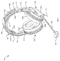
FIG. 1 depicts an oblique view of an example headset, in accordance with an embodiment of the disclosure. Referring toFIG. 1 , there is shown aheadset 100 withheadband 101 andear cups 103. There are also shown amicrophone 107, amicrophone boom arm 109, a line-incable 111,headband slides 113,headband pivots 115,headband endcaps 117, anupper headband 119, and afloating headband 121. Theheadset 100 may be utilized for gaming, phone, or audio playback purposes, for example. In an example scenario, theheadset 100 comprises a powered headset. In another example scenario, theheadset 100 comprises a passive headset. - The
headband pivots 115 couple the headband slides 113 to theheadband endcaps 117, and provide rotational control for theear cups 103. Themicrophone 107 provides electrical signals proportional to sound waves detected and may comprise a directional microphone for picking up audio signals from the user while sensing reduced background noise or sound from other sources, for example. Theboom arm 109 provides a rigid support for themicrophone 107, enabling an optimal position in front of the user for sensing sound from the user. - The
upper headband 119 may be coupled to theheadband endcaps 117, andslider knobs 105 may be incorporated in theupper headband 119 for adjusting the rigidity of theupper headband 119. In an example scenario, in the region where theslider knobs 105 are integrated, the upper headband comprises twostrips 119A of a support structure, e.g., metal or rigid plastic, between which theslider knobs 105 may be actuated. The twoslider knobs 105 shown between thestrips 119A on the right side of theupper headband 119 merely indicate the full range that theslider knobs 105 may travel. Theslider knobs 105 may be coupled to a metal or rigid plastic strip above theslider knobs 105 in theupper headband 119. By sliding theslider knobs 105 downward towards theheadband endcaps 117, the rigid strip may increase the rigidity of theupper headband 119, thereby increasing force of theear cups 103 against the ears of the user. - The
ear cups 103 may be coupled to theheadband 101 viaheadband slides 113 and toheadband endcaps 117 viaheadband pivots 115. The headband slides may comprise metal or rigid plastic and may comprise a fork structure, where the two tines extend into theear cups 103 and may have hemispherical ball features thereon that may be slid into detent features in theear cup 103, thereby providing discrete headset size settings that are held in place utilizing a ball detent structure. This vertical adjustment of theheadband slides 113 may comprise a major adjustment of theheadset 100. The major adjustment changes the size of theheadset 100 as well as the force on the ear. - The force on the ear is adjusted due to the shape and rigidity of the
headband 101 and associated parts, such as theheadband slides 113. Extending the length of the arms of the headset by pulling the headband slides out of theear cups 103 may increase the force on the user's ears, as this decreases the distance between theear cups 103 when not placed on a head, so that more force is needed to expand theheadset 100 over the user's head. In contrast, the force on the ear may be decreased by reducing the length of the arms of the headset by pushing theheadband slides 113 into theear cups 103. - Minor adjustment of the
headset 100 is enabled by thefloating headband 121, which may comprise a flexible band withwire segments 121A that extend from theheadband endcaps 117 into thefloating headband 121 and back down to theheadband endcaps 117. The flexibility in thefloating headband 121 therefore provides a minor adjustment of theheadset 100. - The
ear cups 103 may each comprise anear pad 103A, agimbal gasket 103B, and anouter shell 103C. Theear pads 103A may comprise pads that provide cushion for the user's ears and also provide adequate seal for the ears to exclude ambient noise. Thegimbal gasket 103B may comprise a silicon dust cover, for example, that provides a volume between theear pad 103A andouter shell 103C, to allow theear cup 103 to pivot about a gimbal within theear cup 103. - The
outer shell 103C may comprise an internal gimbal, shown further with respect toFIGS. 4 and5 , for example, that allows theear cups 103 to pivot about the gimbal. This pivoting provides flexibility in the position of theear cups 103 with respect to different shapes and sizes of the head of the user. -
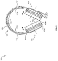
FIG. 2 illustrates a front view of a headset with an internal gimbal, in accordance with an example embodiment of the disclosure. Referring toFIG. 2 , there is shown theheadset 100 with elements as described with respect toFIG. 1 , for example. The arrow in the upper right shows the range of travel for theslider knob 105. - The arrows adjacent to the ear cups 103 illustrate the pivoting of the ear cups 103 with respect to the headband slides 113. While the arrows indicate movement in one direction, the pivoting may be in any direction about the center axis of the ear cups 103 such that the
gimbal gasket 103B may be compressed along any portion of its circumference of the ear cups 103. The pivoting of the ear cups 103 may spread the force on the user's head evenly around the ear, thereby assisting in providing a good seal to exclude ambient noise -
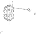
FIG. 3 is a top view of a headset with an internal gimbal, in accordance with an example embodiment of the disclosure. Referring toFIG. 3 , there is shown a side view of theheadset 100 with theheadband 101 andear cups 103. As shown by the arrows, the internal gimbal allows the ear cups 103 to be pivoted in multiple directions about the center axis of each ear cup. -
FIG. 4 illustrates a cut-away view of a headset ear cup with an internal gimbal, in accordance with an example embodiment of the disclosure. Referring toFIG. 4 , there are shown the headband slides 113 and theear cup 103, where theear cup 103 is shown without theouter shell 103C and thegimbal gasket 103B such that the internal structure is visible. Therefore,FIG. 4 shows theear pad 103A, anear cup frame 103D, and aninternal gimbal 106. Theear cup frame 103D comprises a rigid structure that may provide a mechanical support for the connection to the headband via the headband slides 113 and may provide thegimbal post 108 for the internal gimbal. - The
gimbal post 108 may comprise a post in theear cup frame 103D and may be inserted into an aperture in a portion of theear cup 103 on which theear pad 103A is affixed. For example, thegimbal post 108 may comprise a rounded or ball shape in theear cup frame 103D, thereby enabling pivoting of the portion of theear cup 103 on which theear pad 103A is affixed, shown further with respect toFIG. 5 . In another example scenario, thegimbal post 108 may be formed in the portion of theear cup 103 on which theear pad 103A is affixed with an aperture in theear cup frame 103D. -
FIGS. 5 illustrates a side view of the headband ear cup with an internal gimbal, in accordance with an example embodiment of the disclosure. Referring toFIG. 5 , there are shown theear cup 103,internal gimbal 106, andheadband slide 113. As withFIG. 4 , theear cup 103 is shown without theouter shell 103C andgimbal gasket 103B, so as to show the internal gimbal structure. Accordingly,FIG. 5 shows theear cup frame 103D, thepad frame 103E, and thespeaker driver 110, none of which would be visible if theouter shell 103C andgimbal gasket 103B were shown. Theinternal gimbal 106 may comprise agimbal post 108 and anaperture 112 where theaperture 112 is formed in the pad frame 108E. - The
speaker driver 110 comprises a magnetic coil, for example, and associated electronic components for converting an electrical signal to a sound signal. Thepad frame 103E comprises a supporting frame for theear cup 103 that connects to thegimbal post 108 and at least partially encompasses thespeaker driver 110. Thepad frame 103E extends to the outer edge of theear cup 103 and comprises support structure upon which theear pad 103A may be affixed. - In an example scenario, the
gimbal post 108 may comprise a center post that is within theopening 112 in thepad frame 103E. The pivot point may be wider at the tip within thepad frame 103E so as to lock thepad frame 103A to theear cup frame 103D, for example. Thegimbal post 108 in theopening 112 may enable full pivoting action for theear pad 103A with respect to theear cup frame 103D where the distance between theear pad 103A and theear cup frame 103D, shown by the dashed lines inFIG. 5 , may vary depending on the positioning of the headset on the user's head. - The
gimbal post 108 andopening 112 provide a pivoting motion for the ear cups 103 such that a force on the head of the headset user may be spread evenly around their ears and provide a comfortable and proper seal for exclusion of ambient noise. The pivoting may be about an axis defined by thegimbal post 108. -
FIG. 6 is a flowchart illustrating an example process for a headset with an internal gimbal. Referring toFIG. 6 , there is shown aflow chart 600, comprising a plurality of example steps. Instep 602, theheadset 100 may be powered up for gaming, phone, or music playback purposes where the headset is a powered headset, or may be plugged into a signal source if the headset is a passive headset. Instep 604, the headset may be placed on a user's head and instep 606, the position of the ear cups may pivot about the internal gimbal to provide desired fit to the user's head. - In an example embodiment of the disclosure a headset with internal gimbal is disclosed where the headset may comprise a headband, a headband, and ear cups coupled to the headband, where each ear cup may be coupled to the headband utilizing an internal gimbal, which may comprise a gimbal post in an aperture. The gimbal post may comprise a tip that is wider than its base. The tip may be rounded.
- The headband may comprise headband endcaps at each end of the headband. A headband slide may be coupled to each headband endcap. The headband ear cups may be coupled to the headband via the headband slides. Each headband slide may be coupled to a headband endcap via a headband pivot. The headband pivot may provide rotational motion of the ear cups with respect to the headband. The force on ears of a user of the headset may be spread evenly by the internal gimbals.
- While the present method and/or system has been described with reference to certain implementations, it will be understood by those skilled in the art that various changes may be made and equivalents may be substituted without departing from the scope of the present method and/or system. In addition, many modifications may be made to adapt a particular situation or material to the teachings of the present disclosure without departing from its scope. Therefore, it is intended that the present method and/or system not be limited to the particular implementations disclosed, but that the present method and/or system will include all implementations falling within the scope of the appended claims.
Claims (20)
- An audio headset, the headset comprising:a headband; andear cups coupled to the headband, wherein each ear cup is coupled to the headband utilizing an internal gimbal.
- The system of claim 1, wherein the internal gimbal comprises a gimbal post in an aperture.
- The system of claim 1, wherein the gimbal post comprises a tip that is wider than its base.
- The system of claim 3, wherein the tip is rounded.
- The system of claim 1, wherein the headband comprises headband endcaps at each end of the headband.
- The system of claim 5, wherein a headband slide is coupled to each headband endcap.
- The system of claim 6, wherein the headband ear cups are coupled to the headband via the headband slides.
- The system of claim 6, wherein each headband slide is coupled to a headband endcap via a headband pivot.
- The system of claim 8, wherein the headband pivot provides rotational motion of the ear cups with respect to the headband.
- The system of claim 1, wherein the force on ears of a user of the headset is spread evenly by the internal gimbals.
- A method for adjusting a headset, the method comprising:in a headset comprising:a headband; andear cups coupled to the headband, wherein each ear cup is coupled to the headband utilizing an internal gimbal;spreading a force of the ear cups around ears of a user's head utilizing the internal gimbals.
- The method of claim 11, wherein the internal gimbal comprises a gimbal post in an aperture.
- The method of claim 11, wherein the gimbal post comprises a tip that is wider than its base.
- The method of claim 13, wherein the tip is rounded.
- The method of claim 11, wherein the headband comprises headband endcaps at each end of the headband.
- The method of claim 15, wherein a headband slide is coupled to each headband endcap.
- The method of claim 16, wherein the headband ear cups are coupled to the headband via the headband slides.
- The method of claim 16, wherein each headband slide is coupled to a headband endcap via a headband pivot.
- The method of claim 18, wherein the headband pivot provides rotational motion of the ear cups with respect to the headband.
- An audio headset, the headset comprising:a headband; andear cups coupled to the headband, wherein each ear cup is coupled to the headband utilizing an internal gimbal that, when the audio headset is worn by a user, spreads a force of the ear cups around the user's head.
Applications Claiming Priority (1)
| Application Number | Priority Date | Filing Date | Title |
|---|---|---|---|
| US14/801,655 US10667029B2 (en) | 2015-07-16 | 2015-07-16 | Headset with internal gimbal |
Publications (2)
| Publication Number | Publication Date |
|---|---|
| EP3119108A1 true EP3119108A1 (en) | 2017-01-18 |
| EP3119108B1 EP3119108B1 (en) | 2020-03-11 |
Family
ID=56418434
Family Applications (1)
| Application Number | Title | Priority Date | Filing Date |
|---|---|---|---|
| EP16179833.5A Active EP3119108B1 (en) | 2015-07-16 | 2016-07-16 | A headset with internal gimbal |
Country Status (3)
| Country | Link |
|---|---|
| US (4) | US10667029B2 (en) |
| EP (1) | EP3119108B1 (en) |
| ES (1) | ES2786571T3 (en) |
Cited By (1)
| Publication number | Priority date | Publication date | Assignee | Title |
|---|---|---|---|---|
| CN110521216A (en) * | 2017-04-14 | 2019-11-29 | 伯斯有限公司 | Stable headband |
Families Citing this family (16)
| Publication number | Priority date | Publication date | Assignee | Title |
|---|---|---|---|---|
| US10667029B2 (en) | 2015-07-16 | 2020-05-26 | Voyetra Turtle Beach, Inc. | Headset with internal gimbal |
| US10129632B2 (en) * | 2017-02-01 | 2018-11-13 | Bose Corporation | Headphone |
| US10085085B2 (en) * | 2017-02-01 | 2018-09-25 | Bose Corporation | Headphone |
| TWI781990B (en) * | 2018-03-15 | 2022-11-01 | 圓剛科技股份有限公司 | Headphone |
| USD940099S1 (en) * | 2019-11-21 | 2022-01-04 | Mingxun Zheng | Audio headset |
| USD935439S1 (en) * | 2019-11-26 | 2021-11-09 | Mingxun Zheng | Audio headset |
| USD941798S1 (en) * | 2020-01-21 | 2022-01-25 | 3M Innovative Properties Company | Headset |
| USD890131S1 (en) * | 2020-04-07 | 2020-07-14 | Guifeng Shen | Headphone |
| USD914637S1 (en) * | 2020-05-11 | 2021-03-30 | Guifeng Shen | Headphone |
| JP1699063S (en) * | 2020-08-01 | 2021-11-08 | ||
| US11595747B2 (en) * | 2021-04-30 | 2023-02-28 | Logitech Europe S.A. | Headset with membrane coupling connecting the headband to the earpieces |
| USD1007464S1 (en) * | 2021-07-06 | 2023-12-12 | Mingxun Zheng | Audio headset |
| USD1003856S1 (en) * | 2021-09-10 | 2023-11-07 | Shenzhen Wonderhuge Electronics Co., Ltd | Headphone |
| USD997125S1 (en) * | 2021-09-28 | 2023-08-29 | David Clark Company Incorporated | Headset |
| USD1010611S1 (en) * | 2021-12-09 | 2024-01-09 | David Clark Company Incorporated | Headset |
| JP1727940S (en) * | 2021-12-28 | 2022-10-21 | headphone |
Citations (6)
| Publication number | Priority date | Publication date | Assignee | Title |
|---|---|---|---|---|
| AT322651B (en) * | 1973-05-18 | 1975-06-10 | Akg Akustische Kino Geraete | ARRANGEMENT FOR HEADPHONES |
| DE2540839A1 (en) * | 1974-09-12 | 1976-04-01 | Nippon Musical Instruments Mfg | Headphones with ball and socket joints - has joints between headband and ear pieces to allow earpieces to rotate as well as tilt |
| US5469505A (en) * | 1992-07-08 | 1995-11-21 | Acs Wireless, Inc. | Communications headset having a ball joint-mounted receiver assembly |
| EP1622419A1 (en) * | 2004-07-28 | 2006-02-01 | AKG Acoustics GmbH | Headphone |
| US20110206216A1 (en) * | 2010-01-04 | 2011-08-25 | Beats Electronics, Llc | Headphone |
| WO2012094176A2 (en) * | 2011-01-03 | 2012-07-12 | Beats Electronics, Llc | Audio listening system |
Family Cites Families (41)
| Publication number | Priority date | Publication date | Assignee | Title |
|---|---|---|---|---|
| US3505684A (en) * | 1969-03-03 | 1970-04-14 | American Optical Corp | Attachment mounting means for hearing protector ear cups |
| US3719954A (en) * | 1970-02-12 | 1973-03-13 | American Optical Corp | Head set construction |
| US4027113A (en) * | 1974-09-12 | 1977-05-31 | Nippon Gakki Seizo Kabushiki Kaisha | Headphone |
| US3918098A (en) * | 1975-01-22 | 1975-11-11 | Sierra Eng Co | Threaded earcup suspension system |
| SE412517B (en) * | 1976-09-30 | 1980-03-10 | Gullfiber Ab | HORSE PROTECTION WITH TWO HORSE PROTECTORS, MOUNTED BY A COUPLE |
| US4065645B1 (en) * | 1976-10-26 | 1993-05-18 | Audiotronics Corporation | Headset |
| US4471496A (en) * | 1983-06-27 | 1984-09-18 | Cabot Corporation | Articulated earmuff-to-headband attachment construction |
| US5109424A (en) * | 1989-01-19 | 1992-04-28 | Koss Corporation | Stereo headphones with plug, receptacle and securing plates |
| US5117465A (en) * | 1991-03-15 | 1992-05-26 | Unex Corporation | Earphone with adjustable headband with progressively shallow detents |
| US5369857A (en) * | 1992-12-08 | 1994-12-06 | Hello Direct | Method of making a telephone headset |
| JP4062824B2 (en) * | 1999-07-13 | 2008-03-19 | ソニー株式会社 | Headphone |
| SE0000465D0 (en) * | 2000-02-15 | 2000-02-15 | Kompositprodukter Ab | Ear protection |
| US6611963B2 (en) * | 2001-10-26 | 2003-09-02 | Bacon Usa Safety, Inc. | Wire band earmuff |
| US6724906B2 (en) * | 2002-05-07 | 2004-04-20 | Alex Naksen | Adjustable headphone |
| AT413923B (en) * | 2003-01-31 | 2006-07-15 | Akg Acoustics Gmbh | HEADPHONE |
| US7171698B2 (en) * | 2003-02-07 | 2007-02-06 | Jackson Products, Inc. | Earmuff having anatomically correct ear cups |
| US20080170738A1 (en) * | 2007-01-16 | 2008-07-17 | Sony Ericsson Mobile Communications Ab | Adjustable earphones for portable devices |
| US8503710B1 (en) * | 2007-06-01 | 2013-08-06 | Plantronics, Inc. | Headset with rotatable earpiece |
| US8443467B2 (en) * | 2008-02-15 | 2013-05-21 | Sound Team Enterprise Co., Ltd. | Earmuff assembly |
| AU2009201813B2 (en) * | 2008-05-14 | 2013-08-29 | Nixon, Inc. | Headphones |
| NZ591642A (en) * | 2008-08-25 | 2013-10-25 | Loud & Clear Safety Pty Ltd | Safety apparatus |
| US8290194B2 (en) * | 2009-07-29 | 2012-10-16 | Encounters Products Corp. | Wireless headphone integrated with an adjustment control device |
| TWM370905U (en) * | 2009-08-25 | 2009-12-11 | Gamma Inc | Headphone and the rotating axle |
| US20120140973A1 (en) * | 2010-12-02 | 2012-06-07 | Robert Olodort | Collapsible headphone |
| US20120269374A1 (en) * | 2011-01-05 | 2012-10-25 | Noel Lee | Automatically adjusting headphones |
| EP2523469B1 (en) * | 2011-05-11 | 2014-06-18 | Sennheiser Communications A/S | Headphone with a headband |
| DE102011076179A1 (en) * | 2011-05-20 | 2012-11-22 | Sennheiser Electronic Gmbh & Co. Kg | Earphone with headset has attenuation unit that is designed as separate component for damping noise generated through electrical connecting cable |
| US9288568B2 (en) * | 2011-09-02 | 2016-03-15 | Advanced Audio Llc | Headphone system for earbud speakers |
| US8861770B2 (en) * | 2013-01-23 | 2014-10-14 | Koss Corporation | Headband for personal speakers |
| US9749728B2 (en) * | 2013-06-07 | 2017-08-29 | Microsoft Technology Licensing, Llc | Audio headset accommodating ear geometry variations |
| WO2014207979A1 (en) * | 2013-06-28 | 2014-12-31 | ソニー株式会社 | Headphone |
| US9681212B2 (en) * | 2013-11-01 | 2017-06-13 | Global Drumz, Inc. | Headphones with multiple equalization presets for different genres of music |
| US8942385B1 (en) * | 2013-11-01 | 2015-01-27 | Global Drumz, Inc. | Headphones with multiple equalization presets for different genres of music |
| DK2892246T3 (en) * | 2014-01-07 | 2020-01-02 | Sennheiser Communications As | Headphones with passage over the head |
| WO2015108854A1 (en) * | 2014-01-14 | 2015-07-23 | Artisent, Llc | Pivot-arm assembly for a helmet mounted headset |
| US9838776B2 (en) * | 2014-07-02 | 2017-12-05 | Sonetics Holdings, Inc. | Restricted ball and socket joint for headset earcup |
| US9736571B2 (en) * | 2014-11-10 | 2017-08-15 | The Quest Group | Headphone suspension system |
| US9522086B2 (en) * | 2015-01-06 | 2016-12-20 | Honeywell International Inc. | Headband folding mechanism allowing two axis folding directions |
| US10667029B2 (en) | 2015-07-16 | 2020-05-26 | Voyetra Turtle Beach, Inc. | Headset with internal gimbal |
| US10764672B2 (en) * | 2017-12-29 | 2020-09-01 | Mrspeakers, Llc | Over-ear headphone with hinge-free headband |
| US11546686B2 (en) * | 2021-04-06 | 2023-01-03 | Dan Clark Audio, Inc. | Headphone ear pad system |
-
2015
- 2015-07-16 US US14/801,655 patent/US10667029B2/en active Active
-
2016
- 2016-07-16 ES ES16179833T patent/ES2786571T3/en active Active
- 2016-07-16 EP EP16179833.5A patent/EP3119108B1/en active Active
-
2020
- 2020-05-13 US US15/931,287 patent/US11218790B2/en active Active
-
2021
- 2021-12-01 US US17/539,666 patent/US11683627B2/en active Active
-
2023
- 2023-05-03 US US18/311,345 patent/US20230276158A1/en active Pending
Patent Citations (6)
| Publication number | Priority date | Publication date | Assignee | Title |
|---|---|---|---|---|
| AT322651B (en) * | 1973-05-18 | 1975-06-10 | Akg Akustische Kino Geraete | ARRANGEMENT FOR HEADPHONES |
| DE2540839A1 (en) * | 1974-09-12 | 1976-04-01 | Nippon Musical Instruments Mfg | Headphones with ball and socket joints - has joints between headband and ear pieces to allow earpieces to rotate as well as tilt |
| US5469505A (en) * | 1992-07-08 | 1995-11-21 | Acs Wireless, Inc. | Communications headset having a ball joint-mounted receiver assembly |
| EP1622419A1 (en) * | 2004-07-28 | 2006-02-01 | AKG Acoustics GmbH | Headphone |
| US20110206216A1 (en) * | 2010-01-04 | 2011-08-25 | Beats Electronics, Llc | Headphone |
| WO2012094176A2 (en) * | 2011-01-03 | 2012-07-12 | Beats Electronics, Llc | Audio listening system |
Cited By (1)
| Publication number | Priority date | Publication date | Assignee | Title |
|---|---|---|---|---|
| CN110521216A (en) * | 2017-04-14 | 2019-11-29 | 伯斯有限公司 | Stable headband |
Also Published As
| Publication number | Publication date |
|---|---|
| US10667029B2 (en) | 2020-05-26 |
| ES2786571T3 (en) | 2020-10-13 |
| EP3119108B1 (en) | 2020-03-11 |
| US11683627B2 (en) | 2023-06-20 |
| US20230276158A1 (en) | 2023-08-31 |
| US11218790B2 (en) | 2022-01-04 |
| US20220095031A1 (en) | 2022-03-24 |
| US20170019724A1 (en) | 2017-01-19 |
| US20200275180A1 (en) | 2020-08-27 |
Similar Documents
| Publication | Publication Date | Title |
|---|---|---|
| US11218790B2 (en) | Headset with internal gimbal | |
| US11240589B2 (en) | Headset with force isolation | |
| US11350206B2 (en) | Headset with major and minor adjustments | |
| CN105208475A (en) | Earphone | |
| EP2822292B1 (en) | A car speakerphone with automatic adjustment of microphone directivity | |
| US20200092626A1 (en) | A wearable device | |
| KR101737686B1 (en) | Support device for microphone of earphone | |
| CN108600931A (en) | A kind of speaker diaphragm and its manufacturing method and earphone using the diaphragm | |
| CN208940173U (en) | A kind of foldable earphone support arm structure | |
| US10779597B2 (en) | Brim clip with communication device |
Legal Events
| Date | Code | Title | Description |
|---|---|---|---|
| PUAI | Public reference made under article 153(3) epc to a published international application that has entered the european phase |
Free format text: ORIGINAL CODE: 0009012 |
|
| STAA | Information on the status of an ep patent application or granted ep patent |
Free format text: STATUS: THE APPLICATION HAS BEEN PUBLISHED |
|
| AK | Designated contracting states |
Kind code of ref document: A1 Designated state(s): AL AT BE BG CH CY CZ DE DK EE ES FI FR GB GR HR HU IE IS IT LI LT LU LV MC MK MT NL NO PL PT RO RS SE SI SK SM TR |
|
| AX | Request for extension of the european patent |
Extension state: BA ME |
|
| STAA | Information on the status of an ep patent application or granted ep patent |
Free format text: STATUS: REQUEST FOR EXAMINATION WAS MADE |
|
| 17P | Request for examination filed |
Effective date: 20170717 |
|
| RBV | Designated contracting states (corrected) |
Designated state(s): AL AT BE BG CH CY CZ DE DK EE ES FI FR GB GR HR HU IE IS IT LI LT LU LV MC MK MT NL NO PL PT RO RS SE SI SK SM TR |
|
| STAA | Information on the status of an ep patent application or granted ep patent |
Free format text: STATUS: EXAMINATION IS IN PROGRESS |
|
| 17Q | First examination report despatched |
Effective date: 20180309 |
|
| GRAP | Despatch of communication of intention to grant a patent |
Free format text: ORIGINAL CODE: EPIDOSNIGR1 |
|
| STAA | Information on the status of an ep patent application or granted ep patent |
Free format text: STATUS: GRANT OF PATENT IS INTENDED |
|
| RIC1 | Information provided on ipc code assigned before grant |
Ipc: H04R 5/033 20060101ALN20190814BHEP Ipc: H04R 1/10 20060101AFI20190814BHEP |
|
| INTG | Intention to grant announced |
Effective date: 20190830 |
|
| GRAS | Grant fee paid |
Free format text: ORIGINAL CODE: EPIDOSNIGR3 |
|
| GRAA | (expected) grant |
Free format text: ORIGINAL CODE: 0009210 |
|
| STAA | Information on the status of an ep patent application or granted ep patent |
Free format text: STATUS: THE PATENT HAS BEEN GRANTED |
|
| AK | Designated contracting states |
Kind code of ref document: B1 Designated state(s): AL AT BE BG CH CY CZ DE DK EE ES FI FR GB GR HR HU IE IS IT LI LT LU LV MC MK MT NL NO PL PT RO RS SE SI SK SM TR |
|
| REG | Reference to a national code |
Ref country code: GB Ref legal event code: FG4D |
|
| REG | Reference to a national code |
Ref country code: CH Ref legal event code: EP |
|
| REG | Reference to a national code |
Ref country code: AT Ref legal event code: REF Ref document number: 1244655 Country of ref document: AT Kind code of ref document: T Effective date: 20200315 |
|
| REG | Reference to a national code |
Ref country code: IE Ref legal event code: FG4D |
|
| REG | Reference to a national code |
Ref country code: DE Ref legal event code: R096 Ref document number: 602016031379 Country of ref document: DE |
|
| PG25 | Lapsed in a contracting state [announced via postgrant information from national office to epo] |
Ref country code: NO Free format text: LAPSE BECAUSE OF FAILURE TO SUBMIT A TRANSLATION OF THE DESCRIPTION OR TO PAY THE FEE WITHIN THE PRESCRIBED TIME-LIMIT Effective date: 20200611 Ref country code: FI Free format text: LAPSE BECAUSE OF FAILURE TO SUBMIT A TRANSLATION OF THE DESCRIPTION OR TO PAY THE FEE WITHIN THE PRESCRIBED TIME-LIMIT Effective date: 20200311 Ref country code: RS Free format text: LAPSE BECAUSE OF FAILURE TO SUBMIT A TRANSLATION OF THE DESCRIPTION OR TO PAY THE FEE WITHIN THE PRESCRIBED TIME-LIMIT Effective date: 20200311 |
|
| REG | Reference to a national code |
Ref country code: NL Ref legal event code: MP Effective date: 20200311 |
|
| PG25 | Lapsed in a contracting state [announced via postgrant information from national office to epo] |
Ref country code: BG Free format text: LAPSE BECAUSE OF FAILURE TO SUBMIT A TRANSLATION OF THE DESCRIPTION OR TO PAY THE FEE WITHIN THE PRESCRIBED TIME-LIMIT Effective date: 20200611 Ref country code: LV Free format text: LAPSE BECAUSE OF FAILURE TO SUBMIT A TRANSLATION OF THE DESCRIPTION OR TO PAY THE FEE WITHIN THE PRESCRIBED TIME-LIMIT Effective date: 20200311 Ref country code: SE Free format text: LAPSE BECAUSE OF FAILURE TO SUBMIT A TRANSLATION OF THE DESCRIPTION OR TO PAY THE FEE WITHIN THE PRESCRIBED TIME-LIMIT Effective date: 20200311 Ref country code: HR Free format text: LAPSE BECAUSE OF FAILURE TO SUBMIT A TRANSLATION OF THE DESCRIPTION OR TO PAY THE FEE WITHIN THE PRESCRIBED TIME-LIMIT Effective date: 20200311 Ref country code: GR Free format text: LAPSE BECAUSE OF FAILURE TO SUBMIT A TRANSLATION OF THE DESCRIPTION OR TO PAY THE FEE WITHIN THE PRESCRIBED TIME-LIMIT Effective date: 20200612 |
|
| REG | Reference to a national code |
Ref country code: LT Ref legal event code: MG4D |
|
| PG25 | Lapsed in a contracting state [announced via postgrant information from national office to epo] |
Ref country code: NL Free format text: LAPSE BECAUSE OF FAILURE TO SUBMIT A TRANSLATION OF THE DESCRIPTION OR TO PAY THE FEE WITHIN THE PRESCRIBED TIME-LIMIT Effective date: 20200311 |
|
| REG | Reference to a national code |
Ref country code: ES Ref legal event code: FG2A Ref document number: 2786571 Country of ref document: ES Kind code of ref document: T3 Effective date: 20201013 |
|
| PG25 | Lapsed in a contracting state [announced via postgrant information from national office to epo] |
Ref country code: PT Free format text: LAPSE BECAUSE OF FAILURE TO SUBMIT A TRANSLATION OF THE DESCRIPTION OR TO PAY THE FEE WITHIN THE PRESCRIBED TIME-LIMIT Effective date: 20200805 Ref country code: CZ Free format text: LAPSE BECAUSE OF FAILURE TO SUBMIT A TRANSLATION OF THE DESCRIPTION OR TO PAY THE FEE WITHIN THE PRESCRIBED TIME-LIMIT Effective date: 20200311 Ref country code: RO Free format text: LAPSE BECAUSE OF FAILURE TO SUBMIT A TRANSLATION OF THE DESCRIPTION OR TO PAY THE FEE WITHIN THE PRESCRIBED TIME-LIMIT Effective date: 20200311 Ref country code: IS Free format text: LAPSE BECAUSE OF FAILURE TO SUBMIT A TRANSLATION OF THE DESCRIPTION OR TO PAY THE FEE WITHIN THE PRESCRIBED TIME-LIMIT Effective date: 20200711 Ref country code: SK Free format text: LAPSE BECAUSE OF FAILURE TO SUBMIT A TRANSLATION OF THE DESCRIPTION OR TO PAY THE FEE WITHIN THE PRESCRIBED TIME-LIMIT Effective date: 20200311 Ref country code: LT Free format text: LAPSE BECAUSE OF FAILURE TO SUBMIT A TRANSLATION OF THE DESCRIPTION OR TO PAY THE FEE WITHIN THE PRESCRIBED TIME-LIMIT Effective date: 20200311 Ref country code: EE Free format text: LAPSE BECAUSE OF FAILURE TO SUBMIT A TRANSLATION OF THE DESCRIPTION OR TO PAY THE FEE WITHIN THE PRESCRIBED TIME-LIMIT Effective date: 20200311 Ref country code: SM Free format text: LAPSE BECAUSE OF FAILURE TO SUBMIT A TRANSLATION OF THE DESCRIPTION OR TO PAY THE FEE WITHIN THE PRESCRIBED TIME-LIMIT Effective date: 20200311 |
|
| REG | Reference to a national code |
Ref country code: AT Ref legal event code: MK05 Ref document number: 1244655 Country of ref document: AT Kind code of ref document: T Effective date: 20200311 |
|
| REG | Reference to a national code |
Ref country code: DE Ref legal event code: R097 Ref document number: 602016031379 Country of ref document: DE |
|
| PLBE | No opposition filed within time limit |
Free format text: ORIGINAL CODE: 0009261 |
|
| STAA | Information on the status of an ep patent application or granted ep patent |
Free format text: STATUS: NO OPPOSITION FILED WITHIN TIME LIMIT |
|
| PG25 | Lapsed in a contracting state [announced via postgrant information from national office to epo] |
Ref country code: DK Free format text: LAPSE BECAUSE OF FAILURE TO SUBMIT A TRANSLATION OF THE DESCRIPTION OR TO PAY THE FEE WITHIN THE PRESCRIBED TIME-LIMIT Effective date: 20200311 Ref country code: AT Free format text: LAPSE BECAUSE OF FAILURE TO SUBMIT A TRANSLATION OF THE DESCRIPTION OR TO PAY THE FEE WITHIN THE PRESCRIBED TIME-LIMIT Effective date: 20200311 |
|
| 26N | No opposition filed |
Effective date: 20201214 |
|
| PG25 | Lapsed in a contracting state [announced via postgrant information from national office to epo] |
Ref country code: PL Free format text: LAPSE BECAUSE OF FAILURE TO SUBMIT A TRANSLATION OF THE DESCRIPTION OR TO PAY THE FEE WITHIN THE PRESCRIBED TIME-LIMIT Effective date: 20200311 Ref country code: SI Free format text: LAPSE BECAUSE OF FAILURE TO SUBMIT A TRANSLATION OF THE DESCRIPTION OR TO PAY THE FEE WITHIN THE PRESCRIBED TIME-LIMIT Effective date: 20200311 Ref country code: MC Free format text: LAPSE BECAUSE OF FAILURE TO SUBMIT A TRANSLATION OF THE DESCRIPTION OR TO PAY THE FEE WITHIN THE PRESCRIBED TIME-LIMIT Effective date: 20200311 |
|
| REG | Reference to a national code |
Ref country code: CH Ref legal event code: PL |
|
| REG | Reference to a national code |
Ref country code: BE Ref legal event code: MM Effective date: 20200731 |
|
| PG25 | Lapsed in a contracting state [announced via postgrant information from national office to epo] |
Ref country code: CH Free format text: LAPSE BECAUSE OF NON-PAYMENT OF DUE FEES Effective date: 20200731 Ref country code: LU Free format text: LAPSE BECAUSE OF NON-PAYMENT OF DUE FEES Effective date: 20200716 Ref country code: LI Free format text: LAPSE BECAUSE OF NON-PAYMENT OF DUE FEES Effective date: 20200731 |
|
| PG25 | Lapsed in a contracting state [announced via postgrant information from national office to epo] |
Ref country code: BE Free format text: LAPSE BECAUSE OF NON-PAYMENT OF DUE FEES Effective date: 20200731 |
|
| PG25 | Lapsed in a contracting state [announced via postgrant information from national office to epo] |
Ref country code: IE Free format text: LAPSE BECAUSE OF NON-PAYMENT OF DUE FEES Effective date: 20200716 |
|
| PG25 | Lapsed in a contracting state [announced via postgrant information from national office to epo] |
Ref country code: TR Free format text: LAPSE BECAUSE OF FAILURE TO SUBMIT A TRANSLATION OF THE DESCRIPTION OR TO PAY THE FEE WITHIN THE PRESCRIBED TIME-LIMIT Effective date: 20200311 Ref country code: MT Free format text: LAPSE BECAUSE OF FAILURE TO SUBMIT A TRANSLATION OF THE DESCRIPTION OR TO PAY THE FEE WITHIN THE PRESCRIBED TIME-LIMIT Effective date: 20200311 Ref country code: CY Free format text: LAPSE BECAUSE OF FAILURE TO SUBMIT A TRANSLATION OF THE DESCRIPTION OR TO PAY THE FEE WITHIN THE PRESCRIBED TIME-LIMIT Effective date: 20200311 |
|
| PG25 | Lapsed in a contracting state [announced via postgrant information from national office to epo] |
Ref country code: MK Free format text: LAPSE BECAUSE OF FAILURE TO SUBMIT A TRANSLATION OF THE DESCRIPTION OR TO PAY THE FEE WITHIN THE PRESCRIBED TIME-LIMIT Effective date: 20200311 Ref country code: AL Free format text: LAPSE BECAUSE OF FAILURE TO SUBMIT A TRANSLATION OF THE DESCRIPTION OR TO PAY THE FEE WITHIN THE PRESCRIBED TIME-LIMIT Effective date: 20200311 |
|
| P01 | Opt-out of the competence of the unified patent court (upc) registered |
Effective date: 20230516 |
|
| P02 | Opt-out of the competence of the unified patent court (upc) changed |
Effective date: 20230807 |
|
| PGFP | Annual fee paid to national office [announced via postgrant information from national office to epo] |
Ref country code: IT Payment date: 20230727 Year of fee payment: 8 Ref country code: GB Payment date: 20230719 Year of fee payment: 8 Ref country code: ES Payment date: 20230821 Year of fee payment: 8 |
|
| PGFP | Annual fee paid to national office [announced via postgrant information from national office to epo] |
Ref country code: FR Payment date: 20230724 Year of fee payment: 8 Ref country code: DE Payment date: 20230809 Year of fee payment: 8 |