EP3124306A1 - An inlet check valve for a filler pipe welded to a liquid tank - Google Patents
An inlet check valve for a filler pipe welded to a liquid tank Download PDFInfo
- Publication number
- EP3124306A1 EP3124306A1 EP15306253.4A EP15306253A EP3124306A1 EP 3124306 A1 EP3124306 A1 EP 3124306A1 EP 15306253 A EP15306253 A EP 15306253A EP 3124306 A1 EP3124306 A1 EP 3124306A1
- Authority
- EP
- European Patent Office
- Prior art keywords
- filler pipe
- check valve
- inlet check
- tank
- internal wall
- Prior art date
- Legal status (The legal status is an assumption and is not a legal conclusion. Google has not performed a legal analysis and makes no representation as to the accuracy of the status listed.)
- Withdrawn
Links
Images


Classifications
-
- B—PERFORMING OPERATIONS; TRANSPORTING
- B60—VEHICLES IN GENERAL
- B60K—ARRANGEMENT OR MOUNTING OF PROPULSION UNITS OR OF TRANSMISSIONS IN VEHICLES; ARRANGEMENT OR MOUNTING OF PLURAL DIVERSE PRIME-MOVERS IN VEHICLES; AUXILIARY DRIVES FOR VEHICLES; INSTRUMENTATION OR DASHBOARDS FOR VEHICLES; ARRANGEMENTS IN CONNECTION WITH COOLING, AIR INTAKE, GAS EXHAUST OR FUEL SUPPLY OF PROPULSION UNITS IN VEHICLES
- B60K15/00—Arrangement in connection with fuel supply of combustion engines or other fuel consuming energy converters, e.g. fuel cells; Mounting or construction of fuel tanks
- B60K15/03—Fuel tanks
- B60K15/04—Tank inlets
-
- F—MECHANICAL ENGINEERING; LIGHTING; HEATING; WEAPONS; BLASTING
- F16—ENGINEERING ELEMENTS AND UNITS; GENERAL MEASURES FOR PRODUCING AND MAINTAINING EFFECTIVE FUNCTIONING OF MACHINES OR INSTALLATIONS; THERMAL INSULATION IN GENERAL
- F16K—VALVES; TAPS; COCKS; ACTUATING-FLOATS; DEVICES FOR VENTING OR AERATING
- F16K27/00—Construction of housing; Use of materials therefor
- F16K27/02—Construction of housing; Use of materials therefor of lift valves
- F16K27/0209—Check valves or pivoted valves
- F16K27/0227—Check valves or pivoted valves with the valve members swinging around an axis located at the edge of or outside the valve member
-
- B—PERFORMING OPERATIONS; TRANSPORTING
- B60—VEHICLES IN GENERAL
- B60K—ARRANGEMENT OR MOUNTING OF PROPULSION UNITS OR OF TRANSMISSIONS IN VEHICLES; ARRANGEMENT OR MOUNTING OF PLURAL DIVERSE PRIME-MOVERS IN VEHICLES; AUXILIARY DRIVES FOR VEHICLES; INSTRUMENTATION OR DASHBOARDS FOR VEHICLES; ARRANGEMENTS IN CONNECTION WITH COOLING, AIR INTAKE, GAS EXHAUST OR FUEL SUPPLY OF PROPULSION UNITS IN VEHICLES
- B60K15/00—Arrangement in connection with fuel supply of combustion engines or other fuel consuming energy converters, e.g. fuel cells; Mounting or construction of fuel tanks
- B60K15/03—Fuel tanks
- B60K2015/03328—Arrangements or special measures related to fuel tanks or fuel handling
- B60K2015/03453—Arrangements or special measures related to fuel tanks or fuel handling for fixing or mounting parts of the fuel tank together
- B60K2015/0346—Arrangements or special measures related to fuel tanks or fuel handling for fixing or mounting parts of the fuel tank together by welding
-
- B—PERFORMING OPERATIONS; TRANSPORTING
- B60—VEHICLES IN GENERAL
- B60K—ARRANGEMENT OR MOUNTING OF PROPULSION UNITS OR OF TRANSMISSIONS IN VEHICLES; ARRANGEMENT OR MOUNTING OF PLURAL DIVERSE PRIME-MOVERS IN VEHICLES; AUXILIARY DRIVES FOR VEHICLES; INSTRUMENTATION OR DASHBOARDS FOR VEHICLES; ARRANGEMENTS IN CONNECTION WITH COOLING, AIR INTAKE, GAS EXHAUST OR FUEL SUPPLY OF PROPULSION UNITS IN VEHICLES
- B60K15/00—Arrangement in connection with fuel supply of combustion engines or other fuel consuming energy converters, e.g. fuel cells; Mounting or construction of fuel tanks
- B60K15/03—Fuel tanks
- B60K15/04—Tank inlets
- B60K2015/0458—Details of the tank inlet
- B60K2015/0461—Details of the tank inlet comprising a filler pipe shutter, e.g. trap, door or flap for fuel inlet
-
- B—PERFORMING OPERATIONS; TRANSPORTING
- B60—VEHICLES IN GENERAL
- B60K—ARRANGEMENT OR MOUNTING OF PROPULSION UNITS OR OF TRANSMISSIONS IN VEHICLES; ARRANGEMENT OR MOUNTING OF PLURAL DIVERSE PRIME-MOVERS IN VEHICLES; AUXILIARY DRIVES FOR VEHICLES; INSTRUMENTATION OR DASHBOARDS FOR VEHICLES; ARRANGEMENTS IN CONNECTION WITH COOLING, AIR INTAKE, GAS EXHAUST OR FUEL SUPPLY OF PROPULSION UNITS IN VEHICLES
- B60K15/00—Arrangement in connection with fuel supply of combustion engines or other fuel consuming energy converters, e.g. fuel cells; Mounting or construction of fuel tanks
- B60K15/03—Fuel tanks
- B60K15/04—Tank inlets
- B60K2015/0458—Details of the tank inlet
- B60K2015/047—Manufacturing of the fuel inlet or connecting elements to fuel inlet, e.g. pipes or venting tubes
-
- B—PERFORMING OPERATIONS; TRANSPORTING
- B60—VEHICLES IN GENERAL
- B60K—ARRANGEMENT OR MOUNTING OF PROPULSION UNITS OR OF TRANSMISSIONS IN VEHICLES; ARRANGEMENT OR MOUNTING OF PLURAL DIVERSE PRIME-MOVERS IN VEHICLES; AUXILIARY DRIVES FOR VEHICLES; INSTRUMENTATION OR DASHBOARDS FOR VEHICLES; ARRANGEMENTS IN CONNECTION WITH COOLING, AIR INTAKE, GAS EXHAUST OR FUEL SUPPLY OF PROPULSION UNITS IN VEHICLES
- B60K15/00—Arrangement in connection with fuel supply of combustion engines or other fuel consuming energy converters, e.g. fuel cells; Mounting or construction of fuel tanks
- B60K15/03—Fuel tanks
- B60K15/04—Tank inlets
- B60K2015/0458—Details of the tank inlet
- B60K2015/0477—Details of the filler neck tank side
Definitions
- the present invention relates to an inlet check valve for a filler pipe welded to a liquid tank of a vehicle.
- liquid tank are intended to denote a sealed tank able to store liquid under diverse and varying environmental and usage conditions.
- An example of liquid tank is a fuel tank fitted to motor vehicles.
- filler pipe are intended to denote a sealed pipe having two openings and through which fluid flows in order to fill a tank, in a downstream direction.
- the upstream direction in the filler pipe is the direction opposite to the downstream direction.
- Vehicles usually have many kinds of liquid tank on board, such as fuel tank, tank for urea storage, etc. These tanks are generally equipped with a filler pipe welded around an opening in a wall of the tank and through which the tank is filled.
- the inlet of the tank is preferably equipped with an inlet check valve to prevent the liquid flowing back to the filler pipe.
- inlet check valve or “check valve”, also called “clack valve”, “non-return valve” or “one-way valve”, are intended to denote a valve that normally allows liquid to flow through it in only one direction.
- the inlet check valve can be made of plastic or metal or a combination of plastic and metal.
- the invention relates to a particular type of inlet check valve which is entirely located within an internal volume delimited by the tank and the filler pipe. With this type of inlet check valve, the access to the inlet check valve, once the filler pipe is in place on the tank, is no more possible.
- One known method for installing such an inlet check valve in the filler pipe consists in inserting the check valve into the filler pipe in the upstream direction, until it has reached an appropriate location in the filler pipe.
- the filler pipe is then welded to the tank.
- the inlet check valve has resilient means at its upstream end (the end of the valve pointing toward the upstream direction), for instance having the form of flexible lips or petals, for adapting the shape of the upstream end of the inlet check valve to the internal shape of the filler pipe and allow a continuous flow of liquid when filling the tank.
- the resilient means presses against the internal wall of the filler pipe, which is slightly conical at this location to ensure the adaptation of the resilient means.
- the inventors have identified a drawback of this method, which is that the check valve is not stably positioned in the filler pipe. Indeed, while pressing against the internal conical wall of the filler pipe, the resilient means act like a spring and tend to push the inlet check valve out of the filler pipe in the downstream direction. The inlet check valve is stopped by the tank and cannot move too far, thanks to an annular flange of the inlet check valve butting against the tank. But the inventors have noticed that the pushing of the inlet check valve against the tank, because of the resilient means, creates a counterforce applied to the filler pipe during welding of the filler pipe to the tank wall.
- the filler pipe may imperceptibly misalign or tilt.
- misalignment of misorientation are multiple, such as poor mechanical weld, leak, malfunction of the fuel filling due to the bad orientation of the inlet check valve, etc.
- the welding is tested and the tank is scrapped if it does not meet the expectations.
- the invention relates to an inlet check valve for a filler pipe weldable to a liquid tank of a vehicle, the inlet check valve being adapted to be arranged entirely within an internal volume delimited by the liquid tank and the filler pipe, the inlet check valve being configured to allow liquid travelling through the filler pipe in a downstream direction to enter the liquid tank, the inlet check valve comprising a tube having an upstream end pointing toward an upstream direction opposite to the downstream direction, the upstream end of the tube comprising resilient means being adapted to conform to a portion of the internal wall of the filler pipe, wherein the inlet check valve comprises hook means for securing the tube to another portion of the internal wall of the filler pipe and prevent the inlet check valve from moving within the filler pipe in the downstream direction.
- the inlet check valve is intended to be entirely located within an internal volume delimited by a liquid tank of a vehicle and a filler pipe welded to the tank, the filler pipe defines a downstream direction, followed by a liquid filling the tank, and an upstream direction opposite to the downstream direction.
- the inlet check valve comprises a tube with an upstream end pointing toward the upstream direction and, at the upstream end, resilient means for adapting the form of the tube to the internal wall of the filler pipe.
- the inlet check valve comprises hook means for securing the tube to an internal wall of the filler pipe and prevent the inlet check valve from moving within the filler pipe in the downstream direction.
- the hook means denote any means which are able to stably secure the tube to the internal wall of the filler pipe and prevent any movement of the inlet check valve inside the filler pipe which brings the valve closer to the tank.
- the stable securing prevents the inlet check valve from applying to the tank the counterforce generated by its resilient means pressing against the internal wall of the filler pipe. Therefore, the force applied to the filler pipe for its welding to the tank is entirely dedicated to the welding, which ensures a good positioning of the filler piper against the tank and secures the quality of the welding.
- the inlet check valve can be partially or entirely located within the filler pipe. If it is not entirely inside the filler pipe, then it has a portion protruding in the tank.
- the hooks means is made of metal or plastic or any other suitable material.
- the welding area of filler pipe is made of a material which is compatible with the material of the welding area of the tank.
- the filler pipe has a layer made of a material which is chemically compatible with a layer of the tank.
- the resilient means preferably ensure the continuity of the tube to the internal wall of the filler pipe in order to guarantee a continuous flow or at least an unperturbed flow of liquid from the inlet of the filler pipe until the inside of the tank.
- the hook means are resilient tabs able to bend inwardly when the inlet check valve is inserted upstream in the filler pipe and unfold outwardly when reaching a recess provided for in the internal wall of the filler pipe.
- the hook means can be resilient enough to be folded while the inlet check valve is pushed within the filler pipe but also rigid enough to resist from folding again while they are pressed against the recess, so that they are able to block the entire check valve from moving in the downstream direction. They preferably point toward the tank, i.e. the downstream direction, in both fold and unfold positions.
- the hook means are teeth made of a material the hardness of which is greater than the hardness of the material the filler pipe is made of.
- the teeth, having a greater hardness, are able to grip the internal wall of the filler pipe and to resist from a force pushing them in the downstream direction.
- the inlet check valve comprises an abutment at its downstream end, preventing the inlet check valve from moving in the upstream direction once it has reached its target location in the filler pipe.
- the inlet check valve is blocked in both directions by means of the abutment and the hook means in the targeted location.
- the abutment is located on a seal part adapted to be welded to the filler pipe or to the tank during welding of the filler pipe to the tank.
- the seal part is in contact with the downstream end of the filler pipe or with the internal wall of the tank, in the vicinity of the weld area.
- the seal part is also heated until being welded to the tank or to the filler pipe.
- the seal part is preferably made of a material which is chemically compatible with the material of the tank and the filler pipe of the welding area.
- the abutment is intended to match with the internal wall of the filler pipe, for example by way of a recess, a shoulder or a locally reduced internal diameter of the filler pipe.
- the abutment has a conical shape.
- the abutment is a projection which protrudes from an external surface of the inlet check valve.
- the present invention also relates to a set of a filler pipe which is to be welded to a liquid tank of a vehicle and an inlet check valve previously described.
- the internal wall of the filler pipe has a recess for receiving the hook means of the inlet check valve where the inlet check valve is in its target location within the filler pipe.
- the filler pipe is made of a multilayer plastic material having a fuel impermeable layer.
- the impermeable layer is preferably a layer of a resin impermeable to the fuel, such as EVOH for example (a copolymer of ethylene and partially hydrolyzed vinyl acetate).
- the filler pipe has a treated external surface (by fluoration or sulphonation) which renders the filler pipe impermeable to fuel.
- the liquid tank is a fuel tank made of a multilayer plastic material having a fuel impermeable layer.
- the liquid tank is a fuel tank having a treated external surface (by fluoration or sulphonation) which renders the tank impermeable to fuel.
- the present invention also relates to an assembly composed of a liquid tank of a vehicle and of the set previously described, the filler pipe being welded to the tank.
- the inlet check valve is also welded to the tank.
- the liquid tank and the filler pipe according to the invention are preferably made of plastic, that is to say, of a material comprising at least one synthetic resin polymer. All types of plastic may be suitable. Particularly suitable plastics come from the thermoplastic category.
- thermoplastic denotes any thermoplastic polymer including thermoplastic elastomers, as well as blends thereof.
- polymer denotes both homopolymers and copolymers (especially binary or ternary copolymers). Examples of such copolymers are, non-limitingly, random copolymers, linear block copolymers, other block copolymers and graft copolymers.
- One polymer which is often used is polyethylene. Excellent results have been obtained with high density polyethylene (HDPE).
- figure 1 Now, we refer to figure 1 .
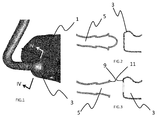
- Figure 1 shows a fuel tank 1 made of a plastic material, obtained by any known manufacturing process, such as an injection molding of two halves which are welded together to form an integral tank.
- a lateral wall of the tank comprises an embossment 3, also called "spud", for receiving a filler pipe 5.
- the filler pipe is usually obtained by blow molding of a parison made of a plastic material which is fuel impermeable, to an extent defined by legal requirements, either thanks to its thickness as a monolayer wall, or thanks to the presence of a fuel impermeable layer included in its multilayer wall.
- Figure 2 shows the filler pipe 5 obtained by blow molding in front of the embossment 3 of the tank 1. At this stage, these two elements do not show any opening and have to be cut to drill a hole along their longitudinal axis.
- Figure 3 shows the filler pipe 5 and the embossment 3 with their corresponding holes cut away, forming openings facing each other.
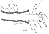
- Figure 4 is a longitudinal sectional view of the filler pipe 5 and embossment 3 along the cut plane IV-IV of figure 1 .
- the wall of the filler pipe 5 includes a fuel impermeable layer 7 located roughly in the middle of the thickness of the filler pipe wall, whereas the embossment 3 has a monolayer wall (without any included fuel impermeable layer).
- the filler pipe 5 and embossment 3 are welded together. The welding results from a hot plate welding process, carried out when approaching the filler pipe 5 close to the embossment 3 in the direction parallel to the longitudinal axis X-X of the filler pipe 5. During the welding, the plastic material of both elements 3-5 merge together to provide a continuous medium between the seat 9 of the filler pipe 5 and the seat 11 of the embossment ( figure 3 ).
- the fuel impermeable layer 7 of the filler pipe has a shape which prevents leaks at the welding between the tank and the filler pipe. This shape is designed when blow molding of the filler pipe, by anticipating the deformation of the seat 9 during welding to the tank.
- the sectional view of figure 4 also shows an inlet check valve 13 whose role is to prevent any flow of fuel in the upstream direction, opposed to the downstream filling direction, i.e. from the tank to the filler pipe.
- the inlet check valve 13 comprises a gate 15 at its downstream end 17 located inside the embossment 3.
- the opposed end of the inlet check valve, i.e. the upstream end 19, is equipped with petals 21. Depending on their shape, the petals 21 can sometimes be considered as teeth 21.
- the inlet check valve 13 is made of a circular tube 23 having a diameter slightly smaller than the diameter of the filler pipe 5. In other possible embodiments, the tube 23 has a cross section which is not circular.
- the petals 21 can be parts longitudinally cut in the wall of the tube 23, forming stripes extending parallel to the axis X-X and able to bend internally in a resilient way.
- the petals 21 urge against the internal wall of the filler pipe 5, at a location 5a where this internal wall is slightly conical.
- the petals 21 can adopt a shape similar to the shape of the internal wall of the filler pipe, which provides an almost continuous guiding for the flow of liquid going downstream in the filler pipe 5, in the direction of the tank 1.
- the tube 23 bears a conical skirt 25 which is connected to the tube 23 by a radial flange 27.
- the tube 23, radial flange 27 and conical skirt 25 can be one integral piece. In other embodiments, they can be separate elements linked together by any appropriate means.
- the conical skirt 25 ends with an edge 29 which can stick to or merge with the filler pipe wall when the latter is welded to the tank, making the edge 29 a seal part of the inlet check valve.
- the inlet check valve 13 comprises hook means which are embodied here by resilient tabs 31.
- the resilient tabs 31 are able to bend inwardly and unfold externally by resilience.
- the filler pipe 5 comprises a recess 33 in its internal wall for receiving the resilient tabs 31 in their unfolded position.
- the location of the recess 33 is determined so that when the resilient tabs 31 unfold in the recess, the conical skirt 25 rests against an internal conical 5b wall of the filler pipe.
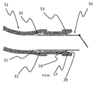
- Figure 4a illustrates a first step of insertion of the inlet check valve 13 inside the filler pipe 5.
- the direction of insertion is shown by arrow 35. This insertion direction is the upstream direction relative to the filler pipe.
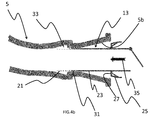
- the inlet check valve 13 is inserted through the end hole of the filler pipe with the petals 21 in front of the filler pipe. As shown on figure 4b , during insertion of the inlet check valve 13, the resilient tabs 31 bend inwardly and reduce their external diameter down to the diameter of the tube 23. Thus, the resilient tabs 31 can pass the first conical wall 5b of the filler pipe and reach the recess 33.
- the resilient tabs 31 When reaching the recess 33, as shown on figure 4c , the resilient tabs 31 unfold in the recess and their free ends abut against the bottom of the recess. Once unfolded, the resilient tabs 31 will not bend again inwardly, because there is no surface of the recess oriented to this end.
- the petals 31 fulfill a hook function, preventing the inlet check valve 13 from moving downstream, in the direction of the tank. In this position of the inlet check valve 13 in the filler pipe, the resilient tabs 31 are unfolded and the conical skirt 25 of the inlet check valve rests against the conical part 5b of the internal wall of the filler pipe.
- the inlet check valve 13 cannot move inside the filler pipe, neither upstream, nor downstream.
- the welding is carried out according to the well-known process of hot plate welding. As shown on figure 4 , the result of the welding is a merging of the materials of the two opposed seats 9 and 11, as well as merging of the edge 29 of the conical skirt 25, which forms a bead integral with the wall of the filler pipe.
- the shapes of the seats 9-11 and edge 29 are designed so that the result of the welding is optimized, as regards leaks at the junction between the fuel tank and the filler pipe.
- the filler pipe 5 and inlet check valve 13 are identical but the embossment 43 is made of a multilayer material including a fuel impermeable layer 45.
- the location of the fuel impermeable layer 45 in the embossment is obtained by an appropriate design of the mold used to form the embossment 43.
- the embossment 43 can be obtained with one half of the tank, by blow molding of a multilayer parison.
- the embossment 43 is cut to form the seat 11 and the opening facing the filler tank, at a location where the fuel impermeable layer 45 is close to the external face of the embossment. This improves the tightness of the welding in this example, but another choice can be done by the skilled person, depending on the global geometry of the tank and filler pipe.
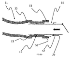
- the embossment 3 has the same shape as in figure 4 .
- the filler pipe 51 has a different shape because it does not comprise a first conical internal wall in the vicinity of the seat 9. It globally has a tubular shape from the internal recess 33 to the welding seat 9.
- the filler pipe 51 has an annular shoulder 53.
- the inlet check valve 55 also differs from the one of the previous figures in that it has a skirt 57 which is not conical but cylindrical.
- the skirt 57 is connected to the tube 23 by a radial flange 59.
- the location of the recess 33 in the filler pipe 51 is determined with the purpose that when the resilient tabs 31 of the inlet check valve 55 unfold inside the recess 33, the skirt 57 rests against the annular shoulder 53.
- the abutment of the inlet check valve in the filler pipe in the insertion direction i.e. in the upstream direction inside the filler pipe 51, results from the abutment of the radial flange 59 against the radial wall of the annular shoulder 53.
- the cylindrical skirt 57 ends with an edge 29 located in the vicinity of the end of the filler pipe when the inlet check valve is thus positioned in the filler pipe.
- Figures 6a , 6b and 6c illustrate three steps of insertion of the inlet check valve 55 inside the filler pipe 51.
- FIG 6a the inlet check valve is inserted with its petals 21 orientated in the direction of the filler pipe and the inlet check valve is moved in the direction indicated by the arrow 35, which is the upstream direction.
- Figure 6b illustrates an intermediate position of the inlet check valve 55 during its movement inside the filler pipe 51.
- the resilient tabs 31 bend inwardly to reach the diameter of the filler pipe and allow progression of the inlet check valve in the direction of the arrow 35.
- the filler pipe 51 can be held and welded to the tank through a usual hot plate welding process. During the welding, the plastic materials of the seats 9 and 11 and the plastic material of the edge 29 merge together to form an integral piece of plastic material, thus enabling a leak type fixation of the filler pipe to the tank.
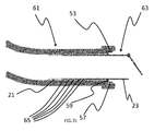
- the filler pipe 61 has a simpler shape: it is a cylindrical tube all along its length, without any internal recess, but at its end where it comprises an annular shoulder 53.
- the inlet check valve 63 consists in a tube 23, with an annular flange 59 and a cylindrical skirt 57.
- the inlet check valve 63 comprises teeth 65 forming hook means.
- the teeth 65 are made of a material the hardness of which is greater than the hardness of this material of the filler pipe wall. For instance, the ratio of these two harnesses is preferably superior to 40 %.
- the inlet check valve is inserted inside the filler pipe 61 in the direction indicated by the arrow 35.
- the teeth 65 slide on the internal wall of the filler pipe. Their hardness is higher than the hardness of the internal wall of the filler pipe but their form does not prevent the progression of the inlet check valve in the upstream direction, by scratching or scuffing the internal wall of the filler pipe, whereas the form of the teeth 65 would not allow a movement of the inlet check valve 63 in the opposite direction, i.e. downstream, because of the griping of the teeth 65 in the internal wall of the filler pipe.
- the inlet check valve 63 Once the inlet check valve 63 has reached his final position, as shown on figure 7c , the inlet check valve cannot move in both directions because it is blocked by the radial flange 59 resting against the annular shoulders 53 in the upstream direction and by the teeth 65 gripping the internal wall of the filler pipe 61 in the downstream direction.
- the filler pipe can then be welded to the tank without any need for holding the inlet check valve, because the latter is naturally positioned inside the filler pipe 61 and optimally located relative to the tank and to welding seats 9 and 11.
- the filler pipe is the same as in figures 6-6c , but the inlet check valve 71 has a different shape.
- Inlet check valve 71 is an integral part with different sections fulfilling the previously described means: petals 73, embossed section 75, tube 77. There is no radial flange, nor flange on this very simple inlet check valve.
- the wall of the inlet check valve is resiliently deformable, so that the embossed section 75 can reduce its diameter down to the diameter of the straight portion of the filler pipe, as shown on figure 8b , and recover its initial shape to fill the recess 33, as shown on figure 8c .
- the filler pipe and the fuel tank can both be multilayer structures.
Abstract
An inlet check valve intended to be entirely located within an internal volume delimited by a liquid tank of a vehicle and a filler pipe welded to the tank, the filler pipe defining a downstream direction, followed by a liquid filling the tank, and an upstream direction opposite to the downstream direction, the inlet check valve comprising a tube with an upstream end pointing toward the upstream direction and, at the upstream end, resilient means for adapting the form of the tube to the internal wall of the filler pipe, wherein the inlet check valve comprises hook means for securing the tube to an internal wall of the filler pipe and prevent the inlet check valve from moving within the filler pipe in the downstream direction.
Description
- The present invention relates to an inlet check valve for a filler pipe welded to a liquid tank of a vehicle.
- The terms "liquid tank" are intended to denote a sealed tank able to store liquid under diverse and varying environmental and usage conditions. An example of liquid tank is a fuel tank fitted to motor vehicles.
- The terms "filler pipe" are intended to denote a sealed pipe having two openings and through which fluid flows in order to fill a tank, in a downstream direction. The upstream direction in the filler pipe is the direction opposite to the downstream direction.
- Vehicles usually have many kinds of liquid tank on board, such as fuel tank, tank for urea storage, etc. These tanks are generally equipped with a filler pipe welded around an opening in a wall of the tank and through which the tank is filled. The inlet of the tank is preferably equipped with an inlet check valve to prevent the liquid flowing back to the filler pipe.
- The terms "inlet check valve" or "check valve", also called "clack valve", "non-return valve" or "one-way valve", are intended to denote a valve that normally allows liquid to flow through it in only one direction. The inlet check valve can be made of plastic or metal or a combination of plastic and metal.
- Various kinds of inlet check valve exist. The invention relates to a particular type of inlet check valve which is entirely located within an internal volume delimited by the tank and the filler pipe. With this type of inlet check valve, the access to the inlet check valve, once the filler pipe is in place on the tank, is no more possible.
- One known method for installing such an inlet check valve in the filler pipe consists in inserting the check valve into the filler pipe in the upstream direction, until it has reached an appropriate location in the filler pipe. The filler pipe is then welded to the tank. The inlet check valve has resilient means at its upstream end (the end of the valve pointing toward the upstream direction), for instance having the form of flexible lips or petals, for adapting the shape of the upstream end of the inlet check valve to the internal shape of the filler pipe and allow a continuous flow of liquid when filling the tank. The resilient means presses against the internal wall of the filler pipe, which is slightly conical at this location to ensure the adaptation of the resilient means.
- The inventors have identified a drawback of this method, which is that the check valve is not stably positioned in the filler pipe. Indeed, while pressing against the internal conical wall of the filler pipe, the resilient means act like a spring and tend to push the inlet check valve out of the filler pipe in the downstream direction. The inlet check valve is stopped by the tank and cannot move too far, thanks to an annular flange of the inlet check valve butting against the tank. But the inventors have noticed that the pushing of the inlet check valve against the tank, because of the resilient means, creates a counterforce applied to the filler pipe during welding of the filler pipe to the tank wall. Because of this counterforce, the force applied to the filler pipe during its welding to the tank is not entirely dedicated to merging the melted materials. One portion of this force is counterbalanced by the pushing of the inlet check valve and the remaining part of the force used for the welding is not controlled.
- Consequently, it is difficult to guarantee a good positioning of the filler pipe around the opening of the tank during the welding, as well as the quality of the welding. In particular, if the pushing of the inlet check valve on the filler pipe is not rotationally symmetric, the filler pipe may imperceptibly misalign or tilt. The consequences of such misalignment of misorientation are multiple, such as poor mechanical weld, leak, malfunction of the fuel filling due to the bad orientation of the inlet check valve, etc. In practice, the welding is tested and the tank is scrapped if it does not meet the expectations.
- It is therefore an object of the invention to provide an inlet check valve arranged in the filler pipe which does not disturb the welding of the filler pipe to the tank wall and which does not demonstrate the above drawbacks.
- The invention relates to an inlet check valve for a filler pipe weldable to a liquid tank of a vehicle, the inlet check valve being adapted to be arranged entirely within an internal volume delimited by the liquid tank and the filler pipe, the inlet check valve being configured to allow liquid travelling through the filler pipe in a downstream direction to enter the liquid tank, the inlet check valve comprising a tube having an upstream end pointing toward an upstream direction opposite to the downstream direction, the upstream end of the tube comprising resilient means being adapted to conform to a portion of the internal wall of the filler pipe, wherein the inlet check valve comprises hook means for securing the tube to another portion of the internal wall of the filler pipe and prevent the inlet check valve from moving within the filler pipe in the downstream direction.
- In other words, the inlet check valve is intended to be entirely located within an internal volume delimited by a liquid tank of a vehicle and a filler pipe welded to the tank, the filler pipe defines a downstream direction, followed by a liquid filling the tank, and an upstream direction opposite to the downstream direction. The inlet check valve comprises a tube with an upstream end pointing toward the upstream direction and, at the upstream end, resilient means for adapting the form of the tube to the internal wall of the filler pipe. The inlet check valve comprises hook means for securing the tube to an internal wall of the filler pipe and prevent the inlet check valve from moving within the filler pipe in the downstream direction.
- The hook means denote any means which are able to stably secure the tube to the internal wall of the filler pipe and prevent any movement of the inlet check valve inside the filler pipe which brings the valve closer to the tank. The stable securing prevents the inlet check valve from applying to the tank the counterforce generated by its resilient means pressing against the internal wall of the filler pipe. Therefore, the force applied to the filler pipe for its welding to the tank is entirely dedicated to the welding, which ensures a good positioning of the filler piper against the tank and secures the quality of the welding.
- The inlet check valve can be partially or entirely located within the filler pipe. If it is not entirely inside the filler pipe, then it has a portion protruding in the tank.
- The hooks means is made of metal or plastic or any other suitable material.
- The welding area of filler pipe is made of a material which is compatible with the material of the welding area of the tank. Preferably, the filler pipe has a layer made of a material which is chemically compatible with a layer of the tank.
- The resilient means preferably ensure the continuity of the tube to the internal wall of the filler pipe in order to guarantee a continuous flow or at least an unperturbed flow of liquid from the inlet of the filler pipe until the inside of the tank.
- According to one advantageous embodiment of the invention, the hook means are resilient tabs able to bend inwardly when the inlet check valve is inserted upstream in the filler pipe and unfold outwardly when reaching a recess provided for in the internal wall of the filler pipe. The hook means can be resilient enough to be folded while the inlet check valve is pushed within the filler pipe but also rigid enough to resist from folding again while they are pressed against the recess, so that they are able to block the entire check valve from moving in the downstream direction. They preferably point toward the tank, i.e. the downstream direction, in both fold and unfold positions.
- According to an advantageous embodiment, the hook means are teeth made of a material the hardness of which is greater than the hardness of the material the filler pipe is made of. The teeth, having a greater hardness, are able to grip the internal wall of the filler pipe and to resist from a force pushing them in the downstream direction.
- According to another advantageous embodiment, the inlet check valve comprises an abutment at its downstream end, preventing the inlet check valve from moving in the upstream direction once it has reached its target location in the filler pipe. Thus, the inlet check valve is blocked in both directions by means of the abutment and the hook means in the targeted location.
- Advantageously, the abutment is located on a seal part adapted to be welded to the filler pipe or to the tank during welding of the filler pipe to the tank. When the inlet check valve is secured in the targeted location, the seal part is in contact with the downstream end of the filler pipe or with the internal wall of the tank, in the vicinity of the weld area. Thus, when the contact zone between the filler pipe and the tank is heated to melt the material for welding, the seal part is also heated until being welded to the tank or to the filler pipe. The seal part is preferably made of a material which is chemically compatible with the material of the tank and the filler pipe of the welding area.
- Advantageously, the abutment is intended to match with the internal wall of the filler pipe, for example by way of a recess, a shoulder or a locally reduced internal diameter of the filler pipe.
- Advantageously, the abutment has a conical shape.
- Alternatively, the abutment is a projection which protrudes from an external surface of the inlet check valve.
- The present invention also relates to a set of a filler pipe which is to be welded to a liquid tank of a vehicle and an inlet check valve previously described.
- According to an embodiment of the invention, the internal wall of the filler pipe has a recess for receiving the hook means of the inlet check valve where the inlet check valve is in its target location within the filler pipe.
- According to another embodiment of the invention, the filler pipe is made of a multilayer plastic material having a fuel impermeable layer. The impermeable layer is preferably a layer of a resin impermeable to the fuel, such as EVOH for example (a copolymer of ethylene and partially hydrolyzed vinyl acetate).
- According to an embodiment of the invention, the filler pipe has a treated external surface (by fluoration or sulphonation) which renders the filler pipe impermeable to fuel.
- According to an embodiment of the invention, the liquid tank is a fuel tank made of a multilayer plastic material having a fuel impermeable layer.
- According to an embodiment of the invention, the liquid tank is a fuel tank having a treated external surface (by fluoration or sulphonation) which renders the tank impermeable to fuel.
- The present invention also relates to an assembly composed of a liquid tank of a vehicle and of the set previously described, the filler pipe being welded to the tank.
- According to an embodiment of the invention, in the assembly, the inlet check valve is also welded to the tank.
- The liquid tank and the filler pipe according to the invention are preferably made of plastic, that is to say, of a material comprising at least one synthetic resin polymer. All types of plastic may be suitable. Particularly suitable plastics come from the thermoplastic category. The term "thermoplastic" denotes any thermoplastic polymer including thermoplastic elastomers, as well as blends thereof. The term "polymer" denotes both homopolymers and copolymers (especially binary or ternary copolymers). Examples of such copolymers are, non-limitingly, random copolymers, linear block copolymers, other block copolymers and graft copolymers. One polymer which is often used is polyethylene. Excellent results have been obtained with high density polyethylene (HDPE).
- The invention will be better understood through the following figures which illustrate certain practical aspects of the invention. The figures are only shown as examples and do not limit the scope of the present invention.
-
Figure 1 is a global view of a tank with a filler pipe welded thereon. -
Figure 2 shows a section of one end of the filler pipe and a part of the tank receiving the filler piper, just after molding. -
Figure 3 is similar tofigure 2 , but the filler pipe and the tank part have been cut before assembling. -
Figure 4 is a longitudinal sectional view of an assembly of a liquid tank and a set of a filler pipe and an inlet check valve according to a first embodiment of the invention. -
Figure 4a is a longitudinal sectional view of the set of the filler pipe and the inlet check valve offigure 4 , before being assembled. -
Figure 4b is a longitudinal sectional view of the set offigure 4 while being assembled. -
Figure 4c is a longitudinal sectional view of the set offigure 4 , once assembled. -
Figure 5 is a longitudinal sectional view of an assembly, similar to the one offigure 4 , of a liquid tank and a set of a filler pipe and an inlet check valve according to a second embodiment of the invention. -
Figure 6 is a longitudinal sectional view of an assembly, similar to the one offigure 4 , of a liquid tank and a set of a filler pipe and an inlet check valve according to a third embodiment of the invention. -
Figure 6a is a longitudinal sectional view of the set of the filler pipe and the inlet check valve offigure 7 , before being assembled. -
Figure 6b is a longitudinal sectional view of the set offigure 7 while being assembled. -
Figure 6c is a longitudinal sectional view of the set offigure 7 , once assembled. -
Figure 7a is a longitudinal sectional view of a set of a filler pipe and an inlet check valve according to a fourth embodiment of the invention, before being assembled. -
Figure 7b is a view similar tofigure 7a , during assembling of the set. -
Figure 7c is a view similar tofigure 7a , the set being assembled. -
Figure 8a is a longitudinal sectional view of a set of a filler pipe and an inlet check valve according to a fifth embodiment of the invention, before being assembled. -
Figure 8b is a view similar tofigure 8a , during assembling of the set. -
Figure 8c is a view similar tofigure 8a , the set being assembled. - Now, we refer to
figure 1 . -
Figure 1 shows afuel tank 1 made of a plastic material, obtained by any known manufacturing process, such as an injection molding of two halves which are welded together to form an integral tank. As represented onfigure 1 , a lateral wall of the tank comprises anembossment 3, also called "spud", for receiving afiller pipe 5. The filler pipe is usually obtained by blow molding of a parison made of a plastic material which is fuel impermeable, to an extent defined by legal requirements, either thanks to its thickness as a monolayer wall, or thanks to the presence of a fuel impermeable layer included in its multilayer wall. -
Figure 2 shows thefiller pipe 5 obtained by blow molding in front of theembossment 3 of thetank 1. At this stage, these two elements do not show any opening and have to be cut to drill a hole along their longitudinal axis.Figure 3 shows thefiller pipe 5 and theembossment 3 with their corresponding holes cut away, forming openings facing each other. -
Figure 4 is a longitudinal sectional view of thefiller pipe 5 andembossment 3 along the cut plane IV-IV offigure 1 . The wall of thefiller pipe 5 includes a fuelimpermeable layer 7 located roughly in the middle of the thickness of the filler pipe wall, whereas theembossment 3 has a monolayer wall (without any included fuel impermeable layer). Thefiller pipe 5 andembossment 3 are welded together. The welding results from a hot plate welding process, carried out when approaching thefiller pipe 5 close to theembossment 3 in the direction parallel to the longitudinal axis X-X of thefiller pipe 5. During the welding, the plastic material of both elements 3-5 merge together to provide a continuous medium between the seat 9 of thefiller pipe 5 and theseat 11 of the embossment (figure 3 ). - The fuel
impermeable layer 7 of the filler pipe has a shape which prevents leaks at the welding between the tank and the filler pipe. This shape is designed when blow molding of the filler pipe, by anticipating the deformation of the seat 9 during welding to the tank. - The sectional view of
figure 4 also shows aninlet check valve 13 whose role is to prevent any flow of fuel in the upstream direction, opposed to the downstream filling direction, i.e. from the tank to the filler pipe. To that purpose, theinlet check valve 13 comprises agate 15 at itsdownstream end 17 located inside theembossment 3. The opposed end of the inlet check valve, i.e. theupstream end 19, is equipped withpetals 21. Depending on their shape, thepetals 21 can sometimes be considered asteeth 21. Between itsupstream end 19 and itsdownstream end 17, theinlet check valve 13 is made of acircular tube 23 having a diameter slightly smaller than the diameter of thefiller pipe 5. In other possible embodiments, thetube 23 has a cross section which is not circular. - The
petals 21 can be parts longitudinally cut in the wall of thetube 23, forming stripes extending parallel to the axis X-X and able to bend internally in a resilient way. Thepetals 21 urge against the internal wall of thefiller pipe 5, at alocation 5a where this internal wall is slightly conical. Thus, thepetals 21 can adopt a shape similar to the shape of the internal wall of the filler pipe, which provides an almost continuous guiding for the flow of liquid going downstream in thefiller pipe 5, in the direction of thetank 1. - In this embodiment, the
tube 23 bears aconical skirt 25 which is connected to thetube 23 by aradial flange 27. Thetube 23,radial flange 27 andconical skirt 25 can be one integral piece. In other embodiments, they can be separate elements linked together by any appropriate means. In the direction of the tank, theconical skirt 25 ends with anedge 29 which can stick to or merge with the filler pipe wall when the latter is welded to the tank, making the edge 29 a seal part of the inlet check valve. - In the vicinity of the
petals 21, i.e. close to theupstream end 19, theinlet check valve 13 comprises hook means which are embodied here byresilient tabs 31. Theresilient tabs 31 are able to bend inwardly and unfold externally by resilience. - We can see on
figure 4 that thefiller pipe 5 comprises arecess 33 in its internal wall for receiving theresilient tabs 31 in their unfolded position. The location of therecess 33 is determined so that when theresilient tabs 31 unfold in the recess, theconical skirt 25 rests against an internal conical 5b wall of the filler pipe. -
Figure 4a illustrates a first step of insertion of theinlet check valve 13 inside thefiller pipe 5. The direction of insertion is shown byarrow 35. This insertion direction is the upstream direction relative to the filler pipe. - The
inlet check valve 13 is inserted through the end hole of the filler pipe with thepetals 21 in front of the filler pipe. As shown onfigure 4b , during insertion of theinlet check valve 13, theresilient tabs 31 bend inwardly and reduce their external diameter down to the diameter of thetube 23. Thus, theresilient tabs 31 can pass the firstconical wall 5b of the filler pipe and reach therecess 33. - When reaching the
recess 33, as shown onfigure 4c , theresilient tabs 31 unfold in the recess and their free ends abut against the bottom of the recess. Once unfolded, theresilient tabs 31 will not bend again inwardly, because there is no surface of the recess oriented to this end. To the opposite, thepetals 31 fulfill a hook function, preventing theinlet check valve 13 from moving downstream, in the direction of the tank. In this position of theinlet check valve 13 in the filler pipe, theresilient tabs 31 are unfolded and theconical skirt 25 of the inlet check valve rests against theconical part 5b of the internal wall of the filler pipe. - The
inlet check valve 13 cannot move inside the filler pipe, neither upstream, nor downstream. - Thanks to this kind of fixation of the inlet check valve in the
filler pipe 5, it is possible to manipulate thefiller pipe 5 and to approach said filler pipe close to the tank and to weld together theopposed seats 9 and 11 of these two elements. - The welding is carried out according to the well-known process of hot plate welding. As shown on
figure 4 , the result of the welding is a merging of the materials of the twoopposed seats 9 and 11, as well as merging of theedge 29 of theconical skirt 25, which forms a bead integral with the wall of the filler pipe. - The shapes of the seats 9-11 and
edge 29 are designed so that the result of the welding is optimized, as regards leaks at the junction between the fuel tank and the filler pipe. - In the embodiment of
figure 5 , thefiller pipe 5 andinlet check valve 13 are identical but theembossment 43 is made of a multilayer material including a fuelimpermeable layer 45. The location of the fuelimpermeable layer 45 in the embossment is obtained by an appropriate design of the mold used to form theembossment 43. In this case, theembossment 43 can be obtained with one half of the tank, by blow molding of a multilayer parison. Theembossment 43 is cut to form theseat 11 and the opening facing the filler tank, at a location where the fuelimpermeable layer 45 is close to the external face of the embossment. This improves the tightness of the welding in this example, but another choice can be done by the skilled person, depending on the global geometry of the tank and filler pipe. - In the embodiment of
figure 6 , theembossment 3 has the same shape as infigure 4 . Thefiller pipe 51 has a different shape because it does not comprise a first conical internal wall in the vicinity of the seat 9. It globally has a tubular shape from theinternal recess 33 to the welding seat 9. - Instead of a conical part, the
filler pipe 51 has anannular shoulder 53. - The
inlet check valve 55 also differs from the one of the previous figures in that it has askirt 57 which is not conical but cylindrical. Theskirt 57 is connected to thetube 23 by aradial flange 59. - As in the previous embodiments, the location of the
recess 33 in thefiller pipe 51 is determined with the purpose that when theresilient tabs 31 of theinlet check valve 55 unfold inside therecess 33, theskirt 57 rests against theannular shoulder 53. In this embodiment, the abutment of the inlet check valve in the filler pipe in the insertion direction, i.e. in the upstream direction inside thefiller pipe 51, results from the abutment of theradial flange 59 against the radial wall of theannular shoulder 53. - The
cylindrical skirt 57 ends with anedge 29 located in the vicinity of the end of the filler pipe when the inlet check valve is thus positioned in the filler pipe. -
Figures 6a ,6b and6c illustrate three steps of insertion of theinlet check valve 55 inside thefiller pipe 51. - In
figure 6a , the inlet check valve is inserted with itspetals 21 orientated in the direction of the filler pipe and the inlet check valve is moved in the direction indicated by thearrow 35, which is the upstream direction.Figure 6b illustrates an intermediate position of theinlet check valve 55 during its movement inside thefiller pipe 51. Theresilient tabs 31 bend inwardly to reach the diameter of the filler pipe and allow progression of the inlet check valve in the direction of thearrow 35. - On
figure 6c , theradial flange 27 has reached the radial wall of theshoulder 53. This abutment stops the progression of the inlet check valve and theresilient tabs 31 have reached therecess 33 and unfold externally to block theinlet check valve 55 in the downstream direction. Theinlet check valve 55 is thus affixed inside thefiller pipe 51 with thepetals 21 urging against the internal wall of thefiller pipe 51. - As already explained, once the inlet check valve has been affixed inside the
filler pipe 51, thefiller pipe 51 can be held and welded to the tank through a usual hot plate welding process. During the welding, the plastic materials of theseats 9 and 11 and the plastic material of theedge 29 merge together to form an integral piece of plastic material, thus enabling a leak type fixation of the filler pipe to the tank. - In the embodiment of
figures 7a-7c , thefiller pipe 61 has a simpler shape: it is a cylindrical tube all along its length, without any internal recess, but at its end where it comprises anannular shoulder 53. - The
inlet check valve 63 consists in atube 23, with anannular flange 59 and acylindrical skirt 57. Instead of the resilient tabs of the preceding embodiments, theinlet check valve 63 comprisesteeth 65 forming hook means. Theteeth 65 are made of a material the hardness of which is greater than the hardness of this material of the filler pipe wall. For instance, the ratio of these two harnesses is preferably superior to 40 %. - As shown on
figure 7a , the inlet check valve is inserted inside thefiller pipe 61 in the direction indicated by thearrow 35. During insertion, as shown onfigure 7b , theteeth 65 slide on the internal wall of the filler pipe. Their hardness is higher than the hardness of the internal wall of the filler pipe but their form does not prevent the progression of the inlet check valve in the upstream direction, by scratching or scuffing the internal wall of the filler pipe, whereas the form of theteeth 65 would not allow a movement of theinlet check valve 63 in the opposite direction, i.e. downstream, because of the griping of theteeth 65 in the internal wall of the filler pipe. - Once the
inlet check valve 63 has reached his final position, as shown onfigure 7c , the inlet check valve cannot move in both directions because it is blocked by theradial flange 59 resting against theannular shoulders 53 in the upstream direction and by theteeth 65 gripping the internal wall of thefiller pipe 61 in the downstream direction. - As in the preceding embodiments, the filler pipe can then be welded to the tank without any need for holding the inlet check valve, because the latter is naturally positioned inside the
filler pipe 61 and optimally located relative to the tank and towelding seats 9 and 11. - In the embodiment of
figures 8a-8c , the filler pipe is the same as infigures 6-6c , but theinlet check valve 71 has a different shape.Inlet check valve 71 is an integral part with different sections fulfilling the previously described means:petals 73, embossedsection 75,tube 77. There is no radial flange, nor flange on this very simple inlet check valve. - The wall of the inlet check valve is resiliently deformable, so that the embossed
section 75 can reduce its diameter down to the diameter of the straight portion of the filler pipe, as shown onfigure 8b , and recover its initial shape to fill therecess 33, as shown onfigure 8c . - The invention is not limited to the above embodiments and other embodiments exist and will appear clearly to one skilled in the art. For example, the filler pipe and the fuel tank can both be multilayer structures.
-
-
FIGS 1-4c
Fuel tank 1
Embossment 3
Filler pipe 5
Plan IV-IV surfigure 1
Fuelimpermeable layer 7 of thefiller pipe 5
Seat 9 filler pipe
Seat 11 of the embossment
Inlet check valve 13
Gate 15
Downstream end 17 of the ICV
Upstream end 19 of the ICV
Teeth 21 (or petals)
Tube 23
Conical skirt 25
Radial flange 27
Edge 29 of the skirt
Resilient tabs 31
Recess 33
Arrow 35 -
FIG.5
Embossment 43
Fuel impermeable layer 45 (embossment 43) -
FIG.6
Filler pipe 51
Annular shoulder 53
Inlet check valve 55
Cylindrical skirt 57
Radial flange 59 -
FIG.7-7c
Filler pipe 61
Inlet check valve 63
Teeth 65 -
FIGS 8a-8c
Inlet check valve 71
Petals 73
Embossed section 75
Tube 77
Claims (11)
- An inlet check valve for a filler pipe weldable to a liquid tank of a vehicle, the inlet check valve being adapted to be arranged entirely within an internal volume delimited by the liquid tank and the filler pipe, the inlet check valve being configured to allow liquid travelling through the filler pipe in a downstream direction to enter the liquid tank, the inlet check valve comprising a tube having an upstream end pointing toward an upstream direction opposite to the downstream direction, the upstream end of the tube comprising resilient means being adapted to conform to a portion of the internal wall of the filler pipe, wherein the inlet check valve comprises hook means for securing the tube to another portion of the internal wall of the filler pipe and prevent the inlet check valve from moving within the filler pipe in the downstream direction.
- The inlet check valve according to claim 1, wherein the hook means are resilient tabs able to bend inwardly when the inlet check valve is inserted in the filler pipe and unfold outwardly when reaching a recess provided for in the internal wall of the filler pipe.
- The inlet check valve according to claim 1, wherein the hook means are teeth made of a material, the hardness of which is greater than the hardness of the material the filler pipe is made of.
- The inlet check valve according to any one of preceding claims, wherein the inlet check valve comprises an abutment at its downstream end, preventing the inlet check valve from moving in the upstream direction once it has reached its target location in the filler pipe.
- The inlet check valve according to claim 4, wherein the abutment is located on a seal part adapted to be welded to the filler pipe or to the tank during welding of the filler pipe to the tank.
- The inlet check valve according to any one of claims 4 and 5, wherein the abutment has a conical shape.
- A set of a filler pipe which is to be welded to a liquid tank of a vehicle and of an inlet check valve according to any one of claims 1 to 6.
- The set according to claim 7, wherein the internal wall of the filler pipe has a recess for receiving the hook means of the inlet check valve where the inlet check valve is in its target location within the filler pipe.
- The set according to any one of claims 7 and 8, wherein the filler pipe is made of a multilayer plastic material having a fuel impermeable layer.
- An assembly composed of a liquid tank of a vehicle and of a set according to any one of claims 7, 8 and 9, wherein the filler pipe is welded to the tank.
- The assembly according to claim 10, wherein the inlet check valve is also welded to the tank.
Priority Applications (5)
| Application Number | Priority Date | Filing Date | Title |
|---|---|---|---|
| EP15306253.4A EP3124306A1 (en) | 2015-07-31 | 2015-07-31 | An inlet check valve for a filler pipe welded to a liquid tank |
| PCT/EP2016/067299 WO2017021151A1 (en) | 2015-07-31 | 2016-07-20 | An inlet check valve for a filler pipe welded to a liquid tank |
| US15/746,999 US10434873B2 (en) | 2015-07-31 | 2016-07-20 | Inlet check valve for a filler pipe welded to a liquid tank |
| CN201680042160.XA CN107848408B (en) | 2015-07-31 | 2016-07-20 | Inlet check valve for a fill tube welded to a liquid tank |
| EP16741624.7A EP3328673B1 (en) | 2015-07-31 | 2016-07-20 | An inlet check valve for a filler pipe welded to a liquid tank |
Applications Claiming Priority (1)
| Application Number | Priority Date | Filing Date | Title |
|---|---|---|---|
| EP15306253.4A EP3124306A1 (en) | 2015-07-31 | 2015-07-31 | An inlet check valve for a filler pipe welded to a liquid tank |
Publications (1)
| Publication Number | Publication Date |
|---|---|
| EP3124306A1 true EP3124306A1 (en) | 2017-02-01 |
Family
ID=53794175
Family Applications (2)
| Application Number | Title | Priority Date | Filing Date |
|---|---|---|---|
| EP15306253.4A Withdrawn EP3124306A1 (en) | 2015-07-31 | 2015-07-31 | An inlet check valve for a filler pipe welded to a liquid tank |
| EP16741624.7A Active EP3328673B1 (en) | 2015-07-31 | 2016-07-20 | An inlet check valve for a filler pipe welded to a liquid tank |
Family Applications After (1)
| Application Number | Title | Priority Date | Filing Date |
|---|---|---|---|
| EP16741624.7A Active EP3328673B1 (en) | 2015-07-31 | 2016-07-20 | An inlet check valve for a filler pipe welded to a liquid tank |
Country Status (4)
| Country | Link |
|---|---|
| US (1) | US10434873B2 (en) |
| EP (2) | EP3124306A1 (en) |
| CN (1) | CN107848408B (en) |
| WO (1) | WO2017021151A1 (en) |
Citations (6)
| Publication number | Priority date | Publication date | Assignee | Title |
|---|---|---|---|---|
| JP2004124903A (en) * | 2002-10-07 | 2004-04-22 | Yachiyo Industry Co Ltd | Tube connection port of fuel tank |
| JP2004345365A (en) * | 2003-03-24 | 2004-12-09 | Yachiyo Industry Co Ltd | Component of resin fuel tank |
| DE102008005717A1 (en) * | 2007-11-13 | 2009-02-26 | Alfmeier Präzision AG Baugruppen und Systemlösungen | Fuel tank for motor vehicle, has filler pipe and filler neck head connected with its free end and blocking devices are arranged partially in area of access openings provided at overlapping area |
| US20100194104A1 (en) * | 2009-02-03 | 2010-08-05 | Hennemann Thomas L | Male push lock pipe connection system |
| JP2010236567A (en) * | 2009-03-30 | 2010-10-21 | Togawa Rubber Co Ltd | Hose joint |
| FR2997472A1 (en) * | 2012-10-26 | 2014-05-02 | Comap | Tubular connection unit, has locking spacer comprising abutment portion that is arranged against leg, and exerting support by abutment portion against leg to hold fastening units when bearing surface is subjected to pressurize fluid |
Family Cites Families (15)
| Publication number | Priority date | Publication date | Assignee | Title |
|---|---|---|---|---|
| EP0840051B1 (en) * | 1992-05-29 | 2001-03-21 | Tokai Rubber Industries, Ltd. | Hose connecting structure |
| DE19819779A1 (en) * | 1998-05-04 | 1999-11-11 | Mannesmann Vdo Ag | Fuel tank |
| JP4026322B2 (en) * | 2001-03-01 | 2007-12-26 | 豊田合成株式会社 | Manufacturing method of welded joint for fuel tank |
| JP2002339825A (en) * | 2001-03-16 | 2002-11-27 | Tokai Rubber Ind Ltd | Cylindrical body installing structure to fuel tank |
| US20030116202A1 (en) * | 2001-12-21 | 2003-06-26 | Eaton Corporation | Assembling a siphonable filler tube with a check vlave on a fuel tank |
| US7128346B2 (en) * | 2002-03-15 | 2006-10-31 | Tokai Rubber Industries, Ltd. | Structure for connecting tubular member to fuel tank |
| US7565986B2 (en) * | 2003-12-02 | 2009-07-28 | Ti Group Automotive Systems, L.L.C. | Fuel system component and method of manufacture |
| US7704440B2 (en) * | 2003-12-02 | 2010-04-27 | Ti Group Automotive Systems, L.L.C. | Fuel system component and method of manufacture |
| JP2006143172A (en) * | 2004-10-22 | 2006-06-08 | Tokai Rubber Ind Ltd | Welding joint in fuel tank |
| JP2007008352A (en) * | 2005-06-30 | 2007-01-18 | Tokai Rubber Ind Ltd | Welding joint of fuel tank |
| JP4937236B2 (en) * | 2008-11-26 | 2012-05-23 | 株式会社ニフコ | Fuel tank connector and check valve |
| US8342579B2 (en) * | 2009-02-03 | 2013-01-01 | Hennemann Thomas L | Push lock pipe connection system |
| US8701694B2 (en) * | 2011-03-10 | 2014-04-22 | Stant Usa Corp. | Mount for inlet check valve |
| US20120228292A1 (en) * | 2011-03-10 | 2012-09-13 | Stant Usa Corp. | Mount for inlet check valve |
| JP5797690B2 (en) * | 2013-05-29 | 2015-10-21 | 八千代工業株式会社 | Filler pipe mounting method and filler pipe mounting structure |
-
2015
- 2015-07-31 EP EP15306253.4A patent/EP3124306A1/en not_active Withdrawn
-
2016
- 2016-07-20 EP EP16741624.7A patent/EP3328673B1/en active Active
- 2016-07-20 CN CN201680042160.XA patent/CN107848408B/en active Active
- 2016-07-20 US US15/746,999 patent/US10434873B2/en active Active
- 2016-07-20 WO PCT/EP2016/067299 patent/WO2017021151A1/en active Application Filing
Patent Citations (6)
| Publication number | Priority date | Publication date | Assignee | Title |
|---|---|---|---|---|
| JP2004124903A (en) * | 2002-10-07 | 2004-04-22 | Yachiyo Industry Co Ltd | Tube connection port of fuel tank |
| JP2004345365A (en) * | 2003-03-24 | 2004-12-09 | Yachiyo Industry Co Ltd | Component of resin fuel tank |
| DE102008005717A1 (en) * | 2007-11-13 | 2009-02-26 | Alfmeier Präzision AG Baugruppen und Systemlösungen | Fuel tank for motor vehicle, has filler pipe and filler neck head connected with its free end and blocking devices are arranged partially in area of access openings provided at overlapping area |
| US20100194104A1 (en) * | 2009-02-03 | 2010-08-05 | Hennemann Thomas L | Male push lock pipe connection system |
| JP2010236567A (en) * | 2009-03-30 | 2010-10-21 | Togawa Rubber Co Ltd | Hose joint |
| FR2997472A1 (en) * | 2012-10-26 | 2014-05-02 | Comap | Tubular connection unit, has locking spacer comprising abutment portion that is arranged against leg, and exerting support by abutment portion against leg to hold fastening units when bearing surface is subjected to pressurize fluid |
Also Published As
| Publication number | Publication date |
|---|---|
| US20180215253A1 (en) | 2018-08-02 |
| EP3328673A1 (en) | 2018-06-06 |
| CN107848408A (en) | 2018-03-27 |
| WO2017021151A1 (en) | 2017-02-09 |
| US10434873B2 (en) | 2019-10-08 |
| EP3328673B1 (en) | 2019-12-11 |
| CN107848408B (en) | 2021-02-12 |
Similar Documents
| Publication | Publication Date | Title |
|---|---|---|
| EP1211196B1 (en) | Container with fitting and method for forming the same | |
| US7014214B2 (en) | Resinous connector | |
| EP2777971B1 (en) | Exhaust valve device for fuel tank | |
| JP6710058B2 (en) | Filler tube and manufacturing method thereof | |
| US11318683B2 (en) | Connection structure of resin tube and resin joint and connection method thereof | |
| US20150239198A1 (en) | Attaching structure of insert member to blow molded article | |
| CN107921863B (en) | Liquid vehicle tank comprising a fastened component | |
| KR20200044052A (en) | Automotive liquid container and its injection molding method | |
| US6808209B2 (en) | Attachment to be attached to fuel tank | |
| EP3328673B1 (en) | An inlet check valve for a filler pipe welded to a liquid tank | |
| JP2014046676A (en) | Attachment structure for insert member of blow molding item | |
| US20200298696A1 (en) | Blow molded support for inlet check valve | |
| JP2009137488A (en) | Fuel tank | |
| JP6788939B2 (en) | How to install the filler pipe | |
| JP2014104693A (en) | Fitting structure of insert member of blow molded part | |
| JP2015030117A (en) | Insert member fitting structure of blow-molded product | |
| JP2006123576A (en) | Fuel check valve | |
| JP2008168766A (en) | Nipple fixing structure for fuel tank | |
| JP2005199885A (en) | Synthetic resin hollow body, fuel tank for automobile, and its manufacturing | |
| JP2004345365A (en) | Component of resin fuel tank | |
| JP6359844B2 (en) | Fuel tank parts welding equipment | |
| CN109552032B (en) | Check valve for fuel tank | |
| JP2021138252A (en) | Connection structure | |
| JP2016117259A (en) | Fitting structure and fitting method of insert member of blow molding article | |
| US20070209733A1 (en) | High flow fuel inlet pipe |
Legal Events
| Date | Code | Title | Description |
|---|---|---|---|
| PUAI | Public reference made under article 153(3) epc to a published international application that has entered the european phase |
Free format text: ORIGINAL CODE: 0009012 |
|
| AK | Designated contracting states |
Kind code of ref document: A1 Designated state(s): AL AT BE BG CH CY CZ DE DK EE ES FI FR GB GR HR HU IE IS IT LI LT LU LV MC MK MT NL NO PL PT RO RS SE SI SK SM TR |
|
| AX | Request for extension of the european patent |
Extension state: BA ME |
|
| STAA | Information on the status of an ep patent application or granted ep patent |
Free format text: STATUS: THE APPLICATION IS DEEMED TO BE WITHDRAWN |
|
| 18D | Application deemed to be withdrawn |
Effective date: 20170802 |