EP3125020A1 - Small diameter inlays - Google Patents
Small diameter inlays Download PDFInfo
- Publication number
- EP3125020A1 EP3125020A1 EP16177295.9A EP16177295A EP3125020A1 EP 3125020 A1 EP3125020 A1 EP 3125020A1 EP 16177295 A EP16177295 A EP 16177295A EP 3125020 A1 EP3125020 A1 EP 3125020A1
- Authority
- EP
- European Patent Office
- Prior art keywords
- inlay
- cornea
- diameter
- corneal surface
- zone
- Prior art date
- Legal status (The legal status is an assumption and is not a legal conclusion. Google has not performed a legal analysis and makes no representation as to the accuracy of the status listed.)
- Withdrawn
Links
- 0 C1CC*CC1 Chemical compound C1CC*CC1 0.000 description 1
Images


Classifications
-
- A—HUMAN NECESSITIES
- A61—MEDICAL OR VETERINARY SCIENCE; HYGIENE
- A61F—FILTERS IMPLANTABLE INTO BLOOD VESSELS; PROSTHESES; DEVICES PROVIDING PATENCY TO, OR PREVENTING COLLAPSING OF, TUBULAR STRUCTURES OF THE BODY, e.g. STENTS; ORTHOPAEDIC, NURSING OR CONTRACEPTIVE DEVICES; FOMENTATION; TREATMENT OR PROTECTION OF EYES OR EARS; BANDAGES, DRESSINGS OR ABSORBENT PADS; FIRST-AID KITS
- A61F2/00—Filters implantable into blood vessels; Prostheses, i.e. artificial substitutes or replacements for parts of the body; Appliances for connecting them with the body; Devices providing patency to, or preventing collapsing of, tubular structures of the body, e.g. stents
- A61F2/02—Prostheses implantable into the body
- A61F2/14—Eye parts, e.g. lenses, corneal implants; Implanting instruments specially adapted therefor; Artificial eyes
- A61F2/147—Implants to be inserted in the stroma for refractive correction, e.g. ring-like implants
-
- A—HUMAN NECESSITIES
- A61—MEDICAL OR VETERINARY SCIENCE; HYGIENE
- A61F—FILTERS IMPLANTABLE INTO BLOOD VESSELS; PROSTHESES; DEVICES PROVIDING PATENCY TO, OR PREVENTING COLLAPSING OF, TUBULAR STRUCTURES OF THE BODY, e.g. STENTS; ORTHOPAEDIC, NURSING OR CONTRACEPTIVE DEVICES; FOMENTATION; TREATMENT OR PROTECTION OF EYES OR EARS; BANDAGES, DRESSINGS OR ABSORBENT PADS; FIRST-AID KITS
- A61F2/00—Filters implantable into blood vessels; Prostheses, i.e. artificial substitutes or replacements for parts of the body; Appliances for connecting them with the body; Devices providing patency to, or preventing collapsing of, tubular structures of the body, e.g. stents
- A61F2/02—Prostheses implantable into the body
- A61F2/14—Eye parts, e.g. lenses, corneal implants; Implanting instruments specially adapted therefor; Artificial eyes
- A61F2/145—Corneal inlays, onlays, or lenses for refractive correction
- A61F2/1451—Inlays or onlays
-
- A—HUMAN NECESSITIES
- A61—MEDICAL OR VETERINARY SCIENCE; HYGIENE
- A61F—FILTERS IMPLANTABLE INTO BLOOD VESSELS; PROSTHESES; DEVICES PROVIDING PATENCY TO, OR PREVENTING COLLAPSING OF, TUBULAR STRUCTURES OF THE BODY, e.g. STENTS; ORTHOPAEDIC, NURSING OR CONTRACEPTIVE DEVICES; FOMENTATION; TREATMENT OR PROTECTION OF EYES OR EARS; BANDAGES, DRESSINGS OR ABSORBENT PADS; FIRST-AID KITS
- A61F2/00—Filters implantable into blood vessels; Prostheses, i.e. artificial substitutes or replacements for parts of the body; Appliances for connecting them with the body; Devices providing patency to, or preventing collapsing of, tubular structures of the body, e.g. stents
- A61F2/02—Prostheses implantable into the body
- A61F2/14—Eye parts, e.g. lenses, corneal implants; Implanting instruments specially adapted therefor; Artificial eyes
- A61F2/16—Intraocular lenses
- A61F2/1602—Corrective lenses for use in addition to the natural lenses of the eyes or for pseudo-phakic eyes
- A61F2/1605—Anterior chamber lenses for use in addition to the natural lenses of the eyes, e.g. iris fixated, iris floating
-
- A—HUMAN NECESSITIES
- A61—MEDICAL OR VETERINARY SCIENCE; HYGIENE
- A61F—FILTERS IMPLANTABLE INTO BLOOD VESSELS; PROSTHESES; DEVICES PROVIDING PATENCY TO, OR PREVENTING COLLAPSING OF, TUBULAR STRUCTURES OF THE BODY, e.g. STENTS; ORTHOPAEDIC, NURSING OR CONTRACEPTIVE DEVICES; FOMENTATION; TREATMENT OR PROTECTION OF EYES OR EARS; BANDAGES, DRESSINGS OR ABSORBENT PADS; FIRST-AID KITS
- A61F9/00—Methods or devices for treatment of the eyes; Devices for putting-in contact lenses; Devices to correct squinting; Apparatus to guide the blind; Protective devices for the eyes, carried on the body or in the hand
- A61F9/007—Methods or devices for eye surgery
- A61F9/008—Methods or devices for eye surgery using laser
- A61F9/00802—Methods or devices for eye surgery using laser for photoablation
- A61F9/00804—Refractive treatments
-
- A—HUMAN NECESSITIES
- A61—MEDICAL OR VETERINARY SCIENCE; HYGIENE
- A61F—FILTERS IMPLANTABLE INTO BLOOD VESSELS; PROSTHESES; DEVICES PROVIDING PATENCY TO, OR PREVENTING COLLAPSING OF, TUBULAR STRUCTURES OF THE BODY, e.g. STENTS; ORTHOPAEDIC, NURSING OR CONTRACEPTIVE DEVICES; FOMENTATION; TREATMENT OR PROTECTION OF EYES OR EARS; BANDAGES, DRESSINGS OR ABSORBENT PADS; FIRST-AID KITS
- A61F9/00—Methods or devices for treatment of the eyes; Devices for putting-in contact lenses; Devices to correct squinting; Apparatus to guide the blind; Protective devices for the eyes, carried on the body or in the hand
- A61F9/007—Methods or devices for eye surgery
- A61F9/008—Methods or devices for eye surgery using laser
- A61F9/00825—Methods or devices for eye surgery using laser for photodisruption
- A61F9/00834—Inlays; Onlays; Intraocular lenses [IOL]
-
- A—HUMAN NECESSITIES
- A61—MEDICAL OR VETERINARY SCIENCE; HYGIENE
- A61F—FILTERS IMPLANTABLE INTO BLOOD VESSELS; PROSTHESES; DEVICES PROVIDING PATENCY TO, OR PREVENTING COLLAPSING OF, TUBULAR STRUCTURES OF THE BODY, e.g. STENTS; ORTHOPAEDIC, NURSING OR CONTRACEPTIVE DEVICES; FOMENTATION; TREATMENT OR PROTECTION OF EYES OR EARS; BANDAGES, DRESSINGS OR ABSORBENT PADS; FIRST-AID KITS
- A61F9/00—Methods or devices for treatment of the eyes; Devices for putting-in contact lenses; Devices to correct squinting; Apparatus to guide the blind; Protective devices for the eyes, carried on the body or in the hand
- A61F9/007—Methods or devices for eye surgery
- A61F9/008—Methods or devices for eye surgery using laser
- A61F9/00825—Methods or devices for eye surgery using laser for photodisruption
- A61F9/00836—Flap cutting
-
- A—HUMAN NECESSITIES
- A61—MEDICAL OR VETERINARY SCIENCE; HYGIENE
- A61F—FILTERS IMPLANTABLE INTO BLOOD VESSELS; PROSTHESES; DEVICES PROVIDING PATENCY TO, OR PREVENTING COLLAPSING OF, TUBULAR STRUCTURES OF THE BODY, e.g. STENTS; ORTHOPAEDIC, NURSING OR CONTRACEPTIVE DEVICES; FOMENTATION; TREATMENT OR PROTECTION OF EYES OR EARS; BANDAGES, DRESSINGS OR ABSORBENT PADS; FIRST-AID KITS
- A61F9/00—Methods or devices for treatment of the eyes; Devices for putting-in contact lenses; Devices to correct squinting; Apparatus to guide the blind; Protective devices for the eyes, carried on the body or in the hand
- A61F9/007—Methods or devices for eye surgery
- A61F9/008—Methods or devices for eye surgery using laser
- A61F2009/00861—Methods or devices for eye surgery using laser adapted for treatment at a particular location
- A61F2009/00872—Cornea
Definitions
- the field of the invention relates generally to corneal implants, and more particularly, to intracorneal inlays.
- abnormalities in the human eye can lead to vision impairment.
- Some typical abnormalities include variations in the shape of the eye, which can lead to myopia (near-sightedness), hyperopia (far-sightedness) and astigmatism as well as variations in the tissue present throughout the eye, such as a reduction in the elasticity of the lens, which can lead to presbyopia.
- myopia near-sightedness
- hyperopia far-sightedness
- astigmatism as well as variations in the tissue present throughout the eye, such as a reduction in the elasticity of the lens, which can lead to presbyopia.
- corneal implants have been developed to try and address these abnormalities, including corneal implants.
- Corneal implants can correct vision impairment by altering the shape of the cornea.
- Corneal implants can be classified as an onlay or an inlay.
- An onlay is an implant that is placed over the cornea such that the outer layer of the cornea, e.g., the epithelium, can grow over and encompass the implant.
- An inlay is an implant that is surgically implanted into the cornea beneath a portion of the corneal tissue by, for example, cutting a flap in the cornea and inserting the inlay beneath the flap. Both inlays and outlays can alter the refractive power of the cornea by changing the shape of the anterior cornea, by having a different index of refraction than the cornea, or both.
- the cornea is the strongest refracting optical element in the human ocular system, altering the cornea's anterior surface is a particularly useful method for correcting vision impairments caused by refractive errors. Inlays are also useful for correcting other visual impairments including presbyopia.
- small diameter inlays for correcting vision impairments by altering the shape of the anterior corneal surface.
- inlays having diameters smaller than the diameter of the pupil are provided for correcting presbyopia.
- an inlay is implanted centrally in the corneal to induce an "effect" zone on the anterior corneal surface that is smaller than the optical zone of the cornea, wherein the "effect” zone is the area of the anterior corneal surface affected by the inlay.
- the implanted inlay increases the curvature of the anterior corneal surface within the "effect” zone, thereby increasing the diopter power of the cornea within the "effect” zone. Because the inlay is smaller than the diameter of the pupil, light rays from distance objects by-pass the inlay and refract using the region of the cornea peripheral to the "effect" zone to create an image of the distant objects on the retina.
- the small diameter inlays may be used alone or in conjunction with other refractive procedures.
- a small diameter inlay is used in conjunction with LASIK for correcting myopia or hyperopia.
- a LASIK procedure is used to correct for distance refractive error and the small diameter inlay is used to provide near vision for presbyopic subjects.
- small diameter inlays are provided that induce effective optical zones on the anterior corneal surface that are much larger in diameter than the inlays.
- the increase in the effective optical zone allows an inlay to produce a much larger clinical effect on a patient's vision than the diameter of the inlay.
- the effective optical zone induced by the inlay is increased by increasing the draping effect of the inlay.
- the draping effect extends the area of the anterior corneal surface affected by the inlay, and thereby the effective optical zone induced by the inlay.
- the draping effect is increased by increasing the finite edge thickness of the inlay for a given inlay diameter and center thickness.
- inlays having effective optical zones much larger than the inlay diameter are used to correct hyperopia.
- the draping effect extends the area of the anterior corneal surface where the curvature is increased, thereby extending the effective optical zone of the inlay and providing increased diopter power over a wider diameter than the inlay diameter. This increase in the effective optical zone allows for the correction of hyperopia using smaller diameter inlays.
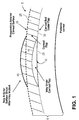
- FIG 1 shows an example of an intracorneal inlay 10 implanted in a cornea 5.
- the inlay 10 may have a meniscus shape with an anterior surface 15 and a posterior surface 20.
- the inlay 10 is preferably implanted in the cornea at a depth of 50% or less of the cornea (approximately 250 ⁇ m or less), and is placed on the stromal bed 30 of the cornea created by a micro keratome.
- the inlay 10 may be implanted in the cornea 5 by cutting a flap 25 into the cornea, lifting the flap 25 to expose the cornea's interior, placing the inlay 10 on the exposed area of the cornea's interior, and repositioning the flap 25 over the inlay 10.
- the flap 25 may be cut using a laser, e.g., a femtosecond laser, a mechanical keratome or manually by an ophthalmic surgeon.
- a laser e.g., a femtosecond laser, a mechanical keratome or manually by an ophthalmic surgeon.
- a small section of corneal tissue is left intact to create a hinge for the flap 25 so that the flap 25 can be repositioned accurately over the inlay 20.
- the cornea heals around the flap 25 and seals the flap 25 back to the un-cut peripheral portion of the anterior corneal surface.
- a pocket or well having side walls or barrier structures may be cut into the cornea, and the inlay inserted between the side walls or barrier structures through a small opening or "port" in the cornea.
- the inlay 10 changes the refractive power of the cornea by altering the shape of the anterior corneal surface.
- the pre-operative anterior corneal surface is represented by dashed line 35 and the post-operative anterior corneal surface induced by the underlying inlay 10 is represented by solid line 40.
- the inlay may have properties similar to those of the cornea (e.g., index of refraction around 1.376, water content of 78%, etc.), and may be made of hydrogel or other clear biocompatible material.
- the inlay may be made of a material with a higher index of refraction than the cornea, e.g., > 1.376.
- Materials that can be used for the inlay include, but are not limited to, Lidofilcon A, Poly-HEMA, poly sulfone, silicone hydrogel, and the like.
- the index of refraction maybe in the range of 1.33 to 1.55.
- a small inlay e.g., 1 to 2 mm in diameter
- effect zone is the area of the anterior corneal surface affected by the inlay.
- the implanted inlay increases the curvature of the anterior corneal surface within the "effect” zone, thereby increasing the diopter power of the cornea within the "effect” zone.
- Distance vision is provided by the region of the cornea peripheral to the "effect” zone.
- Presbyopia is characterized by a decrease in the ability of the eye to increase its power to focus on nearby objects due to a loss of elasticity in the crystalline lens with age.
- a person suffering from Presbyopia requires reading glasses to provide near vision.
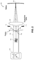
- Figure 2 shows an example of how a small inlay can provide near vision to a subject's eye while retaining some distance vision according to an embodiment of the invention.
- the eye 105 comprises the cornea 110, the pupil 115, the crystalline lens 120 and the retina 125.
- the small inlay (not shown) is implanted centrally in the cornea to create a small diameter "effect" zone 130.
- the small inlay has a smaller diameter than the pupil 115 so that the resulting "effect" zone 130 has a smaller diameter than the optical zone of the cornea.
- the "effect" zone 130 provides near vision by increasing the curvature of the anterior corneal surface, and therefore the diopter power within the "effect" zone 130.
- the region 135 of the cornea peripheral to the "effect" zone provides distance vision.
- the small inlay has a higher curvature than the pre-implant anterior corneal surface to increase the curvature of the anterior corneal surface within the "effect” zone 130.
- the increase in the diopter power within the "effect” zone 130 may be due to the change in the anterior corneal surface induced by the inlay or a combination of the change in the anterior cornea surface and the index of refraction of the inlay.
- At least 1 diopter is typically required for near vision.
- For complete presbyopes e.g., about 60 years of age or older, between 2 and 3 diopters of additional power is required.
- An advantage of the small intracorneal inlay is that when concentrating on nearby objects 140, the pupil naturally becomes smaller (e.g., near point miosis) making the inlay effect even more effective. Further increases in the inlay effect can be achieved by simply increasing the illumination of a nearby object (e.g., turning up a reading light).
- the inlay is smaller than the diameter of the pupil 115, light rays 150 from distant objects 145 by-pass the inlay and refract using the region of the cornea peripheral to the "effect" zone to create an image of the distant objects on the retina 125, as shown in Figure 2 . This is particularly true with larger pupils. At night, when distance vision is most important, the pupil naturally becomes larger, thereby reducing the inlay effect and maximizing distance vision.
- a subject's natural distance vision is in focus only if the subject is emmetropic (i.e., does not require glasses for distance vision). Many subjects are ammetropic, requiring either myopic or hyperopic refractive correction.
- distance vision correction can be provided by myopic Laser in Situ Keratomileusis (LASIK), Laser Epithelial Keratomileusis (LASEK), Photorefractive Keratectomy (PRK) or other similar corneal refractive procedures.
- LASIK Laser in Situ Keratomileusis
- LASEK Laser Epithelial Keratomileusis
- PRK Photorefractive Keratectomy
- the small inlay can be implanted in the cornea to provide near vision. Since LASIK requires the creation of a flap, the inlay may be inserted concurrently with the LASIK procedure. The inlay may also be inserted into the cornea after the LASIK procedure since the flap can be re-opened. Therefore, the small inlay may be used in conjunction with other refractive procedures, such as
- Figure 3 shows a small inlay 210 implanted in the cornea 205 and the change in the shape of the anterior corneal surface 240 induced by the inlay 210.
- the pre-implant anterior corneal surface is represented by dashed line 235 and the post-implant anterior corneal surface induced by the inlay 210 is represented by solid line 240.
- the inlay 210 does not substantially affect the shape of the anterior corneal surface in the region of the cornea 210 peripheral to the "effect" zone so that distance vision is undisturbed in the peripheral 245.
- the pre-implant anterior corneal surface 235 is the anterior corneal surface after the distance corrective procedure but before implantation of the inlay.
- the inlay 210 has a finite edge thickness 250.
- the edge thickness 250 can not be made zero due to the finite material properties of the inlay.
- the finite edge thickness 250 of the inlay produces a draping effect, as described further below.
- the edge thickness 250 of the inlay 210 can be made as small as possible, e.g., less than about 20 microns.
- the inlay may have a tapered region (not shown) that tapers downward from the anterior surface 215 of the inlay to the edge 250 of the inlay.
- the tapered region may be 10 - 30 ⁇ m in length.
- the portion of the anterior corneal surface directly above the inlay is altered by the physical shape of the inlay 210. Because of the finite edge thickness 250 of the inlay 210, the anterior corneal surface does not immediately return to its pre-implant shape for a diameter larger than the physical inlay 210. Eventually, the anterior corneal surface returns to the pre-implant corneal surface 235. Therefore, the draping effect produces a drape region 255 that extends the shape change of the anterior corneal surface induced by the inlay 210.
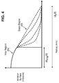
- Figure 4 illustrates a variety of possible draping shapes 355.
- Figure 4 shows the radius (d I /2) of an inlay region 362 and the total radius (d Z /2) of the shape change due to the draping effect.
- the possible draping shapes 355 are shown in dashed lines, and may depend on factors such as the edge thickness, the local mechanical properties of the flap material, the diameter of the inlay (dI), the mechanical properties of the inlay material, and other geometric factors.
- the precise shape of the drape can be approximated by invitro or invivo clinical experiments and/or by complex mechanical modeling using techniques such as finite element analysis.
- optical zone diameter corresponding to the size of the anterior corneal surface affected by the inlay 210, as shown in Figure 3 .
- the relationship between the optical zone and the inlay diameter can be determined by the methods outlined above.
- step three The design method of step three will now be given.
- Figures 3 and 4 show two regions affected by the inlay design: a "central region” 260 defined by the inlay diameter (dI), and a “drape region” 255 falling between the inlay diameter and the optical zone (dz).
- the design method described below is used to design inlays to produce desired shapes of the anterior corneal surface in the central region to correct presbyopia. This design method assumes that the inlay material has the same index of refraction as the cornea.
- a first step in the design of an inlay in the central region is determining a thickness profile that the inlay must induce on the anterior corneal surface to produce a desired anterior corneal curvature.
- the desired ADD power needed to provide near focus dictates the desired anterior corneal curvature in the central region ( Figure 4 ).
- Rxdist is approximately zero diopters for emmetropic individuals, or is equal to the achieved or targeted post-operative distance refraction after a surgical procedure to correct the distance ammetropia.
- V is a spectacle vertex distance, e.g., 0.012 meters, from a spectacle to the cornea's anterior surface.
- the spectacle vertex distance, V takes into account that measurements of the cornea's refractive power are typically taken with a spectacle located a distance from the cornea's anterior surface, and translates these power measurements to the equivalent power at cornea's anterior surface.
- the pre-implant refractive power at the anterior corneal surface may be approximated by Kavg - Kpost, where Kavg is the average corneal refractive power within approximately the optical zone created by the inlay and Kpost is a posterior corneal refractive power.
- the desired radius of curvature, r' a , of the anterior surface may be given by: r a ′ 1.376 ⁇ 1 Kavg ⁇ Kpost + ⁇ ⁇ equiv
- Kpost may be approximated as -6 diopters.
- the two radius of curvatures need not originate from the same origin.
- Figure 5 shows a cross-sectional view of a thickness profile 510 specified by a difference between the desired anterior corneal surface 540 and the pre-implant anterior corneal surface 535.
- arrows 550 pointing from the pre-implant anterior surface 535 to the desired anterior surface 540 represent the axial thickness, L(r), of the thickness profile 510 at different positions along an r axis that is substantially perpendicular to an optical z axis.
- the double arrow 560 represents a center thickness, L c , of the thickness profile.
- the thickness profile 510 is rotationally symmetric about the z axis.
- the entire thickness profile may be defined by rotating the cross-sectional view shown in Figure 5 about the z axis.
- L c is the center thickness of the thickness profile
- Z implant (r) is the pre-operative anterior corneal surface as a function of r
- Z anew (r) is the desired anterior corneal surface as a function of r
- dI is the diameter of the inlay.
- the anterior surfaces Z anew and Z preimplant were assumed to be spherical. This need not be the case.
- the anterior surfaces may also be aspheric.
- the desired anterior surface Z anew may be a function of desired ADD and also more complex design parameters, e.g., an aspheric surface for higher-order aberration correction.
- the pre-implant anterior surface Z preimplant is generally aspheric.
- the inlay is dimensioned to have substantially the same thickness profile.
- the profiles should have the same thickness to within about one micron, which would cause a diopter difference of about one eight of a diopter if the center thickness differs by one micron.
- An eight of a diopter is half the accuracy with which ophthalmic refractive errors are manually recorded.
- the thickness profile of the inlay is increased by the finite edge thickness (h edge ) by the manufacturing process. This finite edge thickness is one factor inducing the drape as illustrated in Figure 4 .
- the thickness profile of the inlay is substantially transferred to the anterior corneal surface through the intervening flap, thereby producing the desired post-implant anterior corneal surface in the central region.
- the draping effect causes the change in the anterior corneal surface thickness to extend beyond the central region. This draping effect can be minimized, e.g., by reducing the finite edge thickness of the inlay as much as possible.
- the design method above assumed that the index of refractive of the inlay is the same as the cornea, in which case changes in refractive power of the cornea is due solely to the change in the anterior corneal surface induced by the inlay.
- An inlay with intrinsic power e.g., a higher index of refraction than the cornea
- changes in the refractive power is provided by a combination of the physical inlay shape and the intrinsic power (i.e., index of refraction) of the inlay.
- an inlay it is desirable for an inlay to induce an effective optical zone on the anterior corneal surface that is much larger than the inlay diameter.
- the increase in the effective optical zone allows the inlay to produce a much larger clinical effect on the patient's vision than the actual inlay diameter.
- a 1.5 mm - 2 mm range diameter inlay has an increased effective optical zone of 4 mm - 5 mm, in which the optical effect of the inlay is 2x to 3x greater than its diameter.
- the increased effective optical zone can also be achieved with inlay diameters outside the above range. For example, the diameter of the inlay may go down to 1 mm or less for some designs, while achieving the desired optical effect.
- the increase in the effective optical zone (i.e., "effect" zone) of the inlay can be achieved by increasing the draping effect of the inlay.
- Increasing the draping effect extends the drape region, and therefore the effective optical zone (i.e., the area of the anterior corneal surface affected by the inlay).
- the draping effect may be increased, e.g., by increasing the finite edge thickness of the inlay so that the anterior corneal surface returns to its pre-implant surface at a larger radius.
- Small diameter inlays inducing effective optical zones much larger than the inlay diameter may be used to correct hyperopia.
- an inlay with a diameter of 2 mm can provide increased diopter power over an effective optical zone having a diameter of 4 mm.
- the curvature of the anterior corneal surface in the drape region is greater than the pre-implant anterior corneal surface. Therefore, the draping effect extends the area of the anterior corneal surface where the curvature is increased, thereby extending the effective optical zone of the inlay and providing increased diopter power over a wider diameter than the inlay diameter. This increase in the effective optical zone allows for the correction of hyperopia using smaller diameter inlays.
- An inlay with increased effective optical zone may also be used to correct various vision impairments including presbyopia, hyperopia, myopia, and higher order aberrations.
- a sufficient "effect" zone may be achieved with an even smaller diameter inlay.
- a 1 mm diameter inlay may be used to produce a 2 mm diameter "effect" zone.
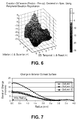
- FIG. 6 shows an example of a 3D topographic difference map showing the change in the anterior corneal surface for a subject (subject 1) between a preoperative examination and a one week postoperative examination.
- an intracorneal inlay was implanted in subject 1 having a diameter of 2 mm, a center thickness of approximately 36 microns, and an edge thickness of approximately 30 microns.
- the inlay was placed under a corneal flap created using a laser keratome (by Intralase, Inc.) at a depth of approximately 110 microns.
- a Scheimpflug topographer (“Pentacam” by Oculus, Inc.) was used to measure the surfaces. From Figure 6 , it is clear that the implanted inlay steepened the anterior corneal surface.
- Figure 7 shows the average radial elevation profile calculated from data in Figure 6 . Average radial profiles for two additional subjects (subjects 2 and 3) who received the same inlay design are also shown. Note that the central anterior surface elevation change was less than the center thickness of the inlay. This reflects biomechanical interactions between the inlay material, stromal bed on which it rests and the overlying keratometric flap. However, in all cases the inlay increased the anterior surface elevation beyond the physical diameter of the inlay. Figure 7 suggests that the effective optical zone induced by the inlay was approximately twice the inlay diameter for this particular design. Inlays with different diameters, center thicknesses and thickness profiles may have different "effect" zone sizes.
Abstract
Description
- The field of the invention relates generally to corneal implants, and more particularly, to intracorneal inlays.
- As is well known, abnormalities in the human eye can lead to vision impairment. Some typical abnormalities include variations in the shape of the eye, which can lead to myopia (near-sightedness), hyperopia (far-sightedness) and astigmatism as well as variations in the tissue present throughout the eye, such as a reduction in the elasticity of the lens, which can lead to presbyopia. A variety of technologies have been developed to try and address these abnormalities, including corneal implants.
- Corneal implants can correct vision impairment by altering the shape of the cornea. Corneal implants can be classified as an onlay or an inlay. An onlay is an implant that is placed over the cornea such that the outer layer of the cornea, e.g., the epithelium, can grow over and encompass the implant. An inlay is an implant that is surgically implanted into the cornea beneath a portion of the corneal tissue by, for example, cutting a flap in the cornea and inserting the inlay beneath the flap. Both inlays and outlays can alter the refractive power of the cornea by changing the shape of the anterior cornea, by having a different index of refraction than the cornea, or both. Since the cornea is the strongest refracting optical element in the human ocular system, altering the cornea's anterior surface is a particularly useful method for correcting vision impairments caused by refractive errors. Inlays are also useful for correcting other visual impairments including presbyopia.
- Provided herein are small diameter inlays for correcting vision impairments by altering the shape of the anterior corneal surface.
- In one embodiment, inlays having diameters smaller than the diameter of the pupil are provided for correcting presbyopia. To provide near vision, an inlay is implanted centrally in the corneal to induce an "effect" zone on the anterior corneal surface that is smaller than the optical zone of the cornea, wherein the "effect" zone is the area of the anterior corneal surface affected by the inlay. The implanted inlay increases the curvature of the anterior corneal surface within the "effect" zone, thereby increasing the diopter power of the cornea within the "effect" zone. Because the inlay is smaller than the diameter of the pupil, light rays from distance objects by-pass the inlay and refract using the region of the cornea peripheral to the "effect" zone to create an image of the distant objects on the retina.
- The small diameter inlays may be used alone or in conjunction with other refractive procedures. In an embodiment, a small diameter inlay is used in conjunction with LASIK for correcting myopia or hyperopia. In this embodiment, a LASIK procedure is used to correct for distance refractive error and the small diameter inlay is used to provide near vision for presbyopic subjects.
- In another embodiment, small diameter inlays are provided that induce effective optical zones on the anterior corneal surface that are much larger in diameter than the inlays. The increase in the effective optical zone allows an inlay to produce a much larger clinical effect on a patient's vision than the diameter of the inlay.
- In one embodiment, the effective optical zone induced by the inlay is increased by increasing the draping effect of the inlay. The draping effect extends the area of the anterior corneal surface affected by the inlay, and thereby the effective optical zone induced by the inlay. In an embodiment, the draping effect is increased by increasing the finite edge thickness of the inlay for a given inlay diameter and center thickness.
- In another embodiment, inlays having effective optical zones much larger than the inlay diameter are used to correct hyperopia. In this embodiment, the draping effect extends the area of the anterior corneal surface where the curvature is increased, thereby extending the effective optical zone of the inlay and providing increased diopter power over a wider diameter than the inlay diameter. This increase in the effective optical zone allows for the correction of hyperopia using smaller diameter inlays.
- Other systems, methods, features and advantages of the invention will be or will become apparent to one with skill in the art upon examination of the following figures and detailed description. It is intended that all such additional systems, methods, features and advantages be included within this description, be within the scope of the invention, and be protected by the accompanying claims. It is also intended that the invention not be limited to the details of the example embodiments.
-
-
Figure 1 is a cross-sectional view of a cornea showing an intracorneal inlay implanted in the cornea according to an embodiment of the invention. -
Figure 2 is a diagram of an eye illustrating the use of a small diameter inlay to provide near vision according to an embodiment of the invention. -
Figure 3 is a cross-sectional view of a cornea showing an inlay implanted in the cornea and a change in the anterior corneal surface induced by the inlay including a drape region according to an embodiment of the invention. -
Figure 4 illustrates various possible shapes for the drape region. -
Figure 5 is a cross-sectional view of a cornea showing a thickness profile for providing a desired refractive correction according to an embodiment of the invention. -
Figure 6 is a 3D topographic difference map showing the change in the anterior corneal surface induced by an inlay according to an embodiment of the invention. -
Figure 7 shows an average radial elevation profile induced by an inlay according to an embodiment of the invention. -
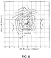
Figure 8 shows a contour map of the refractive change induced by an inlay according to an embodiment of the invention. -
Figure 1 shows an example of anintracorneal inlay 10 implanted in acornea 5. Theinlay 10 may have a meniscus shape with ananterior surface 15 and aposterior surface 20. Theinlay 10 is preferably implanted in the cornea at a depth of 50% or less of the cornea (approximately 250 µm or less), and is placed on thestromal bed 30 of the cornea created by a micro keratome. Theinlay 10 may be implanted in thecornea 5 by cutting aflap 25 into the cornea, lifting theflap 25 to expose the cornea's interior, placing theinlay 10 on the exposed area of the cornea's interior, and repositioning theflap 25 over theinlay 10. Theflap 25 may be cut using a laser, e.g., a femtosecond laser, a mechanical keratome or manually by an ophthalmic surgeon. When theflap 25 is cut into the cornea, a small section of corneal tissue is left intact to create a hinge for theflap 25 so that theflap 25 can be repositioned accurately over theinlay 20. After theflap 25 is repositioned over the inlay, the cornea heals around theflap 25 and seals theflap 25 back to the un-cut peripheral portion of the anterior corneal surface. Alternatively, a pocket or well having side walls or barrier structures may be cut into the cornea, and the inlay inserted between the side walls or barrier structures through a small opening or "port" in the cornea. - The
inlay 10 changes the refractive power of the cornea by altering the shape of the anterior corneal surface. InFigure 1 , the pre-operative anterior corneal surface is represented bydashed line 35 and the post-operative anterior corneal surface induced by theunderlying inlay 10 is represented bysolid line 40. - The inlay may have properties similar to those of the cornea (e.g., index of refraction around 1.376, water content of 78%, etc.), and may be made of hydrogel or other clear biocompatible material. To increase the optical power of the inlay, the inlay may be made of a material with a higher index of refraction than the cornea, e.g., > 1.376. Materials that can be used for the inlay include, but are not limited to, Lidofilcon A, Poly-HEMA, poly sulfone, silicone hydrogel, and the like. The index of refraction maybe in the range of 1.33 to 1.55.
- This section discusses the use of small intracorneal inlays having diameters that are small in comparison with the pupil for correcting presbyopia. In the preferred embodiment, a small inlay (e.g., 1 to 2 mm in diameter) is implanted centrally in the cornea to induce an "effect" zone on the anterior corneal surface that is smaller than the optical zone of the cornea for providing near vision. Here, "effect" zone is the area of the anterior corneal surface affected by the inlay. The implanted inlay increases the curvature of the anterior corneal surface within the "effect" zone, thereby increasing the diopter power of the cornea within the "effect" zone. Distance vision is provided by the region of the cornea peripheral to the "effect" zone.
- Presbyopia is characterized by a decrease in the ability of the eye to increase its power to focus on nearby objects due to a loss of elasticity in the crystalline lens with age. Typically, a person suffering from Presbyopia requires reading glasses to provide near vision.
-
Figure 2 shows an example of how a small inlay can provide near vision to a subject's eye while retaining some distance vision according to an embodiment of the invention. Theeye 105 comprises thecornea 110, thepupil 115, thecrystalline lens 120 and theretina 125. In this example, the small inlay (not shown) is implanted centrally in the cornea to create a small diameter "effect"zone 130. The small inlay has a smaller diameter than thepupil 115 so that the resulting "effect"zone 130 has a smaller diameter than the optical zone of the cornea. The "effect"zone 130 provides near vision by increasing the curvature of the anterior corneal surface, and therefore the diopter power within the "effect"zone 130. Theregion 135 of the cornea peripheral to the "effect" zone provides distance vision. - To increase the diopter power within the "effect"
zone 130, the small inlay has a higher curvature than the pre-implant anterior corneal surface to increase the curvature of the anterior corneal surface within the "effect"zone 130. The inlay may further increase the diopter power within the "effect"zone 130 by having an index of refraction that is higher than the index of refraction of the cornea (ncornea = 1.376). Thus, the increase in the diopter power within the "effect"zone 130 may be due to the change in the anterior corneal surface induced by the inlay or a combination of the change in the anterior cornea surface and the index of refraction of the inlay. For early presbyopes (e.g., about 45 to 55 years of age), at least 1 diopter is typically required for near vision. For complete presbyopes (e.g., about 60 years of age or older), between 2 and 3 diopters of additional power is required. - An advantage of the small intracorneal inlay is that when concentrating on
nearby objects 140, the pupil naturally becomes smaller (e.g., near point miosis) making the inlay effect even more effective. Further increases in the inlay effect can be achieved by simply increasing the illumination of a nearby object (e.g., turning up a reading light). - Because the inlay is smaller than the diameter of the
pupil 115,light rays 150 fromdistant objects 145 by-pass the inlay and refract using the region of the cornea peripheral to the "effect" zone to create an image of the distant objects on theretina 125, as shown inFigure 2 . This is particularly true with larger pupils. At night, when distance vision is most important, the pupil naturally becomes larger, thereby reducing the inlay effect and maximizing distance vision. - A subject's natural distance vision is in focus only if the subject is emmetropic (i.e., does not require glasses for distance vision). Many subjects are ammetropic, requiring either myopic or hyperopic refractive correction. Especially for myopes, distance vision correction can be provided by myopic Laser in Situ Keratomileusis (LASIK), Laser Epithelial Keratomileusis (LASEK), Photorefractive Keratectomy (PRK) or other similar corneal refractive procedures. After the distance corrective procedure is completed, the small inlay can be implanted in the cornea to provide near vision. Since LASIK requires the creation of a flap, the inlay may be inserted concurrently with the LASIK procedure. The inlay may also be inserted into the cornea after the LASIK procedure since the flap can be re-opened. Therefore, the small inlay may be used in conjunction with other refractive procedures, such as LASIK for correcting myopia or hyperopia.
- A method for designing a small inlay to provide near vision will now be described.
Figure 3 shows asmall inlay 210 implanted in thecornea 205 and the change in the shape of the anteriorcorneal surface 240 induced by theinlay 210. InFigure 3 , the pre-implant anterior corneal surface is represented by dashedline 235 and the post-implant anterior corneal surface induced by theinlay 210 is represented bysolid line 240. Theinlay 210 does not substantially affect the shape of the anterior corneal surface in the region of thecornea 210 peripheral to the "effect" zone so that distance vision is undisturbed in the peripheral 245. In the case where a distance corrective procedure is performed prior to implantation of the inlay, the pre-implant anteriorcorneal surface 235 is the anterior corneal surface after the distance corrective procedure but before implantation of the inlay. - The
inlay 210 has afinite edge thickness 250. Theedge thickness 250 can not be made zero due to the finite material properties of the inlay. Thefinite edge thickness 250 of the inlay produces a draping effect, as described further below. To minimize the draping effect, theedge thickness 250 of theinlay 210 can be made as small as possible, e.g., less than about 20 microns. In addition to afinite edge thickness 250, the inlay may have a tapered region (not shown) that tapers downward from theanterior surface 215 of the inlay to theedge 250 of the inlay. The tapered region may be 10 - 30 µm in length. - In
Figure 3 , the portion of the anterior corneal surface directly above the inlay is altered by the physical shape of theinlay 210. Because of thefinite edge thickness 250 of theinlay 210, the anterior corneal surface does not immediately return to its pre-implant shape for a diameter larger than thephysical inlay 210. Eventually, the anterior corneal surface returns to the pre-implantcorneal surface 235. Therefore, the draping effect produces adrape region 255 that extends the shape change of the anterior corneal surface induced by theinlay 210. -
Figure 4 illustrates a variety of possible draping shapes 355.Figure 4 shows the radius (dI/2) of aninlay region 362 and the total radius (dZ/2) of the shape change due to the draping effect. The possible draping shapes 355 are shown in dashed lines, and may depend on factors such as the edge thickness, the local mechanical properties of the flap material, the diameter of the inlay (dI), the mechanical properties of the inlay material, and other geometric factors. The precise shape of the drape can be approximated by invitro or invivo clinical experiments and/or by complex mechanical modeling using techniques such as finite element analysis. - It is useful to define the optical zone diameter (dz) corresponding to the size of the anterior corneal surface affected by the
inlay 210, as shown inFigure 3 . For purposes of the design method, it is sufficient to assume that the relationship between the optical zone and the inlay diameter, given the other variables, can be determined by the methods outlined above. - A method for designing a small inlay to provide near vision according to an embodiment will now be given.
- (1) The first step is to determine the maximum optical zone (dz) that is an acceptable tradeoff between the near vision improvement and the loss of distance vision. Considerations include the pupil size of the specific subject or a group of characteristic subjects (e.g., subjects within a particular age range) while reading nearby objects and the pupil size for distance viewing, especially at night. In an exemplary application, the inlay is placed in one eye to provide near vision and distance correction by other means is performed on the fellow eye. In this example, both eyes contribute to distance vision, with the non-inlay eye providing the sharpest distance vision. The eye with the inlay provides near vision.
- (2) Given the empirically derived or theoretically derived relationship between the optical zone (dz) and the inlay diameter (dI), approximate the inlay diameter that achieves the optical zone.
- (3) Design the inlay using the method outlined in detail below. This methods is similar to the design methods described in
U.S. Patent Application Serial No. 11/293,644 - (4) Finally, use optical ray-trace methods to assess the image quality of distance and near images with the inlay using the entire corneal surface (i.e., the corneal surface within the inlay diameter (dI), between the inlay diameter and the optical zone (dz), and the peripheral to the optical zone). Make small adjustments to the inlay design to optimize the distance and near image quality based on the inlay design method outlined below and the predicted drape shape given by the methods described above.
- The design method of step three will now be given.
-
Figures 3 and4 show two regions affected by the inlay design: a "central region" 260 defined by the inlay diameter (dI), and a "drape region" 255 falling between the inlay diameter and the optical zone (dz). The design method described below is used to design inlays to produce desired shapes of the anterior corneal surface in the central region to correct presbyopia. This design method assumes that the inlay material has the same index of refraction as the cornea. - A first step in the design of an inlay in the central region is determining a thickness profile that the inlay must induce on the anterior corneal surface to produce a desired anterior corneal curvature. The desired ADD power needed to provide near focus dictates the desired anterior corneal curvature in the central region (
Figure 4 ). - A first step in determining the thickness profile of the inlay is to determine an anterior radius of curvature, r'a, that provides the desired refractive change, ΔRx = Rxdist - ADD, where ADD is the desired ADD power prescribed for near vision and Rxdist is the distance refraction prior to inlay implant. Rxdist is approximately zero diopters for emmetropic individuals, or is equal to the achieved or targeted post-operative distance refraction after a surgical procedure to correct the distance ammetropia. The equivalent change in the cornea's refractive power, ΔKequiv, at the anterior surface is given by:

- The pre-implant refractive power at the anterior corneal surface may be approximated by Kavg - Kpost, where Kavg is the average corneal refractive power within approximately the optical zone created by the inlay and Kpost is a posterior corneal refractive power. The desired radius of curvature, r'a, of the anterior surface may be given by:


-
Figure 5 shows a cross-sectional view of athickness profile 510 specified by a difference between the desired anteriorcorneal surface 540 and the pre-implant anterior corneal surface 535. InFigure 5 , arrows 550 pointing from the pre-implant anterior surface 535 to the desiredanterior surface 540 represent the axial thickness, L(r), of thethickness profile 510 at different positions along an r axis that is substantially perpendicular to an optical z axis. Thedouble arrow 560 represents a center thickness, Lc, of the thickness profile. In this embodiment, thethickness profile 510 is rotationally symmetric about the z axis. Thus, the entire thickness profile may be defined by rotating the cross-sectional view shown inFigure 5 about the z axis. - The thickness L(r) of the thickness profile may be given by:


- rc is the radius of curvature
- k is a conic constant
- a4 and a6 are higher order aspheric constants
- The above expressions for the thickness profile are intended to be exemplary only. Other mathematical expressions or parameters may be used to describe similar or other thickness profiles. Therefore, the invention is not limited to particular mathematical expressions or parameters for describing the thickness profile.
- After the required thickness profile L(r) is determined, the inlay is dimensioned to have substantially the same thickness profile. The profiles should have the same thickness to within about one micron, which would cause a diopter difference of about one eight of a diopter if the center thickness differs by one micron. An eight of a diopter is half the accuracy with which ophthalmic refractive errors are manually recorded. Next, the thickness profile of the inlay is increased by the finite edge thickness (hedge) by the manufacturing process. This finite edge thickness is one factor inducing the drape as illustrated in
Figure 4 . When implanted in the cornea, the thickness profile of the inlay is substantially transferred to the anterior corneal surface through the intervening flap, thereby producing the desired post-implant anterior corneal surface in the central region. The draping effect causes the change in the anterior corneal surface thickness to extend beyond the central region. This draping effect can be minimized, e.g., by reducing the finite edge thickness of the inlay as much as possible. - The design method above assumed that the index of refractive of the inlay is the same as the cornea, in which case changes in refractive power of the cornea is due solely to the change in the anterior corneal surface induced by the inlay. An inlay with intrinsic power (e.g., a higher index of refraction than the cornea) may also be used, in which changes in the refractive power is provided by a combination of the physical inlay shape and the intrinsic power (i.e., index of refraction) of the inlay. Design methods for inlays with intrinsic power is described in Application Serial No.
11/381,056 - For some applications, it is desirable for an inlay to induce an effective optical zone on the anterior corneal surface that is much larger than the inlay diameter. The increase in the effective optical zone allows the inlay to produce a much larger clinical effect on the patient's vision than the actual inlay diameter. In one example, a 1.5 mm - 2 mm range diameter inlay has an increased effective optical zone of 4 mm - 5 mm, in which the optical effect of the inlay is 2x to 3x greater than its diameter. The increased effective optical zone can also be achieved with inlay diameters outside the above range. For example, the diameter of the inlay may go down to 1 mm or less for some designs, while achieving the desired optical effect.
- The increase in the effective optical zone (i.e., "effect" zone) of the inlay can be achieved by increasing the draping effect of the inlay. Increasing the draping effect extends the drape region, and therefore the effective optical zone (i.e., the area of the anterior corneal surface affected by the inlay). The draping effect may be increased, e.g., by increasing the finite edge thickness of the inlay so that the anterior corneal surface returns to its pre-implant surface at a larger radius.
- Small diameter inlays inducing effective optical zones much larger than the inlay diameter may be used to correct hyperopia. For example, an inlay with a diameter of 2 mm can provide increased diopter power over an effective optical zone having a diameter of 4 mm. The curvature of the anterior corneal surface in the drape region is greater than the pre-implant anterior corneal surface. Therefore, the draping effect extends the area of the anterior corneal surface where the curvature is increased, thereby extending the effective optical zone of the inlay and providing increased diopter power over a wider diameter than the inlay diameter. This increase in the effective optical zone allows for the correction of hyperopia using smaller diameter inlays.
- An inlay with increased effective optical zone may also be used to correct various vision impairments including presbyopia, hyperopia, myopia, and higher order aberrations. In the case of presbyopia, a sufficient "effect" zone may be achieved with an even smaller diameter inlay. For example, a 1 mm diameter inlay may be used to produce a 2 mm diameter "effect" zone.
- Clinical data will now be presented in which the effective optical zone induced by an inlay is larger than the inlay diameter. In general, topographic instruments can be used to measure the change in the anterior surface elevation induced by an inlay, calculate the change in the anterior surface curvature and deduce the change in the diopter power.
Figure 6 shows an example of a 3D topographic difference map showing the change in the anterior corneal surface for a subject (subject 1) between a preoperative examination and a one week postoperative examination. In this example, an intracorneal inlay was implanted insubject 1 having a diameter of 2 mm, a center thickness of approximately 36 microns, and an edge thickness of approximately 30 microns. The inlay was placed under a corneal flap created using a laser keratome (by Intralase, Inc.) at a depth of approximately 110 microns. A Scheimpflug topographer ("Pentacam" by Oculus, Inc.) was used to measure the surfaces. FromFigure 6 , it is clear that the implanted inlay steepened the anterior corneal surface. -
Figure 7 shows the average radial elevation profile calculated from data inFigure 6 . Average radial profiles for two additional subjects (subjects 2 and 3) who received the same inlay design are also shown. Note that the central anterior surface elevation change was less than the center thickness of the inlay. This reflects biomechanical interactions between the inlay material, stromal bed on which it rests and the overlying keratometric flap. However, in all cases the inlay increased the anterior surface elevation beyond the physical diameter of the inlay.Figure 7 suggests that the effective optical zone induced by the inlay was approximately twice the inlay diameter for this particular design. Inlays with different diameters, center thicknesses and thickness profiles may have different "effect" zone sizes. -
Figure 8 shows a contour map of the refractive change induced by the intracorneal inlay. This is calculated from the elevation differences by calculating the saggital curvature map and converting to diopter power using:
- In the foregoing specification, the invention has been described with reference to specific embodiments thereof. It will, however, be evident that various modifications and changes may be made thereto without departing from the broader spirit and scope of the invention. As another example, each feature of one embodiment can be mixed and matched with other features shown in other embodiments. As yet another example, the order of steps of method embodiments may be changed. Features and processes known to those of ordinary skill may similarly be incorporated as desired. Additionally and obviously, features may be added or subtracted as desired. Accordingly, the invention is not to be restricted except in light of the attached claims and their equivalents.
- The claims of the parent application are reproduced below on pages 13 to 15. These clauses define preferred embodiments. The applicant reserves the right to pursue protection for the combinations of features set out in these clauses, and/or for any other subject-matter contained in the parent application as filed, either in the present divisional application or in a further application divided from the present divisional application. The claims of the parent application are not the claims of this divisional application.
-
- 1. A method for treating presbyopia using an intracorneal inlay, comprising:
- altering the shape of the anterior surface of a cornea to correct near vision by implanting the inlay in the cornea, wherein the inlay has a diameter of approximately 2.5 mm or less, and distance vision is provided by a region of the cornea peripheral to an area of the anterior surface affected by the inlay.
- 2. The method of
clause 1, wherein the inlay has an index of refraction substantially equal to the index of refraction of the cornea. - 3. The method of
clause 1, wherein the inlay has an index of refraction higher than the index of refraction of the cornea. - 4. The method of
clause 1, wherein the inlay is implanted at a depth of 50% or less of the cornea. - 5. The method of
clause 1, wherein the inlay is implanted at a depth of 25% or less of the cornea. - 6. The method of
clause 1, wherein a curvature of an anterior surface of the inlay is higher than the curvature of the anterior surface of the cornea. - 7. The method of
clause 1, further comprising:- prior to implantation of the inlay, performing a corrective procedure on the cornea to correct distance vision.
- 8. The method of clause 7, wherein the corrective procedure to correct distance vision comprises a LASIK procedure.
- 9. The method of clause 8, further comprising:
- cutting a flap in the cornea during the LASIK procedure; and
- after the LASIK procedure, reopening the flap and implanting the inlay beneath the flap.
- 10. The method of
clause 1, further comprising performing a corrective procedure to correct distance vision concurrently with implantation of the inlay. - 11. The method of
clause 10, wherein the corrective procedure to correct distance vision comprises a LASIK procedure. - 12. The method of clause 11, further comprising:
- cutting a flap in the cornea during the LASIK procedure; and
- implanting the inlay beneath the flap.
- 13. The method of
clause 1, wherein the inlay has a diameter of approximately 2 mm or less. - 14. The method of
clause 1, wherein the inlay has a diameter of approximately 1.5 mm or less. - 15. The method of
clause 1, further comprising:- cutting a flap in the cornea;
- lifting the flap to expose an interior of the cornea;
- placing the inlay in the interior of the cornea; and
- repositioning the flap over the inlay.
- 16. The method of
clause 1, further comprising:- cutting a pocket in an interior of the cornea; and
- placing the inlay in the pocket.
- 17. A method for correcting visional impairment, comprising:
- implanting an inlay having a diameter in a cornea, wherein the inlay produces an effective optical zone on the anterior surface of the cornea having a diameter greater than the diameter of the inlay.
- 18. The method of clause 17, wherein the diameter of the effective optical zone is at least 1.5 times greater than the diameter of the inlay.
- 19. The method of clause 17, wherein the diameter of the effective optical zone is at least two times greater than the diameter of the inlay.
- 20. The method of clause 17, wherein the inlay increases the curvature of the anterior surface of the cornea, and an area of increased curvature has a diameter greater than the diameter of the inlay.
- 21. The method of
clause 20, wherein the area of increased curvature has a diameter at least 1.5 times greater than the diameter of the inlay. - 22. The method of
clause 20, wherein the area of increased curvature has a diameter at least 2 times greater than the diameter of the inlay. - 23. The method of clause 17, wherein the diameter of the inlay is less than 4 mm.
- 24. The method of clause 17, wherein the diameter of the inlay is less than 3 mm.
- 25. The method of clause 17, wherein the diameter of the inlay is in the range of 1.5 mm to 2 mm.
- 26. The method of clause 17, wherein the diameter of the inlay is less than 1.5 mm.
- 27. The method of clause 17, wherein the diameter of the inlay is less than 4 mm and the effective optical zone is 8 mm or less.
- 28. The method of clause 17, wherein the diameter of the inlay is less than 3 mm and the effective optical zone is in the range of about 6 mm to 8 mm.
- 29. The method of clause 17, wherein the diameter of the inlay in the range of 1.5 mm to 2 mm and the effective optical zone is in the range of about 4 mm to 5 mm.
- 30. The method of clause 17, wherein the diameter of the inlay is less than 1.5 mm and the effective optical zone is in the range of about 2 mm to 4 mm.
- 31. The method of clause 17, wherein the diameter of the inlay is less than 1 mm.
- 32. The method of clause 17, wherein the diameter of the inlay is less than 1 mm and the effective optical zone is in the range of about 2 mm to 4 mm.
- 33. The method of clause 17, wherein the center thickness of the inlay is less than 50 µm.
- 34. The method of clause 17, wherein the inlay is implanted in the cornea at a depth of 250 µm.
- 35. The method of clause 17, wherein the inlay is implanted in the cornea at a depth of 170 µm.
- 36. The method of clause 17, wherein the refractive index of the inlay is in the range of about 1.33 to 1.55.
Claims (7)
- An intracorneal inlay (10,210) for implantation into a cornea to treat presbyopia by altering the shape of the anterior surface of the cornea to correct near vision, wherein the inlay has a meniscus shape, a diameter of less than 3 mm, a spherical anterior surface (15, 215), and an index of refraction substantially equal to 1.376, and is constructed and arranged so that, when implanted, it will cause distance vision to be provided by a region of the cornea peripheral to an area of the anterior surface affected by the implanted inlay.
- The intracorneal inlay of claim 1, further comprising an edge (250) with a thickness of less than 20 µm.
- The intracorneal inlay of claim 1, further comprising a center thickness of less than 50 µm.
- The inlay of claim 1, wherein the inlay (10,210) has a diameter of approximately 2.5 mm or less.
- The inlay of claim 1, wherein the inlay (10,210) has a diameter of approximately 2.0 mm or less.
- The inlay of claim 1, wherein the inlay (10,210) has a diameter of approximately 1.5 mm or less.
- The inlay of claim 1, wherein the diameter of the inlay (10, 210) is in the range of 1.5 mm to 2 mm.
Applications Claiming Priority (3)
| Application Number | Priority Date | Filing Date | Title |
|---|---|---|---|
| US77645806P | 2006-02-24 | 2006-02-24 | |
| US11/554,544 US8057541B2 (en) | 2006-02-24 | 2006-10-30 | Method of using small diameter intracorneal inlays to treat visual impairment |
| EP07757220.4A EP1989585B1 (en) | 2006-02-24 | 2007-02-20 | Small diameter inlays |
Related Parent Applications (2)
| Application Number | Title | Priority Date | Filing Date |
|---|---|---|---|
| EP07757220.4A Division EP1989585B1 (en) | 2006-02-24 | 2007-02-20 | Small diameter inlays |
| EP07757220.4A Division-Into EP1989585B1 (en) | 2006-02-24 | 2007-02-20 | Small diameter inlays |
Publications (1)
| Publication Number | Publication Date |
|---|---|
| EP3125020A1 true EP3125020A1 (en) | 2017-02-01 |
Family
ID=38459717
Family Applications (2)
| Application Number | Title | Priority Date | Filing Date |
|---|---|---|---|
| EP16177295.9A Withdrawn EP3125020A1 (en) | 2006-02-24 | 2007-02-20 | Small diameter inlays |
| EP07757220.4A Not-in-force EP1989585B1 (en) | 2006-02-24 | 2007-02-20 | Small diameter inlays |
Family Applications After (1)
| Application Number | Title | Priority Date | Filing Date |
|---|---|---|---|
| EP07757220.4A Not-in-force EP1989585B1 (en) | 2006-02-24 | 2007-02-20 | Small diameter inlays |
Country Status (7)
| Country | Link |
|---|---|
| US (1) | US8057541B2 (en) |
| EP (2) | EP3125020A1 (en) |
| JP (2) | JP2009527340A (en) |
| AU (1) | AU2007220915B2 (en) |
| CA (2) | CA2643286C (en) |
| ES (1) | ES2593784T3 (en) |
| WO (1) | WO2007101016A2 (en) |
Families Citing this family (22)
| Publication number | Priority date | Publication date | Assignee | Title |
|---|---|---|---|---|
| JP2004526467A (en) | 2000-09-12 | 2004-09-02 | アナメッド インク. | Systems and methods for packaging and handling implants |
| US8668735B2 (en) | 2000-09-12 | 2014-03-11 | Revision Optics, Inc. | Corneal implant storage and delivery devices |
| US20110218623A1 (en) * | 2004-04-30 | 2011-09-08 | Jon Dishler | Small Diameter Inlays |
| US8057541B2 (en) | 2006-02-24 | 2011-11-15 | Revision Optics, Inc. | Method of using small diameter intracorneal inlays to treat visual impairment |
| US7776086B2 (en) | 2004-04-30 | 2010-08-17 | Revision Optics, Inc. | Aspherical corneal implant |
| US10835371B2 (en) | 2004-04-30 | 2020-11-17 | Rvo 2.0, Inc. | Small diameter corneal inlay methods |
| US20080262610A1 (en) * | 2007-04-20 | 2008-10-23 | Alan Lang | Biomechanical design of intracorneal inlays |
| US10555805B2 (en) | 2006-02-24 | 2020-02-11 | Rvo 2.0, Inc. | Anterior corneal shapes and methods of providing the shapes |
| CN101460114B (en) * | 2006-05-23 | 2011-07-06 | 阿尔贝特·达克瑟尔 | Corneal implant for correction of impaired vision in the human eye |
| US8162953B2 (en) | 2007-03-28 | 2012-04-24 | Revision Optics, Inc. | Insertion system for corneal implants |
| US9549848B2 (en) | 2007-03-28 | 2017-01-24 | Revision Optics, Inc. | Corneal implant inserters and methods of use |
| US9271828B2 (en) | 2007-03-28 | 2016-03-01 | Revision Optics, Inc. | Corneal implant retaining devices and methods of use |
| EP2265217A4 (en) | 2008-04-04 | 2018-04-04 | Revision Optics, Inc. | Corneal inlay design and methods of correcting vision |
| US9539143B2 (en) | 2008-04-04 | 2017-01-10 | Revision Optics, Inc. | Methods of correcting vision |
| US8469948B2 (en) | 2010-08-23 | 2013-06-25 | Revision Optics, Inc. | Methods and devices for forming corneal channels |
| JP5944005B2 (en) | 2011-10-21 | 2016-07-05 | リヴィジョン・オプティックス・インコーポレーテッド | Corneal graft storage and delivery device |
| EP2664300B1 (en) * | 2012-05-14 | 2020-10-28 | Presbia Ireland Limited | Intracorneal lens |
| US10092393B2 (en) | 2013-03-14 | 2018-10-09 | Allotex, Inc. | Corneal implant systems and methods |
| WO2016144404A1 (en) | 2015-03-12 | 2016-09-15 | Revision Optics, Inc. | Methods of correcting vision |
| US10449090B2 (en) | 2015-07-31 | 2019-10-22 | Allotex, Inc. | Corneal implant systems and methods |
| MX2018016173A (en) | 2016-06-23 | 2019-03-28 | Medicem Inst S R O | Light-adjustable hydrogel and bioanalogic intraocular lens. |
| US11690706B2 (en) | 2017-12-13 | 2023-07-04 | Allotex, Inc. | Corneal implant systems and methods |
Citations (9)
| Publication number | Priority date | Publication date | Assignee | Title |
|---|---|---|---|---|
| US5196026A (en) * | 1991-09-16 | 1993-03-23 | Chiron Ophthalmics, Inc. | Method of implanting corneal inlay lenses smaller than the optic zone |
| US5964748A (en) * | 1995-10-20 | 1999-10-12 | Peyman; Gholam A. | Intrastromal corneal modification |
| WO2001015779A1 (en) * | 1999-08-27 | 2001-03-08 | Anamed, Inc. | Corneal implant and method of manufacture |
| WO2003041616A1 (en) * | 2001-11-09 | 2003-05-22 | Peyman Gholam A | Method and apparatus for alignment of intracorneal inlay |
| WO2005082265A1 (en) * | 2004-02-24 | 2005-09-09 | Minu Llc | Method of treatment of refractive errors using subepithelial or intrastromal corneal inlay with bonding coating |
| US20050222679A1 (en) * | 2001-04-27 | 2005-10-06 | Peyman Gholam A | Bifocal implant and method for altering the refractive properties of the eye |
| WO2005107648A2 (en) * | 2004-04-30 | 2005-11-17 | Intralens Vision, Inc. | Aspherical corneal implant |
| US20060020267A1 (en) * | 2004-07-15 | 2006-01-26 | Marmo J C | Intrastromal devices and methods for improving vision |
| US20060077607A1 (en) | 2004-09-10 | 2006-04-13 | Henricks Michael C | Circuit protector monitoring assembly kit and method |
Family Cites Families (316)
| Publication number | Priority date | Publication date | Assignee | Title |
|---|---|---|---|---|
| US2714721A (en) | 1953-01-23 | 1955-08-09 | Jr William Stone | Artificial corneal implants |
| US3168100A (en) | 1962-12-07 | 1965-02-02 | Alvido R Rich | Contact lens dipper assembly |
| US3482906A (en) | 1965-10-04 | 1969-12-09 | David Volk | Aspheric corneal contact lens series |
| US3379200A (en) | 1965-10-24 | 1968-04-23 | Ruth M. Pennell | Lens containtr |
| US3343657A (en) | 1966-09-02 | 1967-09-26 | Reuben F Speshyock | Contact lens conditioning facility |
| US3950315A (en) | 1971-06-11 | 1976-04-13 | E. I. Du Pont De Nemours And Company | Contact lens having an optimum combination of properties |
| US3743337A (en) | 1971-07-26 | 1973-07-03 | E Crary | Contact lens inserter |
| US3770113A (en) | 1972-03-03 | 1973-11-06 | Mcd Corp | Contact lens holder |
| US3879076A (en) | 1973-12-27 | 1975-04-22 | Robert O Barnett | Method and apparatus for applying and removing a soft contact lens |
| US4065816A (en) | 1975-05-22 | 1978-01-03 | Philip Nicholas Sawyer | Surgical method of using a sterile packaged prosthesis |
| US3996627A (en) | 1975-09-22 | 1976-12-14 | American Optical Corporation | Artificial intraocular lens |
| US4037604A (en) | 1976-01-05 | 1977-07-26 | Newkirk John B | Artifical biological drainage device |
| US4030480A (en) | 1976-05-13 | 1977-06-21 | Ernst Jochen Meyer | Ocular decompression process |
| US4039827A (en) | 1976-08-26 | 1977-08-02 | American Optical Corporation | Method for marking intraocular lenses |
| US4071272A (en) | 1976-09-27 | 1978-01-31 | Drdlik Frank J | Contact lens applicator |
| US4136406A (en) | 1977-07-20 | 1979-01-30 | Norris John W | Intraocular lens with attached disposable instrument |
| US4157718A (en) | 1977-08-31 | 1979-06-12 | The United States Of America As Represented By The Administrator Of The National Aeronautics And Space Administration | Intra-ocular pressure normalization technique and equipment |
| US4184491A (en) | 1977-08-31 | 1980-01-22 | The United States Of America As Represented By The Administrator Of The National Aeronautics And Space Administration | Intra-ocular pressure normalization technique and equipment |
| US4194814A (en) | 1977-11-10 | 1980-03-25 | Bausch & Lomb Incorporated | Transparent opthalmic lens having engraved surface indicia |
| US4238524A (en) | 1978-03-06 | 1980-12-09 | American Optical Corporation | Process for identification marking clear plastic articles |
| US4268133A (en) | 1978-07-14 | 1981-05-19 | Bausch & Lomb Incorporated | Preferential orientation of contact lenses |
| US4392569A (en) | 1979-06-06 | 1983-07-12 | Shoup Leo E | Soft contact lens asepticizing case |
| US4418991A (en) | 1979-09-24 | 1983-12-06 | Breger Joseph L | Presbyopic contact lens |
| US4257521A (en) | 1979-11-16 | 1981-03-24 | Stanley Poler | Packaging means for an intraocular lens |
| US4709697A (en) | 1980-12-09 | 1987-12-01 | Joseph J. Berke | Tissue pneumatic separator structure and method |
| US4357940A (en) | 1979-12-13 | 1982-11-09 | Detroit Neurosurgical Foundation | Tissue pneumatic separator structure |
| US5022414A (en) | 1979-12-13 | 1991-06-11 | Joseph J. Berke | Tissue separator method |
| DE3169818D1 (en) | 1980-08-05 | 1985-05-15 | Choyce David P | Intraocular lens |
| US4326306A (en) | 1980-12-16 | 1982-04-27 | Lynell Medical Technology, Inc. | Intraocular lens and manipulating tool therefor |
| US4428746A (en) | 1981-07-29 | 1984-01-31 | Antonio Mendez | Glaucoma treatment device |
| US5188125A (en) | 1982-01-04 | 1993-02-23 | Keravision, Inc. | Method for corneal curvature adjustment |
| US4671276A (en) | 1982-01-04 | 1987-06-09 | Kera Associates | Apparatus for corneal curvature adjustment |
| US4766895A (en) | 1982-01-04 | 1988-08-30 | Kera Corneal Devices, Inc. | Apparatus for corneal curvature adjustment |
| US4452235A (en) | 1982-01-04 | 1984-06-05 | Reynolds Alvin E | Method for corneal curvature adjustment |
| US4490860A (en) | 1982-01-18 | 1985-01-01 | Ioptex Inc. | Intraocular lens apparatus and method for implantation of same |
| US4702244A (en) | 1982-02-05 | 1987-10-27 | Staar Surgical Company | Surgical device for implantation of a deformable intraocular lens |
| US4423809A (en) | 1982-02-05 | 1984-01-03 | Staar Surgical Company, Inc. | Packaging system for intraocular lens structures |
| DE3208729A1 (en) | 1982-03-11 | 1983-09-22 | Jörg Dr.med. 4630 Bochum Krumeich | Plastic lens |
| US4545478A (en) | 1982-07-08 | 1985-10-08 | Fred Waldman | Hard contact lens suction cups and method for their production |
| US4554918A (en) | 1982-07-28 | 1985-11-26 | White Thomas C | Ocular pressure relief device |
| US4504982A (en) | 1982-08-05 | 1985-03-19 | Optical Radiation Corporation | Aspheric intraocular lens |
| US4619256A (en) | 1982-09-08 | 1986-10-28 | Gerald Horn | Intraocular lens inserting assembly |
| US4466705A (en) | 1982-09-30 | 1984-08-21 | Michelson Paul E | Fluid lens |
| US4521210A (en) | 1982-12-27 | 1985-06-04 | Wong Vernon G | Eye implant for relieving glaucoma, and device and method for use therewith |
| US4616910A (en) | 1983-03-01 | 1986-10-14 | Klein Robert E | Visual indicator on soft contact lenses |
| US4580882A (en) | 1983-04-21 | 1986-04-08 | Benjamin Nuchman | Continuously variable contact lens |
| US4525044A (en) | 1983-05-05 | 1985-06-25 | Bauman Robert C | Soft contact lens with surface identification and method of using same |
| US4554115A (en) | 1983-08-30 | 1985-11-19 | Neefe Charles W | Method of controlling the convex curve of soft lenses |
| US4618227A (en) | 1983-10-07 | 1986-10-21 | Vistakon, Inc. | Soft contact lens |
| US4565198A (en) | 1983-12-27 | 1986-01-21 | Barnes-Hind, Inc. | Method for altering the curvature of the cornea |
| US4586929A (en) | 1984-04-06 | 1986-05-06 | Binder Perry S | Hydrogel keratoprosthesis |
| US4640595A (en) | 1984-05-02 | 1987-02-03 | David Volk | Aspheric contact lens |
| US4971732A (en) | 1984-06-28 | 1990-11-20 | Ceskoslovenska Academie Ved | Method of molding an intraocular lens |
| DE3433581C2 (en) | 1984-09-13 | 1986-08-07 | Fa. Carl Zeiss, 7920 Heidenheim | Device for laminating, refractive corneal surgery |
| US4624669A (en) | 1984-09-26 | 1986-11-25 | Surgidev Corporation | Corneal inlay with holes |
| US4604087A (en) | 1985-02-26 | 1986-08-05 | Joseph Neil H | Aqueous humor drainage device |
| US4646720A (en) | 1985-03-12 | 1987-03-03 | Peyman Gholam A | Optical assembly permanently attached to the cornea |
| JPH0678460B2 (en) | 1985-05-01 | 1994-10-05 | 株式会社バイオマテリアル・ユニバース | Porous transparent polyvinyl alcohol gel |
| US4624664A (en) | 1985-07-22 | 1986-11-25 | Travenol European Research And Development Centre (Teradec) | Antibacterial closure system |
| US6264648B1 (en) | 1985-07-29 | 2001-07-24 | Bausch & Lomb Incorporated | Corneal curvature modification via internal ablation |
| US4726367A (en) | 1985-08-19 | 1988-02-23 | Shoemaker David W | Surgical instrument for implanting an intraocular lens |
| GB2185124B (en) | 1986-01-03 | 1989-10-25 | Choyce David P | Intra-corneal implant |
| NZ215409A (en) | 1986-03-07 | 1989-02-24 | Anthony Christopher Be Molteno | Implant for drainage of aqueous humour in glaucoma |
| US5030230A (en) | 1986-05-16 | 1991-07-09 | Great Plains Eye Clinic, Ltd. | Corneal implant |
| US4772283A (en) | 1986-05-16 | 1988-09-20 | White Thomas C | Corneal implant |
| US5139518A (en) | 1986-05-16 | 1992-08-18 | White Thomas C | Methods employed in replacement of the corneal endothelium |
| CS263203B1 (en) | 1986-07-22 | 1989-04-14 | Sulc Jiri | Soft intraocular lenses |
| US5019084A (en) | 1986-08-06 | 1991-05-28 | Minnesota Mining And Manufacturing Company | Corneal holder |
| US4697697A (en) | 1986-08-18 | 1987-10-06 | Coopervision, Inc. | Method and apparatus for packaging an intraocular lens |
| US4676792A (en) | 1986-08-26 | 1987-06-30 | Donald Praeger | Method and artificial intraocular lens device for the phakic treatment of myopia |
| US5114627A (en) | 1986-10-16 | 1992-05-19 | Cbs Lens | Method for producing a collagen hydrogel |
| US5112350A (en) | 1986-10-16 | 1992-05-12 | Cbs Lens, A California General Partnership | Method for locating on a cornea an artificial lens fabricated from a collagen-hydrogel for promoting epithelial cell growth and regeneration of the stroma |
| US4842599A (en) | 1986-10-28 | 1989-06-27 | Ann M. Bronstein | Prosthetic cornea and method of implantation therefor |
| US4919130A (en) | 1986-11-07 | 1990-04-24 | Nestle S.A. | Tool for inserting compressible intraocular lenses into the eye and method |
| US4897981A (en) | 1986-12-24 | 1990-02-06 | Alcon Laboratories, Inc. | Method of packaging intraocular lenses and contact lenses |
| US4840175A (en) * | 1986-12-24 | 1989-06-20 | Peyman Gholam A | Method for modifying corneal curvature |
| US4762496A (en) | 1987-02-13 | 1988-08-09 | William F. Maloney | Ophthalmologic lens phantom system |
| US4806382A (en) | 1987-04-10 | 1989-02-21 | University Of Florida | Ocular implants and methods for their manufacture |
| US5244799A (en) | 1987-05-20 | 1993-09-14 | Anderson David M | Preparation of a polymeric hydrogel containing micropores and macropores for use as a cell culture substrate |
| US5225858A (en) | 1987-06-01 | 1993-07-06 | Valdemar Portney | Multifocal ophthalmic lens |
| US5270744A (en) | 1987-06-01 | 1993-12-14 | Valdemar Portney | Multifocal ophthalmic lens |
| US4769033A (en) | 1987-07-02 | 1988-09-06 | Nordan Lee T | Intraocular multifocal lens |
| US5282851A (en) | 1987-07-07 | 1994-02-01 | Jacob Labarre Jean | Intraocular prostheses |
| US4886488A (en) | 1987-08-06 | 1989-12-12 | White Thomas C | Glaucoma drainage the lacrimal system and method |
| US4798609A (en) | 1987-08-24 | 1989-01-17 | Grendahl Dennis T | Radially segmented zone of focus artificial lens |
| US4778462A (en) | 1987-08-24 | 1988-10-18 | Grendahl Dennis T | Multiple element zone of focus artificial lens |
| US4844242A (en) | 1987-09-02 | 1989-07-04 | The Johns Hopkins University | Cornea retainer |
| EP0308077A3 (en) | 1987-09-14 | 1990-05-30 | Nestle S.A. | Synthetic intracorneal lens |
| US4934363A (en) | 1987-12-15 | 1990-06-19 | Iolab Corporation | Lens insertion instrument |
| US4851003A (en) | 1988-01-05 | 1989-07-25 | Lindstrom Richard L | Corneal implant lens with fixation holes |
| US4888016A (en) | 1988-02-10 | 1989-12-19 | Langerman David W | "Spare parts" for use in ophthalmic surgical procedures |
| US4923467A (en) | 1988-03-02 | 1990-05-08 | Thompson Keith P | Apparatus and process for application and adjustable reprofiling of synthetic lenticules for vision correction |
| US5108428A (en) | 1988-03-02 | 1992-04-28 | Minnesota Mining And Manufacturing Company | Corneal implants and manufacture and use thereof |
| US4836201A (en) | 1988-03-24 | 1989-06-06 | Patton Medical Technologies, Inc. | "Envelope" apparatus for inserting intra-ocular lens into the eye |
| US4936825A (en) | 1988-04-11 | 1990-06-26 | Ungerleider Bruce A | Method for reducing intraocular pressure caused by glaucoma |
| US4860885A (en) | 1988-04-29 | 1989-08-29 | Allergan, Inc. | Lens storage system |
| US5211660A (en) | 1988-05-02 | 1993-05-18 | University Of South Florida | Method for performing epikeratophakia by electrofusion |
| US5273750A (en) | 1988-05-02 | 1993-12-28 | Institute National De La Sante Et De La Recherche Medicale- Inserm | Uncrosslinked hydrogel, process for its preparation and its uses as an article for medical and/or surgical purposes such as tubes, films, joints, implants and the like, particularly in ophthalmology |
| US5192317A (en) | 1988-07-26 | 1993-03-09 | Irvin Kalb | Multi focal intra-ocular lens |
| US5785674A (en) | 1988-10-07 | 1998-07-28 | Mateen; Ahmed Abdul | Device and method for treating glaucoma |
| US4976719A (en) | 1988-11-21 | 1990-12-11 | Siepser Steven B | Device used to change corneal curvature |
| FR2647227B1 (en) | 1989-05-19 | 1991-08-23 | Essilor Int | OPTICAL COMPONENT, SUCH AS AN INTRAOCULAR IMPLANT OR CONTACT LENS, SUITABLE FOR CORRECTING THE VISION OF AN INDIVIDUAL |
| US4911715A (en) | 1989-06-05 | 1990-03-27 | Kelman Charles D | Overlapping two piece intraocular lens |
| CA2026028A1 (en) | 1989-09-25 | 1991-03-26 | George P. Stoy | Corneal lens implant |
| US4946436A (en) | 1989-11-17 | 1990-08-07 | Smith Stewart G | Pressure-relieving device and process for implanting |
| US5318044A (en) | 1989-12-14 | 1994-06-07 | Corneal Contouring, Inc. | Method and apparatus for re-profiling the cornea to correct for hyperopia |
| US5063942A (en) | 1989-12-14 | 1991-11-12 | Corneal Contouring, Inc. | Method for surgically re-profiling the cornea |
| US5591185A (en) | 1989-12-14 | 1997-01-07 | Corneal Contouring Development L.L.C. | Method and apparatus for reprofiling or smoothing the anterior or stromal cornea by scraping |
| US4968296A (en) | 1989-12-20 | 1990-11-06 | Robert Ritch | Transscleral drainage implant device for the treatment of glaucoma |
| US5092837A (en) | 1989-12-20 | 1992-03-03 | Robert Ritch | Method for the treatment of glaucoma |
| US5073163A (en) | 1990-01-29 | 1991-12-17 | Lippman Myron E | Apparatus for treating glaucoma |
| US5098444A (en) | 1990-03-16 | 1992-03-24 | Feaster Fred T | Epiphakic intraocular lens and process of implantation |
| US5180362A (en) | 1990-04-03 | 1993-01-19 | Worst J G F | Gonio seton |
| US5181053A (en) | 1990-05-10 | 1993-01-19 | Contact Lens Corporation Of America | Multi-focal contact lens |
| US5041081A (en) | 1990-05-18 | 1991-08-20 | Odrich Ronald B | Ocular implant for controlling glaucoma |
| US5476445A (en) | 1990-05-31 | 1995-12-19 | Iovision, Inc. | Glaucoma implant with a temporary flow restricting seal |
| US5178604A (en) | 1990-05-31 | 1993-01-12 | Iovision, Inc. | Glaucoma implant |
| US5397300A (en) | 1990-05-31 | 1995-03-14 | Iovision, Inc. | Glaucoma implant |
| US5634943A (en) | 1990-07-12 | 1997-06-03 | University Of Miami | Injectable polyethylene oxide gel implant and method for production |
| US5229797A (en) | 1990-08-08 | 1993-07-20 | Minnesota Mining And Manufacturing Company | Multifocal diffractive ophthalmic lenses |
| US5173723A (en) | 1990-10-02 | 1992-12-22 | Volk Donald A | Aspheric ophthalmic accommodating lens design for intraocular lens and contact lens |
| DK0507933T3 (en) | 1990-10-31 | 1996-06-17 | Baxter Int | Near-vascularizing implant material |
| US5071276A (en) | 1991-01-04 | 1991-12-10 | Abbott Laboratories | Contact lens cleaning system |
| JPH06505186A (en) | 1991-02-11 | 1994-06-16 | オマーヤ,アユブ ケー. | Spinal fluid-powered prosthesis |
| US5454796A (en) | 1991-04-09 | 1995-10-03 | Hood Laboratories | Device and method for controlling intraocular fluid pressure |
| US5300020A (en) | 1991-05-31 | 1994-04-05 | Medflex Corporation | Surgically implantable device for glaucoma relief |
| US5123905A (en) | 1991-06-07 | 1992-06-23 | Kelman Charles D | Intraocular lens injector |
| US5512220A (en) | 1991-07-10 | 1996-04-30 | Johnson & Johnson Vision Products, Inc. | Method of making a clear axis, segmented multifocal ophthalmic lens |
| US5312413A (en) | 1991-07-17 | 1994-05-17 | Eaton Alexander M | Instrumentation for ophthalmic surgery and method of using the same |
| US5171213A (en) | 1991-08-14 | 1992-12-15 | Price Jr Francis W | Technique for fistulization of the eye and an eye filtration prosthesis useful therefor |
| US5428412B1 (en) | 1991-08-23 | 2000-08-08 | Contex Inc | Method for treating myopia with an aspheric corneal contact lens |
| US6325792B1 (en) | 1991-11-06 | 2001-12-04 | Casimir A. Swinger | Ophthalmic surgical laser and method |
| US5258042A (en) | 1991-12-16 | 1993-11-02 | Henry Ford Health System | Intravascular hydrogel implant |
| KR940703639A (en) | 1992-01-02 | 1994-12-12 | 윌리암 제이. 링크 | Corneal ring inlay and methods of use |
| ES2155448T3 (en) | 1992-01-14 | 2001-05-16 | Keravision Inc | IMPLANTS TO VARY THE CURVATURE OF THE CORNEA. |
| US5190552A (en) | 1992-02-04 | 1993-03-02 | Kelman Charles D | Slotted tube injector for an intraocular lens |
| US5344448A (en) | 1992-02-11 | 1994-09-06 | Schneider Richard T | Multi-focal intra-ocular implant |
| US5346464A (en) | 1992-03-10 | 1994-09-13 | Camras Carl B | Method and apparatus for reducing intraocular pressure |
| AU650156B2 (en) | 1992-08-05 | 1994-06-09 | Lions Eye Institute Limited | Keratoprosthesis and method of producing the same |
| JPH08500035A (en) | 1992-08-07 | 1996-01-09 | ケラビジョン,インコーポレイテッド | Intrastromal hybrid ring |
| US5405384A (en) | 1992-09-03 | 1995-04-11 | Keravision, Inc. | Astigmatic correcting intrastromal corneal ring |
| US5944752A (en) | 1992-09-03 | 1999-08-31 | Kera Vision, Inc. | Astigmatic correcting intrastromal corneal insert |
| US5318046A (en) | 1992-09-23 | 1994-06-07 | Rozakis George W | Method for corneal reprofiling |
| US5755786A (en) | 1992-09-28 | 1998-05-26 | Iolab Corporation | Ophthalmic lens with reduced edge glare |
| US6022358A (en) | 1992-09-30 | 2000-02-08 | Staar Surgical Company, Inc. | Deformable intraocular lens injecting device |
| US5860984A (en) | 1992-09-30 | 1999-01-19 | Staar Surgical Company, Inc. | Spring biased deformable intraocular injecting apparatus |
| US6056757A (en) | 1992-09-30 | 2000-05-02 | Staar Surgical Company, Inc. | Implantation device with deformable nozzle tip for implanting a deformable intraocular lens |
| US5620450A (en) | 1992-09-30 | 1997-04-15 | Staar Surgical Company, Inc. | Transverse hinged deformable intraocular lens injecting apparatus |
| US5616148A (en) | 1992-09-30 | 1997-04-01 | Staar Surgical Company, Inc. | Transverse hinged deformable intraocular lens injecting apparatus |
| US6712848B1 (en) | 1992-09-30 | 2004-03-30 | Staar Surgical Company, Inc. | Deformable intraocular lens injecting apparatus with transverse hinged lens cartridge |
| US5928245A (en) | 1992-09-30 | 1999-07-27 | Staar Surgical Company, Inc. | Deformable intraocular lens injecting apparatus with transverse hinged lens cartridge |
| US5370607A (en) | 1992-10-28 | 1994-12-06 | Annuit Coeptis, Inc. | Glaucoma implant device and method for implanting same |
| US5406341A (en) | 1992-11-23 | 1995-04-11 | Innotech, Inc. | Toric single vision, spherical or aspheric bifocal, multifocal or progressive contact lenses and method of manufacturing |
| US5872613A (en) | 1992-11-23 | 1999-02-16 | Innotech, Inc. | Method of manufacturing contact lenses |
| US5338291A (en) | 1993-02-03 | 1994-08-16 | Pudenz-Schulte Medical Research Corporation | Glaucoma shunt and method for draining aqueous humor |
| FR2701770B1 (en) | 1993-02-18 | 1995-05-12 | Essilor Int | Simultaneous vision ophthalmic lens for the correction of presbyopia and set of two such ophthalmic lenses for the same wearer. |
| US6090141A (en) | 1993-03-05 | 2000-07-18 | Lindstrom; Richard L. | Small intracorneal lens |
| US5653715A (en) | 1993-03-09 | 1997-08-05 | Chiron Vision Corporation | Apparatus for preparing an intraocular lens for insertion |
| US5493350A (en) | 1993-03-31 | 1996-02-20 | Seidner; Leonard | Multipocal contact lens and method for preparing |
| US5467149A (en) | 1993-06-15 | 1995-11-14 | Bausch & Lomb Incorporated | Highly visible markings for contact lenses |
| US5468246A (en) | 1993-07-02 | 1995-11-21 | Iovision, Inc. | Intraocular lens injector |
| BR9407215A (en) | 1993-08-02 | 1996-09-17 | Keravision Inc | Segmented preformed intrastromal corneal implant |
| US5489301A (en) | 1993-09-03 | 1996-02-06 | Barber; John C. | Corneal prosthesis |
| US5502518A (en) | 1993-09-09 | 1996-03-26 | Scient Optics Inc | Asymmetric aspheric contact lens |
| WO1995013766A1 (en) | 1993-11-18 | 1995-05-26 | Allergan, Inc. | Deformable lens insertion apparatus |
| US6197019B1 (en) | 1994-04-25 | 2001-03-06 | Gholam A. Peyman | Universal implant blank for modifying corneal curvature and methods of modifying corneal curvature therewith |
| US5630810A (en) | 1994-05-06 | 1997-05-20 | Machat; Jeffery J. | Method of ophthalmological surgery |
| US5533997A (en) * | 1994-06-29 | 1996-07-09 | Ruiz; Luis A. | Apparatus and method for performing presbyopia corrective surgery |
| US6302877B1 (en) * | 1994-06-29 | 2001-10-16 | Luis Antonio Ruiz | Apparatus and method for performing presbyopia corrective surgery |
| US5629577A (en) | 1994-07-15 | 1997-05-13 | Micro Medical Devices | Miniature linear motion actuator |
| US5520631A (en) | 1994-07-22 | 1996-05-28 | Wound Healing Of Oklahoma | Method and apparatus for lowering the intraocular pressure of an eye |
| US5755785A (en) | 1994-08-12 | 1998-05-26 | The University Of South Florida | Sutureless corneal transplantation method |
| KR100809497B1 (en) | 1994-10-06 | 2008-11-21 | 스타 서지컬 컴퍼니 | Intraocular Contact Lens and Its Insertion Method |
| US5433701A (en) | 1994-12-21 | 1995-07-18 | Rubinstein; Mark H. | Apparatus for reducing ocular pressure |
| IL117335A (en) | 1995-03-02 | 2001-08-08 | Keravision Inc | Corneal implant for changing refractive properties |
| US6110166A (en) | 1995-03-20 | 2000-08-29 | Escalon Medical Corporation | Method for corneal laser surgery |
| TW393498B (en) | 1995-04-04 | 2000-06-11 | Novartis Ag | The preparation and use of Polysiloxane-comprising perfluoroalkyl ethers |
| US5980549A (en) | 1995-07-13 | 1999-11-09 | Origin Medsystems, Inc. | Tissue separation cannula with dissection probe and method |
| US5682223A (en) | 1995-05-04 | 1997-10-28 | Johnson & Johnson Vision Products, Inc. | Multifocal lens designs with intermediate optical powers |
| IL117937A0 (en) | 1995-05-04 | 1996-08-04 | Johnson & Johnson Vision Prod | Combined multifocal toric lens designs |
| US5715031A (en) | 1995-05-04 | 1998-02-03 | Johnson & Johnson Vision Products, Inc. | Concentric aspheric multifocal lens designs |
| US5684560A (en) | 1995-05-04 | 1997-11-04 | Johnson & Johnson Vision Products, Inc. | Concentric ring single vision lens designs |
| US5929969A (en) | 1995-05-04 | 1999-07-27 | Johnson & Johnson Vision Products, Inc. | Multifocal ophthalmic lens |
| HUP9601126A3 (en) | 1995-05-04 | 1999-10-28 | Johnson & Johnson Vision Prod | Concentric, aspheric, multifocal lens |
| US20040073303A1 (en) | 1995-06-07 | 2004-04-15 | Harry J. Macey | Radial intrastromal corneal insert and a method of insertion |
| US6125294A (en) | 1995-06-07 | 2000-09-26 | Kera Vision Inc. | Method and apparatus for measuring corneal incisions |
| US6175754B1 (en) | 1995-06-07 | 2001-01-16 | Keravision, Inc. | Method and apparatus for measuring corneal incisions |
| US5968065A (en) | 1995-07-13 | 1999-10-19 | Origin Medsystems, Inc. | Tissue separation cannula |
| US5643276A (en) | 1995-10-10 | 1997-07-01 | Allergan | Apparatus and method for providing desired rotational orientation to an intraocular lens |
| US6221067B1 (en) | 1995-10-20 | 2001-04-24 | Gholam A. Peyman | Corneal modification via implantation |
| US5722971A (en) * | 1995-10-20 | 1998-03-03 | Peyman; Gholam A. | Intrastromal corneal modification |
| US20010027314A1 (en) * | 1995-10-20 | 2001-10-04 | Peyman Gholam A. | Intrastromal corneal modification via laser |
| US6280470B1 (en) * | 1995-10-20 | 2001-08-28 | Gholam A. Peyman | Intrastromal corneal modification |
| US5919185A (en) | 1997-04-25 | 1999-07-06 | Peyman; Gholam A. | Universal implant blank for modifying corneal curvature and methods of modifying corneal curvature therewith |
| US6551307B2 (en) | 2001-03-23 | 2003-04-22 | Gholam A. Peyman | Vision correction using intrastromal pocket and flap |
| US5929968A (en) | 1995-11-01 | 1999-07-27 | Cotie; Robert L. | Scleral-corneal contact lens |
| US6203538B1 (en) | 1995-11-03 | 2001-03-20 | Gholam A. Peyman | Intrastromal corneal modification |
| US5817115A (en) | 1995-12-04 | 1998-10-06 | Chiron Vision Corporation | Apparatus for resecting corneal tissue |
| US5728155A (en) | 1996-01-22 | 1998-03-17 | Quantum Solutions, Inc. | Adjustable intraocular lens |
| US5722948A (en) | 1996-02-14 | 1998-03-03 | Gross; Fredric J. | Covering for an ocular device |
| US5695513A (en) | 1996-03-01 | 1997-12-09 | Metagen, Llc | Flexible cutting tool and methods for its use |
| US5628794A (en) | 1996-03-08 | 1997-05-13 | Lindstrom; Richard L. | Multifocal corneal implant lens having a hydrogelo coating |
| FR2746000B1 (en) | 1996-03-14 | 1998-06-12 | FLEXIBLE INTRAOCULAR IMPLANT AND SET OF SUCH IMPLANTS | |
| US5766181A (en) | 1996-08-02 | 1998-06-16 | Staar Surgical Company, Inc. | Spring biased deformable intraocular injecting apparatus |
| AUPO185796A0 (en) | 1996-08-26 | 1996-09-19 | Lions Eye Institute | Ocular socket prosthesis |
| US6007510A (en) | 1996-10-25 | 1999-12-28 | Anamed, Inc. | Implantable devices and methods for controlling the flow of fluids within the body |
| US6881197B1 (en) | 1996-10-25 | 2005-04-19 | Anamed, Inc. | Sutureless implantable device and method for treatment of glaucoma |
| US6142969A (en) | 1996-10-25 | 2000-11-07 | Anamed, Inc. | Sutureless implantable device and method for treatment of glaucoma |
| US5855604A (en) | 1996-12-09 | 1999-01-05 | Microoptix, Llc | Method and apparatus for adjusting corneal curvature using a solid filled corneal ring |
| US5876439A (en) | 1996-12-09 | 1999-03-02 | Micooptix, Llc | Method and appartus for adjusting corneal curvature using a fluid-filled corneal ring |
| US5733334A (en) | 1996-12-09 | 1998-03-31 | Microoptix | Method and apparatus for adjusting corneal curvature |
| US6228114B1 (en) | 1997-04-01 | 2001-05-08 | Joseph Y. Lee | Adjustable corneal ring |
| US6159241A (en) | 1997-04-01 | 2000-12-12 | Joseph Y. Lee | Method and apparatus for adjusting corneal curvature using multiple removable corneal implants |
| ID20540A (en) | 1997-04-07 | 1999-01-07 | Bausch & Lomb | METHOD FOR UNTUYK IDENTIFY THE CHARACTERISTICS OF THE CONTACT LENS |
| US6055990A (en) | 1997-04-21 | 2000-05-02 | Thompson; Keith P. | Polymerizing gel intrakeratophakia-PGI |
| US5752928A (en) | 1997-07-14 | 1998-05-19 | Rdo Medical, Inc. | Glaucoma pressure regulator |
| US5873889A (en) | 1997-08-08 | 1999-02-23 | Origin Medsystems, Inc. | Tissue separation cannula with dissection probe and method |
| US5964776A (en) | 1997-09-24 | 1999-10-12 | Peyman; Gholam A. | Internal keratome apparatus and method for using the same to form a pocket/flap between layers of a live cornea |
| US5941583A (en) | 1997-10-07 | 1999-08-24 | Raimondi; Kent | Contact lens insertion and manipulation assembly and method |
| US6007578A (en) | 1997-10-08 | 1999-12-28 | Ras Holding Corp | Scleral prosthesis for treatment of presbyopia and other eye disorders |
| US6605093B1 (en) | 1997-10-24 | 2003-08-12 | Tekia, Inc. | Device and method for use with an ophthalmologic insertor apparatus |
| US6280449B1 (en) | 1997-10-24 | 2001-08-28 | Tekia, Inc. | Ophthalmologic insertor apparatus and methods of use |
| US6033395A (en) | 1997-11-03 | 2000-03-07 | Peyman; Gholam A. | System and method for modifying a live cornea via laser ablation and mechanical erosion |
| US20020055753A1 (en) | 1997-12-18 | 2002-05-09 | Thomas A. Silvestrini | Corneal implant methods and pliable implant therefor |
| US6050999A (en) | 1997-12-18 | 2000-04-18 | Keravision, Inc. | Corneal implant introducer and method of use |
| US5936704A (en) | 1997-12-22 | 1999-08-10 | Gabrielian; Grant | Marked contact lens bearing optical marking element |
| WO1999033411A1 (en) | 1997-12-29 | 1999-07-08 | Duckworth & Kent Limited | Injectors for intraocular lenses |
| US6428572B2 (en) | 1998-01-12 | 2002-08-06 | Menicon Co., Ltd. | Intraocular ring |
| US6206919B1 (en) | 1998-01-14 | 2001-03-27 | Joseph Y. Lee | Method and apparatus to correct refractive errors using adjustable corneal arcuate segments |
| US5921989A (en) | 1998-02-12 | 1999-07-13 | Allergan | Lens protector for intraocular lens inserter |
| US6024448A (en) | 1998-03-31 | 2000-02-15 | Johnson & Johnson Vision Products, Inc. | Contact lenses bearing identifying marks |
| FR2777093B1 (en) | 1998-04-07 | 2000-06-23 | Essilor Int | METHOD FOR PRODUCING ANGULAR TOLERANCE MARK FOR AN ASTIGMATIC CORRECTIVE LENS, AND ASSOCIATED LENS |
| US6371960B2 (en) | 1998-05-19 | 2002-04-16 | Bausch & Lomb Surgical, Inc. | Device for inserting a flexible intraocular lens |
| US5947976A (en) | 1998-06-02 | 1999-09-07 | Alcon Laboratories, Inc. | Asymmetric intraocular lens injection cartridge |
| US6143001A (en) | 1998-06-02 | 2000-11-07 | Alcon Laboratories, Inc. | Asymmetric intraocular lens injection cartridge |
| US6010510A (en) | 1998-06-02 | 2000-01-04 | Alcon Laboratories, Inc. | Plunger |
| US6183513B1 (en) | 1998-06-05 | 2001-02-06 | Bausch & Lomb Surgical, Inc. | Intraocular lens packaging system, method of producing, and method of using |
| US5976150A (en) | 1998-08-25 | 1999-11-02 | Alcon Laboratories, Inc. | Intraocular lens injection system |
| US6171324B1 (en) | 1998-09-30 | 2001-01-09 | Becton, Dickinson And Company | Marker for corneal incision |
| US6120148A (en) | 1998-10-05 | 2000-09-19 | Bifocon Optics Gmbh | Diffractive lens |
| US6197057B1 (en) | 1998-10-27 | 2001-03-06 | Gholam A. Peyman | Lens conversion system for teledioptic or difractive configurations |
| US6447520B1 (en) | 2001-03-19 | 2002-09-10 | Advanced Medical Optics, Inc. | IOL insertion apparatus with IOL engagement structure and method for using same |
| US6329485B1 (en) | 1998-12-11 | 2001-12-11 | Bausch & Lomb Incorporated | High refractive index hydrogel compositions for ophthalmic implants |
| WO2000036457A1 (en) | 1998-12-16 | 2000-06-22 | Wesley Jessen Corporation | Multifocal contact lens with aspheric surface |
| US6102946A (en) | 1998-12-23 | 2000-08-15 | Anamed, Inc. | Corneal implant and method of manufacture |
| US6626941B2 (en) | 1998-12-23 | 2003-09-30 | Anamed, Inc. | Corneal implant and method of manufacture |
| DE19904220C2 (en) | 1999-02-03 | 2001-08-30 | Helmut Binder | Injector for folding and inserting an intraocular lens, and containers for storing and transporting the injector |
| US6210005B1 (en) | 1999-02-04 | 2001-04-03 | Valdemar Portney | Multifocal ophthalmic lens with reduced halo size |
| ATE288932T1 (en) | 1999-02-18 | 2005-02-15 | Commw Scient Ind Res Org | NEW BIOMATERIALS |
| WO2000052516A2 (en) | 1999-03-01 | 2000-09-08 | Boston Innovative Optics, Inc. | System and method for increasing the depth of focus of the human eye |
| US6139560A (en) | 1999-03-16 | 2000-10-31 | Kremer; Frederic B. | Cutting device and method for making controlled surgical incisions |
| US6197058B1 (en) | 1999-03-22 | 2001-03-06 | Valdemar Portney | Corrective intraocular lens system and intraocular lenses and lens handling device therefor |
| US6129733A (en) | 1999-04-15 | 2000-10-10 | Allergan Sales, Inc. | Apparatus for holding intraocular lenses and injectors, and methods for using same |
| JP2002541975A (en) | 1999-04-26 | 2002-12-10 | ジーエムピー ヴィジョン ソルーションズ インコーポレイテッド | Trabeculotomy device and method for treatment of glaucoma |
| US6461384B1 (en) | 1999-06-17 | 2002-10-08 | Bausch & Lomb Incorporated | Intraocular lenses |
| US6511178B1 (en) | 1999-07-19 | 2003-01-28 | Johnson & Johnson Vision Care, Inc. | Multifocal ophthalmic lenses and processes for their production |
| US6248111B1 (en) | 1999-08-06 | 2001-06-19 | Allergan Sales, Inc. | IOL insertion apparatus and methods for using same |
| US6325509B1 (en) | 1999-08-20 | 2001-12-04 | Art Optical Contact Lens, Inc. | Low-mass ophthalmic lens |
| US6271281B1 (en) | 1999-08-26 | 2001-08-07 | Medennium, Inc. | Homopolymers containing stable elasticity inducing crosslinkers and ocular implants made therefrom |
| US6645246B1 (en) | 1999-09-17 | 2003-11-11 | Advanced Medical Optics, Inc. | Intraocular lens with surrounded lens zone |
| US6251114B1 (en) | 1999-10-29 | 2001-06-26 | Allergan Sales, Inc. | Rotatable IOL insertion apparatus and method for using same |
| US6596000B2 (en) | 1999-11-05 | 2003-07-22 | Alcon Universal Ltd. | Instrument for positioning an intracorneal optical lens |
| US6250757B1 (en) | 1999-12-15 | 2001-06-26 | Johnson & Johnson Vision Products, Inc. | Hybrid refractive birefringent multifocal ophthalmic lenses |
| US6589203B1 (en) | 2000-01-26 | 2003-07-08 | Peter Mitrev | Glaucoma drainage device implant |
| US6391230B1 (en) | 2000-02-18 | 2002-05-21 | Bausch & Lomb Incorporated | Intraocular lens manufacturing process |
| US6364483B1 (en) | 2000-02-22 | 2002-04-02 | Holo Or Ltd. | Simultaneous multifocal contact lens and method of utilizing same for treating visual disorders |
| US7048759B2 (en) | 2000-02-24 | 2006-05-23 | Advanced Medical Optics, Inc. | Intraocular lenses |
| US6283595B1 (en) | 2000-02-24 | 2001-09-04 | Joseph L. Breger | Pinhole presbyopic contact lenses |
| US6458141B1 (en) | 2000-03-10 | 2002-10-01 | Gholam A. Peyman | Method and apparatus for creating a flap in the cornea and incisions or shrinkage under the flap to correct vision disorders |
| US6436092B1 (en) | 2000-03-21 | 2002-08-20 | Gholam A. Peyman | Adjustable universal implant blank for modifying corneal curvature and methods of modifying corneal curvature therewith |
| US6949093B1 (en) | 2000-03-21 | 2005-09-27 | Minu, L.L.C. | Adjustable universal implant blank for modifying corneal curvature and methods of modifying corneal curvature therewith |
| US6648877B1 (en) | 2000-06-30 | 2003-11-18 | Intralase Corp. | Method for custom corneal corrections |
| US6544286B1 (en) | 2000-07-18 | 2003-04-08 | Tissue Engineering Refraction, Inc. | Pre-fabricated corneal tissue lens method of corneal overlay to correct vision |
| US6582076B1 (en) | 2000-08-30 | 2003-06-24 | Johnson & Johnson Vision Care, Inc. | Ophthalmic lenses useful in correcting astigmatism and presbyopia |
| US6474814B1 (en) | 2000-09-08 | 2002-11-05 | Florida Optical Engineering, Inc | Multifocal ophthalmic lens with induced aperture |
| JP2004526467A (en) | 2000-09-12 | 2004-09-02 | アナメッド インク. | Systems and methods for packaging and handling implants |
| US6543610B1 (en) | 2000-09-12 | 2003-04-08 | Alok Nigam | System for packaging and handling an implant and method of use |
| US6554425B1 (en) | 2000-10-17 | 2003-04-29 | Johnson & Johnson Vision Care, Inc. | Ophthalmic lenses for high order aberration correction and processes for production of the lenses |
| US6398789B1 (en) | 2000-10-19 | 2002-06-04 | Alcon Universal, Ltd. | Intraocular lens injector cartridge |
| US6666887B1 (en) | 2000-10-20 | 2003-12-23 | Thinoptx, Inc. | Deformable intraocular multi-focus lens |
| US6471708B2 (en) | 2000-12-21 | 2002-10-29 | Bausch & Lomb Incorporated | Intraocular lens and additive packaging system |
| JP2002303831A (en) | 2001-01-30 | 2002-10-18 | Menicon Co Ltd | Contact lens |
| US6398277B1 (en) | 2001-03-15 | 2002-06-04 | Mcdonald Marguerite B. | Contact lens insertion device |
| US6589280B1 (en) | 2001-05-11 | 2003-07-08 | Jeffrey E. Koziol | Method for producing a multifocal corneal surface using intracorneal microscopic lenses |
| JP2004528148A (en) | 2001-06-13 | 2004-09-16 | ザ ライオンズ アイ インスティチュート オブ ウェスターン オーストラリア インコーポレイテッド | Improved artificial corneal implant |
| US20030014042A1 (en) | 2001-07-13 | 2003-01-16 | Tibor Juhasz | Method of creating stromal pockets for corneal implants |
| US20030078487A1 (en) | 2001-08-09 | 2003-04-24 | Jeffries Robert E. | Ocular pressure measuring device |
| US6537283B2 (en) | 2001-08-17 | 2003-03-25 | Alcon, Inc. | Intraocular lens shipping case and injection cartridge |
| US6623522B2 (en) | 2001-11-07 | 2003-09-23 | Alok Nigam | Myopic corneal ring with central accommodating portion |
| DE60236532D1 (en) | 2001-11-16 | 2010-07-08 | Zygo Corp | SCRATCH INTERFEROMETER FOR ASPHARIC SURFACES AND WAVE FRONTS |
| AU2003207603B2 (en) | 2002-01-17 | 2008-04-03 | Edward Perez | Methods for producing epithelial flaps on the cornea and for placement of ocular devices and lenses beneath an epithelial flap or membrane, epithelial delaminating devices, and structures of epithelium and ocular devices and lenses |
| US6723104B2 (en) | 2002-03-13 | 2004-04-20 | Advanced Medical Optics, Inc. | IOL insertion apparatus and method for using same |
| US20030229303A1 (en) | 2002-03-22 | 2003-12-11 | Haffner David S. | Expandable glaucoma implant and methods of use |
| US6733507B2 (en) | 2002-04-12 | 2004-05-11 | Advanced Medical Optics, Inc. | Intraocular lens insertion apparatus |
| US6733526B2 (en) | 2002-04-25 | 2004-05-11 | Advanced Medical Optics, Inc. | Method of improving adherence and centering of intra-corneal implants on corneal bed |
| AU2003243393B2 (en) | 2002-06-03 | 2008-04-24 | Scientific Optics, Inc. | Method and system for improving vision |
| US6855163B2 (en) | 2002-07-19 | 2005-02-15 | Minu, Llc | Gradual correction of corneal refractive error using multiple inlays |
| US20040019379A1 (en) | 2002-07-25 | 2004-01-29 | Advanced Medical Optics, Inc. | Intracorneal lens with flow enhancement area for increased nutrient transport |
| US20040034413A1 (en) | 2002-08-13 | 2004-02-19 | Christensen James M. | Hydrogel corneal inlay |
| US7018409B2 (en) | 2002-09-13 | 2006-03-28 | Advanced Medical Optics, Inc. | Accommodating intraocular lens assembly with aspheric optic design |
| KR20050042819A (en) | 2002-09-13 | 2005-05-10 | 오큘라 사이언시즈, 인크. | Devices and methods for improving vision |
| US6709103B1 (en) | 2002-10-31 | 2004-03-23 | Johnson & Johnson Vision Care, Inc. | Methods for designing multifocal ophthalmic lenses |
| JP2007503225A (en) * | 2003-08-21 | 2007-02-22 | レビジョン オプティクス, インコーポレイテッド | Method for keratofacia surgery |
| JP4937107B2 (en) | 2004-03-15 | 2012-05-23 | ヴィズイクス・インコーポレーテッド | Stabilization of transmitted laser energy |
| US20080262610A1 (en) * | 2007-04-20 | 2008-10-23 | Alan Lang | Biomechanical design of intracorneal inlays |
| US8057541B2 (en) | 2006-02-24 | 2011-11-15 | Revision Optics, Inc. | Method of using small diameter intracorneal inlays to treat visual impairment |
| US20050246016A1 (en) | 2004-04-30 | 2005-11-03 | Intralens Vision, Inc. | Implantable lenses with modified edge regions |
| US20060116762A1 (en) | 2004-11-30 | 2006-06-01 | Xin Hong | Aspheric lenticule for keratophakia |
| US20060142780A1 (en) | 2004-12-29 | 2006-06-29 | Joel Pynson | Preloaded IOL injector and method |
| US20060142781A1 (en) | 2004-12-29 | 2006-06-29 | Joel Pynson | Preloaded IOL injector and method |
| US20060235430A1 (en) | 2005-04-15 | 2006-10-19 | Intralens Vision, Inc. | Corneal implant injector assembly and methods of use |
| US8088161B2 (en) | 2005-07-28 | 2012-01-03 | Visioncare Ophthalmic Technologies Inc. | Compressed haptics |
| US20070129797A1 (en) | 2005-12-01 | 2007-06-07 | Revision Optics, Inc. | Intracorneal inlays |
| US20070255401A1 (en) | 2006-05-01 | 2007-11-01 | Revision Optics, Inc. | Design of Inlays With Intrinsic Diopter Power |
| US20070280994A1 (en) | 2006-06-01 | 2007-12-06 | Cunanan Crystal M | Ocular Tissue Separation Areas With Barrier Regions For Inlays Or Other Refractive Procedures |
| EP2265217A4 (en) * | 2008-04-04 | 2018-04-04 | Revision Optics, Inc. | Corneal inlay design and methods of correcting vision |
-
2006
- 2006-10-30 US US11/554,544 patent/US8057541B2/en not_active Expired - Fee Related
-
2007
- 2007-02-20 WO PCT/US2007/062434 patent/WO2007101016A2/en active Application Filing
- 2007-02-20 ES ES07757220.4T patent/ES2593784T3/en active Active
- 2007-02-20 CA CA2643286A patent/CA2643286C/en not_active Expired - Fee Related
- 2007-02-20 CA CA2920196A patent/CA2920196A1/en not_active Abandoned
- 2007-02-20 AU AU2007220915A patent/AU2007220915B2/en not_active Ceased
- 2007-02-20 EP EP16177295.9A patent/EP3125020A1/en not_active Withdrawn
- 2007-02-20 JP JP2008556512A patent/JP2009527340A/en not_active Withdrawn
- 2007-02-20 EP EP07757220.4A patent/EP1989585B1/en not_active Not-in-force
-
2014
- 2014-02-26 JP JP2014035132A patent/JP2014128699A/en active Pending
Patent Citations (9)
| Publication number | Priority date | Publication date | Assignee | Title |
|---|---|---|---|---|
| US5196026A (en) * | 1991-09-16 | 1993-03-23 | Chiron Ophthalmics, Inc. | Method of implanting corneal inlay lenses smaller than the optic zone |
| US5964748A (en) * | 1995-10-20 | 1999-10-12 | Peyman; Gholam A. | Intrastromal corneal modification |
| WO2001015779A1 (en) * | 1999-08-27 | 2001-03-08 | Anamed, Inc. | Corneal implant and method of manufacture |
| US20050222679A1 (en) * | 2001-04-27 | 2005-10-06 | Peyman Gholam A | Bifocal implant and method for altering the refractive properties of the eye |
| WO2003041616A1 (en) * | 2001-11-09 | 2003-05-22 | Peyman Gholam A | Method and apparatus for alignment of intracorneal inlay |
| WO2005082265A1 (en) * | 2004-02-24 | 2005-09-09 | Minu Llc | Method of treatment of refractive errors using subepithelial or intrastromal corneal inlay with bonding coating |
| WO2005107648A2 (en) * | 2004-04-30 | 2005-11-17 | Intralens Vision, Inc. | Aspherical corneal implant |
| US20060020267A1 (en) * | 2004-07-15 | 2006-01-26 | Marmo J C | Intrastromal devices and methods for improving vision |
| US20060077607A1 (en) | 2004-09-10 | 2006-04-13 | Henricks Michael C | Circuit protector monitoring assembly kit and method |
Also Published As
| Publication number | Publication date |
|---|---|
| AU2007220915B2 (en) | 2012-04-12 |
| JP2014128699A (en) | 2014-07-10 |
| EP1989585A4 (en) | 2013-11-13 |
| US8057541B2 (en) | 2011-11-15 |
| EP1989585B1 (en) | 2016-08-17 |
| WO2007101016A3 (en) | 2008-02-21 |
| US20070203577A1 (en) | 2007-08-30 |
| JP2009527340A (en) | 2009-07-30 |
| CA2643286C (en) | 2016-04-19 |
| AU2007220915A1 (en) | 2007-09-07 |
| ES2593784T3 (en) | 2016-12-13 |
| WO2007101016A2 (en) | 2007-09-07 |
| CA2643286A1 (en) | 2007-09-07 |
| EP1989585A2 (en) | 2008-11-12 |
| CA2920196A1 (en) | 2007-09-07 |
Similar Documents
| Publication | Publication Date | Title |
|---|---|---|
| EP1989585B1 (en) | Small diameter inlays | |
| US20130231739A1 (en) | Small Diameter Corneal Inlays | |
| CA2720573C (en) | Corneal inlay design and methods of correcting vision | |
| US20080262610A1 (en) | Biomechanical design of intracorneal inlays | |
| EP1792562A1 (en) | Design of intracorneal inlays | |
| US10583041B2 (en) | Methods of correcting vision | |
| US9539143B2 (en) | Methods of correcting vision | |
| US11547552B2 (en) | Small diameter corneal inlays | |
| US20050246015A1 (en) | Aspherical corneal implant | |
| EP0619724A1 (en) | Corneal ring inlay and methods of use | |
| AU2012261473B2 (en) | Small diameter inlays | |
| EP2591753A1 (en) | Method for producing an isoplanatic aspheric monofocal intraocular lens, and resulting lens | |
| Beiko | WITH THE REZOOM? |
Legal Events
| Date | Code | Title | Description |
|---|---|---|---|
| PUAI | Public reference made under article 153(3) epc to a published international application that has entered the european phase |
Free format text: ORIGINAL CODE: 0009012 |
|
| STAA | Information on the status of an ep patent application or granted ep patent |
Free format text: STATUS: THE APPLICATION HAS BEEN PUBLISHED |
|
| AC | Divisional application: reference to earlier application |
Ref document number: 1989585 Country of ref document: EP Kind code of ref document: P |
|
| AK | Designated contracting states |
Kind code of ref document: A1 Designated state(s): AT BE BG CH CY CZ DE DK EE ES FI FR GB GR HU IE IS IT LI LT LU LV MC NL PL PT RO SE SI SK TR |
|
| STAA | Information on the status of an ep patent application or granted ep patent |
Free format text: STATUS: REQUEST FOR EXAMINATION WAS MADE |
|
| 17P | Request for examination filed |
Effective date: 20170727 |
|
| RBV | Designated contracting states (corrected) |
Designated state(s): AT BE BG CH CY CZ DE DK EE ES FI FR GB GR HU IE IS IT LI LT LU LV MC NL PL PT RO SE SI SK TR |
|
| STAA | Information on the status of an ep patent application or granted ep patent |
Free format text: STATUS: EXAMINATION IS IN PROGRESS |
|
| 17Q | First examination report despatched |
Effective date: 20180822 |
|
| STAA | Information on the status of an ep patent application or granted ep patent |
Free format text: STATUS: THE APPLICATION IS DEEMED TO BE WITHDRAWN |
|
| 18D | Application deemed to be withdrawn |
Effective date: 20190903 |