EP3135527A1 - Hybrid system with multiple energy storage devices - Google Patents
Hybrid system with multiple energy storage devices Download PDFInfo
- Publication number
- EP3135527A1 EP3135527A1 EP16185846.9A EP16185846A EP3135527A1 EP 3135527 A1 EP3135527 A1 EP 3135527A1 EP 16185846 A EP16185846 A EP 16185846A EP 3135527 A1 EP3135527 A1 EP 3135527A1
- Authority
- EP
- European Patent Office
- Prior art keywords
- energy storage
- storage device
- link
- voltage
- ultracapacitor
- Prior art date
- Legal status (The legal status is an assumption and is not a legal conclusion. Google has not performed a legal analysis and makes no representation as to the accuracy of the status listed.)
- Ceased
Links
Images


Classifications
-
- B—PERFORMING OPERATIONS; TRANSPORTING
- B60—VEHICLES IN GENERAL
- B60L—PROPULSION OF ELECTRICALLY-PROPELLED VEHICLES; SUPPLYING ELECTRIC POWER FOR AUXILIARY EQUIPMENT OF ELECTRICALLY-PROPELLED VEHICLES; ELECTRODYNAMIC BRAKE SYSTEMS FOR VEHICLES IN GENERAL; MAGNETIC SUSPENSION OR LEVITATION FOR VEHICLES; MONITORING OPERATING VARIABLES OF ELECTRICALLY-PROPELLED VEHICLES; ELECTRIC SAFETY DEVICES FOR ELECTRICALLY-PROPELLED VEHICLES
- B60L50/00—Electric propulsion with power supplied within the vehicle
- B60L50/40—Electric propulsion with power supplied within the vehicle using propulsion power supplied by capacitors
-
- B—PERFORMING OPERATIONS; TRANSPORTING
- B60—VEHICLES IN GENERAL
- B60L—PROPULSION OF ELECTRICALLY-PROPELLED VEHICLES; SUPPLYING ELECTRIC POWER FOR AUXILIARY EQUIPMENT OF ELECTRICALLY-PROPELLED VEHICLES; ELECTRODYNAMIC BRAKE SYSTEMS FOR VEHICLES IN GENERAL; MAGNETIC SUSPENSION OR LEVITATION FOR VEHICLES; MONITORING OPERATING VARIABLES OF ELECTRICALLY-PROPELLED VEHICLES; ELECTRIC SAFETY DEVICES FOR ELECTRICALLY-PROPELLED VEHICLES
- B60L53/00—Methods of charging batteries, specially adapted for electric vehicles; Charging stations or on-board charging equipment therefor; Exchange of energy storage elements in electric vehicles
- B60L53/20—Methods of charging batteries, specially adapted for electric vehicles; Charging stations or on-board charging equipment therefor; Exchange of energy storage elements in electric vehicles characterised by converters located in the vehicle
-
- B—PERFORMING OPERATIONS; TRANSPORTING
- B60—VEHICLES IN GENERAL
- B60K—ARRANGEMENT OR MOUNTING OF PROPULSION UNITS OR OF TRANSMISSIONS IN VEHICLES; ARRANGEMENT OR MOUNTING OF PLURAL DIVERSE PRIME-MOVERS IN VEHICLES; AUXILIARY DRIVES FOR VEHICLES; INSTRUMENTATION OR DASHBOARDS FOR VEHICLES; ARRANGEMENTS IN CONNECTION WITH COOLING, AIR INTAKE, GAS EXHAUST OR FUEL SUPPLY OF PROPULSION UNITS IN VEHICLES
- B60K6/00—Arrangement or mounting of plural diverse prime-movers for mutual or common propulsion, e.g. hybrid propulsion systems comprising electric motors and internal combustion engines ; Control systems therefor, i.e. systems controlling two or more prime movers, or controlling one of these prime movers and any of the transmission, drive or drive units Informative references: mechanical gearings with secondary electric drive F16H3/72; arrangements for handling mechanical energy structurally associated with the dynamo-electric machine H02K7/00; machines comprising structurally interrelated motor and generator parts H02K51/00; dynamo-electric machines not otherwise provided for in H02K see H02K99/00
- B60K6/20—Arrangement or mounting of plural diverse prime-movers for mutual or common propulsion, e.g. hybrid propulsion systems comprising electric motors and internal combustion engines ; Control systems therefor, i.e. systems controlling two or more prime movers, or controlling one of these prime movers and any of the transmission, drive or drive units Informative references: mechanical gearings with secondary electric drive F16H3/72; arrangements for handling mechanical energy structurally associated with the dynamo-electric machine H02K7/00; machines comprising structurally interrelated motor and generator parts H02K51/00; dynamo-electric machines not otherwise provided for in H02K see H02K99/00 the prime-movers consisting of electric motors and internal combustion engines, e.g. HEVs
- B60K6/22—Arrangement or mounting of plural diverse prime-movers for mutual or common propulsion, e.g. hybrid propulsion systems comprising electric motors and internal combustion engines ; Control systems therefor, i.e. systems controlling two or more prime movers, or controlling one of these prime movers and any of the transmission, drive or drive units Informative references: mechanical gearings with secondary electric drive F16H3/72; arrangements for handling mechanical energy structurally associated with the dynamo-electric machine H02K7/00; machines comprising structurally interrelated motor and generator parts H02K51/00; dynamo-electric machines not otherwise provided for in H02K see H02K99/00 the prime-movers consisting of electric motors and internal combustion engines, e.g. HEVs characterised by apparatus, components or means specially adapted for HEVs
- B60K6/28—Arrangement or mounting of plural diverse prime-movers for mutual or common propulsion, e.g. hybrid propulsion systems comprising electric motors and internal combustion engines ; Control systems therefor, i.e. systems controlling two or more prime movers, or controlling one of these prime movers and any of the transmission, drive or drive units Informative references: mechanical gearings with secondary electric drive F16H3/72; arrangements for handling mechanical energy structurally associated with the dynamo-electric machine H02K7/00; machines comprising structurally interrelated motor and generator parts H02K51/00; dynamo-electric machines not otherwise provided for in H02K see H02K99/00 the prime-movers consisting of electric motors and internal combustion engines, e.g. HEVs characterised by apparatus, components or means specially adapted for HEVs characterised by the electric energy storing means, e.g. batteries or capacitors
-
- B—PERFORMING OPERATIONS; TRANSPORTING
- B60—VEHICLES IN GENERAL
- B60L—PROPULSION OF ELECTRICALLY-PROPELLED VEHICLES; SUPPLYING ELECTRIC POWER FOR AUXILIARY EQUIPMENT OF ELECTRICALLY-PROPELLED VEHICLES; ELECTRODYNAMIC BRAKE SYSTEMS FOR VEHICLES IN GENERAL; MAGNETIC SUSPENSION OR LEVITATION FOR VEHICLES; MONITORING OPERATING VARIABLES OF ELECTRICALLY-PROPELLED VEHICLES; ELECTRIC SAFETY DEVICES FOR ELECTRICALLY-PROPELLED VEHICLES
- B60L50/00—Electric propulsion with power supplied within the vehicle
- B60L50/50—Electric propulsion with power supplied within the vehicle using propulsion power supplied by batteries or fuel cells
- B60L50/60—Electric propulsion with power supplied within the vehicle using propulsion power supplied by batteries or fuel cells using power supplied by batteries
-
- B—PERFORMING OPERATIONS; TRANSPORTING
- B60—VEHICLES IN GENERAL
- B60L—PROPULSION OF ELECTRICALLY-PROPELLED VEHICLES; SUPPLYING ELECTRIC POWER FOR AUXILIARY EQUIPMENT OF ELECTRICALLY-PROPELLED VEHICLES; ELECTRODYNAMIC BRAKE SYSTEMS FOR VEHICLES IN GENERAL; MAGNETIC SUSPENSION OR LEVITATION FOR VEHICLES; MONITORING OPERATING VARIABLES OF ELECTRICALLY-PROPELLED VEHICLES; ELECTRIC SAFETY DEVICES FOR ELECTRICALLY-PROPELLED VEHICLES
- B60L53/00—Methods of charging batteries, specially adapted for electric vehicles; Charging stations or on-board charging equipment therefor; Exchange of energy storage elements in electric vehicles
- B60L53/50—Charging stations characterised by energy-storage or power-generation means
- B60L53/53—Batteries
-
- B—PERFORMING OPERATIONS; TRANSPORTING
- B60—VEHICLES IN GENERAL
- B60L—PROPULSION OF ELECTRICALLY-PROPELLED VEHICLES; SUPPLYING ELECTRIC POWER FOR AUXILIARY EQUIPMENT OF ELECTRICALLY-PROPELLED VEHICLES; ELECTRODYNAMIC BRAKE SYSTEMS FOR VEHICLES IN GENERAL; MAGNETIC SUSPENSION OR LEVITATION FOR VEHICLES; MONITORING OPERATING VARIABLES OF ELECTRICALLY-PROPELLED VEHICLES; ELECTRIC SAFETY DEVICES FOR ELECTRICALLY-PROPELLED VEHICLES
- B60L53/00—Methods of charging batteries, specially adapted for electric vehicles; Charging stations or on-board charging equipment therefor; Exchange of energy storage elements in electric vehicles
- B60L53/50—Charging stations characterised by energy-storage or power-generation means
- B60L53/55—Capacitors
-
- B—PERFORMING OPERATIONS; TRANSPORTING
- B60—VEHICLES IN GENERAL
- B60L—PROPULSION OF ELECTRICALLY-PROPELLED VEHICLES; SUPPLYING ELECTRIC POWER FOR AUXILIARY EQUIPMENT OF ELECTRICALLY-PROPELLED VEHICLES; ELECTRODYNAMIC BRAKE SYSTEMS FOR VEHICLES IN GENERAL; MAGNETIC SUSPENSION OR LEVITATION FOR VEHICLES; MONITORING OPERATING VARIABLES OF ELECTRICALLY-PROPELLED VEHICLES; ELECTRIC SAFETY DEVICES FOR ELECTRICALLY-PROPELLED VEHICLES
- B60L58/00—Methods or circuit arrangements for monitoring or controlling batteries or fuel cells, specially adapted for electric vehicles
- B60L58/10—Methods or circuit arrangements for monitoring or controlling batteries or fuel cells, specially adapted for electric vehicles for monitoring or controlling batteries
-
- B—PERFORMING OPERATIONS; TRANSPORTING
- B60—VEHICLES IN GENERAL
- B60W—CONJOINT CONTROL OF VEHICLE SUB-UNITS OF DIFFERENT TYPE OR DIFFERENT FUNCTION; CONTROL SYSTEMS SPECIALLY ADAPTED FOR HYBRID VEHICLES; ROAD VEHICLE DRIVE CONTROL SYSTEMS FOR PURPOSES NOT RELATED TO THE CONTROL OF A PARTICULAR SUB-UNIT
- B60W10/00—Conjoint control of vehicle sub-units of different type or different function
- B60W10/24—Conjoint control of vehicle sub-units of different type or different function including control of energy storage means
- B60W10/26—Conjoint control of vehicle sub-units of different type or different function including control of energy storage means for electrical energy, e.g. batteries or capacitors
-
- H—ELECTRICITY
- H02—GENERATION; CONVERSION OR DISTRIBUTION OF ELECTRIC POWER
- H02J—CIRCUIT ARRANGEMENTS OR SYSTEMS FOR SUPPLYING OR DISTRIBUTING ELECTRIC POWER; SYSTEMS FOR STORING ELECTRIC ENERGY
- H02J7/00—Circuit arrangements for charging or depolarising batteries or for supplying loads from batteries
- H02J7/34—Parallel operation in networks using both storage and other dc sources, e.g. providing buffering
- H02J7/345—Parallel operation in networks using both storage and other dc sources, e.g. providing buffering using capacitors as storage or buffering devices
-
- H—ELECTRICITY
- H02—GENERATION; CONVERSION OR DISTRIBUTION OF ELECTRIC POWER
- H02M—APPARATUS FOR CONVERSION BETWEEN AC AND AC, BETWEEN AC AND DC, OR BETWEEN DC AND DC, AND FOR USE WITH MAINS OR SIMILAR POWER SUPPLY SYSTEMS; CONVERSION OF DC OR AC INPUT POWER INTO SURGE OUTPUT POWER; CONTROL OR REGULATION THEREOF
- H02M3/00—Conversion of dc power input into dc power output
- H02M3/02—Conversion of dc power input into dc power output without intermediate conversion into ac
- H02M3/04—Conversion of dc power input into dc power output without intermediate conversion into ac by static converters
-
- H—ELECTRICITY
- H02—GENERATION; CONVERSION OR DISTRIBUTION OF ELECTRIC POWER
- H02M—APPARATUS FOR CONVERSION BETWEEN AC AND AC, BETWEEN AC AND DC, OR BETWEEN DC AND DC, AND FOR USE WITH MAINS OR SIMILAR POWER SUPPLY SYSTEMS; CONVERSION OF DC OR AC INPUT POWER INTO SURGE OUTPUT POWER; CONTROL OR REGULATION THEREOF
- H02M7/00—Conversion of ac power input into dc power output; Conversion of dc power input into ac power output
- H02M7/42—Conversion of dc power input into ac power output without possibility of reversal
- H02M7/44—Conversion of dc power input into ac power output without possibility of reversal by static converters
-
- B—PERFORMING OPERATIONS; TRANSPORTING
- B60—VEHICLES IN GENERAL
- B60L—PROPULSION OF ELECTRICALLY-PROPELLED VEHICLES; SUPPLYING ELECTRIC POWER FOR AUXILIARY EQUIPMENT OF ELECTRICALLY-PROPELLED VEHICLES; ELECTRODYNAMIC BRAKE SYSTEMS FOR VEHICLES IN GENERAL; MAGNETIC SUSPENSION OR LEVITATION FOR VEHICLES; MONITORING OPERATING VARIABLES OF ELECTRICALLY-PROPELLED VEHICLES; ELECTRIC SAFETY DEVICES FOR ELECTRICALLY-PROPELLED VEHICLES
- B60L2210/00—Converter types
- B60L2210/10—DC to DC converters
-
- Y—GENERAL TAGGING OF NEW TECHNOLOGICAL DEVELOPMENTS; GENERAL TAGGING OF CROSS-SECTIONAL TECHNOLOGIES SPANNING OVER SEVERAL SECTIONS OF THE IPC; TECHNICAL SUBJECTS COVERED BY FORMER USPC CROSS-REFERENCE ART COLLECTIONS [XRACs] AND DIGESTS
- Y02—TECHNOLOGIES OR APPLICATIONS FOR MITIGATION OR ADAPTATION AGAINST CLIMATE CHANGE
- Y02T—CLIMATE CHANGE MITIGATION TECHNOLOGIES RELATED TO TRANSPORTATION
- Y02T10/00—Road transport of goods or passengers
- Y02T10/60—Other road transportation technologies with climate change mitigation effect
- Y02T10/70—Energy storage systems for electromobility, e.g. batteries
-
- Y—GENERAL TAGGING OF NEW TECHNOLOGICAL DEVELOPMENTS; GENERAL TAGGING OF CROSS-SECTIONAL TECHNOLOGIES SPANNING OVER SEVERAL SECTIONS OF THE IPC; TECHNICAL SUBJECTS COVERED BY FORMER USPC CROSS-REFERENCE ART COLLECTIONS [XRACs] AND DIGESTS
- Y02—TECHNOLOGIES OR APPLICATIONS FOR MITIGATION OR ADAPTATION AGAINST CLIMATE CHANGE
- Y02T—CLIMATE CHANGE MITIGATION TECHNOLOGIES RELATED TO TRANSPORTATION
- Y02T10/00—Road transport of goods or passengers
- Y02T10/60—Other road transportation technologies with climate change mitigation effect
- Y02T10/7072—Electromobility specific charging systems or methods for batteries, ultracapacitors, supercapacitors or double-layer capacitors
-
- Y—GENERAL TAGGING OF NEW TECHNOLOGICAL DEVELOPMENTS; GENERAL TAGGING OF CROSS-SECTIONAL TECHNOLOGIES SPANNING OVER SEVERAL SECTIONS OF THE IPC; TECHNICAL SUBJECTS COVERED BY FORMER USPC CROSS-REFERENCE ART COLLECTIONS [XRACs] AND DIGESTS
- Y02—TECHNOLOGIES OR APPLICATIONS FOR MITIGATION OR ADAPTATION AGAINST CLIMATE CHANGE
- Y02T—CLIMATE CHANGE MITIGATION TECHNOLOGIES RELATED TO TRANSPORTATION
- Y02T10/00—Road transport of goods or passengers
- Y02T10/60—Other road transportation technologies with climate change mitigation effect
- Y02T10/72—Electric energy management in electromobility
-
- Y—GENERAL TAGGING OF NEW TECHNOLOGICAL DEVELOPMENTS; GENERAL TAGGING OF CROSS-SECTIONAL TECHNOLOGIES SPANNING OVER SEVERAL SECTIONS OF THE IPC; TECHNICAL SUBJECTS COVERED BY FORMER USPC CROSS-REFERENCE ART COLLECTIONS [XRACs] AND DIGESTS
- Y02—TECHNOLOGIES OR APPLICATIONS FOR MITIGATION OR ADAPTATION AGAINST CLIMATE CHANGE
- Y02T—CLIMATE CHANGE MITIGATION TECHNOLOGIES RELATED TO TRANSPORTATION
- Y02T10/00—Road transport of goods or passengers
- Y02T10/80—Technologies aiming to reduce greenhouse gasses emissions common to all road transportation technologies
- Y02T10/92—Energy efficient charging or discharging systems for batteries, ultracapacitors, supercapacitors or double-layer capacitors specially adapted for vehicles
-
- Y—GENERAL TAGGING OF NEW TECHNOLOGICAL DEVELOPMENTS; GENERAL TAGGING OF CROSS-SECTIONAL TECHNOLOGIES SPANNING OVER SEVERAL SECTIONS OF THE IPC; TECHNICAL SUBJECTS COVERED BY FORMER USPC CROSS-REFERENCE ART COLLECTIONS [XRACs] AND DIGESTS
- Y02—TECHNOLOGIES OR APPLICATIONS FOR MITIGATION OR ADAPTATION AGAINST CLIMATE CHANGE
- Y02T—CLIMATE CHANGE MITIGATION TECHNOLOGIES RELATED TO TRANSPORTATION
- Y02T90/00—Enabling technologies or technologies with a potential or indirect contribution to GHG emissions mitigation
- Y02T90/10—Technologies relating to charging of electric vehicles
- Y02T90/12—Electric charging stations
-
- Y—GENERAL TAGGING OF NEW TECHNOLOGICAL DEVELOPMENTS; GENERAL TAGGING OF CROSS-SECTIONAL TECHNOLOGIES SPANNING OVER SEVERAL SECTIONS OF THE IPC; TECHNICAL SUBJECTS COVERED BY FORMER USPC CROSS-REFERENCE ART COLLECTIONS [XRACs] AND DIGESTS
- Y02—TECHNOLOGIES OR APPLICATIONS FOR MITIGATION OR ADAPTATION AGAINST CLIMATE CHANGE
- Y02T—CLIMATE CHANGE MITIGATION TECHNOLOGIES RELATED TO TRANSPORTATION
- Y02T90/00—Enabling technologies or technologies with a potential or indirect contribution to GHG emissions mitigation
- Y02T90/10—Technologies relating to charging of electric vehicles
- Y02T90/14—Plug-in electric vehicles
Abstract
Description
- The invention relates generally to vehicle drive systems, and more specifically to battery powered drive systems such as those used in battery powered electric vehicles, hybrid electric vehicles, or plug-in hybrid electric vehicles.
- Electric vehicles and hybrid electric vehicles are typically powered by one or more energy storage devices, either alone or in combination with an engine (e.g., internal combustion engine, turbine engine, etc.), with such energy storage devices including one or more of batteries, ultracapacitors, flywheels, or a combination of these elements in order to provide sufficient energy to power an electric motor. In pure electric vehicles, the one or more energy storage devices power the entire drive system, thereby eliminating the need for an engine. Hybrid electric vehicles, on the other hand, include energy storage device power to supplement power supplied by an engine, which greatly increases the fuel efficiency of the engine and of the vehicle.
- A DC/DC converter is widely used in hybrid and electric vehicle systems as an interface between a battery and the motor drive DC link. It has been proposed previously to use more power dense energy storage like an ultracapacitor in combination with the battery to improve the transient power capability of the drive system, which enables reducing the overall system cost by reducing the power requirement of the battery and the DC/DC converter. However, one drawback of existing arrangements of a battery and ultracapacitor in a vehicle drive system is that the ultracapacitor is always connected to the DC link and the battery. Due to the large capacitance of the ultracapacitor, the voltage of the DC link capacitor cannot be changed in a short time period. Therefore, in comparison to a more common system that does not make use of an ultracapacitor, it is difficult to optimize the system efficiency by reducing the DC link voltage when the load power demand is low.
- Therefore, it is desirable to provide an electric and/or hybrid electric propulsion system in which a fast variation of the DC link voltage may be achieved so as to improve system efficiency. It would be further desirable for such DC link voltage to be controllable without affecting the power capability of the system and for the ultra capacitor to provide transient power (both directions), so that the size of the battery and DC/DC converter can be minimized.
- In accordance with one aspect of the invention, a drive system includes a load, a direct current (DC) link electrically coupled to the load, an energy storage system having a first energy storage device and a second energy storage device arranged in series, and a bi-directional DC-DC converter electrically coupled to the DC link and to the energy storage system, the bi-directional DC-DC converter being connected to a node located between the first energy storage device and the second energy storage device and to a node connecting the second energy storage device to the DC link.
- In accordance with another aspect of the invention, an energy system for providing power to a load includes an energy storage system electrically coupleable to the load through a DC link, with the energy storage system further including a first energy storage device and a second energy storage device arranged in series with the first energy storage device, the second energy storage device being coupled directly to the DC link. The energy system also includes a bi-directional DC-DC converter electrically coupled to the DC link and to the energy storage system, with the bi-directional DC-DC converter connecting the first energy storage device to the DC link such that power to and from the first energy storage device is selectively routed through the bi-directional DC-DC converter and with the bi-directional DC-DC converter positioned such that power to and from the second energy storage device bypasses the DC-DC converter.
- In accordance with another aspect of the invention, a drive system includes a load, a direct current (DC) link electrically coupled to the load, an energy storage system having a first energy storage device and a second energy storage device, a bi-directional DC-DC converter positioned such that the first energy storage device is connected to the DC link through the bi-directional DC-DC converter and the second energy storage device is coupled directly to the DC link, and a switch positioned between the second energy storage device and the DC link, the switch being operable in a closed position and an open position to selectively connect and disconnect the second energy storage device to and from the DC link, respectively.
- In accordance with still another aspect of the invention, a drive system includes a load, a direct current (DC) link electrically coupled to the load, a first energy storage device positioned on a low voltage side of the drive system, a second energy storage device positioned on a high voltage side of the drive system, and a bi-directional DC-DC converter positioned between the low voltage side and the high voltage side to decouple the first energy storage device from the DC link, the bi-directional DC-DC converter boosting voltage from the first energy storage device for providing to the DC link on the high voltage side. The drive system also includes a switch positioned between the second energy storage device and the DC link, the switch being operable in a closed position and an open position to selectively connect and disconnect the second energy storage device to and from the DC link, respectively.
- Various other features and advantages will be made apparent from the following detailed description and the drawings.
- The drawings illustrate preferred embodiments presently contemplated for carrying out the invention.
- In the drawings:
-
FIG. 1 schematically illustrates a drive system according to an embodiment of the invention. -
FIG. 2 graphically illustrates a power capability of the drive system ofFIG. 1 . -
FIG. 3 graphically illustrates various states of operation of the drive system ofFIG. 1 . -
FIG. 4 schematically illustrates a drive system according to another embodiment of the invention. -
FIG. 5 graphically illustrates various states of operation of the drive system ofFIG. 4 . -
FIG. 6 is a flow chart illustrating a method of operating the drive system ofFIG. 4 according to an embodiment of the invention. -
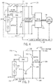
FIG. 7 schematically illustrates a drive system according to another embodiment of the invention. -
FIG. 8 schematically illustrates a drive system according incorporating an electrical switch to control power flow according to another embodiment of the invention. -
FIG. 9 schematically illustrates a drive system according incorporating an electrical switch to control power flow according to another embodiment of the invention -
FIG. 10 schematically illustrates a drive system according incorporating an electrical switch to control power flow according to another embodiment of the invention. - An arrangement of a power dense energy storage device and an energy battery is shown that provides improved transient power capability in a hybrid power drive system. A switching device for selectively connecting and disconnecting the power dense energy storage device to the drive system with an energy battery is also shown that allows for fast variation of DC link voltage and improves efficiency of the drive system.
- Referring first to
FIG. 1 , adrive system 10, such as a vehicle propulsion system, is shown according to an embodiment of the invention, with thedrive system 10 having anenergy system 11 that includes a DC/DC converter 12 and anenergy storage system 15. Theenergy storage system 15 includes a first energy storage device 14 ( ) and a secondenergy storage device 20. In an exemplary embodiment, the firstenergy storage device 14 is a high specific energy battery and the secondenergy storage device 20 is an ultracapacitor - with these energy storage devices being referred to hereafter asbattery 14 andultracapacitor 20. It is recognized, however, that in other embodiments of the invention the energy storage devices could be provided in a different form, such as the secondenergy storage device 20 being a lithium ion battery or other power dense energy storage device, and such alternate embodiments are recognized as being within the scope of the invention. - In
drive system 10, the DC/DC converter 12 connects thebattery 14 on a low voltage side of the system to a highvoltage DC link 16, with aDC link capacitor 18 optionally being provided on the DC link (dependent on the construction of DC/DC converter 12, for example) to provide filtering. Theultracapacitor 20 is also placed between thebattery 14 and the highvoltage DC link 16, with a voltage of theultracapacitor 20 being the difference between a voltage on theDC link 16 and a voltage of thebattery 14. Theultracapacitor 20 can be charged and discharged from theDC link 16. Thebattery 14 is coupled in series with theultracapacitor 20, such that a combined output power of thebattery 14 and theultracapacitor 20 can be provided to theDC link 16 for transmission to aload 21. As shown inFIG. 1 , the DC/DC converter 12 is connected to anode 21 located between thebattery 14 and theultracapacitor 20, such that a voltage output of thebattery 14 may be provided to the DC/DC converter 12, without a voltage output of theultracapacitor 20 needing to be passed through the DC/DC converter 12. The DC/DC converter 12 is further connected to anode 22 connecting theultracapacitor 20 to theDC link 16 such that, for example, a boosted output of the DC/DC converter 12 may be provided directly to theDC link 16 and combined with an output of theultracapacitor 20 for providing power to theDC link 16. - While the
energy storage system 15 ofFIG. 1 is shown with theultracapacitor 20 being positioned abovebattery 14 and adjacent tonode 22, it is recognized that the arrangement of theultracapacitor 20 andbattery 14 could be reversed. That is, according to another embodiment, thebattery 14 could be positioned above theultracapacitor 20 so as to beadjacent node 22. - The power capability of the
drive system 10 provided by the above described arrangement of the DC/DC converter 12,battery 14, and theultracapacitor 20 with theDC link 16 is illustrated inFIG. 2 . As can be seen therein, with the battery alone, the power capability is simplified a single line on the diagram, as indicated at 23. While the battery voltage is assumed to be constant for simplicity, in reality, the battery voltage decreases or increases as the discharge or charge power varies due to the internal impedance of the battery - with the battery voltage and state of charge both changing. By adding a DC/DC converter with sufficient power, the operating space of the system can be extended to cover higher voltage, as indicated at 24. That is, by adding the DC/DC converter, the limit of the system voltage is increased to the voltage limit of the DC/DC converter. Depending on the power capability of the DC/DC converter, the power capability of the battery may not be fully utilized. As shown and described inFIG. 1 , an ultracapacitor can be added to improve the power capability of the system, as indicated at 26. Ideally, the power capability of the ultracapacitor is a linear function of its terminal voltage for specified current rating. Due to its large capacitance, the ultracapacitor is able to deliver high power momentarily if pre-charged to the desired voltage level. Typically, the maximum level of charge or discharge current of the ultracapacitor is larger than that of the battery. If the power is delivered only through the series path of the battery and the ultracapacitor, the output power of the ultracapacitor is limited by the maximum current of the battery. In order to deliver higher power in or out of the ultracapacitor, the DC/DC converter can control the current injected into the node between the ultracapacitor and the battery so that current level of the ultracapacitor can be larger than the battery while the battery is charging or discharging within its own maximum current. This way, the DC/DC converter handles only the difference of current between the ultracapacitor and the battery. The same applies for the case where the current capability of the ultracapacitor is lower than the battery. - Referring now to
FIG. 3 , and with reference back toFIG. 1 , an exemplaryoperational cycle 30 of thedrive system 10 is shown. As shown at 32, thesystem 10 is initially in a standby mode, with no power transfer occurring that time. During a period where there is no load demand, as shown at 34, the DC/DC converter 12 raises the DC link voltage and charges theultracapacitor 20. Initially starting from zero voltage, the power entering theultracapacitor 20 is limited by the maximum current of the ultracapacitor. The power entering theultracapacitor 20 can also be limited by the capability of the DC/DC converter 12 or by the charging power command. Next, when the load requires power, as shown at 36, thebattery 14 provides the load with power through the DC/DC converter 12 while theultracapacitor 20 continues charging. As shown at 38, the load power is maintained, with theultracapacitor 20 then discharging to provide power, the DC/DC converter 12 bypassing the current, and thebattery 14 not providing power. At 40, thebattery 14 provides all load power through DC/DC converter 12, with the ultracapacitor voltage and DC link voltage remaining constant. When regenerative power feeds both thebattery 14 and theultracapacitor 20, as shown at 42, the ultracapacitor voltage and DC link voltage increase. When the DC/DC converter 12 shuts down, as shown at 44, thebattery 14 andultracapacitor 20 together provide load power. Then, during a period shown at 46, regenerative power feeds only theultracapacitor 20, while the battery state-of-charge (SOC) remains constant. - While the arrangement of the DC/
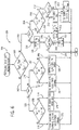
DC converter 12,battery 14, and theultracapacitor 20 with theDC link 16 provides an improved transient power capability in thedrive system 10, it is recognized that theultracapacitor 20 is always connected to theDC link 16 and thebattery 14 in thedrive system 10. Analternative drive system 100 is thus shown inFIG. 4 in which the ultracapacitor may be disconnected from theDC link 16 and thebattery 14, so as to allow the DC link voltage to be controlled to vary faster according to the need for better efficiency. - As shown in
FIG. 4 , thedrive system 100 includes anenergy system 102 comprised of anenergy storage system 106 and a bi-directional boost converter 108 - with theenergy storage system 106 including a battery 110 (e.g., high specific energy battery) and anultracapacitor 112. However, as mentioned above with respect toFIG. 1 , it is recognized that in other embodiments of the invention, other suitable energy storage devices could be substituted for thebattery 110 andultracapacitor 112, such as the ultracapacitor being replaced by a high power lithium ion battery, for example. Theenergy storage system 106 is coupled via a direct current (DC) link 114 to a DC-AC inverter 116 and aload 118 that is preferably an electric drive, such as an AC motor, but is not limited as such. In one embodiment, aDC link capacitor 104 is provided on the DC link 114 to provide filtering to power thereon, but it is recognized that in some embodiments the DC link capacitor is not required. - The
bi-directional boost converter 108 is operable to boost voltage received from the high specific-energy battery 110 andultracapacitor 112 to the DC link 114 and/or buck voltage from the DC link 114 to the high specific-energy battery 110 andultracapacitor 112. In the boost mode of operation, the combination of high specific-energy battery 108 andultracapacitor 110 transfers electrical energy tobi-directional boost converter 108, which in turn provides boosted voltage to DC link 114. That is, voltage provided on the low voltage side of energy system 102 (by battery 110) is boosted bybi-directional boost converter 108 such that the voltage provided to DC link 114 on the high voltage side ofenergy system 102 is increased. The electrical energy provided viabi-directional boost converter 108 is dynamically controlled and is dependent upon the charge capacity and requirements of thebattery 110 and/orultracapacitor 112. - Also coupled to DC link 114 is a
dynamic retarder 120.Dynamic retarder 120 acts to limit the DC voltage developed on DC link 114 whenelectric drive 118 is operated in a regenerative mode, wherein electric energy is returned to DC link 114 through DC-AC inverter 116 during a regenerative braking event. Additionally, whenelectric drive 118 operates in a regenerative braking mode,drive system 100 is configured to deliver the regenerative electrical energy through multi-channelbi-directional boost converter 108 viaDC link 114, wherein the electrical energy is then recaptured and stored in at least one of thebattery 110 andultracapacitor 112. Conventionally, in a system with only a high specific-energy battery 110 coupled through abi-directional boost converter 108, a significant portion of the regenerative energy would have to be captured in the high specific-energy battery 110 through increased current. Thus, high losses would be experienced both in the high specific-energy battery's internal resistance and also in thebi-directional boost converter 108 due to a limit in the amount of charge acceptance and voltage limits of thebattery 110. However, under the configuration shown inFIG. 4 , the losses in both thebi-directional boost converter 108 and high specific-energy battery 110 are greatly reduced. That is, the configuration ofultracapacitor 112 and high specific-energy battery 110 enables much of the regenerated energy to be captured inultracapacitor 112, rather than relying upon only high specific-energy battery 110 to capture regenerated energy. Unlike high specific-energy battery 110,ultracapacitor 112 is operable at a low state-of-charge (SOC) and is capable of rapid high-rate electrical charge acceptance. As such,ultracapacitor 112 is capable of accepting much of the regenerative power from the high voltage regenerated energy generated byelectric drive 118 during vehicle deceleration, resulting in lower electrical loss and thermal cycling stresses withinbi-directional boost converter 108 and high specific-energy battery 110, which thereby improves the overall efficiency ofdrive system 100. - While the inclusion of
ultracapacitor 112 aids to reduce losses experienced in both thebi-directional boost converter 108 and high specific-energy battery 110 (as compared to a system that does not include an ultracapacitor), it is recognized that - due to the large capacitance of the ultracapacitor 112 - the voltage of the DC link 114 cannot be changed in a short time period. That is, if theultracapacitor 112 is always connected to the DC link 114 and thebattery 110, the voltage of the DC link 114 cannot be changed in a short time period. Accordingly, in order to optimize the drive system efficiency by reducing the DC link voltage when the load power demand is low, aswitch 122 is provided in theenergy system 102 that is positioned between theultracapacitor 112 and the high voltage DC link 114, as shown inFIG. 4 . Theswitch 122 is operable to selectively connect and disconnect theultracapacitor 112 to/from the DC link 114 - with theswitch 122 thus being able to selectively disconnect theultracapacitor 112 so as to allow the DC link voltage to be varied faster and with better efficiency. Whileswitch 122 is shown inFIG. 4 as a simple, contactor-type mechanical switch, it is recognized that any suitable switch could be used - with theswitch 122 controlling the flow of current therethrough in one or both directions, as will be explained in greater detail with regard to additional embodiments of the invention. - In operation of the
drive system 100, the actuation of theswitch 122 between open and closed positions is controlled based on power requirements of theelectric drive 118 as well as power and voltage requirements/levels of thebattery 110 andultracapacitor 112 of theenergy storage system 106. In selectively utilizing theultracapacitor 112 via actuation ofswitch 122, and to enable theultracapacitor 112 to have the capability to provide and absorb power, its voltage is controlled at a nominal value Vnom. As defined herein the nominal voltage Vnom forultracapacitor 112 is a voltage value between a lowest operating voltage of the ultracapacitor, V1, and a maximum voltage of the ultracapacitor, V4. The nominal voltage Vnom is further defined as being between a demand charge threshold of the ultracapacitor, V2, that depends on the minimum amount of stored energy desired for providing transient power and a demand discharge threshold of the ultracapacitor, V3, that corresponds to the highest stored energy to allow desired energy absorbing. In operation of thedrive system 100, when the ultracapacitor voltage is higher than V3, the drive system will operate to discharge the ultracapacitor such that its voltage is reduced from V3 to Vnom whenever possible. Similarly, when the ultracapacitor voltage is lower than V2, the drive system will operate to charge the ultracapacitor such that its voltage is increased from V2 to Vnom when possible. - As shown in
FIG. 4 , avehicle system controller 125 is included indrive system 100 and is in operative communication with the energy system 102 (including DC-DC converter 108,battery 110,ultracapacitor 112 and switch 122),inverter 116 and electric, drive 118 to receive inputs therefrom and control operation thereof. Thecontroller 125 operates to control operation of components of theenergy system 102 based on power requirements of theelectric drive 118 and based on voltage levels of thebattery 110 andultracapacitor 112. More specifically,controller 125 controls operation of DC-DC converter 108 (to boost/buck voltage), controls actuation ofswitch 122 between open and closed positions, and controls charging and discharging of thebattery 110 andultracapacitor 112 based on power requirements of theelectric drive 118 and based on voltage levels of thebattery 110 andultracapacitor 112. - While the
energy storage system 106 ofFIG. 4 is shown with theultracapacitor 112 being positioned abovebattery 110 and adjacent to switch 122, it is recognized that the arrangement of theultracapacitor 112,battery 110, and switch 122could be reversed. That is, according to another embodiment, thebattery 110 could be positioned above the ultracapacitor 112 (withbattery 110 abovenode 124 andultracapacitor 112 below node 124), with the position of theswitch 122 being moved such that it remainsadjacent ultracapacitor 112 to control connection thereof to DC link 114. - Referring now to
FIG. 5 , and with continued reference toFIG. 4 , an exemplaryoperational cycle 126 of thedrive system 100 is shown (such as could be controlled by vehicle system controller 125), in order to better illustrate and describe the operation thereof. Theoperational cycle 126 begins with thesystem 100 being initially in a standby mode, as indicated at 128, with no power transfer occurring that time.Switch 122 is open during the standby mode. After standby but during a period where there is no load demand, as shown at 130, theswitch 122 is closed, with thebi-directional boost converter 108 raising the DC link voltage to charge theultracapacitor 112 to the nominal voltage, Vnom. During a period where a load power requirement is introduced that does not exceed the power available inbattery 110, as indicated at 132, theswitch 122 is opened such that the ultracapacitor voltage remains at the nominal value. During this period, thebi-directional boost converter 108 reduces the DC link voltage while thebattery 110 provides the load power, which reduces the switching loss of amotor drive converter 116 that is attached to theDC link 114. The positioning ofswitch 122 remains the same (i.e., open) during anext period 134 where the load voltage requirement increases but is still lower than the battery voltage, thebattery 110 continues to provide the load power. - In a next step of the
operational cycle 126, and as indicated at 136, the load voltage requirement increases to a level higher than the battery voltage. During this period, thebi-directional boost converter 108 functions to boost voltage provided by thebattery 110 and raise the DC link voltage to meet the voltage requirement - with theswitch 122 still remaining open. During anext period 138, the DC link voltage reaches a nominal value - with thebattery 110 continuing to provide all the load power and thebi-directional boost converter 108 continuing to boost voltage provided by thebattery 110. Also during theperiod 138, theswitch 122 is closed so as to connect theultracapacitor 112 to theDC link 114. As theultracapacitor 112 is connected to the DC link 114, a large transient load imposed by theelectric drive 118 during aperiod 140 can be handled by a combination of thebattery 110 and ultracapacitor 112 - with theultracapacitor 112 discharging power to supplement power provided by thebattery 110 in order to collectively provide increased power to meet this load. Also during theperiod 140, the DC link voltage is decreased due to the discharge of theultracapacitor 112. - As indicated at 142, during a period of the
operational cycle 126 when the load imposed by theelectric drive 118 is decreased (and after discharging of the ultracapacitor 112), thebattery 110 functions to provide load power as well as power to charge theultracapacitor 112 to its nominal voltage. More specifically, if theultracapacitor 112 is at a voltage that is approaching its demand charge threshold, V2, recharging of theultracapacitor 112 is performed via power from thebattery 110. At aperiod 144 when there is a large regenerative transient power present in thedrive system 100, such as might occur during regenerative braking of a motor drive for example, the DC link voltage will be above the nominal value, and thus recharging power is provided to both thebattery 110 and theultracapacitor 112. At a conclusion of theperiod 144,ultracapacitor 112 is recharged to a high voltage, such as a voltage at the demand discharge threshold, V3, or approaching the maximum voltage, V4. Thus, in anext period 146 where a load power requirement is again introduced byelectric drive 118 with a small load voltage requirement, theultracapacitor 112 discharges to provide load power as well as provide a small power to charge thebattery 110. Also during thisperiod 146, the DC link voltage decreases to nominal value. - In each of
periods switch 122 is in a closed position such that theultracapacitor 112 is connected to theDC link 114. But upon reaching a time where the DC link voltage has decreased to a nominal value and the load power demand is lower than the capability of thebattery 110, aperiod 148 is initiated by opening theswitch 122 in order to disconnect theultracapacitor 112 from theDC link 114. Duringperiod 148, thebi-directional boost converter 108 reduces the DC link voltage to the battery voltage, such that only thebattery 110 provides load power. At the same time, the switching loss of themotor drive converter 116 can be reduced because of the reduced DC bus voltage. During asubsequent period 150 where the DC link voltage remains at the battery voltage, thebattery 110 continues to provide the load power, and theoperational cycle 126 then concludes atperiod 152 where a regenerative power is again present. Inperiod 152, theswitch 122 remains open, with the DC link voltage being equal to the battery voltage and regenerative power from theelectric drive 118 feeding thebattery 110 at low voltage. - Referring now to
FIG. 6 , and with continued reference back toFIG. 4 , atechnique 156 for operating theenergy system 102 indrive system 100 is described, with it being recognized that thetechnique 156 could be implemented byvehicle system controller 125, for example. At an initiation oftechnique 156, a load requirement of the system load (i.e., electric drive 118) is first measured or otherwise determined atSTEP 158. The load power requirement is then compared to a power capability of thebattery 110 atSTEP 160, with a determination being made as to whether a command or requirement for load power is greater than a power capability of the battery (Pload>Pbatt) or whether a power of the battery is such that it is capable of receiving power being generated by the load (Pload<P-batt), such as during regenerative braking power. - If it is determined at
STEP 160 either that the load power requirement is greater than a power of the battery or that the load can provide regenerative power to the battery, as indicated at 162, then the technique continues to STEP 164 - where a determination is made as to whether theswitch 122 is presently in a closed position (i.e., SW=1). If it is determined atSTEP 164 that the switch is closed, as indicated at 166, then the technique continues to STEP 168 with a determination of whether a voltage of theultracapacitor 112 is less than a lowest operating voltage of the ultracapacitor, V1, or whether a voltage of theultracapacitor 112 is greater than a maximum voltage of the ultracapacitor, V4. If it is determined atSTEP 168 that a voltage of theultracapacitor 112 is less than V1 or greater than V4, as indicated at 170, then the technique continues to STEP 172 - where a charging or discharging of theultracapacitor 112 is prevented. Also atSTEP 172, the power command for providing power to theelectric drive 118 is reduced. - If instead it is determined at
STEP 168 that a voltage of theultracapacitor 112 is between the voltages V1 and V4 (i.e., is not less than V1 or is not greater than V4), as indicated at 174, then the technique continues to STEP 176 - where power is delivered to or received from theelectric drive 118 frombattery 110 and fromultracapacitor 112, within prescribed limits of theultracapacitor 112. That is, atSTEP 176, power is delivered to or received from theelectric drive 118 by theultracapacitor 112 andbattery 110 as long as the voltage of theultracapacitor 112 remains above the demand charge threshold of the ultracapacitor, V2. - Referring back now to STEP 164, if it is determined at
STEP 164 that theswitch 122 is open, as indicated at 178, then the technique continues atSTEP 180 with a determination of whether a voltage of theultracapacitor 112 is less than the lowest operating voltage of the ultracapacitor, V1, or whether a voltage of theultracapacitor 112 is greater than the maximum voltage of the ultracapacitor, V4. If it is determined atSTEP 180 that a voltage of theultracapacitor 112 is less than V1 or greater than V4, as indicated at 182, then the technique continues to STEP 184 - where theswitch 122 is left open and a power command for the load is reduced, so as to bring the power command below a power available from thebattery 110. - If instead it is determined at
STEP 180 that a voltage of theultracapacitor 112 is between the voltages V1 and V4 (i.e., is not less than V1 or is not greater than V4), as indicated at 186, then the technique continues to STEP 188 - where the DC link voltage is controlled to a level where it matches the sum of voltage ofbattery 110 andultracapacitor 112, then theswitch 122 is closed. After theswitch 122 is closed, the power can be provided or absorbed by a combination of thebattery 110 and theultracapacitor 112. The ultracapacitor112 is thus ready to be charged or discharged. - Referring back now to STEP 160, if it is determined at
STEP 160 either that the load power requirement is less than a power of the battery or that the load can provide regenerative power to the battery, as indicated at 162, as indicated at 190, then the technique continues to STEP 192 - where a determination is made as to whether theswitch 122 is presently in a closed position (i.e., SW=1). If it is determined atSTEP 192 that the switch is closed, as indicated at 194, then the technique continues to STEP 196, where the DC link voltage is controlled/modified to a nominal DC link voltage value, VDCnom, that is equivalent to a sum of the nominal battery voltage, Vbattnom, and the nominal ultracapacitor voltage, Vnom. Upon modifying the DC link voltage to a nominal DC link voltage value, VDCnom, the technique continues to STEP 198, where a determination is made as to whether the voltage requirement of theload 118 is less than the voltage ofbattery 110. If it is determined atSTEP 198 that the voltage requirement of theload 118 is less than the voltage ofbattery 110, as indicated at 200, then the technique continues to STEP 202, where theswitch 122 is opened so as to disconnect the ultracapacitor from theDC link 114. - Referring back to
STEP 192, if it is determined atSTEP 192 that theswitch 122 is open, as indicated at 204, then the technique continues atSTEP 206 with a determination of whether a voltage of theultracapacitor 112 is greater than the demand discharge voltage threshold, V3, or less than the demand charge voltage threshold of, V2 of the ultracapacitor 112 (i.e., whether the voltage of the ultracapacitor is between V2 and V3). If it is determined atSTEP 206 that a voltage of theultracapacitor 112 is not between the voltage thresholds V2 and V3 (i.e., is greater than V3 or less than V2), as indicated at 208, then the technique continues to STEP 210 - where theswitch 122 is closed and theenergy system 102 is controlled to so as to modify the DC link voltage to a level where it matches the voltage of theultracapacitor 112. - If it is determined at
STEP 206 that a voltage of theultracapacitor 112 is between the voltage thresholds V2 and V3, as indicated at 212, then the technique continues atSTEP 214 with a determination of whether a voltage requirement of theelectric drive 118 is less than the voltage of thebattery 110. If it is determined atSTEP 214 that a voltage requirement of theelectric drive 118 is less than the voltage of thebattery 110, as indicated at 216, then thebi-directional boost converter 108 is shut down, as routing of voltage through thebi-directional boost converter 108 is not required to meet the voltage requirement of theelectric drive 118. Conversely, if it is determined atSTEP 214 that a voltage requirement of theelectric drive 118 is greater than the voltage of thebattery 110, as indicated at 220, then the DC link voltage is controlled/modified so as to meet the voltage demand of theelectric drive 118, with thebi-directional boost converter 108 modifying (i.e., boosting) a voltage output bybattery 110 before providing the voltage to the DC bus. While controlling the DC link voltage atSTEP 222, theswitch 122 is left open - such that theultracapacitor 112 remains disconnected from the DC link 114, thereby allowing the DC link voltage to be varied faster than if theultracapacitor 112 was connected to the DC link. - In performing
technique 156, thebi-directional boost converter 108 is operated so as to keep the ultracapacitor voltage at the nominal value, Vnom, whenever possible. By maintaining the ultracapacitor at the nominal voltage, Vnom, the ultracapacitor is available to either provide or absorb energy at any given time. In addition, whenever the load does not require voltage higher than the nominal DC link voltage (Vbattnom + Vnom), the ultracapacitor is disconnected from the DC link so that the system efficiency can be optimized. - Referring now to
FIG. 7 , it is recognized that aswitch 122 may be utilized with an arrangement of energy storage devices that differs from those in thedrive system 100 ofFIG. 4 . InFIG. 7 , anenergy system 226 for use in a drive system is shown according to another embodiment of the invention. Theenergy system 226 is comprised of anenergy storage system 230 and a bi-directional boost converter 232 - with theenergy storage system 230 including abattery 234 and anultracapacitor 236. As shown inFIG. 7 , thebattery 234 is positioned on alow voltage side 237 of theenergy system 226 and theultracapcitor 234 is positioned on ahigh voltage side 239 of theenergy system 226, with theultracapacitor 234 being selectively connected to aDC link 238 by way ofswitch 122. Theswitch 122 allows for theultracapacitor 234 to be selectively connected and disconnected from the DC link 238 so as to allow the DC link voltage to be controlled to vary faster according to the need for better efficiency. In operation, switching ofswitch 122 can be performed as set forth in detail in thetechnique 156 ofFIG. 6 . - While the
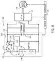
energy systems FIGS. 4 and 7 are shown as including a switch therein in the form of a mechanical switch or contact movable between open and closed positions, it is recognized that theenergy systems FIGS. 8-10 , examples of different switching devices that might be utilized in an energy system are shown according to embodiments of the invention. The type of switching device provided in the energy system can be selected based on the need/desire for the switching device to block and conduct in a single direction or in both directions. - Referring first to
FIG. 8 , aswitching device 240 is illustrated that is controllable to block and conduct current in both directions - with theswitching device 240 in the form of an arrangement of a pair of switches each including asingle IGBT 242 withanti-paralleled diode 244. The voltage of the DC link 114 and theultracapacitor 112 can be fully decoupled. The feasible operating DC link voltage is between the battery voltage and the maximum DC link voltage. This configuration enables full capability of converter efficiency optimization during partial load condition. The ultracapacitor maximum voltage can be selected to be equal or lower than the difference between the maximum DC link voltage and the battery voltage. To be able to deliver or receive high transient power, the DC link 114 has to be connected to theultracapacitor 112. Therefore, the operating DC link voltage for delivering high transient power is the battery voltage plus the ultracapacitor voltage. The partition of load can be freely controlled by the DC/DC converter 108. Any combination of charge and discharge is allowed to optimize the overall performance ofdrive system 100 andenergy system 102, including power capability and system efficiency. At partial load condition, the DC link voltage is controlled to optimize the system efficiency. During partial load operation, all the load power is delivered or received by thebattery 110. - Referring next to
FIGS. 9 and10 , switchingdevices single IGBT 242 withanti-paralleled diode 244 are provided - with the diodes in opposing directions in theswitching device 246 and theswitching device 248. The switchingdevices diode 244 therein. For switchingdevice 246 ofFIG. 9 , the DC link 114 will automatically charge theultracapacitor 112 when the DC link voltage is higher than the sum of battery and ultracapacitor voltage. Because the DC link capacitance is much smaller than that of theultracapacitor 112, the DC link voltage can be changed quickly. However, theultracapacitor 112 requires more much energy and time to charge or discharge to reach desired voltage. That is, the DC link voltage can only be lower than the sum of battery and ultracapacitor voltage, and the maximum DC link voltage is the sum of the battery voltage and the maximum voltage of the ultra-capacitor. With switchingdevice 246, the discharge of theultracapacitor 112 can be freely controlled.Switching device 246 thus provides a lower cost alternative to switching device 240 (FIG. 8 ), while still providing a reduction of switching losses by reducing the DC link voltage. Similar to switchingdevice 240, switchingdevice 246 allows for high power transient power to be delivered or received by the ultra-capacitor 112 andbattery 110, and partial load to be delivered only by thebattery 110. - In
FIG. 10 , theswitching device 248 automatically discharges theultracapacitor 112 whenever the DC link voltage is lower than the sum of battery and ultra-capacitor voltage. The DC link voltage can be controlled to between sum of battery and ultra-capacitor voltage and the maximum DC link voltage. Like in switchingdevice 240, the ultracapacitor maximum voltage can be selected to be equal or lower than the difference between the maximum DC link voltage and the battery voltage. Thus, with switchingdevice 248, the DC link voltage is raised to reduce the load current. Systems whose efficiency will benefit from reduced current can utilizedswitching device 248, with reduced cost compared to switching device 240 (FIG. 8 ). As with switchingdevice 240, switchingdevice 248 allows for high power transient power to be delivered or received by theultracapacitor 112 andbattery 110, and partial load is only delivered by thebattery 110. - Beneficially, embodiments of the invention thus provide an arrangement of a DC/DC converter, battery, and ultracapacitor, with the ultracapacitor allowing for an improved transient power capability in a drive system so that the size of the battery and DC/DC converter can be minimized. A mechanical or electrical switch may be implemented to selectively couple and decouple the ultracapacitor from the DC link in order to enable efficiency improvement compared to a system without a switch for the ultracapacitor. Such a can be selected based on the need/desire for the switching device to block and conduct in a single direction or in both directions.
- Therefore, according to one embodiment of the invention, a drive system includes a load, a direct current (DC) link electrically coupled to the load, an energy storage system having a first energy storage device and a second energy storage device arranged in series, and a bi-directional DC-DC converter electrically coupled to the DC link and to the energy storage system, the bi-directional DC-DC converter being connected to a node located between the first energy storage device and the second energy storage device and to a node connecting the second energy storage device to the DC link.
- According to another embodiment of the invention, an energy system for providing power to a load includes an energy storage system electrically coupleable to the load through a DC link, with the energy storage system further including a first energy storage device and a second energy storage device arranged in series with the first energy storage device, the second energy storage device being coupled directly to the DC link. The energy system also includes a bi-directional DC-DC converter electrically coupled to the DC link and to the energy storage system, with the bi-directional DC-DC converter connecting the first energy storage device to the DC link such that power to and from the first energy storage device is selectively routed through the bi-directional DC-DC converter and with the bi-directional DC-DC converter positioned such that power to and from the second energy storage device bypasses the DC-DC converter.
- According to yet another embodiment of the invention, a drive system includes a load, a direct current (DC) link electrically coupled to the load, an energy storage system having a first energy storage device and a second energy storage device, a bi-directional DC-DC converter positioned such that the first energy storage device is connected to the DC link through the bi-directional DC-DC converter and the second energy storage device is coupled directly to the DC link, and a switch positioned between the second energy storage device and the DC link, the switch being operable in a closed position and an open position to selectively connect and disconnect the second energy storage device to and from the DC link, respectively.
- According to still another embodiment of the invention, a drive system includes a load, a direct current (DC) link electrically coupled to the load, a first energy storage device positioned on a low voltage side of the drive system, a second energy storage device positioned on a high voltage side of the drive system, and a bi-directional DC-DC converter positioned between the low voltage side and the high voltage side to decouple the first energy storage device from the DC link, the bi-directional DC-DC converter boosting voltage from the first energy storage device for providing to the DC link on the high voltage side. The drive system also includes a switch positioned between the second energy storage device and the DC link, the switch being operable in a closed position and an open position to selectively connect and disconnect the second energy storage device to and from the DC link, respectively.
- This written description uses examples to disclose the invention, including the best mode, and also to enable any person skilled in the art to practice the invention, including making and using any devices or systems and performing any incorporated methods. The patentable scope of the invention is defined by the claims, and may include other examples that occur to those skilled in the art. Such other examples are intended to be within the scope of the claims if they have structural elements that do not differ from the literal language of the claims, or if they include equivalent structural elements with insubstantial differences from the literal languages of the claims.
- While the invention has been described in detail in connection with only a limited number of embodiments, it should be readily understood that the invention is not limited to such disclosed embodiments. Rather, the invention can be modified to incorporate any number of variations, alterations, substitutions or equivalent arrangements not heretofore described, but which are commensurate with the spirit and scope of the invention. Additionally, while various embodiments of the invention have been described, it is to be understood that aspects of the invention may include only some of the described embodiments. Accordingly, the invention is not to be seen as limited by the foregoing description, but is only limited by the scope of the appended claims.
- Various aspects and embodiments of the present invention are defined by the following numbered clauses:
- 1. A drive system comprising:
- a load;
- a direct current (DC) link electrically coupled to the load;
- an energy storage system comprising a first energy storage device and a second energy storage device, wherein the first energy storage device and the second energy storage device are arranged in series; and
- a bi-directional DC-DC converter electrically coupled to the DC link and to the energy storage system, the bi-directional DC-DC converter being connected to a node located between the first energy storage device and the second energy storage device and to a node connecting the second energy storage device to the DC link.
- 2. The drive system of
clause 1 further comprising a switch positioned between the second energy storage device and the DC link, the switch being operable in a closed position and an open position to selectively connect and disconnect the second energy storage device to and from the DC link, respectively. - 3. The drive system of
clause 1 orclause 2 further comprising a controller configured to control operation of the DC-DC converter and the switch based on power requirements of the load and based on voltage levels of the first and second energy storage devices. - 4. The drive system of any preceding clause wherein the second energy storage device comprises an ultracapacitor; and
wherein the controller is configured to control a charging and discharging of the ultracapacitor to maintain the ultracapcitor at a nominal voltage level, the nominal voltage level comprising a voltage level between a demand charge threshold of the ultracapacitor comprising a minimum amount of stored energy for providing transient power from the ultracapacitor and a demand discharge threshold of the ultracapacitor comprising a highest stored energy of the ultracapacitor that allows for energy absorbing. - 5. The drive system of any preceding clause wherein the controller is configured to:
- cause the ultracapacitor to discharge when a voltage thereof is higher than the demand discharge threshold, so as to bring the voltage of the ultracapacitor down to the nominal voltage level; and
- cause the ultracapacitor to be charged when a voltage thereof is lower than the demand charge threshold, so as to so as to bring the voltage of the ultracapacitor up to the nominal voltage level.
- 6. The drive system of any preceding clause wherein the controller controls operation of the DC-DC converter and actuation of the switch between the closed position and the open position to maintain the ultracapcitor at the nominal voltage level.
- 7. The drive system of any preceding clause wherein the controller is configured to:
- determine a load voltage requirement of the load;
- compare the load voltage requirement to a nominal DC link voltage value, the nominal DC link voltage value equivalent to a sum of the ultracapacitor nominal voltage level and a nominal voltage value of the first energy storage device;
- cause the switch to operate in the open position if the load voltage requirement is less than the nominal DC link voltage value; and
- cause the switch to operate in the closed position if the load voltage requirement is greater than the nominal DC link voltage value.
- 8. The drive system of any preceding clause wherein, when the voltage of the ultracapacitor is higher than the demand discharge threshold, the controller causes the ultracapacitor to discharge to provide at least one of a load power and a first energy storage device recharging power, with the providing of the at least one of the load power and the first energy storage device recharging power being based on the comparison of the load voltage requirement to a nominal DC link voltage value.
- 9. The drive system of any preceding clause wherein the switch comprises one of a contactor-type mechanical switch and an electrical switch, with the switch controlling current flow in one direction or in both directions therethrough.
- 10. The drive system of any preceding clause wherein the first energy storage device comprises a battery.
- 11. An energy system for providing power to a load, the energy system comprising:
- an energy storage system electrically coupleable to the load through a DC link, the energy storage system comprising:
- a first energy storage device; and
- a second energy storage device arranged in series with the first energy storage device, the second energy storage device being coupled directly to the DC link; and
- a bi-directional DC-DC converter electrically coupled to the DC link and to the energy storage system, with the bi-directional DC-DC converter connecting the first energy storage device to the DC link such that power to and from the first energy storage device is selectively routed through the bi-directional DC-DC converter and with the bi-directional DC-DC converter positioned such that power to and from the second energy storage device bypasses the DC-DC converter.
- an energy storage system electrically coupleable to the load through a DC link, the energy storage system comprising:
- 12. The energy system of any preceding clause wherein the bi-directional DC-DC converter is connected to a node located between the first energy storage device and the second energy storage device and to a node connecting the second energy storage device to the DC link.
- 13. The energy system of any preceding clause further comprising a switch positioned between the second energy storage device and the DC link, the switch being operable in a closed position and an open position to selectively connect and disconnect the second energy storage device to and from the DC link, respectively.
- 14. The energy system of any preceding clause wherein the first energy storage device is positioned on a low voltage side of the energy system and the second energy storage device is positioned on a high voltage side of the energy system, with the bi-directional DC-DC converter boosting voltage from first energy storage device for providing to the DC link and with the second energy storage device being selectively coupled directly to the DC link via the switch.
- 15. The energy system of any preceding clause wherein the switch comprises one of a contactor-type mechanical switch and an electrical switch, with the switch controlling current flow in one direction or in both directions therethrough.
- 16. A drive system comprising:
- a load;
- a direct current (DC) link electrically coupled to the load;
- an energy storage system comprising a first energy storage device and a second energy storage device;
- a bi-directional DC-DC converter positioned such that the first energy storage device is connected to the DC link through the bi-directional DC-DC converter and the second energy storage device is coupled directly to the DC link; and
- a switch positioned between the second energy storage device and the DC link, the switch being operable in a closed position and an open position to selectively connect and disconnect the second energy storage device to and from the DC link, respectively.
- 17. The drive system of any preceding clause further comprising a DC link capacitor coupled to the DC link, and wherein the first and second energy storage devices of the second energy storage system comprise a battery and an ultracapacitor, respectively.
- 18. The drive system of any preceding clause further comprising a controller configured to control operation of the DC-DC converter and the switch based on power requirements of the load and based on voltage levels of the battery and the ultracapacitor.
- 19. The drive system of any preceding clause wherein the controller is configured to maintain the ultracapacitor at a nominal voltage level that is between a demand charge threshold of the ultracapacitor comprising a minimum amount of stored energy for providing transient power from the ultracapacitor and a demand discharge threshold of the ultracapacitor comprising a highest stored energy of the ultracapacitor that allows for energy absorbing, wherein maintaining the ultracapacitor at the nominal voltage level comprises:
- causing the ultracapacitor to discharge when a voltage thereof is higher than the demand discharge threshold, so as to bring the voltage of the ultracapacitor down to the nominal voltage level; and
- causing the ultracapacitor to be charged when a voltage thereof is lower than the demand charge threshold, so as to so as to bring the voltage of the ultracapacitor up to the nominal voltage level.
- 20. The drive system of any preceding clause wherein the controller is configured to:
- determine a load voltage requirement of the load;
- compare the load voltage requirement to a nominal DC link voltage value, the nominal DC link voltage value equivalent to a sum of the ultracapacitor nominal voltage level and a nominal voltage value of the battery;
- cause the switch to operate in the open position if the load voltage requirement is less than the nominal DC link voltage value; and
- cause the switch to operate in the closed position if the load voltage requirement is greater than the nominal DC link voltage value.
- 21. The drive system of any preceding clause wherein, when the voltage of the ultracapacitor is higher than the demand discharge threshold, the controller causes the ultracapacitor to discharge to provide at least one of a load power and a battery recharging power, with the providing of the at least one of the load power and the battery recharging power being based on the comparison of the load voltage requirement to a nominal DC link voltage value.
- 22. A drive system comprising:
- a load;
- a direct current (DC) link electrically coupled to the load;
- a first energy storage device positioned on a low voltage side of the drive system;
- a second energy storage device positioned on a high voltage side of the drive system;
- a bi-directional DC-DC converter positioned between the low voltage side and the high voltage side to decouple the first energy storage device from the DC link, the bi-directional DC-DC converter boosting voltage from the first energy storage device for providing to the DC link on the high voltage side; and
- a switch positioned between the second energy storage device and the DC link, the switch being operable in a closed position and an open position to selectively connect and disconnect the second energy storage device to and from the DC link, respectively.
Claims (15)
- A drive system (10, 100) comprising:a load (118);a direct current (DC) link (16, 114) electrically coupled to the load (118);an energy storage system (15, 106) comprising a first energy storage device (14, 110) and a second energy storage device (20, 112), wherein the first energy storage device (14, 110) and the second energy storage device (20, 112) are arranged in series; anda bi-directional DC-DC converter (12, 108) electrically coupled to the DC link (16, 114) and to the energy storage system (15, 106), the bi-directional DC-DC converter being connected to a node (21, 124) located between the first energy storage device (14, 110) and the second energy storage device (20, 112) and to a node (22) connecting the second energy storage device (20, 112) to the DC link (16, 114).
- The drive system (10, 100) of claim 1 further comprising a switch (122) positioned between the second energy storage device (20, 112) and the DC link (16, 114), the switch (122) being operable in a closed position and an open position to selectively connect and disconnect the second energy storage device (20, 112) to and from the DC link (16, 114), respectively.
- The drive system (10, 100) of claim 1 or 2 further comprising a controller (125) configured to control operation of the DC-DC converter (12, 108) and the switch (122) based on power requirements of the load (118) and based on voltage levels of the first and second energy storage devices (15, 20).
- The drive system (10, 100) of any preceding claim, wherein the second energy storage device (20, 112) comprises an ultracapacitor; and
wherein the controller (125) is configured to control a charging and discharging of the ultracapacitor (20, 112) to maintain the ultracapcitor (20, 112) at a nominal voltage level, the nominal voltage level comprising a voltage level between a demand charge threshold of the ultracapacitor (20, 112) comprising a minimum amount of stored energy for providing transient power from the ultracapacitor (20, 112) and a demand discharge threshold of the ultracapacitor (20, 112) comprising a highest stored energy of the ultracapacitor (20, 112) that allows for energy absorbing. - The drive system (10, 100) of any preceding claim, wherein the controller (125) is configured to:cause the ultracapacitor (20, 112) to discharge when a voltage thereof is higher than the demand discharge threshold, so as to bring the voltage of the ultracapacitor (20, 112) down to the nominal voltage level; andcause the ultracapacitor (20, 112) to be charged when a voltage thereof is lower than the demand charge threshold, so as to so as to bring the voltage of the ultracapacitor (20, 112) up to the nominal voltage level.
- The drive system (10, 100) of any preceding claim, wherein the controller (125) controls operation of the DC-DC converter (12, 108) and actuation of the switch (122) between the closed position and the open position to maintain the ultracapcitor (20, 112) at the nominal voltage level.
- The drive system (10, 100) of any preceding claim, wherein the controller (125) is configured to:determine a load voltage requirement of the load (118);compare the load voltage requirement to a nominal DC link voltage value, the nominal DC link voltage value equivalent to a sum of the ultracapacitor nominal voltage level and a nominal voltage value of the first energy storage device (14, 110);cause the switch (122) to operate in the open position if the load voltage requirement is less than the nominal DC link voltage value; andcause the switch (122) to operate in the closed position if the load voltage requirement is greater than the nominal DC link voltage value.
- The drive system (10, 100) of any preceding claim, wherein, when the voltage of the ultracapacitor (20, 112) is higher than the demand discharge threshold, the controller (125) causes the ultracapacitor (20, 112) to discharge to provide at least one of a load power and a first energy storage device recharging power, with the providing of the at least one of the load power and the first energy storage device recharging power being based on the comparison of the load voltage requirement to a nominal DC link voltage value.
- The drive system (10, 100) of any preceding claim, wherein the switch (122) comprises one of a contactor-type mechanical switch and an electrical switch, with the switch (122) controlling current flow in one direction or in both directions therethrough.
- The drive system (10, 100) of any preceding claim, wherein the first energy storage device (14, 110) comprises a battery.
- An energy system (11, 102) for providing power to a load (118), the energy system (11, 102) comprising:an energy storage system (15, 106) electrically coupleable to the load (118) through a DC link (16, 114), the energy storage system (15, 106) comprising:a first energy storage device (14, 110); anda second energy storage device (20, 112) arranged in series with the first energy storage device (14, 110), the second energy storage device (20, 112) being coupled directly to the DC link (16, 114); anda bi-directional DC-DC converter (12, 108) electrically coupled to the DC link (16, 114) and to the energy storage system (15, 106), with the bi-directional DC-DC converter (12, 108) connecting the first energy storage device (14, 110) to the DC link (16, 114) such that power to and from the first energy storage device (14, 110) is selectively routed through the bi-directional DC-DC converter (12, 108) and with the bi-directional DC-DC converter (12, 108) positioned such that power to and from the second energy storage device (20, 112) bypasses the DC-DC converter (12, 108).
- The energy system (11, 102) of claim 11 wherein the bi-directional DC-DC converter (12, 108) is connected to a node (21, 124) located between the first energy storage device (14, 110) and the second energy storage device (20, 112) and to a node (22) connecting the second energy storage device (20, 112) to the DC link (16, 114).
- The energy system (11, 102) of claim 11 or claim 12, further comprising a switch (122) positioned between the second energy storage device (20, 112) and the DC link (16, 114), the switch (122) being operable in a closed position and an open position to selectively connect and disconnect the second energy storage device (20, 112) to and from the DC link (16, 114), respectively.
- The energy system (11, 102) of any of claims 11 to 13, wherein the first energy storage device (14, 110) is positioned on a low voltage side of the energy system (11, 102) and the second energy storage device (20, 112) is positioned on a high voltage side of the energy system (11, 102), with the bi-directional DC-DC converter (12, 108) boosting voltage from first energy storage device (14, 110) for providing to the DC link (16, 114) and with the second energy storage device (20, 112) being selectively coupled directly to the DC link (16, 114) via the switch (122).
- The energy system (11, 102) of any of claims 11 to 14, wherein the switch (122) comprises one of a contactor-type mechanical switch and an electrical switch, with the switch (122) controlling current flow in one direction or in both directions therethrough.
Applications Claiming Priority (1)
| Application Number | Priority Date | Filing Date | Title |
|---|---|---|---|
| US14/838,485 US10272788B2 (en) | 2015-08-28 | 2015-08-28 | Hybrid system with multiple energy storage devices |
Publications (1)
| Publication Number | Publication Date |
|---|---|
| EP3135527A1 true EP3135527A1 (en) | 2017-03-01 |
Family
ID=56851430
Family Applications (1)
| Application Number | Title | Priority Date | Filing Date |
|---|---|---|---|
| EP16185846.9A Ceased EP3135527A1 (en) | 2015-08-28 | 2016-08-26 | Hybrid system with multiple energy storage devices |
Country Status (5)
| Country | Link |
|---|---|
| US (1) | US10272788B2 (en) |
| EP (1) | EP3135527A1 (en) |
| JP (1) | JP7038469B2 (en) |
| KR (1) | KR102530203B1 (en) |
| CN (1) | CN106476635B (en) |
Cited By (1)
| Publication number | Priority date | Publication date | Assignee | Title |
|---|---|---|---|---|
| EP4007155A1 (en) * | 2020-11-27 | 2022-06-01 | ACD Antriebstechnik GmbH | Energy storage with current source circuit |
Families Citing this family (31)
| Publication number | Priority date | Publication date | Assignee | Title |
|---|---|---|---|---|
| US9878635B1 (en) * | 2013-02-13 | 2018-01-30 | University Of Maryland | Powertrain system in plug-in electric vehicles |
| US10384559B2 (en) * | 2014-10-22 | 2019-08-20 | Ge Global Sourcing Llc | System and method for motor system control |
| CN106143170B (en) * | 2015-03-31 | 2020-11-17 | 通用电气公司 | Energy storage system with range extender and energy management control method |
| US10374543B2 (en) * | 2015-08-29 | 2019-08-06 | Abb Schweiz Ag | Ultracap-based solutions for ride-through of synchronous machine drives |
| EP3560060B1 (en) * | 2016-12-20 | 2020-12-02 | ABB Power Grids Switzerland AG | High power flash battery system and method thereof |
| PL3360719T3 (en) * | 2017-02-09 | 2021-04-19 | Samsung Sdi Co., Ltd | Dual power supply system |
| JP6966871B2 (en) * | 2017-05-19 | 2021-11-17 | 株式会社Subaru | Battery system |
| WO2018222672A1 (en) | 2017-05-31 | 2018-12-06 | General Electric Company | Control system and method for an energy storage system |
| US10545552B2 (en) | 2017-06-30 | 2020-01-28 | Hamilton Sundstrand Corporation | HESM parallel response mode |
| US10630420B2 (en) | 2017-06-30 | 2020-04-21 | Hamilton Sunstrand Corporation | Hybrid energy storage modules for directed energy systems |
| US10875397B2 (en) | 2017-06-30 | 2020-12-29 | Hamilton Sundstrand Corporation | HESM fast recharge algorithm |
| US10814740B2 (en) | 2017-06-30 | 2020-10-27 | Hamilton Sundstrand Corporation | HESM high pulse power algorithm |
| WO2019040037A1 (en) * | 2017-08-21 | 2019-02-28 | General Electric Company | Method and system for controlling integration of dc power source in hybrid power generation system |
| CN109755973B (en) * | 2017-11-01 | 2022-06-24 | 北京德意新能科技有限公司 | Flexible parallel device suitable for energy storage battery |
| CN108075540B (en) * | 2017-12-15 | 2021-03-26 | 电子科技大学 | High-power energy power system for helicopter and control method |
| US11431177B2 (en) | 2018-03-14 | 2022-08-30 | Hamilton Sundstrand Corporation | Hybrid energy storage module systems and methods of discharging energy storage modules |
| CN108482153A (en) * | 2018-03-28 | 2018-09-04 | 吉利汽车研究院(宁波)有限公司 | Hybrid vehicle is for electric installation, system and automobile |
| US11565821B2 (en) | 2018-07-30 | 2023-01-31 | Raytheon Technologies Corporation | Hybrid energy storage system control for an aircraft engine |
| US11401041B2 (en) | 2018-07-30 | 2022-08-02 | Raytheon Technologies Corporation | Hybrid electric power distribution and control for an aircraft |
| JP7049584B2 (en) * | 2018-10-02 | 2022-04-07 | マツダ株式会社 | Vehicle drive |
| JP7281080B2 (en) * | 2018-10-19 | 2023-05-25 | マツダ株式会社 | vehicle drive |
| JP7144738B2 (en) * | 2018-10-19 | 2022-09-30 | マツダ株式会社 | vehicle drive |
| KR102114124B1 (en) * | 2018-11-16 | 2020-06-17 | 학교법인 송원대학교 | Wireless Power Transmission Wirless Trolley Applied Speed Control Algorithm For Meeting The Charge Amount In The Dynamic Charge Interval And The Static Charge Interval |
| US10946746B2 (en) | 2019-01-28 | 2021-03-16 | Ford Global Technologies, Llc | Vehicle power system including ultra-capacitor for mitigating transient current events |
| JP7168912B2 (en) * | 2019-02-05 | 2022-11-10 | マツダ株式会社 | vehicle power system |
| KR20200134349A (en) * | 2019-05-20 | 2020-12-02 | 현대자동차주식회사 | Breaking control system and method for vehicle |
| CN110588357B (en) * | 2019-09-27 | 2022-09-13 | 重庆交通大学 | Urban rail train hybrid energy storage system and method based on automatic driving curve |
| CN110758120A (en) * | 2019-11-13 | 2020-02-07 | 北京理工大学 | Pure electric vehicle drive control method |
| CN110768342B (en) * | 2019-11-28 | 2021-03-19 | 东莞铭普光磁股份有限公司 | Energy storage device and charging and discharging system |
| WO2021117216A1 (en) * | 2019-12-13 | 2021-06-17 | ヤマハ発動機株式会社 | Straddled vehicle |
| CN115476703B (en) * | 2022-09-23 | 2023-10-31 | 首凯高科技(江苏)有限公司 | Composite power supply system suitable for electric vehicle power system |
Citations (3)
| Publication number | Priority date | Publication date | Assignee | Title |
|---|---|---|---|---|
| US6323608B1 (en) * | 2000-08-31 | 2001-11-27 | Honda Giken Kogyo Kabushiki Kaisha | Dual voltage battery for a motor vehicle |
| US20140084817A1 (en) * | 2010-07-20 | 2014-03-27 | Vijay Bhavaraju | Method of energy and power management in dynamic power systems with ultra-capacitors (super capacitors) |
| US20140265559A1 (en) * | 2013-03-15 | 2014-09-18 | Levant Power Corporation | Vehicular high power electrical system |
Family Cites Families (12)
| Publication number | Priority date | Publication date | Assignee | Title |
|---|---|---|---|---|
| JP2002330545A (en) * | 2001-04-27 | 2002-11-15 | Nissan Motor Co Ltd | Power unit |
| US7595597B2 (en) | 2006-01-18 | 2009-09-29 | General Electric Comapany | Vehicle propulsion system |
| US7990117B2 (en) | 2007-07-06 | 2011-08-02 | Northem Power Systems, Inc. | Low-loss control of DC-DC converters in an energy storage system |
| JP2010068650A (en) * | 2008-09-11 | 2010-03-25 | Autonetworks Technologies Ltd | Power system |
| US8026638B2 (en) | 2009-08-11 | 2011-09-27 | General Electric Company | System for multiple energy storage and management and method of making same |
| US9331499B2 (en) * | 2010-08-18 | 2016-05-03 | Volterra Semiconductor LLC | System, method, module, and energy exchanger for optimizing output of series-connected photovoltaic and electrochemical devices |
| KR101168078B1 (en) | 2010-12-17 | 2012-07-24 | 한국에너지기술연구원 | Multi-input bidirectional dc-dc converter |
| US20120194133A1 (en) | 2011-01-31 | 2012-08-02 | National Semiconductor Corporation | Active cell balancing using independent energy transfer bus for batteries or other power supplies |
| US9444275B2 (en) | 2011-08-31 | 2016-09-13 | North Carolina State University | Intelligent integrated battery module |
| US9440600B2 (en) | 2012-09-20 | 2016-09-13 | GM Global Technology Operations LLC | Fail operational power system with multiple energy storage devices |
| JP6179054B2 (en) * | 2013-07-02 | 2017-08-16 | パナソニックIpマネジメント株式会社 | Bidirectional DC / DC converter, bidirectional power converter |
| JP6237142B2 (en) * | 2013-11-13 | 2017-11-29 | 株式会社ジェイテクト | Power converter |
-
2015
- 2015-08-28 US US14/838,485 patent/US10272788B2/en active Active
-
2016
- 2016-08-19 JP JP2016160925A patent/JP7038469B2/en active Active
- 2016-08-25 KR KR1020160108203A patent/KR102530203B1/en active IP Right Grant
- 2016-08-26 EP EP16185846.9A patent/EP3135527A1/en not_active Ceased
- 2016-08-26 CN CN201610730574.3A patent/CN106476635B/en active Active
Patent Citations (3)
| Publication number | Priority date | Publication date | Assignee | Title |
|---|---|---|---|---|
| US6323608B1 (en) * | 2000-08-31 | 2001-11-27 | Honda Giken Kogyo Kabushiki Kaisha | Dual voltage battery for a motor vehicle |
| US20140084817A1 (en) * | 2010-07-20 | 2014-03-27 | Vijay Bhavaraju | Method of energy and power management in dynamic power systems with ultra-capacitors (super capacitors) |
| US20140265559A1 (en) * | 2013-03-15 | 2014-09-18 | Levant Power Corporation | Vehicular high power electrical system |
Cited By (1)
| Publication number | Priority date | Publication date | Assignee | Title |
|---|---|---|---|---|
| EP4007155A1 (en) * | 2020-11-27 | 2022-06-01 | ACD Antriebstechnik GmbH | Energy storage with current source circuit |
Also Published As
| Publication number | Publication date |
|---|---|
| KR102530203B1 (en) | 2023-05-08 |
| CN106476635A (en) | 2017-03-08 |
| CN106476635B (en) | 2021-05-04 |
| JP2017046572A (en) | 2017-03-02 |
| US10272788B2 (en) | 2019-04-30 |
| KR20170026217A (en) | 2017-03-08 |
| US20170057363A1 (en) | 2017-03-02 |
| JP7038469B2 (en) | 2022-03-18 |
Similar Documents
| Publication | Publication Date | Title |
|---|---|---|
| US10272788B2 (en) | Hybrid system with multiple energy storage devices | |
| US10369900B1 (en) | Onboard DC charging circuit using traction drive components | |
| EP2284037B1 (en) | System for multiple energy storage and management and method of making same | |
| US9809128B2 (en) | System for multiple energy storage and management and method of making same | |
| US7568537B2 (en) | Vehicle propulsion system | |
| CN103825458B (en) | DC-to-DC converter and pre-charge method | |
| US9481259B2 (en) | Bidirectional vehicle charging apparatus and operation method thereof | |
| US20110100735A1 (en) | Propulsion Energy Storage Control System and Method of Control | |
| US10029632B2 (en) | Method for operating an on-board electrical system | |
| US8829719B2 (en) | System for multiple energy storage and management and method of making same | |
| CN105034991A (en) | Vehicle power grid and method for operating the vehicle power grid | |
| JP7168912B2 (en) | vehicle power system | |
| CN114728593A (en) | A on-vehicle power assembly for AGV | |
| KR101330349B1 (en) | Apparatus and method for power conversion | |
| CN104908604A (en) | Airborne power grid | |
| CN116073464A (en) | Power battery charging system | |
| KR20130128082A (en) | Improved power system of vehicle for power converter structure and control method for the same |
Legal Events
| Date | Code | Title | Description |
|---|---|---|---|
| PUAI | Public reference made under article 153(3) epc to a published international application that has entered the european phase |
Free format text: ORIGINAL CODE: 0009012 |
|
| STAA | Information on the status of an ep patent application or granted ep patent |
Free format text: STATUS: THE APPLICATION HAS BEEN PUBLISHED |
|
| AK | Designated contracting states |
Kind code of ref document: A1 Designated state(s): AL AT BE BG CH CY CZ DE DK EE ES FI FR GB GR HR HU IE IS IT LI LT LU LV MC MK MT NL NO PL PT RO RS SE SI SK SM TR |
|
| AX | Request for extension of the european patent |
Extension state: BA ME |
|
| STAA | Information on the status of an ep patent application or granted ep patent |
Free format text: STATUS: REQUEST FOR EXAMINATION WAS MADE |
|
| 17P | Request for examination filed |
Effective date: 20170901 |
|
| RBV | Designated contracting states (corrected) |
Designated state(s): AL AT BE BG CH CY CZ DE DK EE ES FI FR GB GR HR HU IE IS IT LI LT LU LV MC MK MT NL NO PL PT RO RS SE SI SK SM TR |
|
| STAA | Information on the status of an ep patent application or granted ep patent |
Free format text: STATUS: EXAMINATION IS IN PROGRESS |
|
| 17Q | First examination report despatched |
Effective date: 20200130 |
|
| STAA | Information on the status of an ep patent application or granted ep patent |
Free format text: STATUS: EXAMINATION IS IN PROGRESS |
|
| STAA | Information on the status of an ep patent application or granted ep patent |
Free format text: STATUS: EXAMINATION IS IN PROGRESS |
|
| STAA | Information on the status of an ep patent application or granted ep patent |
Free format text: STATUS: THE APPLICATION HAS BEEN REFUSED |
|
| 18R | Application refused |
Effective date: 20221127 |