EP3147024A1 - Hollow-fibre polymer membrane - Google Patents
Hollow-fibre polymer membrane Download PDFInfo
- Publication number
- EP3147024A1 EP3147024A1 EP15186835.3A EP15186835A EP3147024A1 EP 3147024 A1 EP3147024 A1 EP 3147024A1 EP 15186835 A EP15186835 A EP 15186835A EP 3147024 A1 EP3147024 A1 EP 3147024A1
- Authority
- EP
- European Patent Office
- Prior art keywords
- poly
- copolymers
- methylstyrene
- polystyrene
- hollow
- Prior art date
- Legal status (The legal status is an assumption and is not a legal conclusion. Google has not performed a legal analysis and makes no representation as to the accuracy of the status listed.)
- Withdrawn
Links
- 239000000835 fiber Substances 0.000 title claims abstract description 71
- 229920005597 polymer membrane Polymers 0.000 title claims abstract description 43
- 229920000642 polymer Polymers 0.000 claims abstract description 59
- 239000012528 membrane Substances 0.000 claims abstract description 49
- 238000000034 method Methods 0.000 claims abstract description 35
- 238000001556 precipitation Methods 0.000 claims abstract description 28
- 239000002904 solvent Substances 0.000 claims abstract description 24
- 239000007788 liquid Substances 0.000 claims abstract description 22
- 238000004519 manufacturing process Methods 0.000 claims abstract description 14
- 229920000469 amphiphilic block copolymer Polymers 0.000 claims abstract description 12
- 238000003825 pressing Methods 0.000 claims abstract description 9
- 238000009987 spinning Methods 0.000 claims abstract description 9
- 238000001914 filtration Methods 0.000 claims abstract description 8
- 238000001223 reverse osmosis Methods 0.000 claims abstract description 4
- 230000001376 precipitating effect Effects 0.000 claims abstract description 3
- 229920001577 copolymer Polymers 0.000 claims description 175
- -1 polysiloxane copolymers Polymers 0.000 claims description 42
- ZMXDDKWLCZADIW-UHFFFAOYSA-N N,N-Dimethylformamide Chemical compound CN(C)C=O ZMXDDKWLCZADIW-UHFFFAOYSA-N 0.000 claims description 36
- XLYOFNOQVPJJNP-UHFFFAOYSA-N water Substances O XLYOFNOQVPJJNP-UHFFFAOYSA-N 0.000 claims description 27
- 239000007789 gas Substances 0.000 claims description 22
- WYURNTSHIVDZCO-UHFFFAOYSA-N Tetrahydrofuran Chemical compound C1CCOC1 WYURNTSHIVDZCO-UHFFFAOYSA-N 0.000 claims description 19
- 239000000203 mixture Substances 0.000 claims description 18
- 239000011148 porous material Substances 0.000 claims description 14
- WEVYAHXRMPXWCK-UHFFFAOYSA-N Acetonitrile Chemical compound CC#N WEVYAHXRMPXWCK-UHFFFAOYSA-N 0.000 claims description 12
- RTZKZFJDLAIYFH-UHFFFAOYSA-N Diethyl ether Chemical group CCOCC RTZKZFJDLAIYFH-UHFFFAOYSA-N 0.000 claims description 12
- LFQSCWFLJHTTHZ-UHFFFAOYSA-N Ethanol Chemical compound CCO LFQSCWFLJHTTHZ-UHFFFAOYSA-N 0.000 claims description 12
- PEDCQBHIVMGVHV-UHFFFAOYSA-N Glycerine Chemical compound OCC(O)CO PEDCQBHIVMGVHV-UHFFFAOYSA-N 0.000 claims description 12
- 239000004926 polymethyl methacrylate Substances 0.000 claims description 12
- 239000005062 Polybutadiene Substances 0.000 claims description 11
- 239000004372 Polyvinyl alcohol Substances 0.000 claims description 11
- 239000001267 polyvinylpyrrolidone Substances 0.000 claims description 11
- CSCPPACGZOOCGX-UHFFFAOYSA-N Acetone Chemical compound CC(C)=O CSCPPACGZOOCGX-UHFFFAOYSA-N 0.000 claims description 10
- IAZDPXIOMUYVGZ-UHFFFAOYSA-N Dimethylsulphoxide Chemical compound CS(C)=O IAZDPXIOMUYVGZ-UHFFFAOYSA-N 0.000 claims description 8
- 229910052751 metal Inorganic materials 0.000 claims description 7
- 239000002184 metal Substances 0.000 claims description 7
- IJGRMHOSHXDMSA-UHFFFAOYSA-N Atomic nitrogen Chemical compound N#N IJGRMHOSHXDMSA-UHFFFAOYSA-N 0.000 claims description 6
- 239000002202 Polyethylene glycol Substances 0.000 claims description 6
- 150000001720 carbohydrates Chemical class 0.000 claims description 6
- 229920001223 polyethylene glycol Polymers 0.000 claims description 6
- 150000003839 salts Chemical class 0.000 claims description 6
- 235000014633 carbohydrates Nutrition 0.000 claims description 5
- FXHOOIRPVKKKFG-UHFFFAOYSA-N N,N-Dimethylacetamide Chemical compound CN(C)C(C)=O FXHOOIRPVKKKFG-UHFFFAOYSA-N 0.000 claims description 4
- SECXISVLQFMRJM-UHFFFAOYSA-N N-Methylpyrrolidone Chemical compound CN1CCCC1=O SECXISVLQFMRJM-UHFFFAOYSA-N 0.000 claims description 4
- 239000000463 material Substances 0.000 claims description 4
- 229920003229 poly(methyl methacrylate) Polymers 0.000 claims description 4
- 229920002857 polybutadiene Polymers 0.000 claims description 4
- 229920002319 Poly(methyl acrylate) Polymers 0.000 claims description 3
- 229910052757 nitrogen Inorganic materials 0.000 claims description 3
- 230000000737 periodic effect Effects 0.000 claims description 3
- 229920000233 poly(alkylene oxides) Polymers 0.000 claims description 3
- 229920002401 polyacrylamide Polymers 0.000 claims description 3
- 229920001610 polycaprolactone Polymers 0.000 claims description 3
- 229920002338 polyhydroxyethylmethacrylate Polymers 0.000 claims description 3
- 229920001195 polyisoprene Polymers 0.000 claims description 3
- 229920001296 polysiloxane Polymers 0.000 claims description 3
- 229920002451 polyvinyl alcohol Polymers 0.000 claims description 3
- 229920000036 polyvinylpyrrolidone Polymers 0.000 claims description 3
- RYHBNJHYFVUHQT-UHFFFAOYSA-N 1,4-Dioxane Chemical compound C1COCCO1 RYHBNJHYFVUHQT-UHFFFAOYSA-N 0.000 claims description 2
- 229920001450 Alpha-Cyclodextrin Polymers 0.000 claims description 2
- 229920000858 Cyclodextrin Polymers 0.000 claims description 2
- LKDRXBCSQODPBY-VRPWFDPXSA-N D-fructopyranose Chemical compound OCC1(O)OC[C@@H](O)[C@@H](O)[C@@H]1O LKDRXBCSQODPBY-VRPWFDPXSA-N 0.000 claims description 2
- ISWSIDIOOBJBQZ-UHFFFAOYSA-N Phenol Chemical compound OC1=CC=CC=C1 ISWSIDIOOBJBQZ-UHFFFAOYSA-N 0.000 claims description 2
- 229930006000 Sucrose Natural products 0.000 claims description 2
- CZMRCDWAGMRECN-UGDNZRGBSA-N Sucrose Chemical compound O[C@H]1[C@H](O)[C@@H](CO)O[C@@]1(CO)O[C@@H]1[C@H](O)[C@@H](O)[C@H](O)[C@@H](CO)O1 CZMRCDWAGMRECN-UGDNZRGBSA-N 0.000 claims description 2
- GZCGUPFRVQAUEE-SLPGGIOYSA-N aldehydo-D-glucose Chemical compound OC[C@@H](O)[C@@H](O)[C@H](O)[C@@H](O)C=O GZCGUPFRVQAUEE-SLPGGIOYSA-N 0.000 claims description 2
- HFHDHCJBZVLPGP-RWMJIURBSA-N alpha-cyclodextrin Chemical compound OC[C@H]([C@H]([C@@H]([C@H]1O)O)O[C@H]2O[C@@H]([C@@H](O[C@H]3O[C@H](CO)[C@H]([C@@H]([C@H]3O)O)O[C@H]3O[C@H](CO)[C@H]([C@@H]([C@H]3O)O)O[C@H]3O[C@H](CO)[C@H]([C@@H]([C@H]3O)O)O3)[C@H](O)[C@H]2O)CO)O[C@@H]1O[C@H]1[C@H](O)[C@@H](O)[C@@H]3O[C@@H]1CO HFHDHCJBZVLPGP-RWMJIURBSA-N 0.000 claims description 2
- 229940043377 alpha-cyclodextrin Drugs 0.000 claims description 2
- 235000013681 dietary sucrose Nutrition 0.000 claims description 2
- 229960002737 fructose Drugs 0.000 claims description 2
- 229910052756 noble gas Inorganic materials 0.000 claims description 2
- 150000007524 organic acids Chemical class 0.000 claims description 2
- HFHDHCJBZVLPGP-UHFFFAOYSA-N schardinger α-dextrin Chemical compound O1C(C(C2O)O)C(CO)OC2OC(C(C2O)O)C(CO)OC2OC(C(C2O)O)C(CO)OC2OC(C(O)C2O)C(CO)OC2OC(C(C2O)O)C(CO)OC2OC2C(O)C(O)C1OC2CO HFHDHCJBZVLPGP-UHFFFAOYSA-N 0.000 claims description 2
- 229960004793 sucrose Drugs 0.000 claims description 2
- 238000000502 dialysis Methods 0.000 claims 1
- 229960001760 dimethyl sulfoxide Drugs 0.000 claims 1
- 229920000314 poly p-methyl styrene Polymers 0.000 claims 1
- 238000000108 ultra-filtration Methods 0.000 abstract description 12
- 238000001471 micro-filtration Methods 0.000 abstract description 8
- 238000001728 nano-filtration Methods 0.000 abstract description 6
- 238000000578 dry spinning Methods 0.000 abstract description 5
- 238000002166 wet spinning Methods 0.000 abstract description 5
- OKKJLVBELUTLKV-UHFFFAOYSA-N Methanol Chemical compound OC OKKJLVBELUTLKV-UHFFFAOYSA-N 0.000 description 15
- 229920001400 block copolymer Polymers 0.000 description 10
- 230000037361 pathway Effects 0.000 description 9
- YLQBMQCUIZJEEH-UHFFFAOYSA-N tetrahydrofuran Natural products C=1C=COC=1 YLQBMQCUIZJEEH-UHFFFAOYSA-N 0.000 description 7
- 230000015572 biosynthetic process Effects 0.000 description 6
- 238000005191 phase separation Methods 0.000 description 6
- 239000000693 micelle Substances 0.000 description 5
- 239000012510 hollow fiber Substances 0.000 description 4
- 229920002981 polyvinylidene fluoride Polymers 0.000 description 4
- 238000001878 scanning electron micrograph Methods 0.000 description 4
- 238000000926 separation method Methods 0.000 description 4
- 238000002145 thermally induced phase separation Methods 0.000 description 4
- BQCIDUSAKPWEOX-UHFFFAOYSA-N 1,1-Difluoroethene Chemical compound FC(F)=C BQCIDUSAKPWEOX-UHFFFAOYSA-N 0.000 description 3
- 230000000694 effects Effects 0.000 description 3
- 239000012530 fluid Substances 0.000 description 3
- 239000011877 solvent mixture Substances 0.000 description 3
- XKRFYHLGVUSROY-UHFFFAOYSA-N Argon Chemical compound [Ar] XKRFYHLGVUSROY-UHFFFAOYSA-N 0.000 description 2
- 241000894006 Bacteria Species 0.000 description 2
- 239000004698 Polyethylene Substances 0.000 description 2
- 239000004793 Polystyrene Substances 0.000 description 2
- 229940077731 carbohydrate nutrients Drugs 0.000 description 2
- 238000005266 casting Methods 0.000 description 2
- 238000009826 distribution Methods 0.000 description 2
- 238000001704 evaporation Methods 0.000 description 2
- 238000001125 extrusion Methods 0.000 description 2
- IYWCBYFJFZCCGV-UHFFFAOYSA-N formamide;hydrate Chemical compound O.NC=O IYWCBYFJFZCCGV-UHFFFAOYSA-N 0.000 description 2
- 238000007654 immersion Methods 0.000 description 2
- 229910052749 magnesium Inorganic materials 0.000 description 2
- 239000011777 magnesium Substances 0.000 description 2
- 229920006030 multiblock copolymer Polymers 0.000 description 2
- 239000002245 particle Substances 0.000 description 2
- 229920002492 poly(sulfone) Polymers 0.000 description 2
- 229920000573 polyethylene Polymers 0.000 description 2
- 229920002223 polystyrene Polymers 0.000 description 2
- 238000000746 purification Methods 0.000 description 2
- 239000010865 sewage Substances 0.000 description 2
- 238000003756 stirring Methods 0.000 description 2
- 230000008093 supporting effect Effects 0.000 description 2
- 238000004065 wastewater treatment Methods 0.000 description 2
- KGIGUEBEKRSTEW-UHFFFAOYSA-N 2-vinylpyridine Chemical compound C=CC1=CC=CC=N1 KGIGUEBEKRSTEW-UHFFFAOYSA-N 0.000 description 1
- KFDVPJUYSDEJTH-UHFFFAOYSA-N 4-ethenylpyridine Chemical compound C=CC1=CC=NC=C1 KFDVPJUYSDEJTH-UHFFFAOYSA-N 0.000 description 1
- ABLZXFCXXLZCGV-UHFFFAOYSA-N Phosphorous acid Chemical compound OP(O)=O ABLZXFCXXLZCGV-UHFFFAOYSA-N 0.000 description 1
- 229920003171 Poly (ethylene oxide) Polymers 0.000 description 1
- 229920002845 Poly(methacrylic acid) Polymers 0.000 description 1
- 239000004695 Polyether sulfone Substances 0.000 description 1
- 239000004743 Polypropylene Substances 0.000 description 1
- 229920002125 Sokalan® Polymers 0.000 description 1
- 241000700605 Viruses Species 0.000 description 1
- 239000002253 acid Substances 0.000 description 1
- 238000005273 aeration Methods 0.000 description 1
- 229910052786 argon Inorganic materials 0.000 description 1
- 238000011001 backwashing Methods 0.000 description 1
- 229920002301 cellulose acetate Polymers 0.000 description 1
- 239000000919 ceramic Substances 0.000 description 1
- 238000004140 cleaning Methods 0.000 description 1
- 239000000701 coagulant Substances 0.000 description 1
- 238000010276 construction Methods 0.000 description 1
- 238000001816 cooling Methods 0.000 description 1
- 150000004985 diamines Chemical class 0.000 description 1
- 125000004177 diethyl group Chemical group [H]C([H])([H])C([H])([H])* 0.000 description 1
- 239000003651 drinking water Substances 0.000 description 1
- 235000020188 drinking water Nutrition 0.000 description 1
- 238000005516 engineering process Methods 0.000 description 1
- 239000001307 helium Substances 0.000 description 1
- 229910052734 helium Inorganic materials 0.000 description 1
- SWQJXJOGLNCZEY-UHFFFAOYSA-N helium atom Chemical compound [He] SWQJXJOGLNCZEY-UHFFFAOYSA-N 0.000 description 1
- 239000001257 hydrogen Substances 0.000 description 1
- 229910052739 hydrogen Inorganic materials 0.000 description 1
- 150000002500 ions Chemical class 0.000 description 1
- UEGPKNKPLBYCNK-UHFFFAOYSA-L magnesium acetate Chemical compound [Mg+2].CC([O-])=O.CC([O-])=O UEGPKNKPLBYCNK-UHFFFAOYSA-L 0.000 description 1
- 229940069446 magnesium acetate Drugs 0.000 description 1
- 235000011285 magnesium acetate Nutrition 0.000 description 1
- 239000011654 magnesium acetate Substances 0.000 description 1
- 238000012423 maintenance Methods 0.000 description 1
- 238000002074 melt spinning Methods 0.000 description 1
- 150000002739 metals Chemical class 0.000 description 1
- 238000002156 mixing Methods 0.000 description 1
- 231100000252 nontoxic Toxicity 0.000 description 1
- 230000003000 nontoxic effect Effects 0.000 description 1
- 238000004806 packaging method and process Methods 0.000 description 1
- 229920001603 poly (alkyl acrylates) Polymers 0.000 description 1
- 229920001627 poly(4-methyl styrene) Polymers 0.000 description 1
- 229920000075 poly(4-vinylpyridine) Polymers 0.000 description 1
- 229920002006 poly(N-vinylimidazole) polymer Polymers 0.000 description 1
- 229920001713 poly(ethylene-co-vinyl alcohol) Polymers 0.000 description 1
- 229920000747 poly(lactic acid) Polymers 0.000 description 1
- 229920003251 poly(α-methylstyrene) Polymers 0.000 description 1
- 239000004584 polyacrylic acid Substances 0.000 description 1
- 229920000767 polyaniline Polymers 0.000 description 1
- 229920006393 polyether sulfone Polymers 0.000 description 1
- 239000004626 polylactic acid Substances 0.000 description 1
- 229920001155 polypropylene Polymers 0.000 description 1
- 229920000128 polypyrrole Polymers 0.000 description 1
- 229920000131 polyvinylidene Polymers 0.000 description 1
- 235000013855 polyvinylpyrrolidone Nutrition 0.000 description 1
- 238000002360 preparation method Methods 0.000 description 1
- 102000004169 proteins and genes Human genes 0.000 description 1
- 108090000623 proteins and genes Proteins 0.000 description 1
- 239000013557 residual solvent Substances 0.000 description 1
- 229920006126 semicrystalline polymer Polymers 0.000 description 1
- 238000010008 shearing Methods 0.000 description 1
- 238000007711 solidification Methods 0.000 description 1
- 230000008023 solidification Effects 0.000 description 1
- 238000000935 solvent evaporation Methods 0.000 description 1
- 230000006641 stabilisation Effects 0.000 description 1
- 238000011105 stabilization Methods 0.000 description 1
- 239000000126 substance Substances 0.000 description 1
- 229920001169 thermoplastic Polymers 0.000 description 1
- 229910052723 transition metal Inorganic materials 0.000 description 1
- 150000003624 transition metals Chemical class 0.000 description 1
- 229910021642 ultra pure water Inorganic materials 0.000 description 1
- 239000012498 ultrapure water Substances 0.000 description 1
- 229920002554 vinyl polymer Polymers 0.000 description 1
- 239000002351 wastewater Substances 0.000 description 1
Images


Classifications
-
- B—PERFORMING OPERATIONS; TRANSPORTING
- B01—PHYSICAL OR CHEMICAL PROCESSES OR APPARATUS IN GENERAL
- B01D—SEPARATION
- B01D69/00—Semi-permeable membranes for separation processes or apparatus characterised by their form, structure or properties; Manufacturing processes specially adapted therefor
- B01D69/08—Hollow fibre membranes
- B01D69/087—Details relating to the spinning process
-
- B—PERFORMING OPERATIONS; TRANSPORTING
- B01—PHYSICAL OR CHEMICAL PROCESSES OR APPARATUS IN GENERAL
- B01D—SEPARATION
- B01D69/00—Semi-permeable membranes for separation processes or apparatus characterised by their form, structure or properties; Manufacturing processes specially adapted therefor
- B01D69/02—Semi-permeable membranes for separation processes or apparatus characterised by their form, structure or properties; Manufacturing processes specially adapted therefor characterised by their properties
-
- B—PERFORMING OPERATIONS; TRANSPORTING
- B01—PHYSICAL OR CHEMICAL PROCESSES OR APPARATUS IN GENERAL
- B01D—SEPARATION
- B01D69/00—Semi-permeable membranes for separation processes or apparatus characterised by their form, structure or properties; Manufacturing processes specially adapted therefor
- B01D69/08—Hollow fibre membranes
- B01D69/085—Details relating to the spinneret
-
- B—PERFORMING OPERATIONS; TRANSPORTING
- B01—PHYSICAL OR CHEMICAL PROCESSES OR APPARATUS IN GENERAL
- B01D—SEPARATION
- B01D71/00—Semi-permeable membranes for separation processes or apparatus characterised by the material; Manufacturing processes specially adapted therefor
- B01D71/06—Organic material
- B01D71/76—Macromolecular material not specifically provided for in a single one of groups B01D71/08 - B01D71/74
- B01D71/80—Block polymers
-
- B—PERFORMING OPERATIONS; TRANSPORTING
- B01—PHYSICAL OR CHEMICAL PROCESSES OR APPARATUS IN GENERAL
- B01D—SEPARATION
- B01D2325/00—Details relating to properties of membranes
- B01D2325/02—Details relating to pores or porosity of the membranes
Definitions
- the present invention relates to a hollow-fibre membrane having a novel structure and to a production method therefor.
- the hollow-fibre membrane according to the present invention is characterized in that it has an isoporous inner skin and a porous outer skin.
- the production method for the hollow-fibre membrane according to the present invention includes a novel dry/wet spinning method.
- the invention further relates to the use of the hollow-fibre polymer membrane according to the present invention for filtration, such as in particular for microfiltration, ultrafiltration, nanofiltration and/or reverse osmosis, in particular for ultrafiltration.
- Membrane separation technology using a separation membrane having a hollow-fibre structure has been applied to water purification and sewage and wastewater processes.
- membranes useful in particular for water treatment can be classified into the following categories: polymer membranes, ceramic membranes, and metal membranes.
- Such membranes are used for microfiltration (MF), ultrafiltration (UF), nanofiltration (NF), and reverse osmosis (RO).
- MF microfiltration
- UF ultrafiltration
- NF nanofiltration
- RO reverse osmosis
- Ultra-filtration membranes allow the ion material to be permeated, but remove low-molecular polymer particles or bacteria and viruses, and may vary according to the requirements of use. They usually have a pore size in a range of from 0.01 to 0.1 ⁇ m. Ultra-filtration membranes having such characteristics have a wide application range, but are particularly interesting for pretreatment of process water or ultrapure water, reuse, sewage and wastewater treatment and water purification.
- Polymeric porous sheet membranes are generally prepared by phase separation of polymer solutions. Phase separation can be induced by cooling or by the presence of precipitant. Precipitant induced phase separation (NIPS) is taught for example in U.S. Patents 3,615,024 ; 5,066,401 ; and 6,024,872 . Thermally induced phase separation (TIPS) is taught for example in U.S. Patents 4,702,836 and 7,247,238 .
- NIPS Precipitant induced phase separation
- TIPS Thermally induced phase separation
- PVDF poly(vinylidene fluoride)
- MF microfiltration
- UF ultrafiltration
- Published U.S. Patent Application 2009 173 694 A1 discloses a method for producing polymeric membranes having an isoporous separation-active structure by the NIPS method.
- the method includes dissolving one or more polymers, at least one of which is a block copolymer, in a liquid which includes a solvent, to produce a casting solution.
- the casting solution is formed into film, and the film is immersed into a precipitation bath which contains at least one precipitant for the block copolymer so that the film forms a membrane.
- the membrane is used for filtering a fluid that contains colloidal particles or proteins, and/or for ultrafiltration or nanofiltration, by flowing the fluid through the membrane.
- Polymeric hollow-fibre membranes are desirable over sheet membranes because they have comparatively higher surface area per volume of the module and higher packaging densities.
- Polymeric hollow-fibre membranes are commonly produced by " melt spinning", where a thermoplastic polymer is molten and extruded through a spinneret into air and subsequently cooled, by " dry spinning”, where a polymer is dissolved in an appropriate solvent and extruded through a spinneret into air and subsequently cooled, by “dry / wet spinning”, where a polymer is dissolved in an appropriate solvent and extruded into air and a subsequent precipitant, usually water, and “wet spinning”, where a polymer is dissolved and extruded directly into a precipitant.
- spinneret which comprises an annular die through which a polymer solution is extruded.
- Spinnerets are e.g. described in published European Patent Application 0 277 619 A2 or in U.S. Patent 4,385,017 , which are both incorporated herein by reference.
- phase inversion can be induced by reducing the temperature of the solution, immersing the polymer solution into a non-solvent, exposing the polymer to a vapor of non-solvent or evaporating the solvent in atmospheric air or at high temperature.
- the properties of the membrane - such as average pore diameter and membrane thickness - can be finely tuned by changing the dimensions of the spinneret, temperature and composition of "dope” (polymer) and “bore” (solvent) solutions, length of air gap (for dry/wet spinning), temperature and composition of the precipitant, as well as the speed at which produced fibre is collected by a motorized spool.
- Extrusion of the polymer and solvent through the spinneret can be accomplished either through the use of gas-extrusion or a metered pump.
- Some of the polymers most commonly used for fabricating hollow-fibre membranes include cellulose acetate, polysulfone, polyethersulfone, and polyvinylidene flouride.
- Polymeric hollow-fibre membranes have a more or less large statistical variance of the distribution of the pore size.
- hollow-fibre membranes having too large pore sizes tend to fouling, whereby the large pores are blocked.
- isoporous membranes have been developed.
- an opposite filtration direction is desirable. This is because of ease during filtration, handling and maintenance. For example, cleaning of membranes with isoporous inner skin by backwashing or forward aeration will be easier, and the overall fouling and clogging by bacteria may thereby be reduced in comparison to hollow-fibre polymer membranes having an isoporous outer skin. However, production of hollow-fibre polymer membranes having an isoporous inner skin and a porous outer skin remains a challenge.
- a method for producing a hollow-fibre polymer membrane having an isoporous inner skin, and a porous outer skin comprising providing a polymer solution of at least one amphiphilic block copolymer in a suitable solvent; extruding the polymer solution (dope) through a first annular die in a spinneret while simultaneously pressing a core gas stream, preferably with constant pressure, through at least one orifice encircled by the first die and extruding a sheath liquid comprising at least one precipitant from a second annular die encircling the first die into air, and subsequently into an aqueous precipitation bath, thereby providing a gap between spinneret and precipitation solution through which the extruded polymer solution passes surrounded by the sheath liquid and surrounding the core gas stream, and finally precipitating the spinning solution in the precipitation bath to form the hollow-fibre polymer membrane.
- the first and second dies have an annular die exit.
- alternative geometries such as elliptical die exits or a profiled die exits are also conceivable.
- the method according to the present invention comprises in particular pressing a core gas stream though one orifice encircled by the first and second annular dies to form a single-bore hollow-fibre polymer membrane.
- the method according to the present invention comprises pressing a core gas stream through at least two, preferably three to ten, more preferably five to seven orifices encircled by the first and second annular dies to form a multi-bore hollow-fibre polymer membrane.
- the membranes according to the present invention are self-supporting and have an isoporous inner skin, a porous outer skin, and a sponge-like inner structure. Formation of cylindrical pore structures on the inner skin is effected at the gap between spinneret and precipitation solution though which the extruded polymer solution passes surrounded by the sheath liquid and surrounding the core gas stream before entering the precipitation solution in that volatile solvents evaporate from the polymer solution into the core gas stream at the inner skin of the forming membrane.
- the at least one amphiphilic block copolymer used in the polymer solution for producing the hollow-fibre membranes according to the present invention preferably comprises two or more different polymer blocks such as blocks A, B; or A, B, C; or A, B, C, D forming block copolymers of the configuration A-B, A-B-A, A-B-C, A-B-C-B-A, A-B-C-D, A-B-C-D-C-B-A or multiblock copolymers based on the aforementioned configurations.
- Multiblock copolymers comprise structures of the base configurations that repeat multiple times.
- the polymer blocks are preferably selected from the group consisting of polystyrene, poly( ⁇ -methylstyrene), poly(para-methylstyrene), poly(t-butyl styrene), poly(trimethylsilylstyrene), poly-4-vinylpyridine, poly-2-vinylpyridine, poly(vinyl cyclohexane), polybutadiene, polyisoprene, poly(ethylene-stat-butylene), poly(ethylene-alt-propylene), polysiloxane, polyalkylene oxide such as polyethylene oxide, poly- ⁇ -caprolactone, polylactic acid, poly(alkyl methacrylate) such as poly(methyl methacrylate), polymethacrylic acid, poly(alkyl acrylate) such as poly(methyl acrylate), polyacrylic acid, poly(hydroxyethyl methacrylate), polyacrylamide, poly-N-alkylacrylamide, polysulfone, polyaniline, polypyrrol
- Preferred amphiphilic block copolymers for use in the present invention are selected from polystyrene-b-poly-4-vinylpyridine copolymers, poly( ⁇ -methylstyrene)-b-poly-4-vinylpyridine copolymers, poly(para-methylstyrene)-b-poly-4-vinylpyridine copolymers, poly(t-butylstyrene)-b-poly-4-vinylpyridine copolymers, poly(trimethylsilylstyrene)-b-poly-4-vinylpyridine copolymers, polystyrene-b-poly-2-vinylpyridine copolymers, poly( ⁇ -methylstyrene)-b-poly-2-vinylpyridine copolymers, poly(para-methylstyrene)-b-poly-2-vinylpyridine copolymers, poly(t-butylstyrene)-b-
- the block copolymers and the polymer blocks used according to the present invention preferably have a polydispersity of less than 2.5, more preferably of less than 2.2, more preferably of less than 2.0.
- the polymer lengths of the at least two polymer blocks of the amphiphilic block copolymers are preferably selected with respect to each other so that a self-organization in the solvent leads to the formation of a spherical, cylindrical or co-continuous, in particular gyroidal, micelle structures or microphase structures in the solvent, in particular a length ratio between approximately 2:1 and approximately 10:1, in particular between approx. 3:1 and 6:1.
- the block copolymers preferably have a molecular weight between 50 kg/mol and 200 kg/mol, in particular between 75 kg/mol and 150 kg/mol. In this range, the pore size can be adjusted in a particular fine manner through selection of the molecular weight.
- the polymer preferably makes up a percentage by weight between 10 wt.% and 50 wt.%, more preferably between 15 wt.% and 35 wt.%, and most preferably between 25 wt.% and 30 wt.% of the polymer solution.
- solvents are suitable for preparing the polymer solution.
- Preferred solvents include diethyl ether, dimethylformamide, dimethylacetamide, N-methylpyrrolidone, dimethylsulfoxide, acetonitrile, dioxane, acetone, and/or tetrahydrofurane.
- a solvent mixture is applied which is preferably selected such that different polymer blocks of the amphiphilic block copolymers are soluble up to different degrees and such that solvents are volatile to different degrees.
- a preferred solvent mixture includes dimethylformamide and tetrahydrofurane.
- the polymer solution comprises at least one metal salt.
- the metal is selected from an element of the second main group of the periodic system of elements, such as Mg, Ca or Sr or from non-toxic transition metals such as Fe.
- the salt is an organic salt of Mg, Ca or Sr, most preferably magnesium acetate.
- the metals of the second main group of the periodic system are biocompatible making them preferred for hollow-fibre membranes with biological applications. The supporting effect of the salt in the phase separation can probably be explained in that the metal salt leads to the formation of partially charged polyelectrolytic micelle cores, which positively impact the precipitant-induced phase separation.
- the polymer solution comprises at least one carbohydrate, multifunctional phenol and/or multifunctional organic acid.
- Preferred carbohydrates include saccharose, D(+)-glucose, D(-)-fructose and/or cyclodextrin, in particular ⁇ -cyclodextrin.
- Carbohydrates as used in the present invention lead to a stabilization of the isoporous separation-active surface during the phase inversion. The supporting effect of the at least one carbohydrate in phase separation can probably be explained in that the carbohydrates form hydrogen bonds with the hydrophilic block of the block copolymers.
- the sheath liquid extruded from the second annular die comprises at least one precipitant such as water and/or an alcohol, such as methanol or ethanol.
- a precipitant with reduced precipitation activity is preferably used as a sheath liquid for producing the outer surface of the hollow-fibre membrane since tests have shown that a conventional precipitant such as water, a mixture of polyethylene glycol (PEG) and water, or a mixture of glycerol and water do not provide a sufficiently coarsened porous outer skin.
- PEG polyethylene glycol
- glycerol a precipitant with reduced precipitation activity causes the surface formation to progress with slower kinetics than for a conventional precipitant and, thus, causes that larger pores can form in a more regular manner.
- the liquid sheath preferably consists of a mixture of at least one precipitant, most preferably water, and at least one solvent for the at least one amphiphilic block copolymer.
- the precipitant comprises water, methanol, ethanol or a mixture of two or more thereof.
- precipitant comprises water, methanol, ethanol or a mixture of two or more thereof in admixture with any one or more of diethyl ether, dimethylformamide, dimethylacetamide, N-methylpyrrolidone, dimethylsulfoxide, acetonitrile, acetone, and/or tetrahydrofurane.
- the precipitant comprises a mixture of water and dimethylformamide.
- the ratio of water, methanol, ethanol or a mixture of two or more thereof on the one hand, and diethyl ether, dimethylformamide, dimethylacetamide, N-methylpyrrolidone, dimethylsulfoxide, acetonitrile, acetone, and/or tetrahydrofurane is from 75:25 to 40:60, more preferably about 50:50.
- the precipitant comprises or is comprised of a mixture of water and dimethylformamide in a ratio of about 50:50.
- the liquid in the precipitation bath preferably also comprises water, methanol, ethanol or a mixture of two or more thereof in admixture with any one or more of diethyl ethern more preferably in admixture with at least one pore forming material such as polyethylene glycol (PEG) or glycerol.
- PEG polyethylene glycol
- the precipitation bath comprises or is comprised of a mixture of water and glycerol.
- the core gas may be selected from any gas which does not react with the polymer of the membrane.
- the core gas is selected from air, nitrogen and/or a noble gas such as argon or helium, most preferably from air or nitrogen.
- the polymer solution is extruded through the first annular orifice in the spinneret with a pressure of 1 to 50 kPa gauge, in particular between 5 and 25 kPa gauge, thereby forming a regular hollow-fibre membrane.
- the gap between the spinneret and the precipitation bath preferably has a length of between 1 cm and 50 cm, in particular between 10 cm and 25 cm.
- the object underlying the invention is also solved by a hollow-fibre polymer membrane having an isoporous inner skin and a porous outer skin.
- the isopores of the separation-active inner surface preferably have a ratio of the maximum pore diameter to the minimum pore diameter of less than 3.
- the present invention provides a filtration module, in particular a microfiltration module, an ultrafiltration module, or a nanofiltration module, comprising at least one of the hollow-fibre polymer membranes according to the present invention.
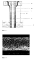
- a spinneret 1 as used in the present invention, which comprises a first pathway 4 through which a polymer solution of a at least one amphiphilic block copolymer in a solvent is provided, a second pathway 5 through which a sheath liquid comprising at least one precipitant pathway is provided, and a third pathway 6 through which a core gas stream is provided.
- the polymer solution is extruded through an annular die 10 via pathway 4 in direction of the arrow.
- a precipitant liquid is extruded through said annular die 10 via pathway 5 in direction of the arrow, and a gas stream is fed to an orifice within said die 10 via pathway 6 in direction of the arrow.
- the annular die 10 is designed such that the core gas stream 6 exits the die though at least one orifice encircled by a first annular die through which the polymer solution is fed to the annular die via pathway 4.
- the liquid sheath comprising at least one precipitant exits the spinneret through a second, outermost annular die which encircles the first annular die, and is fed to said second annular die via pathway 5.
- FIG. 2 there is shown a schematic cross-sectional representation of an annular die 10 and method according to the invention.
- the annular die 10 comprises a central orifice through which the gas stream 16 exits the spinneret, a first annular die encircling the central orifice through which the polymer solution 14 exits the spinneret, and a second, outermost annular die encircling the first annular portion through which the liquid sheath 15 exits the spinneret.
- the polymer solution 14 is extruded through said first annular die in spinneret 10 while simultaneously pressing a core gas stream 16 though a central orifice encircled by the first annular die and extruding a sheath liquid 15 comprising at least one precipitant from a second annular die encircling the first annular die into air, and subsequently into an aqueous precipitation bath 12.
- the gap 20 between spinneret and precipitation solution through which the extruded polymer solution passes surrounded by the sheath liquid and surrounding the core gas stream can be adjusted according to the requirements of the membrane.
- the spinning solution is finally precipitated in the precipitation bath 12 to form the hollow-fibre polymer membrane.
- the method according to the present invention comprises in particular pressing a core gas stream though one central orifice encircled by the first and second annular dies to form a single-bore hollow-fibre polymer membrane.
- the embodiments of Figs. 1 and 2 may be modified in that the core gas stream is pressed through at least two, preferably three to ten, more preferably five to seven orifices encircled by the first and second annular dies to form a multi-bore hollow-fibre polymer membrane.
- the parameters of the process such as temperature and flow rate of the polymer solution, temperature and flow rate of the liquid sheath, air flow and gap are selected such that a mechanically stable hollow fibre 14 is created as soon as it leaves the spinneret 10 in the direction of the precipitation bath 12 and a formation of a impermeable skin on the outside of the hollow fibre 14 is avoided.
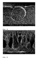
- Figs. 3 to 9 are SEM images of a membrane produced according to Example 1 of the present invention (produced from a polystyrene-b-poly-4-vinylpyridine copolymer which was dissolved in a DMF/THF mixture using the following process parameters: air flow: 1.21 mL/min; dope flow rate: 2.2 mL/min; water flow rate: 1 mL/min; air gap: 6 cm).
- Fig. 3 is a representation of the hollow-fibre polymer membrane
- Figs. 4 and 5 are representations of a cross-sectional cut through the hollow-fibre polymer membrane in different enlargements.
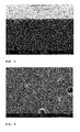
- Fig. 6 shows the cross section of hollow-fibre polymer membrane at the outer surface
- FIG. 7 shows the outer surface of the hollow-fibre polymer membrane in planar view.
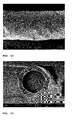
- Fig. 8 shows the cross section at the inner surface of the hollow-fibre polymer membrane, and
- Fig. 9 shows the inner surface of hollow-fibre polymer membrane in planar view.
- the scanning electron microscope (SEM) images in Figures 3 to 16 show a relatively narrow pore size distribution on the inner skin, which is caused by the microphase separation and the solvent-precipitant exchange.
- the outer skin shows elliptical pore structures, which were created due to the slowed phase inversion on the inside of the hollow fibre 14 and aligned parallel to the spinning direction due to the shearing in the gap. In certain cases, considerable hollow spaces occur here, which create a porosity, which is needed for the filtration.
- Polystyrene- block -poly(4-vinylpyridine) (PS-b-P4VP) block copolymer was dissolved in the mixtures of N,N -dimethyl formamide (DMF) and tetrahydrofuran (THF) at room temperature for about 24 hours under continuous mixing with a magnetic stirrer until the dope solution became homogeneous. Before spinning, the prepared polymer solutions remained at room temperature without stirring for 12 hours to remove the shear effect of stirring and fine air bubbles entrapped in the solutions.
- DMF N,N -dimethyl formamide
- THF tetrahydrofuran
- PS-b-P4VP hollow fiber membranes were spun at different air gap distances, which were varied as follows: 6, 10, 15, and 20 cm.
- the spinneret comprised a combination of three concentric cylinders.
- the innermost cylinder had a diameter of 0.32 mm for bore fluid which was connected to air.
- the syringe of the dope solution was connected to the middle cylinder of the spinneret; this central annulus for dope flow had a radius of 0.34 mm.
- the polymer solution passed through a hoop of water having a radius 0.15 mm with air inside. During spinning, all flow rates were controlled by high precision pumps.
- the circlet flow of water around the polymer solution works as an external coagulant and, air in contact with the inner side of polymer solution initiates the microphase separation of the block copolymer by evaporating THF from block copolymer solution.
- the nascent fibers were extruded from the tip of the spinneret through a certain length of the gap distance before emerging into the precipitation bath which contained pure water. In the gap steamy ambience was given to the fiber for its fast precipitation and continuous processing. The variation in the gap distance between the spinneret and precipitation bath let the volatile solvent evaporate from the inner side of nascent fibers at different times. THereafter, the hollow fibers entered the immersion bath with their falling velocity without applying external drawing force. The hollow fibers were kept in the water container for 24 hours at room temperature to complete removal of the residual solvent (DMF and THF), and then finally dried in air for one day. To assure complete solvent evaporation, the fibers were put under vacuum at room temperature for more than 24 hours.
- DMF and THF residual solvent
Abstract
Description
- The present invention relates to a hollow-fibre membrane having a novel structure and to a production method therefor. In particular, the hollow-fibre membrane according to the present invention is characterized in that it has an isoporous inner skin and a porous outer skin. The production method for the hollow-fibre membrane according to the present invention includes a novel dry/wet spinning method.
- The invention further relates to the use of the hollow-fibre polymer membrane according to the present invention for filtration, such as in particular for microfiltration, ultrafiltration, nanofiltration and/or reverse osmosis, in particular for ultrafiltration.
- Membrane separation technology using a separation membrane having a hollow-fibre structure has been applied to water purification and sewage and wastewater processes. In accordance with the material used for its production, membranes useful in particular for water treatment can be classified into the following categories: polymer membranes, ceramic membranes, and metal membranes. Such membranes are used for microfiltration (MF), ultrafiltration (UF), nanofiltration (NF), and reverse osmosis (RO). Ultra-filtration membranes allow the ion material to be permeated, but remove low-molecular polymer particles or bacteria and viruses, and may vary according to the requirements of use. They usually have a pore size in a range of from 0.01 to 0.1 µm. Ultra-filtration membranes having such characteristics have a wide application range, but are particularly interesting for pretreatment of process water or ultrapure water, reuse, sewage and wastewater treatment and water purification.
- Polymeric porous sheet membranes are generally prepared by phase separation of polymer solutions. Phase separation can be induced by cooling or by the presence of precipitant. Precipitant induced phase separation (NIPS) is taught for example in
U.S. Patents 3,615,024 ;5,066,401 ; and6,024,872 . Thermally induced phase separation (TIPS) is taught for example inU.S. Patents 4,702,836 and7,247,238 . - A large number of microporous membranes with a variety of morphologies have been prepared from various polymers, including poly(vinylidene fluoride) (PVDF), polyethylene, polypropylene, poly(methyl methacrylate), polystyrene and poly(ethylene-co-vinyl alcohol), by TIPS. In particular, PVDF, which is a semi-crystalline polymer, has wide applications in manufacture of microfiltration (MF) and ultrafiltration (UF) membranes because of its excellent properties such as good mechanical strength, stability against aggressive chemicals and good thermal stability. PVDF microfiltration membranes prepared by the TIPS method have been commercially applied in drinking-water production and wastewater treatment.
- Published
U.S. Patent Application 2009 173 694 A1 discloses a method for producing polymeric membranes having an isoporous separation-active structure by the NIPS method. The method includes dissolving one or more polymers, at least one of which is a block copolymer, in a liquid which includes a solvent, to produce a casting solution. The casting solution is formed into film, and the film is immersed into a precipitation bath which contains at least one precipitant for the block copolymer so that the film forms a membrane. The membrane is used for filtering a fluid that contains colloidal particles or proteins, and/or for ultrafiltration or nanofiltration, by flowing the fluid through the membrane. - Polymeric hollow-fibre membranes are desirable over sheet membranes because they have comparatively higher surface area per volume of the module and higher packaging densities. Polymeric hollow-fibre membranes are commonly produced by "melt spinning", where a thermoplastic polymer is molten and extruded through a spinneret into air and subsequently cooled, by "dry spinning", where a polymer is dissolved in an appropriate solvent and extruded through a spinneret into air and subsequently cooled, by "dry/wet spinning", where a polymer is dissolved in an appropriate solvent and extruded into air and a subsequent precipitant, usually water, and "wet spinning", where a polymer is dissolved and extruded directly into a precipitant. Common to each of these methods is the use of a spinneret, which comprises an annular die through which a polymer solution is extruded. Spinnerets are e.g. described in published European Patent Application
0 277 619 A2 or inU.S. Patent 4,385,017 , which are both incorporated herein by reference. - As the polymer exits the spinneret, it solidifies into a membrane through a process known as "phase inversion". Phase inversion can be induced by reducing the temperature of the solution, immersing the polymer solution into a non-solvent, exposing the polymer to a vapor of non-solvent or evaporating the solvent in atmospheric air or at high temperature. The properties of the membrane - such as average pore diameter and membrane thickness - can be finely tuned by changing the dimensions of the spinneret, temperature and composition of "dope" (polymer) and "bore" (solvent) solutions, length of air gap (for dry/wet spinning), temperature and composition of the precipitant, as well as the speed at which produced fibre is collected by a motorized spool. Extrusion of the polymer and solvent through the spinneret can be accomplished either through the use of gas-extrusion or a metered pump. Some of the polymers most commonly used for fabricating hollow-fibre membranes include cellulose acetate, polysulfone, polyethersulfone, and polyvinylidene flouride.
- Polymeric hollow-fibre membranes have a more or less large statistical variance of the distribution of the pore size. In addition to a low selectivity, hollow-fibre membranes having too large pore sizes tend to fouling, whereby the large pores are blocked. In order to reduce the tendency of fouling, isoporous membranes have been developed.
- Published Canadian Patent Application
2,886,437 A1 , which is incorporated herein by reference, discloses a method for producing a hollow-fibre polymer membrane having an isoporous outer skin, a porous inner skin and a sponge-like inner structure. The method described inCA 2,886,437 A1 comprises providing a polymer solution of at least one amphiphilic block copolymer in an appropriate solvent, extruding the polymer solution through an annular die in a spinneret while simultaneously extruding an aqueous core liquid from an orifice encircled by the annular die into air and subsequently into a precipitation bath to precipitate the spinning solution to form the hollow fibre. The method described inCA 2,886,437 A1 produces excellent hollow-fibre polymer membrane having an isoporous outer skin. - However, in many cases an opposite filtration direction is desirable. This is because of ease during filtration, handling and maintenance. For example, cleaning of membranes with isoporous inner skin by backwashing or forward aeration will be easier, and the overall fouling and clogging by bacteria may thereby be reduced in comparison to hollow-fibre polymer membranes having an isoporous outer skin. However, production of hollow-fibre polymer membranes having an isoporous inner skin and a porous outer skin remains a challenge.
- It is therefore an object of the present invention to provide such hollow-fibre polymer membranes having an isoporous inner skin, as well as a method for the production thereof.
- The above objects are solved by a method for producing a hollow-fibre polymer membrane having an isoporous inner skin, and a porous outer skin, comprising providing a polymer solution of at least one amphiphilic block copolymer in a suitable solvent; extruding the polymer solution (dope) through a first annular die in a spinneret while simultaneously pressing a core gas stream, preferably with constant pressure, through at least one orifice encircled by the first die and extruding a sheath liquid comprising at least one precipitant from a second annular die encircling the first die into air, and subsequently into an aqueous precipitation bath, thereby providing a gap between spinneret and precipitation solution through which the extruded polymer solution passes surrounded by the sheath liquid and surrounding the core gas stream, and finally precipitating the spinning solution in the precipitation bath to form the hollow-fibre polymer membrane.
- Preferably the first and second dies have an annular die exit. However, alternative geometries such as elliptical die exits or a profiled die exits are also conceivable.
- According to one embodiment, the method according to the present invention comprises in particular pressing a core gas stream though one orifice encircled by the first and second annular dies to form a single-bore hollow-fibre polymer membrane. According to another embodiment the method according to the present invention comprises pressing a core gas stream through at least two, preferably three to ten, more preferably five to seven orifices encircled by the first and second annular dies to form a multi-bore hollow-fibre polymer membrane.
- The membranes according to the present invention are self-supporting and have an isoporous inner skin, a porous outer skin, and a sponge-like inner structure. Formation of cylindrical pore structures on the inner skin is effected at the gap between spinneret and precipitation solution though which the extruded polymer solution passes surrounded by the sheath liquid and surrounding the core gas stream before entering the precipitation solution in that volatile solvents evaporate from the polymer solution into the core gas stream at the inner skin of the forming membrane.
- The at least one amphiphilic block copolymer used in the polymer solution for producing the hollow-fibre membranes according to the present invention preferably comprises two or more different polymer blocks such as blocks A, B; or A, B, C; or A, B, C, D forming block copolymers of the configuration A-B, A-B-A, A-B-C, A-B-C-B-A, A-B-C-D, A-B-C-D-C-B-A or multiblock copolymers based on the aforementioned configurations. Multiblock copolymers comprise structures of the base configurations that repeat multiple times. The polymer blocks are preferably selected from the group consisting of polystyrene, poly(α-methylstyrene), poly(para-methylstyrene), poly(t-butyl styrene), poly(trimethylsilylstyrene), poly-4-vinylpyridine, poly-2-vinylpyridine, poly(vinyl cyclohexane), polybutadiene, polyisoprene, poly(ethylene-stat-butylene), poly(ethylene-alt-propylene), polysiloxane, polyalkylene oxide such as polyethylene oxide, poly-ε-caprolactone, polylactic acid, poly(alkyl methacrylate) such as poly(methyl methacrylate), polymethacrylic acid, poly(alkyl acrylate) such as poly(methyl acrylate), polyacrylic acid, poly(hydroxyethyl methacrylate), polyacrylamide, poly-N-alkylacrylamide, polysulfone, polyaniline, polypyrrole, polytriazole, polyvinylimidazole, polytetrazole, polyethylene diamine, polyvinyl alcohol, polyvinylpyrrolidone, polyoxadiazole, polyvinylsulfonic acid, polyvinyl phosphonic acid or polymers.
- Preferred amphiphilic block copolymers for use in the present invention are selected from polystyrene-b-poly-4-vinylpyridine copolymers, poly(α-methylstyrene)-b-poly-4-vinylpyridine copolymers, poly(para-methylstyrene)-b-poly-4-vinylpyridine copolymers, poly(t-butylstyrene)-b-poly-4-vinylpyridine copolymers, poly(trimethylsilylstyrene)-b-poly-4-vinylpyridine copolymers, polystyrene-b-poly-2-vinylpyridine copolymers, poly(α-methylstyrene)-b-poly-2-vinylpyridine copolymers, poly(para-methylstyrene)-b-poly-2-vinylpyridine copolymers, poly(t-butylstyrene)-b-poly-2-vinylpyridine copolymers, poly(trimethylsilylstyrene)-b-poly-2-vinylpyridine copolymers, polystyrene-b-polybutadiene copolymers, poly(α-methylstyrene)-b-polybutadiene copolymers, poly(para-methylstyrene)-b-polybutadiene copolymers, poly(t-butylstyrene)-b-polybutadiene copolymers, poly(trimethylsilylstyrene)-b-polybutadiene copolymers, polystyrene-b-polyisoprene copolymers, poly(α-methylstyrene)-b-polyisoprene copolymers, poly(para-methylstyrene)-b-polyisoprene copolymers, poly(t-butylstyrene)-b-polyisoprene copolymers, poly(trimethylsilyl-styrene)-b-polyisoprene copolymers, polystyrene-b-poly(ethylene-stat-butylene) copolymers, poly(α-methylstyrene)-b-poly(ethylene-stat-butylene) copolymers, poly(para-methylstyrene)-b-poly(ethylene-stat-butylene) copolymers, poly(t-butylstyrene)-b-poly(ethylene-stat-butylene) copolymers, poly(trimethylsilylstyrene)-b-poly(ethylene-stat-butylene) copolymers, polystyrene-b-(ethylene-alt-propylene) copolymers, poly(α-methylstyrene)-b-(ethylene-alt-propylene) copolymers, poly(para-methylstyrene)-b-(ethylene-alt-propylene) copolymers, poly(t-butylstyrene)-b-(ethylene-alt-propylene) copolymers, poly(trimethylsilylstyrene)-b-(ethylene-alt-propylene) copolymers, polystyrene-b-polysiloxane copolymers, poly(α-methylstyrene)-b-polysiloxane copolymers, poly(para-methylstyrene)-b-polysiloxane copolymers, poly(t-butylstyrene)-b-polysiloxane copolymers, poly(trimethylsilylstyrene)-b-polysiloxane copolymers, polystyrene-b-polyalkylene oxide copolymers, poly(α-methylstyrene)-b-polyalkylene oxide copolymers, poly(paramethylstyrene)-b-polyalkylene oxide copolymers, poly(t-butylstyrene)-b-polyalkylene oxide copolymers, poly(trimethylsilylstyrene)-b-polyalkylene oxide copolymers, polystyrene-b-poly-ε-caprolactone copolymers, poly(α-methylstyrene)-b-poly-ε-caprolactone copolymers, poly(para-methylstyrene)-b-poly-ε-caprolactone copolymers, poly(t-butylstyrene)-b-poly-ε-caprolactone copolymers, poly(trimethylsilylstyrene)-b-poly-ε-caprolactone copolymers, polystyrene-b-poly(methyl methacrylate) copolymers, poly(α-methylstyrene)-b-poly(methyl methacrylate) copolymers, poly(para-methylstyrene)-b-poly(methyl methacrylate) copolymers, poly(t-butylstyrene)-b-poly(methyl methacrylate) copolymers, poly(trimethylsilylstyrene)-b-poly (methyl methacrylate) copolymers, polystyrene-b-poly(methyl acrylate) copolymers, poly(α-methylstyrene)-b-poly(methyl acrylate) copolymers, poly(para-methylstyrene)-b-poly(methyl acrylate) copolymers, poly(t-butylstyrene)-b-poly(methyl acrylate) copolymers, poly(trimethylsilylstyrene)-b-poly(methyl acrylate), polystyrene-b-poly(hydroxyethyl methacrylate) copolymers, poly(α-methylstyrene)-b-poly(hydroxyethyl methacrylate) copolymers, poly(paramethylstyrene)-b-poly(hydroxyethyl methacrylate) copolymers, poly(t-butylstyrene)-b-poly(hydroxyethyl methacrylate) copolymers, poly(trimethylsilylstyrene)-b-poly(hydroxyethyl methacrylate) copolymers, polystyrene-b-polyacrylamide copolymers, poly(α-methylstyrene)-b-polyacrylamide copolymers, poly(paramethylstyrene)-b-polyacrylamide copolymers, poly(t-butylstyrene)-b-polyacrylamide copolymers, poly(trimethylsilylstyrene)-b-polyacrylamide copolymers, polystyrene-b-polyvinyl alcohol copolymers, poly(α-methylstyrene)-b-polyvinyl alcohol copolymers, poly(para-methylstyrene)-b-polyvinyl alcohol copolymers, poly(t-butylstyrene)-b-polyvinyl alcohol copolymers, poly(trimethylsilylstyrene)-b-polyvinyl alcohol copolymers, polystyrene-b-polyvinylpyrrolidone copolymers, poly(α-methylstyrene)-b-polyvinylpyrrolidone copolymers, poly(para-methylstyrene)-b-polyvinylpyrrolidone copolymers, poly(t-butylstyrene)-b-polyvinylpyrrolidone copolymers, poly(trimethylsilylstyrene)-b-polyvinylpyrrolidone copolymers, polystyrene-b-poly-vinylcyclohexane copolymers, polystyrene-b-poly-vinylcyclohexane copolymers, polystyrene-b-poly-vinylcyclohexane copolymers, polystyrene-b-poly-vinylcyclohexane copolymers, poly(trimethylsilylstyrene)-b-poly-vinylcyclohexane copolymers and the like.
- The block copolymers and the polymer blocks used according to the present invention preferably have a polydispersity of less than 2.5, more preferably of less than 2.2, more preferably of less than 2.0. The polymer lengths of the at least two polymer blocks of the amphiphilic block copolymers are preferably selected with respect to each other so that a self-organization in the solvent leads to the formation of a spherical, cylindrical or co-continuous, in particular gyroidal, micelle structures or microphase structures in the solvent, in particular a length ratio between approximately 2:1 and approximately 10:1, in particular between approx. 3:1 and 6:1. These length ratios of the majority components to the minority components of the block copolymers lead to the desired micelle structure, i.e. to the inclusion of individual spherical micelles of the minority components in the bulk of the majority components or to cylindrical or continuous, for example gyroidal, micelle structures, in which the minority components form the cylinders or respectively gyroidal filaments or respectively branchings in the bulk of the majority components.
- The block copolymers preferably have a molecular weight between 50 kg/mol and 200 kg/mol, in particular between 75 kg/mol and 150 kg/mol. In this range, the pore size can be adjusted in a particular fine manner through selection of the molecular weight. The polymer preferably makes up a percentage by weight between 10 wt.% and 50 wt.%, more preferably between 15 wt.% and 35 wt.%, and most preferably between 25 wt.% and 30 wt.% of the polymer solution.
- Several solvents are suitable for preparing the polymer solution. Preferred solvents include diethyl ether, dimethylformamide, dimethylacetamide, N-methylpyrrolidone, dimethylsulfoxide, acetonitrile, dioxane, acetone, and/or tetrahydrofurane. Preferably, a solvent mixture is applied which is preferably selected such that different polymer blocks of the amphiphilic block copolymers are soluble up to different degrees and such that solvents are volatile to different degrees. The use of a solvent mixture supports the solidification of the self-organization and microphase formation on the inner surface of the hollow fibre before immersion in the precipitation bath. A preferred solvent mixture includes dimethylformamide and tetrahydrofurane.
- According to a further preferred embodiment of the present invention, the polymer solution comprises at least one metal salt. Preferably the metal is selected from an element of the second main group of the periodic system of elements, such as Mg, Ca or Sr or from non-toxic transition metals such as Fe. More preferably, the salt is an organic salt of Mg, Ca or Sr, most preferably magnesium acetate. The metals of the second main group of the periodic system are biocompatible making them preferred for hollow-fibre membranes with biological applications. The supporting effect of the salt in the phase separation can probably be explained in that the metal salt leads to the formation of partially charged polyelectrolytic micelle cores, which positively impact the precipitant-induced phase separation.
- According to a still further preferred embodiment, the polymer solution comprises at least one carbohydrate, multifunctional phenol and/or multifunctional organic acid. Preferred carbohydrates include saccharose, D(+)-glucose, D(-)-fructose and/or cyclodextrin, in particular α-cyclodextrin. Carbohydrates as used in the present invention lead to a stabilization of the isoporous separation-active surface during the phase inversion. The supporting effect of the at least one carbohydrate in phase separation can probably be explained in that the carbohydrates form hydrogen bonds with the hydrophilic block of the block copolymers.
- The sheath liquid extruded from the second annular die comprises at least one precipitant such as water and/or an alcohol, such as methanol or ethanol. According to the present invention, a precipitant with reduced precipitation activity is preferably used as a sheath liquid for producing the outer surface of the hollow-fibre membrane since tests have shown that a conventional precipitant such as water, a mixture of polyethylene glycol (PEG) and water, or a mixture of glycerol and water do not provide a sufficiently coarsened porous outer skin. The use of a precipitant with reduced precipitation activity causes the surface formation to progress with slower kinetics than for a conventional precipitant and, thus, causes that larger pores can form in a more regular manner. Therefore, the liquid sheath preferably consists of a mixture of at least one precipitant, most preferably water, and at least one solvent for the at least one amphiphilic block copolymer. Preferably the precipitant comprises water, methanol, ethanol or a mixture of two or more thereof. Most preferably, precipitant comprises water, methanol, ethanol or a mixture of two or more thereof in admixture with any one or more of diethyl ether, dimethylformamide, dimethylacetamide, N-methylpyrrolidone, dimethylsulfoxide, acetonitrile, acetone, and/or tetrahydrofurane. Most preferably the precipitant comprises a mixture of water and dimethylformamide. Preferably the ratio of water, methanol, ethanol or a mixture of two or more thereof on the one hand, and diethyl ether, dimethylformamide, dimethylacetamide, N-methylpyrrolidone, dimethylsulfoxide, acetonitrile, acetone, and/or tetrahydrofurane is from 75:25 to 40:60, more preferably about 50:50. Most preferably the precipitant comprises or is comprised of a mixture of water and dimethylformamide in a ratio of about 50:50.
- The liquid in the precipitation bath preferably also comprises water, methanol, ethanol or a mixture of two or more thereof in admixture with any one or more of diethyl ethern more preferably in admixture with at least one pore forming material such as polyethylene glycol (PEG) or glycerol. Most preferably the precipitation bath comprises or is comprised of a mixture of water and glycerol.
- The core gas may be selected from any gas which does not react with the polymer of the membrane. Preferably, the core gas is selected from air, nitrogen and/or a noble gas such as argon or helium, most preferably from air or nitrogen.
- In accordance with a preferred embodiment of the method according to the present invention, the polymer solution is extruded through the first annular orifice in the spinneret with a pressure of 1 to 50 kPa gauge, in particular between 5 and 25 kPa gauge, thereby forming a regular hollow-fibre membrane. The gap between the spinneret and the precipitation bath preferably has a length of between 1 cm and 50 cm, in particular between 10 cm and 25 cm.
- The object underlying the invention is also solved by a hollow-fibre polymer membrane having an isoporous inner skin and a porous outer skin. The isopores of the separation-active inner surface preferably have a ratio of the maximum pore diameter to the minimum pore diameter of less than 3.
- Furthermore, the present invention provides a filtration module, in particular a microfiltration module, an ultrafiltration module, or a nanofiltration module, comprising at least one of the hollow-fibre polymer membranes according to the present invention.
- Further characteristics of the invention will become apparent from the description of embodiments according to the invention together with the claims and the included drawings.
- The invention is now described below in an exemplary manner, without restricting the general intent of the invention, based on exemplary embodiments with reference to the figures appended hereto, wherein:
-
Fig. 1 is a schematic cross-sectional representation of a spinneret as used in the present invention. -
Fig. 2 is a schematic cross-sectional illustration of the method for forming a hollow-fibre polymer membrane having an isoporous inner skin and a porous outer skin according to the present invention. -
Figs. 3 to 9 are SEM images of a membrane produced according to Example 1 of the present invention (produced from a polystyrene-b-poly-4-vinylpyridine copolymer which was dissolved in a DMF/THF mixture using the following process parameters: air flow: 1.21 mL/min; dope flow rate: 2.2 mL/min; water flow rate: 1 mL/min; air gap: 6 cm).Fig. 3 is a representation of the hollow-fibre polymer membrane, andFigs. 4 and 5 are representations of a cross-sectional cut through the hollow-fibre polymer membrane in different enlargements.Fig. 6 shows the cross section of hollow-fibre polymer membrane at the outer surface, andFig. 7 shows the outer surface of the hollow-fibre polymer membrane in planar view.Fig. 8 shows the cross section at the inner surface of the hollow-fibre polymer membrane, andFig. 9 shows the inner surface of hollow-fibre polymer membrane in planar view. -
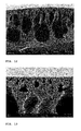
Figs. 10 to 16 are SEM images of a membrane produced according to Example 1 of the present invention (produced from a polystyrene-b-poly-4-vinylpyridine copolymer which was dissolved in a DMF/THF mixture using the following process parameters: air flow: 1.74 mL/min; dope flow rate: 2.2 mL/min; water flow rate: 1 mL/min; air gap: 6 cm).Fig. 10 is a representation of the hollow-fibre polymer membrane, andFigs. 11 and12 are representations of a cross-sectional cut through the hollow-fibre polymer membrane in different enlargements.Fig. 13 shows the cross section of hollow-fibre polymer membrane at the outer surface, andFig. 14 shows the outer surface of the hollow-fibre polymer membrane in planar view.Fig. 15 shows the cross section at the inner surface of the hollow-fibre polymer membrane, andFig. 16 shows the inner surface of hollow-fibre polymer membrane in planar view. - With reference to
Fig. 1 , there is shown a schematic cross-sectional representation of aspinneret 1 as used in the present invention, which comprises afirst pathway 4 through which a polymer solution of a at least one amphiphilic block copolymer in a solvent is provided, asecond pathway 5 through which a sheath liquid comprising at least one precipitant pathway is provided, and athird pathway 6 through which a core gas stream is provided. The polymer solution is extruded through anannular die 10 viapathway 4 in direction of the arrow. Simultaneously, a precipitant liquid is extruded through said annular die 10 viapathway 5 in direction of the arrow, and a gas stream is fed to an orifice within saiddie 10 viapathway 6 in direction of the arrow. The annular die 10 is designed such that thecore gas stream 6 exits the die though at least one orifice encircled by a first annular die through which the polymer solution is fed to the annular die viapathway 4. The liquid sheath comprising at least one precipitant exits the spinneret through a second, outermost annular die which encircles the first annular die, and is fed to said second annular die viapathway 5. - More details of the construction of the dies will become apparent from
Fig. 2 . - With reference to
Fig. 2 there is shown a schematic cross-sectional representation of anannular die 10 and method according to the invention. The annular die 10 comprises a central orifice through which thegas stream 16 exits the spinneret, a first annular die encircling the central orifice through which thepolymer solution 14 exits the spinneret, and a second, outermost annular die encircling the first annular portion through which theliquid sheath 15 exits the spinneret. Thepolymer solution 14 is extruded through said first annular die inspinneret 10 while simultaneously pressing acore gas stream 16 though a central orifice encircled by the first annular die and extruding asheath liquid 15 comprising at least one precipitant from a second annular die encircling the first annular die into air, and subsequently into anaqueous precipitation bath 12. Thegap 20 between spinneret and precipitation solution through which the extruded polymer solution passes surrounded by the sheath liquid and surrounding the core gas stream can be adjusted according to the requirements of the membrane. The spinning solution is finally precipitated in theprecipitation bath 12 to form the hollow-fibre polymer membrane. - According to the embodiments of
Figs. 1 and2 , the method according to the present invention comprises in particular pressing a core gas stream though one central orifice encircled by the first and second annular dies to form a single-bore hollow-fibre polymer membrane. Alternatively the embodiments ofFigs. 1 and2 may be modified in that the core gas stream is pressed through at least two, preferably three to ten, more preferably five to seven orifices encircled by the first and second annular dies to form a multi-bore hollow-fibre polymer membrane. - The parameters of the process such as temperature and flow rate of the polymer solution, temperature and flow rate of the liquid sheath, air flow and gap are selected such that a mechanically stable
hollow fibre 14 is created as soon as it leaves thespinneret 10 in the direction of theprecipitation bath 12 and a formation of a impermeable skin on the outside of thehollow fibre 14 is avoided. -
Figs. 3 to 9 are SEM images of a membrane produced according to Example 1 of the present invention (produced from a polystyrene-b-poly-4-vinylpyridine copolymer which was dissolved in a DMF/THF mixture using the following process parameters: air flow: 1.21 mL/min; dope flow rate: 2.2 mL/min; water flow rate: 1 mL/min; air gap: 6 cm).Fig. 3 is a representation of the hollow-fibre polymer membrane, andFigs. 4 and 5 are representations of a cross-sectional cut through the hollow-fibre polymer membrane in different enlargements.Fig. 6 shows the cross section of hollow-fibre polymer membrane at the outer surface, andFig. 7 shows the outer surface of the hollow-fibre polymer membrane in planar view.Fig. 8 shows the cross section at the inner surface of the hollow-fibre polymer membrane, andFig. 9 shows the inner surface of hollow-fibre polymer membrane in planar view. - The scanning electron microscope (SEM) images in
Figures 3 to 16 show a relatively narrow pore size distribution on the inner skin, which is caused by the microphase separation and the solvent-precipitant exchange. In contrast, the outer skin shows elliptical pore structures, which were created due to the slowed phase inversion on the inside of thehollow fibre 14 and aligned parallel to the spinning direction due to the shearing in the gap. In certain cases, considerable hollow spaces occur here, which create a porosity, which is needed for the filtration. - Polystyrene-block-poly(4-vinylpyridine) (PS-b-P4VP) block copolymer was dissolved in the mixtures of N,N-dimethyl formamide (DMF) and tetrahydrofuran (THF) at room temperature for about 24 hours under continuous mixing with a magnetic stirrer until the dope solution became homogeneous. Before spinning, the prepared polymer solutions remained at room temperature without stirring for 12 hours to remove the shear effect of stirring and fine air bubbles entrapped in the solutions.
- PS-b-P4VP hollow fiber membranes were spun at different air gap distances, which were varied as follows: 6, 10, 15, and 20 cm. The spinneret comprised a combination of three concentric cylinders. The innermost cylinder had a diameter of 0.32 mm for bore fluid which was connected to air. The syringe of the dope solution was connected to the middle cylinder of the spinneret; this central annulus for dope flow had a radius of 0.34 mm. After coming out from the spinneret to the precipitation bath, the polymer solution passed through a hoop of water having a radius 0.15 mm with air inside. During spinning, all flow rates were controlled by high precision pumps. The circlet flow of water around the polymer solution works as an external coagulant and, air in contact with the inner side of polymer solution initiates the microphase separation of the block copolymer by evaporating THF from block copolymer solution.
- The nascent fibers were extruded from the tip of the spinneret through a certain length of the gap distance before emerging into the precipitation bath which contained pure water. In the gap steamy ambiance was given to the fiber for its fast precipitation and continuous processing. The variation in the gap distance between the spinneret and precipitation bath let the volatile solvent evaporate from the inner side of nascent fibers at different times. THereafter, the hollow fibers entered the immersion bath with their falling velocity without applying external drawing force. The hollow fibers were kept in the water container for 24 hours at room temperature to complete removal of the residual solvent (DMF and THF), and then finally dried in air for one day. To assure complete solvent evaporation, the fibers were put under vacuum at room temperature for more than 24 hours.
- SEM images of
Samples Figs. 3 to 16 discussed above, where the inner surface shows a good porosity and the outer surface shows a low porosity. The porosity on outer surface was be increased by using mixture of solvent and water, for example water/DMF (50/50).
Claims (15)
- A method for producing a hollow-fibre polymer membrane (14) having an isoporous inner skin, and a porous outer skin, comprising providing a polymer solution (4) of at least one amphiphilic block copolymer in a solvent; extruding the polymer solution (dope) through a first annular die in a spinneret (1) while simultaneously pressing a core gas stream (6, 16) through at least one orifice encircled by the first die and extruding a sheath liquid (5, 15) comprising at least one precipitant from a second die encircling the first annular die into air, and subsequently into an aqueous precipitation bath (12), thereby providing a gap (20) between spinneret (1, 10) and precipitation solution through which the extruded polymer solution (14) passes surrounded by the sheath liquid (15) and surrounding the core gas stream (16), and finally precipitating the spinning solution in the precipitation bath (12) to form the hollow-fibre polymer membrane (14).
- The method according to claim 1, wherein comprising pressing a core gas stream (6, 16) through one single, central orifice encircled by the first and second annular dies to form a single-bore hollow-fibre polymer membrane.
- The method according claim 1, comprising pressing a core gas stream (6, 16) through two to ten orifices encircled by the first and second annular dies to form a multi-bore hollow-fibre polymer membrane.
- The method according to any of the previous claims, wherein the amphiphilic block copolymer is selected from polystyrene-b-poly-4-vinylpyridine copolymers, poly(α-methylstyrene)-b-poly-4-vinylpyridine copolymers, poly(para-methylstyrene)-b-poly-4-vinylpyridine copolymers, poly(t-butylstyrene)-b-poly-4-vinylpyridine copolymers, poly(trimethylsilylstyrene)-b-poly-4-vinylpyridine copolymers, polystyrene-b-poly-2-vinylpyridine copolymers, poly(α-methylstyrene)-b-poly-2-vinylpyridine copolymers, poly(para-methylstyrene)-b-poly-2-vinylpyridine copolymers, poly(t-butylstyrene)-b-poly-2-vinylpyridine copolymers, poly(trimethylsilylstyrene)-b-poly-2-vinylpyridine copolymers, polystyrene-b-polybutadiene copolymers, poly(α-methylstyrene)-b-polybutadiene copolymers, poly-(para-methylstyrene)-b-polybutadiene copolymers, poly(t-butylstyrene)-b-polybutadiene copolymers, poly(trimethylsilylstyrene)-b-polybutadiene copolymers, polystyrene-b-polyisoprene copolymers, poly(α-methylstyrene)-b-polyisoprene copolymers, poly(para-methylstyrene)-b-polyisoprene copolymers, poly(t-butylstyrene)-b-polyisoprene copolymers, poly(trimethylsilyl-styrene)-b-polyisoprene copolymers, polystyrene-b- poly(ethylene-stat-butylene) copolymers, poly(α-methylstyrene)-b-poly(ethylene-stat-butylene) copolymers, poly(para-methylstyrene)-b-poly(ethylene-statbutylene) copolymers, poly(t-butylstyrene)-b-poly(ethylene-stat-butylene) copolymers, poly(trimethylsilylstyrene)-b-poly(ethylene-stat-butylene) copolymers, polystyrene-b-(ethylene-alt-propylene) copolymers, poly(α-methylstyrene)-b-(ethylene-alt-propylene) copolymers, poly(para-methylstyrene)-b-(ethylene-alt-propylene) copolymers, poly(t-butylstyrene)-b-(ethylene-alt-propylene) copolymers, poly(trimethylsilylstyrene)-b-(ethylene-altpropylene) copolymers, polystyrene-b- polysiloxane copolymers, poly(α-methylstyrene)-b-polysiloxane copolymers, poly(para-methylstyrene)-b-polysiloxane copolymers, poly(t-butylstyrene)-b-polysiloxane copolymers, poly(trimethylsilylstyrene)-b-polysiloxane copolymers, polystyrene-b-polyalkylene oxide copolymers, poly(α-methylstyrene)-b-polyalkylene oxide copolymers, poly(paramethylstyrene)-b-polyalkylene oxide copolymers, poly(t-butylstyrene)-b-polyalkylene oxide copolymers, poly(trimethyl-silylstyrene)-b-polyalkylene oxide copolymers, polystyrene-b- poly-ε-caprolactone copolymers, poly(α-methylstyrene)-b-poly-ε-caprolactone copolymers, poly(para-methylstyrene)-b-poly-ε-caprolactone copolymers, poly(t-butylstyrene)-b-poly-ε-caprolactone copolymers, poly(trimethylsilylstyrene)-b-poly-ε-caprolactone copolymers, polystyrene-b-poly(methyl methacrylate) copolymers, poly(α-methylstyrene)-b-poly(methyl methacrylate) copolymers, poly(para-methylstyrene)-b-poly(methyl methacrylate) copolymers, poly(t-butylstyrene)-b-poly(methyl methacrylate) copolymers, poly(trimethylsilylstyrene)-b-poly (methyl methacrylate) copolymers, polystyrene-b-poly(methyl acrylate) copolymers, poly(α-methylstyrene)-b-poly(methyl acrylate) copolymers, poly(paramethylstyrene)-b- poly(methyl acrylate) copolymers, poly(t-butylstyrene)-b- poly(methyl acrylate) copolymers, poly(trimethylsilylstyrene)-b-poly(methyl acrylate), polystyrene-b-poly(hydroxyethyl methacrylate) copolymers, poly(α-methylstyrene)-b- poly(hydroxyethyl methacrylate) copolymers, poly(para-methylstyrene)-b-poly(hydroxyethyl methacrylate) copolymers, poly(t-butylstyrene)-b-poly(hydroxyethyl methacrylate) copolymers, poly(trimethylsilylstyrene)-b-poly(hydroxyethyl methacrylate) copolymers, polystyrene-b-polyacrylamide copolymers, poly(α-methylstyrene)-b-polyacrylamide copolymers, poly(para-methylstyrene)-b-polyacrylamide copolymers, poly(t-butylstyrene)-b-polyacrylamide copolymers, poly(trimethyl-silylstyrene)-b-polyacrylamide copolymers, polystyrene-b-polyvinyl alcohol copolymers, poly(α-methylstyrene)-b-polyvinyl alcohol copolymers, poly(paramethylstyrene)-b-polyvinyl alcohol copolymers, poly(t-butylstyrene)-b-polyvinyl alcohol copolymers, poly(trimethylsilylstyrene)-b-polyvinyl alcohol copolymers, polystyrene-b-polyvinylpyrrolidone copolymers, poly(α-methylstyrene)-b-polyvinylpyrrolidone copolymers, poly(para-methylstyrene)-b-polyvinylpyrrolidone copolymers, poly(t-butylstyrene)-b-polyvinylpyrrolidone copolymers, and poly(trimethylsilylstyrene)-b-polyvinylpyrrolidone copolymers polystyrene-b-poly-vinylcyclohexane copolymers, polystyrene-b-poly-vinylcyclohexane copolymers, polystyrene-b-poly-vinylcyclohexane copolymers, polystyrene-b-poly-vinylcyclohexane copolymers, poly(trimethylsilylstyrene)-b-polyvinyl-cyclohexane copolymers and the like.
- The method according to any of the previous claims, wherein the amphiphilic block copolymer has a polydispersity of less than 2.5
- The method according to any of the previous claims, wherein the solvent for the polymer is selected from diethyl ether, dimethylformamide, dimethylacetamide, N-methylpyrrolidone, dimethyl-sulfoxide, acetonitrile, dioxane, acetone, and/or tetrahydrofurane.
- The method according to any of the previous claims, wherein the polymer solution further comprises an organic metal salt, wherein the metal is selected from an element of the second main group of the periodic system.
- The method according to any of the previous claims, wherein the polymer solution further comprises at least one carbohydrate selected from a multifunctional phenol, a multifunctional organic acid, saccharose, D(+)-glucose, D(-)-fructose and/or cyclodextrin, in particular α-cyclodextrin.
- The method according to any of the previous claims, wherein the sheath liquid extruded from said second annular die comprises water and/or an alcohol, and further comprises a solvent present in the polymer solution.
- The method according to any of the previous claims, wherein the liquid sheath extruded from said further comprises at least one pore forming material selected from polyethylene glycol (PEG) and glycerol.
- The method according to any of the previous claims, wherein the core gas is selected from air, nitrogen and a noble gas or from a mixture thereof.
- The method according to any of the previous claims, wherein the polymer solution is extruded through the first annular orifice in the spinneret with a pressure of 1 to 50 kPa.gauge thereby forming a regular hollow-fibre membrane.
- The method according to any of the previous claims, wherein the gap between the spinneret and the precipitation bath has a length of between 1 cm and 100 cm.
- A polymeric hollow-fibre membrane having an isoporous inner skin and a porous outer skin.
- Use of a hollow-fibre membrane according to claim 14 or produced according to any of claims 1 to 13 for filtration, reverse-osmosis or dialysis.
Priority Applications (1)
| Application Number | Priority Date | Filing Date | Title |
|---|---|---|---|
| EP15186835.3A EP3147024A1 (en) | 2015-09-25 | 2015-09-25 | Hollow-fibre polymer membrane |
Applications Claiming Priority (1)
| Application Number | Priority Date | Filing Date | Title |
|---|---|---|---|
| EP15186835.3A EP3147024A1 (en) | 2015-09-25 | 2015-09-25 | Hollow-fibre polymer membrane |
Publications (1)
| Publication Number | Publication Date |
|---|---|
| EP3147024A1 true EP3147024A1 (en) | 2017-03-29 |
Family
ID=54199091
Family Applications (1)
| Application Number | Title | Priority Date | Filing Date |
|---|---|---|---|
| EP15186835.3A Withdrawn EP3147024A1 (en) | 2015-09-25 | 2015-09-25 | Hollow-fibre polymer membrane |
Country Status (1)
| Country | Link |
|---|---|
| EP (1) | EP3147024A1 (en) |
Cited By (9)
| Publication number | Priority date | Publication date | Assignee | Title |
|---|---|---|---|---|
| EP3434357A1 (en) | 2017-07-27 | 2019-01-30 | Helmholtz-Zentrum Geesthacht Zentrum für Material- und Küstenforschung GmbH | Method for preparing isoporous hollow fiber composite membranes |
| CN110833768A (en) * | 2018-08-15 | 2020-02-25 | 华东理工大学 | Double-layer polyamide solvent-resistant nanofiltration membrane containing β -CD @ ZIF-8 nanoparticles and preparation method thereof |
| CN111097297A (en) * | 2019-12-30 | 2020-05-05 | 江西师范大学 | Boron-doped microporous silicon dioxide membrane and preparation method and application thereof |
| EP3772370A1 (en) | 2019-08-05 | 2021-02-10 | Helmholtz-Zentrum Geesthacht Zentrum für Material- und Küstenforschung GmbH | Method of producing a polymeric membrane |
| CN113457463A (en) * | 2021-07-29 | 2021-10-01 | 湖南欧威爱特新材料科技有限公司 | Biodegradable inorganic-organic composite membrane and preparation method thereof |
| CN113766960A (en) * | 2019-05-27 | 2021-12-07 | 联合利华知识产权控股有限公司 | Fibers comprising organosilanes for liquid purification |
| EP3943181A1 (en) * | 2020-07-22 | 2022-01-26 | Gambro Lundia AB | Spinning beam |
| EP3970839A1 (en) * | 2020-09-21 | 2022-03-23 | Gambro Lundia AB | Spinneret |
| US11466115B2 (en) | 2018-06-01 | 2022-10-11 | 3M Innovative Properties Company | Porous membranes including triblock copolymers |
Citations (10)
| Publication number | Priority date | Publication date | Assignee | Title |
|---|---|---|---|---|
| US3615024A (en) | 1968-08-26 | 1971-10-26 | Amicon Corp | High flow membrane |
| US4385017A (en) | 1977-06-30 | 1983-05-24 | Nippon Zeon Co., Ltd. | Method of manufacturing hollow fiber |
| EP0193725A2 (en) * | 1985-03-07 | 1986-09-10 | Gambro Dialysatoren GmbH & Co. KG | Process for spinning hollow fiber membranes |
| US4702836A (en) | 1984-12-27 | 1987-10-27 | Asahi Kasei Kogyo Kabushiki Kaisha | Porous fluorine resin membrane and process for preparing the same |
| EP0277619A2 (en) | 1987-02-05 | 1988-08-10 | Air Products And Chemicals, Inc. | Spinneret for making hollow fibers having different wall thicknesses |
| US5066401A (en) | 1989-07-13 | 1991-11-19 | Akzo N.V. | Flat or capillary membrane based on a homogeneous mixture of polyvinylidene fluoride and a second polymer which can be rendered hydrophilic by chemical reaction |
| US6024872A (en) | 1997-07-01 | 2000-02-15 | Zenon Evironmental Inc. | Method of making a dope comprising hydrophilized PVDF and α-alumina, and a membrane made therefrom |
| US7247238B2 (en) | 2002-02-12 | 2007-07-24 | Siemens Water Technologies Corp. | Poly(ethylene chlorotrifluoroethylene) membranes |
| US20090173694A1 (en) | 2006-09-22 | 2009-07-09 | Gkss-Forschungzentrum Geesthacht Gmbh | Isoporous membrane and method of production thereof |
| CA2886437A1 (en) | 2012-11-22 | 2014-05-30 | Helmholtz-Zentrum Geesthacht Zentrum fur Material-und Kustenforschung GmbH | Method for producing an integral-asymmetric hollow-fibre polymer membrane consisting of an amphiphilic block copolymer, the hollow-fibre membrane obtained and the use thereof |
-
2015
- 2015-09-25 EP EP15186835.3A patent/EP3147024A1/en not_active Withdrawn
Patent Citations (10)
| Publication number | Priority date | Publication date | Assignee | Title |
|---|---|---|---|---|
| US3615024A (en) | 1968-08-26 | 1971-10-26 | Amicon Corp | High flow membrane |
| US4385017A (en) | 1977-06-30 | 1983-05-24 | Nippon Zeon Co., Ltd. | Method of manufacturing hollow fiber |
| US4702836A (en) | 1984-12-27 | 1987-10-27 | Asahi Kasei Kogyo Kabushiki Kaisha | Porous fluorine resin membrane and process for preparing the same |
| EP0193725A2 (en) * | 1985-03-07 | 1986-09-10 | Gambro Dialysatoren GmbH & Co. KG | Process for spinning hollow fiber membranes |
| EP0277619A2 (en) | 1987-02-05 | 1988-08-10 | Air Products And Chemicals, Inc. | Spinneret for making hollow fibers having different wall thicknesses |
| US5066401A (en) | 1989-07-13 | 1991-11-19 | Akzo N.V. | Flat or capillary membrane based on a homogeneous mixture of polyvinylidene fluoride and a second polymer which can be rendered hydrophilic by chemical reaction |
| US6024872A (en) | 1997-07-01 | 2000-02-15 | Zenon Evironmental Inc. | Method of making a dope comprising hydrophilized PVDF and α-alumina, and a membrane made therefrom |
| US7247238B2 (en) | 2002-02-12 | 2007-07-24 | Siemens Water Technologies Corp. | Poly(ethylene chlorotrifluoroethylene) membranes |
| US20090173694A1 (en) | 2006-09-22 | 2009-07-09 | Gkss-Forschungzentrum Geesthacht Gmbh | Isoporous membrane and method of production thereof |
| CA2886437A1 (en) | 2012-11-22 | 2014-05-30 | Helmholtz-Zentrum Geesthacht Zentrum fur Material-und Kustenforschung GmbH | Method for producing an integral-asymmetric hollow-fibre polymer membrane consisting of an amphiphilic block copolymer, the hollow-fibre membrane obtained and the use thereof |
Non-Patent Citations (4)
| Title |
|---|
| ALBRECHT W ET AL: "Preparation of highly asymmetric hollow fiber membranes from poly(ether imide) by a modified dry-wet phase inversion technique using a triple spinneret", JOURNAL OF MEMBRANE SCIENCE, ELSEVIER BV, NL, vol. 262, no. 1-2, 1 October 2005 (2005-10-01), pages 69 - 80, XP027869424, ISSN: 0376-7388, [retrieved on 20051001] * |
| LIU Z ET AL: "The hollow fiber ultrafiltration membrane with inner skin and its application", DESALINATION, ELSEVIER, AMSTERDAM, NL, vol. 233, no. 1-3, 15 December 2008 (2008-12-15), pages 55 - 63, XP025712437, ISSN: 0011-9164, [retrieved on 20081029], DOI: 10.1016/J.DESAL.2007.09.027 * |
| ROLAND HILKE ET AL: "Block copolymer/homopolymer dual-layer hollow fiber membranes", JOURNAL OF MEMBRANE SCIENCE, vol. 472, 1 December 2014 (2014-12-01), NL, pages 39 - 44, XP055259401, ISSN: 0376-7388, DOI: 10.1016/j.memsci.2014.08.031 * |
| T. HE ET AL: "Preparation of porous hollow fiber membranes with a triple-orifice spinneret", JOURNAL OF APPLIED POLYMER SCIENCE, vol. 87, no. 13, 28 March 2003 (2003-03-28), US, pages 2151 - 2157, XP055259135, ISSN: 0021-8995, DOI: 10.1002/app.11591 * |
Cited By (16)
| Publication number | Priority date | Publication date | Assignee | Title |
|---|---|---|---|---|
| WO2019020278A1 (en) | 2017-07-27 | 2019-01-31 | Helmholtz-Zentrum Geesthacht Zentrum für Material- und Küstenforschung GmbH | Method for preparing isoporous hollow fiber composite membranes |
| CN110913978A (en) * | 2017-07-27 | 2020-03-24 | 亥姆霍兹材料研究与海岸研究盖斯特哈赫特中心 | Method for preparing uniform-hole hollow fiber composite membrane |
| EP3434357A1 (en) | 2017-07-27 | 2019-01-30 | Helmholtz-Zentrum Geesthacht Zentrum für Material- und Küstenforschung GmbH | Method for preparing isoporous hollow fiber composite membranes |
| US11185828B2 (en) | 2017-07-27 | 2021-11-30 | Helmholtz-Zentrum Hereon Gmbh | Method for preparing isoporous hollow fiber composite membranes |
| US11466115B2 (en) | 2018-06-01 | 2022-10-11 | 3M Innovative Properties Company | Porous membranes including triblock copolymers |
| CN110833768B (en) * | 2018-08-15 | 2021-12-28 | 华东理工大学 | Double-layer polyamide solvent-resistant nanofiltration membrane containing beta-CD @ ZIF-8 nanoparticles and preparation method thereof |
| CN110833768A (en) * | 2018-08-15 | 2020-02-25 | 华东理工大学 | Double-layer polyamide solvent-resistant nanofiltration membrane containing β -CD @ ZIF-8 nanoparticles and preparation method thereof |
| CN113766960A (en) * | 2019-05-27 | 2021-12-07 | 联合利华知识产权控股有限公司 | Fibers comprising organosilanes for liquid purification |
| EP3772370A1 (en) | 2019-08-05 | 2021-02-10 | Helmholtz-Zentrum Geesthacht Zentrum für Material- und Küstenforschung GmbH | Method of producing a polymeric membrane |
| WO2021023500A1 (en) | 2019-08-05 | 2021-02-11 | Helmholtz-Zentrum Geesthacht Zentrum für Material- und Küstenforschung GmbH | Method of producing a polymeric membrane |
| CN111097297A (en) * | 2019-12-30 | 2020-05-05 | 江西师范大学 | Boron-doped microporous silicon dioxide membrane and preparation method and application thereof |
| EP3943181A1 (en) * | 2020-07-22 | 2022-01-26 | Gambro Lundia AB | Spinning beam |
| WO2022018116A1 (en) | 2020-07-22 | 2022-01-27 | Gambro Lundia Ab | Spinning beam |
| EP3970839A1 (en) * | 2020-09-21 | 2022-03-23 | Gambro Lundia AB | Spinneret |
| WO2022058611A1 (en) | 2020-09-21 | 2022-03-24 | Gambro Lundia Ab | Spinneret |
| CN113457463A (en) * | 2021-07-29 | 2021-10-01 | 湖南欧威爱特新材料科技有限公司 | Biodegradable inorganic-organic composite membrane and preparation method thereof |
Similar Documents
| Publication | Publication Date | Title |
|---|---|---|
| EP3147024A1 (en) | Hollow-fibre polymer membrane | |
| DK2922620T3 (en) | Process for the preparation of integral asymmetric hollow fiber polymer membrane consisting of amphiphilic block copolymer, the hollow fiber membrane obtained and use thereof | |
| US8424688B2 (en) | Preparation of high performance ultra filtration hollow fiber membrane | |
| WO1981000969A1 (en) | Polyvinylidene fluoride resin hollow filament microfilter and process for producing same | |
| JP2006088148A (en) | Hollow fiber membrane having excellent water permeability | |
| WO1997022405A1 (en) | Hollow fiber type filtration membrane | |
| JP7014714B2 (en) | Porous membrane and method for producing porous membrane | |
| WO2010029908A1 (en) | Hollow-fiber membrane and process for production of hollow-fiber membrane | |
| US11185828B2 (en) | Method for preparing isoporous hollow fiber composite membranes | |
| JPH0569571B2 (en) | ||
| JP2005144412A (en) | Polyketone hollow fiber membrane and manufacturing method of the same | |
| JP3760838B2 (en) | Method for producing hollow fiber membrane and hollow fiber membrane | |
| JP3317975B2 (en) | Polyacrylonitrile hollow fiber filtration membrane | |
| JP2688564B2 (en) | Cellulose acetate hollow fiber separation membrane | |
| KR101347042B1 (en) | Manufacturing method of asymmetric pvdf membrane and asymmetric pvdf membrane with improved properties manufactured thereby | |
| JPWO2016182015A1 (en) | Porous hollow fiber membrane and method for producing the same | |
| KR102426676B1 (en) | Microfiber-based Membranes and Method for Preparing the Same | |
| KR20130040622A (en) | The preparation method of hollow fiber membrane with high permeation using hydrophilized polyvinylidenefluoride for water treatment | |
| JP7095072B2 (en) | Hollow fiber membrane and method for manufacturing hollow fiber membrane | |
| JPH10337456A (en) | Membrane forming stock solution | |
| JPH0722690B2 (en) | Aromatic polysulfone hollow fiber membrane and method for producing the same | |
| JPH11244675A (en) | Production of membrane | |
| KR20150079196A (en) | High flow-rate hollow fiber type ultrafiltration membrane and method for manufacturing thereof |
Legal Events
| Date | Code | Title | Description |
|---|---|---|---|
| PUAI | Public reference made under article 153(3) epc to a published international application that has entered the european phase |
Free format text: ORIGINAL CODE: 0009012 |
|
| STAA | Information on the status of an ep patent application or granted ep patent |
Free format text: STATUS: THE APPLICATION HAS BEEN PUBLISHED |
|
| AK | Designated contracting states |
Kind code of ref document: A1 Designated state(s): AL AT BE BG CH CY CZ DE DK EE ES FI FR GB GR HR HU IE IS IT LI LT LU LV MC MK MT NL NO PL PT RO RS SE SI SK SM TR |
|
| AX | Request for extension of the european patent |
Extension state: BA ME |
|
| STAA | Information on the status of an ep patent application or granted ep patent |
Free format text: STATUS: REQUEST FOR EXAMINATION WAS MADE |
|
| 17P | Request for examination filed |
Effective date: 20170907 |
|
| RBV | Designated contracting states (corrected) |
Designated state(s): AL AT BE BG CH CY CZ DE DK EE ES FI FR GB GR HR HU IE IS IT LI LT LU LV MC MK MT NL NO PL PT RO RS SE SI SK SM TR |
|
| RIN1 | Information on inventor provided before grant (corrected) |
Inventor name: ABETZ, VOLKER Inventor name: HANDGE, ULRICH A. Inventor name: SANKHALA, KIRTI Inventor name: KOLL, JOACHIM |
|
| STAA | Information on the status of an ep patent application or granted ep patent |
Free format text: STATUS: EXAMINATION IS IN PROGRESS |
|
| 17Q | First examination report despatched |
Effective date: 20190313 |
|
| STAA | Information on the status of an ep patent application or granted ep patent |
Free format text: STATUS: EXAMINATION IS IN PROGRESS |
|
| RAP3 | Party data changed (applicant data changed or rights of an application transferred) |
Owner name: HELMHOLTZ-ZENTRUM HEREON GMBH |
|
| GRAP | Despatch of communication of intention to grant a patent |
Free format text: ORIGINAL CODE: EPIDOSNIGR1 |
|
| STAA | Information on the status of an ep patent application or granted ep patent |
Free format text: STATUS: GRANT OF PATENT IS INTENDED |
|
| INTG | Intention to grant announced |
Effective date: 20221108 |
|
| STAA | Information on the status of an ep patent application or granted ep patent |
Free format text: STATUS: THE APPLICATION IS DEEMED TO BE WITHDRAWN |
|
| 18D | Application deemed to be withdrawn |
Effective date: 20230321 |