EP3148028A1 - Device for protecting an electric power supply device and electrical energy supply device with such a protective device - Google Patents
Device for protecting an electric power supply device and electrical energy supply device with such a protective device Download PDFInfo
- Publication number
- EP3148028A1 EP3148028A1 EP16187767.5A EP16187767A EP3148028A1 EP 3148028 A1 EP3148028 A1 EP 3148028A1 EP 16187767 A EP16187767 A EP 16187767A EP 3148028 A1 EP3148028 A1 EP 3148028A1
- Authority
- EP
- European Patent Office
- Prior art keywords
- source
- load
- voltage
- protection
- stage
- Prior art date
- Legal status (The legal status is an assumption and is not a legal conclusion. Google has not performed a legal analysis and makes no representation as to the accuracy of the status listed.)
- Pending
Links
Images


Classifications
-
- H—ELECTRICITY
- H02—GENERATION; CONVERSION OR DISTRIBUTION OF ELECTRIC POWER
- H02H—EMERGENCY PROTECTIVE CIRCUIT ARRANGEMENTS
- H02H7/00—Emergency protective circuit arrangements specially adapted for specific types of electric machines or apparatus or for sectionalised protection of cable or line systems, and effecting automatic switching in the event of an undesired change from normal working conditions
- H02H7/26—Sectionalised protection of cable or line systems, e.g. for disconnecting a section on which a short-circuit, earth fault, or arc discharge has occured
- H02H7/261—Sectionalised protection of cable or line systems, e.g. for disconnecting a section on which a short-circuit, earth fault, or arc discharge has occured involving signal transmission between at least two stations
-
- H—ELECTRICITY
- H02—GENERATION; CONVERSION OR DISTRIBUTION OF ELECTRIC POWER
- H02H—EMERGENCY PROTECTIVE CIRCUIT ARRANGEMENTS
- H02H3/00—Emergency protective circuit arrangements for automatic disconnection directly responsive to an undesired change from normal electric working condition with or without subsequent reconnection ; integrated protection
- H02H3/02—Details
- H02H3/033—Details with several disconnections in a preferential order, e.g. following priority of the users, load repartition
-
- H—ELECTRICITY
- H02—GENERATION; CONVERSION OR DISTRIBUTION OF ELECTRIC POWER
- H02H—EMERGENCY PROTECTIVE CIRCUIT ARRANGEMENTS
- H02H3/00—Emergency protective circuit arrangements for automatic disconnection directly responsive to an undesired change from normal electric working condition with or without subsequent reconnection ; integrated protection
- H02H3/16—Emergency protective circuit arrangements for automatic disconnection directly responsive to an undesired change from normal electric working condition with or without subsequent reconnection ; integrated protection responsive to fault current to earth, frame or mass
-
- H—ELECTRICITY
- H02—GENERATION; CONVERSION OR DISTRIBUTION OF ELECTRIC POWER
- H02H—EMERGENCY PROTECTIVE CIRCUIT ARRANGEMENTS
- H02H3/00—Emergency protective circuit arrangements for automatic disconnection directly responsive to an undesired change from normal electric working condition with or without subsequent reconnection ; integrated protection
- H02H3/26—Emergency protective circuit arrangements for automatic disconnection directly responsive to an undesired change from normal electric working condition with or without subsequent reconnection ; integrated protection responsive to difference between voltages or between currents; responsive to phase angle between voltages or between currents
- H02H3/28—Emergency protective circuit arrangements for automatic disconnection directly responsive to an undesired change from normal electric working condition with or without subsequent reconnection ; integrated protection responsive to difference between voltages or between currents; responsive to phase angle between voltages or between currents involving comparison of the voltage or current values at two spaced portions of a single system, e.g. at opposite ends of one line, at input and output of apparatus
- H02H3/30—Emergency protective circuit arrangements for automatic disconnection directly responsive to an undesired change from normal electric working condition with or without subsequent reconnection ; integrated protection responsive to difference between voltages or between currents; responsive to phase angle between voltages or between currents involving comparison of the voltage or current values at two spaced portions of a single system, e.g. at opposite ends of one line, at input and output of apparatus using pilot wires or other signalling channel
-
- H—ELECTRICITY
- H02—GENERATION; CONVERSION OR DISTRIBUTION OF ELECTRIC POWER
- H02H—EMERGENCY PROTECTIVE CIRCUIT ARRANGEMENTS
- H02H1/00—Details of emergency protective circuit arrangements
- H02H1/0007—Details of emergency protective circuit arrangements concerning the detecting means
- H02H1/0015—Using arc detectors
-
- H—ELECTRICITY
- H02—GENERATION; CONVERSION OR DISTRIBUTION OF ELECTRIC POWER
- H02H—EMERGENCY PROTECTIVE CIRCUIT ARRANGEMENTS
- H02H1/00—Details of emergency protective circuit arrangements
- H02H1/06—Arrangements for supplying operative power
-
- H—ELECTRICITY
- H02—GENERATION; CONVERSION OR DISTRIBUTION OF ELECTRIC POWER
- H02H—EMERGENCY PROTECTIVE CIRCUIT ARRANGEMENTS
- H02H3/00—Emergency protective circuit arrangements for automatic disconnection directly responsive to an undesired change from normal electric working condition with or without subsequent reconnection ; integrated protection
- H02H3/08—Emergency protective circuit arrangements for automatic disconnection directly responsive to an undesired change from normal electric working condition with or without subsequent reconnection ; integrated protection responsive to excess current
-
- H—ELECTRICITY
- H02—GENERATION; CONVERSION OR DISTRIBUTION OF ELECTRIC POWER
- H02H—EMERGENCY PROTECTIVE CIRCUIT ARRANGEMENTS
- H02H7/00—Emergency protective circuit arrangements specially adapted for specific types of electric machines or apparatus or for sectionalised protection of cable or line systems, and effecting automatic switching in the event of an undesired change from normal working conditions
- H02H7/06—Emergency protective circuit arrangements specially adapted for specific types of electric machines or apparatus or for sectionalised protection of cable or line systems, and effecting automatic switching in the event of an undesired change from normal working conditions for dynamo-electric generators; for synchronous capacitors
Definitions
- the invention relates to a protective device for an electrical power supply device.
- the invention further relates to an electrical power supply device with such a protective device.
- At least one first overload switch to which a first command and control unit is assigned, is arranged on a first hierarchical level.
- One or more other circuit breakers each comprising a respective second electronic unit, are arranged on one or more additional hierarchical levels hierarchically following the first hierarchical level, and arranged in cascade with one another.
- the first overload switch comprises at least one electronic semiconductor shutdown device.
- the first command and control unit is configured to cause the electronic solid-state shutdown means to drive a current flowing through this electronic solid-state shutdown means at least for a predetermined one, in response to an occurrence of an electrical failure in a grid area of the electrical power grid Limit duration.
- an intervention command is sent to the circuit breakers on the lower hierarchical levels, which is to cause intervention of that circuit breaker which is located next to the network area of all circuit breakers that have detected the electrical fault in which the electrical fault has occurred.
- This system and method seeks to provide an improved solution for selective intervention in response to detection of an electrical fault in the electrical power grid.
- Selective intervention or selectivity is understood to be the ability to separate only relatively limited network areas close to the location of the electrical fault from an electrical energy supply source.
- Such a capacity of coordinated and limited action is supposed to be the cause of the electrical fault Ineffectiveness limited only to the really vulnerable network areas and so at the same time the operating condition of the rest of the electrical energy supply network can be obtained.
- the invention has the object to provide a protective device for an electrical power supply device with the addition of a protection of an electrical energy supply network and in particular only relatively limited network areas in addition effective protection of the electrical power grid feeding electrical energy source - short: energy source - for energy sources low overcurrent capability is achieved.
- the energy source has the task of supplying electrical energy via the energy transmission device to the at least one load.
- the electrical power supply device may be formed with one or more energy sources, from which the at least one load is fed, i. which together - depending on each other or independent - feed energy into the energy transfer device.
- the protective device according to the invention can be used with an energy source which has a low overflow capability.
- this energy source having a low overcurrent capability can be set up both for outputting an AC voltage and a DC voltage as a source voltage.
- Overcurrent capability is defined as the ability of the power source to supply a current in excess of a nominal current to which the power source is dimensioned and with which it is intended to operate. Overcurrent, deliver. Low in this context, the overcurrent capability is referred to, if it is not sufficient to trigger a conventional overcurrent protection device when it is designed for the rated current of the power source.
- Such a conventional overcurrent time protection switching device is particularly preferably formed by a conventional line fuse, in particular by a conventional circuit breaker.
- tripping occurs regularly in that a certain overcurrent, which corresponds to a predefinable multiple of a rated current permissible in a network string of the energy transmission device, ie, for example, in a line of a power supply network to be protected, flows over the duration of a predefinable time interval.
- this overcurrent for example, a magnitude of two to Three times the rated current and the time interval has a duration of a few second fractions.
- the energy transmission device is configured to transmit the electrical energy from the energy source or the energy sources via the at least one network strand to the at least one load.
- the energy transmission device is designed as a power supply network - in short: network - to supply the at least one load.
- a network strand is a branch of the network to which - via a load protection stage - at least one load is connected.
- the network may contain other components, e.g. other branches or sections.
- the at least one load can be supplied with the electrical energy from the at least one energy source via the network.
- the at least one energy source, the network and the at least one load are thus configured to supply electrical energy from the at least one energy source via the network to the at least one load.
- the load voltage is that electrical voltage which, during operation of the electrical power supply device, i. the protective device according to the invention, on the load, i. whose terminals, is measured.
- the current is also referred to in a network strand. This string current corresponds to the sum of all currents in all loads connected to this one network string.
- each of the load protection stages is formed with at least one measuring device for detecting a phase current and a load voltage and with a switching device for disconnecting the power line from the power source when the phase current exceeds a predeterminable limit.
- Each such measuring device and each such switching device are thus included as minimum equipment of each of the load protection stages, so that each load protection stage has at least one overcurrent protection for the associated strand and a load voltage measurement.
- the embodiment of the protective device according to the invention with at least one source protection stage for switching off the at least one energy source in the presence of under or overvoltage at the energy source allows selective protection of each of the at least one energy source independent of the protection of the energy transmission device or the at least one network strand and the at least one load by the at least one load protection stage.
- a voltage at the energy source ie a voltage delivered by the energy source - in short: source voltage - exceeds a predetermined upper threshold or falls below a predetermined lower threshold.
- source voltage - exceeds a predetermined upper threshold or falls below a predetermined lower threshold.
- At least one, preferably exactly one, source protection stage is provided for each energy source.
- This source protection stage is used to shut off the power source in the presence of under or over voltage at the power source and thus the individual protection of exactly this energy source by jointly disconnecting all fed from this energy source network strands of this energy source upon detection of under- or over-voltage at the power source.
- power lines may be gradually disconnected from the power source and thereby the power source may be relieved incrementally, preferably to an operating condition in which said over-load is eliminated.
- At least one, preferably exactly one, central control stage is provided for each energy source.
- a respective second switching device is provided for each of the at least one network string, in particular with a relay, which can be fed by the at least one source protection stage, in particular by the source protection stage of the energy source from which the relevant network string is fed. is controllable to connect the respective network strand with the power source or to disconnect the relevant network strand from the power source.
- the respective second switching device for each of the at least one network string is controlled by the at least one source protection stage, in particular by the source protection stage of the power source from which the at least one network string is fed to connect or disconnect the respective network string with or from the source of energy.
- the at least one source protection stage and / or the at least one central control stage with the second switching device or the second switching devices are combined in an assembly, e.g. taken together in a kind of control box or distribution box.
- a signal transmission device for connecting at least the at least one central control stage and at least one of the one or more load protection stages to each other for transmitting at least one strand current detected by the measuring device of the load protection stage or load protection stages and / or one of the measuring device Load protection stage or load protection stages detected load voltage to the at least one central control stage.
- a trained with a data bus signal transmission device is provided, wherein such a data bus is advantageously formed according to known designs and standards.
- a very simple, efficient and rapid transmission of data comprising the measured values of the at least one detected phase current and / or the at least one detected load voltage, and vice versa, a transmission of data and / or control commands from the at least one central control stage the load protection stage or load protection stages are made very simple, powerful and fast.
- a preferred embodiment of the protective device according to the invention is characterized in that the at least one central control stage and / or the at least one load protection stage, each with at least one signal processing device, in particular digital signal processing device, preferably with a microprocessor-based signal processing device, i. a programmable controller, are configured.
- the design of the at least one load protection stage with a digital signal processing device allows not only a preparation of the aforementioned measured values of the at least one detected phase current and / or the at least one detected load voltage in digital data, a variety of other control functions, the simple and flexible selectable in the at least one load protection stage can be trained.
- a further signal transmission device is provided, via which at least the at least one central control stage with further external signal processing devices, in particular with devices for logging operating states of the protective device and / or with devices for remote control and / or remote maintenance , is connected, wherein preferably the further signal transmission device is formed with a data bus.
- the further signal transmission device is designed with the data bus with which the signal transmission device is designed for connecting at least the at least one central control stage and at least one of the one or more load protection stages, ie both signal transmission means are combined in a single data bus, whereby a particularly simple and reliable Structure is achieved.
- the further, external signal processing devices are preferably also formed with at least one digital signal processing device, in particular a computer, for example a central computer.
- the aforementioned means for logging and / or remote control and / or remote maintenance can be made very simple and powerful.
- the operation of the power supply device, in particular the protective device used therein can be carried out in a very powerful, versatile and flexible manner.
- logging of the operating states also makes it very easy to fulfill requirements for recording an operating sequence of such a power supply device, for example in an aircraft.
- Another advantageous use of logging and / or remote maintenance is that a at least partially automated error detection is feasible including a - also at least partially automatic - delivery of an order of spare parts for the power supply device.
- connection and / or disconnection of the at least one of the loads with and from the energy source in dependence on at least the available power output of the energy source ie the switching on and / or off of at least one of the loads from the power source depending on their performance and capacity utilization can be used advantageously for a so-called "energy management", by which the efficiency of electrical systems, in particular energy supply facilities to be increased.
- loads can be disconnected from the power transmission device or switched on again.
- the measured values of the at least one detected phase current and / or the at least one detected load voltage may also be preferred be evaluated.
- the measured values of the at least one detected phase current and / or the at least one detected load voltage can also advantageously be evaluated to detect high-resistance shorts and / or insulation faults in the at least one network line.
- the predetermined line resistance of the at least one network string as well as the source voltage are used.
- the measured value of the load voltage must correspond to a setpoint of this load voltage determined according to Ohm's law of source voltage, line resistance and phase current. High-impedance shorts and / or insulation faults are noticeable via additional currents, which cause additional voltage drops in the affected network strand. Measured value and setpoint of the load voltage no longer match. So if there is a deviation, this is detected as a high-impedance short circuit and / or insulation fault.
- the recognition of a nominal state of changed impedances and / or of interruptions in at least one of the at least one network branch and / or in at least one other branch of the energy transmission device advantageously takes place in a comparable manner on the basis of the at least one predetermined line resistance of the at least one network branch and measured phase current and measured load voltage.
- the energy supply device described here is advantageously fed by at least one source voltage designed as a direct and / or alternating voltage, frequencies of this source voltage preferably being low in relation to operating and / or clock frequencies, as is the case with conventional signal processing devices, in particular digital ones Signal processing means, preferably with a microprocessor trained signal processing means used.
- This makes it possible to carry out with the inventively designed at least one central control stage and / or load protection stage very precise measurements of time profiles of at least one load voltage and the at least one string current. From the measured values obtained, it is possible to determine deviations of these temporal courses from predefinable target progressions.
- such deviations of the at least one phase current are recognized as a fault current, and this residual current is used as a trigger for disconnecting the network strand from the energy source with the aid of the switching device of the load protection stage of the affected network strand.
- Such a fault current detection is much more accurate and responds to fault currents significantly more sensitive than a conventional rms measurement of a fault current, so that a comparison with e.g. significantly increased precision and sensitivity in the detection of fault currents is achieved in conventional FI switches.
- the deviations, in particular fault currents via the signal transmission device, preferably the data bus to which at least one central control stage and / or to other, external signal processing means are reported.
- each source protection stage is followed by a DC voltage conversion device, in particular designed with a DC-DC converter, downstream for converting a voltage delivered by the source protection stage into a protective extra-low voltage for operating the at least one second switching device and / or the at least one central control stage.
- a DC voltage conversion device in particular designed with a DC-DC converter, downstream for converting a voltage delivered by the source protection stage into a protective extra-low voltage for operating the at least one second switching device and / or the at least one central control stage.
- the voltage delivered by the source protection stage in such a way that the voltage delivered by the source protection stage corresponds to the source voltage except for circuit-related voltage losses, then the voltage delivered by the source protection stage also exceeds said protective extra-low voltage.
- this is disadvantageous and undesirable for operating the at least one second switching device and / or the at least one central control stage, since e.g. constructed with semiconductor circuits of conventional design, in particular digital, signal processing facilities are operated with much lower supply and / or signal voltages.
- the at least one second switching device and / or the at least one central control stage is operated with a voltage exceeding the protective extra-low voltage, it becomes more difficult to check and / or maintain and / or repair the protective device according to the invention, because then it can no longer be operated under voltage or allowed. Operating with a safety extra-low voltage avoids these disadvantages.
- the at least one energy source is arranged to supply at least one DC voltage, by means of which the at least one load can be supplied with energy from the at least one energy source.
- the protective device according to the invention is particularly preferably designed and used.
- the invention is not limited to use with a power source adapted to provide at least a DC voltage, but rather a preferred embodiment of the protective device according to the invention is characterized in that the at least one power source is arranged to supply at least one AC voltage by which the at least one load of energy from the at least one energy source can be fed, and that preferably a rectifier stage is provided for feeding the at least one source protection stage of the at least one energy source.
- the protective device according to the invention can then be configured identically for the operation of both power supply devices operated with DC voltage and of power supply devices operated with AC voltage, whereby a universal application possibility with simplified and cheaper production is given. It is also possible to use it in energy supply devices which are designed for mixed operation in such a way that one part of the energy supply device is operated with alternating voltage, another part with direct voltage.
- the electrical power supply device thus has all the features and advantages that are listed and explained above for the protection device according to the invention.
- FIG. 1 a first embodiment of a protective device according to the invention is shown in block-schematic representation and designated by the reference numeral 100.
- the protective device 100 is used in an electric power supply device 101 assumed here by way of example in a simple embodiment.
- the energy supply device 101 comprises an energy source 102, in particular a low overcurrent energy source 102, such as an energy source 102 formed with at least one fuel cell or at least one photovoltaic element or the like.
- Such energy sources 102 have a current-voltage characteristic which is very steep declining characteristic load above a rated current shows, ie when increasing a current drawn from the power source 102 current beyond the rated current addition, the voltage at the power source 102, ie the source voltage UQ drops very sharply and is already at a low exceeding the rated current to zero.
- a characteristic value for a low overcurrent capability is, for example, a drop in the source voltage UQ to zero when the rated current of the power source 102 is exceeded by 20%.
- conventional energy sources such as electrical generators operated as electric generators, briefly a multiple of their rated current as overcurrent, so have a high overcurrent capability, so that these energy sources with high overcurrent capability can be hedged by conventional line fuses, especially conventional circuit breakers.
- a hedge eg with conventional household circuit breakers requires an overcurrent, for example, in the order of two to three times the rated current.
- the power supply device 101 further comprises a power transmission device 103 having a first, a second and a third power line 104, 105 and 106, respectively. At each of the power lines 104, 105 and 106, at least one load is connected; in the illustration of the example FIG. 1 there are three loads 107 each.
- the protection device 100 provided for this electrical energy supply device contains for each network strand 104, 105 and 106, respectively, a load protection stage, ie a first, second and third load protection stage 108, 109 or 110, via which the loads 107 are applied to the relevant network string 104, 105 or 110. 106 are connected.
- a measuring device is arranged for detecting a strand current fed by the energy source 102 into the relevant network strand 104, 105 or 106, ie, a first, second or third strand current IL1, IL2 or IL3.
- the measuring devices in each of the load protection stages 108, 109, 110 are furthermore designed to detect a first, second or third load voltage UL1, UL2 or UL3, ie the voltage which is applied to the loads 107 via the relevant load protection stage 108, 109 or 110 , which are connected to the respective network strand 104, 105 and 106, applied. Furthermore, a respective switching device is provided in each of the load protection stages 108, 109, 110, which serves for disconnecting the relevant network strand 104, 105 or 106 from the energy source 102 when the relevant phase current IL1, IL2 or IL3 exceeds a predefinable limit value. In this case, only a partial, on faulty network strings limited load shedding takes place.
- the measuring device and the switching device are described below.
- the protection device 100 includes a source protection stage 111, which is adapted to shut off the power source 102 at under or over voltage at the power source 102, ie, in the case where the source voltage UQ exceeds a first threshold below or a second threshold.
- a source protection stage 111 which is adapted to shut off the power source 102 at under or over voltage at the power source 102, ie, in the case where the source voltage UQ exceeds a first threshold below or a second threshold.
- the power supply device 101 after FIG. 1 all power lines 104, 105, 106 separated from the power source 102, so there is a complete load shedding.
- the protection device 100 includes a central control stage 112, which is configured for each of the network strands 104, 105 and 106 to compare the load voltage applied in this network strand 104, 105 and 106 respectively UL1, UL2 and UL3 with the source voltage UQ and those the line strands 104, 105, 106, in which between the load voltage UL1, UL2 and UL3 and the source voltage UQ a deviation of predetermined size occurs to separate selectively. In this case, in turn, only a partial, on faulty network strings limited load shedding takes place.
- the protective device 100 is formed with a respective second switching device 113, 114 and 115 for each of the network strands 104, 105 and 106, respectively.
- Each of the second switching devices 113, 114 and 115 each comprise a relay 116, 117 and 118, each with a relay coil 116S, 117S and 118S and a respective switching contact 116K, 117K and 118K.
- the relay coil 116S, 117S and 118S are connected on one side to an output terminal 203 of the source protection stage 111.
- this connection is implemented via a DC-DC converter 119, by means of which the source voltage UQ is converted into a protective extra-low voltage for operating the relays 116, 117 or 118 and the central control stage 112.
- the relay coil 116S, 117S or 118S is connected to ground 123 via a respective switch element 120, 121 or 122, which is likewise a component of the relevant second switching device 113, 114 or 115.
- the switch elements 120, 121 and 122 are controlled via control lines 124, 125 and 126 from the central control stage 112 and operated in this manner.
- each one of the switching contacts 116K, 117K and 118K is arranged in each one of the network strands 104, 105 and 106 for connecting or disconnecting the network strands 104, 105 and 106, respectively and thus the loads 107 connected thereto from the energy source 102.
- all network strings 104, 105 and 106 are switched on and off at the same time, ie jointly, by the source protection stage 111 via their output terminal 203, whereas from the central one Control stage 112 via the control lines 124, 125 and 126, the network strands 104, 105 and 106 selectively, ie individually, are switched on or off.
- each network strand 104, 105 and 106 there is a second switching device 113, 114 or 115 formed with a relay 116, 117 and 118, respectively, which is protected by the source protection stage 111 of the energy source 102 from which the relevant network strand 104, 105 or 106 can be fed, via whose output terminal 203 is controllable to connect the respective network strand 104, 105 and 106 with the power source 102 or for separating the relevant network strand 104, 105 and 106 from the power source 102 via the switching contacts 116K, 117K or 118K.
- a signal transmission device 127 is provided for connecting the central control stage 112 and the load protection stages 108, 109, 110 with each other.
- the signal transmission device 127 serves to transmit the phase currents IL1, IL2 or IL3 detected by the measuring device of the load protection stages 108, 109, 110, ie their measured values, and the load voltages UL1, UL2 or respectively detected by the measuring device of the load protection stages 108, 109, 110.
- the central control stage 112 and the load protection stages 108, 109, 110 are designed for processing and transmitting the measured values, each with a digital signal processing device, preferably with a microprocessor, ie a programmable control device , as explained in more detail below.
- a further signal transmission device 128 is provided, via which the central control stage 112 is connected to further external signal processing devices, in particular to devices for logging operating states of the protective device 100 and / or to devices for remote control and / or remote maintenance.
- the further, external signal processing devices are likewise designed with a digital signal processing device, in this case a central computer 129.
- the signal transmission device 127 and the further signal transmission device 128 are combined in a common data bus 130 which connects the load stages 108, 109, 110, the central control stage 112 and the central computer 129 with one another.
- the data bus 130 is designed according to known designs and standards.
- a third signal transmission device 131 is provided for transmitting a measured value of the source voltage UQ from the source protection stage 111 to the central control stage 112.
- the connection from the output terminal 203 of the source protection stage 111 to the central control stage 112 can then be exclusively from a power supply of the central control stage 112 from the energy source 102 serve via the source protection stage 111 and the DC-DC converter 119.
- the source protection stage 111, the central control stage 112, the second switching devices 113, 114, 115 and the DC-DC converter 119 are combined in an assembly, referred to herein as a switch box 132.
- the electric power supply device 101 in the in FIG. 1 is formed with a power source 102 adapted to output a source voltage UQ formed as a DC voltage.
- the energy source 102 may also be configured to output a source voltage UQ formed as an alternating voltage, or the source voltage UQ may comprise a superimposition of a DC voltage and an AC voltage.
- a rectifier stage is then to be inserted in the energy transmission device 103, specifically directly in front of an input terminal 201 of the source protection stage 111, if only the Protective device 100, in particular only the source protection stage 111, to be supplied with DC voltage.
- said rectifier stage can also be designed in such a way that both the protective device 100 and the respective loads 107 are supplied by it.
- the protective device 100 according to the invention can be operated both with DC voltage sources and with AC voltage sources.
- FIG. 2 is an exemplary embodiment of a source protection stage 111 for use in a protection device 100 according to the invention, in particular according to FIG FIG. 1 , reproduced in block diagram form.
- the source protection stage 111 has an input terminal 201 for connection to the power source 102 and an output terminal 203 that is generally configured to connect a load and to which a load such as the loads 107 can thus be connected.
- the central control stage 112 and the second switching devices 113, 114, 115 to the network branches 104, 105 and 106, respectively, but not the network lines 104, 105, 106 themselves to the output terminal 203, via the DC-DC converter 119 connected, as in FIG. 1 is shown.
- the input terminal 201 is for connecting to a positive pole of the power source 102
- the output terminal 203 is configured to connect to a corresponding positive input terminal of the DC / DC converter 119.
- a second input terminal and a second output terminal of the source protection stage 111 are formed by a common ground terminal 205 of the source protection stage 111 set up for connection to ground 123.
- the power source 102, the DC-DC converter 119, the central control stage 112 and the second switching devices 113, 114, 115 according to FIG. 1 are connected to ground 123; However, this is not completely drawn for clarity and simplicity.
- the source protection stage 111 together with the input connection 201 and the output connection 203 has only three connections. Via the input terminal 201 and the ground terminal 205, the source protection voltage UQ of the energy source 102 can be supplied to the source protection stage 111 as a measurement DC voltage.
- the source protection stage 111 includes an undervoltage monitor 206 for detecting whether the source voltage, i. the DC measurement voltage, UQ falls below a first threshold US1, and an overvoltage monitor 207 for detecting whether the DC measurement voltage UQ exceeds a second threshold US2.
- the undervoltage monitoring device 206 is for this purpose formed with a first threshold circuit 208, which comprises a first adder stage 209 and a first proportional stage 210.
- the DC measurement voltage UQ is compared with the first threshold US1. If the measured direct voltage UQ falls below the first threshold value US1, a first switch-off signal is emitted via the first proportional stage 210 with a first proportional factor K1.
- the overvoltage monitoring device 207 is formed with a second threshold circuit 211, which comprises a second adder stage 212 and a second proportional stage 213.
- the DC measurement voltage UQ is compared with the second threshold US2. If the measured direct voltage UQ exceeds the second threshold value US2, a second shutdown signal is output via the second proportional stage 213 with a second proportional factor K2.
- the source protection stage 111 further comprises a switching device 214 controlled by the undervoltage monitoring device 206 and the overvoltage monitoring device 207 for establishing an electrical connection between the energy source and the load if the measured DC voltage UQ corresponds to at least the first US1 and at most the second threshold US2.
- the switching device 214 is formed with a comparator arrangement 215, preferably a differential amplifier arrangement, and further comprises a load switching device 216 controllable by the comparator arrangement 215, which in turn controllable a controllable current source arrangement 217 and one of the current source arrangement 217 by supplying a control current via a control terminal 218 of the current source arrangement 217 , in particular electromagnetic, load switch 219, here a relay, includes.
- the relay 219 is formed with a relay coil S and a switching contact KA.
- the relay coil S is coupled to the current source arrangement 217, and a connection between the input terminal 201 and the output terminal 203 can be produced via the switch contact KA, which forms an electrical connection between the energy source 102 and the DC voltage converter 119 functioning as a load of the source protection stage 111.
- a fuse SI is in series with controllable current source arrangement 217 connected and serves to protect the relay coil S and to protect against errors in the source protection stage 111th
- the shutdown control signals then supplied by the threshold circuits 208, 211 to the switching device 214 when the DC measurement voltage UQ falls below the first threshold value US1 or exceeds the second threshold value US2, respectively, drive the comparator arrangement 215 into a second switching state; otherwise the comparator assembly 215 assumes a first switching state.
- the current source arrangement 217 is controlled by the comparator arrangement 215 such that the control current can be fed to the load switch 219 via the control terminal 218 in the first switching state of the comparator arrangement 215 and is interrupted in its second switching state.
- the relay coil S is thus supplied with current from the current source arrangement 217 and thus the electrical connection between the energy source 102 and the DC voltage converter 119 forming the load of the source protection stage 111 is established via the switching contact KA.
- the comparator 215 goes into the second switching state, the current through the relay coil S is turned off, and the electrical connection between the power source 102 and here the load of the source protection stage 111 forming DC-DC converter 119 is opened by opening the switch contact KA interrupted.
- the relay 219 requires only one switching contact KA.
- a second relay can be added, the relay coil is connected in series with the relay coil S and the switching contact with the switching contact KA is arranged in series. If one of the relays fails, in particular "sticks", the electrical connection between the energy source 102 and the here the load of the source protection stage 111 forming DC-DC converter 119 is still reliably interrupted by the second relay.
- the relays 116-118 have a turn-off time that is dependent on the timing of the voltage applied to their relay coils 116S-118S during turn-off by the source protection stage 111. However, this time course is dependent on a capacitance of a smoothing capacitor at the output of the DC-DC converter 119 and the load connected thereto, ie, the number of relays 116 to 118, in particular the number of those of the relays 116 to 118, the straight are turned on by the central control stage 112.
- a further switch contact KB of the load switch 219 is provided at the output of the DC-DC converter, which is actuated simultaneously with the switch contact KA and ensures a defined time profile of the voltage supplied to the relay coils 116S to 118S and thus the switch-off time.
- the undervoltage monitor 206, the overvoltage supervisor 207, and the switch 214 are exclusively composed of the source voltage outputable from the power source 102, i. the DC measurement voltage, UQ powered.
- this source protection level 111 can be used as a primary network protection.
- the source protection stage 111 further comprises a switch-on stage 220 to which a switch-on signal can be supplied by an external active connection, which is formed here by a push-button T which can be operated manually externally by a user.
- the switch-on signal here a switch-on pulse which can be triggered by the pushbutton T, converts the switching device 214 from a second control state, in which the electrical connection between the energy source and the load is interrupted, into a first control state, in which this electrical connection is established ,
- the first control state of the switching device 214 is synonymous with the control state, in which the switching device 214 is transferred by the comparator 215 in its first switching state
- the second control state of the switching device 214 is synonymous with the control state in which the switching device 214 through the comparator 215 is transferred in the second switching state.
- the DC measurement voltage UQ of the second adder 212 of the second threshold circuit 211 via the switch contact KA and thus only after establishing the electrical connection between the power source 102 and here the load of the source protection stage 111 forming DC voltage converter 119 is supplied.
- the measured direct voltage UQ at the second threshold value circuit 211 is therefore not yet present. It is therefore supplied on the one hand via the switching contact KA and on the other hand by the button T via a connection 221 a link stage 222 and supplied from this the second adder 212.
- This is the DC measurement voltage UQ is also available for turning on the source protection stage 111 at the overvoltage monitor 207.
- the switch-on stage 220 further comprises a pulse shaping stage 223, which forms a switching pulse of a time duration TE when the push-button T is closed.
- the switching pulse of the time period TE is fed via a third proportional stage 224 with a factor K3 to another link stage 225 and forms in this way in addition to the output signal of the comparator 215, the control current for the current source assembly 217th With this switching pulse for the time period TE during power-up Source protection stage 111, the current source assembly 217 switched to a higher current for the relay coil S to ensure a safe tightening of the relay 219. After the end of the switching pulse, the current source assembly 217 is switched to a lower current sufficient to hold the relay 219.
- the comparator arrangement ie the differential amplifier arrangement, 215 has a further input for a further, in particular externally supplied, control signal ES.
- the further control signal ES serves to control the control state of the switching device 214 via the switching state of the comparator arrangement 215.
- the further control signal ES is a further shutdown control signal, by means of which the comparator arrangement 215 can be controlled in the second switching state.
- This makes it possible for the source protection stage 111 to fulfill a further protective function, for example a switch-off in the event of overheating of a part of the energy supply device 101, when the further control signal is supplied by a temperature sensor.
- Other operating parameters ES representing other operating parameters are possible.
- the source protection stage 111 after FIG. 2 is simple and robust and allows a precise determined shutdown of the network strands 104, 105, 106 with the loads 107 from the power source 102 in case of failure.
- FIG. 3 shows in block schematic representation another, designated by the reference numeral 301 example of an electrical power supply device; this is formed with a second embodiment of a protective device according to the invention by the reference numeral 300.
- the energy supply device 301 again comprises the energy source 102 and an energy transfer device 303.
- the energy transfer device 303 is formed with one or more network strands; For the sake of simplicity, however, only one - first - network string 304 is shown.
- a load 107 is connected to this first network string 304;
- an illustration of a connection of a plurality of loads 107 has been dispensed with.
- a second switching device inserted with the second switching device 113 to the first power line 104 of the power transmission device 103 of the power supply device 101 according to FIG. 1 is identical.
- FIG. 1 are in the protective device 300 after FIG. 3 one or more load protection stages and a central control stage are provided, which are formed with simple analog circuits and accordingly can only perform simple functions.
- a load protection stage 308 is roughly schematically represented, which has a measuring device for detecting the phase current IL1 and the load voltage UL1 in the first network strand 304.
- This measuring device comprises a current measuring device 350 for detecting the phase current IL1 and a voltage measuring device 351 for detecting the load voltage UL1.
- a measured value of the phase current IL1 is supplied by the current measuring device 350 to a current comparator 352 shown here as a differential amplifier, to which, on the other hand, a predefinable limit value ILmax for the phase current IL1 is also supplied.
- the load protection stage 308 further includes a switching device 353 for disconnecting the first network string 304, ie the load 107, from the energy source 102 when the phase current IL1 in the first network string 304 exceeds the predefinable limit value ILmax. This is an exit the current comparator 352 in circuit operative connection, for example via a control line, connected to the switching device 353.
- the central control stage of the protection device 300 contains a voltage comparison device for each network string;
- a voltage comparator 354 is shown here, also shown as a differential amplifier.
- the voltage comparison device 354 is on the one hand a measured value of the load voltage UL1 via a signal transmission device 327, here designed as a simple analog signal line, and on the other hand the source voltage UQ or a measured value of the source voltage UQ supplied.
- An output of the voltage comparator 354 is connected to the control line 124 of the second switching device 113 to the first power line 304 for controlling the second switching device 113 in the FIG. 1 described way.
- the source protection stage 111, the central control stage 312, the second switching device 113 and the DC-DC converter 119 are combined in a module as a switch box or distribution box 332.
- the protective functions of the invention can be perceived in a very simple manner.
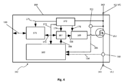
- FIG. 4 is a block diagram of an embodiment of a load protection stage for use in the first embodiment of the protection device 100 according to the invention after FIG. 1 shown here using the example of the first load protection stage 108 in the first network strand 104 of the energy transmission device 103.
- the first load protection stage 108 has a measuring device which comprises a current measuring device 150 and a voltage measuring device 151. Further, in the first load protection stage 108, a switching device 153 is provided, which is designed here as a field effect transistor.
- the current measuring device 150 and the switching device 153 are arranged in a current path for the phase current IL1 between a strand current input 160 and a strand current output 161 in series. In this case, the strand current input 160 is provided for connection to the energy source 102 and the strand current output 161 for connection to one or more loads 107.
- the load protection stage 108 is configured with a digital signal processing device 162, which is formed with a microprocessor 163.
- the microprocessor 163 is connected via a first measuring line 164 to the current measuring device 150 for supplying the measured values for the line current IL1 and via a second measuring line 165 to the voltage measuring device 151 for supplying the measured values for the load voltage UL1.
- the microprocessor 163 is set up to evaluate the phase current IL1 detected by the current measuring device 150 and / or the load voltage UL1 detected by the voltage measuring device 151, preferably its instantaneous values and / or their time profiles, and to recognize a fault current in the first network line 104.
- the microprocessor 163 is further configured to perform an overcurrent detection with overcurrent protection including a short circuit detection based on these measurements or based on a sequence of these measurements, as well as overvoltage detection with overvoltage protection. Furthermore, the microprocessor 163 is adapted to provide overheating protection by means of an integrated temperature sensor. Via a data output 166, data corresponding to at least measurement values of the detected phase current IL1 and / or the detected load voltage UL1 and further control commands for controlling at least the switching device 153 of the load protection stage 108 can be output by the microprocessor 163.
- the data output 166 of the microprocessor 163 is connected for this purpose to a control logic circuit 167, by which the data and / or control commands depending on their purpose via a control line 168 of a driver circuit 169 for controlling the switching device 153 and / or via a data line 170 to a data bus Interface circuit 171 can be routed.
- data and / or control commands from the data bus interface circuit 171 can be routed via the data line 170 to the control logic circuit 167 and supplied from there to the microprocessor 163 and / or the driver circuit 169.
- the data bus interface circuit 171 is also connected to the data bus 130 for exchanging data and / or control commands with the central control stage 112 and / or the central computer 129.
- the load protection circuit 108 comprises a power supply circuit 172 for deriving at least one supply voltage for the microprocessor 163, the control logic circuit 167, the data bus interface circuit 171 and the driver circuit 169 from the source voltage UQ.
- the load protection stage 108, the microprocessor 163, the control logic circuit 167 and the data bus interface circuit 171 are supplied via supply lines 173, 174 and 175 with a first DC supply voltage of 5 volts, and the driver circuit 169 is connected via a supply line 176 with a second DC supply voltage powered by 24 volts.
- monitoring of the string currents eg here the string current IL1 in the first network strand 304, on exceeding the predetermined limit ILmax can also be made a monitoring with safety curves, in particular as so-called I 2 t curves used in semiconductor power controls of aircraft on-board networks.
- safety curves can be realized very easily with a corresponding programming of the microprocessor 163.
- FIG. 5 shows in a rough schematic representation of an example of a detection of a high-impedance short circuit and / or insulation fault in a simple, third embodiment of a protective device 400 according to the invention, used in a third embodiment of an electrical power supply device 401st
- the electric power supply device 401 comprises a power transmission device 403 shown here with only a single network strand 404.
- the network strand 404 is fed from two independent energy sources 402A, 402B, from a first 402A of the energy sources via a first protective device 402A. and control stage 411A and from a second 402B of the power sources via a second protection and control stage 411B.
- the first protection and control stage 411A and the second protection and control stage 411B each comprise one source protection stage, one central control stage, one second switching device, and preferably one DC-DC converter according to the source protection stage 111 or the central control stage 112 or the second Switching device 113 and the DC-DC converter 119 according to the FIGS. 1 and 2 trained and electrically and preferably also spatially according to the FIGS. 1 and 2 connected to each other.
- a spatial extent X of the network strand 404 shown along the abscissa in the diagram of the figure part a) of FIG. 5 , is in a location XL via a load protection stage 108, which in its construction according to those FIGS.
- the protection device 400 thus includes here the first protection and control stage 411A, the second protection and control stage 411B and the load protection stage 108; an illustration of further elements of the protective device 400 has been omitted for reasons of clarity.
- FIG. 5 On the ordinate of the diagram of the figure part a) the FIG. 5 is applied over the spatial extent X of the network strand 404 voltage applied to the network strand 404 voltage U.
- This voltage U has at rated operation, that is, in error-free, normal operation of all components of the electrical power supply device 401, a designated UVN spatial course along the spatial extent X of the network strand 404.
- the line resistances in the network string 404 and the impedances of the loads 107 are presented to the load protection stage 108 and thus loads 107 have a load voltage UL which, in the context of tolerated line losses in network line 404, is less than the source voltage UQ supplied by both energy sources 402A, 402B at identical height.
- UVF-defined spatial profile of the voltage U applied to the network strand 404 along the spatial extent X occurs.
- This spatial progression UVF of the voltage U has a value ULF of the voltage UL at the load protection stage 108 which is reduced compared to the rated operation, and a voltage UF which is once again lower by a further voltage difference at the location XF of the fault F, whereby this further voltage difference is caused by one of the voltages second energy source 402B delivered portion of the short-circuit current is determined.
- the curve UVF of the voltage U in the event of a fault compared to the course UVN in rated operation has an enlarged voltage horn, which from the load protection stage 108 by means of the current measuring device 150 and the voltage measuring device 151 and / or at least one of the protection and control stages 411A, 411B can be detected.
- the load protection stage 108 then causes a shutdown of the network strand 404. If the current measuring device 150 and the voltage measuring device 151 preferably carry out measurements at very short time intervals, ie at a high sampling rate, errors can be detected very quickly and thus, in addition to continuous errors F, errors F occurring in a pulse-like manner can also be detected by the load protection stage 108.
- a frequency analysis of the load voltage UL or of the phase current IL can be carried out and thus, in particular, their low harmonics can be detected.
- a detection of changes in the harmonics of the load voltage UL or of the phase current IL further errors in the electrical energy supply device 101 or 401 can be detected, and preferably faults in input filters of loads 107 formed with electronic components.
- the protective device 100 according to the invention also has a high degree of intrinsic safety, that is to say errors which occur in the protective device 100 itself are also detected.
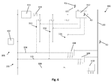
- FIG. 6 are shown in the simplified representation of the electrical power supply device 101 with the protective device 100 according to FIG. 1 three main such errors that occur in the protection device 100 itself and are also recognized by the protection device 100 itself, roughly symbolically represented symbolically.
- a failure of the measurement of the source voltage UQ in the source protection stage 111 and / or a disturbance of the transmission of the measured values of the source voltage UQ via the third signal transmission means 131 to the Central control stage 112 considered.
- this error F1 Upon the occurrence of this error F1, the comparison of the first, second and third load voltages UL1, UL2 and UL3, respectively, performed in the central control stage 112 for each of the network strings 104, 105 and 106, respectively, with the source voltage UQ provides a deviation exceeding the predetermined magnitude , and thus leads this result here to separate all network strands 104, 105, 106 from the energy source 102, since this deviation occurs in all network strands 104, 105, 106.
- This error F1 is thus treated as a result comparable to a detection of an undervoltage at the source protection stage 111.
- a disturbance or interruption of the signal transmission over the data bus 130 is assumed, whereby the exchange of data and / or control commands between the central control stage 112 on the one hand and the load protection stages 108, 109, 110 on the other hand via the Data bus 130 is interrupted or disturbed.
- the transmission of the measured values of the first, second or third load voltage UL1, UL2 or UL3 is thereby interrupted, a comparison of the first, second or third load voltage UL1, UL2 or UL3 with the source voltage UQ can no longer take place
- such a deviation from the predetermined size delivers all network strings 104, 105, 106 from the energy source 102 be separated.
- an emergency operation can optionally be provided here by selected by the network strands 104, 105 and 106 from the separation be excluded, so stay connected to the energy source.
- the source protection stage 111 with the central control stage 112, on the one hand, and the load protection stages 108, 109, 110, on the other hand independently operate independently of each other without signal transmission.
- a failure or failure of the central control stage 112 is assumed, so that a fault F2 similar situation arises, as well as the occurrence of the fault F3, the load protection stages 108, 109, 110 without signal transmission to each other and from or . to the central control stage 112, each independently working independently.
- the protection of the energy source 102 by the source protection stage 111 is also effective. First and foremost, only the monitoring of the individual load voltages UL1, UL2 and UL3 by the central control stage 112 is disabled, i.
- a substitute value for the source voltage UQ is used instead of this current measured value of the source voltage UQ by the microprocessor 163, preferably the last before the occurrence of the error F3 transmitted value of the source voltage UQ or the last detected by the voltage measuring device 151 of the load protection stages 108, 109 and 110 measured value of the load voltage UL1, UL2 or UL3 before the occurrence of the error F3.
- the invention thus provides a protective device for at least one energy source, in particular with a low overflow capability Energy transmission device with at least one network strand and at least one load connected to each network strand provided electrical energy supply device selectively protects the limited components of the energy transmission device and the energy source, containing per network strand a load protection via which the at least one load is connected, a source protection stage for switching off the power source at under or overvoltage at the power source, in each load protection stage, a measuring device for detecting a phase current and a load voltage and a switching device for disconnecting the power line from the power source when the strand current exceeds a predetermined limit, and a central control stage for each network strand comparing the Load voltage with a source voltage and for selectively separating those network strands in which a deviation between the load voltage and the source voltage vorbest immter size occurs.
- the protection device provides a hierarchical organization of the protection of the elements of the electrical power supply device comprising three levels of protection, wherein protection of the energy source is provided on a first of the protection levels.
- This protection operates independently of all other components of the electrical power supply and the protection device and even in the event of failure or failure of any auxiliary power supplies.
- the protection of the first protection level is therefore preferably suitable as a primary network protection.
- the load protection stages protect the network strings and the loads connected to them against locally occurring overcurrents, by which the protection of the energy source at the first protection level does not yet respond and therefore does not protect the network strands and the loads connected thereto can, provided.
- a detection of errors, in particular in the energy transmission device, ie in the network strands, is performed by the central control stage from an evaluation of current and voltage measured values of the individual load protection stages.
- the protection device also enables protection of the components of the energy supply device, a functional monitoring of the components of the energy supply device and the protection device as well as a so-called power management in the energy supply device.
- a simple and effective function monitoring of energy supply facilities and associated or associated resources, energy sources or energy producers and energy consumers is possible. For this purpose, in particular all detected current and voltage measured values are logged.
- short circuits due to defective - e.g. frayed - detect insulation that leads to longer burning arcs.
- These arcs can be detected on the one hand by the overcurrents caused by them, and by their characteristic current noise in the case of low arc currents, which can be detected at a frequency analysis of the current measured values carried out in the load protection stages.
- the protective device thus enables a secure protection of the components of the power supply from under- and overvoltages and the network strands and loads from overcurrents, the separation of faulty components of the power supply from the power source remains limited to a minimum, so that proper components of the power supply device or be affected as little as possible by such a separation.
- their permissible current intensities and the maximum permissible periods during which these permissible currents may be applied, in particular to prevent overheating, rated power of loads and associated tolerances as well as line resistances of the network strands can be very flexibly and precisely used in the signal processing equipment considered and adapted.
- the signal processing devices can advantageously be formed with a so-called assembly mode, ie a mode in which the signal processing devices compare nominal and actual values of, in particular, detected current and voltage measured values and, for example, faulty cables due to their deviations from the nominal value, but also missing ones. incorrectly connected, disturbing or defective loads can already be detected during the installation. Furthermore, there is the possibility of detection of ground faults or other errors in the insulation.
- the signal processing means of the protection device advantageously by a central computer connected via a data bus, detected faults - in particular insulation faults, overcurrents or defective components of the power supply device and / or the protective device - can be continuously logged. All of these features and properties are easily integrated in power supply facilities of a known type, such as vehicle electrical systems of land, air and / or water vehicles.
- the extensive use of electronic, ie semiconductor components in the construction of the protective device according to the invention a high vibration and acceleration resistance is achieved, which accommodates the use in vehicles.
- the signal processing devices of the protective device also allow a flexible adaptation of nominal values or characteristics of the energy supply device on the basis of measured values which have been obtained from measurements during an operating state of the energy supply device defined as normal operation.
- the signal processing means of the protection device can be constructed as learning systems. Remote control and remote maintenance are still possible via the central computer. If batteries or accumulators are used as energy sources in the energy supply device, their state of charge can be monitored and thus a deep discharge can be detected or prevented.
Abstract
Eine Schutzvorrichtung (100,300,400) für eine wenigstens eine Energiequelle (102), insbesondere mit geringer Überstromfähigkeit, eine Energieübertragungseinrichtung (103,303,403) mit wenigstens einem Netzstrang (104,105,106,304,404) und an jedem Netzstrang wenigstens eine angeschlossene Last (107) umfassende elektrische Energieversorgungseinrichtung (101,301,401), die selektiv eingegrenzte Bestandteile der Energieübertragungseinrichtung und die Energiequelle schützt, enthält je Netzstrang eine Lastschutzstufe (108,109,110,308), über die die wenigstens eine Last angeschlossen ist, eine Quellenschutzstufe (111) zum Abschalten der Energiequelle bei Unteroder Überspannung an der Energiequelle, in jeder Lastschutzstufe eine Messeinrichtung (150,151,350,351) zum Detektieren eines Strangstroms (IL,IL1,IL2,IL3) und einer Lastspannung (UL,UL1,UL2,UL3) sowie eine Schaltvorrichtung (153,353) zum Trennen des Netzstrangs von der Energiequelle, wenn der Strangstrom einen vorgebbaren Grenzwert überschreitet, und eine zentrale Steuerstufe (112,312) zum für jeden Netzstrang Vergleichen der Lastspannung mit einer Quellenspannung (UQ) und zum selektiven Trennen derjenigen Netzstränge, in denen zwischen der Lastspannung und der Quellenspannung eine Abweichung vorbestimmter Größe auftritt.A protective device (100, 300, 400) for an at least one energy source (102), in particular with low overcurrent capability, an energy transmission device (103, 303, 404) with at least one network strand (104, 105, 106, 404) and at each network strand at least one connected load (107) comprising electrical energy supply device (101, 301, 401), contains selectively limited components of the energy transfer device and the power source protects, contains per network strand a load protection stage (108,109,110,308), via which the at least one load is connected, a source protection stage (111) for switching off the power source under or over voltage at the power source, in each load protection stage a measuring device ( 150,151,350,351) for detecting a strand current (IL, IL1, IL2, IL3) and a load voltage (UL, UL1, UL2, UL3) and a switching device (153,353) for disconnecting the power line from the power source when the strand current has a predetermined limit rt, and a central control stage (112, 312) for comparing, for each network string, the load voltage with a source voltage (UQ) and selectively disconnecting those network strings in which a predetermined magnitude deviation occurs between the load voltage and the source voltage.
Description
Schutzvorrichtung für eine elektrische Energieversorgungseinrichtung und elektrische Energieversorgungseinrichtung mit einer derartigen SchutzvorrichtungProtective device for an electrical power supply device and electrical power supply device with such a protective device
Die Erfindung betrifft eine Schutzvorrichtung für eine elektrische Energieversorgungseinrichtung. Die Erfindung betrifft weiterhin eine elektrische Energieversorgungseinrichtung mit einer derartigen Schutzvorrichtung.The invention relates to a protective device for an electrical power supply device. The invention further relates to an electrical power supply device with such a protective device.
Aus der Druckschrift
Die Erfindung hat die Aufgabe, eine Schutzvorrichtung für eine elektrische Energieversorgungseinrichtung zu schaffen, mit der außer einem Schutz eines elektrischen Energieversorgungsnetzes und insbesondere selektiv nur verhältnismäßig eingegrenzter Netzbereiche zusätzlich ein wirksamer Schutz einer das elektrische Energieversorgungsnetz speisenden elektrischen Energieversorgungsquelle - kurz: Energiequelle - auch für Energiequellen mit geringer Überstromfähigkeit erzielt wird.The invention has the object to provide a protective device for an electrical power supply device with the addition of a protection of an electrical energy supply network and in particular only relatively limited network areas in addition effective protection of the electrical power grid feeding electrical energy source - short: energy source - for energy sources low overcurrent capability is achieved.
- wenigstens eine Energiequelle, insbesondere wenigstens eine Energiequelle mit geringer Überstromfähigkeit,at least one energy source, in particular at least one energy source with low overflow capability,
- eine Energieübertragungseinrichtung mit wenigstens einem Netzstrang undan energy transmission device with at least one network strand and
-
an jedem Netzstrang wenigstens eine daran angeschlossene Last, der Energie von der wenigstens einen Energiequelle über den Netzstrang zuführbar ist,
umfassende elektrische Energieversorgungseinrichtung,
enthaltend:at least one load connected thereto, to which energy can be supplied from the at least one energy source via the network strand, at each network strand,
comprehensive electrical power supply,
including: - je Netzstrang eine Lastschutzstufe, über die die wenigstens eine Last am Netzstrang angeschlossen ist,per network string a load protection stage, via which the at least one load is connected to the network string,
- wenigstens eine Quellenschutzstufe zum Abschalten der wenigstens einen Energiequelle bei Vorliegen einer Unter- oder Überspannung an der Energiequelle;at least one source protection stage for switching off the at least one energy source in the presence of an under or overvoltage at the energy source;
- in jeder Lastschutzstufe eine Messeinrichtung zum Detektieren eines Strangstroms und einer Lastspannung sowie eine Schaltvorrichtung zum Trennen des Netzstrangs von der Energiequelle, wenn der Strangstrom einen vorgebbaren Grenzwert überschreitet;in each load protection stage, a measuring device for detecting a phase current and a load voltage, and a switching device for disconnecting the power line from the power source when the phase current exceeds a predeterminable limit value;
- wenigstens eine zentrale Steuerstufe wenigstens zum für jeden Netzstrang Vergleichen der Lastspannung mit wenigstens einer von der wenigstens einen Energiequelle abgebbaren Quellenspannung und zum selektiven Trennen derjenigen Netzstränge von der wenigstens einen Energiequelle, in denen zwischen der Lastspannung und der Quellenspannung eine Abweichung vorbestimmter Größe auftritt.at least one central control stage at least for each network strand comparing the load voltage with at least one outputable from the at least one power source voltage and selectively disconnecting those network strands of the at least one energy source in which occurs between the load voltage and the source voltage, a deviation of predetermined size.
Der Energiequelle kommt dabei die Aufgabe zu, elektrische Energie über die Energieübertragungseinrichtung an die wenigstens eine Last zu liefern. Dabei kann die elektrische Energieversorgungseinrichtung mit einer oder mehreren Energiequellen ausgebildet sein, aus denen die wenigstens eine Last gespeist wird, d.h. die gemeinsam - voneinander abhängig oder unabhängig - Energie in die Energieübertragungseinrichtung speisen.The energy source has the task of supplying electrical energy via the energy transmission device to the at least one load. In this case, the electrical power supply device may be formed with one or more energy sources, from which the at least one load is fed, i. which together - depending on each other or independent - feed energy into the energy transfer device.
Besonders vorteilhaft ist die erfindungsgemäße Schutzvorrichtung mit einer Energiequelle einsetzbar, die eine geringe Überstromfähigkeit aufweist. Dabei kann diese eine geringe Überstromfähigkeit aufweisende Energiequelle sowohl zum Abgeben einer Wechselspannung als auch einer Gleichspannung als Quellenspannung eingerichtet sein. Als Überstromfähigkeit wird die Fähigkeit der Energiequelle bezeichnet, einen über einen Nennstrom, zu dessen Lieferung die Energiequelle dimensioniert und mit dem sie bestimmungsgemäß betreibbar ist, hinausgehenden Strom, d.h. Überstrom, zu liefern. Als gering in diesem Zusammenhang wird die Überstromfähigkeit bezeichnet, wenn sie nicht ausreicht, um eine konventionelle Überstrom-Zeitschutzschalteinrichtung auszulösen, wenn diese auf den Nennstrom der Energiequelle ausgelegt ist.Particularly advantageously, the protective device according to the invention can be used with an energy source which has a low overflow capability. In this case, this energy source having a low overcurrent capability can be set up both for outputting an AC voltage and a DC voltage as a source voltage. Overcurrent capability is defined as the ability of the power source to supply a current in excess of a nominal current to which the power source is dimensioned and with which it is intended to operate. Overcurrent, deliver. Low in this context, the overcurrent capability is referred to, if it is not sufficient to trigger a conventional overcurrent protection device when it is designed for the rated current of the power source.
Eine derartige, konventionelle Überstrom-Zeitschutzschalteinrichtung ist besonders bevorzugt gebildet durch eine herkömmliche Leitungssicherung, insbesondere durch einen herkömmlichen Sicherungsautomaten. Bei diesen erfolgt eine Auslösung regelmäßig dadurch, dass ein bestimmter Überstrom, der einem vorgebbaren Vielfachen eines in einem Netzstrang der Energieübertragungseinrichtung, d.h. z.B. in einer zu sichernden Leitung eines Energieversorgungsnetzes, zulässigen Nennstroms entspricht, über die Dauer eines vorgebbaren Zeitintervalls hinweg fließt. Bei Haushalts-Sicherungsautomaten weist dieser Überstrom z.B. eine Größenordnung vom Zwei- bis Dreifachen des Nennstroms und das Zeitintervall eine Dauer von einigen Sekundenbruchteilen auf.Such a conventional overcurrent time protection switching device is particularly preferably formed by a conventional line fuse, in particular by a conventional circuit breaker. In these, tripping occurs regularly in that a certain overcurrent, which corresponds to a predefinable multiple of a rated current permissible in a network string of the energy transmission device, ie, for example, in a line of a power supply network to be protected, flows over the duration of a predefinable time interval. For household circuit breakers, this overcurrent, for example, a magnitude of two to Three times the rated current and the time interval has a duration of a few second fractions.
Die Energieübertragungseinrichtung ist dazu eingerichtet, die elektrische Energie von der Energiequelle bzw. den Energiequellen über den wenigstens einen Netzstrang an die wenigstens eine Last zu übertragen. Bevorzugt ist die Energieübertragungseinrichtung als Energieversorgungsnetz - kurz: Netz - zur Versorgung der wenigstens einen Last gestaltet. Ein Netzstrang ist dabei ein Zweig des Netzes, an dem - über eine Lastschutzstufe - wenigstens eine Last angeschlossen ist. Daneben kann das Netz weitere Bestandteile, z.B. weitere Zweige oder Abschnitte, umfassen.The energy transmission device is configured to transmit the electrical energy from the energy source or the energy sources via the at least one network strand to the at least one load. Preferably, the energy transmission device is designed as a power supply network - in short: network - to supply the at least one load. A network strand is a branch of the network to which - via a load protection stage - at least one load is connected. In addition, the network may contain other components, e.g. other branches or sections.
Der wenigstens einen Last ist die elektrische Energie von der wenigstens einen Energiequelle über das Netz zuführbar. Die wenigstens eine Energiequelle, das Netz und die wenigstens eine Last sind also dazu eingerichtet, dass elektrische Energie von der wenigstens einen Energiequelle über das Netz der wenigstens einen Last zugeführt wird.The at least one load can be supplied with the electrical energy from the at least one energy source via the network. The at least one energy source, the network and the at least one load are thus configured to supply electrical energy from the at least one energy source via the network to the at least one load.
Bei der erfindungsgemäßen Schutzvorrichtung sind in jeder Lastschutzstufe eine Messeinrichtung zum Detektieren eines Strangstroms und einer Lastspannung sowie eine Schaltvorrichtung zum Trennen des Netzstrangs von der Energiequelle, wenn der Strangstrom einen vorgebbaren Grenzwert überschreitet, vorgesehen. Dabei ist als Lastspannung diejenige elektrische Spannung bezeichnet, die im Betrieb der elektrischen Energieversorgungseinrichtung, d.h. der erfindungsgemäßen Schutzvorrichtung, an der Last, d.h. deren Anschlüssen, gemessen wird. Als Strangstrom ist ferner der Strom in einem Netzstrang bezeichnet. Dieser Strangstrom entspricht der Summe aller Ströme in allen Lasten, die an diesen einen Netzstrang angeschlossen sind.In the protection device according to the invention in each load protection stage, a measuring device for detecting a phase current and a load voltage and a switching device for disconnecting the power line from the power source, when the strand current exceeds a predetermined limit provided. In this case, the load voltage is that electrical voltage which, during operation of the electrical power supply device, i. the protective device according to the invention, on the load, i. whose terminals, is measured. As a strand current, the current is also referred to in a network strand. This string current corresponds to the sum of all currents in all loads connected to this one network string.
Somit ist jede der Lastschutzstufen ausgebildet mit wenigstens einer Messeinrichtung zum Detektieren eines Strangstroms und einer Lastspannung sowie mit einer Schaltvorrichtung zum Trennen des Netzstrangs von der Energiequelle, wenn der Strangstrom einen vorgebbaren Grenzwert überschreitet. Je eine solche Messeinrichtung und je eine solche Schaltvorrichtung sind somit als Mindestausstattung von jeder der Lastschutzstufen umfasst, so dass jede Lastschutzstufe wenigstens einen Überstromschutz für den zugehörigen Strang und eine Lastspannungsmessung aufweist. Die Ausgestaltung der erfindungsgemäßen Schutzvorrichtung mit wenigstens einer Quellenschutzstufe zum Abschalten der wenigstens einen Energiequelle bei Vorliegen einer Unter- oder Überspannung an der Energiequelle ermöglicht einen selektiven Schutz jeder der wenigstens einen Energiequelle unabhängig vom Schutz der Energieübertragungseinrichtung bzw. des wenigstens einen Netzstrangs und der wenigstens einen Last durch die wenigstens eine Lastschutzstufe. Dazu wird detektiert, ob eine Spannung an der Energiequelle, d.h. eine von der Energiequelle abgegebene Spannung - kurz: Quellenspannung - einen vorgegebenen oberen Schwellenwert überschreitet oder einen vorgegebenen unteren Schwellenwert unterschreitet. Das Abschalten sowohl bei Auftreten einer Unterspannung als auch bei einer Überspannung ermöglicht einen einfachen und universellen Schutz der Energiequelle gegen unterschiedliche Fehler sowie einen wirksamen Schutz auch von Energiequellen unterschiedlicher Ausbildungen. Insbesondere wird dadurch ein wirksamer Schutz auch von Energiequellen mit geringer Überstromfähigkeit erzielt, z.B. von mit Brennstoffzellen, Photovoltaikelementen oder dergleichen ausgebildeten Energiequellen.Thus, each of the load protection stages is formed with at least one measuring device for detecting a phase current and a load voltage and with a switching device for disconnecting the power line from the power source when the phase current exceeds a predeterminable limit. Each such measuring device and each such switching device are thus included as minimum equipment of each of the load protection stages, so that each load protection stage has at least one overcurrent protection for the associated strand and a load voltage measurement. The embodiment of the protective device according to the invention with at least one source protection stage for switching off the at least one energy source in the presence of under or overvoltage at the energy source allows selective protection of each of the at least one energy source independent of the protection of the energy transmission device or the at least one network strand and the at least one load by the at least one load protection stage. For this purpose, it is detected whether a voltage at the energy source, ie a voltage delivered by the energy source - in short: source voltage - exceeds a predetermined upper threshold or falls below a predetermined lower threshold. Switching off both when an undervoltage occurs and when overvoltage allows a simple and universal protection of the energy source against different errors as well as effective protection of energy sources of different configurations. In particular, an effective protection of energy sources with low overcurrent capability is thereby achieved, for example of energy sources formed with fuel cells, photovoltaic elements or the like.
Die erfindungsgemäße Schutzvorrichtung enthält schließlich wenigstens eine zentrale Steuerstufe wenigstens zum für jeden Netzstrang Vergleichen der Lastspannung mit wenigstens einer von der wenigstens einen Energiequelle abgebbaren Quellenspannung und zum selektiven Trennen derjenigen Netzstränge von der wenigstens einen Energiequelle, in denen zwischen der Lastspannung und der Quellenspannung eine Abweichung vorbestimmter Größe auftritt. Sofern keine oder nur eine Abweichung auftritt, die geringer ist als die vorgenannte Abweichung vorbestimmter Größe, werden die Netzstränge von der wenigstens einen zentralen Steuerstufe mit der Energiequelle verbunden, d.h., die wenigstens eine zentrale Steuerstufe ist ausgebildet zum Verbinden der Netzstränge mit der Energiequelle in diesem Fall. Im Einzelnen bedeutet dies, dass die wenigstens eine zentrale Steuerstufe wenigstens
- zum für jeden Netzstrang durchzuführenden Vergleichen der Lastspannung, die in diesem Netzstrang auftritt, mit der Quellenspannung,
- zum selektiven Trennen derjenigen Netzstränge von der wenigstens einen Energiequelle, in den eine Abweichung vorbestimmter Größe auftritt, und
- ansonsten zum Verbinden der Netzstränge mit der wenigstens einen Energiequelle
- for comparing the load voltage occurring in this network string with the source voltage for each network string,
- for selectively separating those network strands from the at least one energy source into which a deviation of a predetermined size occurs, and
- otherwise for connecting the network strands to the at least one energy source
Vorteilhafte Ausgestaltungen der Erfindung sind in den Unteransprüchen gekennzeichnet.Advantageous embodiments of the invention are characterized in the subclaims.
Gemäß einer bevorzugten Weiterbildung der erfindungsgemäßen Schutzvorrichtung ist zu jeder Energiequelle wenigstens eine, bevorzugt genau eine, Quellenschutzstufe vorgesehen. Diese Quellenschutzstufe dient zum Abschalten der Energiequelle bei Vorliegen einer Unter- oder Überspannung an der Energiequelle und damit dem individuellen Schutz genau dieser Energiequelle durch ein gemeinsames Trennen aller aus dieser Energiequelle gespeisten Netzstränge von dieser Energiequelle bei Feststellung einer Unter- oder Überspannung an der Energiequelle. Wahlweise kann auch vorgesehen sein, dass nicht alle, sondern einer oder mehrere, d.h. nur eine Teilanzahl, der von dieser Energiequelle gespeisten Netzstränge bei Vorliegen einer Unter- oder Überspannung an der Energiequelle von dieser Energiequelle getrennt, d.h. abgeschaltet, werden. Auf diese Weise kann z.B. bei einer Überlastung der Energiequelle eine gezielte Abschaltung von Netzsträngen mit Lasten erfolgen, die für den Betrieb der Energieversorgungseinrichtung von geringerer Bedeutung sind, aber die Speisung von Netzsträngen mit für den Betrieb der Energieversorgungseinrichtung hoher Bedeutung aufrechterhalten werden. In einer weiteren Variation können Netzstränge stufenweise von der Energiequelle getrennt und kann dadurch die Energiequelle stufenweise entlastet werden, bevorzugt bis zu einem Betriebszustand, in dem die genannte Überlastung beseitigt ist.According to a preferred development of the protective device according to the invention, at least one, preferably exactly one, source protection stage is provided for each energy source. This source protection stage is used to shut off the power source in the presence of under or over voltage at the power source and thus the individual protection of exactly this energy source by jointly disconnecting all fed from this energy source network strands of this energy source upon detection of under- or over-voltage at the power source. Optionally, it may also be provided that not all, but one or more, i. only a part number, the power lines fed by this power source in the presence of a negative or overvoltage at the power source separated from this power source, i. shut off. In this way, e.g. in an overload of the power source targeted shutdown of network strands with loads that are of less importance for the operation of the power supply device, but the supply of mains lines are maintained with for the operation of the power supply of high importance. In a further variation, power lines may be gradually disconnected from the power source and thereby the power source may be relieved incrementally, preferably to an operating condition in which said over-load is eliminated.
Bei einer weiteren bevorzugten Ausführungsform der erfindungsgemäßen Schutzvorrichtung ist zu jeder Energiequelle wenigstens eine, bevorzugt genau eine, zentrale Steuerstufe vorgesehen. Durch eine derartige Zuordnung von Energiequelle bzw. Energiequellen einerseits und zentraler Steuerstufe bzw. zentralen Steuerstufen andererseits kann die vorbeschriebene Überwachung, d.h. das Vergleichen, der Lastspannung bzw. Lastspannungen und der Quellenspannung bzw. Quellenspannungen besonders einfach und betriebssicher ausgeführt werden.In a further preferred embodiment of the protective device according to the invention, at least one, preferably exactly one, central control stage is provided for each energy source. By such an assignment of energy source or energy sources on the one hand and central control stage or central control stages on the other hand, the above-described monitoring, ie comparing, the load voltage or load voltages and the source voltage or source voltages are performed particularly simple and reliable.
Nach einer weiteren bevorzugten Ausführungsform der erfindungsgemäßen Schutzvorrichtung ist für jeden des wenigstens einen Netzstrangs je eine, insbesondere mit einem Relais ausgebildete, zweite Schaltvorrichtung vorgesehen, die durch die wenigstens eine Quellenschutzstufe, insbesondere durch die Quellenschutzstufe der Energiequelle, aus der der betreffende Netzstrang speisbar ist, steuerbar ist zum Verbinden des betreffenden Netzstrangs mit der Energiequelle bzw. zum Trennen des betreffenden Netzstrangs von der Energiequelle. Im Betrieb wird also die je eine zweite Schaltvorrichtung für jeden des wenigstens einen Netzstrangs durch die wenigstens eine Quellenschutzstufe, insbesondere durch die Quellenschutzstufe der Energiequelle, aus der der wenigstens eine Netzstrang gespeist wird, gesteuert zum Verbinden bzw. Trennen des betreffenden Netzstrangs mit bzw. von der Energiequelle. Vorteilhaft sind dabei die wenigstens eine Quellenschutzstufe und/oder die wenigstens eine zentrale Steuerstufe mit der zweiten Schaltvorrichtung bzw. den zweiten Schaltvorrichtungen in einer Baugruppe zusammengefasst, z.B. gemeinsam in einer Art von Schaltkasten bzw. Verteilerkasten aufgenommen.According to a further preferred embodiment of the protective device according to the invention, a respective second switching device is provided for each of the at least one network string, in particular with a relay, which can be fed by the at least one source protection stage, in particular by the source protection stage of the energy source from which the relevant network string is fed. is controllable to connect the respective network strand with the power source or to disconnect the relevant network strand from the power source. In operation, therefore, the respective second switching device for each of the at least one network string is controlled by the at least one source protection stage, in particular by the source protection stage of the power source from which the at least one network string is fed to connect or disconnect the respective network string with or from the source of energy. Advantageously, the at least one source protection stage and / or the at least one central control stage with the second switching device or the second switching devices are combined in an assembly, e.g. taken together in a kind of control box or distribution box.
In einer bevorzugten Weiterbildung der erfindungsgemäßen Schutzvorrichtung ist eine Signalübertragungseinrichtung vorgesehen zum Verbinden wenigstens der wenigstens einen zentralen Steuerstufe und wenigstens einer der einen oder mehreren Lastschutzstufen miteinander zum Übertragen wenigstens eines von der Messeinrichtung der Lastschutzstufe bzw. Lastschutzstufen detektierten Strangstroms und/oder einer von der Messeinrichtung der Lastschutzstufe bzw. Lastschutzstufen detektierten Lastspannung an die wenigstens eine zentrale Steuerstufe. Insbesondere ist eine mit einem Datenbus ausgebildete Signalübertragungseinrichtung vorgesehen, wobei ein solcher Datenbus vorteilhaft nach an sich bekannten Bauformen und Standards ausgebildet ist. Damit ist eine sehr einfache, leistungsfähige und schnelle Übertragung von Daten möglich, die Messwerte des wenigstens einen detektierten Strangstroms und/oder der wenigstens einen detektierten Lastspannung umfassen, und umgekehrt kann auch eine Übertragung von Daten und/oder Steuerbefehlen von der wenigstens einen zentralen Steuerstufe an die Lastschutzstufe bzw. Lastschutzstufen sehr einfach, leistungsfähig und schnell vorgenommen werden.In a preferred development of the protective device according to the invention, a signal transmission device is provided for connecting at least the at least one central control stage and at least one of the one or more load protection stages to each other for transmitting at least one strand current detected by the measuring device of the load protection stage or load protection stages and / or one of the measuring device Load protection stage or load protection stages detected load voltage to the at least one central control stage. In particular, a trained with a data bus signal transmission device is provided, wherein such a data bus is advantageously formed according to known designs and standards. Thus, a very simple, efficient and rapid transmission of data is possible, comprising the measured values of the at least one detected phase current and / or the at least one detected load voltage, and vice versa, a transmission of data and / or control commands from the at least one central control stage the load protection stage or load protection stages are made very simple, powerful and fast.
Eine bevorzugte Weiterbildung der erfindungsgemäßen Schutzvorrichtung ist dadurch gekennzeichnet, dass die wenigstens eine zentrale Steuerstufe und/oder die wenigstens eine Lastschutzstufe mit je wenigstens einer Signalverarbeitungseinrichtung, insbesondere digitalen Signalverarbeitungseinrichtung, bevorzugt mit einem Mikroprozessor ausgebildeten Signalverarbeitungseinrichtung, d.h. einer programmierbaren Steuereinrichtung, ausgestaltet sind. Insbesondere die Ausgestaltung der wenigstens einen Lastschutzstufe mit einer digitalen Signalverarbeitungseinrichtung ermöglicht außer einer Aufbereitung der vorgenannten Messwerte des wenigstens einen detektierten Strangstroms und/oder der wenigstens einen detektierten Lastspannung in digitale Daten auch eine Vielzahl weiterer Steuerfunktionen, die einfach und flexibel wählbar in der wenigstens einen Lastschutzstufe ausgebildet sein können.A preferred embodiment of the protective device according to the invention is characterized in that the at least one central control stage and / or the at least one load protection stage, each with at least one signal processing device, in particular digital signal processing device, preferably with a microprocessor-based signal processing device, i. a programmable controller, are configured. In particular, the design of the at least one load protection stage with a digital signal processing device allows not only a preparation of the aforementioned measured values of the at least one detected phase current and / or the at least one detected load voltage in digital data, a variety of other control functions, the simple and flexible selectable in the at least one load protection stage can be trained.
In einer weiteren bevorzugten Ausführungsform der erfindungsgemäßen Schutzvorrichtung ist eine weitere Signalübertragungseinrichtung vorgesehen, über die wenigstens die wenigstens eine zentrale Steuerstufe mit weiteren, externen Signalverarbeitungseinrichtungen, insbesondere mit Einrichtungen zu einer Protokollierung von Betriebszuständen der Schutzvorrichtung und/oder mit Einrichtungen zu einer Fernsteuerung und/oder Fernwartung, verbunden ist, wobei bevorzugt die weitere Signalübertragungseinrichtung mit einem Datenbus ausgebildet ist. Besonders bevorzugt ist die weitere Signalübertragungseinrichtung mit dem Datenbus ausgestaltet, mit dem die Signalübertragungseinrichtung zum Verbinden wenigstens der wenigstens einen zentralen Steuerstufe und wenigstens einer der einen oder mehreren Lastschutzstufen ausgebildet ist, d.h. beide Signalübertragungseinrichtungen sind in einem einzigen Datenbus zusammengefasst, wodurch ein besonders einfacher und zuverlässiger Aufbau erzielt wird. Die weiteren, externen Signalverarbeitungseinrichtungen sind bevorzugt ebenfalls mit wenigstens einer digitalen Signalverarbeitungseinrichtung, insbesondere einem Rechner, z.B. einem Zentralrechner, ausgebildet. Die vorgenannten Einrichtungen zur Protokollierung und/oder Fernsteuerung und/oder Fernwartung lassen sich damit sehr einfach und leistungsfähig ausgestalten. Dadurch kann der Betrieb der Energieversorgungseinrichtung, insbesondere der darin eingesetzten Schutzvorrichtung, in sehr leistungsfähiger, vielseitiger und flexibler Weise durchgeführt werden. Bevorzugt lassen sich über die Protokollierung der Betriebszustände auch sehr einfach Anforderungen an eine Aufzeichnung eines Betriebsablaufs einer solchen Energieversorgungseinrichtung z.B. in einem Luftfahrzeug erfüllen. Eine weitere, vorteilhafte Nutzung der Protokollierung und/oder Fernwartung besteht darin, dass eine wenigstens teilautomatisierte Fehlererkennung durchführbar ist einschließlich einer - ebenfalls wenigstens teilautomatischen - Abgabe einer Bestellung von Ersatzteilen für die Energieversorgungseinrichtung.In a further preferred embodiment of the protective device according to the invention, a further signal transmission device is provided, via which at least the at least one central control stage with further external signal processing devices, in particular with devices for logging operating states of the protective device and / or with devices for remote control and / or remote maintenance , is connected, wherein preferably the further signal transmission device is formed with a data bus. Particularly preferably, the further signal transmission device is designed with the data bus with which the signal transmission device is designed for connecting at least the at least one central control stage and at least one of the one or more load protection stages, ie both signal transmission means are combined in a single data bus, whereby a particularly simple and reliable Structure is achieved. The further, external signal processing devices are preferably also formed with at least one digital signal processing device, in particular a computer, for example a central computer. The aforementioned means for logging and / or remote control and / or remote maintenance can be made very simple and powerful. As a result, the operation of the power supply device, in particular the protective device used therein, can be carried out in a very powerful, versatile and flexible manner. Preferably, logging of the operating states also makes it very easy to fulfill requirements for recording an operating sequence of such a power supply device, for example in an aircraft. Another advantageous use of logging and / or remote maintenance is that a at least partially automated error detection is feasible including a - also at least partially automatic - delivery of an order of spare parts for the power supply device.
Bei einer anderen Ausführungsform der erfindungsgemäßen Schutzvorrichtung ist die wenigstens eine Signalverarbeitungseinrichtung der wenigstens einen zentralen Steuerstufe wenigstens eingerichtet für
- ein Steuern eines Verbindens und/oder Trennens wenigstens einer der Lasten mit bzw. von der Energiequelle in Abhängigkeit wenigstens von einer verfügbaren Leistungsabgabe der Energiequelle,
- ein Erkennen hochohmiger Kurzschlüsse und/oder Isolationsfehler wenigstens in einem des wenigstens einen Netzstrangs wenigstens auf Grundlage wenigstens eines vorgegebenen Leitungswiderstands des wenigstens einen Netzstrangs, wenigstens eines gemessenen Strangstroms und wenigstens einer gemessenen Lastspannung,
- ein Erkennen gegenüber einem Sollzustand veränderter Impedanzen und/oder von Unterbrechungen in wenigstens einem des wenigstens einen Netzstrangs und/ oder in wenigstens einem sonstigen Zweig der Energieübertragungseinrichtung.
- controlling a connection and / or disconnection of at least one of the loads with and from the energy source in dependence on at least one available power output of the energy source,
- detecting high-resistance shorts and / or insulation faults at least in one of the at least one network strand based at least on a predetermined line resistance of the at least one network strand, at least one measured strand current and at least one measured load voltage
- a recognition of a desired state of changed impedances and / or of interruptions in at least one of the at least one network strand and / or in at least one other branch of the energy transmission device.
Das Verbinden und/oder Trennen der wenigstens einen der Lasten mit bzw. von der Energiequelle in Abhängigkeit wenigstens von der verfügbaren Leistungsabgabe der Energiequelle, also das Zu- und/oder Abschalten wenigstens einer der Lasten von der Energiequelle abhängig von deren Leistungsfähigkeit und Auslastung, ist vorteilhaft einsetzbar für ein sogenanntes "Energiemanagement", durch das die Effizienz elektrischer Anlagen wie insbesondere Energieversorgungseinrichtungen erhöht werden soll. Je nach Bedarf oder Notwendigkeit einer Leistungsverringerung in einzelnen Netzsträngen und/oder einem sonstigen Zweig der Energieübertragungseinrichtung können Lasten von der Energieübertragungseinrichtung getrennt oder auch wieder zugeschaltet werden. Für eine Bestimmung, welche Last, d.h. welcher Netzstrang, ab- bzw. zugeschaltet wird, können bevorzugt auch die Messwerte des wenigstens einen detektierten Strangstroms und/oder der wenigstens einen detektierten Lastspannung ausgewertet werden. Durch die wenigstens eine Signalverarbeitungseinrichtung der wenigstens einen zentralen Steuerstufe und/oder die wenigstens eine Signalverarbeitungseinrichtung der wenigstens einen Lastschutzstufe ist eine derartige Auswertung und Steuerung sehr einfach und flexibel ausführbar.The connection and / or disconnection of the at least one of the loads with and from the energy source in dependence on at least the available power output of the energy source, ie the switching on and / or off of at least one of the loads from the power source depending on their performance and capacity utilization can be used advantageously for a so-called "energy management", by which the efficiency of electrical systems, in particular energy supply facilities to be increased. Depending on the need or need for power reduction in individual network lines and / or another branch of the energy transmission device loads can be disconnected from the power transmission device or switched on again. For a determination of which load, ie which network link, is switched off or switched on, the measured values of the at least one detected phase current and / or the at least one detected load voltage may also be preferred be evaluated. By means of the at least one signal processing device of the at least one central control stage and / or the at least one signal processing device of the at least one load protection stage, such an evaluation and control can be carried out very simply and flexibly.
Die Messwerte des wenigstens einen detektierten Strangstroms und/oder der wenigstens einen detektierten Lastspannung sind ferner vorteilhaft auch dazu auswertbar, hochohmige Kurzschlüsse und/oder Isolationsfehler in dem wenigstens einen Netzstrang zu erkennen. Dafür werden ferner der vorgegebene Leitungswiderstand des wenigstens einen Netzstrangs sowie die Quellenspannung herangezogen. Bei fehlerfreiem Netzstrang muss der Messwert der Lastspannung mit einem nach dem ohmschen Gesetz aus Quellenspannung, Leitungswiderstand und Strangstrom ermittelten Sollwert dieser Lastspannung übereinstimmen. Hochohmige Kurzschlüsse und/oder Isolationsfehler machen sich über zusätzliche Ströme bemerkbar, die zusätzliche Spannungsabfälle im betroffenen Netzstrang verursachen. Messwert und Sollwert der Lastspannung stimmen nicht mehr überein. Liegt also eine Abweichung vor, wird dies als hochohmiger Kurzschluss und/oder Isolationsfehler erkannt.The measured values of the at least one detected phase current and / or the at least one detected load voltage can also advantageously be evaluated to detect high-resistance shorts and / or insulation faults in the at least one network line. For this purpose, furthermore, the predetermined line resistance of the at least one network string as well as the source voltage are used. In the case of a fault-free network string, the measured value of the load voltage must correspond to a setpoint of this load voltage determined according to Ohm's law of source voltage, line resistance and phase current. High-impedance shorts and / or insulation faults are noticeable via additional currents, which cause additional voltage drops in the affected network strand. Measured value and setpoint of the load voltage no longer match. So if there is a deviation, this is detected as a high-impedance short circuit and / or insulation fault.
Das Erkennen gegenüber einem Sollzustand veränderter Impedanzen und/oder von Unterbrechungen in wenigstens einem des wenigstens einen Netzstrangs und/ oder in wenigstens einem sonstigen Zweig der Energieübertragungseinrichtung erfolgt vorteilhaft in vergleichbarer Weise auf Grundlage des wenigstens einen vorgegebenen Leitungswiderstands des wenigstens einen Netzstrangs sowie gemessenem Strangstrom und gemessener Lastspannung.The recognition of a nominal state of changed impedances and / or of interruptions in at least one of the at least one network branch and / or in at least one other branch of the energy transmission device advantageously takes place in a comparable manner on the basis of the at least one predetermined line resistance of the at least one network branch and measured phase current and measured load voltage.
Nach einer anderen Ausführungsform der erfindungsgemäßen Schutzvorrichtung ist die wenigstens eine Signalverarbeitungseinrichtung der wenigstens einen Lastschutzstufe des wenigstens einen Netzstrangs wenigstens eingerichtet für
- ein Auswerten des von der Messeinrichtung der wenigstens einen Lastschutzstufe detektierten Strangstroms und/oder der von der Messeinrichtung der wenigstens einen Lastschutzstufe detektierten Lastspannung, bevorzugt von deren Augenblickswerten und/oder deren zeitlichen Verläufen, sowie
- ein daraus Erkennen wenigstens eines Fehlerstroms in dem wenigstens einen Netzstrang.
- an evaluation of the strand current detected by the measuring device of the at least one load protection stage and / or the load voltage detected by the measuring device of the at least one load protection stage, preferably of their instantaneous values and / or their temporal progressions, as well as
- a detection of at least one fault current in the at least one network string.
Wie nachstehend noch näher erläutert, wird die hier beschriebene Energieversorgungseinrichtung vorteilhaft durch wenigstens eine als Gleich- und/oder Wechselspannung ausgebildete Quellenspannung gespeist, wobei Frequenzen dieser Quellenspannung bevorzugt gering gegenüber Arbeits- und/oder Taktfrequenzen sind, wie sie zum Betrieb üblicher Signalverarbeitungseinrichtungen, insbesondere digitaler Signalverarbeitungseinrichtungen, bevorzugt mit einem Mikroprozessor ausgebildeter Signalverarbeitungseinrichtungen, benutzt werden. Damit ist es möglich, mit der erfindungsgemäß ausgebildeten wenigstens einen zentralen Steuerstufe und/oder Lastschutzstufe sehr präzise Messungen zeitlicher Verläufe der wenigstens einen Lastspannung und des wenigstens einen Strangstroms vorzunehmen. Aus den dabei gewonnenen Messwerten lassen sich Abweichungen dieser zeitlichen Verläufe von vorgebbaren Sollverläufen ermitteln. Vorteilhaft werden derartige Abweichungen des wenigstens einen Strangstroms als Fehlerstrom erkannt, und dieser Fehlerstrom wird als Auslöser zum Trennen des Netzstrangs von der Energiequelle mit Hilfe der Schaltvorrichtung der Lastschutzstufe des betroffenen Netzstrangs herangezogen. Eine derartige Fehlerstromerkennung ist wesentlich genauer und reagiert auf Fehlerströme bedeutend empfindlicher als eine herkömmliche Effektivwertmessung eines Fehlerstroms, so dass eine gegenüber z.B. herkömmlichen FI-Schaltern wesentlich gesteigerte Präzision und Empfindlichkeit in der Erkennung von Fehlerströmen erzielt wird.As explained in more detail below, the energy supply device described here is advantageously fed by at least one source voltage designed as a direct and / or alternating voltage, frequencies of this source voltage preferably being low in relation to operating and / or clock frequencies, as is the case with conventional signal processing devices, in particular digital ones Signal processing means, preferably with a microprocessor trained signal processing means used. This makes it possible to carry out with the inventively designed at least one central control stage and / or load protection stage very precise measurements of time profiles of at least one load voltage and the at least one string current. From the measured values obtained, it is possible to determine deviations of these temporal courses from predefinable target progressions. Advantageously, such deviations of the at least one phase current are recognized as a fault current, and this residual current is used as a trigger for disconnecting the network strand from the energy source with the aid of the switching device of the load protection stage of the affected network strand. Such a fault current detection is much more accurate and responds to fault currents significantly more sensitive than a conventional rms measurement of a fault current, so that a comparison with e.g. significantly increased precision and sensitivity in the detection of fault currents is achieved in conventional FI switches.
Aus den gewonnenen Messwerten der zeitlichen Verläufe der wenigstens einen Lastspannung und des wenigstens einen Strangstroms lassen sich weiterhin Amplituden, Phasenwinkel, Blind- und Wirkströme sowie Blind- und Wirkwiderstände bzw. Blind- und Wirkleistungen im wenigstens einen Netzstrang bestimmen. Somit lassen sich unmittelbar elektrische Eigenschaften der wenigstens einen über den wenigstens einen Netzstrang gespeisten Last ermitteln. Weichen diese Eigenschaften von vorgegebenen Sollwerten ab, wird diese Abweichung vorteilhaft als Auslöser zum Trennen des Netzstrangs von der Energiequelle mit Hilfe der Schaltvorrichtung der Lastschutzstufe des betroffenen Netzstrangs herangezogen.From the measured values of the time profiles of the at least one load voltage and of the at least one phase current, it is also possible to determine amplitudes, phase angles, reactive and active currents as well as reactive and reactive resistances or reactive and active powers in the at least one network link. Thus, electrical properties of the at least one load fed via the at least one network string can be determined directly. If these properties deviate from predetermined desired values, this deviation is advantageously used as a trigger for disconnecting the network strand from the energy source with the aid of the switching device of the load protection stage of the affected network strand.
Wahlweise oder zusätzlich zum Trennen des Netzstrangs von der Energiequelle können die Abweichungen, insbesondere Fehlerströme, über die Signalübertragungseinrichtung, bevorzugt den Datenbus, an die wenigstens eine zentrale Steuerstufe und/oder an weitere, externe Signalverarbeitungseinrichtungen gemeldet werden.Optionally, or in addition to disconnecting the network strand from the energy source, the deviations, in particular fault currents, via the signal transmission device, preferably the data bus to which at least one central control stage and / or to other, external signal processing means are reported.
Gemäß einer bevorzugten Weiterbildung der erfindungsgemäßen Schutzvorrichtung ist jeder Quellenschutzstufe je eine Gleichspannungsumformeinrichtung, insbesondere ausgebildet mit einem Gleichspannungswandler, nachgeschaltet zum Umformen einer von der Quellenschutzstufe abgegebenen Spannung in eine Schutzkleinspannung zum Betreiben der wenigstens einen zweiten Schaltvorrichtung und/oder der wenigstens einen zentralen Steuerstufe. Diese Weiterbildung ist vorteilhaft einsetzbar, sofern eine Energiequelle mit einer Quellenspannung zum Einsatz kommt, die diese Schutzkleinspannung übersteigt, insbesondere wesentlich übersteigt; z.B. beträgt die Quellenspannung bis zu einigen hundert Volt, wohingegen als Schutzkleinspannung höchstens 42 Volt zugelassen sind. Bei einer bevorzugten Ausgestaltung der Quellenschutzstufe derart, dass die von der Quellenschutzstufe abgegebene Spannung bis auf schaltungsbedingte Spannungsverluste der Quellenspannung entspricht, übersteigt dann auch die von der Quellenschutzstufe abgegebene Spannung die genannte Schutzkleinspannung. Dies ist aber zum Betreiben der wenigstens einen zweiten Schaltvorrichtung und/oder der wenigstens einen zentralen Steuerstufe nachteilig und unerwünscht, da z.B. mit Halbleiterschaltungen üblicher Bauart aufgebaute, insbesondere digitale, Signalverarbeitungseinrichtungen mit sehr viel geringeren Versorgungs- und/oder Signalspannungen betrieben werden. Außerdem wird bei einem Betreiben der wenigstens einen zweiten Schaltvorrichtung und/oder der wenigstens einen zentralen Steuerstufe mit einer die Schutzkleinspannung übersteigenden Spannung eine Überprüfung und/oder Wartung und/oder Reparatur der erfindungsgemäßen Schutzvorrichtung erschwert, da an dieser dann nicht mehr unter Spannung gearbeitet werden kann bzw. darf. Das Betreiben mit einer Schutzkleinspannung vermeidet diese Nachteile.According to a preferred development of the protection device according to the invention, each source protection stage is followed by a DC voltage conversion device, in particular designed with a DC-DC converter, downstream for converting a voltage delivered by the source protection stage into a protective extra-low voltage for operating the at least one second switching device and / or the at least one central control stage. This development can be used advantageously if an energy source with a source voltage is used which exceeds this safety extra-low voltage, in particular substantially exceeds it; e.g. the source voltage is up to a few hundred volts, whereas at most 42 volts are permitted as protective extra-low voltage. In a preferred embodiment of the source protection stage in such a way that the voltage delivered by the source protection stage corresponds to the source voltage except for circuit-related voltage losses, then the voltage delivered by the source protection stage also exceeds said protective extra-low voltage. However, this is disadvantageous and undesirable for operating the at least one second switching device and / or the at least one central control stage, since e.g. constructed with semiconductor circuits of conventional design, in particular digital, signal processing facilities are operated with much lower supply and / or signal voltages. In addition, when the at least one second switching device and / or the at least one central control stage is operated with a voltage exceeding the protective extra-low voltage, it becomes more difficult to check and / or maintain and / or repair the protective device according to the invention, because then it can no longer be operated under voltage or allowed. Operating with a safety extra-low voltage avoids these disadvantages.
Bei einer weiteren bevorzugten Ausführungsform der erfindungsgemäßen Schutzvorrichtung ist die wenigstens eine Energiequelle zum Liefern wenigstens einer Gleichspannung eingerichtet, durch die der wenigstens einen Last Energie von der wenigstens einen Energiequelle zuführbar ist. Dies stellt eine bevorzugte Ausgestaltung der mit der erfindungsgemäßen Schutzvorrichtung ausgebildeten Energieversorgungseinrichtung dar, wie sie z.B. in Fahrzeug- Inselnetzen zur Ausbildung gelangt, die z.B. aus wenigstens einer mit wenigstens einer Brennstoffzelle gebildeten Energiequelle gespeist werden, oder wie sie in aus Photovoltaikelementen gespeisten Netzen vorkommt. Für diese Einsatzfälle ist die erfindungsgemäße Schutzvorrichtung besonders bevorzugt ausgebildet und einsetzbar.In a further preferred embodiment of the protective device according to the invention, the at least one energy source is arranged to supply at least one DC voltage, by means of which the at least one load can be supplied with energy from the at least one energy source. This constitutes a preferred embodiment of the energy supply device formed by the protective device according to the invention, as it is formed, for example, in vehicle island networks, which are fed, for example, from at least one energy source formed by at least one fuel cell or in nets fed by photovoltaic elements. For these applications, the protective device according to the invention is particularly preferably designed and used.
Die Erfindung ist jedoch nicht auf einen Einsatz mit einer Energiequelle, die zum Liefern wenigstens einer Gleichspannung eingerichtet ist, eingeschränkt, vielmehr ist eine bevorzugte Weiterbildung der erfindungsgemäßen Schutzvorrichtung dadurch gekennzeichnet, dass die wenigstens eine Energiequelle zum Liefern wenigstens einer Wechselspannung eingerichtet ist, durch die der wenigstens einen Last Energie von der wenigstens einen Energiequelle zuführbar ist, und dass bevorzugt eine Gleichrichterstufe vorgesehen ist zum Speisen der wenigstens einen Quellenschutzstufe aus der wenigstens einen Energiequelle. Die erfindungsgemäße Schutzvorrichtung kann dann für den Betrieb sowohl von mit Gleichspannung betriebenen Energieversorgungseinrichtungen als auch von mit Wechselspannung betriebenen Energieversorgungseinrichtungen identisch ausgebildet sein, wodurch eine universelle Einsatzmöglichkeit bei vereinfachter und verbilligter Herstellung gegeben ist. Auch ist ein Einsatz in Energieversorgungseinrichtungen möglich, die für einen Mischbetrieb in der Weise ausgebildet sind, dass ein Teil der Energieversorgungseinrichtung mit Wechselspannung, ein anderer Teil mit Gleichspannung betrieben wird.However, the invention is not limited to use with a power source adapted to provide at least a DC voltage, but rather a preferred embodiment of the protective device according to the invention is characterized in that the at least one power source is arranged to supply at least one AC voltage by which the at least one load of energy from the at least one energy source can be fed, and that preferably a rectifier stage is provided for feeding the at least one source protection stage of the at least one energy source. The protective device according to the invention can then be configured identically for the operation of both power supply devices operated with DC voltage and of power supply devices operated with AC voltage, whereby a universal application possibility with simplified and cheaper production is given. It is also possible to use it in energy supply devices which are designed for mixed operation in such a way that one part of the energy supply device is operated with alternating voltage, another part with direct voltage.
Die oben genannte Aufgabe wird weiterhin gelöst durch eine elektrische Energieversorgungseinrichtung, die mit einer Schutzvorrichtung der vorstehend beschriebenen Art ausgestattet ist. Die Energieversorgungseinrichtung, die mit
- wenigstens einer Energiequelle, insbesondere wenigstens einer Energiequelle mit geringer Überstromfähigkeit,
- einer Energieübertragungseinrichtung mit wenigstens einem Netzstrang und
- an jedem Netzstrang wenigstens einer daran angeschlossenen Last
ausgebildet ist, umfasst also weiterhin insbesondere wenigstens: - je Netzstrang eine Lastschutzstufe, über die die wenigstens eine Last angeschlossen ist,
- eine Quellenschutzstufe zum Abschalten der Energiequelle bei Unter- oder Überspannung an der Energiequelle,
- in jeder Lastschutzstufe eine Messeinrichtung zum Detektieren eines Strangstroms und einer Lastspannung sowie eine Schaltvorrichtung zum Trennen des Netzstrangs von der Energiequelle, wenn der Strangstrom einen vorgebbaren Grenzwert überschreitet, und
- wenigstens eine zentrale Steuerstufe zum für jeden Netzstrang Vergleichen der Lastspannung mit einer Quellenspannung und zum selektiven Trennen derjenigen Netzstränge, in denen zwischen der Lastspannung und der Quellenspannung eine Abweichung vorbestimmter Größe auftritt.
- at least one energy source, in particular at least one energy source with low overflow capability,
- an energy transmission device with at least one network strand and
- on each network strand of at least one load connected to it
is formed, therefore further includes in particular at least: - per network string a load protection stage, via which the at least one load is connected,
- a source protection stage for switching off the energy source in case of under or overvoltage at the energy source,
- in each load protection stage, a measuring device for detecting a phase current and a load voltage and a switching device for disconnecting the power line from the power source, when the strand current exceeds a predetermined limit, and
- at least one central control stage for, for each network string, comparing the load voltage with a source voltage and for selectively disconnecting those network strings in which a deviation of predetermined magnitude occurs between the load voltage and the source voltage.
Die erfindungsgemäße elektrische Energieversorgungseinrichtung weist damit alle Eigenschaften und Vorteile auf, die vorstehend zu der erfindungsgemäßen Schutzvorrichtung aufgeführt und erläutert sind.The electrical power supply device according to the invention thus has all the features and advantages that are listed and explained above for the protection device according to the invention.
In der Zeichnung, in der übereinstimmende Elemente in allen Figuren mit denselben Bezugszeichen versehen sind und zu der auf eine wiederholte Beschreibung dieser Elemente verzichtet wird, zeigen:
- Figur 1
- ein Beispiel für eine elektrische Energieversorgungseinrichtung, die mit einem ersten Ausführungsbeispiel einer erfindungsgemäßen Schutzvorrichtung ausgebildet ist, in blockschematischer Darstellung,
- Figur 2
- ein Beispiel einer Ausgestaltung einer Quellenschutzstufe für einen Einsatz in einem Ausführungsbeispiel einer erfindungsgemäßen Schutzvorrichtung in blockschematischer Darstellung,
- Figur 3
- ein Beispiel für eine elektrische Energieversorgungseinrichtung, die mit einem zweiten Ausführungsbeispiel einer erfindungsgemäßen Schutzvorrichtung ausgebildet ist, in blockschematischer Darstellung,
- Figur 4
- ein Ausführungsbeispiel für eine Lastschutzstufe zum Einsatz im ersten Ausführungsbeispiel der erfindungsgemäßen Schutzvorrichtung in blockschematischer Darstellung,
- Figur 5
- eine grob schematische Darstellung eines Beispiels für eine Erkennung eines hochohmigen Kurzschlusses und/oder Isolationsfehlers in einem einfachen Beispiel für eine elektrische Energieversorgungseinrichtung, in der ein Netzstrang aus zwei voneinander unabhängigen Energiequellen gespeist wird, und
- Figur 6
- das Beispiel der in
Figur 1 in blockschematischer Darstellung wiedergegebenen elektrischen Energieversorgungseinrichtung, die mit dem ersten Ausführungsbeispiel der erfindungsgemäßen Schutzvorrichtung ausgebildet ist, mit einer grob schematischen, symbolischen Darstellung in der Energieversorgungseinrichtung hauptsächlich auftretender, von der Schutzvorrichtung erkennbarer Fehler.
- FIG. 1
- an example of an electrical power supply device, which is formed with a first embodiment of a protective device according to the invention, in block schematic representation,
- FIG. 2
- an example of an embodiment of a source protection stage for use in an embodiment of a protection device according to the invention in block schematic representation,
- FIG. 3
- an example of an electrical power supply device, which is formed with a second embodiment of a protective device according to the invention, in block schematic representation,
- FIG. 4
- an exemplary embodiment of a load protection stage for use in the first exemplary embodiment of the protective device according to the invention in block schematic representation,
- FIG. 5
- a rough schematic representation of an example of a detection of a high-impedance short circuit and / or insulation fault in a simple example of an electrical power supply device in which a network strand is fed from two independent energy sources, and
- FIG. 6
- the example of in
FIG. 1 in a block-schematic representation represented electrical power supply device, which is formed with the first embodiment of the protection device according to the invention, with a roughly schematic, symbolic representation in the power supply device mainly occurring, recognizable by the protection device error.
Die in der Zeichnung dargestellten Ausführungsbeispiele der Erfindung werden im nachfolgenden näher beschrieben.The embodiments of the invention shown in the drawing will be described in more detail below.
In
Die Energieversorgungseinrichtung 101 umfasst weiterhin eine Energieübertragungseinrichtung 103 mit einem ersten, einem zweiten und einem dritten Netzstrang 104, 105 bzw. 106. An jedem der Netzstränge 104, 105 bzw. 106 ist wenigstens eine Last angeschlossen; in der Darstellung des Beispiels nach
Die für diese elektrische Energieversorgungseinrichtung vorgesehene Schutzvorrichtung 100 enthält zu jedem Netzstrang 104, 105 bzw. 106 eine Lastschutzstufe, d.h. eine erste, zweite und dritte Lastschutzstufe 108, 109 bzw. 110, über die die Lasten 107 an den betreffenden Netzstrang 104, 105 bzw. 106 angeschlossen sind. In jeder der Lastschutzstufen 108, 109, 110 ist eine Messeinrichtung angeordnet zum Detektieren eines von der Energiequelle 102 in den betreffenden Netzstrang 104, 105 bzw. 106 gespeisten Strangstroms, d.h. eines ersten, zweiten bzw. dritten Strangstroms IL1, IL2 bzw. IL3. Die Messeinrichtungen in jeder der Lastschutzstufen 108, 109, 110 sind ferner eingerichtet zum Detektieren einer ersten, zweiten bzw. dritten Lastspannung UL1, UL2 bzw. UL3, d.h. derjenigen Spannung, die über die betreffende Lastschutzstufe 108, 109 bzw. 110 an den Lasten 107, die an dem betreffenden Netzstrang 104, 105 bzw. 106 angeschlossen sind, anliegt. Weiterhin ist in jeder der Lastschutzstufen 108, 109, 110 je eine Schaltvorrichtung vorgesehen, die zum Trennen des betreffenden Netzstrangs 104, 105 bzw. 106 von der Energiequelle 102 dient, wenn der betreffende Strangstrom IL1, IL2 bzw. IL3 einen vorgebbaren Grenzwert überschreitet. Hierbei erfolgt also nur ein teilweiser, auf fehlerhafte Netzstränge begrenzter Lastabwurf. Die Messeinrichtung sowie die Schaltvorrichtung sind nachstehend noch weiter beschrieben.The
Ferner enthält die Schutzvorrichtung 100 eine Quellenschutzstufe 111, die zum Abschalten der Energiequelle 102 bei Unter- oder Überspannung an der Energiequelle 102 eingerichtet ist, d.h. in dem Fall, in dem die Quellenspannung UQ einen ersten Schwellenwert unter- oder einen zweiten Schwellenwert überschreitet. In diesem Fall werden in der Energieversorgungseinrichtung 101 nach
Außerdem enthält die Schutzvorrichtung 100 eine zentrale Steuerstufe 112, die eingerichtet ist, für jeden der Netzstränge 104, 105 bzw. 106 die in diesem Netzstrang 104, 105 bzw. 106 anliegende Lastspannung UL1, UL2 bzw. UL3 mit der Quellenspannung UQ zu vergleichen und diejenigen der Netzstränge 104, 105, 106, in denen zwischen der Lastspannung UL1, UL2 bzw. UL3 und der Quellenspannung UQ eine Abweichung vorbestimmter Größe auftritt, selektiv zu trennen. Hierbei erfolgt also wiederum nur ein teilweiser, auf fehlerhafte Netzstränge begrenzter Lastabwurf.In addition, the
Für das Zu- und Abschalten der Netzstränge 104, 105 bzw. 106 ist die Schutzvorrichtung 100 mit je einer zweiten Schaltvorrichtung 113, 114 bzw. 115 für jeden der Netzstränge 104, 105 bzw. 106 ausgebildet. Jede der zweiten Schaltvorrichtungen 113, 114 bzw. 115 umfasst je ein Relais 116, 117 bzw. 118 mit je einer Relaisspule 116S, 117S bzw. 118S und je einem Schaltkontakt 116K, 117K bzw. 118K. In jeder der zweiten Schaltvorrichtungen 113, 114 bzw. 115 ist die Relaisspule 116S, 117S bzw. 118S einseitig an einen Ausgangsanschluss 203 der Quellenschutzstufe 111 angeschlossen. Im dargestellten Ausführungsbeispiel ist diese Verbindung über einen Gleichspannungswandler 119 ausgeführt, durch den die Quellenspannung UQ in eine Schutzkleinspannung zum Betrieb der Relais 116, 117 bzw. 118 und der zentralen Steuerstufe 112 umgewandelt wird. Anderseitig ist die Relaisspule 116S, 117S bzw. 118S über je ein Schalterelement 120, 121 bzw. 122, das ebenfalls Bestandteil der betreffenden zweiten Schaltvorrichtung 113, 114 bzw. 115 ist, mit Masse 123 verbunden. Die Schalterelemente 120, 121 bzw. 122 werden über Steuerleitungen 124, 125 bzw. 126 von der zentralen Steuerstufe 112 angesteuert und auf diese Weise betätigt.For the connection and disconnection of the
Je einer der Schaltkontakte 116K, 117K bzw. 118K ist in je einem der Netzstränge 104, 105 bzw. 106 angeordnet zum Zu- bzw. Abschalten der Netzstränge 104, 105 bzw. 106 und damit der daran angeschlossenen Lasten 107 von der Energiequelle 102. Auf diese Weise wird erreicht, dass von der Quellenschutzstufe 111 über deren Ausgangsanschluss 203 alle Netzstränge104, 105 bzw. 106 zugleich, d.h. gemeinsam, zu- bzw. abgeschaltet werden, wohingegen von der zentralen Steuerstufe 112 über die Steuerleitungen 124, 125 bzw. 126 die Netzstränge 104, 105 bzw. 106 selektiv, d.h. einzeln, zu- bzw. abschaltbar sind.Depending one of the switching
Somit ist für jeden Netzstrang 104, 105 bzw. 106 je eine mit einem Relais 116, 117 bzw. 118 ausgebildete zweite Schaltvorrichtung 113, 114 bzw. 115 vorhanden, die durch die Quellenschutzstufe 111 der Energiequelle 102, aus der der betreffende Netzstrang 104, 105 bzw. 106 speisbar ist, über deren Ausgangsanschluss 203 steuerbar ist zum Verbinden des betreffenden Netzstrangs 104, 105 bzw. 106 mit der Energiequelle 102 bzw. zum Trennen des betreffenden Netzstrangs 104, 105 bzw. 106 von der Energiequelle 102 über die Schaltkontakte 116K, 117K bzw. 118K.Thus, for each
In der Anordnung nach
In der Anordnung nach
Die Signalübertragungseinrichtung 127 und die weitere Signalübertragungseinrichtung 128 sind in einem gemeinsamen Datenbus 130 zusammengefasst, der die Laststufen 108, 109, 110, die zentrale Steuerstufe 112 und den Zentralrechner 129 miteinander verbindet. Der Datenbus 130 ist nach an sich bekannten Bauformen und Standards ausgebildet. Damit ist nicht nur eine sehr einfache, leistungsfähige und schnelle Übertragung der Messwerte der detektierten Strangströme IL1, IL2, IL3 und der detektierten Lastspannungen UL1, UL2, UL3 an die zentrale Steuerstufe 112 möglich, umgekehrt kann auch eine Übertragung von Daten und/oder Steuerbefehlen von der zentralen Steuerstufe 112 an die Lastschutzstufen 108, 109, 110 oder zwischen der zentralen Steuerstufe 112 und wahlweise auch den Lastschutzstufen 108, 109, 110 einerseits und dem Zentralrechner 129 andererseits sehr einfach, leistungsfähig und schnell vorgenommen werden.The
In der Schutzvorrichtung 100 gemäß
Vorteilhaft sind in der Energieversorgungseinrichtung 101 nach
Die elektrische Energieversorgungseinrichtung 101 in der in
In
Die Quellenschutzstufe 111 umfasst eine Unterspannungs-Überwachungseinrichtung 206 zum Detektieren, ob die Quellenspannung, d.h. die Messgleichspannung, UQ einen ersten Schwellenwert US1 unterschreitet, und eine Überspannungs-Überwachungseinrichtung 207 zum Detektieren, ob die Messgleichspannung UQ einen zweiten Schwellenwert US2 überschreitet. Die Unterspannungs-Überwachungseinrichtung 206 ist dazu mit einer ersten Schwellenwertschaltung 208 ausgebildet, die eine erste Addierstufe 209 und eine erste Proportionalstufe 210 umfasst. In der ersten Addierstufe 209 wird die Messgleichspannung UQ mit dem ersten Schwellenwert US1 verglichen. Unterschreitet die Messgleichspannung UQ den ersten Schwellenwert US1, wird ein erstes Abschaltsignal über die erste Proportionalstufe 210 mit einem ersten Proportionalfaktor K1 abgegeben. Die Überspannungs-Überwachungseinrichtung 207 ist mit einer zweiten Schwellenwertschaltung 211 ausgebildet, die eine zweite Addierstufe 212 und eine zweite Proportionalstufe 213 umfasst. In der zweiten Addierstufe 212 wird die Messgleichspannung UQ mit dem zweiten Schwellenwert US2 verglichen. Überschreitet die Messgleichspannung UQ den zweiten Schwellenwert US2, wird ein zweites Abschaltsignal über die zweite Proportionalstufe 213 mit einem zweiten Proportionalfaktor K2 abgegeben.The
Die Quellenschutzstufe 111 umfasst weiterhin eine von der Unterspannungs-Überwachungseinrichtung 206 und der Überspannungs-Überwachungseinrichtung 207 gesteuerte Schalteinrichtung 214 zum Herstellen einer elektrischen Verbindung zwischen der Energiequelle und der Last, wenn die Messgleichspannung UQ mindestens dem ersten US1 und höchstens dem zweiten Schwellenwert US2 entspricht. Die Schalteinrichtung 214 ist mit einer Komparatoranordnung 215, bevorzugt einer Differenzverstärkeranordnung, ausgebildet und umfasst weiterhin eine von der Komparatoranordnung 215 steuerbare Lastschalteinrichtung 216, die wiederum eine steuerbare Stromquellenanordnung 217 und einen von der Stromquellenanordnung 217 durch Zuführen eines Steuerstroms über einen Steueranschluss 218 der Stromquellenanordnung 217 steuerbaren, insbesondere elektromagnetischen, Lastschalter 219, hier ein Relais, umfasst. Das Relais 219 ist mit einer Relaisspule S und einem Schaltkontakt KA ausgebildet. Die Relaisspule S ist mit der Stromquellenanordnung 217 gekoppelt, und über den Schaltkontakt KA ist eine Verbindung zwischen dem Eingangsanschluss 201 und dem Ausgangsanschluss 203 herstellbar, die eine elektrische Verbindung zwischen der Energiequelle 102 und dem hier als eine Last der Quellenschutzstufe 111 fungierenden Gleichspannungswandler 119 bildet. Eine Sicherung SI ist in Reihe zur steuerbaren Stromquellenanordnung 217 geschaltet und dient zum Schutz der Relaisspule S und zum Schutz gegen Fehler in der Quellenschutzstufe 111.The
Die von den Schwellenwertschaltungen 208, 211 an die Schalteinrichtung 214 dann gelieferten Abschaltsteuersignale, wenn die Messgleichspannung UQ den ersten Schwellenwert US1 unterschreitet bzw. den zweiten Schwellenwert US2 überschreitet, steuern die Komparatoranordnung 215 in einen zweiten Schaltzustand; ansonsten nimmt die Komparatoranordnung 215 einen ersten Schaltzustand ein. Die Stromquellenanordnung 217 wird von der Komparatoranordnung 215 derart gesteuert, dass der Steuerstrom dem Lastschalter 219 über den Steueranschluss 218 im ersten Schaltzustand der Komparatoranordnung 215 zuführbar ist und in deren zweitem Schaltzustand unterbrochen ist. Im ersten Schaltzustand der Komparatoranordnung 215 wird somit der Relaisspule S aus der Stromquellenanordnung 217 ein Strom zugeführt und damit über den Schaltkontakt KA die elektrische Verbindung zwischen der Energiequelle 102 und dem hier die Last der Quellenschutzstufe 111 bildenden Gleichspannungswandler 119 hergestellt. Tritt ein Abschaltsteuersignal auf, geht die Komparatoranordnung 215 in den zweiten Schaltzustand über, der Strom durch die Relaisspule S wird abgeschaltet, und die elektrische Verbindung zwischen der Energiequelle 102 und dem hier die Last der Quellenschutzstufe 111 bildenden Gleichspannungswandler 119 wird über ein Öffnen des Schaltkontakts KA unterbrochen.The shutdown control signals then supplied by the
Grundsätzlich benötigt das Relais 219 nur einen Schaltkontakt KA. Zur Erhöhung der Zuverlässigkeit kann jedoch ein zweites Relais hinzugefügt werden, dessen Relaisspule mit der Relaisspule S in Reihe geschaltet ist und dessen Schaltkontakt mit dem Schaltkontakt KA in Reihe angeordnet ist. Sofern eines der Relais versagt, insbesondere "klebt", wird die elektrische Verbindung zwischen der Energiequelle 102 und dem hier die Last der Quellenschutzstufe 111 bildenden Gleichspannungswandler 119 noch zuverlässig durch das zweite Relais unterbrochen.Basically, the
Die Relais 116 bis 118 weisen eine Abschaltzeit auf, die vom zeitlichen Verlauf der ihren Relaisspulen 116S bis 118S zugeführten Spannung während des Abschaltens durch die Quellenschutzstufe 111 abhängig ist. Dieser zeitliche Verlauf ist jedoch abhängig von einer Kapazität eines Glättungskondensators am Ausgang des Gleichspannungswandlers 119 und der daran angeschlossenen Last, d.h. von der Anzahl der Relais 116 bis 118, insbesondere von der Anzahl derjenigen der Relais 116 bis 118, die gerade durch die zentrale Steuerstufe 112 eingeschaltet sind. Um eine davon unbeeinflusste Abschaltzeit zu erzielen, ist am Ausgang des Gleichspannungswandlers ein weiterer Schaltkontakt KB des Lastschalters 219 vorgesehen, der zugleich mit dem Schaltkontakt KA betätigt wird und einen definierten zeitlichen Verlauf der den Relaisspulen 116S bis 118S zugeführten Spannung und damit der Abschaltzeit gewährleistet.The relays 116-118 have a turn-off time that is dependent on the timing of the voltage applied to their relay coils 116S-118S during turn-off by the
Bei der Quellenschutzstufe 111 werden die Unterspannungs-Überwachungseinrichtung 206, die Überspannungs-Überwachungseinrichtung 207 und die Schalteinrichtung 214 ausschließlich aus der von der Energiequelle 102 abgebbaren Quellenspannung, d.h. der Messgleichspannung, UQ gespeist. Damit ist diese Quellenschutzstufe 111 als primärer Netzschutz einsetzbar.At the
Die Quellenschutzstufe 111 umfasst weiterhin eine Einschaltstufe 220, der ein Einschaltsignal durch eine externe Wirkverbindung zuführbar ist, die hier durch einen von einem Nutzer manuell extern bedienbaren Taster T gebildet ist. Durch das Einschaltsignal, hier einen mit dem Taster T auslösbaren Einschaltimpuls, wird die Schalteinrichtung 214 aus einem zweiten Steuerzustand, in dem die elektrische Verbindung zwischen der Energiequelle und der Last unterbrochen ist, in einen ersten Steuerzustand, in dem diese elektrische Verbindung hergestellt ist, überführt. Dabei ist der erste Steuerzustand der Schalteinrichtung 214 gleichbedeutend mit dem Steuerzustand, in den die Schalteinrichtung 214 durch die Komparatoranordnung 215 in deren erstem Schaltzustand überführt wird, und ist der zweite Steuerzustand der Schalteinrichtung 214 gleichbedeutend mit dem Steuerzustand, in den die Schalteinrichtung 214 durch die Komparatoranordnung 215 in deren zweitem Schaltzustand überführt wird.The
In der Quellenschutzstufe 111 wird die Messgleichspannung UQ der zweiten Addierstufe 212 der zweiten Schwellenwertschaltung 211 über den Schaltkontakt KA und somit erst nach Herstellen der elektrischen Verbindung zwischen Energiequelle 102 und hier die Last der Quellenschutzstufe 111 bildendem Gleichspannungswandler 119 zugeführt. Vor dem Einschalten durch Zuführen des Einschaltsignals über den Taster T liegt also die Messgleichspannung UQ an der zweiten Schwellenwertschaltung 211 noch nicht an. Sie wird daher einerseits über den Schaltkontakt KA und andererseits durch den Taster T über eine Verbindung 221 einer Verknüpfungsstufe 222 zugeführt und von dieser der zweiten Addierstufe 212 zugeleitet. Damit steht die Messgleichspannung UQ auch zum Einschalten der Quellenschutzstufe 111 an der Überspannungs-Überwachungseinrichtung 207 zur Verfügung. Andererseits kann so erreicht werden, dass bei geöffnetem Schaltkontakt KA und somit Fehlen der Messgleichspannung UQ an der Überspannungs-Überwachungseinrichtung 207 stets ein Abschaltsteuersignal erzeugt wird und der Schaltkontakt KA sicher geöffnet bleibt, solange kein Einschaltsignal erzeugt wird. Dies schafft eine Sicherheit gegen unbeabsichtigte Inbetriebnahme oder auch Wiederinbetriebnahme der Quellenschutzstufe 111 und dem über sie gespeisten, hier die Last der Quellenschutzstufe 111 bildenden Gleichspannungswandler 119 und damit der Schutzvorrichtung 100 und der durch die Schutzvorrichtung 100 abgesicherten Energieversorgungseinrichtung 101.In the
Die Einschaltstufe 220 umfasst weiterhin eine Impulsformstufe 223, die beim Schließen des Tasters T einen Schaltimpuls einer Zeitdauer TE formt. Der Schaltimpuls der Zeitdauer TE wird über eine dritte Proportionalstufe 224 mit einem Faktor K3 einer weiteren Verknüpfungsstufe 225 zugeleitet und bildet auf diesem Weg zusätzlich zum Ausgangssignal der Komparatoranordnung 215 den Steuerstrom für die Stromquellenanordnung 217. Mit diesem Schaltimpuls wird für die Zeitdauer TE während des Einschaltens der Quellenschutzstufe 111 die Stromquellenanordnung 217 auf einen höheren Strom für die Relaisspule S umgeschaltet, um ein sicheres Anziehen des Relais 219 zu gewährleisten. Nach dem Ende des Schaltimpulses wird die Stromquellenanordnung 217 auf einen niedrigeren Strom geschaltet, der zum Halten des Relais 219 ausreicht.The switch-on
Die Komparatoranordnung, d.h. die Differenzverstärkeranordnung, 215 weist einen weiteren Eingang für ein weiteres, insbesondere extern zuführbares, Steuersignal ES auf. Das weitere Steuersignal ES dient zum Steuern des Steuerzustands der Schalteinrichtung 214 über den Schaltzustand der Komparatoranordnung 215. Insbesondere ist das weitere Steuersignal ES ein weiteres Abschaltsteuersignal, durch das die Komparatoranordnung 215 in den zweiten Schaltzustand steuerbar ist. Damit lässt sich von der Quellenschutzstufe 111 eine weitere Schutzfunktion erfüllen, z.B. ein Abschalten bei einer Überhitzung eines Teils der Energieversorgungseinrichtung 101, wenn das weitere Steuersignal von einem Temperatursensor geliefert wird. Auch andere Betriebsparameter repräsentierende weitere Steuersignale ES sind möglich.The comparator arrangement, ie the differential amplifier arrangement, 215 has a further input for a further, in particular externally supplied, control signal ES. The further control signal ES serves to control the control state of the
Die Quellenschutzstufe 111 nach
Im Gegensatz zu den mit bevorzugt digitalen Signalverarbeitungseinrichtungen ausgestalteten Baugruppen der Schutzvorrichtung 100 nach
Die zentrale Steuerstufe der Schutzvorrichtung 300, hier mit dem Bezugszeichen 312 versehen, enthält zu jedem Netzstrang eine Spannungsvergleichseinrichtung; zum ersten Netzstrang 304 ist hier eine Spannungsvergleichseinrichtung 354 wiedergegeben, ebenfalls dargestellt als Differenzverstärker. Der Spannungsvergleichseinrichtung 354 wird einerseits ein Messwert der Lastspannung UL1 über eine Signalübertragungseinrichtung 327, hier als einfache analoge Signalleitung ausgebildet, und andererseits die Quellenspannung UQ bzw. ein Messwert der Quellenspannung UQ zugeführt. Ein Ausgang der Spannungsvergleichseinrichtung 354 ist an die Steuerleitung 124 der zweiten Schaltvorrichtung 113 zum ersten Netzstrang 304 angeschlossen zum Steuern der zweiten Schaltvorrichtung 113 in der zu
Vorteilhaft sind auch in der Energieversorgungseinrichtung 301 nach
Mit dem Ausführungsbeispiel nach
In
Die Lastschutzstufe 108 ist mit einer digitalen Signalverarbeitungseinrichtung 162 ausgestaltet, die mit einem Mikroprozessor 163 ausgebildet ist. Der Mikroprozessor 163 ist über eine erste Messleitung 164 mit der Strommesseinrichtung 150 zum Zuführen der Messwerte für den Strangstrom IL1 und über eine zweite Messleitung 165 mit der Spannungsmesseinrichtung 151 zum Zuführen der Messwerte für die Lastspannung UL1 verbunden. Der Mikroprozessor 163 ist dazu eingerichtet, den von der Strommesseinrichtung 150 detektierten Strangstrom IL1 und/oder die von der Spannungsmesseinrichtung 151 detektierte Lastspannung UL1, bevorzugt deren Augenblickswerte und/oder deren zeitliche Verläufe, auszuwerten und daraus einen Fehlerstrom im ersten Netzstrang 104 zu erkennen. Der Mikroprozessor 163 ist ferner dazu eingerichtet, auf Grundlage dieser Messwerte oder auf Grundlage einer Folge dieser Messwerte eine Überstromerkennung mit Überstromschutz einschließlich einer Kurzschlusserkennung sowie hier zusätzlich eine Überspannungserkennung mit Überspannungsschutz auszuführen. Ferner ist der Mikroprozessor 163 dazu eingerichtet, mit Hilfe eines integrierten Temperatursensors einen Überhitzungsschutz zur Verfügung zu stellen. Über einen Datenausgang 166 sind vom Mikroprozessor 163 entsprechende Daten, die wenigstens Messwerte des detektierten Strangstroms IL1 und/oder der detektierten Lastspannung UL1 umfassen, und ferner Steuerbefehle zum Steuern wenigstens der Schaltvorrichtung 153 der Lastschutzstufe 108 abgebbar.The
Der Datenausgang 166 des Mikroprozessors 163 ist zu diesem Zweck mit einer Steuerlogikschaltung 167 verbunden, durch die die Daten und/oder Steuerbefehle je nach ihrem Zweck über eine Steuerleitung 168 einer Treiberschaltung 169 zum Steuern der Schaltvorrichtung 153 und/oder über eine Datenleitung 170 an eine Datenbus-Schnittstellenschaltung 171 geleitet werden können. Umgekehrt können auch Daten und/oder Steuerbefehle von der Datenbus-Schnittstellenschaltung 171 über die Datenleitung 170 an die Steuerlogikschaltung 167 geleitet und von dort dem Mikroprozessor 163 und/oder der Treiberschaltung 169 zugeführt werden. Die Datenbus-Schnittstellenschaltung 171 ist außerdem mit dem Datenbus 130 verbunden zum Austausch von Daten und/oder Steuerbefehlen mit der zentralen Steuerstufe 112 und/oder dem Zentralrechner 129.The
Die zentrale Steuerstufe 112, mit der die digitale Signalverarbeitungseinrichtung 162 der Lastschutzstufe 108 über den Datenbus 130 Daten und/oder Steuerbefehle austauscht, weist ebenfalls eine Signalverarbeitungseinrichtung auf, die eingerichtet ist für
- ein Steuern eines Verbindens und/oder Trennens der wenigstens einen Last 107 mit bzw.
von der Energiequelle 102 in Abhängigkeit von einer verfügbaren Leistungsabgabe derEnergiequelle 102, - ein Erkennen hochohmiger Kurzschlüsse und/oder Isolationsfehler
im ersten Netzstrang 104 auf Grundlage eines vorgegebenen Leitungswiderstands des erstenNetzstrangs 104, des gemessenen Strangstroms ILlund der gemessenen Lastspannung UL1, sowie - ein Erkennen gegenüber einem Sollzustand veränderter Impedanzen und/oder von Unterbrechungen
im ersten Netzstrang 104.
- controlling connection and / or disconnection of the at least one
load 107 to and from thepower source 102 in response to an available power output of thepower source 102, - detecting high-resistance shorts and / or insulation faults in the
first network strand 104 on the basis of a predetermined line resistance of thefirst network strand 104, the measured phase current ILl and the measured load voltage UL1, as well as - a recognition of a desired state of changed impedances and / or of interruptions in the
first network strand 104.
Schließlich umfasst die Lastschutzstufe 108 eine Stromversorgungsschaltung 172 zum Ableiten wenigstens einer Versorgungsspannung für den Mikroprozessor 163, die Steuerlogikschaltung 167, die Datenbus-Schnittstellenschaltung 171 und die Treiberschaltung 169 aus der Quellenspannung UQ. Im dargestellten Beispiel der Lastschutzstufe 108 werden der Mikroprozessor 163, die Steuerlogikschaltung 167 und die Datenbus-Schnittstellenschaltung 171 über Versorgungsleitungen 173, 174 bzw. 175 mit einer ersten Versorgungsgleichspannung von 5 Volt gespeist, und die Treiberschaltung 169 wird über eine Versorgungsleitung 176 mit einer zweiten Versorgungsgleichspannung von 24 Volt gespeist.Finally, the
In einer Abwandlung der vorbeschriebenen und auch mit der Lastschutzstufe 108 durchführbaren Überwachung der Strangströme, z.B. hier des Strangstroms IL1 im ersten Netzstrang 304, auf Überschreiten des vorgebbaren Grenzwerts ILmax kann auch eine Überwachung mit Sicherungskurven vorgenommen werden, die als sogenannte I2t-Kurven insbesondere in Halbleiter-Leistungssteuerungen von Flugzeugbordnetzen verwendet werden. Derartige Sicherungskurven lassen sich sehr einfach mit einer dementsprechenden Programmierung des Mikroprozessors 163 verwirklichen.In a modification of the above-described and also with the
Auf der Ordinate des Diagramm des Figurenteils a) der
Als Fehlerfall wird nun angenommen, dass als Fehler F ein hochohmiger Kurzschluss, z.B. gegen Masse 123, am Ort XF entlang der räumlichen Erstreckung X des Netzstrangs 404 vorliegt. Durch diesen Fehler F tritt ein Kurzschlussstrom auf, der zu gegenüber dem Nennbetrieb vergrößerten Strangströmen IL, ILA bzw. ILB führt. Es ist für diesen Fehlerfall vereinfachend angenommen, dass der Kurzschlussstrom von den Energiequellen 402A, 402B noch ohne Einbrechen ihrer Quellenspannung UQ geliefert werden kann. Damit stellt sich aufgrund der Leitungswiderstände im Netzstrang 404, der Impedanzen der Lasten 107 und der Impedanz des hochohmigen Kurzschlusses F ein mit UVF bezeichneter räumlicher Verlauf der entlang der räumlichen Erstreckung X am Netzstrang 404 anliegenden Spannung U ein. Dieser räumliche Verlauf UVF der Spannung U weist einen gegenüber dem Nennbetrieb verringerten Wert ULF der Spannung UL an der Lastschutzstufe 108 auf sowie eine demgegenüber noch einmal um eine weitere Spannungsdifferenz geringere Spannung UF am Ort XF des Fehlers F, wobei diese weitere Spannungsdifferenz durch einen von der zweiten Energiequelle 402B gelieferten Anteil des Kurzschlussstroms bestimmt ist. Mit anderen Worten weist der Verlauf UVF der Spannung U im Fehlerfall gegenüber dem Verlauf UVN im Nennbetrieb einen vergrößerten Spannungstrichter auf, der von der Lastschutzstufe 108 mit Hilfe der Strommesseinrichtung 150 und der Spannungsmesseinrichtung 151 und/oder von wenigstens einer der Schutz- und Steuerstufen 411A, 411B detektiert werden kann. Hier beispielsweise von der Lastschutzstufe 108 wird dann ein Abschalten des Netzstrangs 404 veranlasst. Wenn bevorzugt die Strommesseinrichtung 150 und die Spannungsmesseinrichtung 151 Messungen in sehr kurzen Zeitabständen, d.h. mit hoher Abtastrate, durchführen, können Fehler sehr schnell erkannt werden und können somit außer kontinuierlichen Fehlern F auch zeitlich impulsartig auftretende Fehler F von der Lastschutzstufe 108 erkannt werden. Außerdem kann mit Hilfe des Mikroprozessors 163 eine Frequenzanalyse der Lastspannung UL bzw. des Strangstroms IL vorgenommen und damit insbesondere deren niedrige Harmonische erfasst werden. Mit diesem Ergebnis, d.h. mit einer Detektion von Veränderungen in den Harmonischen der Lastspannung UL bzw. des Strangstroms IL, können weitere Fehler in der elektrischen Energieversorgungseinrichtung 101 bzw. 401 erkannt werden, und zwar bevorzugt Fehler in Eingangsfiltern von mit elektronischen Bauelementen ausgebildeten Lasten 107.As an error case, it is now assumed that there is a high-impedance short-circuit, eg to
Die erfindungsgemäße Schutzvorrichtung 100 weist über die vorstehend erläuterten Merkmale und Funktionen hinaus auch eine hohe Eigensicherheit auf, d.h. es werden auch Fehler erkannt, die in der Schutzvorrichtung 100 selbst auftreten. In
Als ein mit dem Bezugszeichen F1 bezeichneter, erster Fehler in der Schutzvorrichtung 100 wird hier eine Störung bzw. ein Versagen der Messung der Quellenspannung UQ in der Quellenschutzstufe 111 und/oder eine Störung der Übertragung der Messwerte der Quellenspannung UQ über die dritte Signalübertragungseinrichtung 131 an die zentrale Steuerstufe 112 betrachtet. Beim Auftreten dieses Fehlers F1 liefert der in der zentralen Steuerstufe 112 für jeden der Netzstränge 104, 105 bzw. 106 durchgeführte Vergleich der ersten, zweiten bzw. dritten Lastspannung UL1, UL2 bzw. UL3 mit der Quellenspannung UQ eine Abweichung, die die vorbestimmte Größe überschreitet, und führt dieses Ergebnis hier somit zum Trennen aller Netzstränge 104, 105, 106 von der Energiequelle 102, da diese Abweichung in allen Netzsträngen 104, 105, 106 auftritt. Dieser Fehler F1 wird also im Ergebnis vergleichbar mit einer Detektion einer Unterspannung an der Quellenschutzstufe 111 behandelt.As a first error in the
Als zweiter mit F2 bezeichneter Fehler in der Schutzvorrichtung 100 wird eine Störung bzw. Unterbrechung der Signalübertragung über den Datenbus 130 angenommen, wodurch der Austausch von Daten und/oder Steuerbefehlen zwischen der zentralen Steuerstufe 112 einerseits und den Lastschutzstufen 108, 109, 110 andererseits über den Datenbus 130 unterbrochen bzw. gestört ist. Insbesondere, wenn dadurch die Übertragung der Messwerte der ersten, zweiten bzw. dritten Lastspannung UL1, UL2 bzw. UL3 unterbrochen ist, kann ein Vergleich der ersten, zweiten bzw. dritten Lastspannung UL1, UL2 bzw. UL3 mit der Quellenspannung UQ nicht mehr stattfinden bzw. liefert eine derartige Abweichung von der vorbestimmten Größe, dass auch im Fall des zweiten Fehlers F2 alle Netzstränge 104, 105, 106 von der Energiequelle 102 getrennt werden. Wie auch bei anderen Ursachen, die zum durch die zentrale Steuerstufe 112 ausgelösten Trennen der Netzstränge 104, 105 bzw. 106 von der Energiequelle 102 führen, kann wahlweise auch hier ein Notbetrieb vorgesehen sein, indem ausgewählte der Netzstränge 104, 105 bzw. 106 vom Trennen ausgenommen werden, also mit der Energiequelle verbunden bleiben. In einem derartigen Notbetrieb arbeiten die Quellenschutzstufe 111 mit der zentralen Steuerstufe 112 einerseits und die Lastschutzstufen 108, 109, 110 andererseits ohne Signalübertragung untereinander je für sich autark.As a second error denoted by F2 in the
Als dritter Fehler F3 in der Schutzvorrichtung 100 wird eine Störung bzw. Ausfall der zentralen Steuerstufe 112 angenommen, wodurch insofern eine zum Fehler F2 ähnliche Lage entsteht, als auch beim Auftreten des Fehlers F3 die Lastschutzstufen 108, 109, 110 ohne Signalübertragung untereinander und von bzw. zur zentralen Steuerstufe 112 jede für sich autark weiterarbeiten. Auch der Schutz der Energiequelle 102 durch die Quellenschutzstufe 111 ist weiterhin wirksam. In erster Linie ist lediglich die Überwachung der einzelnen Lastspannungen UL1, UL2 bzw. UL3 durch die zentrale Steuerstufe 112 außer Funktion, d.h. der für jeden Netzstrang 104, 105, 106 von der zentralen Steuerstufe 112 vorgenommene Vergleich der Lastspannung UL1, UL2 bzw. UL3 mit der Quellenspannung UQ und das selektive Trennen derjenigen Netzstränge 104, 105 bzw. 106, in denen zwischen der Lastspannung UL1, UL2 bzw. UL3 und der Quellenspannung UQ die beschriebene Abweichung vorbestimmter Größe auftritt. Bevorzugt kann aber auch diese Überwachung der einzelnen Lastspannungen UL1, UL2 bzw. UL3 in einem Notbetrieb von den einzelnen Lastschutzstufen 108, 109 bzw. 110 je für den betreffenden Netzstrang 104, 105 bzw. 106 wenigstens mit eingeschränkter Genauigkeit ausgeführt werden. Zwar ist durch den Fehler F3 die Übermittlung der aktuellen Messwerte für die Quellenspannung UQ unterbrochen, doch wird für den genannten Vergleich an Stelle dieses aktuellen Messwertes der Quellenspannung UQ vom Mikroprozessor 163 ein Ersatzwert für die Quellenspannung UQ herangezogen, vorzugsweise der letzte vor Auftreten des Fehlers F3 übertragene Wert der Quellenspannung UQ oder der letzte von der Spannungsmesseinrichtung 151 der Lastschutzstufen 108, 109 bzw. 110 detektierte Messwert der Lastspannung UL1, UL2 bzw. UL3 vor Auftreten des Fehlers F3.As a third fault F3 in the
Zusammengefasst wird somit durch die Erfindung eine Schutzvorrichtung für eine wenigstens eine Energiequelle, insbesondere mit geringer Überstromfähigkeit, eine Energieübertragungseinrichtung mit wenigstens einem Netzstrang und an jedem Netzstrang wenigstens eine angeschlossene Last umfassende elektrische Energieversorgungseinrichtung geschaffen, die selektiv eingegrenzte Bestandteile der Energieübertragungseinrichtung und die Energiequelle schützt, enthaltend je Netzstrang eine Lastschutzstufe, über die die wenigstens eine Last angeschlossen ist, eine Quellenschutzstufe zum Abschalten der Energiequelle bei Unter- oder Überspannung an der Energiequelle, in jeder Lastschutzstufe eine Messeinrichtung zum Detektieren eines Strangstroms und einer Lastspannung sowie eine Schaltvorrichtung zum Trennen des Netzstrangs von der Energiequelle, wenn der Strangstrom einen vorgebbaren Grenzwert überschreitet, und eine zentrale Steuerstufe zum für jeden Netzstrang Vergleichen der Lastspannung mit einer Quellenspannung und zum selektiven Trennen derjenigen Netzstränge, in denen zwischen der Lastspannung und der Quellenspannung eine Abweichung vorbestimmter Größe auftritt.In summary, the invention thus provides a protective device for at least one energy source, in particular with a low overflow capability Energy transmission device with at least one network strand and at least one load connected to each network strand provided electrical energy supply device selectively protects the limited components of the energy transmission device and the energy source, containing per network strand a load protection via which the at least one load is connected, a source protection stage for switching off the power source at under or overvoltage at the power source, in each load protection stage, a measuring device for detecting a phase current and a load voltage and a switching device for disconnecting the power line from the power source when the strand current exceeds a predetermined limit, and a central control stage for each network strand comparing the Load voltage with a source voltage and for selectively separating those network strands in which a deviation between the load voltage and the source voltage vorbest immter size occurs.
Die erfindungsgemäße Schutzvorrichtung bietet eine drei Schutzebenen umfassende, hierarchische Organisation des Schutzes der Elemente der elektrischen Energieversorgungseinrichtung, wobei auf einer ersten der Schutzebenen ein Schutz der Energiequelle zur Verfügung gestellt wird. Dieser Schutz arbeitet unabhängig von allen anderen Bestandteilen der elektrischen Energieversorgungseinrichtung und der Schutzvorrichtung und selbst bei deren Ausfall oder bei Ausfall etwaiger Hilfsspannungsversorgungen. Der Schutz der ersten Schutzebene eignet sich daher bevorzugt als primärer Netzschutz.The protection device according to the invention provides a hierarchical organization of the protection of the elements of the electrical power supply device comprising three levels of protection, wherein protection of the energy source is provided on a first of the protection levels. This protection operates independently of all other components of the electrical power supply and the protection device and even in the event of failure or failure of any auxiliary power supplies. The protection of the first protection level is therefore preferably suitable as a primary network protection.
Auf einer zweiten der Schutzebenen wird durch die Lastschutzstufen ein Schutz der Netzstränge und der daran angeschlossenen Lasten vor lokal auftretenden Überströmen, durch die der Schutz der Energiequelle auf der ersten Schutzebene noch nicht anspricht und vor denen er folglich die Netzstränge und die daran angeschlossenen Lasten nicht schützen kann, zur Verfügung gestellt.On a second level of protection, the load protection stages protect the network strings and the loads connected to them against locally occurring overcurrents, by which the protection of the energy source at the first protection level does not yet respond and therefore does not protect the network strands and the loads connected thereto can, provided.
Auf einer dritten der Schutzebenen wird durch die zentrale Steuerstufe aus einer Auswertung von Strom- und Spannungsmesswerten der einzelnen Lastschutzstufen eine Detektion von Fehlern insbesondere in der Energieübertragungseinrichtung, d.h. in den Netzsträngen, vorgenommen.On a third of the protection levels, a detection of errors, in particular in the energy transmission device, ie in the network strands, is performed by the central control stage from an evaluation of current and voltage measured values of the individual load protection stages.
Die erfindungsgemäße Schutzvorrichtung ermöglicht zugleich einen Schutz der Bestandteile der Energieversorgungseinrichtung, eine Funktionsüberwachung der Bestandteile der Energieversorgungseinrichtung und der Schutzvorrichtung sowie ein sogenanntes Leistungsmanagement in der Energieversorgungseinrichtung. Ein flexibler Einsatz für Energieversorgungseinrichtungen mit unterschiedlichen Netzfrequenzen, d.h. mit Gleich- oder Wechselspannungen als Quellenspannungen, ist möglich. Auch ein Einsatz bei im Betrieb variablen Netzfrequenzen ist möglich. Durch einen modularen Aufbau der Schutzvorrichtung werden Bauraum, Gewicht, Fertigungsaufwand und Ersatzteil-Lagerhaltung verringert. Eine einfache und wirkungsvolle Funktionsüberwachung von Energieversorgungseinrichtungen und zugehörigen bzw. damit verbundenen Betriebsmitteln, Energiequellen bzw. Energieerzeugern und Energieverbrauchern ist möglich. Dazu werden insbesondere alle detektierten Strom- und Spannungsmesswerte protokolliert.The protection device according to the invention also enables protection of the components of the energy supply device, a functional monitoring of the components of the energy supply device and the protection device as well as a so-called power management in the energy supply device. A flexible use for power supply facilities with different network frequencies, i. with DC or AC voltages as source voltages, is possible. It is also possible to use variable mains frequencies during operation. By a modular design of the protection device space, weight, manufacturing costs and spare parts storage are reduced. A simple and effective function monitoring of energy supply facilities and associated or associated resources, energy sources or energy producers and energy consumers is possible. For this purpose, in particular all detected current and voltage measured values are logged.
Besonders bevorzugt lassen sich in mit Gleichspannung als Quellenspannung betriebenen Energieversorgungseinrichtungen Kurzschlüsse durch defekte - z.B. durchgescheuerte - Isolierungen erkennen, die zu länger brennenden Lichtbögen führen. Diese Lichtbögen können einerseits durch die von ihnen verursachten Überströme, bei geringen Lichtbogenströmen aber auch durch ihr charakteristisches Stromrauschen erkannt werden, welches bei einer in den Lastschutzstufen vorgenommenen Frequenzanalyse der Strommesswerte erfasst werden kann.Particularly preferably, in power supply devices operated with DC voltage as source voltage, short circuits due to defective - e.g. frayed - detect insulation that leads to longer burning arcs. These arcs can be detected on the one hand by the overcurrents caused by them, and by their characteristic current noise in the case of low arc currents, which can be detected at a frequency analysis of the current measured values carried out in the load protection stages.
Die erfindungsgemäße Schutzvorrichtung ermöglicht somit einen sicheren Schutz der Bestandteile der Energieversorgungseinrichtung vor Unter- und Überspannungen sowie der Netzstränge und Lasten vor Überströmen, wobei das Trennen fehlerhafter Bestandteile der Energieversorgungseinrichtung von der Energiequelle auf ein Mindestmaß begrenzt bleibt, so dass einwandfreie Bestandteile der Energieversorgungseinrichtung nicht bzw. nur geringstmöglich von einem solchen Trennen betroffen werden. Für die Ausübung des Schutzes insbesondere der Netzstränge und Lasten können deren zulässige Stromstärken und die zulässigen Höchstdauern, während der diese zulässigen Stromstärken anliegen dürfen, um insbesondere Überhitzung zu vermeiden, Nennleistungen von Lasten nebst zugehörigen Toleranzen sowie Leitungswiderstände der Netzstränge sehr flexibel und präzise in den Signalverarbeitungseinrichtungen berücksichtigt und angepasst werden. Durch die Möglichkeit, insbesondere in der Quellenschutzstufe einen Wiederanlaufschutz gegen ungewolltes und unkontrolliertes Wiederanlaufen der Energieversorgungseinrichtung nach einem Abschalten durch einen Fehler vorzusehen, ist ein sicheres und geordnetes Wiederanlaufen möglich. Die Signalverarbeitungseinrichtungen lassen sich vorteilhaft mit einem sogenannten Montage-Modus ausbilden, d.h. einer Betriebsart, in der von den Signalverarbeitungseinrichtungen Soll- und Istwerte insbesondere detektierter Strom- und Spannungsmesswerte verglichen werden und daraus z.B. defekte Kabel durch ihre vom Sollwert abweichenden Impedanzen, aber auch fehlende, falsch angeschlossene, störende oder defekte Lasten schon bei der Installation erkannt werden können. Ferner besteht die Möglichkeit der Erkennung von Erdschlüssen oder sonstigen Fehlern in der Isolierung. Durch die Signalverarbeitungseinrichtungen der Schutzvorrichtung, vorteilhaft durch einen über einen Datenbus angeschlossenen Zentralrechner, lassen sich erkannte Fehler - insbesondere Isolierungsfehler, Überströme oder defekte Bestandteile der Energieversorgungseinrichtung und/oder auch der Schutzvorrichtung - laufend protokollieren. Alle diese Merkmale und Eigenschaften sind auf einfache Weise in Energieversorgungseinrichtungen an sich bekannter Art, wie z.B. Bordnetze von Land-, Luft und/oder Wasserfahrzeugen, integrieren.The protective device according to the invention thus enables a secure protection of the components of the power supply from under- and overvoltages and the network strands and loads from overcurrents, the separation of faulty components of the power supply from the power source remains limited to a minimum, so that proper components of the power supply device or be affected as little as possible by such a separation. For the protection of mains and loads in particular, their permissible current intensities and the maximum permissible periods during which these permissible currents may be applied, in particular to prevent overheating, rated power of loads and associated tolerances as well as line resistances of the network strands can be very flexibly and precisely used in the signal processing equipment considered and adapted. Due to the possibility, especially in the source protection stage, a restart protection against unwanted and uncontrolled Restarting the power supply device after switching off by providing an error, a safe and orderly restart is possible. The signal processing devices can advantageously be formed with a so-called assembly mode, ie a mode in which the signal processing devices compare nominal and actual values of, in particular, detected current and voltage measured values and, for example, faulty cables due to their deviations from the nominal value, but also missing ones. incorrectly connected, disturbing or defective loads can already be detected during the installation. Furthermore, there is the possibility of detection of ground faults or other errors in the insulation. By the signal processing means of the protection device, advantageously by a central computer connected via a data bus, detected faults - in particular insulation faults, overcurrents or defective components of the power supply device and / or the protective device - can be continuously logged. All of these features and properties are easily integrated in power supply facilities of a known type, such as vehicle electrical systems of land, air and / or water vehicles.
Durch die weitgehende Verwendung elektronischer, d.h. Halbleiterbauteile beim Aufbau der erfindungsgemäßen Schutzvorrichtung wird eine hohe Vibrations- und Beschleunigungsfestigkeit erzielt, die dem Einsatz in Fahrzeugen entgegenkommt. Die Signalverarbeitungseinrichtungen der Schutzvorrichtung ermöglichen auch eine flexible Anpassung von Sollwerten bzw. Kenngrößen der Energieversorgungseinrichtung auf der Grundlage von Messwerten, die aus Messungen während eines als Normalbetrieb definierten Betriebszustands der Energieversorgungseinrichtung gewonnen worden sind. die Signalverarbeitungseinrichtungen der Schutzvorrichtung können so als lernende Systeme aufgebaut sein. Über den Zentralrechner ist weiterhin eine Fernsteuerung und Fernwartung möglich. Sind Batterien bzw. Akkumulatoren als Energiequellen in der Energieversorgungseinrichtung eingesetzt, lässt sich deren Ladezustand überwachen und somit eine Tiefentladung detektieren bzw. verhindern.The extensive use of electronic, ie semiconductor components in the construction of the protective device according to the invention a high vibration and acceleration resistance is achieved, which accommodates the use in vehicles. The signal processing devices of the protective device also allow a flexible adaptation of nominal values or characteristics of the energy supply device on the basis of measured values which have been obtained from measurements during an operating state of the energy supply device defined as normal operation. the signal processing means of the protection device can be constructed as learning systems. Remote control and remote maintenance are still possible via the central computer. If batteries or accumulators are used as energy sources in the energy supply device, their state of charge can be monitored and thus a deep discharge can be detected or prevented.
- 100100
- Schutzvorrichtung, erstes AusführungsbeispielProtection device, first embodiment
- 101101
- Elektrische Energieversorgungseinrichtung, erstes AusführungsbeispielElectrical power supply device, first embodiment
- 102102
- Energiequelleenergy
- 103103
- Energieübertragungseinrichtung von 101Energy transfer device of 101
- 104104
- Erster Netzstrang von 103First network strand of 103
- 105105
- Zweiter Netzstrang von 103Second network strand of 103
- 106106
- Dritter Netzstrang von 103Third network strand of 103
- 107107
- Lastload
- 108108
- Erste Lastschutzstufe zu 104First load protection level to 104
- 109109
- Zweite Lastschutzstufe zu 105Second load protection level to 105
- 110110
- Dritte Lastschutzstufe zu 106Third load protection level to 106
- 111111
- QuellenschutzstufeSource protection level
- 112112
- Zentrale Steuerstufe zu 100Central tax level to 100
- 113113
- Zweite Schaltvorrichtung zu 104Second switching device to 104
- 114114
- Zweite Schaltvorrichtung zu 105Second switching device to 105
- 115115
- Zweite Schaltvorrichtung zu 106Second switching device to 106
- 116116
- Relais von 113Relay of 113
- 117117
- Relais von 114Relay of 114
- 118118
- Relais von 115Relay from 115
- 116K116K
- Schaltkontakt von 116Switching contact of 116
- 117K117K
- Schaltkontakt von 117Switching contact of 117
- 118K118K
- Schaltkontakt von 118Switching contact of 118
- 116S116S
- Relaisspule von 116Relay coil of 116
- 117S117S
- Relaisspule von 117Relay coil of 117
- 118S118S
- Relaisspule von 118Relay coil of 118
- 119119
- GleichspannungswandlerDC converter
- 120120
- Schalterelement von 113Switch element of 113
- 121121
- Schalterelement von 114Switch element of 114
- 122122
- Schalterelement von 115Switch element of 115
- 123123
- MasseDimensions
- 124124
- Steuerleitung von 112 an 120Control line from 112 to 120
- 125125
- Steuerleitung von 112 an 121Control line from 112 to 121
- 126126
- Steuerleitung von 112 an 122Control line from 112 to 122
- 127127
- SignalübertragungseinrichtungSignal transmission means
- 128128
- Weitere SignalübertragungseinrichtungFurther signal transmission device
- 129129
- Zentralrechnermainframe
- 130130
- Datenbus, umfasst 127, 128Data bus, includes 127, 128
- 131131
- Dritte SignalübertragungseinrichtungThird signal transmission device
- 132132
- Schaltkasten / VerteilerkastenControl box / distribution box
- 150150
- Strommesseinrichtung der Messeinrichtung in 108Current measuring device of the measuring device in 108
- 151151
- Spannungsmesseinrichtung der Messeinrichtung in 108Voltage measuring device of the measuring device in 108
- 153153
- Schaltvorrichtung in 108Switching device in 108
- 160160
- Strangstromeingang von 108Line current input of 108
- 161161
- Strangstromausgang von 108Phase current output of 108
- 162162
- Digitale Signalverarbeitungseinrichtung von 108Digital signal processing device of 108
- 163163
- Mikroprozessor von 162Microprocessor of 162
- 164164
- Erste Messleitung von 150 an 163 für Messwerte von IL1First test lead from 150 to 163 for readings from IL1
- 165165
- Zweite Messleitung von 151 an 163 für Messwerte von UL1Second test lead from 151 to 163 for readings from UL1
- 166166
- Datenausgang von 163Data output from 163
- 167167
- Steuerlogikschaltung von 162Control logic circuit of 162
- 168168
- Steuerleitung von 167 an 169Control line from 167 to 169
- 169169
- Treiberschaltung von 162 zum Steuern von 153Driver circuit of 162 for controlling 153
- 170170
- Datenleitung zwischen 167 und 171Data line between 167 and 171
- 171171
- Datenbus-Schnittstellenschaltung von 162Data bus interface circuit of 162
- 172172
- Stromversorgungsschaltung von 108Power supply circuit of 108
- 173173
- Versorgungsleitung für erste Versorgungsgleichspannung von 5 Volt von 172 an 163Supply line for first DC supply voltage of 5 volts from 172 to 163
- 174174
- Versorgungsleitung für erste Versorgungsgleichspannung von 5 Volt von 172 an 167Supply line for first DC supply voltage of 5 volts from 172 to 167
- 175175
- Versorgungsleitung für erste Versorgungsgleichspannung von 5 Volt von 172 an 171Supply line for first DC supply voltage of 5 volts from 172 to 171
- 176176
- Versorgungsleitung für zweite Versorgungsgleichspannung von 24 Volt von 172 an 169Supply line for second DC supply voltage of 24 volts from 172 to 169
- 201201
- Eingangsanschluss von 111Input terminal of 111
- 203203
- Ausgangsanschluss von 111Output terminal of 111
- 205205
- Gemeinsamer Masseanschluss von 111Common ground connection of 111
- 206206
- Unterspannungs-ÜberwachungseinrichtungUndervoltage monitoring device
- 207207
- Überspannungs-ÜberwachungseinrichtungOvervoltage monitoring device
- 208208
- Erste SchwellenwertschaltungFirst threshold switching
- 209209
- Erste Addierstufe von 208First adder of 208
- 210210
- Erste Proportionalstufe von 208First proportional level of 208
- 211211
- Zweite SchwellenwertschaltungSecond threshold circuit
- 212212
- Zweite Addierstufe von 211Second adder of 211
- 213213
- Zweite Proportionalstufe von 211Second proportional level of 211
- 214214
- Schalteinrichtungswitching device
- 215215
- Komparatoranordnung, bevorzugt Differenzverstärkeranordnung, von 214Comparator arrangement, preferably differential amplifier arrangement, of 214
- 216216
- Lastschalteinrichtung von 214Load switching device of 214
- 217217
- Stromquellenanordnung von 216Current source arrangement of 216
- 218218
- Steueranschluss von 217Control terminal of 217
- 219219
- Lastschalter, hier ein Relais, von 216Load switch, here a relay, from 216
- 220220
- Einschaltstufeswitch-on
- 221221
- Verbindung von 220Connection of 220
- 222222
- Verknüpfungsstufe von 220Link level of 220
- 223223
- Impulsformstufe von 220Pulse shape level of 220
- 224224
- Dritte Proportionalstufe von 220Third proportional level of 220
- 225225
- Weitere VerknüpfungsstufeFurther linking stage
- 300300
- Schutzvorrichtung, zweites AusführungsbeispielProtective device, second embodiment
- 301301
- Elektrische Energieversorgungseinrichtung, zweites AusführungsbeispielElectrical power supply device, second embodiment
- 303303
- Energieübertragungseinrichtung von 301Energy transfer device of 301
- 304304
- Erster Netzstrang zu 303First network strand to 303
- 308308
- Lastschutzstufe von 300 zu 304Load protection level from 300 to 304
- 312312
- Zentrale Steuerstufe zu 300Central tax level to 300
- 327327
- Signalübertragungseinrichtung zu 300Signal transmission device to 300th
- 332332
- Schaltkasten / VerteilerkastenControl box / distribution box
- 350350
- Strommesseinrichtung der Messeinrichtung in 308Current measuring device of the measuring device in 308
- 351351
- Spannungsmesseinrichtung der Messeinrichtung in 308Tension measuring device of the measuring device in 308
- 352352
- Stromvergleichseinrichtung in 308Power comparator in 308
- 353353
- Schaltvorrichtung in 308Switching device in 308
- 354354
- Spannungsvergleichseinrichtung in 312Voltage comparator in 312
- 400400
- Schutzvorrichtung, drittes AusführungsbeispielProtective device, third embodiment
- 401401
- Elektrische Energieversorgungseinrichtung, drittes AusführungsbeispielElectrical power supply device, third embodiment
- 402A402A
- Erste Energiequelle von 401First energy source of 401
- 402B402B
- Zweite Energiequelle von 401Second energy source of 401
- 403403
- Energieübertragungseinrichtung von 401Energy transfer device of 401
- 404404
- Netzstrang von 403Network strand of 403
- 411A411A
- Erste Schutz- und Steuerstufe zu 402AFirst protection and control stage to 402A
- 411B411B
- Zweite Schutz- und Steuerstufe zu 402BSecond protection and control stage to 402B
- ESIT
- Weiteres (externes) SteuersignalAnother (external) control signal
- FF
-
Fehler, insbesondere hochohmiger Kurzschluss, am Ort XF entlang 404 in
Figur 5 Error, especially high-resistance short circuit, at location XF along 404 inFIG. 5 - F1F1
- Erster Fehler in 100First mistake in 100
- F2F2
- Zweiter Fehler in 100Second mistake in 100
- F3F3
- Dritter Fehler in 100Third mistake in 100
- ILIL
-
Strangstrom durch 108 in
Figur 5 Strand current through 108 inFIG. 5 - IL1IL-1
- Erster StrangstromFirst phase current
- IL2IL2
- Zweiter StrangstromSecond string current
- IL3IL3
- Dritter StrangstromThird string current
- ILAILA
- Erster Anteil von IL, der von 402A in 404 eingespeist wirdFirst portion of IL fed from 402A to 404
- ILBILB
- Zweiter Anteil von IL, der von 402B in 404 eingespeist wirdSecond portion of IL fed from 402B to 404
- ILmaxILmax
- Grenzwert des StrangstromsLimit value of the string current
- KAKA
- Schaltkontakt des Lastschalters 219Switching contact of the load switch 219th
- KBKB
- Weiterer Schaltkontakt des Lastschalters 219Another switching contact of the load switch 219th
- K1K1
- Erster ProportionalfaktorFirst proportional factor
- K2K2
- Zweiter ProportionalfaktorSecond proportional factor
- K3K3
- Dritter ProportionalfaktorThird proportional factor
- SS
-
Relaisspule des Lastschalters 219Relay coil of the
circuit breaker 219
- SISI
-
Sicherung in Reihe zur steuerbaren Stromquellenanordnung 217Fuse in series with the controllable
current source arrangement 217
- TT
- Taster von 220Push button of 220
- TETE
-
Dauer des Zeitintervalls, d.h. des Schaltimpulses, mit dem während des Einschaltens der Quellenschutzstufe 111 die Stromquellenanordnung 217 auf einen höheren Strom für die Relaisspule S umgeschaltet wirdDuration of the time interval, i. the switching pulse, with which the
power source arrangement 217 is switched to a higher current for the relay coil S during the switching of thesource protection stage 111
- UU
-
Spannungsachse (Ordinate) im Diagramm nach
Figur 5 , Figurenteil a)Voltage axis (ordinate) in the diagramFIG. 5 , Figure part a) - UFUF
- Spannung am Ort XF beim Auftreten des Fehlers FVoltage at location XF when fault F occurs
- ULUL
-
Lastspannung an 108 und damit an 107 in
Figur 5 Load voltage at 108 and thus at 107 inFIG. 5 - UL1UL1
- Erste LastspannungFirst load voltage
- UL2UL2
- Zweite LastspannungSecond load voltage
- UL3UL3
- Dritte LastspannungThird load voltage
- ULFULF
- Wert der Spannung UL an 108 beim Auftreten des Fehlers FValue of the voltage UL at 108 when the fault F occurs
- UQUQ
- Quellenspannung / MessgleichspannungSource voltage / DC measurement voltage
- UVNUVN
- Räumlicher Verlauf der Spannung U entlang X bei NennbetriebSpatial course of the voltage U along X at nominal operation
- UVFUVF
- Räumlicher Verlauf der Spannung U entlang X beim Auftreten des Fehlers F am Ort XFSpatial course of the voltage U along X at the occurrence of the error F at location XF
- US1US1
- Erster Schwellenwert für die MessgleichspannungFirst threshold for the DC measurement voltage
- US2US2
- Zweiter Schwellenwert für die MessgleichspannungSecond threshold for the DC measurement voltage
- XX
-
Räumliche Erstreckung von 404: Abszisse im Diagramm
Figur 5 , Figurenteil a)Spatial extent of 404: abscissa in the diagramFIG. 5 , Figure part a) - XFXF
-
Ort entlang X, an dem der Fehler F in
Figur 5 auftrittPlace along X, where the error F inFIG. 5 occurs - XLXL
- Ort entlang X, an dem 107 über 108 an 404 angeschlossen istLocation along X where 107 is connected via 108 to 404
Claims (13)
Applications Claiming Priority (1)
| Application Number | Priority Date | Filing Date | Title |
|---|---|---|---|
| DE102015115284.3A DE102015115284B3 (en) | 2015-09-10 | 2015-09-10 | Protective device for an electrical power supply device and electrical power supply device with such a protective device |
Publications (1)
| Publication Number | Publication Date |
|---|---|
| EP3148028A1 true EP3148028A1 (en) | 2017-03-29 |
Family
ID=56893808
Family Applications (1)
| Application Number | Title | Priority Date | Filing Date |
|---|---|---|---|
| EP16187767.5A Pending EP3148028A1 (en) | 2015-09-10 | 2016-09-08 | Device for protecting an electric power supply device and electrical energy supply device with such a protective device |
Country Status (2)
| Country | Link |
|---|---|
| EP (1) | EP3148028A1 (en) |
| DE (1) | DE102015115284B3 (en) |
Families Citing this family (1)
| Publication number | Priority date | Publication date | Assignee | Title |
|---|---|---|---|---|
| DE102016212944A1 (en) * | 2015-10-14 | 2017-04-20 | Siemens Aktiengesellschaft | Power distribution system |
Citations (5)
| Publication number | Priority date | Publication date | Assignee | Title |
|---|---|---|---|---|
| US2845593A (en) * | 1957-07-12 | 1958-07-29 | Westinghouse Electric Corp | Generator control and protective system |
| GB2073975A (en) * | 1980-04-15 | 1981-10-21 | Westinghouse Electric Corp | Circuit interrupter power supply |
| US6292340B1 (en) * | 1999-04-09 | 2001-09-18 | Electrical Materials Company | Apparatus for isolation of high impedance faults |
| EP2551983A1 (en) | 2011-07-28 | 2013-01-30 | ABB S.p.A. | System and method for protecting an electrical grid against faults |
| US20140028116A1 (en) * | 2012-07-27 | 2014-01-30 | San Diego Gas & Electric Company | System for detecting a falling electric power conductor and related methods |
Family Cites Families (2)
| Publication number | Priority date | Publication date | Assignee | Title |
|---|---|---|---|---|
| FI115426B (en) * | 2000-12-22 | 2005-04-29 | Iws Int Oy | Intelligent fuse box for vehicle power distribution system |
| RU2654046C2 (en) * | 2013-09-30 | 2018-05-16 | ШНЕЙДЕР ЭЛЕКТРИК ЮЭсЭй, ИНК. | Distributed arc fault protection between outlet and circuit breaker |
-
2015
- 2015-09-10 DE DE102015115284.3A patent/DE102015115284B3/en active Active
-
2016
- 2016-09-08 EP EP16187767.5A patent/EP3148028A1/en active Pending
Patent Citations (5)
| Publication number | Priority date | Publication date | Assignee | Title |
|---|---|---|---|---|
| US2845593A (en) * | 1957-07-12 | 1958-07-29 | Westinghouse Electric Corp | Generator control and protective system |
| GB2073975A (en) * | 1980-04-15 | 1981-10-21 | Westinghouse Electric Corp | Circuit interrupter power supply |
| US6292340B1 (en) * | 1999-04-09 | 2001-09-18 | Electrical Materials Company | Apparatus for isolation of high impedance faults |
| EP2551983A1 (en) | 2011-07-28 | 2013-01-30 | ABB S.p.A. | System and method for protecting an electrical grid against faults |
| US20140028116A1 (en) * | 2012-07-27 | 2014-01-30 | San Diego Gas & Electric Company | System for detecting a falling electric power conductor and related methods |
Also Published As
| Publication number | Publication date |
|---|---|
| DE102015115284B3 (en) | 2016-11-24 |
Similar Documents
| Publication | Publication Date | Title |
|---|---|---|
| DE102013110240B4 (en) | Circuit arrangement for a photovoltaic inverter for off-load relief with short-circuit switches and uses of the circuit arrangement | |
| EP2284973B1 (en) | Reverse current sensor for solar modules connected in parallel | |
| EP2920858B1 (en) | Method and device for protecting several strings of a photovoltaic generator from return currents | |
| WO2018046653A1 (en) | Photovoltaic system, direct current hybrid switching device, use and method for switching a photovoltaic string on and off | |
| DE102012109012B4 (en) | Circuit arrangement for a solar power plant with a DC voltage source for an offset voltage | |
| EP2296244A1 (en) | Method and device for connecting at least one string of a photovoltaic assembly with an inverter | |
| EP3028357A1 (en) | Assembly for electrical protection of a potential short-circuit path or an overload in a direct current network having a system-determined, variable source internal resistance | |
| DE102016216331B3 (en) | Disconnect device for power interruption, circuit breaker with a sensor and a separator and method for operating a separator | |
| DE102008053074A1 (en) | Fast switching device for a high-performance battery in a DC island network | |
| DE102012018321A1 (en) | Method for separation of traction battery of electrical vehicle from electrical load, involves connecting one of two contactors in series arrangement with precharge relay, and opening another contactor and/or precharge relay | |
| EP2815434B1 (en) | Switching-off of solar modules | |
| DE102009036216B4 (en) | Photovoltaic system with a fuse for disconnecting an inverter from a photovoltaic generator | |
| DE102013012578B4 (en) | Device for securing an electrical line and method for operating a device arranged on an electrical line | |
| DE102014110481A1 (en) | Protective device for electrical energy supply networks, energy source, power supply network and use of such a protective device | |
| EP3565074A1 (en) | Coupling circuit with switching function for coupling an insulation monitoring device to an ungrounded power supply system | |
| DE102015115284B3 (en) | Protective device for an electrical power supply device and electrical power supply device with such a protective device | |
| EP4042537B1 (en) | Method for operating an energy generating system, and energy generating system comprising said method | |
| DE102020210794B3 (en) | Battery storage device, parallel connection of battery storage devices and method for operating a battery storage device | |
| EP3868021B1 (en) | Electronic switch | |
| EP2500208B2 (en) | Protective circuit assembly | |
| DE102011000737A1 (en) | Protective device for use in photovoltaic module of photovoltaic system, has an output which is connected to input via switching element, at low resistance, if signal supplied via output meets the predetermined criteria | |
| WO2020260673A1 (en) | Circuit breaker for direct currents | |
| EP2608343B1 (en) | Power supply | |
| WO2023011768A1 (en) | Circuit breaker unit | |
| DE102016110455A1 (en) | Surge protection for inverters |
Legal Events
| Date | Code | Title | Description |
|---|---|---|---|
| PUAI | Public reference made under article 153(3) epc to a published international application that has entered the european phase |
Free format text: ORIGINAL CODE: 0009012 |
|
| STAA | Information on the status of an ep patent application or granted ep patent |
Free format text: STATUS: THE APPLICATION HAS BEEN PUBLISHED |
|
| AK | Designated contracting states |
Kind code of ref document: A1 Designated state(s): AL AT BE BG CH CY CZ DE DK EE ES FI FR GB GR HR HU IE IS IT LI LT LU LV MC MK MT NL NO PL PT RO RS SE SI SK SM TR |
|
| AX | Request for extension of the european patent |
Extension state: BA ME |
|
| RAP1 | Party data changed (applicant data changed or rights of an application transferred) |
Owner name: HELMUT-SCHMIDT-UNIVERSITAET HAMBURG UNIVERSITAET D |
|
| STAA | Information on the status of an ep patent application or granted ep patent |
Free format text: STATUS: REQUEST FOR EXAMINATION WAS MADE |
|
| 17P | Request for examination filed |
Effective date: 20170927 |
|
| RBV | Designated contracting states (corrected) |
Designated state(s): AL AT BE BG CH CY CZ DE DK EE ES FI FR GB GR HR HU IE IS IT LI LT LU LV MC MK MT NL NO PL PT RO RS SE SI SK SM TR |
|
| RAP1 | Party data changed (applicant data changed or rights of an application transferred) |
Owner name: HELMUT-SCHMIDT-UNIVERSITAET/ UNIVERSITAET DER BUND |
|
| STAA | Information on the status of an ep patent application or granted ep patent |
Free format text: STATUS: EXAMINATION IS IN PROGRESS |
|
| 17Q | First examination report despatched |
Effective date: 20210218 |
|
| STAA | Information on the status of an ep patent application or granted ep patent |
Free format text: STATUS: EXAMINATION IS IN PROGRESS |
|
| P01 | Opt-out of the competence of the unified patent court (upc) registered |
Effective date: 20230530 |