EP3154193A1 - Tuned semiconductor amplifier - Google Patents
Tuned semiconductor amplifier Download PDFInfo
- Publication number
- EP3154193A1 EP3154193A1 EP16190615.1A EP16190615A EP3154193A1 EP 3154193 A1 EP3154193 A1 EP 3154193A1 EP 16190615 A EP16190615 A EP 16190615A EP 3154193 A1 EP3154193 A1 EP 3154193A1
- Authority
- EP
- European Patent Office
- Prior art keywords
- capacitor
- approximately
- semiconductor transistor
- transistor
- capacitive shunt
- Prior art date
- Legal status (The legal status is an assumption and is not a legal conclusion. Google has not performed a legal analysis and makes no representation as to the accuracy of the status listed.)
- Granted
Links
- 239000004065 semiconductor Substances 0.000 title claims abstract description 71
- 239000003990 capacitor Substances 0.000 claims abstract description 105
- 229910002601 GaN Inorganic materials 0.000 claims abstract description 65
- JMASRVWKEDWRBT-UHFFFAOYSA-N Gallium nitride Chemical compound [Ga]#N JMASRVWKEDWRBT-UHFFFAOYSA-N 0.000 claims abstract description 65
- 238000000034 method Methods 0.000 claims abstract description 42
- 239000000758 substrate Substances 0.000 claims description 26
- XUIMIQQOPSSXEZ-UHFFFAOYSA-N Silicon Chemical compound [Si] XUIMIQQOPSSXEZ-UHFFFAOYSA-N 0.000 claims description 13
- 229910052710 silicon Inorganic materials 0.000 claims description 13
- 239000010703 silicon Substances 0.000 claims description 13
- PCHJSUWPFVWCPO-UHFFFAOYSA-N gold Chemical compound [Au] PCHJSUWPFVWCPO-UHFFFAOYSA-N 0.000 claims description 7
- 229910052737 gold Inorganic materials 0.000 claims description 7
- 239000010931 gold Substances 0.000 claims description 7
- 229910052751 metal Inorganic materials 0.000 claims description 7
- 239000002184 metal Substances 0.000 claims description 7
- 238000004088 simulation Methods 0.000 claims description 3
- 230000000694 effects Effects 0.000 claims description 2
- 239000010410 layer Substances 0.000 description 52
- 239000000463 material Substances 0.000 description 31
- 239000011295 pitch Substances 0.000 description 9
- 230000005669 field effect Effects 0.000 description 6
- 230000004888 barrier function Effects 0.000 description 5
- 230000003071 parasitic effect Effects 0.000 description 5
- JBRZTFJDHDCESZ-UHFFFAOYSA-N AsGa Chemical compound [As]#[Ga] JBRZTFJDHDCESZ-UHFFFAOYSA-N 0.000 description 4
- 229910001218 Gallium arsenide Inorganic materials 0.000 description 4
- 238000004891 communication Methods 0.000 description 4
- 230000008569 process Effects 0.000 description 4
- 229910052782 aluminium Inorganic materials 0.000 description 3
- XAGFODPZIPBFFR-UHFFFAOYSA-N aluminium Chemical compound [Al] XAGFODPZIPBFFR-UHFFFAOYSA-N 0.000 description 3
- 239000000919 ceramic Substances 0.000 description 3
- 230000007547 defect Effects 0.000 description 3
- 238000005516 engineering process Methods 0.000 description 3
- 239000000203 mixture Substances 0.000 description 3
- 239000010754 BS 2869 Class F Substances 0.000 description 2
- RYGMFSIKBFXOCR-UHFFFAOYSA-N Copper Chemical compound [Cu] RYGMFSIKBFXOCR-UHFFFAOYSA-N 0.000 description 2
- GYHNNYVSQQEPJS-UHFFFAOYSA-N Gallium Chemical compound [Ga] GYHNNYVSQQEPJS-UHFFFAOYSA-N 0.000 description 2
- PXHVJJICTQNCMI-UHFFFAOYSA-N Nickel Chemical compound [Ni] PXHVJJICTQNCMI-UHFFFAOYSA-N 0.000 description 2
- 229910045601 alloy Inorganic materials 0.000 description 2
- 239000000956 alloy Substances 0.000 description 2
- 230000004075 alteration Effects 0.000 description 2
- AJGDITRVXRPLBY-UHFFFAOYSA-N aluminum indium Chemical compound [Al].[In] AJGDITRVXRPLBY-UHFFFAOYSA-N 0.000 description 2
- 229910052802 copper Inorganic materials 0.000 description 2
- 239000010949 copper Substances 0.000 description 2
- 229910052733 gallium Inorganic materials 0.000 description 2
- 230000006872 improvement Effects 0.000 description 2
- 229910052738 indium Inorganic materials 0.000 description 2
- APFVFJFRJDLVQX-UHFFFAOYSA-N indium atom Chemical compound [In] APFVFJFRJDLVQX-UHFFFAOYSA-N 0.000 description 2
- 238000012986 modification Methods 0.000 description 2
- 230000004048 modification Effects 0.000 description 2
- 150000004767 nitrides Chemical class 0.000 description 2
- HBMJWWWQQXIZIP-UHFFFAOYSA-N silicon carbide Chemical compound [Si+]#[C-] HBMJWWWQQXIZIP-UHFFFAOYSA-N 0.000 description 2
- 229910010271 silicon carbide Inorganic materials 0.000 description 2
- 230000007704 transition Effects 0.000 description 2
- 238000001429 visible spectrum Methods 0.000 description 2
- 229910004613 CdTe Inorganic materials 0.000 description 1
- VYZAMTAEIAYCRO-UHFFFAOYSA-N Chromium Chemical compound [Cr] VYZAMTAEIAYCRO-UHFFFAOYSA-N 0.000 description 1
- 229910000530 Gallium indium arsenide Inorganic materials 0.000 description 1
- 235000011449 Rosa Nutrition 0.000 description 1
- 229910000577 Silicon-germanium Inorganic materials 0.000 description 1
- RTAQQCXQSZGOHL-UHFFFAOYSA-N Titanium Chemical compound [Ti] RTAQQCXQSZGOHL-UHFFFAOYSA-N 0.000 description 1
- RNQKDQAVIXDKAG-UHFFFAOYSA-N aluminum gallium Chemical compound [Al].[Ga] RNQKDQAVIXDKAG-UHFFFAOYSA-N 0.000 description 1
- 229910052785 arsenic Inorganic materials 0.000 description 1
- RQNWIZPPADIBDY-UHFFFAOYSA-N arsenic atom Chemical compound [As] RQNWIZPPADIBDY-UHFFFAOYSA-N 0.000 description 1
- 230000015556 catabolic process Effects 0.000 description 1
- 230000008859 change Effects 0.000 description 1
- 239000004020 conductor Substances 0.000 description 1
- 239000013078 crystal Substances 0.000 description 1
- 238000000151 deposition Methods 0.000 description 1
- 238000004836 empirical method Methods 0.000 description 1
- 230000002349 favourable effect Effects 0.000 description 1
- 229910052732 germanium Inorganic materials 0.000 description 1
- GNPVGFCGXDBREM-UHFFFAOYSA-N germanium atom Chemical compound [Ge] GNPVGFCGXDBREM-UHFFFAOYSA-N 0.000 description 1
- 239000004047 hole gas Substances 0.000 description 1
- BHEPBYXIRTUNPN-UHFFFAOYSA-N hydridophosphorus(.) (triplet) Chemical compound [PH] BHEPBYXIRTUNPN-UHFFFAOYSA-N 0.000 description 1
- 239000012212 insulator Substances 0.000 description 1
- 239000011229 interlayer Substances 0.000 description 1
- 230000001788 irregular Effects 0.000 description 1
- 238000004519 manufacturing process Methods 0.000 description 1
- 238000002844 melting Methods 0.000 description 1
- 230000008018 melting Effects 0.000 description 1
- 150000002739 metals Chemical class 0.000 description 1
- 238000010295 mobile communication Methods 0.000 description 1
- 229910003465 moissanite Inorganic materials 0.000 description 1
- 229910021421 monocrystalline silicon Inorganic materials 0.000 description 1
- 229910052759 nickel Inorganic materials 0.000 description 1
- 238000004806 packaging method and process Methods 0.000 description 1
- 238000002161 passivation Methods 0.000 description 1
- 229910052594 sapphire Inorganic materials 0.000 description 1
- 239000010980 sapphire Substances 0.000 description 1
- 125000006850 spacer group Chemical group 0.000 description 1
- 239000010936 titanium Substances 0.000 description 1
- 229910052719 titanium Inorganic materials 0.000 description 1
- 230000005533 two-dimensional electron gas Effects 0.000 description 1
- 229910052984 zinc sulfide Inorganic materials 0.000 description 1
Images


Classifications
-
- H—ELECTRICITY
- H01—ELECTRIC ELEMENTS
- H01L—SEMICONDUCTOR DEVICES NOT COVERED BY CLASS H10
- H01L25/00—Assemblies consisting of a plurality of individual semiconductor or other solid state devices ; Multistep manufacturing processes thereof
- H01L25/16—Assemblies consisting of a plurality of individual semiconductor or other solid state devices ; Multistep manufacturing processes thereof the devices being of types provided for in two or more different main groups of groups H01L27/00 - H01L33/00, or in a single subclass of H10K, H10N, e.g. forming hybrid circuits
-
- H—ELECTRICITY
- H01—ELECTRIC ELEMENTS
- H01L—SEMICONDUCTOR DEVICES NOT COVERED BY CLASS H10
- H01L29/00—Semiconductor devices adapted for rectifying, amplifying, oscillating or switching, or capacitors or resistors with at least one potential-jump barrier or surface barrier, e.g. PN junction depletion layer or carrier concentration layer; Details of semiconductor bodies or of electrodes thereof ; Multistep manufacturing processes therefor
- H01L29/02—Semiconductor bodies ; Multistep manufacturing processes therefor
- H01L29/12—Semiconductor bodies ; Multistep manufacturing processes therefor characterised by the materials of which they are formed
- H01L29/20—Semiconductor bodies ; Multistep manufacturing processes therefor characterised by the materials of which they are formed including, apart from doping materials or other impurities, only AIIIBV compounds
- H01L29/2003—Nitride compounds
-
- H—ELECTRICITY
- H01—ELECTRIC ELEMENTS
- H01L—SEMICONDUCTOR DEVICES NOT COVERED BY CLASS H10
- H01L21/00—Processes or apparatus adapted for the manufacture or treatment of semiconductor or solid state devices or of parts thereof
- H01L21/02—Manufacture or treatment of semiconductor devices or of parts thereof
- H01L21/04—Manufacture or treatment of semiconductor devices or of parts thereof the devices having at least one potential-jump barrier or surface barrier, e.g. PN junction, depletion layer or carrier concentration layer
- H01L21/50—Assembly of semiconductor devices using processes or apparatus not provided for in a single one of the subgroups H01L21/06 - H01L21/326, e.g. sealing of a cap to a base of a container
-
- H—ELECTRICITY
- H01—ELECTRIC ELEMENTS
- H01L—SEMICONDUCTOR DEVICES NOT COVERED BY CLASS H10
- H01L23/00—Details of semiconductor or other solid state devices
- H01L23/52—Arrangements for conducting electric current within the device in operation from one component to another, i.e. interconnections, e.g. wires, lead frames
- H01L23/522—Arrangements for conducting electric current within the device in operation from one component to another, i.e. interconnections, e.g. wires, lead frames including external interconnections consisting of a multilayer structure of conductive and insulating layers inseparably formed on the semiconductor body
- H01L23/528—Geometry or layout of the interconnection structure
-
- H—ELECTRICITY
- H01—ELECTRIC ELEMENTS
- H01L—SEMICONDUCTOR DEVICES NOT COVERED BY CLASS H10
- H01L23/00—Details of semiconductor or other solid state devices
- H01L23/52—Arrangements for conducting electric current within the device in operation from one component to another, i.e. interconnections, e.g. wires, lead frames
- H01L23/522—Arrangements for conducting electric current within the device in operation from one component to another, i.e. interconnections, e.g. wires, lead frames including external interconnections consisting of a multilayer structure of conductive and insulating layers inseparably formed on the semiconductor body
- H01L23/532—Arrangements for conducting electric current within the device in operation from one component to another, i.e. interconnections, e.g. wires, lead frames including external interconnections consisting of a multilayer structure of conductive and insulating layers inseparably formed on the semiconductor body characterised by the materials
- H01L23/53204—Conductive materials
- H01L23/53209—Conductive materials based on metals, e.g. alloys, metal silicides
- H01L23/53242—Conductive materials based on metals, e.g. alloys, metal silicides the principal metal being a noble metal, e.g. gold
-
- H—ELECTRICITY
- H01—ELECTRIC ELEMENTS
- H01L—SEMICONDUCTOR DEVICES NOT COVERED BY CLASS H10
- H01L23/00—Details of semiconductor or other solid state devices
- H01L23/58—Structural electrical arrangements for semiconductor devices not otherwise provided for, e.g. in combination with batteries
- H01L23/64—Impedance arrangements
- H01L23/642—Capacitive arrangements
-
- H—ELECTRICITY
- H01—ELECTRIC ELEMENTS
- H01L—SEMICONDUCTOR DEVICES NOT COVERED BY CLASS H10
- H01L23/00—Details of semiconductor or other solid state devices
- H01L23/58—Structural electrical arrangements for semiconductor devices not otherwise provided for, e.g. in combination with batteries
- H01L23/64—Impedance arrangements
- H01L23/66—High-frequency adaptations
-
- H—ELECTRICITY
- H01—ELECTRIC ELEMENTS
- H01L—SEMICONDUCTOR DEVICES NOT COVERED BY CLASS H10
- H01L24/00—Arrangements for connecting or disconnecting semiconductor or solid-state bodies; Methods or apparatus related thereto
- H01L24/01—Means for bonding being attached to, or being formed on, the surface to be connected, e.g. chip-to-package, die-attach, "first-level" interconnects; Manufacturing methods related thereto
- H01L24/42—Wire connectors; Manufacturing methods related thereto
- H01L24/47—Structure, shape, material or disposition of the wire connectors after the connecting process
- H01L24/49—Structure, shape, material or disposition of the wire connectors after the connecting process of a plurality of wire connectors
-
- H—ELECTRICITY
- H01—ELECTRIC ELEMENTS
- H01L—SEMICONDUCTOR DEVICES NOT COVERED BY CLASS H10
- H01L27/00—Devices consisting of a plurality of semiconductor or other solid-state components formed in or on a common substrate
- H01L27/02—Devices consisting of a plurality of semiconductor or other solid-state components formed in or on a common substrate including semiconductor components specially adapted for rectifying, oscillating, amplifying or switching and having at least one potential-jump barrier or surface barrier; including integrated passive circuit elements with at least one potential-jump barrier or surface barrier
- H01L27/04—Devices consisting of a plurality of semiconductor or other solid-state components formed in or on a common substrate including semiconductor components specially adapted for rectifying, oscillating, amplifying or switching and having at least one potential-jump barrier or surface barrier; including integrated passive circuit elements with at least one potential-jump barrier or surface barrier the substrate being a semiconductor body
- H01L27/08—Devices consisting of a plurality of semiconductor or other solid-state components formed in or on a common substrate including semiconductor components specially adapted for rectifying, oscillating, amplifying or switching and having at least one potential-jump barrier or surface barrier; including integrated passive circuit elements with at least one potential-jump barrier or surface barrier the substrate being a semiconductor body including only semiconductor components of a single kind
- H01L27/085—Devices consisting of a plurality of semiconductor or other solid-state components formed in or on a common substrate including semiconductor components specially adapted for rectifying, oscillating, amplifying or switching and having at least one potential-jump barrier or surface barrier; including integrated passive circuit elements with at least one potential-jump barrier or surface barrier the substrate being a semiconductor body including only semiconductor components of a single kind including field-effect components only
- H01L27/088—Devices consisting of a plurality of semiconductor or other solid-state components formed in or on a common substrate including semiconductor components specially adapted for rectifying, oscillating, amplifying or switching and having at least one potential-jump barrier or surface barrier; including integrated passive circuit elements with at least one potential-jump barrier or surface barrier the substrate being a semiconductor body including only semiconductor components of a single kind including field-effect components only the components being field-effect transistors with insulated gate
-
- H—ELECTRICITY
- H01—ELECTRIC ELEMENTS
- H01L—SEMICONDUCTOR DEVICES NOT COVERED BY CLASS H10
- H01L28/00—Passive two-terminal components without a potential-jump or surface barrier for integrated circuits; Details thereof; Multistep manufacturing processes therefor
- H01L28/40—Capacitors
- H01L28/60—Electrodes
-
- H—ELECTRICITY
- H01—ELECTRIC ELEMENTS
- H01L—SEMICONDUCTOR DEVICES NOT COVERED BY CLASS H10
- H01L29/00—Semiconductor devices adapted for rectifying, amplifying, oscillating or switching, or capacitors or resistors with at least one potential-jump barrier or surface barrier, e.g. PN junction depletion layer or carrier concentration layer; Details of semiconductor bodies or of electrodes thereof ; Multistep manufacturing processes therefor
- H01L29/02—Semiconductor bodies ; Multistep manufacturing processes therefor
- H01L29/12—Semiconductor bodies ; Multistep manufacturing processes therefor characterised by the materials of which they are formed
- H01L29/26—Semiconductor bodies ; Multistep manufacturing processes therefor characterised by the materials of which they are formed including, apart from doping materials or other impurities, elements provided for in two or more of the groups H01L29/16, H01L29/18, H01L29/20, H01L29/22, H01L29/24, e.g. alloys
- H01L29/267—Semiconductor bodies ; Multistep manufacturing processes therefor characterised by the materials of which they are formed including, apart from doping materials or other impurities, elements provided for in two or more of the groups H01L29/16, H01L29/18, H01L29/20, H01L29/22, H01L29/24, e.g. alloys in different semiconductor regions, e.g. heterojunctions
-
- H—ELECTRICITY
- H01—ELECTRIC ELEMENTS
- H01L—SEMICONDUCTOR DEVICES NOT COVERED BY CLASS H10
- H01L29/00—Semiconductor devices adapted for rectifying, amplifying, oscillating or switching, or capacitors or resistors with at least one potential-jump barrier or surface barrier, e.g. PN junction depletion layer or carrier concentration layer; Details of semiconductor bodies or of electrodes thereof ; Multistep manufacturing processes therefor
- H01L29/66—Types of semiconductor device ; Multistep manufacturing processes therefor
- H01L29/68—Types of semiconductor device ; Multistep manufacturing processes therefor controllable by only the electric current supplied, or only the electric potential applied, to an electrode which does not carry the current to be rectified, amplified or switched
- H01L29/76—Unipolar devices, e.g. field effect transistors
- H01L29/772—Field effect transistors
- H01L29/778—Field effect transistors with two-dimensional charge carrier gas channel, e.g. HEMT ; with two-dimensional charge-carrier layer formed at a heterojunction interface
-
- H—ELECTRICITY
- H03—ELECTRONIC CIRCUITRY
- H03F—AMPLIFIERS
- H03F1/00—Details of amplifiers with only discharge tubes, only semiconductor devices or only unspecified devices as amplifying elements
- H03F1/56—Modifications of input or output impedances, not otherwise provided for
-
- H—ELECTRICITY
- H03—ELECTRONIC CIRCUITRY
- H03F—AMPLIFIERS
- H03F3/00—Amplifiers with only discharge tubes or only semiconductor devices as amplifying elements
- H03F3/189—High frequency amplifiers, e.g. radio frequency amplifiers
- H03F3/19—High frequency amplifiers, e.g. radio frequency amplifiers with semiconductor devices only
- H03F3/191—Tuned amplifiers
-
- H—ELECTRICITY
- H03—ELECTRONIC CIRCUITRY
- H03F—AMPLIFIERS
- H03F3/00—Amplifiers with only discharge tubes or only semiconductor devices as amplifying elements
- H03F3/189—High frequency amplifiers, e.g. radio frequency amplifiers
- H03F3/19—High frequency amplifiers, e.g. radio frequency amplifiers with semiconductor devices only
- H03F3/193—High frequency amplifiers, e.g. radio frequency amplifiers with semiconductor devices only with field-effect devices
-
- H—ELECTRICITY
- H03—ELECTRONIC CIRCUITRY
- H03F—AMPLIFIERS
- H03F3/00—Amplifiers with only discharge tubes or only semiconductor devices as amplifying elements
- H03F3/20—Power amplifiers, e.g. Class B amplifiers, Class C amplifiers
-
- H—ELECTRICITY
- H03—ELECTRONIC CIRCUITRY
- H03F—AMPLIFIERS
- H03F3/00—Amplifiers with only discharge tubes or only semiconductor devices as amplifying elements
- H03F3/20—Power amplifiers, e.g. Class B amplifiers, Class C amplifiers
- H03F3/21—Power amplifiers, e.g. Class B amplifiers, Class C amplifiers with semiconductor devices only
- H03F3/211—Power amplifiers, e.g. Class B amplifiers, Class C amplifiers with semiconductor devices only using a combination of several amplifiers
-
- H—ELECTRICITY
- H03—ELECTRONIC CIRCUITRY
- H03H—IMPEDANCE NETWORKS, e.g. RESONANT CIRCUITS; RESONATORS
- H03H11/00—Networks using active elements
- H03H11/02—Multiple-port networks
- H03H11/28—Impedance matching networks
-
- H—ELECTRICITY
- H03—ELECTRONIC CIRCUITRY
- H03H—IMPEDANCE NETWORKS, e.g. RESONANT CIRCUITS; RESONATORS
- H03H7/00—Multiple-port networks comprising only passive electrical elements as network components
- H03H7/38—Impedance-matching networks
-
- G—PHYSICS
- G06—COMPUTING; CALCULATING OR COUNTING
- G06F—ELECTRIC DIGITAL DATA PROCESSING
- G06F30/00—Computer-aided design [CAD]
- G06F30/30—Circuit design
- G06F30/36—Circuit design at the analogue level
-
- H—ELECTRICITY
- H01—ELECTRIC ELEMENTS
- H01L—SEMICONDUCTOR DEVICES NOT COVERED BY CLASS H10
- H01L2223/00—Details relating to semiconductor or other solid state devices covered by the group H01L23/00
- H01L2223/58—Structural electrical arrangements for semiconductor devices not otherwise provided for
- H01L2223/64—Impedance arrangements
- H01L2223/66—High-frequency adaptations
- H01L2223/6605—High-frequency electrical connections
- H01L2223/6611—Wire connections
-
- H—ELECTRICITY
- H01—ELECTRIC ELEMENTS
- H01L—SEMICONDUCTOR DEVICES NOT COVERED BY CLASS H10
- H01L2223/00—Details relating to semiconductor or other solid state devices covered by the group H01L23/00
- H01L2223/58—Structural electrical arrangements for semiconductor devices not otherwise provided for
- H01L2223/64—Impedance arrangements
- H01L2223/66—High-frequency adaptations
- H01L2223/6644—Packaging aspects of high-frequency amplifiers
- H01L2223/6655—Matching arrangements, e.g. arrangement of inductive and capacitive components
-
- H—ELECTRICITY
- H01—ELECTRIC ELEMENTS
- H01L—SEMICONDUCTOR DEVICES NOT COVERED BY CLASS H10
- H01L2224/00—Indexing scheme for arrangements for connecting or disconnecting semiconductor or solid-state bodies and methods related thereto as covered by H01L24/00
- H01L2224/01—Means for bonding being attached to, or being formed on, the surface to be connected, e.g. chip-to-package, die-attach, "first-level" interconnects; Manufacturing methods related thereto
- H01L2224/02—Bonding areas; Manufacturing methods related thereto
- H01L2224/04—Structure, shape, material or disposition of the bonding areas prior to the connecting process
- H01L2224/04042—Bonding areas specifically adapted for wire connectors, e.g. wirebond pads
-
- H—ELECTRICITY
- H01—ELECTRIC ELEMENTS
- H01L—SEMICONDUCTOR DEVICES NOT COVERED BY CLASS H10
- H01L2224/00—Indexing scheme for arrangements for connecting or disconnecting semiconductor or solid-state bodies and methods related thereto as covered by H01L24/00
- H01L2224/01—Means for bonding being attached to, or being formed on, the surface to be connected, e.g. chip-to-package, die-attach, "first-level" interconnects; Manufacturing methods related thereto
- H01L2224/42—Wire connectors; Manufacturing methods related thereto
- H01L2224/44—Structure, shape, material or disposition of the wire connectors prior to the connecting process
- H01L2224/45—Structure, shape, material or disposition of the wire connectors prior to the connecting process of an individual wire connector
- H01L2224/45001—Core members of the connector
- H01L2224/4501—Shape
- H01L2224/45012—Cross-sectional shape
- H01L2224/45014—Ribbon connectors, e.g. rectangular cross-section
-
- H—ELECTRICITY
- H01—ELECTRIC ELEMENTS
- H01L—SEMICONDUCTOR DEVICES NOT COVERED BY CLASS H10
- H01L2224/00—Indexing scheme for arrangements for connecting or disconnecting semiconductor or solid-state bodies and methods related thereto as covered by H01L24/00
- H01L2224/01—Means for bonding being attached to, or being formed on, the surface to be connected, e.g. chip-to-package, die-attach, "first-level" interconnects; Manufacturing methods related thereto
- H01L2224/42—Wire connectors; Manufacturing methods related thereto
- H01L2224/44—Structure, shape, material or disposition of the wire connectors prior to the connecting process
- H01L2224/45—Structure, shape, material or disposition of the wire connectors prior to the connecting process of an individual wire connector
- H01L2224/45001—Core members of the connector
- H01L2224/4501—Shape
- H01L2224/45012—Cross-sectional shape
- H01L2224/45015—Cross-sectional shape being circular
-
- H—ELECTRICITY
- H01—ELECTRIC ELEMENTS
- H01L—SEMICONDUCTOR DEVICES NOT COVERED BY CLASS H10
- H01L2224/00—Indexing scheme for arrangements for connecting or disconnecting semiconductor or solid-state bodies and methods related thereto as covered by H01L24/00
- H01L2224/01—Means for bonding being attached to, or being formed on, the surface to be connected, e.g. chip-to-package, die-attach, "first-level" interconnects; Manufacturing methods related thereto
- H01L2224/42—Wire connectors; Manufacturing methods related thereto
- H01L2224/44—Structure, shape, material or disposition of the wire connectors prior to the connecting process
- H01L2224/45—Structure, shape, material or disposition of the wire connectors prior to the connecting process of an individual wire connector
- H01L2224/45001—Core members of the connector
- H01L2224/45099—Material
- H01L2224/451—Material with a principal constituent of the material being a metal or a metalloid, e.g. boron (B), silicon (Si), germanium (Ge), arsenic (As), antimony (Sb), tellurium (Te) and polonium (Po), and alloys thereof
- H01L2224/45138—Material with a principal constituent of the material being a metal or a metalloid, e.g. boron (B), silicon (Si), germanium (Ge), arsenic (As), antimony (Sb), tellurium (Te) and polonium (Po), and alloys thereof the principal constituent melting at a temperature of greater than or equal to 950°C and less than 1550°C
- H01L2224/45144—Gold (Au) as principal constituent
-
- H—ELECTRICITY
- H01—ELECTRIC ELEMENTS
- H01L—SEMICONDUCTOR DEVICES NOT COVERED BY CLASS H10
- H01L2224/00—Indexing scheme for arrangements for connecting or disconnecting semiconductor or solid-state bodies and methods related thereto as covered by H01L24/00
- H01L2224/01—Means for bonding being attached to, or being formed on, the surface to be connected, e.g. chip-to-package, die-attach, "first-level" interconnects; Manufacturing methods related thereto
- H01L2224/42—Wire connectors; Manufacturing methods related thereto
- H01L2224/44—Structure, shape, material or disposition of the wire connectors prior to the connecting process
- H01L2224/45—Structure, shape, material or disposition of the wire connectors prior to the connecting process of an individual wire connector
- H01L2224/4554—Coating
- H01L2224/45599—Material
- H01L2224/456—Material with a principal constituent of the material being a metal or a metalloid, e.g. boron (B), silicon (Si), germanium (Ge), arsenic (As), antimony (Sb), tellurium (Te) and polonium (Po), and alloys thereof
- H01L2224/45638—Material with a principal constituent of the material being a metal or a metalloid, e.g. boron (B), silicon (Si), germanium (Ge), arsenic (As), antimony (Sb), tellurium (Te) and polonium (Po), and alloys thereof the principal constituent melting at a temperature of greater than or equal to 950°C and less than 1550°C
- H01L2224/45644—Gold (Au) as principal constituent
-
- H—ELECTRICITY
- H01—ELECTRIC ELEMENTS
- H01L—SEMICONDUCTOR DEVICES NOT COVERED BY CLASS H10
- H01L2224/00—Indexing scheme for arrangements for connecting or disconnecting semiconductor or solid-state bodies and methods related thereto as covered by H01L24/00
- H01L2224/01—Means for bonding being attached to, or being formed on, the surface to be connected, e.g. chip-to-package, die-attach, "first-level" interconnects; Manufacturing methods related thereto
- H01L2224/42—Wire connectors; Manufacturing methods related thereto
- H01L2224/47—Structure, shape, material or disposition of the wire connectors after the connecting process
- H01L2224/48—Structure, shape, material or disposition of the wire connectors after the connecting process of an individual wire connector
- H01L2224/481—Disposition
- H01L2224/4813—Connecting within a semiconductor or solid-state body, i.e. fly wire, bridge wire
-
- H—ELECTRICITY
- H01—ELECTRIC ELEMENTS
- H01L—SEMICONDUCTOR DEVICES NOT COVERED BY CLASS H10
- H01L2224/00—Indexing scheme for arrangements for connecting or disconnecting semiconductor or solid-state bodies and methods related thereto as covered by H01L24/00
- H01L2224/01—Means for bonding being attached to, or being formed on, the surface to be connected, e.g. chip-to-package, die-attach, "first-level" interconnects; Manufacturing methods related thereto
- H01L2224/42—Wire connectors; Manufacturing methods related thereto
- H01L2224/47—Structure, shape, material or disposition of the wire connectors after the connecting process
- H01L2224/48—Structure, shape, material or disposition of the wire connectors after the connecting process of an individual wire connector
- H01L2224/481—Disposition
- H01L2224/48151—Connecting between a semiconductor or solid-state body and an item not being a semiconductor or solid-state body, e.g. chip-to-substrate, chip-to-passive
- H01L2224/48153—Connecting between a semiconductor or solid-state body and an item not being a semiconductor or solid-state body, e.g. chip-to-substrate, chip-to-passive the body and the item being arranged next to each other, e.g. on a common substrate
- H01L2224/48195—Connecting between a semiconductor or solid-state body and an item not being a semiconductor or solid-state body, e.g. chip-to-substrate, chip-to-passive the body and the item being arranged next to each other, e.g. on a common substrate the item being a discrete passive component
-
- H—ELECTRICITY
- H01—ELECTRIC ELEMENTS
- H01L—SEMICONDUCTOR DEVICES NOT COVERED BY CLASS H10
- H01L2224/00—Indexing scheme for arrangements for connecting or disconnecting semiconductor or solid-state bodies and methods related thereto as covered by H01L24/00
- H01L2224/01—Means for bonding being attached to, or being formed on, the surface to be connected, e.g. chip-to-package, die-attach, "first-level" interconnects; Manufacturing methods related thereto
- H01L2224/42—Wire connectors; Manufacturing methods related thereto
- H01L2224/47—Structure, shape, material or disposition of the wire connectors after the connecting process
- H01L2224/48—Structure, shape, material or disposition of the wire connectors after the connecting process of an individual wire connector
- H01L2224/481—Disposition
- H01L2224/48151—Connecting between a semiconductor or solid-state body and an item not being a semiconductor or solid-state body, e.g. chip-to-substrate, chip-to-passive
- H01L2224/48221—Connecting between a semiconductor or solid-state body and an item not being a semiconductor or solid-state body, e.g. chip-to-substrate, chip-to-passive the body and the item being stacked
- H01L2224/48245—Connecting between a semiconductor or solid-state body and an item not being a semiconductor or solid-state body, e.g. chip-to-substrate, chip-to-passive the body and the item being stacked the item being metallic
- H01L2224/48247—Connecting between a semiconductor or solid-state body and an item not being a semiconductor or solid-state body, e.g. chip-to-substrate, chip-to-passive the body and the item being stacked the item being metallic connecting the wire to a bond pad of the item
-
- H—ELECTRICITY
- H01—ELECTRIC ELEMENTS
- H01L—SEMICONDUCTOR DEVICES NOT COVERED BY CLASS H10
- H01L2224/00—Indexing scheme for arrangements for connecting or disconnecting semiconductor or solid-state bodies and methods related thereto as covered by H01L24/00
- H01L2224/01—Means for bonding being attached to, or being formed on, the surface to be connected, e.g. chip-to-package, die-attach, "first-level" interconnects; Manufacturing methods related thereto
- H01L2224/42—Wire connectors; Manufacturing methods related thereto
- H01L2224/47—Structure, shape, material or disposition of the wire connectors after the connecting process
- H01L2224/49—Structure, shape, material or disposition of the wire connectors after the connecting process of a plurality of wire connectors
- H01L2224/491—Disposition
- H01L2224/4911—Disposition the connectors being bonded to at least one common bonding area, e.g. daisy chain
- H01L2224/49111—Disposition the connectors being bonded to at least one common bonding area, e.g. daisy chain the connectors connecting two common bonding areas, e.g. Litz or braid wires
-
- H—ELECTRICITY
- H01—ELECTRIC ELEMENTS
- H01L—SEMICONDUCTOR DEVICES NOT COVERED BY CLASS H10
- H01L2224/00—Indexing scheme for arrangements for connecting or disconnecting semiconductor or solid-state bodies and methods related thereto as covered by H01L24/00
- H01L2224/01—Means for bonding being attached to, or being formed on, the surface to be connected, e.g. chip-to-package, die-attach, "first-level" interconnects; Manufacturing methods related thereto
- H01L2224/42—Wire connectors; Manufacturing methods related thereto
- H01L2224/47—Structure, shape, material or disposition of the wire connectors after the connecting process
- H01L2224/49—Structure, shape, material or disposition of the wire connectors after the connecting process of a plurality of wire connectors
- H01L2224/491—Disposition
- H01L2224/4912—Layout
- H01L2224/49175—Parallel arrangements
-
- H—ELECTRICITY
- H01—ELECTRIC ELEMENTS
- H01L—SEMICONDUCTOR DEVICES NOT COVERED BY CLASS H10
- H01L24/00—Arrangements for connecting or disconnecting semiconductor or solid-state bodies; Methods or apparatus related thereto
- H01L24/01—Means for bonding being attached to, or being formed on, the surface to be connected, e.g. chip-to-package, die-attach, "first-level" interconnects; Manufacturing methods related thereto
- H01L24/42—Wire connectors; Manufacturing methods related thereto
- H01L24/44—Structure, shape, material or disposition of the wire connectors prior to the connecting process
- H01L24/45—Structure, shape, material or disposition of the wire connectors prior to the connecting process of an individual wire connector
-
- H—ELECTRICITY
- H01—ELECTRIC ELEMENTS
- H01L—SEMICONDUCTOR DEVICES NOT COVERED BY CLASS H10
- H01L24/00—Arrangements for connecting or disconnecting semiconductor or solid-state bodies; Methods or apparatus related thereto
- H01L24/01—Means for bonding being attached to, or being formed on, the surface to be connected, e.g. chip-to-package, die-attach, "first-level" interconnects; Manufacturing methods related thereto
- H01L24/42—Wire connectors; Manufacturing methods related thereto
- H01L24/47—Structure, shape, material or disposition of the wire connectors after the connecting process
- H01L24/48—Structure, shape, material or disposition of the wire connectors after the connecting process of an individual wire connector
-
- H—ELECTRICITY
- H01—ELECTRIC ELEMENTS
- H01L—SEMICONDUCTOR DEVICES NOT COVERED BY CLASS H10
- H01L29/00—Semiconductor devices adapted for rectifying, amplifying, oscillating or switching, or capacitors or resistors with at least one potential-jump barrier or surface barrier, e.g. PN junction depletion layer or carrier concentration layer; Details of semiconductor bodies or of electrodes thereof ; Multistep manufacturing processes therefor
- H01L29/40—Electrodes ; Multistep manufacturing processes therefor
- H01L29/41—Electrodes ; Multistep manufacturing processes therefor characterised by their shape, relative sizes or dispositions
- H01L29/417—Electrodes ; Multistep manufacturing processes therefor characterised by their shape, relative sizes or dispositions carrying the current to be rectified, amplified or switched
- H01L29/41725—Source or drain electrodes for field effect devices
- H01L29/41758—Source or drain electrodes for field effect devices for lateral devices with structured layout for source or drain region, i.e. the source or drain region having cellular, interdigitated or ring structure or being curved or angular
-
- H—ELECTRICITY
- H01—ELECTRIC ELEMENTS
- H01L—SEMICONDUCTOR DEVICES NOT COVERED BY CLASS H10
- H01L29/00—Semiconductor devices adapted for rectifying, amplifying, oscillating or switching, or capacitors or resistors with at least one potential-jump barrier or surface barrier, e.g. PN junction depletion layer or carrier concentration layer; Details of semiconductor bodies or of electrodes thereof ; Multistep manufacturing processes therefor
- H01L29/66—Types of semiconductor device ; Multistep manufacturing processes therefor
- H01L29/68—Types of semiconductor device ; Multistep manufacturing processes therefor controllable by only the electric current supplied, or only the electric potential applied, to an electrode which does not carry the current to be rectified, amplified or switched
- H01L29/76—Unipolar devices, e.g. field effect transistors
- H01L29/772—Field effect transistors
- H01L29/778—Field effect transistors with two-dimensional charge carrier gas channel, e.g. HEMT ; with two-dimensional charge-carrier layer formed at a heterojunction interface
- H01L29/7782—Field effect transistors with two-dimensional charge carrier gas channel, e.g. HEMT ; with two-dimensional charge-carrier layer formed at a heterojunction interface with confinement of carriers by at least two heterojunctions, e.g. DHHEMT, quantum well HEMT, DHMODFET
- H01L29/7783—Field effect transistors with two-dimensional charge carrier gas channel, e.g. HEMT ; with two-dimensional charge-carrier layer formed at a heterojunction interface with confinement of carriers by at least two heterojunctions, e.g. DHHEMT, quantum well HEMT, DHMODFET using III-V semiconductor material
-
- H—ELECTRICITY
- H01—ELECTRIC ELEMENTS
- H01L—SEMICONDUCTOR DEVICES NOT COVERED BY CLASS H10
- H01L2924/00—Indexing scheme for arrangements or methods for connecting or disconnecting semiconductor or solid-state bodies as covered by H01L24/00
- H01L2924/0001—Technical content checked by a classifier
- H01L2924/00014—Technical content checked by a classifier the subject-matter covered by the group, the symbol of which is combined with the symbol of this group, being disclosed without further technical details
-
- H—ELECTRICITY
- H01—ELECTRIC ELEMENTS
- H01L—SEMICONDUCTOR DEVICES NOT COVERED BY CLASS H10
- H01L2924/00—Indexing scheme for arrangements or methods for connecting or disconnecting semiconductor or solid-state bodies as covered by H01L24/00
- H01L2924/10—Details of semiconductor or other solid state devices to be connected
- H01L2924/11—Device type
- H01L2924/13—Discrete devices, e.g. 3 terminal devices
- H01L2924/1304—Transistor
- H01L2924/1306—Field-effect transistor [FET]
- H01L2924/13091—Metal-Oxide-Semiconductor Field-Effect Transistor [MOSFET]
-
- H—ELECTRICITY
- H01—ELECTRIC ELEMENTS
- H01L—SEMICONDUCTOR DEVICES NOT COVERED BY CLASS H10
- H01L2924/00—Indexing scheme for arrangements or methods for connecting or disconnecting semiconductor or solid-state bodies as covered by H01L24/00
- H01L2924/19—Details of hybrid assemblies other than the semiconductor or other solid state devices to be connected
- H01L2924/1901—Structure
- H01L2924/1904—Component type
- H01L2924/19041—Component type being a capacitor
-
- H—ELECTRICITY
- H01—ELECTRIC ELEMENTS
- H01L—SEMICONDUCTOR DEVICES NOT COVERED BY CLASS H10
- H01L2924/00—Indexing scheme for arrangements or methods for connecting or disconnecting semiconductor or solid-state bodies as covered by H01L24/00
- H01L2924/19—Details of hybrid assemblies other than the semiconductor or other solid state devices to be connected
- H01L2924/191—Disposition
- H01L2924/19101—Disposition of discrete passive components
- H01L2924/19105—Disposition of discrete passive components in a side-by-side arrangement on a common die mounting substrate
-
- H—ELECTRICITY
- H01—ELECTRIC ELEMENTS
- H01L—SEMICONDUCTOR DEVICES NOT COVERED BY CLASS H10
- H01L2924/00—Indexing scheme for arrangements or methods for connecting or disconnecting semiconductor or solid-state bodies as covered by H01L24/00
- H01L2924/19—Details of hybrid assemblies other than the semiconductor or other solid state devices to be connected
- H01L2924/191—Disposition
- H01L2924/19101—Disposition of discrete passive components
- H01L2924/19107—Disposition of discrete passive components off-chip wires
-
- H—ELECTRICITY
- H01—ELECTRIC ELEMENTS
- H01L—SEMICONDUCTOR DEVICES NOT COVERED BY CLASS H10
- H01L2924/00—Indexing scheme for arrangements or methods for connecting or disconnecting semiconductor or solid-state bodies as covered by H01L24/00
- H01L2924/30—Technical effects
- H01L2924/301—Electrical effects
- H01L2924/3011—Impedance
-
- H—ELECTRICITY
- H01—ELECTRIC ELEMENTS
- H01L—SEMICONDUCTOR DEVICES NOT COVERED BY CLASS H10
- H01L2924/00—Indexing scheme for arrangements or methods for connecting or disconnecting semiconductor or solid-state bodies as covered by H01L24/00
- H01L2924/30—Technical effects
- H01L2924/38—Effects and problems related to the device integration
- H01L2924/381—Pitch distance
-
- H—ELECTRICITY
- H03—ELECTRONIC CIRCUITRY
- H03F—AMPLIFIERS
- H03F2200/00—Indexing scheme relating to amplifiers
- H03F2200/222—A circuit being added at the input of an amplifier to adapt the input impedance of the amplifier
-
- H—ELECTRICITY
- H03—ELECTRONIC CIRCUITRY
- H03F—AMPLIFIERS
- H03F2200/00—Indexing scheme relating to amplifiers
- H03F2200/451—Indexing scheme relating to amplifiers the amplifier being a radio frequency amplifier
-
- H—ELECTRICITY
- H03—ELECTRONIC CIRCUITRY
- H03F—AMPLIFIERS
- H03F2200/00—Indexing scheme relating to amplifiers
- H03F2200/75—Indexing scheme relating to amplifiers the amplifier stage being a common source configuration MOSFET
Definitions
- the technology relates to high-speed, high-power semiconductor transistors and amplifiers constructed from such transistors.
- Gallium nitride semiconductor material has received appreciable attention in recent years because of its desirable electronic and electro-optical properties.
- GaN has a wide, direct bandgap of about 3.4 eV that corresponds to the blue wavelength region of the visible spectrum.
- LEDs Light-emitting diodes
- LDs laser diodes
- These devices can emit visible light ranging from the violet to red regions of the visible spectrum.
- GaN Because of its wide bandgap, GaN is more resistant to avalanche breakdown and can maintain electrical performance at higher temperatures than other semiconductors, such as silicon. GaN also has a higher carrier saturation velocity compared to silicon. Additionally, GaN has a Wurtzite crystal structure, is a very stable and hard material, has a high thermal conductivity, and has a much higher melting point than other conventional semiconductors such as silicon, germanium, and gallium arsenide. Accordingly, GaN is useful for high-speed, high-voltage, and high-power applications. For example, gallium-nitride materials are useful in semiconductor amplifiers for radiofrequency (RF) communications, radar, RF energy, and microwave applications.
- RF radiofrequency
- the transistors may comprise gallium-nitride material in some embodiments, though other semiconductor materials may be used on other embodiments.
- the transistors may be formed from one or more layers of gallium nitride semiconductor material deposited on a substrate of a different material.
- On-chip circuitry may be included to tune the performance of the device to suppress second harmonic generation and match an input impedance of the device.
- a two-capacitor input network is incorporated into a transistor package to improve the performance of the device.
- a method for tuning a semiconductor transistor having a two-capacitor input network may comprise acts of altering a value of a first capacitor in a first capacitive shunt until a resonance loop of an S 11 scattering-parameter curve for the transistor has a peak at a frequency that is approximately twice a target frequency for the semiconductor transistor.
- the first capacitive shunt may be connected to at least one gate contact of the semiconductor transistor.
- a method for tuning the semiconductor transistor may further include altering a value of a second capacitor in a second capacitive shunt until an input impedance at an input to the second capacitive shunt is approximately equal to a target impedance value.
- the second capacitive shunt may be added to the first capacitive shunt after the value of the first capacitor has been altered.
- the semiconductor transistor may comprise gallium nitride in an active region of the transistor.
- the target frequency may be between approximately 1 GHz and approximately 6 GHz.
- altering the value of the first capacitor may comprise selecting a value of the first capacitor in a range between approximately 5 pF and approximately 60 pF.
- altering the value of the second capacitor may comprise selecting a value of the second capacitor in a range between approximately 10 pF and approximately 50 pF.
- the S 11 scattering-parameter curve is determined looking into the first capacitive shunt toward the semiconductor transistor. In some aspects, the S 11 scattering-parameter curve is determined by numerical simulation. In some implementations, the S 11 scattering-parameter curve includes the effect of gate-to-source capacitance C gs .
- a method for tuning a semiconductor transistor may further include connecting an electrode of the first capacitor to gate pads of the semiconductor transistor with a plurality of bond wire connections.
- the first capacitor is a bar capacitor.
- a method further includes connecting an electrode of the second capacitor to an electrode of the first capacitor with a plurality of bond wires.
- a method may also include connecting the electrode of the second capacitor to a package gate lead.
- the second capacitor is a bar capacitor.
- a method for tuning a semiconductor transistor may further include acts of selecting a first value for the first capacitor, selecting a second value for the second capacitor, and assembling the semiconductor transistor in a package with a first capacitor having the first value and a second capacitor having the second value.
- a target impedance value for a tuned semiconductor transistor includes between 0 ohms and 100 ohms of real impedance.
- the semiconductor transistor comprises one or more depletion-mode transistors disposed in a linear array on a semiconductor die.
- a tuned semiconductor transistor may comprise a first capacitive shunt connected to at least one gate contact of the semiconductor transistor and a second capacitive shunt connected to the first capacitive shunt, wherein a peak of a resonance loop for an S 11 scattering-parameter curve determined at the first capacitive shunt looking toward the semiconductor transistor and with the second capacitive shunt disconnected is at a frequency that is approximately twice a target frequency for the semiconductor transistor.
- the semiconductor transistor comprises one or more gallium-nitride transistors integrated onto a die.
- the one or more gallium-nitride transistors may be arranged in a linear array.
- the one or more gallium-nitride transistors comprise depletion-mode transistors.
- the one or more gallium-nitride transistors comprise high-electron-mobility transistors.
- the one or more gallium-nitride transistors are arranged in a linear array and a power density rating per unit length for the semiconductor transistor is between approximately 1 W/mm and approximately 15 W/mm.
- the one or more gallium-nitride transistors include a gallium-nitride layer formed over a silicon substrate. According to some implementations, a drain efficiency at the target frequency for a tuned semiconductor transistor is between approximately 50 % and approximately 80%.
- a tuned semiconductor transistor may comprise at least one transition layer formed between the silicon substrate and the gallium-nitride layer.
- the first capacitive shunt may comprise a first bar capacitor having a capacitance between approximately 5 pF and approximately 60 pF and a first plurality of bond wires connected between an electrode of the first bar capacitor and gate pads of the one or more transistors.
- the bond wires may be formed of gold and may be spaced between approximately 100 microns and approximately 500 microns apart.
- the second capacitive shunt comprises a second bar capacitor having a capacitance between approximately 5 pF and approximately 60 pF and a second plurality of bond wires connected between an electrode of the second bar capacitor and an electrode of the first bar capacitor.
- the first and second plurality of bond wires may be formed of gold and may be spaced between approximately 100 microns and approximately 500 microns apart.
- a tuned semiconductor transistor may further comprise a package housing the semiconductor transistor and the first and second capacitive shunts.
- the package may include a metal lead connected to the second capacitive shunt that provides a gate connection to the at least one gate contact of the transistor.
- the package may comprise a ceramic air-cavity, a plastic air-cavity, or plastic over-mold package.
- a real input impedance for the semiconductor transistor is between 0 ohms and approximately 100 ohms.
- a target frequency for the transistor may be between approximately 1 GHz and approximately 6 GHz.
- a plurality of tuned semiconductor transistors may be assembled on a circuit board to operate in parallel as a single power transistor.
- transistors comprising gallium nitride material are useful for high-speed, high-voltage, and high-power applications because of the favorable material properties of gallium nitride. Some of these applications can place demanding performance requirements on devices that include gallium-nitride transistors.
- the inventors have recognized and appreciated that proper second-harmonic termination at a transistor's input can increase the device's peak drain efficiency (DE) and potentially increase peak output power. Further, proper second-harmonic termination, via an input network can improve a transistor's usefulness for power amplifier architectures that include, but are not limited to, class-J, class-F, inverse class-F, class-AB, and Doherty amplifiers.
- an input network can be integrated in a package with the transistor, and a two-stage method may be used to better suppress second harmonic generation and match the device's input impedance to a target value.
- FIG. 1A and FIG. 1B depict an example of a single field-effect transistor 100 that may be included in embodiments described below.
- a transistor may be formed from one or more gallium-nitride layers 114, 112 on a substrate 105.
- a transistor 100 may include one or more source contacts 120, one or more gate contacts 130, and one or more drain contacts 140.
- One or more passivation layers 150 may be deposited on the transistor.
- a width W g of the gate may be between approximately 10 microns ( ⁇ m) and approximately 2 millimeters (mm).
- a length of the channel L g may be between approximately 0.02 ⁇ m and approximately 1.0 ⁇ m.
- a transistor 100 is formed as a depletion-mode, high-electron-mobility transistor (HEMT).
- the transistor 100 may be formed as a junction field-effect transistor (JFET).
- Other transistor architectures may be used in other embodiments.
- Other transistor architectures may include, but not be limited to, metal-oxide-semiconductor field-effect transistor (MOSFET) and metal-insulator-semiconductor field-effect transistor (MISFET).
- the substrate 105 may comprise bulk GaN, although bulk GaN can be expensive to manufacture.
- the substrate may comprise silicon.
- the substrate may be a bulk monocrystalline silicon substrate or monocrystalline silicon-on-insulator (SOI).
- the substrate 105 may comprise sapphire or silicon carbide.
- the substrate 105 may be in the form of a wafer (e.g., a Si semiconductor wafer) and have a diameter between approximately 50 mm and approximately 450 mm.
- the surface of the substrate is monocrystalline, so that III-nitride material may be epitaxially grown from the surface of the substrate.
- a silicon substrate may comprise a high resistivity silicon layer or region.
- the silicon substrate may be comprised of floatzone silicon (111), or comprised of magnetic Czochralski (MCZ) silicon (111).
- the substrate 105 may be approximately 1-mm thick, less than 725 microns thick, less than 675 microns thick, less than 625 microns thick, less than approximately 150 microns thick, or less than approximately 50 microns thick.
- transitional layers 112 may be formed on the substrate.
- the transitional layers 112 may include a buffer layer (e.g., AlN) deposited directly on or above the substrate 105 followed by one or more gallium nitride material layers deposited on the buffer layer. Examples of transitional layers 112 are described in, for example, U. S. patent No. 7,135,720 and U. S. patent No. 9,064,775 , which are both incorporated herein by reference in their entirety.
- gallium nitride material refers to gallium nitride (GaN) and any of its alloys, such as aluminum gallium nitride (Al x Ga (1-x) N), indium gallium nitride (In y Ga (1-y) N), aluminum indium gallium nitride (Al x In y Ga (1-x-y) N), gallium arsenide phosporide nitride (GaAs x P y N (1-x-y) ), aluminum indium gallium arsenide phosporide nitride (Al x In y Ga (1-x-y) As a P b N (1-a-b) ), amongst others.
- the gallium nitride material has a high concentration of gallium and includes little or no amounts of aluminum and/or indium.
- the sum of (x+y) may be less than 0.4 in some implementations, less than 0.2 in some implementations, less than 0.1 in some implementations, or even less in other implementations.
- an active layer in which a transistor channel is formed may have a composition of GaN.
- Gallium nitride materials may be doped n-type or p-type, or may be intrinsic. Suitable gallium nitride materials are described in U.S. patent No. 6,649,287 , which is incorporated herein by reference in its entirety.
- the device layers form a high electron mobility transistor (HEMT) comprising a two dimensional electron gas (2DEG) and/or two dimension hole gas (2DHG) located at the interface regions of the barrier (backbarrier) and channel device layers.
- HEMT high electron mobility transistor
- 2DEG two dimensional electron gas
- 2DHG two dimension hole gas
- the HEMT may be a depletion mode (normally ON) or enhancement mode (normally OFF) transistor.
- a transistor 100 comprises a gallium-nitride material layer 114 which includes source, channel, and drain regions below the source, gate, and drain contacts. Carrier transport between the source and drain in the gallium-nitride material layer 114 is controlled by voltage applied to the gate contact 130. Because the gallium-nitride material layer 114 includes the active region of the device, it may have a low defect density that is typical for integrated-circuit-grade GaN. For example the defect density may be less than approximately 10 9 cm -2 in some implementations, and less than approximately 10 8 cm -2 in some embodiments. Defect densities may be higher in the transition layer 112. A thickness of the gallium-nitride material layer 114 may be between approximately 50 nm and approximately 1500 nm. In some implementations, gallium-nitride material layer 114 has a composition of GaN.
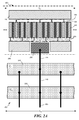
- a plurality of transistors 100 may be included in a power transistor 200 that is formed on a semiconductor die, as depicted in FIG. 2A .
- a plurality of source contacts 120, gate contacts 130, and drain contacts 140 may be formed in a linear array on an underlying gallium-nitride material layer.
- the number of source, gate, and drain contacts in the array may determine a length L d of an active region of the power transistor.
- the length L d of the active region may be between approximately 1 mm and approximately 50 mm, according to some embodiments. Increasing the number of source, drain, and gate contacts increases, approximately linearly, the amount of power the power transistor may handle.
- a power density rating per unit length of a power transistor may be specified in terms of a periphery value that is approximately equal to the product of a number of gates used in the transistor and their corresponding gate width W g .
- a power density rating for a transistor of the present embodiments is between approximately 1 Watt per millimeter (W/mm) and approximately 15 W/mm where length is in terms of the periphery value.
- a power transistor may further be defined in terms of the drain voltage V DD applied to the transistor.
- a power transistor may be designed to safely operate at V DD between 0 V and approximately 28 V.
- a power transistor may be designed to safely operate at V DD between 0 V and approximately 50 V.
- a power transistor may be designed to operate safely at V DD ⁇ 50 V or more.
- a power density rating per unit length of a power transistor may be specified in terms of a periphery value and the operating drain voltage applied to power transistor.
- the interconnects 270 may be patterned over the substrate 105 that connect the gate, source, and drain contacts to corresponding gate pads 255, source pads 250, and drain pads 260 located on the die.
- the interconnects 270 may be formed on multiple levels. There may be a plurality of gate pads, source pads, and drain pads formed along a length of the power transistor adjacent to the gate, source, and drain contacts of the individual transistors.
- the gate pads, source pads, and drain pads may be sized to permit wire bonding to other circuit components. For example, the pads may be at least 20 microns in length on a side.
- the pads, interconnects, and contacts may comprise metal ( e.g. gold, copper, aluminum) or a combination of metals.
- a thin adhesion layer (e.g ., titanium or chrome) may be deposited on a layer before depositing a more conductive material, such as gold, copper, nickel, or aluminum, for a pad.
- the electrodes may be connected to conductive elements.
- the source electrodes, drain electrodes and/or gate electrodes may be connected to field plates.
- the pads or electrodes may be connected electrically to through-wafer conductive vias, for example, to connect the source of the transistor to ground through a conductive source via and back-metal layer formed on the backside of the substrate.
- a packaged power transistor may include a plurality of bond wires 225 connected to the gate pads, as depicted in FIG. 2A . There may be additional bond wires connected to source pads and drain pads. There may be more than one bond wire connected to a pad. For example, there may be a plurality of bond wires 264 connected to drain pad 260 and spaced apart on a regular pitch, as illustrated in FIG. 2B . In some cases, the bond wires may be spaced on an irregular pitch. The pitch of bond wires connected to the pads may be between approximately 100 microns and approximately 0.5 mm. The pitch of bond wires connecting to the gate pads may be the same as or different than the pitches of bond wires connecting to the source and drain pads.
- the bond wires may comprise gold or any other suitable metal, and may provide electrical connection to a corresponding source, drain, or gate lead of a package in which the power transistor is housed.
- the bond wires may be connected to the bond pads using a ball bond or wedge bond for example.
- ribbon bonds may be used instead of, or in addition to, bond wires.
- a packaged power transistor 206 may include a power transistor 200 and an input matching network 202 that is configured to transform impedance at a fundamental operating frequency of the power transistor and to reduce or terminate power at the second harmonic of the fundamental frequency.
- a packaged power transistor 206 may be tuned via adjusting components of the input matching network for a particular operating frequency.
- An operating frequency may be between approximately 500 MHz and approximately 6 GHz, according to some implementations, or may be between approximately 1 GHz and approximately 6 GHz.
- an input matching network 202 may comprise a second capacitor C 2 220 and first capacitor C 1 210 connected to gate pads 255 of the power transistor 200, as depicted in FIGS. 2A-2B .
- the capacitors may comprise integrated capacitors formed on silicon.
- the capacitors may comprise integrated capacitors formed on gallium-arsenide. Radiofrequency signals (or other high-frequency signals) applied to a gate terminal 211 of the packaged power transistor 206 may couple to the gate pads 255 via the first and second capacitors and interconnecting bond wires.
- additional components may be included in the input matching network (e.g ., integrated passive devices). Additionally, parasitic impedance from the package materials and geometry of the package and component lay-out may affect and contribute to the input matching network 202.
- bond wires 215, with associated inductance that connect an electrode of the second capacitor 220 to an electrode of the first capacitor 210.
- bond wires 205 that connect the second capacitor 220 to an input terminal of the power transistor package (e.g., to a gate lead or pin).
- the pitch of bond wires 225 connecting to the gate pads may be the same as or different than the pitch of bond wires 215 connecting the two capacitors and the pitch of bond wires 205 connecting the second capacitor to a package lead.
- FIG. 2A shows only a portion of a power transistor, according to some embodiments.
- the power transistor may extend farther along the length direction L d than illustrated.
- the illustrated structure may be repeated.
- the first and second capacitors may extend farther than is illustrated, alongside the gate and source pads of the device.
- the length of the capacitors may be greater than, approximately equal to, or less than the length L d of the transistor's active region.
- the capacitance of the first and second capacitors 210, 220 is approximately linearly proportional to the active region length L d .
- the capacitance per unit length (in the direction of L d ) of the first capacitor may be between approximately 1 picofarad/mm (pF/mm) and approximately 10 pF/mm, according to some embodiments.
- the capacitance per unit length of the second capacitor may be between approximately 1 pF/mm and approximately 20 pF/mm, according to some embodiments.
- a value of the first capacitor 210 may be between approximately 5 pF and approximately 60 pF.
- a value of the second capacitor 220 may be between approximately 5 pF and approximately 60 pF.
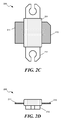
- FIG. 2B depicts a cut-away view of a packaged power transistor 206, according to some embodiments.
- the second capacitor 220 may connect via bond wires 205 to a first fin-shaped gate input terminal 211 of the power transistor, according to some embodiments.
- a conductive mount 212 may serve as a source contact and connect to source pads 250 via bond wires or conductive through-wafer source vias (not shown).
- the drain pad 260 may connect via bond wires 264 to a drain terminal 213 of the packaged power transistor 206.
- the drain terminal may also be fin shaped.
- a packaged power transistor 206 may further include an output matching network (not shown) connected between one or more drain pads260 and the drain terminal 213.
- An output matching network may comprise a shunt capacitor and bond wires or ribbon bonds connecting an electrode of the capacitor to the drain pads 260 and drain terminal.
- the die comprising the power transistor 200 and the two-capacitor input matching network may be packaged in a metal-ceramic enclosure 204, according to some embodiments.
- the enclosure 204 may comprise plastic, or the packaging may comprise a plastic overmold enclosure.
- a package may comprise a ceramic air-cavity, a plastic air-cavity, or plastic over-mold package.
- FIGS. 2C-2D depict additional views of a packaged power transistor 206, according to some embodiments. It is noted that although FIG. 2C represents one exemplary embodiment of the present invention, other packaged configurations consisting of two or more gallium-nitride-based transistors 200, each with their corresponding matching networks 202 (elements 210, 220 and bond wires), may be implemented to scale a packaged product to higher output power levels.
- a packaged power transistor 206 may be tuned for a desired application by adjusting components of the input matching network 202 (e.g., by selecting capacitance values for at least the first and second capacitors C 1 and C 2 ).
- an application may have a desired or target operating frequency or frequency range (e.g., a carrier frequency for wireless communications or radar) and a target operating power. Achieving a target power may comprise selecting an active region length L d and/or individual transistor gate width W g .
- a target operating power may be met by assembling plural packaged power transistors 206 onto a same device board. For example, a plurality of power transistors (packaged or unpackaged) may be assembled on a same circuit board and configured to operate in parallel on an input signal as a single power transistor.
- a packaged power transistor 206 can be tuned for a target operating frequency using a two-stage process in which the values of the first and second capacitors C 1 , C 2 are tuned separately.
- the tuning process may be performed with the assistance of numerical simulation or using empirical methods.
- tuning may be implemented using a software tool such as Advanced Design System (ADS) available from Keysight Technologies, Inc. of Santa Rosa, California.
- ADS Advanced Design System
- suitable software tools include, but are not limited to NI AWR Design Environment available from AWR Corporation of El Segundo, California and Sonnet® software tools available from Sonnet Software of North Syracuse, New York.
- the tuning procedure may be iterated before selecting values of capacitances for the first and second capacitors.
- a scattering-parameter S 11 curve for a portion of the transistor and input matching network is determined over a range of frequencies that span a target operating frequency or operating frequency range for the transistor.
- a first capacitive shunt comprising the first capacitor C 1 is connected to at least one gate pad 255 of the transistor 200, but the second capacitor C 2 is absent or not yet connected.
- the gate-to-source capacitance C gs is included when determining the S 11 curve.
- an input signal may be applied to a gate lead of the packaged device and the frequency swept over any range between about 0.5 GHz and about 10 GHz.
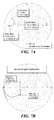
- the S 11 scattering-parameter curve 310 of the resulting circuit may then be determined and plotted on a Smith chart 300, as depicted in FIG. 3A .
- the S 11 parameter represents an amount of a signal applied to an input port (e.g., the first capacitive shunt or a gate lead of the packaged transistor) that is reflected or coupled back from the power transistor.
- a crude circuit model for the portion of the power transistor used for the first stage of design may include elements as configured in the circuit 350 of FIG. 3B .
- a first capacitive shunt comprising capacitor C 1 is connected to at least one gate pad 255.
- Additional elements may be included in a full circuit model (e.g ., inductance due to bond wires between the RF input and gate of transistor M1, parasitic capacitances between gate and source and gate and drain of transistor M1, parasitic package impedance, etc .).
- S 11 parameter values over a range of trial frequencies may be computed numerically from a full circuit model for several capacitance values C 1 .
- a gate bias voltage V GS may be applied to the gate terminal of power transistor to bias the transistor at its targeted quiescent operating point.
- An S 11 310 curve for a trial capacitive value may exhibit a resonance loop 320, as shown in the Smith chart of FIG. 3A .
- the value of the first capacitor C 1 and/or one or more structural aspects of the bond wires 225 may be altered while the location of the resonance loop 320 is tracked.
- the inventors have found that changing the value of the first capacitor and/or changing aspects of the bond wires can change the location in frequency of the resonance loop 320.
- the inventors have recognized and appreciated that a packaged power transistor 206 will exhibit improved drain efficiency (by up to 10% increase or more) when a peak of the resonance loop is located at approximately twice the target frequency of the power transistor.
- a target frequency is indicated by the "O" symbols in FIG. 3A
- twice the target frequency is indicated by the "X” symbols.
- the value of the first capacitor C 1 may be adjusted until the resonant loop peak moves to approximately twice the target frequency of the packaged power transistor 206. Adjusting the value of capacitor C 1 may move the resonance peak to a higher frequency, as depicted by the second S 11 curve 312. For example, if a target frequency for a power transistor is 2.5 GHz, then the value of the first capacitor C 1 may be adjusted until the resonant loop peak is located at approximately 5 GHz.
- a target frequency for which a transistor and input matching network is tuned may be a target operating frequency for the final packaged device.
- a target frequency may be a frequency value at an upper limit of a specified frequency range over which the packaged device is to operate.
- a second capacitive shunt including the second capacitor C 2 is included in the input network, and the determination of S 11 repeated.
- the value of C 2 may be adjusted to obtain a desired matching input impedance of the packaged power transistor at the target frequency.
- other elements affecting impedance between the gate lead of the packaged transistor and first capacitive shunt may also be adjusted.
- Other elements may include bond wires ( e.g ., changing a number of bond wires), integrated passive devices, and package geometry and/or material.
- an application may require an input impedance of the packaged transistor to be 10 ohms. Accordingly, the second capacitor and other elements may be adjusted until the corresponding S 11 curve 412 shows an input impedance of approximately 10 ohms at the fundamental or target frequency, as depicted in FIG. 4A .
- a crude circuit model for the packaged power transistor used for the second stage of design may include elements as configured in the circuit 450 of FIG. 4B .
- a second capacitive shunt including the second capacitor C 2 may be connected to the first capacitive shunt.
- the circuit model does not show inductances associated with bond wires, parasitic capacitances, or parasitic impedances, which may be included in a full circuit model of the input matching network.
- one or more iterations of adjusting capacitance values in the first tuning stage and second tuning stage may be employed to better position the resonance loop and match input impedance of a packaged power transistor 206.
- the second capacitor may remain connected to the input network.
- capacitances and other values may be adjusted to obtain a targeted real input impedance.
- the targeted input impedance may be between 0 ohms and approximately 100 ohms.
- An input impedance may be matched to within ⁇ 10 %, according to some embodiments.
- FIG. 5 depicts a flow chart of acts associated with a method 500 for tuning a packaged power transistor, according to some embodiments.
- a method of tuning the amplifier may comprise determining (step 510) a target frequency for a power transistor.
- a customer may specify a target frequency for a particular application.
- a particular application may require a target frequency to lie within a certain range (e.g., to meet wireless communication protocols).
- a designer may determine the target frequency based upon the needs of a particular application.
- a method 500 may further comprise acts of varying (step 520) values of a capacitor C 1 in a first capacitive shunt connected to at least one gate contact of the power transistor while determining S 11 curves for the circuit without the second capacitor C 2 present.
- C 1 may be varied until a resonance loop of the S 11 curve is located at approximately twice the target frequency determined in step 510.
- a second capacitive shunt including the second capacitor C 2 may be added (step 530) to the input matching network (e.g., connected to the first capacitive shunt).
- the method 500 may further include varying (step 540) the value of the second capacitor C 2 to impedance match the input of the packaged power transistor.
- Step 540 may comprise varying C 1 while determining S 11 curves for the circuit, from which an input impedance can be determined.
- the desired input impedance may be selected for a particular application. For example, a customer may specify an output impedance of a device that will drive the power transistor, and a designer may match the input impedance to the specified output impedance.
- the input impedance may be selected to be a common value, e.g., 50 ohms.
- a method may comprise determining (step 545) whether it is necessary to iterate the tuning process. If it is determined that tuning needs to be iterated, at least the act of varying (step 520) the first capacitor C 1 may be repeated while C 2 is connected. In some case, the act of varying (step 540) the second capacitance may also be repeated.
- a method 500 for tuning a packaged power transistor may comprise selecting the values for the two input capacitors C 1 and C 2 that provide an S 11 resonance loop at approximately twice the target frequency (without C 2 present in the circuit), and transform the input impedance of the packaged transistor to a desired matching impedance (by adding a second capacitive shunt with capacitor C 2 ).
- a plurality of packaged power transistors may then be fabricated with the selected values of input capacitances.
- tuning the input network of a power transistor as described above can increase the drain efficiency of the packaged transistor appreciably.
- the tuning can yield drain efficiencies between 50% and 55% in some embodiments, between 55% and 60% in some embodiments, between 60% and 65% in some embodiments, and yet between 65% and 75% in some embodiments.
- the tuning can provide peak drain efficiencies between approximately 65% and approximately 80% at frequencies up to approximately 3.8 GHz.
- tuning the input network can provide peak drain efficiencies between approximately 65% and approximately 80% at frequencies up to approximately 6 GHz.
- Some embodiments may include heterojunction transistors comprising SiC, SiGe, GaAs, InP, and CdTe.
- This example illustrates a tuning process for one embodiment of a gallium-nitride power transistor.
- the transistor package was similar to that depicted in FIG. 2B , and the periphery value for the active region of the transistor was approximately 24.2 mm. Twelve bond wires were connected between gate pads 255 of the transistor and a first capacitor C 1 of a first capacitive shunt. The first capacitive shunt was located off die, but within the transistor package. The bond wires were spaced on a pitch of approximately 380 microns. The bond wires were gold having a diameter of approximately 25 microns.
- the capacitor C 1 was adjusted to locate the resonance loop peak 320 of the S 11 curve at approximately 5300 MHz, as depicted in FIG. 6A .
- the gate-to-source capacitance C gs was included in the model. The value of capacitor C 1 was selected to be 20 pF.
- the source-terminal impedance curve (which provides a measure of impedance looking from the source terminal 212 thru the gate pads 255 toward the gate lead)of the power transistor, looking back into the first capacitive shunt, was determined during the first stage of tuning.
- a source-terminal impedance curve is shown in FIG. 6B .
- the combination of C gs . bond wires, capacitor and package for this example provide a source-terminal impedance that is near zero ohms (short) at 5.3 GHz, the second harmonic of the target frequency.
- a second capacitive shunt including the second capacitor C 2 was added to the input network and the S 11 curve determined again as the capacitance of C 2 was varied.
- a desired impedance of approximately 5 ohms was found at the fundamental frequency when C 2 was selected to be 20 pF, as depicted in FIG. 7A .
- the source-terminal impedance curve (which provides a measure of impedance looking from the source terminal 212 through the gate pads 255 toward the gate lead) was determined for the two-capacitor network, and is shown in FIG. 7B .
- the curve shows a near-zero impedance (short) at approximately the second harmonic frequency.
- the inventors have found that such a low impedance at the second harmonic implies that the packaged transistor will provide improved drain efficiency at the fundamental operating frequency.
- the drain efficiency increased from about 63 % to about 70 % with the tuned two-capacitor input network.
- the terms “approximately” and “about” may be used to mean within ⁇ 20% of a target dimension in some embodiments, within ⁇ 10% of a target dimension in some embodiments, within ⁇ 5% of a target dimension in some embodiments, and yet within ⁇ 2% of a target dimension in some embodiments.
- the terms “approximately” and “about” may include the target dimension.
- the technology described herein may be embodied as a method, of which at least some acts have been described.
- the acts performed as part of the method may be ordered in any suitable way. Accordingly, embodiments may be constructed in which acts are performed in an order different than described, which may include performing some acts simultaneously, even though described as sequential acts in illustrative embodiments. Additionally, a method may include more acts than those described, in some embodiments, and fewer acts than those described in other embodiments.
Abstract
Description
- The technology relates to high-speed, high-power semiconductor transistors and amplifiers constructed from such transistors.
- Gallium nitride semiconductor material has received appreciable attention in recent years because of its desirable electronic and electro-optical properties. GaN has a wide, direct bandgap of about 3.4 eV that corresponds to the blue wavelength region of the visible spectrum. Light-emitting diodes (LEDs) and laser diodes (LDs) based on GaN and its alloys have been developed and are commercially available. These devices can emit visible light ranging from the violet to red regions of the visible spectrum.
- Because of its wide bandgap, GaN is more resistant to avalanche breakdown and can maintain electrical performance at higher temperatures than other semiconductors, such as silicon. GaN also has a higher carrier saturation velocity compared to silicon. Additionally, GaN has a Wurtzite crystal structure, is a very stable and hard material, has a high thermal conductivity, and has a much higher melting point than other conventional semiconductors such as silicon, germanium, and gallium arsenide. Accordingly, GaN is useful for high-speed, high-voltage, and high-power applications. For example, gallium-nitride materials are useful in semiconductor amplifiers for radiofrequency (RF) communications, radar, RF energy, and microwave applications.
- Applications supporting mobile communications and wireless internet access under current and proposed communication standards, such as WiMax, 4G, and 5G, can place austere performance demands on RF power transistors. These transistors may need to meet performance specifications related to output power, signal linearity, signal gain, bandwidth and efficiency.
- Methods and structures for improving the performance of high-speed, high-power, semiconductor transistors are described. The transistors may comprise gallium-nitride material in some embodiments, though other semiconductor materials may be used on other embodiments. In some implementations, the transistors may be formed from one or more layers of gallium nitride semiconductor material deposited on a substrate of a different material. On-chip circuitry may be included to tune the performance of the device to suppress second harmonic generation and match an input impedance of the device. According to some embodiments, a two-capacitor input network is incorporated into a transistor package to improve the performance of the device.
- In some embodiments, a method for tuning a semiconductor transistor having a two-capacitor input network may comprise acts of altering a value of a first capacitor in a first capacitive shunt until a resonance loop of an S11 scattering-parameter curve for the transistor has a peak at a frequency that is approximately twice a target frequency for the semiconductor transistor. The first capacitive shunt may be connected to at least one gate contact of the semiconductor transistor. A method for tuning the semiconductor transistor may further include altering a value of a second capacitor in a second capacitive shunt until an input impedance at an input to the second capacitive shunt is approximately equal to a target impedance value. The second capacitive shunt may be added to the first capacitive shunt after the value of the first capacitor has been altered.
- In some aspects, the semiconductor transistor may comprise gallium nitride in an active region of the transistor. The target frequency may be between approximately 1 GHz and approximately 6 GHz. According to some implementations, altering the value of the first capacitor may comprise selecting a value of the first capacitor in a range between approximately 5 pF and approximately 60 pF. In some aspects, altering the value of the second capacitor may comprise selecting a value of the second capacitor in a range between approximately 10 pF and approximately 50 pF.
- According to some implementations, the S11 scattering-parameter curve is determined looking into the first capacitive shunt toward the semiconductor transistor. In some aspects, the S11 scattering-parameter curve is determined by numerical simulation. In some implementations, the S11 scattering-parameter curve includes the effect of gate-to-source capacitance Cgs.
- According to some implementations, a method for tuning a semiconductor transistor may further include connecting an electrode of the first capacitor to gate pads of the semiconductor transistor with a plurality of bond wire connections. In some aspects, the first capacitor is a bar capacitor. In some implementations, a method further includes connecting an electrode of the second capacitor to an electrode of the first capacitor with a plurality of bond wires. A method may also include connecting the electrode of the second capacitor to a package gate lead. In some aspects, the second capacitor is a bar capacitor. A method for tuning a semiconductor transistor may further include acts of selecting a first value for the first capacitor, selecting a second value for the second capacitor, and assembling the semiconductor transistor in a package with a first capacitor having the first value and a second capacitor having the second value.
- In some implementations, a target impedance value for a tuned semiconductor transistor includes between 0 ohms and 100 ohms of real impedance. In some aspects, the semiconductor transistor comprises one or more depletion-mode transistors disposed in a linear array on a semiconductor die.
- The foregoing implementations, features, and aspects may be included in an embodiment of a method for tuning a semiconductor transistor in any suitable combination.
- In some embodiments, a tuned semiconductor transistor may comprise a first capacitive shunt connected to at least one gate contact of the semiconductor transistor and a second capacitive shunt connected to the first capacitive shunt, wherein a peak of a resonance loop for an S11 scattering-parameter curve determined at the first capacitive shunt looking toward the semiconductor transistor and with the second capacitive shunt disconnected is at a frequency that is approximately twice a target frequency for the semiconductor transistor.
- In some aspects, the semiconductor transistor comprises one or more gallium-nitride transistors integrated onto a die. The one or more gallium-nitride transistors may be arranged in a linear array. In some cases, the one or more gallium-nitride transistors comprise depletion-mode transistors. According to some aspects, the one or more gallium-nitride transistors comprise high-electron-mobility transistors. In some implementations, the one or more gallium-nitride transistors are arranged in a linear array and a power density rating per unit length for the semiconductor transistor is between approximately 1 W/mm and approximately 15 W/mm. In some aspects, the one or more gallium-nitride transistors include a gallium-nitride layer formed over a silicon substrate. According to some implementations, a drain efficiency at the target frequency for a tuned semiconductor transistor is between approximately 50 % and approximately 80%.
- In some implementations, a tuned semiconductor transistor may comprise at least one transition layer formed between the silicon substrate and the gallium-nitride layer. In some aspects, the first capacitive shunt may comprise a first bar capacitor having a capacitance between approximately 5 pF and approximately 60 pF and a first plurality of bond wires connected between an electrode of the first bar capacitor and gate pads of the one or more transistors. The bond wires may be formed of gold and may be spaced between approximately 100 microns and approximately 500 microns apart. In some cases, the second capacitive shunt comprises a second bar capacitor having a capacitance between approximately 5 pF and approximately 60 pF and a second plurality of bond wires connected between an electrode of the second bar capacitor and an electrode of the first bar capacitor. The first and second plurality of bond wires may be formed of gold and may be spaced between approximately 100 microns and approximately 500 microns apart.
- According to some aspects, a tuned semiconductor transistor may further comprise a package housing the semiconductor transistor and the first and second capacitive shunts. The package may include a metal lead connected to the second capacitive shunt that provides a gate connection to the at least one gate contact of the transistor. In some implementations, the package may comprise a ceramic air-cavity, a plastic air-cavity, or plastic over-mold package. In some aspects, a real input impedance for the semiconductor transistor is between 0 ohms and approximately 100 ohms. A target frequency for the transistor may be between approximately 1 GHz and approximately 6 GHz. In some cases, a plurality of tuned semiconductor transistors may be assembled on a circuit board to operate in parallel as a single power transistor.
- The foregoing apparatus and method embodiments may be included in any suitable combination with aspects, features, and acts described above or in further detail below. These and other aspects, embodiments, and features of the present teachings can be more fully understood from the following description in conjunction with the accompanying drawings.
- The skilled artisan will understand that the figures, described herein, are for illustration purposes only. It is to be understood that in some instances various aspects of the embodiments may be shown exaggerated or enlarged to facilitate an understanding of the embodiments. The drawings are not necessarily to scale, emphasis instead being placed upon illustrating the principles of the teachings. In the drawings, like reference characters generally refer to like features, functionally similar and/or structurally similar elements throughout the various figures. Where the drawings relate to microfabricated circuits, only one device and/or circuit may be shown to simplify the drawings. In practice, a large number of devices or circuits may be fabricated in parallel across a large area of a substrate or entire substrate. Additionally, a depicted device or circuit may be integrated within a larger circuit.
- When referring to the drawings in the following detailed description, spatial references "top," "bottom," "upper," "lower," "vertical," "horizontal," and the like may be used. Such references are used for teaching purposes, and are not intended as absolute references for embodied devices. An embodied device may be oriented spatially in any suitable manner that may be different from the orientations shown in the drawings. The drawings are not intended to limit the scope of the present teachings in any way.
-
FIG. 1A is an elevation view of structure of a field-effect transistor comprising gallium-nitride material, according to some embodiments; -
FIG. 1B depicts a plan view of a field-effect transistor comprising gallium-nitride material, according to some embodiments; -
FIG. 2A depicts a plan view of a power transistor comprising gallium nitride material, according to some embodiments; -
FIG. 2B is a cut-away plan view depiction of a packaged power transistor comprising gallium nitride material, according to some embodiments; -
FIG. 2C depicts a plan view of a packaged power transistor, according to some embodiments; -
FIG. 2D depicts an end-on elevation view of a packaged power transistor, according to some embodiments; -
FIG. 3A is a Smith chart illustrating second-harmonic tuning curves for a semiconductor transistor, according to some embodiments; -
FIG. 3B is a crude circuit schematic showing an input network and semiconductor transistor corresponding to the tuning curve ofFIG. 3A , according to some embodiments; -
FIG. 4A is a Smith chart illustrating an impedance-matching curve for a power transistor, according to some embodiments; -
FIG. 4B is a circuit schematic showing a two capacitor input network for a transistor corresponding to the tuning curve ofFIG. 4A , according to some embodiments; -
FIG. 5 depicts a method for tuning a power transistor, according to some embodiments; -
FIG. 6A shows an example of the gate terminal input impedance trajectory as seen from outside the package looking into the gate lead of the device for a gallium-nitride transistor during a first stage of tuning; -
FIG. 6B shows an impedance trajectory as seen from a GaNFET source terminal 212 up thru thegate pad 255 of the FET to the single capacitor network with packaged device gate terminal terminated into a 50 ohm load; -
FIG. 7A shows an example of thegate terminal 211 input impedance trajectory as seen from outside the package looking into the gate lead of the device for a gallium-nitride transistor during a second stage of tuning; and -
FIG. 7B shows an impedance trajectory as seen from the GaNFET source terminal 212 up thru thegate pad 255 of the FET to the double capacitor network with packaged device gate terminal terminated into a 50 ohm load. - Features and advantages of the illustrated embodiments will become more apparent from the detailed description set forth below when taken in conjunction with the drawings.
- As described above, transistors comprising gallium nitride material are useful for high-speed, high-voltage, and high-power applications because of the favorable material properties of gallium nitride. Some of these applications can place demanding performance requirements on devices that include gallium-nitride transistors. The inventors have recognized and appreciated that proper second-harmonic termination at a transistor's input can increase the device's peak drain efficiency (DE) and potentially increase peak output power. Further, proper second-harmonic termination, via an input network can improve a transistor's usefulness for power amplifier architectures that include, but are not limited to, class-J, class-F, inverse class-F, class-AB, and Doherty amplifiers. The inventors have recognized and appreciated that an input network can be integrated in a package with the transistor, and a two-stage method may be used to better suppress second harmonic generation and match the device's input impedance to a target value.
- By way of introductory explanation,
FIG. 1A and FIG. 1B depict an example of a single field-effect transistor 100 that may be included in embodiments described below. A transistor may be formed from one or more gallium-nitride layers 114, 112 on asubstrate 105. Atransistor 100 may include one ormore source contacts 120, one ormore gate contacts 130, and one ormore drain contacts 140. One ormore passivation layers 150 may be deposited on the transistor. A width Wg of the gate may be between approximately 10 microns (μm) and approximately 2 millimeters (mm). A length of the channel Lg may be between approximately 0.02 μm and approximately 1.0 μm. - When using the terms "on," "adjacent," or "over" in to describe the locations of layers or structures, there may or may not be one or more layers of material between the described layer and an underlying layer that the layer is described as being on, adjacent to, or over. When a layer is described as being "directly" or "immediately" on, adjacent to, or over another layer, no intervening layer is present. When a layer is described as being "on" or "over" another layer or substrate, it may cover the entire layer or substrate, or a portion of the layer or substrate. The terms "on" and "over" are used for ease of explanation relative to the illustrations, and are not intended as absolute directional references. A device may be manufactured and implemented in other orientations than shown in the drawing (for example, rotated about a horizontal axis by more than 90 degrees.
- In some implementations, a
transistor 100 is formed as a depletion-mode, high-electron-mobility transistor (HEMT). In some embodiments, thetransistor 100 may be formed as a junction field-effect transistor (JFET). Other transistor architectures may be used in other embodiments. Other transistor architectures may include, but not be limited to, metal-oxide-semiconductor field-effect transistor (MOSFET) and metal-insulator-semiconductor field-effect transistor (MISFET). - According to some embodiments, the
substrate 105 may comprise bulk GaN, although bulk GaN can be expensive to manufacture. In preferred implementations, the substrate may comprise silicon. For example, the substrate may be a bulk monocrystalline silicon substrate or monocrystalline silicon-on-insulator (SOI). In some embodiments, thesubstrate 105 may comprise sapphire or silicon carbide. Thesubstrate 105 may be in the form of a wafer (e.g., a Si semiconductor wafer) and have a diameter between approximately 50 mm and approximately 450 mm. In various embodiments, the surface of the substrate is monocrystalline, so that III-nitride material may be epitaxially grown from the surface of the substrate. According to some embodiments, a silicon substrate may comprise a high resistivity silicon layer or region. As used herein, high resistivity is defined as greater than 100 ohm-cm, greater than 1000 ohm-cm or even greater than 10,000 ohm-cm. In other embodiments, the silicon substrate may be comprised of floatzone silicon (111), or comprised of magnetic Czochralski (MCZ) silicon (111). Thesubstrate 105 may be approximately 1-mm thick, less than 725 microns thick, less than 675 microns thick, less than 625 microns thick, less than approximately 150 microns thick, or less than approximately 50 microns thick. - Because of the lattice mismatch between the substrate and a gallium-nitride layer 114, one or more
transitional layers 112 may be formed on the substrate. Thetransitional layers 112 may include a buffer layer (e.g., AlN) deposited directly on or above thesubstrate 105 followed by one or more gallium nitride material layers deposited on the buffer layer. Examples oftransitional layers 112 are described in, for example,U. S. patent No. 7,135,720 andU. S. patent No. 9,064,775 - As used herein, the phrase "gallium nitride material" refers to gallium nitride (GaN) and any of its alloys, such as aluminum gallium nitride (AlxGa (1-x)N), indium gallium nitride (InyGa(1-y)N), aluminum indium gallium nitride (AlxInyGa(1-x-y)N), gallium arsenide phosporide nitride (GaAsxPy N(1-x-y)), aluminum indium gallium arsenide phosporide nitride (AlxInyGa(1-x-y)AsaPb N(1-a-b)), amongst others. Typically, when present, arsenic and/or phosphorous are at low concentrations (i.e., less than 5 percent by weight). In certain preferred embodiments, the gallium nitride material has a high concentration of gallium and includes little or no amounts of aluminum and/or indium. In high gallium concentration embodiments, the sum of (x+y) may be less than 0.4 in some implementations, less than 0.2 in some implementations, less than 0.1 in some implementations, or even less in other implementations. In some cases, it is preferable for at least one gallium nitride material layer to have a composition of GaN (i.e., x=y=a=b=0). For example, an active layer in which a transistor channel is formed may have a composition of GaN. Gallium nitride materials may be doped n-type or p-type, or may be intrinsic. Suitable gallium nitride materials are described in
U.S. patent No. 6,649,287 , which is incorporated herein by reference in its entirety. In some implementations, it is preferable for at least one gallium nitride layer to be comprised of one or more device layers, including for example, a channel layer, a barrier layer formed over the channel layer, a back barrier layer formed below the channel layer, a spacer layer or interlayer formed between the barrier layer and channel layer, and/or one or more capping layers formed over the barrier layer. It may be also preferred that the device layers form a high electron mobility transistor (HEMT) comprising a two dimensional electron gas (2DEG) and/or two dimension hole gas (2DHG) located at the interface regions of the barrier (backbarrier) and channel device layers. In some cases, the HEMT may be a depletion mode (normally ON) or enhancement mode (normally OFF) transistor. - According to some embodiments, a
transistor 100 comprises a gallium-nitride material layer 114 which includes source, channel, and drain regions below the source, gate, and drain contacts. Carrier transport between the source and drain in the gallium-nitride material layer 114 is controlled by voltage applied to thegate contact 130. Because the gallium-nitride material layer 114 includes the active region of the device, it may have a low defect density that is typical for integrated-circuit-grade GaN. For example the defect density may be less than approximately 109 cm-2 in some implementations, and less than approximately 108 cm-2 in some embodiments. Defect densities may be higher in thetransition layer 112. A thickness of the gallium-nitride material layer 114 may be between approximately 50 nm and approximately 1500 nm. In some implementations, gallium-nitride material layer 114 has a composition of GaN. - A plurality of
transistors 100, each like that illustrated inFIGS. 1A-1B , may be included in apower transistor 200 that is formed on a semiconductor die, as depicted inFIG. 2A . For example, a plurality ofsource contacts 120,gate contacts 130, anddrain contacts 140 may be formed in a linear array on an underlying gallium-nitride material layer. The number of source, gate, and drain contacts in the array may determine a length Ld of an active region of the power transistor. For example, the length Ld of the active region may be between approximately 1 mm and approximately 50 mm, according to some embodiments. Increasing the number of source, drain, and gate contacts increases, approximately linearly, the amount of power the power transistor may handle. Also, increasing a width of the gates Wg can increase an amount of power the device may handle. In some embodiments, a power density rating per unit length of a power transistor may be specified in terms of a periphery value that is approximately equal to the product of a number of gates used in the transistor and their corresponding gate width Wg. According to some implementations, a power density rating for a transistor of the present embodiments is between approximately 1 Watt per millimeter (W/mm) and approximately 15 W/mm where length is in terms of the periphery value. - In some cases, a power transistor may further be defined in terms of the drain voltage VDD applied to the transistor. For example, a power transistor may be designed to safely operate at VDD between 0 V and approximately 28 V. In some cases, a power transistor may be designed to safely operate at VDD between 0 V and approximately 50 V. In other cases, a power transistor may be designed to operate safely at VDD ∼ 50 V or more. In some embodiments, a power density rating per unit length of a power transistor may be specified in terms of a periphery value and the operating drain voltage applied to power transistor.
- There may be a number of
metal interconnects 270 patterned over thesubstrate 105 that connect the gate, source, and drain contacts tocorresponding gate pads 255,source pads 250, and drainpads 260 located on the die. Theinterconnects 270 may be formed on multiple levels. There may be a plurality of gate pads, source pads, and drain pads formed along a length of the power transistor adjacent to the gate, source, and drain contacts of the individual transistors. The gate pads, source pads, and drain pads may be sized to permit wire bonding to other circuit components. For example, the pads may be at least 20 microns in length on a side. The pads, interconnects, and contacts may comprise metal (e.g. gold, copper, aluminum) or a combination of metals. In some embodiments, a thin adhesion layer (e.g., titanium or chrome) may be deposited on a layer before depositing a more conductive material, such as gold, copper, nickel, or aluminum, for a pad. In some implementations, the electrodes may be connected to conductive elements. For example, the source electrodes, drain electrodes and/or gate electrodes may be connected to field plates. In addition, in some cases, the pads or electrodes may be connected electrically to through-wafer conductive vias, for example, to connect the source of the transistor to ground through a conductive source via and back-metal layer formed on the backside of the substrate. - A packaged power transistor may include a plurality of
bond wires 225 connected to the gate pads, as depicted inFIG. 2A . There may be additional bond wires connected to source pads and drain pads. There may be more than one bond wire connected to a pad. For example, there may be a plurality ofbond wires 264 connected to drainpad 260 and spaced apart on a regular pitch, as illustrated inFIG. 2B . In some cases, the bond wires may be spaced on an irregular pitch. The pitch of bond wires connected to the pads may be between approximately 100 microns and approximately 0.5 mm. The pitch of bond wires connecting to the gate pads may be the same as or different than the pitches of bond wires connecting to the source and drain pads. The bond wires may comprise gold or any other suitable metal, and may provide electrical connection to a corresponding source, drain, or gate lead of a package in which the power transistor is housed. In some implementations, the bond wires may be connected to the bond pads using a ball bond or wedge bond for example. In some cases, ribbon bonds may be used instead of, or in addition to, bond wires. - According to some embodiments, a packaged
power transistor 206 may include apower transistor 200 and aninput matching network 202 that is configured to transform impedance at a fundamental operating frequency of the power transistor and to reduce or terminate power at the second harmonic of the fundamental frequency. A packagedpower transistor 206 may be tuned via adjusting components of the input matching network for a particular operating frequency. An operating frequency may be between approximately 500 MHz and approximately 6 GHz, according to some implementations, or may be between approximately 1 GHz and approximately 6 GHz. - In some embodiments, an
input matching network 202 may comprise asecond capacitor C 2 220 andfirst capacitor C 1 210 connected togate pads 255 of thepower transistor 200, as depicted inFIGS. 2A-2B . In some implementations, the capacitors may comprise integrated capacitors formed on silicon. In some implementations, the capacitors may comprise integrated capacitors formed on gallium-arsenide. Radiofrequency signals (or other high-frequency signals) applied to agate terminal 211 of the packagedpower transistor 206 may couple to thegate pads 255 via the first and second capacitors and interconnecting bond wires. In some implementations, additional components may be included in the input matching network (e.g., integrated passive devices). Additionally, parasitic impedance from the package materials and geometry of the package and component lay-out may affect and contribute to theinput matching network 202. - There may be a plurality of
bond wires 215, with associated inductance, that connect an electrode of thesecond capacitor 220 to an electrode of thefirst capacitor 210. Additionally, there may be a plurality ofbond wires 205 that connect thesecond capacitor 220 to an input terminal of the power transistor package (e.g., to a gate lead or pin). The pitch ofbond wires 225 connecting to the gate pads may be the same as or different than the pitch ofbond wires 215 connecting the two capacitors and the pitch ofbond wires 205 connecting the second capacitor to a package lead. -
FIG. 2A shows only a portion of a power transistor, according to some embodiments. The power transistor may extend farther along the length direction Ld than illustrated. For example, the illustrated structure may be repeated. The first and second capacitors may extend farther than is illustrated, alongside the gate and source pads of the device. The length of the capacitors may be greater than, approximately equal to, or less than the length Ld of the transistor's active region. According to some implementations, the capacitance of the first andsecond capacitors first capacitor 210 may be between approximately 5 pF and approximately 60 pF. In some cases, a value of thesecond capacitor 220 may be between approximately 5 pF and approximately 60 pF. -
FIG. 2B depicts a cut-away view of a packagedpower transistor 206, according to some embodiments. Thesecond capacitor 220 may connect viabond wires 205 to a first fin-shapedgate input terminal 211 of the power transistor, according to some embodiments. Aconductive mount 212 may serve as a source contact and connect to sourcepads 250 via bond wires or conductive through-wafer source vias (not shown). Thedrain pad 260 may connect viabond wires 264 to adrain terminal 213 of the packagedpower transistor 206. The drain terminal may also be fin shaped. In some embodiments, a packagedpower transistor 206 may further include an output matching network (not shown) connected between one or more drain pads260 and thedrain terminal 213. An output matching network may comprise a shunt capacitor and bond wires or ribbon bonds connecting an electrode of the capacitor to thedrain pads 260 and drain terminal. The die comprising thepower transistor 200 and the two-capacitor input matching network may be packaged in a metal-ceramic enclosure 204, according to some embodiments. In some cases, theenclosure 204 may comprise plastic, or the packaging may comprise a plastic overmold enclosure. In some implementations, a package may comprise a ceramic air-cavity, a plastic air-cavity, or plastic over-mold package. -
FIGS. 2C-2D depict additional views of a packagedpower transistor 206, according to some embodiments. It is noted that althoughFIG. 2C represents one exemplary embodiment of the present invention, other packaged configurations consisting of two or more gallium-nitride-basedtransistors 200, each with their corresponding matching networks 202 (elements - As noted above, a packaged
power transistor 206 may be tuned for a desired application by adjusting components of the input matching network 202 (e.g., by selecting capacitance values for at least the first and second capacitors C1 and C2). In some embodiments, an application may have a desired or target operating frequency or frequency range (e.g., a carrier frequency for wireless communications or radar) and a target operating power. Achieving a target power may comprise selecting an active region length Ld and/or individual transistor gate width Wg. In some implementations, a target operating power may be met by assembling plural packagedpower transistors 206 onto a same device board. For example, a plurality of power transistors (packaged or unpackaged) may be assembled on a same circuit board and configured to operate in parallel on an input signal as a single power transistor. - The inventors have recognized and appreciated that a packaged
power transistor 206 can be tuned for a target operating frequency using a two-stage process in which the values of the first and second capacitors C1, C2 are tuned separately. The tuning process may be performed with the assistance of numerical simulation or using empirical methods. For example, tuning may be implemented using a software tool such as Advanced Design System (ADS) available from Keysight Technologies, Inc. of Santa Rosa, California. Other suitable software tools include, but are not limited to NI AWR Design Environment available from AWR Corporation of El Segundo, California and Sonnet® software tools available from Sonnet Software of North Syracuse, New York. In some cases, the tuning procedure may be iterated before selecting values of capacitances for the first and second capacitors. - In a first stage of design, a scattering-parameter S11 curve for a portion of the transistor and input matching network is determined over a range of frequencies that span a target operating frequency or operating frequency range for the transistor. In this first stage, a first capacitive shunt comprising the first capacitor C1 is connected to at least one
gate pad 255 of thetransistor 200, but the second capacitor C2 is absent or not yet connected. Additionally, the gate-to-source capacitance C gs is included when determining the S11 curve. As an example, an input signal may be applied to a gate lead of the packaged device and the frequency swept over any range between about 0.5 GHz and about 10 GHz. The S11 scattering-parameter curve 310 of the resulting circuit may then be determined and plotted on aSmith chart 300, as depicted inFIG. 3A . The S11 parameter represents an amount of a signal applied to an input port (e.g., the first capacitive shunt or a gate lead of the packaged transistor) that is reflected or coupled back from the power transistor. - For purposes of explanation, a crude circuit model for the portion of the power transistor used for the first stage of design may include elements as configured in the
circuit 350 ofFIG. 3B . A first capacitive shunt comprising capacitor C1 is connected to at least onegate pad 255. Additional elements may be included in a full circuit model (e.g., inductance due to bond wires between the RF input and gate of transistor M1, parasitic capacitances between gate and source and gate and drain of transistor M1, parasitic package impedance, etc.). In some implementations, S11 parameter values over a range of trial frequencies may be computed numerically from a full circuit model for several capacitance values C1. When determining S11, a gate bias voltage VGS may be applied to the gate terminal of power transistor to bias the transistor at its targeted quiescent operating point. - An
S 11 310 curve for a trial capacitive value may exhibit aresonance loop 320, as shown in the Smith chart ofFIG. 3A . To tune the amplifier to a target frequency, the value of the first capacitor C1 and/or one or more structural aspects of the bond wires 225 (number, size, length, material, spacing, straightness) may be altered while the location of theresonance loop 320 is tracked. The inventors have found that changing the value of the first capacitor and/or changing aspects of the bond wires can change the location in frequency of theresonance loop 320. The inventors have recognized and appreciated that a packagedpower transistor 206 will exhibit improved drain efficiency (by up to 10% increase or more) when a peak of the resonance loop is located at approximately twice the target frequency of the power transistor. A target frequency is indicated by the "O" symbols inFIG. 3A , and twice the target frequency is indicated by the "X" symbols. Accordingly, the value of the first capacitor C1 may be adjusted until the resonant loop peak moves to approximately twice the target frequency of the packagedpower transistor 206. Adjusting the value of capacitor C1 may move the resonance peak to a higher frequency, as depicted by the second S11 curve 312. For example, if a target frequency for a power transistor is 2.5 GHz, then the value of the first capacitor C1 may be adjusted until the resonant loop peak is located at approximately 5 GHz. - In some embodiments, a target frequency for which a transistor and input matching network is tuned may be a target operating frequency for the final packaged device. In some implementations, a target frequency may be a frequency value at an upper limit of a specified frequency range over which the packaged device is to operate.
- In a second stage of tuning, a second capacitive shunt including the second capacitor C2 is included in the input network, and the determination of S11 repeated. The value of C2 may be adjusted to obtain a desired matching input impedance of the packaged power transistor at the target frequency. In some implementations, other elements affecting impedance between the gate lead of the packaged transistor and first capacitive shunt may also be adjusted. Other elements may include bond wires (e.g., changing a number of bond wires), integrated passive devices, and package geometry and/or material.
- As just one example, an application may require an input impedance of the packaged transistor to be 10 ohms. Accordingly, the second capacitor and other elements may be adjusted until the corresponding S11 curve 412 shows an input impedance of approximately 10 ohms at the fundamental or target frequency, as depicted in
FIG. 4A . A crude circuit model for the packaged power transistor used for the second stage of design may include elements as configured in thecircuit 450 ofFIG. 4B . A second capacitive shunt including the second capacitor C2 may be connected to the first capacitive shunt. The circuit model does not show inductances associated with bond wires, parasitic capacitances, or parasitic impedances, which may be included in a full circuit model of the input matching network. - According to some embodiments, one or more iterations of adjusting capacitance values in the first tuning stage and second tuning stage may be employed to better position the resonance loop and match input impedance of a packaged
power transistor 206. During an iteration, the second capacitor may remain connected to the input network. In some cases, capacitances and other values may be adjusted to obtain a targeted real input impedance. The targeted input impedance may be between 0 ohms and approximately 100 ohms. An input impedance may be matched to within ± 10 %, according to some embodiments. -
FIG. 5 depicts a flow chart of acts associated with amethod 500 for tuning a packaged power transistor, according to some embodiments. A method of tuning the amplifier may comprise determining (step 510) a target frequency for a power transistor. In some implementations, a customer may specify a target frequency for a particular application. In some cases, a particular application may require a target frequency to lie within a certain range (e.g., to meet wireless communication protocols). A designer may determine the target frequency based upon the needs of a particular application. - A
method 500 may further comprise acts of varying (step 520) values of a capacitor C1 in a first capacitive shunt connected to at least one gate contact of the power transistor while determining S11 curves for the circuit without the second capacitor C2 present. C1 may be varied until a resonance loop of the S11 curve is located at approximately twice the target frequency determined instep 510. Subsequently, a second capacitive shunt including the second capacitor C2 may be added (step 530) to the input matching network (e.g., connected to the first capacitive shunt). - The
method 500 may further include varying (step 540) the value of the second capacitor C2 to impedance match the input of the packaged power transistor. Step 540 may comprise varying C1 while determining S11 curves for the circuit, from which an input impedance can be determined. In some embodiments, the desired input impedance may be selected for a particular application. For example, a customer may specify an output impedance of a device that will drive the power transistor, and a designer may match the input impedance to the specified output impedance. In some implementations, the input impedance may be selected to be a common value, e.g., 50 ohms. - In some implementations, a method may comprise determining (step 545) whether it is necessary to iterate the tuning process. If it is determined that tuning needs to be iterated, at least the act of varying (step 520) the first capacitor C1 may be repeated while C2 is connected. In some case, the act of varying (step 540) the second capacitance may also be repeated.
- According to some embodiments, a
method 500 for tuning a packaged power transistor may comprise selecting the values for the two input capacitors C1 and C2 that provide an S11 resonance loop at approximately twice the target frequency (without C2 present in the circuit), and transform the input impedance of the packaged transistor to a desired matching impedance (by adding a second capacitive shunt with capacitor C2). A plurality of packaged power transistors may then be fabricated with the selected values of input capacitances. - The inventors have recognized and appreciated that tuning the input network of a power transistor as described above can increase the drain efficiency of the packaged transistor appreciably. For example, the tuning can yield drain efficiencies between 50% and 55% in some embodiments, between 55% and 60% in some embodiments, between 60% and 65% in some embodiments, and yet between 65% and 75% in some embodiments. In some cases, the tuning can provide peak drain efficiencies between approximately 65% and approximately 80% at frequencies up to approximately 3.8 GHz. In some embodiments, tuning the input network can provide peak drain efficiencies between approximately 65% and approximately 80% at frequencies up to approximately 6 GHz.
- Although the above structures, circuits, and methods have been described primarily for gallium-nitride transistors, other semiconductor materials may be used in other embodiments of high-speed transistors. Some embodiments may include heterojunction transistors comprising SiC, SiGe, GaAs, InP, and CdTe.
- This example illustrates a tuning process for one embodiment of a gallium-nitride power transistor. The transistor package was similar to that depicted in
FIG. 2B , and the periphery value for the active region of the transistor was approximately 24.2 mm. Twelve bond wires were connected betweengate pads 255 of the transistor and a first capacitor C1 of a first capacitive shunt. The first capacitive shunt was located off die, but within the transistor package. The bond wires were spaced on a pitch of approximately 380 microns. The bond wires were gold having a diameter of approximately 25 microns. In the first stage of tuning, the capacitor C1 was adjusted to locate theresonance loop peak 320 of the S11 curve at approximately 5300 MHz, as depicted inFIG. 6A . The gate-to-source capacitance Cgs was included in the model. The value of capacitor C1 was selected to be 20 pF. - For reference, the source-terminal impedance curve (which provides a measure of impedance looking from the
source terminal 212 thru thegate pads 255 toward the gate lead)of the power transistor, looking back into the first capacitive shunt, was determined during the first stage of tuning. A source-terminal impedance curve is shown inFIG. 6B . The combination of Cgs. bond wires, capacitor and package for this example provide a source-terminal impedance that is near zero ohms (short) at 5.3 GHz, the second harmonic of the target frequency. - In the second stage of tuning, a second capacitive shunt including the second capacitor C2 was added to the input network and the S11 curve determined again as the capacitance of C2 was varied. A desired impedance of approximately 5 ohms was found at the fundamental frequency when C2 was selected to be 20 pF, as depicted in
FIG. 7A . For reference, the source-terminal impedance curve (which provides a measure of impedance looking from thesource terminal 212 through thegate pads 255 toward the gate lead) was determined for the two-capacitor network, and is shown inFIG. 7B . The curve shows a near-zero impedance (short) at approximately the second harmonic frequency. The inventors have found that such a low impedance at the second harmonic implies that the packaged transistor will provide improved drain efficiency at the fundamental operating frequency. For this device, the drain efficiency increased from about 63 % to about 70 % with the tuned two-capacitor input network. - The terms "approximately" and "about" may be used to mean within ±20% of a target dimension in some embodiments, within ±10% of a target dimension in some embodiments, within ±5% of a target dimension in some embodiments, and yet within ±2% of a target dimension in some embodiments. The terms "approximately" and "about" may include the target dimension.
- The technology described herein may be embodied as a method, of which at least some acts have been described. The acts performed as part of the method may be ordered in any suitable way. Accordingly, embodiments may be constructed in which acts are performed in an order different than described, which may include performing some acts simultaneously, even though described as sequential acts in illustrative embodiments. Additionally, a method may include more acts than those described, in some embodiments, and fewer acts than those described in other embodiments.
- Having thus described at least one illustrative embodiment of the invention, various alterations, modifications, and improvements will readily occur to those skilled in the art. Such alterations, modifications, and improvements are intended to be within the spirit and scope of the invention. Accordingly, the foregoing description is by way of example only and is not intended as limiting. The invention is limited only as defined in the following claims and the equivalents thereto.
Claims (25)
- A method for tuning a semiconductor transistor having a two-capacitor input network, the method comprising:altering a value of a first capacitor in a first capacitive shunt until a resonance loop of an S11 scattering-parameter curve has a peak at a frequency that is approximately twice a target frequency for the semiconductor transistor, wherein the first capacitive shunt is connected to at least one gate contact of the semiconductor transistor;adding a second capacitive shunt to the first capacitive shunt; andaltering a value of a second capacitor in the second capacitive shunt until an input impedance at an input to the second capacitive shunt is approximately equal to a target impedance value.
- The method of claim 1, wherein the semiconductor transistor comprises gallium nitride in an active region of the transistor.
- The method of claim 1 or 2, wherein the target frequency is between approximately 1 GHz and approximately 6 GHz.
- The method of any of claims 1 to 3, wherein altering the value of the first capacitor and/or the second capacitor comprises selecting a value of the first capacitor and/or the second capacitor in a range between approximately 5 pF and approximately 60 pF.
- The method of any of claims 1 to 4, wherein the S11 scattering-parameter curve is determined by looking into the first capacitive shunt toward the semiconductor transistor or by numerical simulations.
- The method of any of claims 1 to 5, wherein the S11 scattering-parameter curve includes the effect of gate-to-source capacitance Cgs.
- The method of any of claims 1 to 6, further comprising connecting an electrode of the first capacitor to gate pads of the semiconductor transistor with a plurality of bond wire connections.
- The method of any of claims 1 to 7, further comprising connecting an electrode of the second capacitor to an electrode of the first capacitor with a plurality of bond wires.
- The method of claim 8, further comprising connecting the electrode of the second capacitor to a package gate lead.
- The method of any of claims 1 to 9, wherein the first capacitor and/or the second capacitor is a bar capacitor.
- The method of any of claims 1 to 10, wherein the target impedance value comprises between 0 ohms and 100 ohms of real impedance.
- The method of any of claims 1 to 11, wherein the semiconductor transistor comprises one or more depletion-mode transistors disposed in a linear array on a semiconductor die.
- The method of any of claims 1 to 12, further comprising:selecting a first value for the first capacitor;selecting a second value for the second capacitor; andassembling the semiconductor transistor in a package with a first capacitor having the first value and a second capacitor having the second value.
- A tuned semiconductor transistor comprising:a first capacitive shunt connected to at least one gate contact of the semiconductor transistor; anda second capacitive shunt connected to the first capacitive shunt, wherein a peak of a resonance loop for an S11 scattering-parameter curve determined at the first capacitive shunt looking toward the semiconductor transistor and with the second capacitive shunt disconnected is at a frequency that is approximately twice a target frequency for the semiconductor transistor.
- The semiconductor transistor of claim 14, wherein the semiconductor transistor comprises a plurality of gallium-nitride transistors integrated onto a die.
- The semiconductor transistor of claim 15, wherein the plurality of gallium-nitride transistors are arranged in a linear array.
- The semiconductor transistor of claim 15 or 16, wherein the plurality of gallium-nitride transistors comprise depletion-mode transistors or high-electron-mobility transistors.
- The semiconductor transistor of any of claims 15 to 17, wherein a drain efficiency at the target frequency is between approximately 50 % and approximately 75 %.
- The semiconductor transistor of any of claims 15 to 18, wherein the plurality of gallium-nitride transistors are arranged in a linear array and a power rating per unit length for the semiconductor transistor is between approximately 1 W/mm and approximately 15 W/mm.
- The semiconductor transistor of any of claims 15 to 19, wherein the plurality of gallium-nitride transistors include a gallium-nitride layer formed over a silicon substrate.
- The semiconductor transistor of any of claims 15 to 20, wherein the first capacitive shunt comprises:a first bar capacitor having a capacitance between approximately 5 pF and approximately 60 pF; anda first plurality of bond wires connected between an electrode of the first bar capacitor and gate pads of the plurality of transistors.
- The semiconductor transistor of claim 21, wherein the second capacitive shunt comprises:a second bar capacitor having a capacitance between approximately 5 pF and approximately 60 pF; anda second plurality of bond wires connected between an electrode of the second bar capacitor and the electrode of the first bar capacitor.
- The semiconductor transistor of claim 21 or 22, wherein the plurality of bond wires are spaced between approximately 100 microns and approximately 500 microns apart, and optionally are formed of gold.
- The semiconductor transistor of any of claims 14 to 23, further comprising:a package housing the semiconductor transistor and the first and second capacitive shunts; anda metal lead connected to the second capacitive shunt providing a gate connection to the at least one gate contact.
- A plurality of semiconductor transistors, each as claimed in claim 14, assembled on a circuit board to operate in parallel as a single power transistor.
Priority Applications (1)
| Application Number | Priority Date | Filing Date | Title |
|---|---|---|---|
| EP20178902.1A EP3742607B1 (en) | 2015-10-08 | 2016-09-26 | Tuned semiconductor amplifier |
Applications Claiming Priority (1)
| Application Number | Priority Date | Filing Date | Title |
|---|---|---|---|
| US14/878,952 US9806159B2 (en) | 2015-10-08 | 2015-10-08 | Tuned semiconductor amplifier |
Related Child Applications (2)
| Application Number | Title | Priority Date | Filing Date |
|---|---|---|---|
| EP20178902.1A Division EP3742607B1 (en) | 2015-10-08 | 2016-09-26 | Tuned semiconductor amplifier |
| EP20178902.1A Division-Into EP3742607B1 (en) | 2015-10-08 | 2016-09-26 | Tuned semiconductor amplifier |
Publications (2)
| Publication Number | Publication Date |
|---|---|
| EP3154193A1 true EP3154193A1 (en) | 2017-04-12 |
| EP3154193B1 EP3154193B1 (en) | 2020-07-15 |
Family
ID=57017983
Family Applications (2)
| Application Number | Title | Priority Date | Filing Date |
|---|---|---|---|
| EP16190615.1A Active EP3154193B1 (en) | 2015-10-08 | 2016-09-26 | Tuned semiconductor amplifier |
| EP20178902.1A Active EP3742607B1 (en) | 2015-10-08 | 2016-09-26 | Tuned semiconductor amplifier |
Family Applications After (1)
| Application Number | Title | Priority Date | Filing Date |
|---|---|---|---|
| EP20178902.1A Active EP3742607B1 (en) | 2015-10-08 | 2016-09-26 | Tuned semiconductor amplifier |
Country Status (5)
| Country | Link |
|---|---|
| US (3) | US9806159B2 (en) |
| EP (2) | EP3154193B1 (en) |
| JP (1) | JP6906918B2 (en) |
| KR (1) | KR102588005B1 (en) |
| CN (1) | CN107068667B (en) |
Cited By (1)
| Publication number | Priority date | Publication date | Assignee | Title |
|---|---|---|---|---|
| WO2021146229A1 (en) * | 2020-01-14 | 2021-07-22 | Cree, Inc. | Group iii hemt and capacitor that share structural features |
Families Citing this family (9)
| Publication number | Priority date | Publication date | Assignee | Title |
|---|---|---|---|---|
| US9806159B2 (en) | 2015-10-08 | 2017-10-31 | Macom Technology Solutions Holdings, Inc. | Tuned semiconductor amplifier |
| US20170302245A1 (en) | 2016-04-15 | 2017-10-19 | Macom Technology Solutions Holdings, Inc. | Ultra-broad bandwidth matching technique |
| DE102016115286A1 (en) * | 2016-08-17 | 2018-02-22 | Infineon Technologies Ag | Integrated circuit with amplifier MOSFET |
| CN110050350B (en) * | 2016-12-08 | 2021-12-07 | 夏普株式会社 | TFT substrate, scanning antenna provided with TFT substrate, and method for manufacturing TFT substrate |
| US11158575B2 (en) | 2018-06-05 | 2021-10-26 | Macom Technology Solutions Holdings, Inc. | Parasitic capacitance reduction in GaN-on-silicon devices |
| CN109950307A (en) * | 2019-03-28 | 2019-06-28 | 厦门市三安集成电路有限公司 | Gallium nitride radio-frequency devices, parameter determination method and radio-frequency devices production method |
| US11616054B2 (en) * | 2020-05-08 | 2023-03-28 | Taiwan Semiconductor Manufacturing Co., Ltd. | Gate structure for semiconductor devices |
| US11658177B2 (en) * | 2020-12-07 | 2023-05-23 | Globalfoundries U.S. Inc. | Semiconductor device structures with a substrate biasing scheme |
| CN113036377B (en) * | 2020-12-21 | 2021-09-28 | 安徽大学 | Gold wire interconnection vertical compensation structure in radio frequency micro system and design method thereof |
Citations (5)
| Publication number | Priority date | Publication date | Assignee | Title |
|---|---|---|---|---|
| US6649287B2 (en) | 2000-12-14 | 2003-11-18 | Nitronex Corporation | Gallium nitride materials and methods |
| US7135720B2 (en) | 2003-08-05 | 2006-11-14 | Nitronex Corporation | Gallium nitride material transistors and methods associated with the same |
| EP1750298A2 (en) * | 2005-07-26 | 2007-02-07 | Infineon Tehnologies AG | RF power transistor with impedance matched output electrode |
| US20110148529A1 (en) * | 2009-12-18 | 2011-06-23 | Willem Frederick Adrianus Besling | Radio frequency amplifier with effective decoupling |
| US20110298535A1 (en) * | 2010-06-08 | 2011-12-08 | Nxp B.V. | System and method for compensating for changes in an output impedance of a power amplifier |
Family Cites Families (26)
| Publication number | Priority date | Publication date | Assignee | Title |
|---|---|---|---|---|
| JPS59216307A (en) * | 1983-05-25 | 1984-12-06 | Nec Corp | Matching circuit for semiconductor element |
| JPH0575357A (en) * | 1991-09-10 | 1993-03-26 | Mitsubishi Electric Corp | Low noise amplifier |
| JP2675768B2 (en) * | 1995-05-19 | 1997-11-12 | 株式会社日立製作所 | Power amplifier module and radio |
| JPH09121127A (en) * | 1995-10-26 | 1997-05-06 | Murata Mfg Co Ltd | High frequency amplifier and integrated circuit device |
| JP2000312122A (en) * | 1999-04-27 | 2000-11-07 | Fujitsu Quantum Devices Ltd | High frequency input matching circuit device, high frequency output matching circuit device and semiconductor integrated circuit |
| US20030030504A1 (en) | 2001-08-10 | 2003-02-13 | Telefonaktiebolaget Lm Ericsson | Tunable impedance matching circuit for RF power amplifier |
| DE10209517A1 (en) * | 2002-03-04 | 2003-06-26 | Infineon Technologies Ag | Tunable capacitive component for a liquid crystal oscillator connects circuit nodes via gate connections in metal oxide semiconductor transistors to measure a tuned capacitor |
| US7071498B2 (en) | 2003-12-17 | 2006-07-04 | Nitronex Corporation | Gallium nitride material devices including an electrode-defining layer and methods of forming the same |
| DE102004017788B4 (en) * | 2004-04-02 | 2008-01-03 | Atmel Germany Gmbh | Oscillator with tunable diffusion capacity as resonant circuit capacitance |
| JP2006025233A (en) * | 2004-07-08 | 2006-01-26 | Mitsubishi Electric Corp | Microwave amplifier circuit |
| US7247889B2 (en) | 2004-12-03 | 2007-07-24 | Nitronex Corporation | III-nitride material structures including silicon substrates |
| JP2007060616A (en) * | 2005-07-29 | 2007-03-08 | Mitsubishi Electric Corp | High frequency power amplifier |
| EP1931027A4 (en) * | 2005-09-30 | 2009-11-11 | Fujitsu Ltd | Variable gain amplifier and its control method |
| US7821053B2 (en) * | 2006-11-15 | 2010-10-26 | International Business Machines Corporation | Tunable capacitor |
| US8076994B2 (en) * | 2007-06-22 | 2011-12-13 | Cree, Inc. | RF power transistor packages with internal harmonic frequency reduction and methods of forming RF power transistor packages with internal harmonic frequency reduction |
| JP2009232076A (en) * | 2008-03-21 | 2009-10-08 | Mitsubishi Electric Corp | High-frequency power amplifier |
| TWI446761B (en) | 2011-04-01 | 2014-07-21 | Htc Corp | Method of dynamic impedance matching and communication apparatus therewith |
| US8310305B1 (en) | 2011-04-14 | 2012-11-13 | Rockwell Collins, Inc. | Tapered-impedance distributed switching power amplifiers |
| WO2012160755A1 (en) * | 2011-05-24 | 2012-11-29 | パナソニック株式会社 | High-frequency amplifier circuit |
| US9419568B2 (en) | 2013-06-03 | 2016-08-16 | Skyworks Solutions, Inc. | Circuits and methods related to power amplifier efficiency based on multi-harmonic approximation |
| US9484222B2 (en) * | 2014-02-19 | 2016-11-01 | Freescale Semiconductor, Inc. | Semiconductor devices, semiconductor device packages, and packaging techniques for impedance matching and/or low frequency terminations |
| US9438200B2 (en) | 2014-03-26 | 2016-09-06 | Teledyne Wireless, Llc | Compact broadband impedance transformer |
| US10290566B2 (en) * | 2014-09-23 | 2019-05-14 | Infineon Technologies Austria Ag | Electronic component |
| JP6190399B2 (en) | 2015-01-28 | 2017-08-30 | 株式会社東芝 | High frequency semiconductor amplifier |
| US9806159B2 (en) | 2015-10-08 | 2017-10-31 | Macom Technology Solutions Holdings, Inc. | Tuned semiconductor amplifier |
| US20170302245A1 (en) | 2016-04-15 | 2017-10-19 | Macom Technology Solutions Holdings, Inc. | Ultra-broad bandwidth matching technique |
-
2015
- 2015-10-08 US US14/878,952 patent/US9806159B2/en active Active
-
2016
- 2016-09-06 US US15/257,736 patent/US9722032B2/en active Active
- 2016-09-26 EP EP16190615.1A patent/EP3154193B1/en active Active
- 2016-09-26 EP EP20178902.1A patent/EP3742607B1/en active Active
- 2016-09-29 JP JP2016191254A patent/JP6906918B2/en active Active
- 2016-09-30 CN CN201610874598.6A patent/CN107068667B/en active Active
- 2016-10-07 KR KR1020160130070A patent/KR102588005B1/en active IP Right Grant
-
2017
- 2017-09-27 US US15/717,054 patent/US10204992B2/en active Active
Patent Citations (6)
| Publication number | Priority date | Publication date | Assignee | Title |
|---|---|---|---|---|
| US6649287B2 (en) | 2000-12-14 | 2003-11-18 | Nitronex Corporation | Gallium nitride materials and methods |
| US9064775B2 (en) | 2000-12-14 | 2015-06-23 | International Rectifier Corporation | Gallium nitride semiconductor structures with compositionally-graded transition layer |
| US7135720B2 (en) | 2003-08-05 | 2006-11-14 | Nitronex Corporation | Gallium nitride material transistors and methods associated with the same |
| EP1750298A2 (en) * | 2005-07-26 | 2007-02-07 | Infineon Tehnologies AG | RF power transistor with impedance matched output electrode |
| US20110148529A1 (en) * | 2009-12-18 | 2011-06-23 | Willem Frederick Adrianus Besling | Radio frequency amplifier with effective decoupling |
| US20110298535A1 (en) * | 2010-06-08 | 2011-12-08 | Nxp B.V. | System and method for compensating for changes in an output impedance of a power amplifier |
Non-Patent Citations (2)
| Title |
|---|
| ALAN VICTOR ET AL: "Voltage Controlled GaN-on-Si HFET Power Oscillator Using Thin-Film Ferroelectric Varactor Tuning", MICROWAVE CONFERENCE, 2006. 36TH EUROPEAN, IEEE, PI, 1 September 2006 (2006-09-01), pages 87 - 90, XP031005504, ISBN: 978-2-9600551-6-0 * |
| JANTARACHOTE VASAN ET AL: "Frequency band and operating class reconfigurable GaN HEMT power amplifier for sustainable wireless communications and energy applications", THE 20TH ASIA-PACIFIC CONFERENCE ON COMMUNICATION (APCC2014), IEEE, 1 October 2014 (2014-10-01), pages 156 - 160, XP032765608, DOI: 10.1109/APCC.2014.7091623 * |
Cited By (3)
| Publication number | Priority date | Publication date | Assignee | Title |
|---|---|---|---|---|
| WO2021146229A1 (en) * | 2020-01-14 | 2021-07-22 | Cree, Inc. | Group iii hemt and capacitor that share structural features |
| US11257940B2 (en) | 2020-01-14 | 2022-02-22 | Cree, Inc. | Group III HEMT and capacitor that share structural features |
| CN115244683A (en) * | 2020-01-14 | 2022-10-25 | 沃孚半导体公司 | Group III HEMTs and capacitors sharing structural features |
Also Published As
| Publication number | Publication date |
|---|---|
| JP2017073769A (en) | 2017-04-13 |
| US9806159B2 (en) | 2017-10-31 |
| KR20170042253A (en) | 2017-04-18 |
| CN107068667B (en) | 2021-08-17 |
| US20170104075A1 (en) | 2017-04-13 |
| EP3742607A1 (en) | 2020-11-25 |
| EP3154193B1 (en) | 2020-07-15 |
| US9722032B2 (en) | 2017-08-01 |
| JP6906918B2 (en) | 2021-07-21 |
| US20180083105A1 (en) | 2018-03-22 |
| US20170104073A1 (en) | 2017-04-13 |
| KR102588005B1 (en) | 2023-10-11 |
| CN107068667A (en) | 2017-08-18 |
| US10204992B2 (en) | 2019-02-12 |
| EP3742607B1 (en) | 2023-11-01 |
Similar Documents
| Publication | Publication Date | Title |
|---|---|---|
| US10204992B2 (en) | Tuned semiconductor amplifier | |
| US20210313293A1 (en) | Rf amplifier devices and methods of manufacturing | |
| US11652461B2 (en) | Transistor level input and output harmonic terminations | |
| US11356070B2 (en) | RF amplifiers having shielded transmission line structures | |
| US20210313282A1 (en) | Rf amplifier devices and methods of manufacturing | |
| Schwantuschke et al. | High-gain millimeter-wave AlGaN/GaN transistors | |
| US11837559B2 (en) | Group III nitride-based radio frequency amplifiers having back side source, gate and/or drain terminals | |
| US20230197611A1 (en) | Semiconductor device for rf integrated circuit | |
| US11588448B2 (en) | Radio frequency transistor amplifiers having leadframes with integrated shunt inductors and/or direct current voltage source inputs | |
| US11791389B2 (en) | Radio frequency transistor amplifiers having widened and/or asymmetric source/drain regions for improved on-resistance performance | |
| US11417644B2 (en) | Integration of multiple discrete GaN devices | |
| US11522504B2 (en) | Wideband RF short/DC block circuit for RF devices and applications | |
| US11677362B2 (en) | Radio frequency transistor amplifiers having multi-layer encapsulations that include functional electrical circuits | |
| US11929317B2 (en) | Capacitor networks for harmonic control in power devices | |
| Gogoi et al. | New vertical silicon microwave power transistor structure and package with inherent thermal self protection | |
| Chang et al. | Effects of parasitic gate capacitance and gate resistance on radiofrequency performance in LG= 0.15 μm GaN high‐electron‐mobility transistors for X‐band applications |
Legal Events
| Date | Code | Title | Description |
|---|---|---|---|
| PUAI | Public reference made under article 153(3) epc to a published international application that has entered the european phase |
Free format text: ORIGINAL CODE: 0009012 |
|
| STAA | Information on the status of an ep patent application or granted ep patent |
Free format text: STATUS: THE APPLICATION HAS BEEN PUBLISHED |
|
| AK | Designated contracting states |
Kind code of ref document: A1 Designated state(s): AL AT BE BG CH CY CZ DE DK EE ES FI FR GB GR HR HU IE IS IT LI LT LU LV MC MK MT NL NO PL PT RO RS SE SI SK SM TR |
|
| AX | Request for extension of the european patent |
Extension state: BA ME |
|
| STAA | Information on the status of an ep patent application or granted ep patent |
Free format text: STATUS: REQUEST FOR EXAMINATION WAS MADE |
|
| 17P | Request for examination filed |
Effective date: 20171221 |
|
| RBV | Designated contracting states (corrected) |
Designated state(s): AL AT BE BG CH CY CZ DE DK EE ES FI FR GB GR HR HU IE IS IT LI LT LU LV MC MK MT NL NO PL PT RO RS SE SI SK SM TR |
|
| REG | Reference to a national code |
Ref country code: HK Ref legal event code: DE Ref document number: 1236690 Country of ref document: HK |
|
| GRAP | Despatch of communication of intention to grant a patent |
Free format text: ORIGINAL CODE: EPIDOSNIGR1 |
|
| STAA | Information on the status of an ep patent application or granted ep patent |
Free format text: STATUS: GRANT OF PATENT IS INTENDED |
|
| RIC1 | Information provided on ipc code assigned before grant |
Ipc: H03F 3/193 20060101ALI20191218BHEP Ipc: H03F 3/20 20060101ALI20191218BHEP Ipc: H03F 3/191 20060101ALI20191218BHEP Ipc: H03F 1/56 20060101AFI20191218BHEP Ipc: H01L 23/64 20060101ALI20191218BHEP |
|
| INTG | Intention to grant announced |
Effective date: 20200113 |
|
| GRAS | Grant fee paid |
Free format text: ORIGINAL CODE: EPIDOSNIGR3 |
|
| GRAJ | Information related to disapproval of communication of intention to grant by the applicant or resumption of examination proceedings by the epo deleted |
Free format text: ORIGINAL CODE: EPIDOSDIGR1 |
|
| GRAL | Information related to payment of fee for publishing/printing deleted |
Free format text: ORIGINAL CODE: EPIDOSDIGR3 |
|
| STAA | Information on the status of an ep patent application or granted ep patent |
Free format text: STATUS: REQUEST FOR EXAMINATION WAS MADE |
|
| GRAR | Information related to intention to grant a patent recorded |
Free format text: ORIGINAL CODE: EPIDOSNIGR71 |
|
| STAA | Information on the status of an ep patent application or granted ep patent |
Free format text: STATUS: GRANT OF PATENT IS INTENDED |
|
| GRAA | (expected) grant |
Free format text: ORIGINAL CODE: 0009210 |
|
| STAA | Information on the status of an ep patent application or granted ep patent |
Free format text: STATUS: THE PATENT HAS BEEN GRANTED |
|
| INTC | Intention to grant announced (deleted) | ||
| AK | Designated contracting states |
Kind code of ref document: B1 Designated state(s): AL AT BE BG CH CY CZ DE DK EE ES FI FR GB GR HR HU IE IS IT LI LT LU LV MC MK MT NL NO PL PT RO RS SE SI SK SM TR |
|
| INTG | Intention to grant announced |
Effective date: 20200605 |
|
| REG | Reference to a national code |
Ref country code: CH Ref legal event code: EP Ref country code: GB Ref legal event code: FG4D |
|
| REG | Reference to a national code |
Ref country code: DE Ref legal event code: R096 Ref document number: 602016039873 Country of ref document: DE |
|
| REG | Reference to a national code |
Ref country code: IE Ref legal event code: FG4D |
|
| REG | Reference to a national code |
Ref country code: AT Ref legal event code: REF Ref document number: 1292103 Country of ref document: AT Kind code of ref document: T Effective date: 20200815 |
|
| REG | Reference to a national code |
Ref country code: NO Ref legal event code: T2 Effective date: 20200715 |
|
| REG | Reference to a national code |
Ref country code: SE Ref legal event code: TRGR |
|
| REG | Reference to a national code |
Ref country code: NL Ref legal event code: FP |
|
| REG | Reference to a national code |
Ref country code: LT Ref legal event code: MG4D |
|
| REG | Reference to a national code |
Ref country code: AT Ref legal event code: MK05 Ref document number: 1292103 Country of ref document: AT Kind code of ref document: T Effective date: 20200715 |
|
| PG25 | Lapsed in a contracting state [announced via postgrant information from national office to epo] |
Ref country code: FI Free format text: LAPSE BECAUSE OF FAILURE TO SUBMIT A TRANSLATION OF THE DESCRIPTION OR TO PAY THE FEE WITHIN THE PRESCRIBED TIME-LIMIT Effective date: 20200715 Ref country code: LT Free format text: LAPSE BECAUSE OF FAILURE TO SUBMIT A TRANSLATION OF THE DESCRIPTION OR TO PAY THE FEE WITHIN THE PRESCRIBED TIME-LIMIT Effective date: 20200715 Ref country code: PT Free format text: LAPSE BECAUSE OF FAILURE TO SUBMIT A TRANSLATION OF THE DESCRIPTION OR TO PAY THE FEE WITHIN THE PRESCRIBED TIME-LIMIT Effective date: 20201116 Ref country code: AT Free format text: LAPSE BECAUSE OF FAILURE TO SUBMIT A TRANSLATION OF THE DESCRIPTION OR TO PAY THE FEE WITHIN THE PRESCRIBED TIME-LIMIT Effective date: 20200715 Ref country code: BG Free format text: LAPSE BECAUSE OF FAILURE TO SUBMIT A TRANSLATION OF THE DESCRIPTION OR TO PAY THE FEE WITHIN THE PRESCRIBED TIME-LIMIT Effective date: 20201015 Ref country code: ES Free format text: LAPSE BECAUSE OF FAILURE TO SUBMIT A TRANSLATION OF THE DESCRIPTION OR TO PAY THE FEE WITHIN THE PRESCRIBED TIME-LIMIT Effective date: 20200715 Ref country code: GR Free format text: LAPSE BECAUSE OF FAILURE TO SUBMIT A TRANSLATION OF THE DESCRIPTION OR TO PAY THE FEE WITHIN THE PRESCRIBED TIME-LIMIT Effective date: 20201016 Ref country code: HR Free format text: LAPSE BECAUSE OF FAILURE TO SUBMIT A TRANSLATION OF THE DESCRIPTION OR TO PAY THE FEE WITHIN THE PRESCRIBED TIME-LIMIT Effective date: 20200715 |
|
| PG25 | Lapsed in a contracting state [announced via postgrant information from national office to epo] |
Ref country code: PL Free format text: LAPSE BECAUSE OF FAILURE TO SUBMIT A TRANSLATION OF THE DESCRIPTION OR TO PAY THE FEE WITHIN THE PRESCRIBED TIME-LIMIT Effective date: 20200715 Ref country code: LV Free format text: LAPSE BECAUSE OF FAILURE TO SUBMIT A TRANSLATION OF THE DESCRIPTION OR TO PAY THE FEE WITHIN THE PRESCRIBED TIME-LIMIT Effective date: 20200715 Ref country code: RS Free format text: LAPSE BECAUSE OF FAILURE TO SUBMIT A TRANSLATION OF THE DESCRIPTION OR TO PAY THE FEE WITHIN THE PRESCRIBED TIME-LIMIT Effective date: 20200715 Ref country code: IS Free format text: LAPSE BECAUSE OF FAILURE TO SUBMIT A TRANSLATION OF THE DESCRIPTION OR TO PAY THE FEE WITHIN THE PRESCRIBED TIME-LIMIT Effective date: 20201115 |
|
| REG | Reference to a national code |
Ref country code: DE Ref legal event code: R097 Ref document number: 602016039873 Country of ref document: DE |
|
| PG25 | Lapsed in a contracting state [announced via postgrant information from national office to epo] |
Ref country code: EE Free format text: LAPSE BECAUSE OF FAILURE TO SUBMIT A TRANSLATION OF THE DESCRIPTION OR TO PAY THE FEE WITHIN THE PRESCRIBED TIME-LIMIT Effective date: 20200715 Ref country code: RO Free format text: LAPSE BECAUSE OF FAILURE TO SUBMIT A TRANSLATION OF THE DESCRIPTION OR TO PAY THE FEE WITHIN THE PRESCRIBED TIME-LIMIT Effective date: 20200715 Ref country code: SM Free format text: LAPSE BECAUSE OF FAILURE TO SUBMIT A TRANSLATION OF THE DESCRIPTION OR TO PAY THE FEE WITHIN THE PRESCRIBED TIME-LIMIT Effective date: 20200715 Ref country code: DK Free format text: LAPSE BECAUSE OF FAILURE TO SUBMIT A TRANSLATION OF THE DESCRIPTION OR TO PAY THE FEE WITHIN THE PRESCRIBED TIME-LIMIT Effective date: 20200715 Ref country code: CZ Free format text: LAPSE BECAUSE OF FAILURE TO SUBMIT A TRANSLATION OF THE DESCRIPTION OR TO PAY THE FEE WITHIN THE PRESCRIBED TIME-LIMIT Effective date: 20200715 Ref country code: MC Free format text: LAPSE BECAUSE OF FAILURE TO SUBMIT A TRANSLATION OF THE DESCRIPTION OR TO PAY THE FEE WITHIN THE PRESCRIBED TIME-LIMIT Effective date: 20200715 |
|
| REG | Reference to a national code |
Ref country code: CH Ref legal event code: PL |
|
| PLBE | No opposition filed within time limit |
Free format text: ORIGINAL CODE: 0009261 |
|
| STAA | Information on the status of an ep patent application or granted ep patent |
Free format text: STATUS: NO OPPOSITION FILED WITHIN TIME LIMIT |
|
| PG25 | Lapsed in a contracting state [announced via postgrant information from national office to epo] |
Ref country code: AL Free format text: LAPSE BECAUSE OF FAILURE TO SUBMIT A TRANSLATION OF THE DESCRIPTION OR TO PAY THE FEE WITHIN THE PRESCRIBED TIME-LIMIT Effective date: 20200715 |
|
| REG | Reference to a national code |
Ref country code: BE Ref legal event code: MM Effective date: 20200930 |
|
| 26N | No opposition filed |
Effective date: 20210416 |
|
| PG25 | Lapsed in a contracting state [announced via postgrant information from national office to epo] |
Ref country code: SK Free format text: LAPSE BECAUSE OF FAILURE TO SUBMIT A TRANSLATION OF THE DESCRIPTION OR TO PAY THE FEE WITHIN THE PRESCRIBED TIME-LIMIT Effective date: 20200715 Ref country code: LU Free format text: LAPSE BECAUSE OF NON-PAYMENT OF DUE FEES Effective date: 20200926 |
|
| PG25 | Lapsed in a contracting state [announced via postgrant information from national office to epo] |
Ref country code: BE Free format text: LAPSE BECAUSE OF NON-PAYMENT OF DUE FEES Effective date: 20200930 Ref country code: CH Free format text: LAPSE BECAUSE OF NON-PAYMENT OF DUE FEES Effective date: 20200930 Ref country code: IE Free format text: LAPSE BECAUSE OF NON-PAYMENT OF DUE FEES Effective date: 20200926 Ref country code: LI Free format text: LAPSE BECAUSE OF NON-PAYMENT OF DUE FEES Effective date: 20200930 Ref country code: SI Free format text: LAPSE BECAUSE OF FAILURE TO SUBMIT A TRANSLATION OF THE DESCRIPTION OR TO PAY THE FEE WITHIN THE PRESCRIBED TIME-LIMIT Effective date: 20200715 |
|
| PG25 | Lapsed in a contracting state [announced via postgrant information from national office to epo] |
Ref country code: TR Free format text: LAPSE BECAUSE OF FAILURE TO SUBMIT A TRANSLATION OF THE DESCRIPTION OR TO PAY THE FEE WITHIN THE PRESCRIBED TIME-LIMIT Effective date: 20200715 Ref country code: MT Free format text: LAPSE BECAUSE OF FAILURE TO SUBMIT A TRANSLATION OF THE DESCRIPTION OR TO PAY THE FEE WITHIN THE PRESCRIBED TIME-LIMIT Effective date: 20200715 Ref country code: CY Free format text: LAPSE BECAUSE OF FAILURE TO SUBMIT A TRANSLATION OF THE DESCRIPTION OR TO PAY THE FEE WITHIN THE PRESCRIBED TIME-LIMIT Effective date: 20200715 |
|
| PG25 | Lapsed in a contracting state [announced via postgrant information from national office to epo] |
Ref country code: MK Free format text: LAPSE BECAUSE OF FAILURE TO SUBMIT A TRANSLATION OF THE DESCRIPTION OR TO PAY THE FEE WITHIN THE PRESCRIBED TIME-LIMIT Effective date: 20200715 |
|
| P01 | Opt-out of the competence of the unified patent court (upc) registered |
Effective date: 20230530 |
|
| PGFP | Annual fee paid to national office [announced via postgrant information from national office to epo] |
Ref country code: NO Payment date: 20230922 Year of fee payment: 8 Ref country code: NL Payment date: 20230920 Year of fee payment: 8 Ref country code: GB Payment date: 20230920 Year of fee payment: 8 |
|
| PGFP | Annual fee paid to national office [announced via postgrant information from national office to epo] |
Ref country code: SE Payment date: 20230920 Year of fee payment: 8 Ref country code: FR Payment date: 20230928 Year of fee payment: 8 Ref country code: DE Payment date: 20230920 Year of fee payment: 8 |
|
| PGFP | Annual fee paid to national office [announced via postgrant information from national office to epo] |
Ref country code: IT Payment date: 20230927 Year of fee payment: 8 |