EP3156302A1 - Device for conditioning an interior of a vehicle, particularly a rail vehicle - Google Patents
Device for conditioning an interior of a vehicle, particularly a rail vehicle Download PDFInfo
- Publication number
- EP3156302A1 EP3156302A1 EP16193712.3A EP16193712A EP3156302A1 EP 3156302 A1 EP3156302 A1 EP 3156302A1 EP 16193712 A EP16193712 A EP 16193712A EP 3156302 A1 EP3156302 A1 EP 3156302A1
- Authority
- EP
- European Patent Office
- Prior art keywords
- air
- flow
- channel
- temperature
- interior
- Prior art date
- Legal status (The legal status is an assumption and is not a legal conclusion. Google has not performed a legal analysis and makes no representation as to the accuracy of the status listed.)
- Granted
Links
- 230000003750 conditioning effect Effects 0.000 title abstract description 3
- 238000004378 air conditioning Methods 0.000 claims abstract description 32
- 238000000034 method Methods 0.000 claims abstract description 23
- 238000011144 upstream manufacturing Methods 0.000 claims abstract description 7
- 239000003570 air Substances 0.000 claims description 155
- 238000005259 measurement Methods 0.000 claims description 14
- 230000003134 recirculating effect Effects 0.000 claims description 9
- 238000007599 discharging Methods 0.000 claims description 3
- 239000012080 ambient air Substances 0.000 claims description 2
- 238000011109 contamination Methods 0.000 abstract description 4
- 238000001816 cooling Methods 0.000 description 12
- 238000006243 chemical reaction Methods 0.000 description 7
- 238000010438 heat treatment Methods 0.000 description 6
- 230000001419 dependent effect Effects 0.000 description 3
- 230000005540 biological transmission Effects 0.000 description 2
- 238000001514 detection method Methods 0.000 description 2
- 238000009423 ventilation Methods 0.000 description 2
- 238000007664 blowing Methods 0.000 description 1
- 239000000428 dust Substances 0.000 description 1
- 230000000694 effects Effects 0.000 description 1
- 238000005265 energy consumption Methods 0.000 description 1
- 238000001914 filtration Methods 0.000 description 1
- 230000001771 impaired effect Effects 0.000 description 1
- 239000002245 particle Substances 0.000 description 1
- 230000001105 regulatory effect Effects 0.000 description 1
- 238000001228 spectrum Methods 0.000 description 1
Images
Classifications
-
- B—PERFORMING OPERATIONS; TRANSPORTING
- B61—RAILWAYS
- B61D—BODY DETAILS OR KINDS OF RAILWAY VEHICLES
- B61D27/00—Heating, cooling, ventilating, or air-conditioning
- B61D27/0018—Air-conditioning means, i.e. combining at least two of the following ways of treating or supplying air, namely heating, cooling or ventilating
-
- B—PERFORMING OPERATIONS; TRANSPORTING
- B60—VEHICLES IN GENERAL
- B60H—ARRANGEMENTS OF HEATING, COOLING, VENTILATING OR OTHER AIR-TREATING DEVICES SPECIALLY ADAPTED FOR PASSENGER OR GOODS SPACES OF VEHICLES
- B60H1/00—Heating, cooling or ventilating [HVAC] devices
- B60H1/00357—Air-conditioning arrangements specially adapted for particular vehicles
- B60H1/00371—Air-conditioning arrangements specially adapted for particular vehicles for vehicles carrying large numbers of passengers, e.g. buses
-
- B—PERFORMING OPERATIONS; TRANSPORTING
- B60—VEHICLES IN GENERAL
- B60H—ARRANGEMENTS OF HEATING, COOLING, VENTILATING OR OTHER AIR-TREATING DEVICES SPECIALLY ADAPTED FOR PASSENGER OR GOODS SPACES OF VEHICLES
- B60H1/00—Heating, cooling or ventilating [HVAC] devices
- B60H1/00642—Control systems or circuits; Control members or indication devices for heating, cooling or ventilating devices
- B60H1/00814—Control systems or circuits characterised by their output, for controlling particular components of the heating, cooling or ventilating installation
- B60H1/00821—Control systems or circuits characterised by their output, for controlling particular components of the heating, cooling or ventilating installation the components being ventilating, air admitting or air distributing devices
- B60H1/00828—Ventilators, e.g. speed control
-
- B—PERFORMING OPERATIONS; TRANSPORTING
- B60—VEHICLES IN GENERAL
- B60H—ARRANGEMENTS OF HEATING, COOLING, VENTILATING OR OTHER AIR-TREATING DEVICES SPECIALLY ADAPTED FOR PASSENGER OR GOODS SPACES OF VEHICLES
- B60H3/00—Other air-treating devices
- B60H3/06—Filtering
- B60H2003/0683—Filtering the quality of the filter or the air being checked
-
- Y—GENERAL TAGGING OF NEW TECHNOLOGICAL DEVELOPMENTS; GENERAL TAGGING OF CROSS-SECTIONAL TECHNOLOGIES SPANNING OVER SEVERAL SECTIONS OF THE IPC; TECHNICAL SUBJECTS COVERED BY FORMER USPC CROSS-REFERENCE ART COLLECTIONS [XRACs] AND DIGESTS
- Y02—TECHNOLOGIES OR APPLICATIONS FOR MITIGATION OR ADAPTATION AGAINST CLIMATE CHANGE
- Y02T—CLIMATE CHANGE MITIGATION TECHNOLOGIES RELATED TO TRANSPORTATION
- Y02T30/00—Transportation of goods or passengers via railways, e.g. energy recovery or reducing air resistance
Definitions
- the present invention relates to a method of operating a device for air conditioning an interior of a vehicle.
- a vehicle for example designed as a rail vehicle, can be used for passenger transport.
- the invention relates to a device for air conditioning such a vehicle, wherein the comfort of passengers is increased.
- Air conditioning devices for vehicles are already known from the automotive, rail vehicle and aviation. It is important to be able to influence temperatures indoors of these vehicles and aircraft.
- the WO 2010/145954 A1 describes an air conditioning device, which provides a control based on various temperature sensors.
- the object of the present invention is therefore to provide an improved device for air conditioning an interior of a vehicle, wherein in particular a reliable provision of an air-conditioning air flow is to be ensured.
- the method is used to operate a device for air conditioning an interior of a vehicle.
- the apparatus has a passage for flowing air in a flow direction, with an inlet for sucking air at the beginning and an outlet for blowing air at the end of the passage.
- a filter device for filtering out dust and particles from the air is provided, which, not necessarily, can be arranged directly at the inlet of the channel. This also includes such an arrangement in which the filter device is provided directly or in the region in front of the inlet.
- a heat exchanger device Downstream of the filter device follows, medium or directly, viewed in the direction of flow of the channel, a heat exchanger device for influencing a temperature of the air present in the channel or the air flowing through it.
- the heat exchanger device may be designed for heating and / or cooling.
- a fan delivers air from the inlet to the outlet through the duct.
- the fan is connected downstream in the flow direction of the heat exchanger device. Consequently, the fan sucks ambient air into the inlet of the channel, whereupon the air flow passes through the filter device and is thereby cleaned. Following this, the air flows through the heat exchanger device and reaches the fan.
- the fan is arranged upstream of the heat exchanger device and sucks air through the filter device and further conveys or sucked this sucked air through the heat exchanger device.
- the air or the air flow is conveyed in the direction of the outlet through the channel, wherein a measuring device for determining a mass flow or volume flow of the air flow is arranged upstream of the outlet in the channel.
- the measuring device is thus the heat exchanger device, the fan and the filter device downstream provided in the channel in the flow direction.
- the measuring device is arranged in the region of the outlet of the channel, so that it detects the volume or mass flow which is equal to, in particular similar to, or substantially proportional to the outflow velocity of the air flow directly at or after the outlet. In this way, a conclusion on the air speed in the interior is drawn.
- the method further includes the steps of first determining or specifying a desired volumetric or mass flow of the airflow in the duct or at the outlet of the duct. This may be, for example, a permissible maximum value for the volumetric or mass flow, or also - converted or determined - the outflow velocity of the air flow emerging from the outlet and entering the interior.
- the actual volume or mass flow of the air flow of the air flow is measured through the channel and compared with the target value of the volume flow or mass flow of the air flow.
- the location of the ACTUAL measurement correlates or coincides with the location where the DES target volumetric or mass flow is desired.
- the SOLL volumetric or mass flow represents an actual flow velocity of the effluent airflow at the outlet or air velocity in space
- the determination of the actual volumetric or mass flow of the airflow is at a different location in the duct
- a suitable one To identify and consider the correlation between the volume or mass flow or the flow rate at the outlet or in the interior and the volume or mass flow or the flow velocity at the measuring device.
- the delivery rate or the rotational speed of the fan is set in such a way that the existing actual volume - or mass flow or the actual flow rate equal to the target value of the target volume or mass flow or the target flow rate of the air flow.
- the desired volume or mass flow or the desired flow rate of the air flow through the duct can be selected such that a desired air speed in the interior or outflow speed of the air flow at or directly after the outlet corresponds to certain parameters, in particular does not exceed a maximum value .
- conversion algorithms or conversion tables can be used for this purpose, in particular of the actual volume or mass flow or the actual flow velocity at the location of the measurement or the measuring device in the channel to the real, outflowing volume or mass flow or the real outflow velocity or close to the outlet in the immediate vicinity.
- the dimensioning of heat exchangers for such devices for air conditioning can be lower.
- oversizing the Heat exchangers for example, to provide the cooling capacity at a reduced flow rate or mass flow available, now the reduced flow rate or mass flow can be increased and the required cooling capacity can be provided again. In this way prevents unnecessary power reserves of the heat exchanger device must be kept in order to achieve, for example, a required cooling capacity.
- the value of the volume or mass flow or the flow velocity of the outflowing air flow from the outlet and thus also the air flow located in the interior is limited to a maximum value in the inventive device, so that the comfort of the passengers is not impaired. This is done by the control or regulating unit described above in cooperation with the measuring device in the channel. If, as a result of the operation of the device for air conditioning, its filter device is increasingly added, the associated reduction of the outflow velocity or of the volume or mass flow through the device can be continuously compensated by increasing the fan power. Thus, the air velocity in space can be kept constant and within the comfort parameters regardless of a state of the filter device.
- the measuring device has a mass flow sensor for measuring the mass flow of the air flow in the channel.
- the measuring device for measuring an air mass flow may, for example, be an air mass flow sensor, which is referred to in English as "mass air flow meter" or MAF for short.
- MAF mass air flow meter
- the use of an air mass flow sensor has the advantage that the air mass flow is detected directly and therefore the mass of the air flowing through the channel is used by the control unit as a controlled variable.
- the flow velocity of the air flow is determined in the following. This is done by converting over the density. This can be temperature-dependent as a result of the detection of the temperature at the outlet.
- the use of a mass flow sensor has the advantage that the design of the measuring device in the channel is extremely simple, since mass flow sensors are robust, reliable and cost-effective.
- the air pressure of the air flow in particular determined in advance and / or not measured and evaluated. Since the density of the air flowing through the channel is primarily dependent on the temperature, preferably a first temperature sensor in the channel, preferably in the flow direction downstream of the fan, may be provided.
- the air mass sensor can, for example, operate on the principle of a hot wire anemometer.
- Hot wire anemometers are very reliable, require only a small space and do not have moving parts.
- the measuring device for measuring an air mass flow can therefore also have two or more air mass sensors.
- air mass sensors further offers the advantage that detection must take place only at one point, for example close to the outlet, and e.g. no cross-sectional changes are required, as with differential pressure knives. Controls based on pressure differences require sensors in different areas of the channel, which can also have different temperatures.
- the measuring device can be designed as a flow sensor for determining a volume flow.
- the determination of the flow velocity becomes particularly simple, because pressure and temperature of the air flow in the channel for determining the flow velocity in this case need not necessarily be known. Conceivable for this are direct volumetric or indirect volumetric meters.
- the temperature of the air flow in the channel can be measured by means of the first temperature sensor, wherein the measurement result is used by the control unit to optimally control the heat exchanger device with respect to the need for heat and cooling capacity and the adjustment of the actual temperature to the target -Temperature, especially in the room to make faster. Furthermore, this temperature can serve as a correction factor for the density of the air volume flow.
- the set temperature for the interior is determined or set in a first step.
- the actual temperature in the interior of the vehicle is measured by means of a second, arranged in the interior temperature sensor and compared with the target temperature. Based on a detected difference in the temperatures, the heat or cooling capacity requirement is determined and the heat exchanger devices are controlled via the control unit, so that the actual temperature is equal to the set temperature of the interior.
- the regulation of the temperature can be further improved by measuring the outside temperature by means of a third temperature sensor according to a further embodiment and is used to control the heat exchanger by the control unit.
- a recirculating air channel into an initial region, in particular the air inlet region of the channel, wherein in particular a temperature of the air stream in the recirculating air channel can be measured by means of a fourth temperature sensor.
- a device for air conditioning an interior of a vehicle in particular a rail vehicle
- a channel for guiding and / or conditioning an air flow in a flow direction with an inlet and an outlet for discharging the air flow, in particular via a duct system in the Interior of the vehicle has.
- the channel in turn comprises a filter device, a heat exchanger device, a fan and a measuring device for determining the air mass or volume flow, or the flow velocity of an air flow in the channel.
- the measuring device of the heat exchanger device is provided downstream of the fan and the filter device in the flow direction in the channel or the subsequent supply air duct.
- the device for air conditioning comprises an air conditioner, wherein the channel is arranged in the air conditioner. Downstream of the air conditioner, a supply air duct system for distributing the air to the outlets in the interior of the rail vehicle is provided. Furthermore, the air conditioner upstream of a primary air duct system may be arranged, which connects the inlet of the air conditioner with an inlet on an outer side of the rail vehicle. In this connection, according to a special embodiment, the measuring device can be installed in the downstream supply air duct system.
- the device further comprises a control unit for adjusting the speed or the delivery rate of the fan, which is connected to the measuring device for determining the air volume or mass flow, and thus - taking into account the respective cross section of the channel - the flow rate and is adapted to the above to perform said method or embodiments thereof.
- the control unit must be equipped with appropriate preliminary information and control loops in order to implement the advantageous control as described above.
- the control unit must be equipped with information on ratios of mass flow, volume flow, flow velocity and cross sections of the channel, in particular taking into account temperature and / or disregarding the pressure.
- control unit is embodied in this way or has corresponding conversion algorithms or conversion tables (look-up table) so that an actual volume flow or an actual flow speed of the air flow at the location of the measuring device in the channel can be determined from the measurement results of the measuring device ,
- control unit is designed and set up so that by means of the determined actual volume flow a desired volume flow, or by means of the determined actual flow speed, a desired flow rate of the air through the channel is adjustable.
- the device has a first temperature sensor, which is connected downstream of the fan and, in particular, is arranged upstream of the measuring device in the channel. In order to transmit the measurement signals of the first temperature sensor to the control unit, this is connected to the control unit. Furthermore, the control unit is connected to the heat exchanger device and designed to control the operation of this, so that a temperature of the air flow in the channel or the air flow flowing out of the outlet is adjustable. Thus, it is possible to adjust both outflow velocity and temperature of the airflow flowing out of the outlet in a simultaneous manner and independently of the condition of the filter device. This leads to increased comfort of the passengers in the interior of the vehicle.
- Another embodiment discloses that in the interior of the vehicle, a second temperature sensor is attached, which is connected by transmission means for transmitting measurement signals to the control unit. This leads to a further improvement of the control of the device, since the temperature state in the interior of the vehicle can be used to control the air flow.
- a third temperature sensor on the outside of the vehicle, which is connected by means of transmission means with the control unit.
- the information on the outside of the vehicle temperature leads to a further improvement of the control of the device, and is used in particular for adjusting the performance of the heat exchanger device.
- the invention proposes to provide a recirculating air duct for supplying air from the interior to the device, in particular in the flow direction in a region of the channel in front of the filter device.
- the airflow flowing out of the outlet and flowing into the interior air flow can be completely or partially formed by air from the interior.
- the energy consumption when cooling or heating the air flow can be reduced when the temperature level of the recirculated air already corresponds to the desired temperature.
- the heat exchanger device is designed as a combined heating and / or cooling device, preferably as a single unit, which makes it possible to cool the air flow as well as to heat and to allow a particularly wide temperature spectrum. It is also conceivable that such functions are performed by a plurality of different heat exchanger devices, wherein an evaporator for cooling the air flow and / or a heater for heating the air flow is provided in the channel. Preferably, the heating device and the cooling device are arranged directly next to each other in the channel.
- the described embodiments of the method and described embodiments of the device to compensate for and counteract negative effects of contamination of the filter device and / or the heat exchanger device.
- the use of the method and the device in connection with passenger transport vehicle causes an increase in the comfort of the passengers concerned.
- contamination of components of the device for air conditioning takes place continuously, but during which passengers are constantly affected.
- a reduction in the supply air volume flow can lead to non-compliance with the required climatic conditions.
- too large a supply air volume flow is perceived as drafts in the interior and must be avoided. This finding made it possible for the first time to advantageously use the described embodiments of the method according to the invention.
- a vehicle in particular a rail vehicle, comprising a device for air conditioning according to one or more of the embodiments described above.
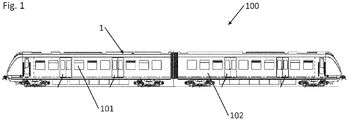
- Fig. 1 shows a rail vehicle 100 with a device 1 for air conditioning an interior 101 of the rail vehicle 100.
- the device 1 may be at least partially disposed in an area of the vehicle roof.
- the operation of the device 1 for air conditioning of the interior 101 of the rail vehicle 100 will be clarified.
- the interior 101 is arranged to receive persons.
- the device 1 for air conditioning is provided substantially within the car body 102.
- the device for air conditioning may be arranged at least partially or completely on the roof outside the car body, on an underfloor area below the car body or in the car body.
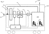
- the device 1 for air conditioning in this case has an air conditioner 15 with a channel 2, which produces an inlet 3, for example outside the car body 102 and an outlet 4 in a downstream channel system for air distribution into the interior 101 and thus a fluidic connection between the environment and the interior 101 ,
- a filter device 5 In the channel 2 or in the air conditioner 15, a filter device 5, a heat exchanger device 6, a fan 7 and a measuring device 8 for measuring a volume or mass flow of a moving air in the channel 2 is arranged.
- the Measuring device 8 can also be installed in the air conditioner 15 downstream air duct system 16. According to the order of enumeration, these individual components are arranged in the flow direction in the channel 2, wherein immediately downstream of the inlet 3, the filter device 5 is provided downstream, followed by the heat exchanger 6, the fan 7 and ultimately of the measuring device.
- a recirculating air channel 9 which fluidly connects the interior 101 with the channel 2, and thus air can be introduced from the interior 101 into a region at the inlet 3 or in the flow direction in front of the filter device 5 in the channel by means of suitable switching elements and ventilation devices , In this way, the air flow in the channel 2 can be completely or partially realized by air from the interior 101.
- the air circulates between the interior 101 and the device 1, whereby the interior 1 has no fluidic connection to the environment. This can be advantageous, for example, to protect the passengers from exposure to polluted air in a tunnel passage.
- the device 1 comprises a control unit 10, wherein the control unit 10 is formed and connected to the heat exchanger device 6 and the fan 7 so that a cooling or heating power of the heat exchanger device 6 and / or a capacity or speed of the fan 7 by the control unit 10 can be adjusted.
- the actual value of the air mass flow, the volume flow or the flow velocity of the air flow in the channel 2 or air duct system 16 is measured and passed on to the control unit 10.
- the measurement of the flow velocity can be carried out via the volume flow or the mass flow or by means of other measuring methods.
- the control unit 10 may be equipped with conversion algorithms or conversion tables to the real value from the measured mass of mass flow at the location of the measuring device 8 Flow rate directly on or just behind the outlet 4 or air speed in space 101 to close.
- the control unit 10 is set so that the air velocity in the interior 101 or flow velocity of the air flow directly at the outlet 4 a does not exceed certain maximum value. If during the use of the device 1, the filter device 5 increasingly polluted, the flow resistance increases by this. This reduces the volume flow in the channel 2, which in turn can be determined by the measuring device 8. According to this reduction, the control unit 10 increases the flow rate or speed of the fan 7 to compensate for the increased flow resistance through the clogged filter device 5. This ensures that in each case sufficient air flow can be introduced into the interior 101 of the rail vehicle 100, which is required for the generation of specifically the cooling capacity.
- thermosensors are provided, and depending on the embodiment, these may also be used individually or in combination. All measurement signals of the temperature sensors are forwarded to the control unit 10 and can thus be used to control the heat exchanger device 6.
- a first temperature sensor 11 is arranged in the channel 2, in particular in the region of the air conditioning unit 15, in order to be able to record the temperature of the air flow in the duct 2 or air conditioner 15.
- the control includes the ability to adjust the temperature of the air flow in the channel 2, and thus also the outflowing air flow, by means of the heat exchanger device 6.
- the first temperature sensor 11 is preferably arranged directly or in the immediate vicinity of the measuring device 8.
- the temperature in the interior 101 is measured by a second temperature sensor 12, so that the real situation in the area of the passengers can be recorded and used for temperature control.
- a third temperature sensor 13 is provided on an outer side of the car body 102 of the rail vehicle 100.
- the temperature in the recirculating air channel 9 are measured by means of a fourth temperature sensor 14 and passed to the control unit 10.
- the knowledge of the temperature in the recirculating air channel 9 causes a temperature of the flowing into the inner space 101 a flowing air flow, for example, by mixing air from the environment and from the interior 101 can be adjusted.
Abstract
Die Erfindung betrifft ein Verfahren zum Betrieb einer Vorrichtung zum Klimatisieren eines Schienenfahrzeugs. Mit der Erfindung wird eine verbesserte Vorrichtung zum Klimatisieren bereitgestellt, wobei insbesondere eine verlässliche Bereitstellung eines klimatisierenden Luftstroms sichergestellt werden soll. Dazu wird ein Verfahren angeführt, wobei die Vorrichtung ein Gerät zum Durchströmen von Luft aufweist. In dem Gerät ist eine Filtervorrichtung (5) vorgesehen, wobei diese unmittelbar am Einlass des Kanals (2) angeordnet sein kann. Der Filtervorrichtung nachgeschaltet folgt eine Wärmetauschervorrichtung (6) zum Beeinflussen einer Temperatur der im Kanal vorhandenen Luft. Mithilfe eines Lüfters (7) wird Luft vom Einlass zum Auslass durch den Kanal bewegt. Der Luftstrom wird in Richtung des Auslasses durch den Kanal gefördert, wobei eine Messvorrichtung (8) zur Messung zur Bestimmung des Masse- oder Volumenstroms stromaufwärts zum Auslass im Kanal angeordnet ist. Zuerst wird ein SOLL-Masse- oder Volumenstrom im des Geräts vorgegeben. In einem weiteren Schritt wird der IST-Masse- oder Volumenstrom des Luftstroms durch den Kanal des Geräts gemessen und mit dem SOLL-Wert verglichen. Entsprechend der Differenz zwischen SOLL-Masse- oder Volumenstrom und IST-Masse- oder Volumenstrom wird in einem nächsten Schritt die Drehzahl des Lüfters derart nachgeregelt, dass sich der vorhandene IST-Masse- oder Volumenstrom dem Zielwert und eine Reduzierung durch eine Filterverschmutzung ausgleicht.The invention relates to a method for operating a device for conditioning a rail vehicle. With the invention, an improved device for air conditioning is provided, wherein in particular a reliable provision of an air-conditioning air flow is to be ensured. For this purpose, a method is given, wherein the device comprises a device for the passage of air. In the device, a filter device (5) is provided, which can be arranged directly at the inlet of the channel (2). Downstream of the filter device follows a heat exchanger device (6) for influencing a temperature of the air present in the channel. A fan (7) moves air from the inlet to the outlet through the duct. The air stream is conveyed through the channel in the direction of the outlet, wherein a measuring device (8) for measuring the mass or volume flow is arranged upstream of the outlet in the channel. First, a nominal mass or volume flow in the device is specified. In a further step, the actual mass or volume flow of the air flow through the channel of the device is measured and compared with the target value. In a next step, the speed of the fan is readjusted in accordance with the difference between the nominal mass or volumetric flow and the actual mass or volumetric flow such that the existing actual mass or volumetric flow compensates for the target value and a reduction due to filter contamination.
Description
Die vorliegende Erfindung betrifft ein Verfahren zum Betrieb einer Vorrichtung zum Klimatisieren eines Innenraums eines Fahrzeugs. Ein solches Fahrzeug, zum Beispiel ausgebildet als Schienenfahrzeug, kann zum Personentransport dienen. Weiterhin betrifft die Erfindung eine Vorrichtung zum Klimatisieren eines solchen Fahrzeugs, wobei der Komfort von Fahrgästen erhöht wird.The present invention relates to a method of operating a device for air conditioning an interior of a vehicle. Such a vehicle, for example designed as a rail vehicle, can be used for passenger transport. Furthermore, the invention relates to a device for air conditioning such a vehicle, wherein the comfort of passengers is increased.
Klimavorrichtungen für Fahrzeuge sind bereits aus der Kraftfahrzeug-, Schienenfahrzeugtechnik und aus Luftfahrt bekannt. Dabei gilt es, Temperaturen in Innenräumen dieser Fahr- und Flugzeuge beeinflussen zu können.Air conditioning devices for vehicles are already known from the automotive, rail vehicle and aviation. It is important to be able to influence temperatures indoors of these vehicles and aircraft.
In der
Die
Die bisher bekannten Ausführungen einer Klimavorrichtung, einer Klimaanlage oder einer Klimatisierungseinrichtung erfordern bei Messungen von Funktionsparametern eine Interpretation von Messdaten, um eine verlässliche Aussage über den Betriebszustand einer Klimaanlage zu erhalten. Weiterhin birgt diese Interpretation eine gewisse Fehlerquelle, wodurch es zu unzutreffenden Annahmen kommen kann.The hitherto known embodiments of an air conditioning device, an air conditioning system or an air conditioning device require an interpretation of measured data for measurements of functional parameters in order to obtain a reliable statement about the operating state of an air conditioning system. Furthermore, this interpretation has a certain source of error, which may lead to incorrect assumptions.
Aufgabe der vorliegenden Erfindung ist es daher, eine verbesserte Vorrichtung zum Klimatisieren eines Innenraums eines Fahrzeugs bereitzustellen, wobei insbesondere eine verlässliche Bereitstellung eines klimatisierenden Luftstroms sichergestellt werden soll.The object of the present invention is therefore to provide an improved device for air conditioning an interior of a vehicle, wherein in particular a reliable provision of an air-conditioning air flow is to be ensured.
Die obige Aufgabe wird durch ein Verfahren nach Anspruch 1, eine Vorrichtung nach Anspruch 9 und ein Fahrzeug nach Anspruch 15 gelöst. Vorteilhafte Ausführungsformen ergeben sich aus den abhängigen Unteransprüchen.The above object is achieved by a method according to
Das Verfahren dient dabei zum Betrieb einer Vorrichtung zum Klimatisieren eines Innenraums eines Fahrzeugs. Die Vorrichtung weist einen Kanal zum Durchströmen von Luft gemäß einer Strömungsrichtung auf, wobei ein Einlass zum Ansaugen von Luft am Anfang und ein Auslass zum Ausblasen von Luft am Ende des Kanals vorgesehen sind.The method is used to operate a device for air conditioning an interior of a vehicle. The apparatus has a passage for flowing air in a flow direction, with an inlet for sucking air at the beginning and an outlet for blowing air at the end of the passage.
In dem Kanal ist eine Filtervorrichtung zum Herausfiltern von Staub und Partikeln aus der Luft vorgesehen, wobei diese, nicht zwingend, unmittelbar am Einlass des Kanals angeordnet sein kann. Darunter fällt auch eine solche Anordnung, bei der die Filtervorrichtung unmittelbar oder im Bereich vor dem Einlass vorgesehen ist.In the channel, a filter device for filtering out dust and particles from the air is provided, which, not necessarily, can be arranged directly at the inlet of the channel. This also includes such an arrangement in which the filter device is provided directly or in the region in front of the inlet.
Der Filtervorrichtung nachgeschaltet folgt mittel- oder unmittelbar, betrachtet in Strömungsrichtung des Kanals, eine Wärmetauschervorrichtung zum Beeinflussen einer Temperatur der im Kanal vorhandenen Luft bzw. diesen durchströmenden Luft. Dabei kann die Wärmetauschervorrichtung zum Heizen und/oder Kühlen ausgebildet sein.Downstream of the filter device follows, medium or directly, viewed in the direction of flow of the channel, a heat exchanger device for influencing a temperature of the air present in the channel or the air flowing through it. In this case, the heat exchanger device may be designed for heating and / or cooling.
Mithilfe eines Lüfters wird Luft vom Einlass zum Auslass durch den Kanal gefördert. Gemäß einer Ausführungsform ist der Lüfter in Strömungsrichtung der Wärmetauschervorrichtung nachgeschaltet. Folglich saugt der Lüfter Umgebungsluft in den Einlass des Kanals, worauf der Luftstrom die Filtervorrichtung passiert und dadurch gereinigt wird. Darauf folgend durchströmt die Luft die Wärmetauschervorrichtung und erreicht den Lüfter.A fan delivers air from the inlet to the outlet through the duct. According to one embodiment, the fan is connected downstream in the flow direction of the heat exchanger device. Consequently, the fan sucks ambient air into the inlet of the channel, whereupon the air flow passes through the filter device and is thereby cleaned. Following this, the air flows through the heat exchanger device and reaches the fan.
Gemäß einer anderen Ausführungsform ist der Lüfter stromaufwärts der Wärmetauschervorrichtung angeordnet und saugt Luft durch die Filtervorrichtung und fördert bzw. pumpt diese angesaugte Luft weiter durch die Wärmetauschervorrichtung.According to another embodiment, the fan is arranged upstream of the heat exchanger device and sucks air through the filter device and further conveys or sucked this sucked air through the heat exchanger device.
Unabhängig von den voran beschriebenen Ausführungsformen wird die Luft bzw. der Luftstrom in Richtung des Auslasses durch den Kanal gefördert, wobei eine Messvorrichtung zur Bestimmung eines Massestroms oder Volumenstroms des Luftstroms stromaufwärts zum Auslass im Kanal angeordnet ist. Die Messvorrichtung ist also der Wärmetauschervorrichtung, dem Lüfter und der Filtervorrichtung in Strömungsrichtung nachgeschaltet im Kanal vorgesehen. Mithilfe dieser Messvorrichtung kann entweder direkt oder indirekt der Volumenstrom- oder Massestrom, und gemäß einer Ausführung dadurch auch die Strömungsgeschwindigkeit des Luftstroms durch den Kanal, bzw. am Ort der Messung bestimmt werden.Regardless of the embodiments described above, the air or the air flow is conveyed in the direction of the outlet through the channel, wherein a measuring device for determining a mass flow or volume flow of the air flow is arranged upstream of the outlet in the channel. The measuring device is thus the heat exchanger device, the fan and the filter device downstream provided in the channel in the flow direction. With the help of this measuring device, either directly or indirectly, the volumetric flow or mass flow and, according to one embodiment, also the flow velocity of the air flow through the channel or at the location of the measurement can be determined.
Beispielsweise ist die Messvorrichtung im Bereich des Auslasses des Kanals angeordnet, sodass diese den Volumen- oder Massestrom erfasst, welcher gleich der, insbesondere ähnlich, oder im Wesentlichen proportional zur Ausströmgeschwindigkeit des Luftstroms direkt am oder nach dem Auslass ist. Auf diese Weise kann auch ein Rückschluss auf die Luftgeschwindigkeit im Innenraum ist gezogen werden.For example, the measuring device is arranged in the region of the outlet of the channel, so that it detects the volume or mass flow which is equal to, in particular similar to, or substantially proportional to the outflow velocity of the air flow directly at or after the outlet. In this way, a conclusion on the air speed in the interior is drawn.
Das Verfahren umfasst weiterhin die Schritte, dass zuerst ein SOLL-Volumen- oder Massestrom des Luftstroms im Kanal oder am Auslass des Kanals bestimmt oder vorgegeben wird. Dies kann beispielsweise ein zulässiger Maximalwert für den Volumen- oder Massestrom, oder auch - umgerechnet oder ermittelt - die Ausströmgeschwindigkeit des aus dem Auslass austretenden und in den Innenraum eintretenden Luftstroms sein. In einem weiteren Schritt wird der IST-Volumen- oder Massestrom des Luftstroms des Luftstroms durch den Kanal gemessen und mit dem SOLL-Wert des Volumen- oder Massestroms des Luftstroms verglichen. Der Ort der IST-Messung korreliert oder stimmt mit dem Ort über ein, an dem der SOLL-Volumen- oder Massestrom erwünscht ist. Wenn beispielsweise der SOLL-Volumen- oder Massestrom eine tatsächliche Strömungsgeschwindigkeit des ausströmenden Luftstroms am Auslass oder Luftgeschwindigkeit im Raum repräsentiert, und die Bestimmung bzw. Messung des IST-Volumen- oder Massestroms des Luftstroms an einem anderen Ort im Kanal stattfindet, so ist eine geeignete Korrelation zwischen dem Volumen- oder Massestrom oder der Strömungsgeschwindigkeit am Auslass oder im Innenraum und dem Volumen- oder Massestrom oder der Strömungsgeschwindigkeit an der Messvorrichtung zu identifizieren und zu berücksichtigen. Grundsätzlich besteht die Möglichkeit, über die Dichte der Luft, den Massenstrom in einen Volumenstrom oder umgekehrt umzurechnen und diesen für die weiteren Betrachtungen zu nutzen. Die Umrechnung kann dabei in Abhängigkeit von der Temperatur des Luftstromes erfolgen.The method further includes the steps of first determining or specifying a desired volumetric or mass flow of the airflow in the duct or at the outlet of the duct. This may be, for example, a permissible maximum value for the volumetric or mass flow, or also - converted or determined - the outflow velocity of the air flow emerging from the outlet and entering the interior. In a further step, the actual volume or mass flow of the air flow of the air flow is measured through the channel and compared with the target value of the volume flow or mass flow of the air flow. The location of the ACTUAL measurement correlates or coincides with the location where the DES target volumetric or mass flow is desired. For example, if the SOLL volumetric or mass flow represents an actual flow velocity of the effluent airflow at the outlet or air velocity in space, and the determination of the actual volumetric or mass flow of the airflow is at a different location in the duct, then a suitable one To identify and consider the correlation between the volume or mass flow or the flow rate at the outlet or in the interior and the volume or mass flow or the flow velocity at the measuring device. Basically, there is the possibility of converting the density of the air, the mass flow into a flow or vice versa and this for the further considerations. The conversion can be done depending on the temperature of the air flow.
Entsprechend der Differenz zwischen SOLL-Volumen- oder Massestrom oder SOLL-Strömungsgeschwindigkeit und der IST-Volumen- oder Massestrom oder der IST-Strömungsgeschwindigkeit wird in einem nächsten Schritt die Förderleistung oder auch die Drehzahl des Lüfters derart eingestellt, dass sich der vorhandene IST-Volumen- oder Massestrom oder die IST-Strömungsgeschwindigkeit dem Zielwert des SOLL-Volumen- oder Massestroms oder der SOLL-Strömungsgeschwindigkeit des Luftstroms angleicht.According to the difference between the target volumetric flow or mass flow or nominal flow velocity and the actual volumetric or mass flow or the actual flow velocity, in a next step the delivery rate or the rotational speed of the fan is set in such a way that the existing actual volume - or mass flow or the actual flow rate equal to the target value of the target volume or mass flow or the target flow rate of the air flow.
Gemäß einer Ausführungsform kann der SOLL-Volumen- oder Massestrom oder die SOLL-Strömungsgeschwindigkeit des Luftstroms durch den Kanal derart gewählt werden, dass eine gewünschte Luftgeschwindigkeit im Innenraum oder Ausströmgeschwindigkeit des Luftstroms an oder direkt nach dem Auslass bestimmten Parametern entspricht, insbesondere einen Maximalwert nicht überschreitet. Es können dazu wiederum Umrechnungsalgorithmen oder Umrechnungstabellen verwendet werden, insbesondere um von der IST-Volumen- oder Massestrom oder der IST-Strömungsgeschwindigkeit am Ort der Messung bzw. der Messvorrichtung im Kanal auf den realen, ausströmenden Volumen- oder Massestrom oder die reale Ausströmgeschwindigkeit an oder in unmittelbarer Umgebung nach dem Auslass zu schließen.According to one embodiment, the desired volume or mass flow or the desired flow rate of the air flow through the duct can be selected such that a desired air speed in the interior or outflow speed of the air flow at or directly after the outlet corresponds to certain parameters, in particular does not exceed a maximum value , In turn, conversion algorithms or conversion tables can be used for this purpose, in particular of the actual volume or mass flow or the actual flow velocity at the location of the measurement or the measuring device in the channel to the real, outflowing volume or mass flow or the real outflow velocity or close to the outlet in the immediate vicinity.
Denkbar ist beispielsweise, dass eine Luftgeschwindigkeit im Innenraum bzw. eine Ausströmgeschwindigkeit des Luftstroms beim Einströmen in den Innenraum eines Fahrzeugs einen bestimmten Wert nicht überschreiten darf, um Komfortansprüchen von Personen in diesem Innenraum gerecht zu werden. Ein zu starker Luftstrom, d. h. ein Luftstrom mit einer hohen Strömungsgeschwindigkeit, Volumen- oder Massenstrom, kann von Personen in dem Innenraum unangenehm als Zugluft empfunden werden und ist deshalb unerwünscht.It is conceivable, for example, that an airspeed in the interior or an outflow velocity of the airflow when flowing into the interior of a vehicle must not exceed a certain value in order to meet the comfort requirements of persons in this interior. Too much airflow, d. H. an air flow with a high flow velocity, volume or mass flow, can be unpleasantly perceived by people in the interior as draft and is therefore undesirable.
Gemäß einer weiteren Ausführungsform des Verfahrens wird mithilfe der Messvorrichtung eine Verringerung des Luftstroms, bedingt durch Verschmutzung der Filtervorrichtung und/oder einer Komponente, z.B. der Wärmetauschervorrichtung und deren im Luftstrom angeordneter Verdampfer, durch die Messvorrichtung detektiert und mithilfe der Regeleinheit über den Lüfter kompensiert. Auf diese Weise wird erstmalig erreicht, dass die Dimensionierung von Wärmetauschern für solche Vorrichtungen zum Klimatisieren geringer ausfallen kann. Anstelle einer Überdimensionierung der Wärmetauscher, um z.B. die Kälteleistung auch bei einem verringerten Volumenstrom bzw. Massenstrom zur Verfügung zu stellen, kann nun der reduzierte Volumenstrom bzw. Massenstrom angehoben und die erforderliche Kälteleistung wieder bereitgestellt werden. Auf diese Weise wird verhindert, dass unnötige Leistungsreserven der Wärmetauschervorrichtung vorgehalten werden müssen, um z.B. eine erforderliche Kälteleistung zu erzielen.According to a further embodiment of the method, a reduction of the air flow due to contamination of the filter device and / or a component, eg the heat exchanger device and its evaporator arranged in the air flow, detected by the measuring device and compensated by means of the control unit via the fan using the measuring device. In this way it is achieved for the first time that the dimensioning of heat exchangers for such devices for air conditioning can be lower. Instead of oversizing the Heat exchangers, for example, to provide the cooling capacity at a reduced flow rate or mass flow available, now the reduced flow rate or mass flow can be increased and the required cooling capacity can be provided again. In this way prevents unnecessary power reserves of the heat exchanger device must be kept in order to achieve, for example, a required cooling capacity.
Gemäß einer Ausführung wird der Wert des Volumen- oder Massestroms oder der Strömungsgeschwindigkeit des ausströmenden Luftstroms aus dem Auslass und damit auch des sich im Innenraum befindlichen Luftstroms bei der erfindungsgemäßen Vorrichtung auf einen Maximalwert begrenzt, sodass der Komfort der Passagiere nicht beeinträchtigt wird. Dies erfolgt durch die oben beschriebene Regelung bzw. Regeleinheit in Zusammenwirken mit der Messvorrichtung im Kanal. Wird infolge des Betriebs der Vorrichtung zum Klimatisieren deren Filtervorrichtung zunehmend zugesetzt, so kann die damit verbundene Reduzierung der Ausströmgeschwindigkeit bzw. des Volumen- oder Massenstroms durch die Vorrichtung durch Erhöhung der Lüfterleistung kontinuierlich kompensiert werden. Damit kann die Luftgeschwindigkeit im Raum unabhängig von einem Zustand der Filtervorrichtung konstant und innerhalb der Komfortparameter gehalten werden.According to one embodiment, the value of the volume or mass flow or the flow velocity of the outflowing air flow from the outlet and thus also the air flow located in the interior is limited to a maximum value in the inventive device, so that the comfort of the passengers is not impaired. This is done by the control or regulating unit described above in cooperation with the measuring device in the channel. If, as a result of the operation of the device for air conditioning, its filter device is increasingly added, the associated reduction of the outflow velocity or of the volume or mass flow through the device can be continuously compensated by increasing the fan power. Thus, the air velocity in space can be kept constant and within the comfort parameters regardless of a state of the filter device.
Gemäß eines Aspekts der Erfindung weist die Messvorrichtung einen Massenstromsensor zur Messung des Massenstroms des Luftstroms im Kanal auf. Die Messvorrichtung zur Messung eines Luftmassenstroms kann beispielsweise ein Luftmassenstromsensor sein, der im Englischen als "mass air flow meter" oder kurz MAF bezeichnet wird. Die Verwendung eines Luftmassenstromsensors bietet den Vorteil, dass der Luftmassenstrom direkt erfasst wird und daher die Masse der durch den Kanal strömenden Luft von der Regeleinheit als Regelgröße verwendet wird.According to one aspect of the invention, the measuring device has a mass flow sensor for measuring the mass flow of the air flow in the channel. The measuring device for measuring an air mass flow may, for example, be an air mass flow sensor, which is referred to in English as "mass air flow meter" or MAF for short. The use of an air mass flow sensor has the advantage that the air mass flow is detected directly and therefore the mass of the air flowing through the channel is used by the control unit as a controlled variable.
Auf Basis einer Messung des Massenstroms wird im Folgenden der IST-Volumenstrom, und insbesondere auf diesem Wege auch die Strömungsgeschwindigkeit des Luftstroms bestimmt. Hierzu erfolgt eine Umrechnung über die Dichte. Diese kann infolge der Erfassung der Temperatur am Auslass temperaturabhängig erfolgen.On the basis of a measurement of the mass flow, the actual volumetric flow, and in particular in this way, the flow velocity of the air flow is determined in the following. This is done by converting over the density. This can be temperature-dependent as a result of the detection of the temperature at the outlet.
Die Verwendung eines Massenstromsensors birgt den Vorteil, dass die Konzeption der Messvorrichtung im Kanal äußerst einfach ist, da Massenstromsensoren robust, zuverlässig und kostengünstig sind.The use of a mass flow sensor has the advantage that the design of the measuring device in the channel is extremely simple, since mass flow sensors are robust, reliable and cost-effective.
Gemäß einer besonderen Ausprägung der Erfindung wird der Luftdruck des Luftstroms, insbesondere vorab festgelegt und/oder nicht gemessen und bewertet. Da die Dichte der durch den Kanal strömenden Luft vorrangig von der Temperatur abhängig ist, kann bevorzugt ein erster Temperatursensor im Kanal, bevorzugt in Strömungsrichtung nach dem Lüfter, vorgesehen sein.According to a particular embodiment of the invention, the air pressure of the air flow, in particular determined in advance and / or not measured and evaluated. Since the density of the air flowing through the channel is primarily dependent on the temperature, preferably a first temperature sensor in the channel, preferably in the flow direction downstream of the fan, may be provided.
In diesem Zusammenhang kann direkt aus dem gemessenen Massenstrom und der Temperatur auf den Volumenstrom des Luftstroms oder auf die Strömungsgeschwindigkeit geschlossen werden. Insbesondere kann dazu ein vorab angenommenes Verhältnis zwischen Temperatur und Dichte des Luftstroms verwendet werden. Dies bewirkt, dass die Vorrichtung zur Klimatisierung eines Fahrzeugs besonders einfach und günstig dargestellt werden kann. Entgegen der bestehenden Expertenerwartung wird gemäß dieser Ausführungsform gerade nicht der Luftdruck aufgenommen. Schwankungen des zu regelnden Volumenstroms oder der Strömungsgeschwindigkeit, welche durch variierenden Luftdruck bedingt sind, werden dabei bewusst in Kauf genommen, um die vorteilhafte Ausbildung der Vorrichtung zu erreichen.In this connection it can be concluded directly from the measured mass flow and the temperature on the volume flow of the air flow or on the flow velocity. In particular, a pre-assumed relationship between temperature and density of the air flow can be used. This causes the device for air conditioning of a vehicle can be displayed very easily and cheaply. Contrary to the existing expert expectation, in accordance with this embodiment, the air pressure is not being recorded. Fluctuations in the volume flow to be controlled or the flow velocity, which are caused by varying air pressure, are deliberately accepted in order to achieve the advantageous design of the device.
Der Luftmassensensor kann beispielsweise nach dem Prinzip eines Hitzdrahtanemometers arbeiten. Hitzdrahtanemometer sind sehr zuverlässig, benötigen nur einen geringen Bauraum und verfügen nicht über sich bewegenden Teile. Die Messvorrichtung zur Messung eines Luftmassenstroms kann daher auch über zwei oder mehrere Luftmassensensoren verfügen.The air mass sensor can, for example, operate on the principle of a hot wire anemometer. Hot wire anemometers are very reliable, require only a small space and do not have moving parts. The measuring device for measuring an air mass flow can therefore also have two or more air mass sensors.
Die Verwendung von Luftmassensensoren bietet weiterhin den Vorteil, dass eine Erfassung nur an einer Stelle, beispielsweise nah am Auslass, erfolgen muss und z.B. hierfür keine Querschnittsänderungen erforderlich sind, wie bei Differenzdruck-Messern. Regelungen auf Basis von Druckunterschieden benötigen hierzu Sensoren in unterschiedlichen Bereichen des Kanals, die auch unterschiedliche Temperaturen aufweisen können.The use of air mass sensors further offers the advantage that detection must take place only at one point, for example close to the outlet, and e.g. no cross-sectional changes are required, as with differential pressure knives. Controls based on pressure differences require sensors in different areas of the channel, which can also have different temperatures.
Alternativ zur oben genannten Ausführungsform kann die Messvorrichtung als Durchflusssensor zu Bestimmung eines Volumenstroms ausgeführt werden. Dadurch wird die Bestimmung der Strömungsgeschwindigkeit besonders einfach, weil Druck und Temperatur des Luftstroms im Kanal zur Bestimmung der Strömungsgeschwindigkeit in diesem Fall nicht notwendiger Weise bekannt sein müssen. Denkbar dafür sind unmittelbare Volumenzähler oder mittelbare Volumenzähler.Alternatively to the above-mentioned embodiment, the measuring device can be designed as a flow sensor for determining a volume flow. As a result, the determination of the flow velocity becomes particularly simple, because pressure and temperature of the air flow in the channel for determining the flow velocity in this case need not necessarily be known. Conceivable for this are direct volumetric or indirect volumetric meters.
Gemäß einer Ausführung kann die Temperatur des Luftstroms im Kanal mittels des ersten Temperatursensors gemessen werden, wobei das Messergebnis von der Regeleinheit dazu verwendet wird, die Wärmetauschervorrichtung hinsichtlich des Bedarfs an Wärme- bzw. Kälteleistung optimal anzusteuern und den Angleich der IST-Temperatur an die SOLL-Temperatur, insbesondere im Raum, schneller vorzunehmen. Weiterhin kann diese Temperatur als Korrekturfaktor für die Dichte des Luftvolumenstromes dienen.According to one embodiment, the temperature of the air flow in the channel can be measured by means of the first temperature sensor, wherein the measurement result is used by the control unit to optimally control the heat exchanger device with respect to the need for heat and cooling capacity and the adjustment of the actual temperature to the target -Temperature, especially in the room to make faster. Furthermore, this temperature can serve as a correction factor for the density of the air volume flow.
Gemäß einer weiteren Ausführungsform des Verfahrens wird in einem ersten Schritt die SOLL-Temperatur für den Innenraum bestimmt oder eingestellt. In einem zweiten Schritt wird die IST-Temperatur in dem Innenraum des Fahrzeugs mittels eines zweiten, im Innenraum angeordneten Temperatursensors gemessen und mit der SOLL-Temperatur verglichen. Auf Basis einer festgestellten Differenz der Temperaturen wird der Wärme- oder Kälteleistungsbedarf bestimmt und die Wärmetauschervorrichtungen über die Regeleinheit angesteuert, sodass sich die IST-Temperatur der SOLL-Temperatur des Innenraumes angleicht.According to a further embodiment of the method, the set temperature for the interior is determined or set in a first step. In a second step, the actual temperature in the interior of the vehicle is measured by means of a second, arranged in the interior temperature sensor and compared with the target temperature. Based on a detected difference in the temperatures, the heat or cooling capacity requirement is determined and the heat exchanger devices are controlled via the control unit, so that the actual temperature is equal to the set temperature of the interior.
Die Regelung der Temperatur kann weiterhin verbessert werden, indem gemäß einer weiteren Ausführungsform die Außentemperatur mittels eines dritten Temperatursensors gemessen wird und zur Steuerung des Wärmetauschers durch die Regeleinheit verwendet wird.The regulation of the temperature can be further improved by measuring the outside temperature by means of a third temperature sensor according to a further embodiment and is used to control the heat exchanger by the control unit.
Zudem ist es möglich, zumindest teilweise Luft aus dem Innenraum über einen Umluftkanal in einen Anfangsbereich, insbesondere Lufteintrittsbereich des Kanals zuzuführen, wobei insbesondere eine Temperatur des Luftstroms im Umluftkanal mittels eines vierten Temperatursensors gemessen werden kann.In addition, it is possible, at least partially, to supply air from the interior via a recirculating air channel into an initial region, in particular the air inlet region of the channel, wherein in particular a temperature of the air stream in the recirculating air channel can be measured by means of a fourth temperature sensor.
Im Rahmen der Erfindung wird eine Vorrichtung zum Klimatisieren eines Innenraums eines Fahrzeugs, insbesondere eines Schienenfahrzeugs offenbart, welche einen Kanal zum Führen und/oder Konditionieren eines Luftstroms in einer Strömungsrichtung mit einem Einlass und einem Auslass zur Abgabe des Luftstroms, insbesondere über ein Kanalsystem in den Innenraum des Fahrzeugs aufweist. Der Kanal wiederum umfasst eine Filtervorrichtung, eine Wärmetauschervorrichtung, einen Lüfter und eine Messvorrichtung zur Bestimmung des Luftmasse- oder Volumenstroms, oder der Strömungsgeschwindigkeit eines Luftstroms im Kanal. Dabei ist die Messvorrichtung der Wärmetauschervorrichtung dem Lüfter und der Filtervorrichtung in Strömungsrichtung nachgeschaltet im Kanal oder dem nachfolgenden Zuluftkanal vorgesehen. Dies führt zu einer Verbesserung der Regelung der Vorrichtung, da die für die Regelung relevanten Daten, wie Luftmassen- oder Volumenstrom, oder Strömungsgeschwindigkeit, in Strömungsrichtung nach den Komponenten aufgenommen bzw. gemessen werden, welche den Luftstrom beeinflussen würden.In the context of the invention, a device for air conditioning an interior of a vehicle, in particular a rail vehicle is disclosed, which has a channel for guiding and / or conditioning an air flow in a flow direction with an inlet and an outlet for discharging the air flow, in particular via a duct system in the Interior of the vehicle has. The channel in turn comprises a filter device, a heat exchanger device, a fan and a measuring device for determining the air mass or volume flow, or the flow velocity of an air flow in the channel. In this case, the measuring device of the heat exchanger device is provided downstream of the fan and the filter device in the flow direction in the channel or the subsequent supply air duct. This leads to an improvement of the scheme the device, since the data relevant to the control, such as air mass or volume flow, or flow rate, are recorded or measured in the flow direction for the components that would affect the air flow.
Gemäß einer Ausführung umfasst die Vorrichtung zum Klimatisieren ein Klimagerät, wobei der Kanal im Klimagerät angeordnet ist. Dem Klimagerät nachgeschaltet ist ein Zuluftkanalsystem zur Verteilung der Luft auf die Auslässe im Innenraum des Schienenfahrzeugs vorgesehen. Weiterhin kann dem Klimagerät vorgeschaltet ein primär Luftkanalsystem angeordnet sein, welches den Einlass des Klimageräts mit einem Einlass an einer Außenseite des Schienenfahrzeugs verbindet. In diesem Zusammenhang kann gemäß einer speziellen Ausführungsform die Messvorrichtung in dem nachgeschalteten Zuluftkanal System installiert sein.According to one embodiment, the device for air conditioning comprises an air conditioner, wherein the channel is arranged in the air conditioner. Downstream of the air conditioner, a supply air duct system for distributing the air to the outlets in the interior of the rail vehicle is provided. Furthermore, the air conditioner upstream of a primary air duct system may be arranged, which connects the inlet of the air conditioner with an inlet on an outer side of the rail vehicle. In this connection, according to a special embodiment, the measuring device can be installed in the downstream supply air duct system.
Die Vorrichtung umfasst weiterhin eine Regeleinheit zum Einstellen der Drehzahl oder der Förderleistung des Lüfters, die mit der Messvorrichtung zu Bestimmung des Luftvolumen- oder Massenstroms, und damit auch - unter Berücksichtigung des jeweiligen Querschnitts des Kanals - der Strömungsgeschwindigkeit verbunden und dazu eingerichtet ist, das oben genannte Verfahren oder Ausführungsformen davon auszuführen. Dafür muss die Regeleinheit mit entsprechender Vorabinformation und Regelkreisen ausgestattet sein, um die vorteilhafte Regelung wie oben beschrieben umsetzen zu können. Insbesondere ist in diesem Zusammenhang anzuführen, dass die Regeleinheit mit Informationen zu Verhältnissen von Massenstrom, Volumenstrom, Strömungsgeschwindigkeit und Querschnitten des Kanals ausgestattet sein muss, insbesondere unter Berücksichtigung von Temperatur und/oder unter Nichtberücksichtigung des Drucks.The device further comprises a control unit for adjusting the speed or the delivery rate of the fan, which is connected to the measuring device for determining the air volume or mass flow, and thus - taking into account the respective cross section of the channel - the flow rate and is adapted to the above to perform said method or embodiments thereof. For this, the control unit must be equipped with appropriate preliminary information and control loops in order to implement the advantageous control as described above. In particular, it should be mentioned in this context that the control unit must be equipped with information on ratios of mass flow, volume flow, flow velocity and cross sections of the channel, in particular taking into account temperature and / or disregarding the pressure.
Gemäß einer Ausführungsform ist die Regeleinheit dabei derart ausgebildet oder weist entsprechende Umrechnungsalgorithmen oder Umrechnungstabellen (Look-Up-Table) auf, sodass aus den Messergebnissen der Messvorrichtung ein IST-Volumenstrom oder eines IST-Strömungsgeschwindigkeit des Luftstroms am Ort der Messvorrichtung im Kanal bestimmt werden kann. Zudem ist die Regeleinheit so gestaltet und eingerichtet, dass mittels des bestimmten IST-Volumenstromes ein SOLL-Volumenstrom, oder mittels der bestimmten IST-Strömungsgeschwindigkeit eine SOLL-Strömungsgeschwindigkeit der Luft durch den Kanal einstellbar ist.According to one embodiment, the control unit is embodied in this way or has corresponding conversion algorithms or conversion tables (look-up table) so that an actual volume flow or an actual flow speed of the air flow at the location of the measuring device in the channel can be determined from the measurement results of the measuring device , In addition, the control unit is designed and set up so that by means of the determined actual volume flow a desired volume flow, or by means of the determined actual flow speed, a desired flow rate of the air through the channel is adjustable.
Gemäß einer Ausführungsform weist die Vorrichtung einen ersten Temperatursensor auf, welcher dem Lüfter nachgeschaltet und insbesondere der Messvorrichtung vorgeschaltet im Kanal angeordnet ist. Um die Messsignale des ersten Temperatursensors an die Regeleinheit zu übertragen, ist dieser mit der Regeleinheit verbunden. Weiterhin ist die Regeleinheit mit der Wärmetauschervorrichtung verbunden und dazu ausgebildet den Betrieb dieser zu steuern, sodass eine Temperatur des Luftstroms im Kanal oder des aus dem Auslass ausströmenden Luftstroms einstellbar ist. Somit ist es möglich, in gleichzeitiger Weise und unabhängig vom Zustand der Filtervorrichtung sowohl Ausströmgeschwindigkeit und Temperatur des aus dem Auslass ausströmenden Luftstroms einzustellen. Dies führt zu einem erhöhten Komfort der Passagiere im Innenraum des Fahrzeugs.According to one embodiment, the device has a first temperature sensor, which is connected downstream of the fan and, in particular, is arranged upstream of the measuring device in the channel. In order to transmit the measurement signals of the first temperature sensor to the control unit, this is connected to the control unit. Furthermore, the control unit is connected to the heat exchanger device and designed to control the operation of this, so that a temperature of the air flow in the channel or the air flow flowing out of the outlet is adjustable. Thus, it is possible to adjust both outflow velocity and temperature of the airflow flowing out of the outlet in a simultaneous manner and independently of the condition of the filter device. This leads to increased comfort of the passengers in the interior of the vehicle.
Eine weitere Ausführungsform offenbart, dass in dem Innenraum des Fahrzeugs ein zweiter Temperatursensor angebracht ist, welcher durch Übertragungsmittel zum Übertragen von Messsignalen mit der Regeleinheit verbunden ist. Dies führt zu einer weiteren Verbesserung der Regelung der Vorrichtung, da der Temperaturzustand im Innenraum des Fahrzeugs zur Regelung des Luftstroms verwendet werden kann.Another embodiment discloses that in the interior of the vehicle, a second temperature sensor is attached, which is connected by transmission means for transmitting measurement signals to the control unit. This leads to a further improvement of the control of the device, since the temperature state in the interior of the vehicle can be used to control the air flow.
Weiterhin ist gemäß einer Ausführungsform vorgesehen, einen dritten Temperatursensor außen am Fahrzeug anzuordnen, welcher mittels Übertragungsmittel mit der Regeleinheit verbunden ist. Die Information über die außen am Fahrzeug vorliegende Temperatur führt zu einer weiteren Verbesserung der Regelung der Vorrichtung, und wird insbesondere zum Einstellen der Leistung der Wärmetauschervorrichtung verwendet.Furthermore, it is provided according to an embodiment, to arrange a third temperature sensor on the outside of the vehicle, which is connected by means of transmission means with the control unit. The information on the outside of the vehicle temperature leads to a further improvement of the control of the device, and is used in particular for adjusting the performance of the heat exchanger device.
In Erweiterung dieses Grundprinzips wird erfindungsgemäß vorgeschlagen, einen Umluftkanal zum Zuführen von Luft aus dem Innenraum hin zur Vorrichtung, insbesondere in Strömungsrichtung in einen Bereich des Kanals vor der Filtervorrichtung, vorzusehen. Auf diese Weise kann der aus dem Auslass ausströmende und in den Innenraum einströmende Luftstrom vollständig oder teilweise durch Luft aus dem Innenraum gebildet werden. Somit kann der Energieaufwand beim Kühlen oder Heizen des Luftstroms reduziert werden, wenn das Temperaturniveau der rückgeführten Luft bereits der gewünschten Temperatur entspricht.In extension of this basic principle, the invention proposes to provide a recirculating air duct for supplying air from the interior to the device, in particular in the flow direction in a region of the channel in front of the filter device. In this way, the airflow flowing out of the outlet and flowing into the interior air flow can be completely or partially formed by air from the interior. Thus, the energy consumption when cooling or heating the air flow can be reduced when the temperature level of the recirculated air already corresponds to the desired temperature.
Weiterhin wird offenbart, einen vierten Temperatursensor im Umluftkanal vorzusehen, welcher mit der Regeleinheit zum Übertragen von Messsignalen verbunden ist. Auf diese Weise ist eine Lufttemperatur im Umluftkanal messbar, wodurch die Temperaturregelung abermals präzisiert wird.Furthermore, it is disclosed to provide a fourth temperature sensor in the circulating air channel, which is connected to the control unit for transmitting measurement signals. In this way, an air temperature in the circulating air channel can be measured, whereby the temperature control is specified again.
Gemäß einer Ausführungsform ist die Wärmetauschervorrichtung als kombinierte Heiz-und/oder Kühlvorrichtung, vorzugsweise als eine einzige Baueinheit, ausgebildet, wodurch ermöglicht wird, den Luftstrom zu kühlen als auch zu erwärmen und ein besonders breites Temperaturspektrum zu ermöglichen. Denkbar ist auch, dass solche Funktionen von einer Mehrzahl von unterschiedlichen Wärmetauschervorrichtungen ausgeführt werden, wobei ein Verdampfer zum Kühlen des Luftstroms und/oder eine Heizvorrichtung zum Erwärmen des Luftstroms im Kanal vorgesehen ist. Vorzugsweise sind die Heizvorrichtung und die Kühlvorrichtung direkt beieinander im Kanal angeordnet.According to one embodiment, the heat exchanger device is designed as a combined heating and / or cooling device, preferably as a single unit, which makes it possible to cool the air flow as well as to heat and to allow a particularly wide temperature spectrum. It is also conceivable that such functions are performed by a plurality of different heat exchanger devices, wherein an evaporator for cooling the air flow and / or a heater for heating the air flow is provided in the channel. Preferably, the heating device and the cooling device are arranged directly next to each other in the channel.
Gemäß eines Aspekts der Erfindung wird offenbart, das beschriebene Ausführungsformen des Verfahrens und beschriebenen Ausführungsformen der Vorrichtung zu verwenden, um negative Auswirkungen einer Verschmutzung der Filtervorrichtung und/oder der Wärmetauschervorrichtung zu kompensieren und diesen entgegenzuwirken. Insbesondere die Verwendung des Verfahrens und der Vorrichtung im Zusammenhang mit Personentransportfahrzeug bewirkt eine Steigerung des Komforts der betroffenen Passagiere. Im Rahmen der Erfindung wurde erkannt, dass eine Verschmutzung von Komponenten der Vorrichtung zum Klimatisieren kontinuierlich erfolgt, jedoch währenddessen ständig Passagiere betroffen sind. Eine Verringerung des Zuluftvolumenstroms kann dabei zu einer Nichteinhaltung der geforderten klimatischen Bedingungen führen. Ein zu großer Zuluftvolumenstrom wird hingegen im Innenraum als Zugluft wahrgenommen und ist zu vermeiden. Diese Erkenntnis ermöglichte, die beschriebenen Ausführungsformen des erfindungsgemäßen Verfahrens erstmalig vorteilhaft einzusetzen.According to one aspect of the invention, it is disclosed to use the described embodiments of the method and described embodiments of the device to compensate for and counteract negative effects of contamination of the filter device and / or the heat exchanger device. In particular, the use of the method and the device in connection with passenger transport vehicle causes an increase in the comfort of the passengers concerned. In the context of the invention it has been recognized that contamination of components of the device for air conditioning takes place continuously, but during which passengers are constantly affected. A reduction in the supply air volume flow can lead to non-compliance with the required climatic conditions. On the other hand, too large a supply air volume flow is perceived as drafts in the interior and must be avoided. This finding made it possible for the first time to advantageously use the described embodiments of the method according to the invention.
Gemäß einer weiteren Ausführung wird ein Fahrzeug, insbesondere ein Schienenfahrzeug, offenbart, umfassend eine Vorrichtung zum Klimatisieren gemäß einer oder mehreren der oben beschriebenen Ausführungen.According to a further embodiment, a vehicle, in particular a rail vehicle, is disclosed, comprising a device for air conditioning according to one or more of the embodiments described above.
Die vorstehend beschriebenen Ausführungsformen können beliebig miteinander kombiniert werden.The above-described embodiments may be arbitrarily combined with each other.
Die beiliegenden Zeichnungen veranschaulichen Ausführungsformen und dienen zusammen mit der Beschreibung der Erläuterung der Prinzipien der Erfindung. Die Elemente der Zeichnungen sind relativ zueinander und nicht notwendigerweise maßstabsgetreu. Gleiche Bezugszeichen bezeichnen entsprechend ähnliche Teile.
-
Fig. 1 zeigt ein Schienenfahrzeug mit einer Vorrichtung zum Klimatisieren, und -
Fig. 2 ist eine schematische Darstellung der Vorrichtung gemäßFig. 1 .
-
Fig. 1 shows a rail vehicle with a device for air conditioning, and -
Fig. 2 is a schematic representation of the device according toFig. 1 ,
Anhand der schematischen
Gemäß einer hier nicht dargestellten Ausführungsform kann die Vorrichtung zum Klimatisieren zumindest teilweise oder vollständig auf dem Dach außerhalb des Wagenkastens, an einem Unterflurbereich unterhalb des Wagenkastens oder auch im Wagenkasten angeordnet sein.According to an embodiment not shown here, the device for air conditioning may be arranged at least partially or completely on the roof outside the car body, on an underfloor area below the car body or in the car body.
Die Vorrichtung 1 zum Klimatisieren weist dabei ein Klimagerät 15 mit einem Kanal 2 auf, welcher einen Einlass 3 beispielsweise außerhalb des Wagenkastens 102 und einen Auslass 4 in ein nachgelagertes Kanalsystem zur Luftverteilung in den Innenraum 101 und somit eine strömungstechnische Verbindung zwischen Umgebung und Innenraum 101 herstellt.The
Im Kanal 2 bzw. im Klimagerät 15 ist eine Filtervorrichtung 5, eine Wärmetauschervorrichtung 6, einen Lüfter 7 und eine Messvorrichtung 8 zum Messen eines Volumen- oder Massenstroms eines sich im Kanal 2 bewegenden Luftstroms angeordnet. Die Messvorrichtung 8 kann dabei auch im dem Klimagerät 15 nachgelagerten Luftkanalsystem 16 installiert sein. Entsprechend der Aufzählungsreihenfolge sind diese einzelnen Komponenten in Strömungsrichtung im Kanal 2 angeordnet, wobei unmittelbar oder mittelbar nach dem Einlass 3 die Filtervorrichtung 5 nachgeschaltet vorgesehen ist, gefolgt von dem Wärmetauscher 6, dem Lüfter 7 und letztendlich von der Messvorrichtung 8.In the
Weiterhin ist ein Umluftkanal 9 vorgesehen, welcher den Innenraum 101 mit dem Kanal 2 strömungstechnisch verbindet, und somit mittels geeigneter Schaltelemente und gegebenenfalls Lüftungsvorrichtungen Luft aus dem Innenraum 101 in einen Bereich am Einlass 3 oder in Strömungsrichtung vor der Filtervorrichtung 5 in den Kanal eingebracht werden kann. Auf diese Weise kann der Luftstrom im Kanal 2 vollständig oder teilweise durch Luft aus dem Innenraum 101 realisiert werden. Bei vollständiger Versorgung über den Umluftkanal 9 zirkuliert die Luft zwischen Innenraum 101 und Vorrichtung 1, wodurch der Innenraum 1 keine strömungstechnische Verbindung zur Umgebung aufweist. Dies kann vorteilhaft sein, um zum Beispiel bei einer Tunneldurchfahrt die Fahrgäste vor einer Belastung durch verschmutzte Luft zu schützen.Furthermore, a
Weiterhin umfasst die Vorrichtung 1 eine Regeleinheit 10, wobei die Regeleinheit 10 dazu ausgebildet und mit der Wärmetauschervorrichtung 6 und dem Lüfter 7 so verbunden ist, dass eine Kühl- oder Heizleistung der Wärmetauschervorrichtung 6 und/oder eine Förderleistung oder Drehzahl des Lüfters 7 durch die Regeleinheit 10 eingestellt werden können.Furthermore, the
Mithilfe der Messvorrichtung 8 wird der IST-Wert des Luftmassenstroms, des Volumenstroms bzw. der Strömungsgeschwindigkeit des Luftstroms im Kanal 2 oder Luftkanalsystem 16 gemessen und an die Regeleinheit 10 weitergegeben. Die Messung der Strömungsgeschwindigkeit kann über den Volumenstrom oder den Massestrom oder mittels anderer Messverfahren durchgeführt werden. Für den Fall wird, dass - wie im vorliegenden Ausführungsbeispiel - die Messvorrichtung 8 nicht unmittelbar am Auslass 4 angeordnet ist, kann die Regeleinheit 10 mit Umrechnungsalgorithmen oder Umrechnungstabellen ausgestattet sein, um vom Messwert des Volumen- der Massestroms am Ort der Messvorrichtung 8 auf die reale Strömungsgeschwindigkeit direkt am oder kurz hinter dem Auslass 4 oder Luftgeschwindigkeit im Raum 101 schließen zu können.By means of the measuring
Grundsätzlich ist die Regeleinheit 10 so eingestellt, dass die Luftgeschwindigkeit im Innenraum 101 oder Strömungsgeschwindigkeit des Luftstroms direkt am Auslass 4 einen gewissen maximalen Wert nicht überschreitet. Wird während des Einsatzes der Vorrichtung 1 die Filtervorrichtung 5 zunehmend verschmutzt, erhöht sich der Strömungswiderstand durch diese. Dadurch reduziert sich der Volumenstrom im Kanal 2, was wiederum durch die Messvorrichtung 8 festgestellt werden kann. Entsprechend dieser Reduktion erhöht die Regeleinheit 10 die Förderleistung bzw. Drehzahl des Lüfters 7, um den erhöhten Strömungswiderstand durch die verstopfte Filtervorrichtung 5 auszugleichen. Somit wird sichergestellt, dass in jedem Fall ein ausreichender Luftstrom in den Innenraum 101 des Schienenfahrzeugs 100 eingeleitet werden kann, der für die Erzeugung speziell der Kälteleistung erforderlich ist.Basically, the
Weiterhin ist eine Reihe von Temperatursensoren vorgesehen, wobei je nach Ausführungsform diese auch einzeln oder in Kombination zum Einsatz kommen können. Sämtliche Messsignale der Temperatursensoren werden an die Regeleinheit 10 weitergegeben und können somit zur Ansteuerung der Wärmetauschervorrichtung 6 verwendet werden.Furthermore, a number of temperature sensors are provided, and depending on the embodiment, these may also be used individually or in combination. All measurement signals of the temperature sensors are forwarded to the
Ein erster Temperatursensor 11 ist im Kanal 2, insbesondere im Bereich des Klimageräts 15 angeordnet, um die Temperatur des Luftstroms im Kanal 2 bzw. Klimagerät 15 aufnehmen zu können. Auf diese Weise umfasst die Regelung die Fähigkeit die Temperatur des Luftstroms in dem Kanal 2, und damit auch die des ausströmenden Luftstroms, mittels der Wärmetauschervorrichtung 6 einstellen zu können.A
Der erste Temperatursensor 11 ist vorzugsweise direkt oder in unmittelbarer Umgebung der Messvorrichtung 8 angeordnet.The
In verbesserter Art und Weise wird durch einen zweiten Temperatursensor 12 die Temperatur im Innenraum 101 gemessen, sodass die reale Situation im Bereich der Fahrgäste aufgenommen und zur Temperaturregelung verwendet werden kann.In an improved manner, the temperature in the
Mit dem Wissen um die Temperatur an einer Außenseite des Schienenfahrzeugs 100 bzw. der Außentemperatur wird ermöglicht, die Effektivität der Ansteuerung und insbesondere die Leistungsaufnahme der Wärmetauschervorrichtung 6 zu optimieren. Zur Messung der Außentemperatur ist an einer Außenseite des Wagenkastens 102 des Schienenfahrzeugs 100 ein dritter Temperatursensor 13 vorgesehen.Knowing the temperature at an outside of the
Im Fall dass eine Rückführung von Luft aus dem Innenraum 101 in den Kanal 2 vorgenommen wird, kann gemäß eines Ausführungsbeispiels die Temperatur im Umluftkanal 9 mithilfe eines vierten Temperatursensors 14 gemessen werden und an die Regeleinheit 10 weitergegeben werden. Die Kenntnis über die Temperatur im Umluftkanal 9 bewirkt, dass eine Temperatur des in den Innenraum 101 ein strömenden Luftstroms beispielsweise auch durch Mischen von Luft aus der Umgebung und aus dem Innenraum 101 eingestellt werden kann.In the event that a return of air from the
Wenngleich hierin spezifische Ausführungsformen dargestellt und beschrieben worden sind, liegt es im Rahmen der vorliegenden Erfindung, die gezeigten Ausführungsformen geeignet zu modifizieren, ohne vom Schutzbereich der vorliegenden Erfindung abzuweichen. Die nachfolgenden Ansprüche stellen einen ersten, nicht bindenden Versuch dar, die Erfindung allgemein zu definieren.While specific embodiments have been illustrated and described herein, it is within the scope of the present invention to properly modify the illustrated embodiments without departing from the scope of the present invention. The following claims are a first, non-binding attempt to broadly define the invention.
- 11
- Vorrichtung zum KlimatisierenDevice for air conditioning
- 22
- Kanalchannel
- 33
- Einlassinlet
- 44
- Auslassoutlet
- 55
- Filtervorrichtungfilter means
- 66
- Wärmetauschervorrichtungheat exchanger device
- 77
- LüfterFan
- 88th
- Messvorrichtungmeasurement device
- 99
- Umluftkanalreturn air duct
- 1010
- Regeleinheitcontrol unit
- 1111
- erster Temperatursensorfirst temperature sensor
- 1212
- zweiter Temperatursensorsecond temperature sensor
- 1313
- dritter Temperatursensorthird temperature sensor
- 1414
- vierter Temperatursensorfourth temperature sensor
- 1515
- Klimagerätair conditioning
- 1616
- Zuluftkanalsupply air duct
- 100100
- Schienenfahrzeugtrack vehicle
- 101101
- Innenrauminner space
- 102102
- Wagenkastencar body
Claims (15)
der Kanal (2) einen Einlass (3) und einen Auslass (4) zur Abgabe des Luftstroms in den Innenraum (101), eine Filtervorrichtung (5), eine Wärmetauschervorrichtung (6), einen Lüfter (7) und eine Messvorrichtung (8) zur Bestimmung eines Massestroms oder Volumenstroms aufweist, und die Messvorrichtung (8) der Wärmetauschervorrichtung (6), dem Lüfter (7) und der Filtervorrichtung (5) in Strömungsrichtung nachgeschaltet im Kanal (2) angeordnet ist, und
wobei das Verfahren die Schritte aufweist:
the channel (2) has an inlet (3) and an outlet (4) for discharging the air flow into the interior space (101), a filter device (5), a heat exchanger device (6), a fan (7) and a measuring device (8) for determining a mass flow or volume flow, and the measuring device (8) of the heat exchanger device (6), the fan (7) and the filter device (5) in the flow direction downstream in the channel (2) is arranged, and
the method comprising the steps of:
Applications Claiming Priority (1)
| Application Number | Priority Date | Filing Date | Title |
|---|---|---|---|
| DE102015117665.3A DE102015117665A1 (en) | 2015-10-16 | 2015-10-16 | DEVICE FOR AIR-CONDITIONING AN INTERIOR OF A VEHICLE, IN PARTICULAR A RAIL VEHICLE |
Publications (2)
| Publication Number | Publication Date |
|---|---|
| EP3156302A1 true EP3156302A1 (en) | 2017-04-19 |
| EP3156302B1 EP3156302B1 (en) | 2020-07-08 |
Family
ID=57178260
Family Applications (1)
| Application Number | Title | Priority Date | Filing Date |
|---|---|---|---|
| EP16193712.3A Active EP3156302B1 (en) | 2015-10-16 | 2016-10-13 | Device for conditioning an interior of a railway vehicle |
Country Status (2)
| Country | Link |
|---|---|
| EP (1) | EP3156302B1 (en) |
| DE (1) | DE102015117665A1 (en) |
Cited By (2)
| Publication number | Priority date | Publication date | Assignee | Title |
|---|---|---|---|---|
| CN108413548A (en) * | 2018-05-11 | 2018-08-17 | 苏州大学 | A kind of subway carriage placement ventilation device and control method |
| CN110949428A (en) * | 2019-12-09 | 2020-04-03 | 交控科技股份有限公司 | Train air conditioner parameter adjusting method and system |
Families Citing this family (3)
| Publication number | Priority date | Publication date | Assignee | Title |
|---|---|---|---|---|
| DE102017223338B3 (en) | 2017-12-20 | 2019-04-25 | Siemens Aktiengesellschaft | Vehicle with temperature control for the passenger compartment |
| DE102020001527A1 (en) * | 2020-03-10 | 2021-09-16 | Gentherm Gmbh | Method for operating a temperature control fan |
| DE102021102517B4 (en) * | 2021-02-03 | 2022-12-08 | Carl Freudenberg Kg | Method and device for operating a ventilation system for air in an interior |
Citations (9)
| Publication number | Priority date | Publication date | Assignee | Title |
|---|---|---|---|---|
| JPS5682624A (en) * | 1979-12-07 | 1981-07-06 | Nippon Denso Co Ltd | Controlling device for blower of air-conditioning device for automobile |
| US4518032A (en) * | 1981-11-11 | 1985-05-21 | Hitachi, Ltd. | Temperature control apparatus for automobile air-conditioning systems |
| EP0326044A2 (en) * | 1988-01-23 | 1989-08-02 | MAN GHH Schienenverkehrstechnik GmbH | Device for smoothing out air pressure shocks in the passenger accommodation of railway vehicles |
| EP0570288A1 (en) * | 1992-05-14 | 1993-11-18 | Valeo Thermique Habitacle | Ventilation device for a vehicle compartment |
| DE19847504C1 (en) * | 1998-10-15 | 2000-11-16 | Deutsche Bahn Ag | Fresh and recycled air volume control method for air-conditioning unit for automobile passenger space regulates ratio of fresh and recycled air volumes in dependence on detected air quality and required air temperature |
| US20060130497A1 (en) | 2004-12-20 | 2006-06-22 | Carrier Corporation | Method and control for testing air filter condition in HVAC system |
| WO2010145954A1 (en) | 2009-06-15 | 2010-12-23 | Bombardier Transportation Gmbh | Railway vehicle comprising an air conditioning system |
| DE102010032636A1 (en) * | 2010-07-29 | 2012-02-02 | Daimler Ag | Aerator i.e. air conditioning apparatus, for e.g. passenger car, has heat exchanger for pressurizing air with thermal energy, and sensor for detecting mass flow of air and/or thermal energy brought with air into passenger compartment |
| WO2012103641A1 (en) * | 2011-02-04 | 2012-08-09 | Bombardier Transportation Gmbh | A ventilation system for a passenger transit vehicle |
Family Cites Families (2)
| Publication number | Priority date | Publication date | Assignee | Title |
|---|---|---|---|---|
| DE10036502C1 (en) * | 2000-07-27 | 2002-04-18 | Behr Hella Thermocontrol Gmbh | Air conditioning system for vehicle compares sensor signal with reference signal for reference operating state to determine whether degree of filter fouling exceeds defined value |
| DE10316294B4 (en) * | 2003-04-09 | 2006-06-14 | Siemens Ag | Method for controlling an air conditioning system for a motor vehicle |
-
2015
- 2015-10-16 DE DE102015117665.3A patent/DE102015117665A1/en not_active Ceased
-
2016
- 2016-10-13 EP EP16193712.3A patent/EP3156302B1/en active Active
Patent Citations (9)
| Publication number | Priority date | Publication date | Assignee | Title |
|---|---|---|---|---|
| JPS5682624A (en) * | 1979-12-07 | 1981-07-06 | Nippon Denso Co Ltd | Controlling device for blower of air-conditioning device for automobile |
| US4518032A (en) * | 1981-11-11 | 1985-05-21 | Hitachi, Ltd. | Temperature control apparatus for automobile air-conditioning systems |
| EP0326044A2 (en) * | 1988-01-23 | 1989-08-02 | MAN GHH Schienenverkehrstechnik GmbH | Device for smoothing out air pressure shocks in the passenger accommodation of railway vehicles |
| EP0570288A1 (en) * | 1992-05-14 | 1993-11-18 | Valeo Thermique Habitacle | Ventilation device for a vehicle compartment |
| DE19847504C1 (en) * | 1998-10-15 | 2000-11-16 | Deutsche Bahn Ag | Fresh and recycled air volume control method for air-conditioning unit for automobile passenger space regulates ratio of fresh and recycled air volumes in dependence on detected air quality and required air temperature |
| US20060130497A1 (en) | 2004-12-20 | 2006-06-22 | Carrier Corporation | Method and control for testing air filter condition in HVAC system |
| WO2010145954A1 (en) | 2009-06-15 | 2010-12-23 | Bombardier Transportation Gmbh | Railway vehicle comprising an air conditioning system |
| DE102010032636A1 (en) * | 2010-07-29 | 2012-02-02 | Daimler Ag | Aerator i.e. air conditioning apparatus, for e.g. passenger car, has heat exchanger for pressurizing air with thermal energy, and sensor for detecting mass flow of air and/or thermal energy brought with air into passenger compartment |
| WO2012103641A1 (en) * | 2011-02-04 | 2012-08-09 | Bombardier Transportation Gmbh | A ventilation system for a passenger transit vehicle |
Cited By (2)
| Publication number | Priority date | Publication date | Assignee | Title |
|---|---|---|---|---|
| CN108413548A (en) * | 2018-05-11 | 2018-08-17 | 苏州大学 | A kind of subway carriage placement ventilation device and control method |
| CN110949428A (en) * | 2019-12-09 | 2020-04-03 | 交控科技股份有限公司 | Train air conditioner parameter adjusting method and system |
Also Published As
| Publication number | Publication date |
|---|---|
| DE102015117665A1 (en) | 2017-04-20 |
| EP3156302B1 (en) | 2020-07-08 |
Similar Documents
| Publication | Publication Date | Title |
|---|---|---|
| EP3156302B1 (en) | Device for conditioning an interior of a railway vehicle | |
| DE4031113C2 (en) | ||
| EP2870414B1 (en) | Method for operating a heat exchanger and hvac installation for implementing the method | |
| DE19947567A1 (en) | Device for air conditioning in motor vehicles | |
| WO2017101896A2 (en) | Neck fan for a vehicle seat and control method therefor | |
| DE19711031B4 (en) | Heating, ventilation and / or air conditioning with power control, in particular for motor vehicles | |
| DE19615239C1 (en) | Heating and/or air-conditioning system operating method for motor vehicle | |
| DE102014002419A1 (en) | Vehicle air conditioning | |
| DE10036502C1 (en) | Air conditioning system for vehicle compares sensor signal with reference signal for reference operating state to determine whether degree of filter fouling exceeds defined value | |
| DE102017202872B4 (en) | Method and device for determining the discharge temperatures of an automatic air conditioning system of a vehicle | |
| DE102009023671A1 (en) | Device for cooling battery and part of inner chamber in vehicle, comprises air conditioner with air channel, where air flow is blown into air channel | |
| WO2011038883A1 (en) | Method and apparatus for air-conditioning for at least one vehicle interior and a battery unit | |
| DE102017104646A1 (en) | Air conditioning device for a motor vehicle | |
| DE10208851B4 (en) | Automotive air conditioning system for the interior of a transport vehicle | |
| EP1187733B1 (en) | Device for controlling the interior temperature of a motor vehicle | |
| DE10112969A1 (en) | Air conditioning system for motor vehicle has cooler unit installed outside vehicle's interior, and air ducts have several decentrally disposed flow functioning units with heat exchanger and air temperature control element | |
| DE102008024766A1 (en) | Method for identifying requirements of interchange of air filter of motor vehicle ventilation unit or air conditioning unit, involves determining total quantity of air, which is flown through air filter from predetermined time point | |
| DE102014210264A1 (en) | Air conditioning and air temperature control | |
| DE19711033A1 (en) | Heating, ventilation and air-conditioning system for motor vehicle | |
| EP1364820B1 (en) | Apparatus and Method for heating and/or cooling the interior of a vehicle | |
| EP3480529A1 (en) | Method for air conditioning of rooms of a building | |
| DE19719287A1 (en) | Air conditioning system for the interior of a vehicle | |
| DE10036509C1 (en) | Air outlet for air flowing into vehicle interior has sensors for measuring speed of sub-flows of air near outlet opening mounted in channel interior behind deflection elements near outlet | |
| EP3299195B1 (en) | Method to control an air conditioning device for a vehicle | |
| DE102006012400B4 (en) | Heating and ventilation system for a vehicle with a cold air bypass downstream of the mixing flap |
Legal Events
| Date | Code | Title | Description |
|---|---|---|---|
| PUAI | Public reference made under article 153(3) epc to a published international application that has entered the european phase |
Free format text: ORIGINAL CODE: 0009012 |
|
| STAA | Information on the status of an ep patent application or granted ep patent |
Free format text: STATUS: THE APPLICATION HAS BEEN PUBLISHED |
|
| AK | Designated contracting states |
Kind code of ref document: A1 Designated state(s): AL AT BE BG CH CY CZ DE DK EE ES FI FR GB GR HR HU IE IS IT LI LT LU LV MC MK MT NL NO PL PT RO RS SE SI SK SM TR |
|
| AX | Request for extension of the european patent |
Extension state: BA ME |
|
| RAP1 | Party data changed (applicant data changed or rights of an application transferred) |
Owner name: BOMBARDIER TRANSPORTATION GMBH |
|
| STAA | Information on the status of an ep patent application or granted ep patent |
Free format text: STATUS: REQUEST FOR EXAMINATION WAS MADE |
|
| 17P | Request for examination filed |
Effective date: 20171013 |
|
| RBV | Designated contracting states (corrected) |
Designated state(s): AL AT BE BG CH CY CZ DE DK EE ES FI FR GB GR HR HU IE IS IT LI LT LU LV MC MK MT NL NO PL PT RO RS SE SI SK SM TR |
|
| GRAP | Despatch of communication of intention to grant a patent |
Free format text: ORIGINAL CODE: EPIDOSNIGR1 |
|
| STAA | Information on the status of an ep patent application or granted ep patent |
Free format text: STATUS: GRANT OF PATENT IS INTENDED |
|
| INTG | Intention to grant announced |
Effective date: 20200127 |
|
| GRAS | Grant fee paid |
Free format text: ORIGINAL CODE: EPIDOSNIGR3 |
|
| GRAA | (expected) grant |
Free format text: ORIGINAL CODE: 0009210 |
|
| STAA | Information on the status of an ep patent application or granted ep patent |
Free format text: STATUS: THE PATENT HAS BEEN GRANTED |
|
| AK | Designated contracting states |
Kind code of ref document: B1 Designated state(s): AL AT BE BG CH CY CZ DE DK EE ES FI FR GB GR HR HU IE IS IT LI LT LU LV MC MK MT NL NO PL PT RO RS SE SI SK SM TR |
|
| REG | Reference to a national code |
Ref country code: CH Ref legal event code: EP Ref country code: AT Ref legal event code: REF Ref document number: 1288140 Country of ref document: AT Kind code of ref document: T Effective date: 20200715 |
|
| REG | Reference to a national code |
Ref country code: DE Ref legal event code: R096 Ref document number: 502016010427 Country of ref document: DE |
|
| REG | Reference to a national code |
Ref country code: IE Ref legal event code: FG4D Free format text: LANGUAGE OF EP DOCUMENT: GERMAN |
|
| REG | Reference to a national code |
Ref country code: CH Ref legal event code: NV Representative=s name: DENNEMEYER AG, CH |
|
| REG | Reference to a national code |
Ref country code: LT Ref legal event code: MG4D |
|
| REG | Reference to a national code |
Ref country code: NL Ref legal event code: MP Effective date: 20200708 |
|
| PG25 | Lapsed in a contracting state [announced via postgrant information from national office to epo] |
Ref country code: FI Free format text: LAPSE BECAUSE OF FAILURE TO SUBMIT A TRANSLATION OF THE DESCRIPTION OR TO PAY THE FEE WITHIN THE PRESCRIBED TIME-LIMIT Effective date: 20200708 Ref country code: PT Free format text: LAPSE BECAUSE OF FAILURE TO SUBMIT A TRANSLATION OF THE DESCRIPTION OR TO PAY THE FEE WITHIN THE PRESCRIBED TIME-LIMIT Effective date: 20201109 Ref country code: LT Free format text: LAPSE BECAUSE OF FAILURE TO SUBMIT A TRANSLATION OF THE DESCRIPTION OR TO PAY THE FEE WITHIN THE PRESCRIBED TIME-LIMIT Effective date: 20200708 Ref country code: BG Free format text: LAPSE BECAUSE OF FAILURE TO SUBMIT A TRANSLATION OF THE DESCRIPTION OR TO PAY THE FEE WITHIN THE PRESCRIBED TIME-LIMIT Effective date: 20201008 Ref country code: ES Free format text: LAPSE BECAUSE OF FAILURE TO SUBMIT A TRANSLATION OF THE DESCRIPTION OR TO PAY THE FEE WITHIN THE PRESCRIBED TIME-LIMIT Effective date: 20200708 Ref country code: GR Free format text: LAPSE BECAUSE OF FAILURE TO SUBMIT A TRANSLATION OF THE DESCRIPTION OR TO PAY THE FEE WITHIN THE PRESCRIBED TIME-LIMIT Effective date: 20201009 Ref country code: NO Free format text: LAPSE BECAUSE OF FAILURE TO SUBMIT A TRANSLATION OF THE DESCRIPTION OR TO PAY THE FEE WITHIN THE PRESCRIBED TIME-LIMIT Effective date: 20201008 Ref country code: HR Free format text: LAPSE BECAUSE OF FAILURE TO SUBMIT A TRANSLATION OF THE DESCRIPTION OR TO PAY THE FEE WITHIN THE PRESCRIBED TIME-LIMIT Effective date: 20200708 Ref country code: SE Free format text: LAPSE BECAUSE OF FAILURE TO SUBMIT A TRANSLATION OF THE DESCRIPTION OR TO PAY THE FEE WITHIN THE PRESCRIBED TIME-LIMIT Effective date: 20200708 |
|
| PG25 | Lapsed in a contracting state [announced via postgrant information from national office to epo] |
Ref country code: PL Free format text: LAPSE BECAUSE OF FAILURE TO SUBMIT A TRANSLATION OF THE DESCRIPTION OR TO PAY THE FEE WITHIN THE PRESCRIBED TIME-LIMIT Effective date: 20200708 Ref country code: LV Free format text: LAPSE BECAUSE OF FAILURE TO SUBMIT A TRANSLATION OF THE DESCRIPTION OR TO PAY THE FEE WITHIN THE PRESCRIBED TIME-LIMIT Effective date: 20200708 Ref country code: RS Free format text: LAPSE BECAUSE OF FAILURE TO SUBMIT A TRANSLATION OF THE DESCRIPTION OR TO PAY THE FEE WITHIN THE PRESCRIBED TIME-LIMIT Effective date: 20200708 Ref country code: IS Free format text: LAPSE BECAUSE OF FAILURE TO SUBMIT A TRANSLATION OF THE DESCRIPTION OR TO PAY THE FEE WITHIN THE PRESCRIBED TIME-LIMIT Effective date: 20201108 |
|
| PG25 | Lapsed in a contracting state [announced via postgrant information from national office to epo] |
Ref country code: NL Free format text: LAPSE BECAUSE OF FAILURE TO SUBMIT A TRANSLATION OF THE DESCRIPTION OR TO PAY THE FEE WITHIN THE PRESCRIBED TIME-LIMIT Effective date: 20200708 |
|
| REG | Reference to a national code |
Ref country code: DE Ref legal event code: R097 Ref document number: 502016010427 Country of ref document: DE |
|
| PG25 | Lapsed in a contracting state [announced via postgrant information from national office to epo] |
Ref country code: RO Free format text: LAPSE BECAUSE OF FAILURE TO SUBMIT A TRANSLATION OF THE DESCRIPTION OR TO PAY THE FEE WITHIN THE PRESCRIBED TIME-LIMIT Effective date: 20200708 Ref country code: SM Free format text: LAPSE BECAUSE OF FAILURE TO SUBMIT A TRANSLATION OF THE DESCRIPTION OR TO PAY THE FEE WITHIN THE PRESCRIBED TIME-LIMIT Effective date: 20200708 Ref country code: CZ Free format text: LAPSE BECAUSE OF FAILURE TO SUBMIT A TRANSLATION OF THE DESCRIPTION OR TO PAY THE FEE WITHIN THE PRESCRIBED TIME-LIMIT Effective date: 20200708 Ref country code: DK Free format text: LAPSE BECAUSE OF FAILURE TO SUBMIT A TRANSLATION OF THE DESCRIPTION OR TO PAY THE FEE WITHIN THE PRESCRIBED TIME-LIMIT Effective date: 20200708 Ref country code: IT Free format text: LAPSE BECAUSE OF FAILURE TO SUBMIT A TRANSLATION OF THE DESCRIPTION OR TO PAY THE FEE WITHIN THE PRESCRIBED TIME-LIMIT Effective date: 20200708 Ref country code: EE Free format text: LAPSE BECAUSE OF FAILURE TO SUBMIT A TRANSLATION OF THE DESCRIPTION OR TO PAY THE FEE WITHIN THE PRESCRIBED TIME-LIMIT Effective date: 20200708 |
|
| PLBE | No opposition filed within time limit |
Free format text: ORIGINAL CODE: 0009261 |
|
| STAA | Information on the status of an ep patent application or granted ep patent |
Free format text: STATUS: NO OPPOSITION FILED WITHIN TIME LIMIT |
|
| PG25 | Lapsed in a contracting state [announced via postgrant information from national office to epo] |
Ref country code: AL Free format text: LAPSE BECAUSE OF FAILURE TO SUBMIT A TRANSLATION OF THE DESCRIPTION OR TO PAY THE FEE WITHIN THE PRESCRIBED TIME-LIMIT Effective date: 20200708 |
|
| 26N | No opposition filed |
Effective date: 20210409 |
|
| GBPC | Gb: european patent ceased through non-payment of renewal fee |
Effective date: 20201013 |
|
| PG25 | Lapsed in a contracting state [announced via postgrant information from national office to epo] |
Ref country code: MC Free format text: LAPSE BECAUSE OF FAILURE TO SUBMIT A TRANSLATION OF THE DESCRIPTION OR TO PAY THE FEE WITHIN THE PRESCRIBED TIME-LIMIT Effective date: 20200708 Ref country code: LU Free format text: LAPSE BECAUSE OF NON-PAYMENT OF DUE FEES Effective date: 20201013 Ref country code: SK Free format text: LAPSE BECAUSE OF FAILURE TO SUBMIT A TRANSLATION OF THE DESCRIPTION OR TO PAY THE FEE WITHIN THE PRESCRIBED TIME-LIMIT Effective date: 20200708 |
|
| REG | Reference to a national code |
Ref country code: BE Ref legal event code: MM Effective date: 20201031 |
|
| PG25 | Lapsed in a contracting state [announced via postgrant information from national office to epo] |
Ref country code: BE Free format text: LAPSE BECAUSE OF NON-PAYMENT OF DUE FEES Effective date: 20201031 Ref country code: SI Free format text: LAPSE BECAUSE OF FAILURE TO SUBMIT A TRANSLATION OF THE DESCRIPTION OR TO PAY THE FEE WITHIN THE PRESCRIBED TIME-LIMIT Effective date: 20200708 Ref country code: GB Free format text: LAPSE BECAUSE OF NON-PAYMENT OF DUE FEES Effective date: 20201013 |
|
| PG25 | Lapsed in a contracting state [announced via postgrant information from national office to epo] |
Ref country code: IE Free format text: LAPSE BECAUSE OF NON-PAYMENT OF DUE FEES Effective date: 20201013 |
|
| PG25 | Lapsed in a contracting state [announced via postgrant information from national office to epo] |
Ref country code: TR Free format text: LAPSE BECAUSE OF FAILURE TO SUBMIT A TRANSLATION OF THE DESCRIPTION OR TO PAY THE FEE WITHIN THE PRESCRIBED TIME-LIMIT Effective date: 20200708 Ref country code: MT Free format text: LAPSE BECAUSE OF FAILURE TO SUBMIT A TRANSLATION OF THE DESCRIPTION OR TO PAY THE FEE WITHIN THE PRESCRIBED TIME-LIMIT Effective date: 20200708 Ref country code: CY Free format text: LAPSE BECAUSE OF FAILURE TO SUBMIT A TRANSLATION OF THE DESCRIPTION OR TO PAY THE FEE WITHIN THE PRESCRIBED TIME-LIMIT Effective date: 20200708 |
|
| PG25 | Lapsed in a contracting state [announced via postgrant information from national office to epo] |
Ref country code: MK Free format text: LAPSE BECAUSE OF FAILURE TO SUBMIT A TRANSLATION OF THE DESCRIPTION OR TO PAY THE FEE WITHIN THE PRESCRIBED TIME-LIMIT Effective date: 20200708 |
|
| P01 | Opt-out of the competence of the unified patent court (upc) registered |
Effective date: 20230822 |
|
| PGFP | Annual fee paid to national office [announced via postgrant information from national office to epo] |
Ref country code: FR Payment date: 20231026 Year of fee payment: 8 Ref country code: DE Payment date: 20231020 Year of fee payment: 8 Ref country code: CH Payment date: 20231102 Year of fee payment: 8 Ref country code: AT Payment date: 20231020 Year of fee payment: 8 |