EP3157018A1 - Electrically conductive materials formed by electrophoresis or dielectrophoresis - Google Patents
Electrically conductive materials formed by electrophoresis or dielectrophoresis Download PDFInfo
- Publication number
- EP3157018A1 EP3157018A1 EP16188209.7A EP16188209A EP3157018A1 EP 3157018 A1 EP3157018 A1 EP 3157018A1 EP 16188209 A EP16188209 A EP 16188209A EP 3157018 A1 EP3157018 A1 EP 3157018A1
- Authority
- EP
- European Patent Office
- Prior art keywords
- electrically conductive
- composite
- conductive
- particles
- dielectric material
- Prior art date
- Legal status (The legal status is an assumption and is not a legal conclusion. Google has not performed a legal analysis and makes no representation as to the accuracy of the status listed.)
- Granted
Links
- 238000001962 electrophoresis Methods 0.000 title claims abstract description 21
- 239000004020 conductor Substances 0.000 title abstract description 39
- 238000004720 dielectrophoresis Methods 0.000 title 1
- 239000002131 composite material Substances 0.000 claims abstract description 75
- 239000003989 dielectric material Substances 0.000 claims abstract description 41
- 230000005684 electric field Effects 0.000 claims abstract description 35
- 239000002245 particle Substances 0.000 claims description 105
- 239000000463 material Substances 0.000 claims description 47
- OKTJSMMVPCPJKN-UHFFFAOYSA-N Carbon Chemical compound [C] OKTJSMMVPCPJKN-UHFFFAOYSA-N 0.000 claims description 31
- 239000004820 Pressure-sensitive adhesive Substances 0.000 claims description 24
- 229910052799 carbon Inorganic materials 0.000 claims description 18
- 229910002804 graphite Inorganic materials 0.000 claims description 6
- 239000010439 graphite Substances 0.000 claims description 6
- 229910021607 Silver chloride Inorganic materials 0.000 claims description 5
- 239000008187 granular material Substances 0.000 claims description 5
- 239000002071 nanotube Substances 0.000 claims description 5
- 150000003839 salts Chemical class 0.000 claims description 5
- 229910052709 silver Inorganic materials 0.000 claims description 5
- 239000004332 silver Substances 0.000 claims description 5
- HKZLPVFGJNLROG-UHFFFAOYSA-M silver monochloride Chemical compound [Cl-].[Ag+] HKZLPVFGJNLROG-UHFFFAOYSA-M 0.000 claims description 5
- 239000003795 chemical substances by application Substances 0.000 claims 1
- 238000000034 method Methods 0.000 abstract description 20
- 239000000853 adhesive Substances 0.000 description 25
- 230000001070 adhesive effect Effects 0.000 description 25
- 238000012360 testing method Methods 0.000 description 15
- 239000010410 layer Substances 0.000 description 12
- 239000002609 medium Substances 0.000 description 11
- 239000000203 mixture Substances 0.000 description 10
- 238000005054 agglomeration Methods 0.000 description 9
- 230000002776 aggregation Effects 0.000 description 9
- 239000000017 hydrogel Substances 0.000 description 9
- XLYOFNOQVPJJNP-UHFFFAOYSA-N water Substances O XLYOFNOQVPJJNP-UHFFFAOYSA-N 0.000 description 9
- 239000003522 acrylic cement Substances 0.000 description 8
- 239000007787 solid Substances 0.000 description 8
- 239000000758 substrate Substances 0.000 description 6
- 230000000694 effects Effects 0.000 description 5
- 229920002799 BoPET Polymers 0.000 description 4
- WCUXLLCKKVVCTQ-UHFFFAOYSA-M Potassium chloride Chemical compound [Cl-].[K+] WCUXLLCKKVVCTQ-UHFFFAOYSA-M 0.000 description 4
- 238000000576 coating method Methods 0.000 description 4
- 238000000151 deposition Methods 0.000 description 4
- 230000008021 deposition Effects 0.000 description 4
- 239000006185 dispersion Substances 0.000 description 4
- -1 e.g. Substances 0.000 description 4
- 239000007788 liquid Substances 0.000 description 4
- 230000008569 process Effects 0.000 description 4
- RYGMFSIKBFXOCR-UHFFFAOYSA-N Copper Chemical compound [Cu] RYGMFSIKBFXOCR-UHFFFAOYSA-N 0.000 description 3
- KFZMGEQAYNKOFK-UHFFFAOYSA-N Isopropanol Chemical compound CC(C)O KFZMGEQAYNKOFK-UHFFFAOYSA-N 0.000 description 3
- LRHPLDYGYMQRHN-UHFFFAOYSA-N N-Butanol Chemical compound CCCCO LRHPLDYGYMQRHN-UHFFFAOYSA-N 0.000 description 3
- 230000008901 benefit Effects 0.000 description 3
- 239000011230 binding agent Substances 0.000 description 3
- 239000006229 carbon black Substances 0.000 description 3
- 239000002041 carbon nanotube Substances 0.000 description 3
- 229910052802 copper Inorganic materials 0.000 description 3
- 239000010949 copper Substances 0.000 description 3
- 230000007423 decrease Effects 0.000 description 3
- 150000002500 ions Chemical class 0.000 description 3
- NIXOWILDQLNWCW-UHFFFAOYSA-N acrylic acid group Chemical group C(C=C)(=O)O NIXOWILDQLNWCW-UHFFFAOYSA-N 0.000 description 2
- 229910021393 carbon nanotube Inorganic materials 0.000 description 2
- 239000011248 coating agent Substances 0.000 description 2
- 238000009826 distribution Methods 0.000 description 2
- 229920001971 elastomer Polymers 0.000 description 2
- 239000000806 elastomer Substances 0.000 description 2
- 230000005611 electricity Effects 0.000 description 2
- 230000008020 evaporation Effects 0.000 description 2
- 238000001704 evaporation Methods 0.000 description 2
- 238000011065 in-situ storage Methods 0.000 description 2
- 239000007791 liquid phase Substances 0.000 description 2
- 230000037361 pathway Effects 0.000 description 2
- 229920000642 polymer Polymers 0.000 description 2
- 239000001103 potassium chloride Substances 0.000 description 2
- 235000011164 potassium chloride Nutrition 0.000 description 2
- 238000009736 wetting Methods 0.000 description 2
- DGAQECJNVWCQMB-PUAWFVPOSA-M Ilexoside XXIX Chemical compound C[C@@H]1CC[C@@]2(CC[C@@]3(C(=CC[C@H]4[C@]3(CC[C@@H]5[C@@]4(CC[C@@H](C5(C)C)OS(=O)(=O)[O-])C)C)[C@@H]2[C@]1(C)O)C)C(=O)O[C@H]6[C@@H]([C@H]([C@@H]([C@H](O6)CO)O)O)O.[Na+] DGAQECJNVWCQMB-PUAWFVPOSA-M 0.000 description 1
- 239000002202 Polyethylene glycol Substances 0.000 description 1
- BQCADISMDOOEFD-UHFFFAOYSA-N Silver Chemical compound [Ag] BQCADISMDOOEFD-UHFFFAOYSA-N 0.000 description 1
- 239000012790 adhesive layer Substances 0.000 description 1
- 230000002411 adverse Effects 0.000 description 1
- 238000013019 agitation Methods 0.000 description 1
- 239000012736 aqueous medium Substances 0.000 description 1
- 230000015572 biosynthetic process Effects 0.000 description 1
- 125000000484 butyl group Chemical group [H]C([*])([H])C([H])([H])C([H])([H])C([H])([H])[H] 0.000 description 1
- 239000003054 catalyst Substances 0.000 description 1
- 230000008859 change Effects 0.000 description 1
- 238000001311 chemical methods and process Methods 0.000 description 1
- 230000001010 compromised effect Effects 0.000 description 1
- 239000003431 cross linking reagent Substances 0.000 description 1
- 238000013461 design Methods 0.000 description 1
- 230000009429 distress Effects 0.000 description 1
- 238000000469 dry deposition Methods 0.000 description 1
- 238000005868 electrolysis reaction Methods 0.000 description 1
- 238000005516 engineering process Methods 0.000 description 1
- 125000001495 ethyl group Chemical group [H]C([H])([H])C([H])([H])* 0.000 description 1
- 239000000945 filler Substances 0.000 description 1
- 239000000499 gel Substances 0.000 description 1
- 230000001939 inductive effect Effects 0.000 description 1
- 239000003999 initiator Substances 0.000 description 1
- 238000012423 maintenance Methods 0.000 description 1
- 230000007246 mechanism Effects 0.000 description 1
- 239000012528 membrane Substances 0.000 description 1
- 230000005012 migration Effects 0.000 description 1
- 238000013508 migration Methods 0.000 description 1
- 230000000116 mitigating effect Effects 0.000 description 1
- 238000012986 modification Methods 0.000 description 1
- 230000004048 modification Effects 0.000 description 1
- 239000003960 organic solvent Substances 0.000 description 1
- 230000000704 physical effect Effects 0.000 description 1
- 229920000728 polyester Polymers 0.000 description 1
- 229920001223 polyethylene glycol Polymers 0.000 description 1
- 238000011084 recovery Methods 0.000 description 1
- 238000007789 sealing Methods 0.000 description 1
- 239000002002 slurry Substances 0.000 description 1
- FAPWRFPIFSIZLT-UHFFFAOYSA-M sodium chloride Inorganic materials [Na+].[Cl-] FAPWRFPIFSIZLT-UHFFFAOYSA-M 0.000 description 1
- 239000011780 sodium chloride Substances 0.000 description 1
- 239000002904 solvent Substances 0.000 description 1
- 239000012798 spherical particle Substances 0.000 description 1
- 239000007858 starting material Substances 0.000 description 1
- 230000003068 static effect Effects 0.000 description 1
- 238000003756 stirring Methods 0.000 description 1
- 238000010998 test method Methods 0.000 description 1
- 238000002646 transcutaneous electrical nerve stimulation Methods 0.000 description 1
Images


Classifications
-
- H—ELECTRICITY
- H01—ELECTRIC ELEMENTS
- H01B—CABLES; CONDUCTORS; INSULATORS; SELECTION OF MATERIALS FOR THEIR CONDUCTIVE, INSULATING OR DIELECTRIC PROPERTIES
- H01B1/00—Conductors or conductive bodies characterised by the conductive materials; Selection of materials as conductors
- H01B1/14—Conductive material dispersed in non-conductive inorganic material
-
- H—ELECTRICITY
- H01—ELECTRIC ELEMENTS
- H01B—CABLES; CONDUCTORS; INSULATORS; SELECTION OF MATERIALS FOR THEIR CONDUCTIVE, INSULATING OR DIELECTRIC PROPERTIES
- H01B1/00—Conductors or conductive bodies characterised by the conductive materials; Selection of materials as conductors
- H01B1/20—Conductive material dispersed in non-conductive organic material
- H01B1/24—Conductive material dispersed in non-conductive organic material the conductive material comprising carbon-silicon compounds, carbon or silicon
-
- C—CHEMISTRY; METALLURGY
- C01—INORGANIC CHEMISTRY
- C01B—NON-METALLIC ELEMENTS; COMPOUNDS THEREOF; METALLOIDS OR COMPOUNDS THEREOF NOT COVERED BY SUBCLASS C01C
- C01B32/00—Carbon; Compounds thereof
- C01B32/15—Nano-sized carbon materials
- C01B32/158—Carbon nanotubes
-
- C—CHEMISTRY; METALLURGY
- C09—DYES; PAINTS; POLISHES; NATURAL RESINS; ADHESIVES; COMPOSITIONS NOT OTHERWISE PROVIDED FOR; APPLICATIONS OF MATERIALS NOT OTHERWISE PROVIDED FOR
- C09J—ADHESIVES; NON-MECHANICAL ASPECTS OF ADHESIVE PROCESSES IN GENERAL; ADHESIVE PROCESSES NOT PROVIDED FOR ELSEWHERE; USE OF MATERIALS AS ADHESIVES
- C09J9/00—Adhesives characterised by their physical nature or the effects produced, e.g. glue sticks
- C09J9/02—Electrically-conducting adhesives
-
- H—ELECTRICITY
- H05—ELECTRIC TECHNIQUES NOT OTHERWISE PROVIDED FOR
- H05K—PRINTED CIRCUITS; CASINGS OR CONSTRUCTIONAL DETAILS OF ELECTRIC APPARATUS; MANUFACTURE OF ASSEMBLAGES OF ELECTRICAL COMPONENTS
- H05K1/00—Printed circuits
- H05K1/02—Details
- H05K1/09—Use of materials for the conductive, e.g. metallic pattern
- H05K1/092—Dispersed materials, e.g. conductive pastes or inks
- H05K1/095—Dispersed materials, e.g. conductive pastes or inks for polymer thick films, i.e. having a permanent organic polymeric binder
-
- B—PERFORMING OPERATIONS; TRANSPORTING
- B82—NANOTECHNOLOGY
- B82Y—SPECIFIC USES OR APPLICATIONS OF NANOSTRUCTURES; MEASUREMENT OR ANALYSIS OF NANOSTRUCTURES; MANUFACTURE OR TREATMENT OF NANOSTRUCTURES
- B82Y30/00—Nanotechnology for materials or surface science, e.g. nanocomposites
-
- H—ELECTRICITY
- H05—ELECTRIC TECHNIQUES NOT OTHERWISE PROVIDED FOR
- H05K—PRINTED CIRCUITS; CASINGS OR CONSTRUCTIONAL DETAILS OF ELECTRIC APPARATUS; MANUFACTURE OF ASSEMBLAGES OF ELECTRICAL COMPONENTS
- H05K2201/00—Indexing scheme relating to printed circuits covered by H05K1/00
- H05K2201/02—Fillers; Particles; Fibers; Reinforcement materials
- H05K2201/0203—Fillers and particles
- H05K2201/0242—Shape of an individual particle
- H05K2201/0245—Flakes, flat particles or lamellar particles
-
- H—ELECTRICITY
- H05—ELECTRIC TECHNIQUES NOT OTHERWISE PROVIDED FOR
- H05K—PRINTED CIRCUITS; CASINGS OR CONSTRUCTIONAL DETAILS OF ELECTRIC APPARATUS; MANUFACTURE OF ASSEMBLAGES OF ELECTRICAL COMPONENTS
- H05K2201/00—Indexing scheme relating to printed circuits covered by H05K1/00
- H05K2201/02—Fillers; Particles; Fibers; Reinforcement materials
- H05K2201/0203—Fillers and particles
- H05K2201/0242—Shape of an individual particle
- H05K2201/026—Nanotubes or nanowires
-
- H—ELECTRICITY
- H05—ELECTRIC TECHNIQUES NOT OTHERWISE PROVIDED FOR
- H05K—PRINTED CIRCUITS; CASINGS OR CONSTRUCTIONAL DETAILS OF ELECTRIC APPARATUS; MANUFACTURE OF ASSEMBLAGES OF ELECTRICAL COMPONENTS
- H05K2201/00—Indexing scheme relating to printed circuits covered by H05K1/00
- H05K2201/03—Conductive materials
- H05K2201/032—Materials
- H05K2201/0323—Carbon
-
- H—ELECTRICITY
- H05—ELECTRIC TECHNIQUES NOT OTHERWISE PROVIDED FOR
- H05K—PRINTED CIRCUITS; CASINGS OR CONSTRUCTIONAL DETAILS OF ELECTRIC APPARATUS; MANUFACTURE OF ASSEMBLAGES OF ELECTRICAL COMPONENTS
- H05K2203/00—Indexing scheme relating to apparatus or processes for manufacturing printed circuits covered by H05K3/00
- H05K2203/10—Using electric, magnetic and electromagnetic fields; Using laser light
- H05K2203/105—Using an electrical field; Special methods of applying an electric potential
-
- H—ELECTRICITY
- H05—ELECTRIC TECHNIQUES NOT OTHERWISE PROVIDED FOR
- H05K—PRINTED CIRCUITS; CASINGS OR CONSTRUCTIONAL DETAILS OF ELECTRIC APPARATUS; MANUFACTURE OF ASSEMBLAGES OF ELECTRICAL COMPONENTS
- H05K2203/00—Indexing scheme relating to apparatus or processes for manufacturing printed circuits covered by H05K3/00
- H05K2203/11—Treatments characterised by their effect, e.g. heating, cooling, roughening
- H05K2203/1136—Conversion of insulating material into conductive material, e.g. by pyrolysis
Definitions
- the invention generally relates to conductive polymeric and elastomeric materials for use in a wide variety of applications, including without limitation, conductive adhesives, conductive gaskets and conductive films.
- an electrically conductive pressure sensitive adhesive for example, for has long presented challenges at least because adhesive strength and flexibility generally decrease with increased electrical conductivity.
- the materials that are typically used (added) to provide good electrical conductivity are generally less flexible and inhibit adhesion.
- a conventional way to prepare a conductive coating is to fill a polymeric material with conductive particles, e.g., graphite, silver, copper, etc., then coat, dry and cure the polymeric binder. In these cases the conductive particles are in such a concentration that there is a conductive network formed when the particles are each in physical contact with at least one other neighboring particle. In this way, a conductive path is provided through the composite.
- the particle concentration is high enough to form a network in which particle-to-particle contact is maintained then there is little chance that the polymer (e.g., elastomer) system of the PSA component is present in high enough concentrations to flow out to make surface-to-surface contact between the substrates and an electrode, i.e., act as an adhesive.
- the PSA component is sufficient concentration to make sufficient surface contact to the substrate, it would have to interrupt adjacent conductive particles such that particle-to-particle contact is disrupted.
- Another type of electrically conductive PSA includes conductive spherical particles with diameters equal to or greater than the thickness of the PSA. In this fashion the signal or current may be carried along the surface of the particles, thus providing current flow anisotropically in the z dimension of the adhesive. The continuity of the adhesive however, may be compromised.
- Salts such as sodium or potassium chloride
- Salts readily dissolve when in an aqueous medium, and their ions dissociate (separate into positive and negative ions). The dissociated ions may then convey an electrical current or signal.
- salts have long been added to water, which then may be added to polymeric and elastomeric materials, to provide good electrical conductivity.
- U.S. Patent No. 6,121,508 discloses a pressure sensitive adhesive hydrogel for use in a biomedical electrode. The gel material is disclosed to include at least water, potassium chloride and polyethylene glycol, and is disclosed to be electrically conductive.
- 5,800,685 also discloses an electrically conductive adhesive hydrogel that includes water, salt, an initiator or catalyst and a cross linking agent.
- the use of such hydrogels however, also generally requires the use of a conductive surface at one side of the hydrogel (away from the patient) that is capable of receiving the ionically conductive charge, such as silver / silver chloride, which is relatively expensive.
- hydrogel/adhesives can have good electrically conductive properties, they often have only fair adhesion properties.
- Another downside is that the electrical conductivity changes with changing water content, such as changes caused by evaporation, requiring that the hydrogels be maintained in a sealed environment prior to use, and then used for a limited period of time only due to evaporation.
- U.S. Patent No. 7,651,638 discloses a water insensitive alternating current responsive composite that includes a polymeric material and a polar material (such as an organo salt) that is substantially dispersed within the polymeric material.
- the polymeric material and the polar material are chosen such that they each exhibit a mutual attraction that is substantially the same as the attraction to itself. Because of this, the polar material neither clumps together nor blooms to a surface of the polymeric material, but remains suspended within the polymeric material. This is in contrast to the use of salts in other applications that is intended to bloom to the surface (to provide a conductive layer along a surface, e.g., for static discharge)
- the composites of U.S. Patent No. 7,651,638 remain dielectrics and have high resistance, and are therefore not suitable for use in certain applications, such as providing electrical stimulus to a human subject (such as is required during defibrillation and / or Transcutaneous Electrical Nerve Stimulation, etc.) due to the high resistance of the material. While such composites may be used for detecting small biological electric signals from a patient, a problem therefore, can arise when a patient undergoes a defibrillation procedure because the high resistance could prevent the charge overload from dissipating in a timely enough fashion as per AAMI EC12-2000 - 4.2.2.4, which is directed to defibrillation overload recovery (DOR). This failure to dissipate the charge may lead to uncertainty as to whether or not the defibrillation procedure has corrected the distress and therefore whether any further charge needs to be given to the patient.
- DOR defibrillation overload recovery
- U.S. Patent No. 5,082,595 discloses an electrically conductive pressure sensitive adhesive that includes carbon particles, and the conductive adhesive is disclosed to be prepared by incorporating black filler (carbon) into the pressure sensitive adhesive in such a manner as to impart electrical conductivity, yet have a concentration low enough to avoid adversely affecting the physical properties (such as tack) of the adhesive.
- this patent states that a slurry of the carbon black in an organic solvent is formed under mild agitation or stirring in the absence of high shear to preserve the structures carbon black may form and to improve wetting of the carbon black.
- Such a composite may not provide sufficient adhesiveness and conductivity in certain applications. Nor may such structures be discreetly placed to form conduction sites only at specific locations within a continuous adhesive.
- the invention provides a method of forming an electrically conductive composite comprising the steps of providing a first dielectric material and a second conductive material that is substantially dispersed within the first dielectric material; and applying an electric field through at least a portion of the combined first dielectric material and second conductive material such that the second conductive material undergoes electrophoresis and forms at least one electrically conductive path through the composite along the direction of the applied electric field.
- the invention provides an electrically conductive material comprising a dielectric material and conductive particles within the dielectric material, wherein the conductive particles are aligned to form conductive paths through the composite by electrophoresis.
- the dielectric material may be a pressure sensitive adhesive
- the conductive particles may be formed of any of carbon powder, flakes, granules or nanotubes
- the conductive particles may have densities within the range of about 0.35 g/cm 3 and about 1.20 g/cm 3 .
- conductive materials may be formed by electrophoresis whereby conductive particles (e.g., 5% by weight carbon particles) within a dielectric material (e.g., a pressure sensitive adhesive) migrate when subjected to an electric field by aligning with the field to form conductive pathways through the composite.
- conductive particles e.g., 5% by weight carbon particles
- dielectric material e.g., a pressure sensitive adhesive
- the requirements for the dielectric material (e.g., polymeric material) and the conductive material include that the materials interact in such a way that the conductive material does not bloom to a surface of the binder material. If conductive material has a surface energy greater than that of the dielectric material, then the conductive material should remain suspended within the dielectric material yet not be in sufficient concentrations to provide particle-to-particle electrical conductivity through the material prior to the application of an electric field.
- Figure 1 shows a composite 10 in accordance with an embodiment of the invention that includes a dielectric material 12 and conductive particles 14 dispersed within the dielectric material 12. This may be achieved, for example, by introducing the conductive material (while dispersed in an evaporative continuous liquid phase) into the liquid polymeric material and then permitting the liquid phase of the dispersion of conductive particles to evaporate leaving the conductive material within the polymeric material.
- the polymeric material may, for example, be an acrylic adhesive such as may be represented as where R may vary and may be any of an ethyl, or a butyl or a 2-ethylhexyl or other organic moiety, and n is a number of repeating units.
- the polymeric material may be a FLEXcon V95 pressure sensitive adhesive as sold by FLEXcon Company, Inc. of Spencer, MA.
- an electric field 18 e.g., 5, 10, 50, 100, 200 volts or higher AC or DC
- the conductive particles 14 undergo electrophoresis and will align with the electric field, forming a conductive path through the composite.
- the conductive particles 14 remain in place forming the conductive path.
- the composite may then be used to conduct electricity between, for example conductors 26 and 28 as shown in Figure 4 .
- the conductive particles should have a surface energy that is at least slightly greater than that of the dielectric material to ensure that the dielectric material sufficiently wets the surface of the conductive particles.
- the density and surface area of the conductivity of the particles 14 are important considerations. Applicants have found, for example, that carbon (e.g., graphite powder, flakes, granules, nanotubes etc.) having densities in the range of, for example, about 0.35 g/cm 3 to about 1.20 g/cm 3 , and preferably between about 0.5 g/cm 3 to 1.0 g/cm 3 , are suitable for use as the conductive material.
- the surface energy of the graphite is, again, preferably higher than that of the dielectric to ensure sufficient wetting of the surfaces of the particles 14.
- the graphite particles have a specific surface energy of 55 dynes/cm and the dielectric disclosed above has a surface energy of a little less than 40 dynes/cm.
- Figures 5A - 5C show the process of the electrophoresis that occurs upon overcharging in more detail.
- a DC voltage potential e.g., 5, 10, 50, 100 or 200 volts or higher
- a particle 14a that is near the surface aligns in the z-direction.
- the inner end 16a of the particle 14a is now closer to the opposing surface (as also shown in Figure 5A ), causing the charge on the inner end 16a to be slightly higher than the charge on the surrounding inner surface of the composite.
- This causes another nearby particle 14b to be attracted to the inner end 16a of the particle 14a as shown in Figure 5B .
- the inner end of the particle 14b is now highly charged, causing nearby particle 14c to be attracted to it as shown in Figure 5C . Further particles (e.g., 14d as shown) are further attracted to the ends of the thus formed path. This all occurs rapidly and the attractive/aligning force causing the electrophoresis is believed to become stronger as the path is formed.
- the particles 15a and 15b form along a first side of the composite 12 that has a positive voltage applied to it at a first conductor 31.
- a positive voltage charge is then applied at the opposite conductor 33, the conductive particles 15c and 15d then begin to agglomerate from the lower side of the composite as shown in Figure 6B .
- the AC overvoltage causes a path to be formed that essentially meets in the middle.
- electrophoretic in the presence of a DC field
- dielectrophoretic in the presence of an AC field
- each conductive path 38 will be formed through the composite, wherein each conductive path is formed by aligned conductive particles.
- groups of such conductive paths 40, 42, 44 may be separated from one another through selective application of distinct electric fields, permitting selected areas of the composite to be electrically conductive, while other areas 46 of the composite exhibit a high dielectric constant and are therefore not electrically conductive.
- V-95 acrylic PSA 5% by weight (solids of the V-95 FLEXcon and Arquad blend) of a carbon particle (the Aquablack 5909 carbon particles from Solution Dispersions Inc., Cynthiana KY), which was uniformly dispersed within the polymer.
- This mixture was coated onto a 2 mil (50 micron) siliconized one side PET film, dried and cured for 10 min in a 160°F vented laboratory oven, to a dried deposition of 2 mil (50 micron).
- conductive structures were formed.
- the composite has a Z dimension directionality to the signal receptivity. This maintenance of Z dimensionality allows this adhesive to be used in applications as disclosed in U.S. Patent Application Publication No. 2010-0036230 (the disclosure of which is hereby incorporated by reference in its entirety), which teaches the formation of a bio-sensor array fashioned with one continuous layer of adhesive, the disclosure of which is hereby incorporated by reference in its entirety.
- Composites in accordance with certain embodiments of the present invention begin with substantially separated particles uniformly dispersed within, for example, an adhesive.
- an electric field is applied to form the conductive structures. This is a decided advantage as it allows the placement of conductive structures in the Z dimension at specific X,Y, locations thus allowing for a specific point to point electrical contact.
- multiple parallel paths 48 may be formed simultaneously upon application of a wide electric field.
- the distance between the paths will depend on the thickness of the material 12 and the concentration of conductive particles as well as any surface irregularities on the outer surfaces of the material 12.
- discrete sets of such paths 40, 42, 44 may be separated from one another providing areas of non-conductive portions 46 there-between through application of electric fields in discrete areas (adjacent sets of paths 40, 42, 44).
- This mixture was also 2 mil (50 microns) siliconized on one side of a PET film, dried and cured for 10min in a 160°F vented laboratory oven, to a dried deposition of 2 mil (50 microns) and was designated as Sample 2.
- AAMI EC12-2000 - 4.2.2.1 modified
- AAMI EC12-2000 - 4.2.2.4 The AAMI EC12-2000 - 4.2.2.1 test has an upper limit of 3000 Ohms for the face to face double adhesive part of the test, for a single point and a max average (12 test samples) of 2000 Ohms.
- the AAMI EC12-2000 - 4.2.2.4 calls for retaining less than 100 mV in 5 sec after a 200 DC volt charge, again using a face to double adhesive layer.
- Example 1 To determine the signal receptivity of this invention, the samples prepared for Example 1 were tested in accordance to the procedure outlined below. The samples used in testing as per AAMI EC12-2000 - 4.2.2.1 were used connected in series to a Wave Form Generator (Hewlett Packard 33120A 15MHz Function/Arbitrary Waveform Generator) and in series an Oscilloscope (BK Precision 100MHz Oscilloscope 2190). Samples were tested at 3, 10 and 100 Hz; results are given below in Table 2 in % of transmitted signal received. TABLE 2 Sample 1 Sample 2 Sample 3 3 Hz 95+% 95% No signal 10 Hz 95+% 95% No signal 100 Hz 95+% 95% No signal
- Samples that passed the DOR test (AAMI EC12-2000 - 4.2.2.4) were retested for impedance as per AAMI EC12-2000 - 4.2.2.1 (modified), upon rechecking, samples 1 & 3 had a remarkable change. Samples 1 and 3 now had an impedance of less than 1 K Ohms. In sample 2, the signal receptive medium was unchanged post DOR test; only those samples with the dispersed conductive particles changed. Further, the resulting lower impedance was still anisotropic, i.e., in the Z direction (noting Example 4 as to how the anisotropic property was determined).
- the anisotropic property was validated by the following test procedure. Signals at 3, 10, 100, Hz were generated, and fed to a first copper shunt, which was placed on the conductive adhesive. A second copper shunt was placed on the same conductive adhesive ⁇ 0.004" (100 microns) apart from the first shunt, which was connected (in series) to an oscilloscope.
- the base substrate was a dielectric material (PET film)
- the electrophoresis result does not appear to rely on the presence of the polar material in the composite. It is believed that the carbon particles are agglomerated by the electric field applied during the DOR test; that the electric field generated by the 200 DC volts being applied across the conductive particle containing SRM and/or the conductive particles just with a PSA (no polar organo-salt ), is sufficient to cause the particles to agglomerate together, possibly by inducing an opposite charge on nearby particles.
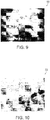
- Figure 9 show at 50 an in situ formed conductive structure as per this invention.
- Figure 9 shows a 10X view looking down from the top of a conductive structure.
- the dark areas are the agglomerated particles the lighter area represents particle poor areas, i.e., places from which particles migrated.
- This particle migration effect can be shown in more detail by looking at Figure 10 , which shows at 52 a 100X magnification of a conductive structure, again looking down from the top, but focused more towards the edge, showing the lighter, particle poor, areas.
- the clear material is the continuous medium, in this case a PSA, FLEXcon's V-95 acrylic adhesive. Note the striations or grooves in the clear V-95 acrylic adhesive, and also note that the few particles remaining are a lined with the striations.
- the starting material was a uniform particle distribution in continuous medium, thus under the electric field generated by the DOR test, the particles move together to form the conductive structure. Again, this agglomeration phenomenon may be referred to as electrophoretic or in the case of an AC electric field, dielectrophoretic effect, both of which are referred to herein as the electrophoretic process.
- the continuous medium is a dielectric and is in full contact with the conductive particles (at the particle loading levels) and the medium is a viscoelastic liquid, i.e., has a very high viscosity, five plus orders of magnitude higher (as measured in centipoises) than water dispersions (often measured in the only the 10s of centipoises).
- the DOR test involves a plane to plane electrode arrangement; after a few conductive structures are formed therefore, the electric field between the two electrodes is mostly dissipated due to the contacts already made between the electrodes.
- the first structure will form, where there is one spot where the two planes are closer to one another or there is an uneven distribution of carbon such that a slightly higher density of the conductive particles are at one increment, between the plane, in other words that point of least resistance.
- the testing of the stability of the in situ formed electrically conductive structures was accomplished by placing post DOR test samples in an oven at 160°F (71°C) for 16 hours and retesting the impedance (AAMI EC12-2000 - 4.2.2.1.) and signal receptive properties. In all cases the samples maintained the lower impedance.
- the conductive particles may be in the form of carbon, and may be provided in a concentration greater than 1% on solids, dry weight.
- a conductive layer such as conductive layers 26 and 28 of Figure 4
- a conductive layer that adjoins the composite for providing a voltage to an electrode, for example, does not need to be formed of an expensive material such as silver / silver chloride (Ag/AgCl) as is required with hydrogels.
- Hydrogels require such specialized conductive layers because the ionic conductivity of the hydrogel must ionically couple to the electrode.
- a conductive layer adjacent the composite may be formed of an inexpensive deposited layer (e.g., vacuum deposited or sputter coated) of, for example, conductive particles such as those discussed above but in a higher concentration to form a conductive layer upon deposition.
- Such less expensive materials may be used for the conductive layer because the mechanism for conduction is not ionic conductivity.
- a composite 60 may include particles having very large aspect ratios (upwards of 1000 to 1) such as carbon nanotubes 62 dispersed within a dielectric material 64 as shown in Figure 11 .
- particles having very large aspect ratios upwards of 1000 to 1
- the particles In the presence of an electric field that is applied in the Z direction (as shown at 66 in Figure 12 ), the particles agglomerate but because the particles are so long, they become entangled with one another when agglomeration occurs.
- an adhesive mixture including FLEXcon's V-95 acrylic adhesive, a polar material (Arquad HTL-8 sold by AkzoNobel, 20% solids on solids of the V-95 adhesive, and 0.04% single walled semi-conductive carbon nanotubes (CNTs).
- the mixture was provided in a 3% solids paste in a 72/28 solvent blend isopropyl alcohol / n-butyl alcohol (sold by Southwest Nanotechnologies of 2501 Technology Place, Norman, OK. The mixture was sonicated for 30 minutes to evenly disperse the CNTs throughout the adhesive/arquad premixture.
- the mixture was then coated, dried and cured as discussed above to a 2 mil (50 micron) dried thickness.
- the adhesive composites were made and tested as discussed above. The results were that the pre-DOR test (as per EC12-2000-4.2.2.1) showed an impedance of 100 k Ohms.
- the DOR test (as per EC12-2000-4.2.2.4) was pass, and that the impedance post EC12-2000-4.2.2.1 was 5 K Ohms.
- the signal receptivity was tested as in Example 1 to be both 95% before and after DOR.
- the anisotropy test as discussed above with respect to Example 3, found that there was an X and Y conductivity component to the composite post DOR. It is expected that more uniform istropic conductive coatings may be formed.
- a conductive polymeric contact material such as a sealing or attaching material to bring an EMF shield to ground
- new ways of making membrane switch devices may all benefit from composites of the present invention.
- Other applications that require or may benefit from a conformable electrical contact where the interface between the electrode and an active layer (such as in photovoltaics or organic light emitting diodes) may employ composites of the present invention.
- the possibility of using substantially lower concentrations of conductive particles such as nano-conductive particles provides the possibility of developing clear conductive coatings.
- the dielectric material (e.g., elastomer) of the adhesive component is present in high enough concentrations to flow out to make surface-to-surface contact between the substrates and an electrode, i.e., act as an adhesive.
- the dielectric material of Sample 1 the V-95 PSA and polar material
- the composite was then coated and dried onto a polyester based siliconized release liner to a 2 mil (50 micron) dry deposition.
- the resulting coating had substantially no measurable PSA properties (tack, peel, shear).
- An electrically conductive network however, had formed in the composite, and this composite was found to have a DC resistance of about 100 Ohms both before and after electrophoresis.
Abstract
Description
- The present application claims priority to
U.S. Patent Application Ser. No. 13/272,527 filed October 13, 2011 - The invention generally relates to conductive polymeric and elastomeric materials for use in a wide variety of applications, including without limitation, conductive adhesives, conductive gaskets and conductive films.
- The design of an electrically conductive pressure sensitive adhesive (PSA), for example, for has long presented challenges at least because adhesive strength and flexibility generally decrease with increased electrical conductivity. The materials that are typically used (added) to provide good electrical conductivity are generally less flexible and inhibit adhesion. A conventional way to prepare a conductive coating is to fill a polymeric material with conductive particles, e.g., graphite, silver, copper, etc., then coat, dry and cure the polymeric binder. In these cases the conductive particles are in such a concentration that there is a conductive network formed when the particles are each in physical contact with at least one other neighboring particle. In this way, a conductive path is provided through the composite.
- For pressure sensitive adhesives, however, if the particle concentration is high enough to form a network in which particle-to-particle contact is maintained then there is little chance that the polymer (e.g., elastomer) system of the PSA component is present in high enough concentrations to flow out to make surface-to-surface contact between the substrates and an electrode, i.e., act as an adhesive. Conversely, if the PSA component is sufficient concentration to make sufficient surface contact to the substrate, it would have to interrupt adjacent conductive particles such that particle-to-particle contact is disrupted.
- Another type of electrically conductive PSA includes conductive spherical particles with diameters equal to or greater than the thickness of the PSA. In this fashion the signal or current may be carried along the surface of the particles, thus providing current flow anisotropically in the z dimension of the adhesive. The continuity of the adhesive however, may be compromised.
- Salts, such as sodium or potassium chloride, readily dissolve when in an aqueous medium, and their ions dissociate (separate into positive and negative ions). The dissociated ions may then convey an electrical current or signal. For this reason, salts have long been added to water, which then may be added to polymeric and elastomeric materials, to provide good electrical conductivity. For example,
U.S. Patent No. 6,121,508 discloses a pressure sensitive adhesive hydrogel for use in a biomedical electrode. The gel material is disclosed to include at least water, potassium chloride and polyethylene glycol, and is disclosed to be electrically conductive.U.S. Patent No. 5,800,685 also discloses an electrically conductive adhesive hydrogel that includes water, salt, an initiator or catalyst and a cross linking agent. The use of such hydrogels however, also generally requires the use of a conductive surface at one side of the hydrogel (away from the patient) that is capable of receiving the ionically conductive charge, such as silver / silver chloride, which is relatively expensive. - While these hydrogel/adhesives can have good electrically conductive properties, they often have only fair adhesion properties. Another downside is that the electrical conductivity changes with changing water content, such as changes caused by evaporation, requiring that the hydrogels be maintained in a sealed environment prior to use, and then used for a limited period of time only due to evaporation.
-
U.S. Patent No. 7,651,638 discloses a water insensitive alternating current responsive composite that includes a polymeric material and a polar material (such as an organo salt) that is substantially dispersed within the polymeric material. The polymeric material and the polar material are chosen such that they each exhibit a mutual attraction that is substantially the same as the attraction to itself. Because of this, the polar material neither clumps together nor blooms to a surface of the polymeric material, but remains suspended within the polymeric material. This is in contrast to the use of salts in other applications that is intended to bloom to the surface (to provide a conductive layer along a surface, e.g., for static discharge) - The composites of
U.S. Patent No. 7,651,638 , however, remain dielectrics and have high resistance, and are therefore not suitable for use in certain applications, such as providing electrical stimulus to a human subject (such as is required during defibrillation and / or Transcutaneous Electrical Nerve Stimulation, etc.) due to the high resistance of the material. While such composites may be used for detecting small biological electric signals from a patient, a problem therefore, can arise when a patient undergoes a defibrillation procedure because the high resistance could prevent the charge overload from dissipating in a timely enough fashion as per AAMI EC12-2000 - 4.2.2.4, which is directed to defibrillation overload recovery (DOR). This failure to dissipate the charge may lead to uncertainty as to whether or not the defibrillation procedure has corrected the distress and therefore whether any further charge needs to be given to the patient. -
U.S. Patent No. 5,082,595 discloses an electrically conductive pressure sensitive adhesive that includes carbon particles, and the conductive adhesive is disclosed to be prepared by incorporating black filler (carbon) into the pressure sensitive adhesive in such a manner as to impart electrical conductivity, yet have a concentration low enough to avoid adversely affecting the physical properties (such as tack) of the adhesive. In particular, this patent states that a slurry of the carbon black in an organic solvent is formed under mild agitation or stirring in the absence of high shear to preserve the structures carbon black may form and to improve wetting of the carbon black. Such a composite, however, may not provide sufficient adhesiveness and conductivity in certain applications. Nor may such structures be discreetly placed to form conduction sites only at specific locations within a continuous adhesive. - There remains a need therefore, for a composite for use as a conductive polymeric material that provides electrical conductivity without compromising the desired properties of the polymeric material.
- In accordance with an embodiment, the invention provides a method of forming an electrically conductive composite comprising the steps of providing a first dielectric material and a second conductive material that is substantially dispersed within the first dielectric material; and applying an electric field through at least a portion of the combined first dielectric material and second conductive material such that the second conductive material undergoes electrophoresis and forms at least one electrically conductive path through the composite along the direction of the applied electric field.
- In accordance with another embodiment, the invention provides an electrically conductive material comprising a dielectric material and conductive particles within the dielectric material, wherein the conductive particles are aligned to form conductive paths through the composite by electrophoresis.
- In accordance with further embodiments, the dielectric material may be a pressure sensitive adhesive, the conductive particles may be formed of any of carbon powder, flakes, granules or nanotubes, and the conductive particles may have densities within the range of about 0.35 g/cm3 and about 1.20 g/cm3.
- The following description may be further understood with reference to the accompanying drawings in which:
-
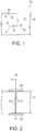
Figure 1 shows an illustrative diagrammatic view of a composite in accordance with an embodiment of the invention prior to electrophoresis; -
Figure 2 shows an illustrative diagrammatic view of the composite ofFigure 1 in the presence of an electric field sufficient to cause electrophoresis in the composite; -
Figure 3 shows an illustrative diagrammatic view of the composite ofFigure 2 after the electric field has been applied and removed; -
Figure 4 shows an illustrative diagrammatic view of the composite ofFigure 3 used for conducting electricity from one side of the composite to the other side of the composite; -
Figures 5A - 5C show illustrative diagrammatic views of the composite ofFigure 1 at successive moments after a direct current (DC) overcharge electric field is applied showing the electrophoresis activity; -
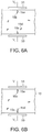
Figures 6A and 6B show illustrative diagrammatic views of the composite ofFigure 1 at successive moments after an alternating current (AC) overcharge electric field is applied showing the electrophoresis activity; -
Figures 7 and 8 show illustrative diagrammatic views of the conductive pathways formed in the polymeric material; -
Figures 9 and 10 show illustrative micro-photographic views of composites of the invention at different magnifications; and -
Figures 11 and 12 show illustrative diagrammatic views of composites of a further embodiment of the invention before and after electrophoresis providing electrical conductivity in multiple dimensions. - The drawings are shown for illustrative purposes only and are not to scale.
- Applicants have discovered that conductive materials may be formed by electrophoresis whereby conductive particles (e.g., 5% by weight carbon particles) within a dielectric material (e.g., a pressure sensitive adhesive) migrate when subjected to an electric field by aligning with the field to form conductive pathways through the composite.
- The requirements for the dielectric material (e.g., polymeric material) and the conductive material include that the materials interact in such a way that the conductive material does not bloom to a surface of the binder material. If conductive material has a surface energy greater than that of the dielectric material, then the conductive material should remain suspended within the dielectric material yet not be in sufficient concentrations to provide particle-to-particle electrical conductivity through the material prior to the application of an electric field.
-
Figure 1 for example, shows a composite 10 in accordance with an embodiment of the invention that includes adielectric material 12 andconductive particles 14 dispersed within thedielectric material 12. This may be achieved, for example, by introducing the conductive material (while dispersed in an evaporative continuous liquid phase) into the liquid polymeric material and then permitting the liquid phase of the dispersion of conductive particles to evaporate leaving the conductive material within the polymeric material. In accordance with an embodiment of the invention, the polymeric material may, for example, be an acrylic adhesive such as may be represented as
- As shown in
Figure 2 , when an electric field 18 (e.g., 5, 10, 50, 100, 200 volts or higher AC or DC) is applied to the composite atconductors conductive particles 14 undergo electrophoresis and will align with the electric field, forming a conductive path through the composite. As shown inFigure 3 , when the field is removed, theconductive particles 14 remain in place forming the conductive path. The composite may then be used to conduct electricity between, forexample conductors Figure 4 . - The conductive particles should have a surface energy that is at least slightly greater than that of the dielectric material to ensure that the dielectric material sufficiently wets the surface of the conductive particles. The density and surface area of the conductivity of the
particles 14 are important considerations. Applicants have found, for example, that carbon (e.g., graphite powder, flakes, granules, nanotubes etc.) having densities in the range of, for example, about 0.35 g/cm3 to about 1.20 g/cm3, and preferably between about 0.5 g/cm3 to 1.0 g/cm3, are suitable for use as the conductive material. The surface energy of the graphite is, again, preferably higher than that of the dielectric to ensure sufficient wetting of the surfaces of theparticles 14. In the above example, the graphite particles have a specific surface energy of 55 dynes/cm and the dielectric disclosed above has a surface energy of a little less than 40 dynes/cm. -
Figures 5A - 5C show the process of the electrophoresis that occurs upon overcharging in more detail. As shown inFigure 5A , when a DC voltage potential is applied, e.g., 5, 10, 50, 100 or 200 volts or higher, aparticle 14a that is near the surface aligns in the z-direction. Once this occurs, theinner end 16a of theparticle 14a is now closer to the opposing surface (as also shown inFigure 5A ), causing the charge on theinner end 16a to be slightly higher than the charge on the surrounding inner surface of the composite. This causes anothernearby particle 14b to be attracted to theinner end 16a of theparticle 14a as shown inFigure 5B . The inner end of theparticle 14b is now highly charged, causingnearby particle 14c to be attracted to it as shown inFigure 5C . Further particles (e.g., 14d as shown) are further attracted to the ends of the thus formed path. This all occurs rapidly and the attractive/aligning force causing the electrophoresis is believed to become stronger as the path is formed. - As shown in
Figure 6A , when an AC voltage is applied (again, e.g., 5, 10, 50, 100 or 200 volts or higher), theparticles first conductor 31. When a positive voltage charge is then applied at theopposite conductor 33, theconductive particles Figure 6B . By thus alternating the agglomeration process between opposite sides, the AC overvoltage causes a path to be formed that essentially meets in the middle. - Regardless of whether the charge is DC or AC, the higher the voltage, the faster the particles align, and with a relatively low voltage (e.g., about 5 volts or higher), the particles align more slowly, but do still eventually align. This agglomeration phenomenon may be referred to as electrophoretic (in the presence of a DC field) or dielectrophoretic (in the presence of an AC field), both of which are referred to herein as an electrophoresis process.
- As shown in
Figure 7 , following application of a voltage as discussed above over a small area of the composite, multiple conductive paths 38 will be formed through the composite, wherein each conductive path is formed by aligned conductive particles. As shown inFigure 8 , groups of suchconductive paths other areas 46 of the composite exhibit a high dielectric constant and are therefore not electrically conductive. - In accordance with an embodiment, in one example, to a liquid sample of FLEXcon's V-95 acrylic PSA was added 5% by weight (solids of the V-95 FLEXcon and Arquad blend) of a carbon particle (the Aquablack 5909 carbon particles from Solution Dispersions Inc., Cynthiana KY), which was uniformly dispersed within the polymer. This mixture was coated onto a 2 mil (50 micron) siliconized one side PET film, dried and cured for 10 min in a 160°F vented laboratory oven, to a dried deposition of 2 mil (50 micron). Upon placing the carbon particle in the V-95 acrylic adhesive composite between two electrodes, and electrically charging the electrodes, conductive structures were formed. It has further been found that the composite has a Z dimension directionality to the signal receptivity. This maintenance of Z dimensionality allows this adhesive to be used in applications as disclosed in
U.S. Patent Application Publication No. 2010-0036230 (the disclosure of which is hereby incorporated by reference in its entirety), which teaches the formation of a bio-sensor array fashioned with one continuous layer of adhesive, the disclosure of which is hereby incorporated by reference in its entirety. - Composites in accordance with certain embodiments of the present invention, begin with substantially separated particles uniformly dispersed within, for example, an adhesive. In a subsequent step, an electric field is applied to form the conductive structures. This is a decided advantage as it allows the placement of conductive structures in the Z dimension at specific X,Y, locations thus allowing for a specific point to point electrical contact.
- Again, with reference to
Figure 7 , multipleparallel paths 48 may be formed simultaneously upon application of a wide electric field. The distance between the paths will depend on the thickness of thematerial 12 and the concentration of conductive particles as well as any surface irregularities on the outer surfaces of thematerial 12. As shown inFigure 8 , discrete sets ofsuch paths non-conductive portions 46 there-between through application of electric fields in discrete areas (adjacent sets ofpaths - The following Examples demonstrate the effect of the conductive particle addition to the binder material discussed above.
- To a liquid sample of FLEXcon's V-95 acrylic PSA, is added a polar material, Arquad HTL-8 (AkzoNobel), 20% by weight on solids, to this 5% by weight (solids of the V-95 and Arquad blend) of a carbon particle (Aquablack 5909 from Solution Dispersions Inc., Cynthiana KY), which was uniformly dispersed and was designated as Sample 1. This mixture was coated on a 2 mil (50 micron) siliconized one side PET film, dried and cured for 10 min in a 160°F vented laboratory oven, to a dried deposition of 2 mil (50 micron).
- Also prepared at this time was the composite of just the V-95 acrylic adhesive and the Arquad (20% by solids weight), no carbon, as per the disclosure in
U.S. Patent No. 7,651,638 (the disclosure of which is hereby incorporated by reference in its entirety), and was designated as Sample 2. - This mixture was also 2 mil (50 microns) siliconized on one side of a PET film, dried and cured for 10min in a 160°F vented laboratory oven, to a dried deposition of 2 mil (50 microns) and was designated as Sample 2.
- Similarly a third sample was prepared consisting of only V-95 acrylic adhesive and 5% carbon, no polar material (Arquad), processed in the same manner as for samples 1 and 2, and was designated as Sample 3.
- All three samples were tested on a conductive base material consisting of a carbon filled polymeric film with a surface resistance of ∼100 ohms/square, using the experimental product designated EXV-215, 90PFW (as sold by FLEXcon Company, Inc. of Spencer, Massachusetts). The samples were tested using a QuadTech LCR Model 1900 testing device sold by QuadTech, Inc. of Marlborough, MA.
- In particular, all three samples were tested as per AAMI EC12-2000 - 4.2.2.1 (modified) and AAMI EC12-2000 - 4.2.2.4. The AAMI EC12-2000 - 4.2.2.1 test has an upper limit of 3000 Ohms for the face to face double adhesive part of the test, for a single point and a max average (12 test samples) of 2000 Ohms.
- The AAMI EC12-2000 - 4.2.2.4 calls for retaining less than 100 mV in 5 sec after a 200 DC volt charge, again using a face to double adhesive layer.
- Note the Table 1 below, which shows impedance (EC 12-2000 - 4.2.2.1) tested first; DOR (EC 12 - 2000 - 4.2.2.4) was run next on the same samples.
TABLE 1 Sample EC12-2000-4.2.2.1 (20 Hz) EC12-2000-4.2.2.4 Sample 1 60 K Ohms (fail) 0.0 volts in less than 5 sec. (pass Sample 2 80 K Ohms (fail) 150 volts after 5 sec. (fail) Sample 3 40 M Ohms (fail) 0.0 volts in less than 5 sec. (pass) - To determine the signal receptivity of this invention, the samples prepared for Example 1 were tested in accordance to the procedure outlined below. The samples used in testing as per AAMI EC12-2000 - 4.2.2.1 were used connected in series to a Wave Form Generator (Hewlett Packard 33120A 15MHz Function/Arbitrary Waveform Generator) and in series an Oscilloscope (BK Precision 100MHz Oscilloscope 2190). Samples were tested at 3, 10 and 100 Hz; results are given below in Table 2 in % of transmitted signal received.
TABLE 2 Sample 1 Sample 2 Sample 3 3 Hz 95+% 95% No signal 10 Hz 95+% 95% No signal 100 Hz 95+% 95% No signal - Samples that passed the DOR test (AAMI EC12-2000 - 4.2.2.4) were retested for impedance as per AAMI EC12-2000 - 4.2.2.1 (modified), upon rechecking, samples 1 & 3 had a remarkable change. Samples 1 and 3 now had an impedance of less than 1 K Ohms. In sample 2, the signal receptive medium was unchanged post DOR test; only those samples with the dispersed conductive particles changed. Further, the resulting lower impedance was still anisotropic, i.e., in the Z direction (noting Example 4 as to how the anisotropic property was determined). In addition the parallel capacitance (CP) of the post DOR material actually increases as the Z impedance decreases, as shown below in Table 3.
TABLE 3 Ohms (Z direction) CP Farads DC Resistance Ohms Sample 1 pre-DOR 60 K 11.0 nF 80 K Sample 1 post-DOR 860 61.6 nF 790 Sample 3 pre-DOR 13 M 0.06 nF 100+ M Sample 3 post-DOR 1.9 K 41.2 nF 1.45 K - The anisotropic property was validated by the following test procedure. Signals at 3, 10, 100, Hz were generated, and fed to a first copper shunt, which was placed on the conductive adhesive. A second copper shunt was placed on the same conductive adhesive ∼0.004" (100 microns) apart from the first shunt, which was connected (in series) to an oscilloscope. The base substrate was a dielectric material (PET film)
- If the Sample 1 adhesive was isotropic it would have been expected to pick up a signal on the oscilloscope. If the Sample 1 adhesive was anisotropic it would have been expected that no signal would be received on the oscilloscope. The result was that no signal was detected.
- The electrophoresis result does not appear to rely on the presence of the polar material in the composite. It is believed that the carbon particles are agglomerated by the electric field applied during the DOR test; that the electric field generated by the 200 DC volts being applied across the conductive particle containing SRM and/or the conductive particles just with a PSA (no polar organo-salt), is sufficient to cause the particles to agglomerate together, possibly by inducing an opposite charge on nearby particles.
- The agglomerated structures spanning from one electrode to the other are the reason an anisotropic conductive PSA is formed. To examine these agglomerations, reference is made to
Figure 9 , which show at 50 an in situ formed conductive structure as per this invention. In particular,Figure 9 shows a 10X view looking down from the top of a conductive structure. The dark areas are the agglomerated particles the lighter area represents particle poor areas, i.e., places from which particles migrated. - This particle migration effect can be shown in more detail by looking at
Figure 10 , which shows at 52 a 100X magnification of a conductive structure, again looking down from the top, but focused more towards the edge, showing the lighter, particle poor, areas. The clear material is the continuous medium, in this case a PSA, FLEXcon's V-95 acrylic adhesive. Note the striations or grooves in the clear V-95 acrylic adhesive, and also note that the few particles remaining are a lined with the striations. The starting material was a uniform particle distribution in continuous medium, thus under the electric field generated by the DOR test, the particles move together to form the conductive structure. Again, this agglomeration phenomenon may be referred to as electrophoretic or in the case of an AC electric field, dielectrophoretic effect, both of which are referred to herein as the electrophoretic process. - It is significant however, that in this case the agglomeration occurs in a nonaqueous high viscosity medium. In accordance with the present invention, the continuous medium is a dielectric and is in full contact with the conductive particles (at the particle loading levels) and the medium is a viscoelastic liquid, i.e., has a very high viscosity, five plus orders of magnitude higher (as measured in centipoises) than water dispersions (often measured in the only the 10s of centipoises).
- Again, what is postulated here is that, as in the case of particle agglomeration via an electric field in an aqueous continuous medium, a slight charge is induced on a nearby particle near an electrode. With the continuous medium being less polar and more dielectric than water however, a greater charge build-up can occur on a particle in the electric field.
- With water as the continuous medium the higher polarity would mitigate the charge build up, further if the applied electric field were increased (higher voltage) electrolysis of the water would become a competing complication. With a PSA (e.g., FLEXcon's V-95 acrylic adhesive) as the continuous medium there is much less charge mitigation and no substantial electro-chemical process that occurs.
- This charge build-up on the particle increases the attractive forces between the particle and the electrode, thus drawing the particle to the electrode in spite of the higher viscosity of the continuous medium. Further, the first particle that reaches the electrode forms an incremental high spot on said electrode thus the electric field is moved closer to the other electrode, as more particles join the agglomeration the field strength increase as the distance to the opposite electrode decreases, thus accelerating the agglomeration growth.
- The DOR test involves a plane to plane electrode arrangement; after a few conductive structures are formed therefore, the electric field between the two electrodes is mostly dissipated due to the contacts already made between the electrodes. Thus the first structure will form, where there is one spot where the two planes are closer to one another or there is an uneven distribution of carbon such that a slightly higher density of the conductive particles are at one increment, between the plane, in other words that point of least resistance.
- As a result using the plane to plane method in forming these structures has some limits as to the position and number of conductive structures formed. When a point-to-plane or point-to-point method is used to introduce the electric field however, more discrete in position and number of conductive structures would be formed as each point has its own electric field which is not readily dissipated when nearby conductive structures are formed.
- This was demonstrated by using a lab corona treating device on a conductive substrate that was grounded. The corona treating device acted like a series of point sources to a plane receiving substrate. What resulted was a uniformly distributed conductive structure across the surface of the adhesive.
- The testing of the stability of the in situ formed electrically conductive structures was accomplished by placing post DOR test samples in an oven at 160°F (71°C) for 16 hours and retesting the impedance (AAMI EC12-2000 - 4.2.2.1.) and signal receptive properties. In all cases the samples maintained the lower impedance. The conductive particles may be in the form of carbon, and may be provided in a concentration greater than 1% on solids, dry weight.
- The use of the composites of the present invention further provides that a conductive layer (such as
conductive layers Figure 4 ) that adjoins the composite for providing a voltage to an electrode, for example, does not need to be formed of an expensive material such as silver / silver chloride (Ag/AgCl) as is required with hydrogels. Hydrogels require such specialized conductive layers because the ionic conductivity of the hydrogel must ionically couple to the electrode. In accordance with the present invention on the other hand, a conductive layer adjacent the composite may be formed of an inexpensive deposited layer (e.g., vacuum deposited or sputter coated) of, for example, conductive particles such as those discussed above but in a higher concentration to form a conductive layer upon deposition. Such less expensive materials may be used for the conductive layer because the mechanism for conduction is not ionic conductivity. - As shown in
Figure 11 ,composites of further embodiments of the invention may undergo electrophoresis in multiple directions. For example, a composite 60 may include particles having very large aspect ratios (upwards of 1000 to 1) such ascarbon nanotubes 62 dispersed within adielectric material 64 as shown inFigure 11 . In the presence of an electric field that is applied in the Z direction (as shown at 66 inFigure 12 ), the particles agglomerate but because the particles are so long, they become entangled with one another when agglomeration occurs. This results in the particles not only providing electrical conductivity in the Z direction, but also providing electrical conductivity in the X and Y directions as well due to the entangled mass of particles extending in the X and Y directions as well as the Z direction as shown inFigure 12 . - In accordance with a further example therefore, an adhesive mixture including FLEXcon's V-95 acrylic adhesive, a polar material (Arquad HTL-8 sold by AkzoNobel, 20% solids on solids of the V-95 adhesive, and 0.04% single walled semi-conductive carbon nanotubes (CNTs). The mixture was provided in a 3% solids paste in a 72/28 solvent blend isopropyl alcohol / n-butyl alcohol (sold by Southwest Nanotechnologies of 2501 Technology Place, Norman, OK. The mixture was sonicated for 30 minutes to evenly disperse the CNTs throughout the adhesive/arquad premixture.
- The mixture was then coated, dried and cured as discussed above to a 2 mil (50 micron) dried thickness. The adhesive composites were made and tested as discussed above. The results were that the pre-DOR test (as per EC12-2000-4.2.2.1) showed an impedance of 100 k Ohms. The DOR test (as per EC12-2000-4.2.2.4) was pass, and that the impedance post EC12-2000-4.2.2.1 was 5 K Ohms. The signal receptivity was tested as in Example 1 to be both 95% before and after DOR. The anisotropy test as discussed above with respect to Example 3, found that there was an X and Y conductivity component to the composite post DOR. It is expected that more uniform istropic conductive coatings may be formed.
- Applications calling for a conductive polymeric contact material such as a sealing or attaching material to bring an EMF shield to ground, and new ways of making membrane switch devices may all benefit from composites of the present invention. Other applications that require or may benefit from a conformable electrical contact where the interface between the electrode and an active layer (such as in photovoltaics or organic light emitting diodes) may employ composites of the present invention. Moreover, the possibility of using substantially lower concentrations of conductive particles such as nano-conductive particles, provides the possibility of developing clear conductive coatings.
- As noted above, for pressure sensitive adhesives, if the particle concentration is high enough to form a network in which particle-to-particle contact is maintained then there is little chance that the dielectric material (e.g., elastomer) of the adhesive component is present in high enough concentrations to flow out to make surface-to-surface contact between the substrates and an electrode, i.e., act as an adhesive. In a further example, to the dielectric material of Sample 1 (the V-95 PSA and polar material) was added 25% by weight of the carbon particles of Sample 1. The composite was then coated and dried onto a polyester based siliconized release liner to a 2 mil (50 micron) dry deposition. The resulting coating had substantially no measurable PSA properties (tack, peel, shear). An electrically conductive network, however, had formed in the composite, and this composite was found to have a DC resistance of about 100 Ohms both before and after electrophoresis.
- Those skilled in the art will appreciate that numerous modifications and variations may be made to the above disclosed embodiments without departing from the spirit and scope of the present invention.
- For the avoidance of doubt, the present application extends to the subject-matter described in the following numbered paragraphs (referred to as "Para" or "Paras"):
- 1. A method of forming an electrically conductive composite comprising the steps of:
- providing a first dielectric material and a second conductive material that is substantially dispersed within the first dielectric material; and
- applying an electric field through at least a portion of the combined first dielectric material and second conductive material such that the second conductive material undergoes electrophoresis and forms at least one electrically conductive path through the electrically conductive composite along the direction of the applied electric field.
- 2. The method as claimed in Para 1, wherein said first dielectric material includes a polymeric material.
- 3. The method as claimed in Para 1, wherein said second conductive material includes particles formed any of carbon powder, flakes, granules or nanotubes.
- 4. The method as claimed in Para 3, wherein the carbon is in the form of graphite.
- 5. The method as claimed in Para 1, wherein said second conductive material includes particles having densities within the range of about 0.35 g/cm3 and about 1.20 g/cm3.
- 6. The method as claimed in Para 1, wherein said electrically conductive particles have densities within the range of about 0.5 g/cm3 and about 1.0 g/cm3.
- 7. The method as claimed in Para 1, wherein a surface energy of the second conductive material is higher than a surface energy of the first dielectric material.
- 8. The method as claimed in Para 1, wherein the conductive particles are randomly distributed within the composite prior to application of the electric field.
- 9. The method as claimed in Para 1, wherein said step of applying an electric field through at least a portion of the combined first dielectric material and second conductive material such that the second conductive material undergoes electrophoresis, forms a plurality of independent conductive paths through the electrically conductive composite along the direction of the applied electric field.
- 10. An electrically conductive material comprising a dielectric material and conductive particles within the dielectric material, wherein the conductive particles are aligned to form conductive paths through the composite by electrophoresis.
- 11. The electrically conductive material as claimed in
Para 10, wherein said dielectric material includes a polymeric material. - 12. The electrically conductive material as claimed in Para 11, wherein said dielectric material includes a pressure sensitive adhesive.
- 13. The electrically conductive material as claimed in Para 11, wherein said conductive particles are formed any of carbon powder, flakes, granules or nanotubes.
- 14. The electrically conductive material as claimed in Para 13, wherein the carbon is in the form of graphite.
- 15. The electrically conductive material as claimed in
Para 10, wherein said conductive particles have densities within the range of about 0.35 g/cm3 and about 1.20 g/cm3. - 16. The electrically conductive material as claimed in
Para 10, wherein said electrically conductive particles have densities within the range of about 0.5 g/cm3 and about 1.0 g/cm3. - 17. The electrically conductive material as claimed in
Para 10, wherein a surface energy of the conductive particles is higher than a surface energy of the dielectric material. - 18. The electrically conductive material as claimed in
Para 10, wherein the conductive particles are randomly distributed within the dielectric prior to application of an electric field. - 19. The electrically conductive material as claimed in
Para 10, wherein said material includes a plurality of electrically conductive paths formed by the conductive particles, where the plurality of electrically conductive paths are formed within an agglomerated mass of entangled conductive particles. - 20. The electrically conductive material as claimed in
Para 10, wherein said material includes a conductive layer for contacting an electrode, and the conductive layer includes no silver / silver chloride.
Claims (15)
- An electrically conductive composite comprising a viscoelastic dielectric material and conductive particles within the viscoelastic dielectric material, wherein the conductive particles are aligned to form conductive paths through the electrically conductive composite by electrophoresis.
- The electrically conductive composite as claimed in claim 1, wherein said viscoelastic dielectric material includes a polymeric material.
- The electrically conductive composite as claimed in claim 2, wherein said viscoelastic dielectric material includes a pressure sensitive adhesive.
- The electrically conductive composite as claimed in claim 2, wherein said conductive particles are formed any of carbon powder, flakes, granules or nanotubes.
- The electrically conductive composite as claimed in claim 4, wherein the carbon is in the form of graphite.
- The electrically conductive composite as claimed in claim 1, wherein said conductive particles have densities within the range of about 0.35 g/cm3 and about 1.20 g/cm3.
- The electrically conductive composite as claimed in claim 1, wherein said electrically conductive particles have densities within the range of about 0.5 g/cm3 and about 1.0 g/cm3.
- The electrically conductive composite as claimed in claim 1, wherein a surface energy of the conductive particles is higher than a surface energy of the viscoelastic dielectric material.
- The electrically conductive composite as claimed in claim 1, wherein the conductive particles are randomly distributed within the viscoelastic dielectric material prior to application of an electric field.
- The electrically conductive composite as claimed in claim 1, wherein said composite includes a plurality of electrically conductive paths formed by the conductive particles, where the plurality of electrically conductive paths are formed within an agglomerated mass of entangled conductive particles.
- The electrically conductive composite as claimed in claim 10, wherein the plurality of electrically conductive paths are formed in contiguous dielectric material that includes the viscoelastic dielectric material.
- The electrically conductive composite as claimed in claim 1, wherein said composite includes a conductive layer for contacting an electrode, and the conductive layer includes no silver/silver chloride.
- The electrically conductive composite as claimed in claim 1, wherein the electrically conductive composite further includes a polar material.
- The electrically conductive composite as claimed in claim 13, wherein the polar material includes an organic salt.
- The electrically conductive composite as claimed in claim 1, wherein the conductive particles remain aligned without the use of any curing agent.
Applications Claiming Priority (3)
| Application Number | Priority Date | Filing Date | Title |
|---|---|---|---|
| US13/272,527 US9818499B2 (en) | 2011-10-13 | 2011-10-13 | Electrically conductive materials formed by electrophoresis |
| EP12788335.3A EP2777051B1 (en) | 2011-10-13 | 2012-10-11 | Electrically conductive materials formed by electrophoresis |
| PCT/US2012/059650 WO2013055854A2 (en) | 2011-10-13 | 2012-10-11 | Electrically conductive materials formed by electrophoresis |
Related Parent Applications (1)
| Application Number | Title | Priority Date | Filing Date |
|---|---|---|---|
| EP12788335.3A Division EP2777051B1 (en) | 2011-10-13 | 2012-10-11 | Electrically conductive materials formed by electrophoresis |
Publications (2)
| Publication Number | Publication Date |
|---|---|
| EP3157018A1 true EP3157018A1 (en) | 2017-04-19 |
| EP3157018B1 EP3157018B1 (en) | 2019-04-17 |
Family
ID=47215729
Family Applications (2)
| Application Number | Title | Priority Date | Filing Date |
|---|---|---|---|
| EP12788335.3A Active EP2777051B1 (en) | 2011-10-13 | 2012-10-11 | Electrically conductive materials formed by electrophoresis |
| EP16188209.7A Active EP3157018B1 (en) | 2011-10-13 | 2012-10-11 | Electrically conductive materials formed by electrophoresis or dielectrophoresis |
Family Applications Before (1)
| Application Number | Title | Priority Date | Filing Date |
|---|---|---|---|
| EP12788335.3A Active EP2777051B1 (en) | 2011-10-13 | 2012-10-11 | Electrically conductive materials formed by electrophoresis |
Country Status (11)
| Country | Link |
|---|---|
| US (2) | US9818499B2 (en) |
| EP (2) | EP2777051B1 (en) |
| JP (2) | JP6063946B2 (en) |
| KR (2) | KR101842497B1 (en) |
| CN (1) | CN104094360B (en) |
| AU (2) | AU2012322863B2 (en) |
| CA (2) | CA2852023C (en) |
| DK (1) | DK2777051T3 (en) |
| ES (1) | ES2607642T3 (en) |
| PL (1) | PL2777051T3 (en) |
| WO (1) | WO2013055854A2 (en) |
Families Citing this family (17)
| Publication number | Priority date | Publication date | Assignee | Title |
|---|---|---|---|---|
| DE102011101579B4 (en) * | 2011-05-12 | 2015-03-05 | Otto Bock Healthcare Gmbh | Use of conductive polymer material for medical and orthopedic applications |
| US8673184B2 (en) * | 2011-10-13 | 2014-03-18 | Flexcon Company, Inc. | Systems and methods for providing overcharge protection in capacitive coupled biomedical electrodes |
| US20150282312A1 (en) * | 2013-03-15 | 2015-10-01 | Flexcon Company, Inc. | Systems and methods for providing surface connectivity of oriented conductive channels |
| US9775235B2 (en) * | 2013-03-15 | 2017-09-26 | Flexcon Company, Inc. | Systems and methods for providing surface connectivity of oriented conductive channels |
| US10177058B1 (en) * | 2018-01-26 | 2019-01-08 | Powertech Technology Inc. | Encapsulating composition, semiconductor package and manufacturing method thereof |
| FR3077676B1 (en) * | 2018-02-05 | 2021-05-14 | Linxens Holding | PROCESS FOR MANUFACTURING AN ELECTRICAL CIRCUIT INCLUDING AT LEAST ONE CONNECTOR FOR A CHIP CARD, AND ELECTRIC CIRCUIT OBTAINED, IN PARTICULAR, BY THIS PROCESS |
| CN109490735A (en) * | 2018-10-12 | 2019-03-19 | 上海谱幂精密仪器科技有限公司 | It is a kind of for measuring the device and method of electric current and/or voltage |
| KR20220014162A (en) * | 2020-07-28 | 2022-02-04 | 삼성전자주식회사 | Flexible printed circuit board assembly and electronic device comprising the same |
| US20230065587A1 (en) | 2021-08-31 | 2023-03-02 | Novocure Gmbh | Electrode assembly with a skin contact layer comprising a conductive adhesive composite, and systems and methods of applying tumor treating fields using same |
| US20230149704A1 (en) | 2021-11-17 | 2023-05-18 | Novocure Gmbh | Electrode Assembly with Non-Hydrogel Conductive Adhesive Layer and Methods of Applying Tumor Treating Fields Using Same |
| TW202327688A (en) | 2021-11-30 | 2023-07-16 | 瑞士商諾沃庫勒有限責任公司 | Devices, systems, and methods for applying tumor-treating fields |
| TW202332482A (en) | 2021-12-17 | 2023-08-16 | 瑞士商諾沃庫勒有限責任公司 | Systems and methods for removing and replacing conductive adhesive layers of an electrode array |
| TW202402344A (en) | 2022-03-31 | 2024-01-16 | 瑞士商諾沃庫勒有限責任公司 | Electrode assembly having perforated anisotropic layer, and systems and methods of applying tumor treating fields using same |
| US20230310850A1 (en) | 2022-03-31 | 2023-10-05 | Novocure Gmbh | Devices, Systems, And Methods For Applying Tumor-Treating Fields |
| WO2024003775A1 (en) | 2022-06-28 | 2024-01-04 | Novocure Gmbh | Apparatus comprising dielectric layer coupled to anisotropic layer |
| US20240100321A1 (en) | 2022-09-22 | 2024-03-28 | Novocure Gmbh | Electrode Assembly With Filler Structure Between Electrode Elements |
| WO2024069517A1 (en) | 2022-09-29 | 2024-04-04 | Novocure Gmbh | Flexible electrode arrays |
Citations (9)
| Publication number | Priority date | Publication date | Assignee | Title |
|---|---|---|---|---|
| US4170677A (en) * | 1977-11-16 | 1979-10-09 | The United States Of America As Represented By The Secretary Of The Army | Anisotropic resistance bonding technique |
| US5082595A (en) | 1990-01-31 | 1992-01-21 | Adhesives Research, Inc. | Method of making an electrically conductive pressure sensitive adhesive |
| US5800685A (en) | 1996-10-28 | 1998-09-01 | Cardiotronics Systems, Inc. | Electrically conductive adhesive hydrogels |
| US6121508A (en) | 1995-12-29 | 2000-09-19 | 3M Innovative Properties Company | Polar, lipophilic pressure-sensitive adhesive compositions and medical devices using same |
| US20070035808A1 (en) * | 2001-07-09 | 2007-02-15 | E Ink Corporation | Electro-optic display and materials for use therein |
| US20090038832A1 (en) * | 2007-08-10 | 2009-02-12 | Sterling Chaffins | Device and method of forming electrical path with carbon nanotubes |
| US7651638B2 (en) | 2002-04-10 | 2010-01-26 | Flexcon Company, Inc. | Hydro-insensitive alternating current responsive composites |
| US20100036230A1 (en) | 2008-08-06 | 2010-02-11 | Flexcon Company, Inc. | Multiple Electrode Composite Systems and Methods for Use in Electrocardiogram Detection Systems |
| NO20092381L (en) * | 2009-06-22 | 2010-12-23 | Inst Energiteknik | A method of making an anisotropic conductive layer and an object produced therefrom |
Family Cites Families (43)
| Publication number | Priority date | Publication date | Assignee | Title |
|---|---|---|---|---|
| US4188449A (en) | 1977-08-04 | 1980-02-12 | Eastman Kodak Company | Phosphorescent screens |
| US4417174A (en) | 1980-10-03 | 1983-11-22 | Alps Electric Co., Ltd. | Electroluminescent cell and method of producing the same |
| US4816717A (en) | 1984-02-06 | 1989-03-28 | Rogers Corporation | Electroluminescent lamp having a polymer phosphor layer formed in substantially a non-crossed linked state |
| US4548862A (en) | 1984-09-04 | 1985-10-22 | Minnesota Mining And Manufacturing Company | Flexible tape having bridges of electrically conductive particles extending across its pressure-sensitive adhesive layer |
| CN1011271B (en) | 1984-09-04 | 1991-01-16 | 明尼苏达矿业制造公司 | Flexible tape having bridges of electrically conductive particles extending across its pressure-sensitive adhesive layer |
| JPS6222383A (en) | 1985-07-22 | 1987-01-30 | 古河電気工業株式会社 | Connection of electric circuit member |
| US4687968A (en) | 1985-08-12 | 1987-08-18 | Rogers Corporation | Encapsulated electroluminescent lamp |
| US4852571A (en) | 1987-09-03 | 1989-08-01 | Marquette Electronics | Disposable biopotential electrode |
| CA2004530A1 (en) | 1988-12-16 | 1990-06-16 | Larry A. Nativi | Desiccant for el lamps |
| US5246782A (en) | 1990-12-10 | 1993-09-21 | The Dow Chemical Company | Laminates of polymers having perfluorocyclobutane rings and polymers containing perfluorocyclobutane rings |
| US5479070A (en) | 1990-05-18 | 1995-12-26 | Fuji Xerox Co., Ltd. | Light-emitting element device |
| US5321069A (en) | 1992-11-25 | 1994-06-14 | Afterglow Accent Yarns, Inc. | Process for producing phosphorescent yarn and yarn produced by the process |
| JPH0821469B2 (en) | 1993-06-28 | 1996-03-04 | 出光興産株式会社 | Method for sealing organic EL element and light emitting device obtained by this method |
| US5552679A (en) | 1993-07-15 | 1996-09-03 | International En-R-Tech Incorporated | Electroluminescent and light reflective panel |
| DE19630016C2 (en) | 1996-07-25 | 2000-10-12 | Daimler Chrysler Ag | Method for producing a phosphor layer of a cathode ray tube |
| ES2181178T3 (en) * | 1997-01-06 | 2003-02-16 | Kraton Polymers Res Bv | PRESSURE SENSITIVE ADHESIVES INCLUDING THERMOPLASTIC POLYURETHANS. |
| US6190509B1 (en) | 1997-03-04 | 2001-02-20 | Tessera, Inc. | Methods of making anisotropic conductive elements for use in microelectronic packaging |
| US5821691A (en) | 1997-03-14 | 1998-10-13 | Durel Corporation | EL panel with continuous contacts on back of panel |
| TW379513B (en) | 1997-04-17 | 2000-01-11 | Kureha Chemical Ind Co Ltd | Moisture-proof film and electro-luminescent element |
| EP1044585A4 (en) | 1998-01-06 | 2001-09-26 | Rogers Corp | Electroluminescent lamps having improved interfacial adhesion |
| US6207077B1 (en) | 2000-02-18 | 2001-03-27 | Orion 21 A.D. Pty Ltd | Luminescent gel coats and moldable resins |
| GB9824818D0 (en) | 1998-11-12 | 1999-01-06 | Zeneca Ltd | Composition,process and use |
| JP2000260561A (en) | 1999-03-05 | 2000-09-22 | Toshiba Corp | El panel |
| US6518359B1 (en) * | 2000-02-25 | 2003-02-11 | 3M Innovative Properties Co. | Polyurethane-based pressure-sensitive adhesives, systems for such adhesives, articles therefrom, and methods of making |
| GB2377819B (en) | 2000-03-24 | 2004-06-09 | World Properties Inc | Polymeric organic coatings and method of manufacture thereof |
| US7495384B2 (en) | 2000-08-29 | 2009-02-24 | Freelight Systems Limited | Display comprising a fluorescent dye doped polymer |
| US7112472B2 (en) * | 2003-06-25 | 2006-09-26 | Intel Corporation | Methods of fabricating a composite carbon nanotube thermal interface device |
| CN101382719B (en) | 2003-10-24 | 2012-04-04 | 伊英克公司 | Electro-optic displays |
| US7169250B2 (en) * | 2004-07-27 | 2007-01-30 | Motorola, Inc. | Nanofibrous articles |
| JP2006085998A (en) * | 2004-09-15 | 2006-03-30 | Nitto Denko Corp | Anisotropic conductive adhesive sheet and its manufacturing method |
| JP2007026776A (en) * | 2005-07-13 | 2007-02-01 | Sumitomo Electric Ind Ltd | Conductive fine particle and adhesive using the same |
| JP5129935B2 (en) * | 2006-06-13 | 2013-01-30 | 日東電工株式会社 | Sheet-like composite material and manufacturing method thereof |
| WO2008054759A2 (en) * | 2006-10-31 | 2008-05-08 | U Mass Dartmouth - Central | Fabric based laminar composite and method for manufacture thereof |
| US8706183B2 (en) | 2007-06-28 | 2014-04-22 | University Of Pittsburgh-Of The Commonwealth System Of Higher Education | Electrode systems, devices and methods |
| AU2009270810B2 (en) | 2008-07-18 | 2013-10-17 | Flexcon Company, Inc. | High impedance signal detection systems and methods for use in electrocardiogram detection systems |
| JP2010040893A (en) * | 2008-08-07 | 2010-02-18 | Sumitomo Bakelite Co Ltd | Method of connecting terminals to each other, method of manufacturing semiconductor device using the same, and method of coagulating conductive particle |
| US10090076B2 (en) * | 2009-06-22 | 2018-10-02 | Condalign As | Anisotropic conductive polymer material |
| US10071902B2 (en) | 2010-12-08 | 2018-09-11 | Condalign As | Method for assembling conductive particles into conductive pathways and sensors thus formed |
| EP2659063B1 (en) | 2010-12-15 | 2018-06-27 | Condalign AS | Method for forming an anisotropic conductive paper and a paper thus formed |
| CN103517958A (en) | 2010-12-15 | 2014-01-15 | 康达利恩股份公司 | Method for forming uv-curable conductive compositions and a domposition thus formed |
| WO2012085105A1 (en) | 2010-12-21 | 2012-06-28 | Condalign As | Battery electrode material and method for making the same |
| US20130276882A1 (en) | 2010-12-21 | 2013-10-24 | Condalign As | Method for forming conductive structures in a solar cell |
| US8673184B2 (en) * | 2011-10-13 | 2014-03-18 | Flexcon Company, Inc. | Systems and methods for providing overcharge protection in capacitive coupled biomedical electrodes |
-
2011
- 2011-10-13 US US13/272,527 patent/US9818499B2/en active Active
-
2012
- 2012-10-11 WO PCT/US2012/059650 patent/WO2013055854A2/en active Application Filing
- 2012-10-11 KR KR1020167034054A patent/KR101842497B1/en active IP Right Grant
- 2012-10-11 CA CA2852023A patent/CA2852023C/en active Active
- 2012-10-11 EP EP12788335.3A patent/EP2777051B1/en active Active
- 2012-10-11 CA CA2954837A patent/CA2954837C/en active Active
- 2012-10-11 AU AU2012322863A patent/AU2012322863B2/en active Active
- 2012-10-11 CN CN201280056619.3A patent/CN104094360B/en active Active
- 2012-10-11 DK DK12788335.3T patent/DK2777051T3/en active
- 2012-10-11 KR KR1020147012862A patent/KR20140128290A/en active Application Filing
- 2012-10-11 JP JP2014535851A patent/JP6063946B2/en active Active
- 2012-10-11 PL PL12788335T patent/PL2777051T3/en unknown
- 2012-10-11 EP EP16188209.7A patent/EP3157018B1/en active Active
- 2012-10-11 ES ES12788335.3T patent/ES2607642T3/en active Active
-
2015
- 2015-10-06 US US14/876,297 patent/US9947432B2/en active Active
-
2016
- 2016-04-14 AU AU2016202342A patent/AU2016202342B2/en active Active
- 2016-10-27 JP JP2016210378A patent/JP6320484B2/en active Active
Patent Citations (10)
| Publication number | Priority date | Publication date | Assignee | Title |
|---|---|---|---|---|
| US4170677A (en) * | 1977-11-16 | 1979-10-09 | The United States Of America As Represented By The Secretary Of The Army | Anisotropic resistance bonding technique |
| US5082595A (en) | 1990-01-31 | 1992-01-21 | Adhesives Research, Inc. | Method of making an electrically conductive pressure sensitive adhesive |
| US6121508A (en) | 1995-12-29 | 2000-09-19 | 3M Innovative Properties Company | Polar, lipophilic pressure-sensitive adhesive compositions and medical devices using same |
| US5800685A (en) | 1996-10-28 | 1998-09-01 | Cardiotronics Systems, Inc. | Electrically conductive adhesive hydrogels |
| US20070035808A1 (en) * | 2001-07-09 | 2007-02-15 | E Ink Corporation | Electro-optic display and materials for use therein |
| US7651638B2 (en) | 2002-04-10 | 2010-01-26 | Flexcon Company, Inc. | Hydro-insensitive alternating current responsive composites |
| US20090038832A1 (en) * | 2007-08-10 | 2009-02-12 | Sterling Chaffins | Device and method of forming electrical path with carbon nanotubes |
| US20100036230A1 (en) | 2008-08-06 | 2010-02-11 | Flexcon Company, Inc. | Multiple Electrode Composite Systems and Methods for Use in Electrocardiogram Detection Systems |
| NO20092381L (en) * | 2009-06-22 | 2010-12-23 | Inst Energiteknik | A method of making an anisotropic conductive layer and an object produced therefrom |
| US20120224285A1 (en) * | 2009-06-22 | 2012-09-06 | Condalign As, Instituttv. 18 | Electrostatic discharge device and method for manufacturing the same |
Also Published As
| Publication number | Publication date |
|---|---|
| WO2013055854A3 (en) | 2014-04-10 |
| CA2852023A1 (en) | 2013-04-18 |
| US20130092881A1 (en) | 2013-04-18 |
| AU2012322863B2 (en) | 2016-05-12 |
| AU2012322863A1 (en) | 2014-05-29 |
| WO2013055854A2 (en) | 2013-04-18 |
| JP2017095687A (en) | 2017-06-01 |
| EP2777051A2 (en) | 2014-09-17 |
| EP3157018B1 (en) | 2019-04-17 |
| KR20160142420A (en) | 2016-12-12 |
| CA2954837C (en) | 2020-06-16 |
| EP2777051B1 (en) | 2016-09-14 |
| DK2777051T3 (en) | 2017-01-09 |
| US20160027548A1 (en) | 2016-01-28 |
| KR20140128290A (en) | 2014-11-05 |
| PL2777051T3 (en) | 2017-05-31 |
| ES2607642T3 (en) | 2017-04-03 |
| AU2016202342A1 (en) | 2016-05-05 |
| AU2016202342B2 (en) | 2018-03-01 |
| CA2954837A1 (en) | 2013-04-18 |
| JP6063946B2 (en) | 2017-01-18 |
| CA2852023C (en) | 2017-03-21 |
| JP2015503178A (en) | 2015-01-29 |
| JP6320484B2 (en) | 2018-05-09 |
| CN104094360A (en) | 2014-10-08 |
| CN104094360B (en) | 2018-04-20 |
| KR101842497B1 (en) | 2018-03-27 |
| US9818499B2 (en) | 2017-11-14 |
| US9947432B2 (en) | 2018-04-17 |
Similar Documents
| Publication | Publication Date | Title |
|---|---|---|
| AU2016202342B2 (en) | Electrically conductive materials formed by electrophoresis | |
| CA2987188C (en) | Systems and methods for providing overcharge protection in capacitive coupled biomedical electrodes | |
| AU2014239280B2 (en) | Systems and methods for providing surface connectivity of oriented conductive channels |
Legal Events
| Date | Code | Title | Description |
|---|---|---|---|
| PUAI | Public reference made under article 153(3) epc to a published international application that has entered the european phase |
Free format text: ORIGINAL CODE: 0009012 |
|
| STAA | Information on the status of an ep patent application or granted ep patent |
Free format text: STATUS: THE APPLICATION HAS BEEN PUBLISHED |
|
| AC | Divisional application: reference to earlier application |
Ref document number: 2777051 Country of ref document: EP Kind code of ref document: P |
|
| AK | Designated contracting states |
Kind code of ref document: A1 Designated state(s): AL AT BE BG CH CY CZ DE DK EE ES FI FR GB GR HR HU IE IS IT LI LT LU LV MC MK MT NL NO PL PT RO RS SE SI SK SM TR |
|
| STAA | Information on the status of an ep patent application or granted ep patent |
Free format text: STATUS: REQUEST FOR EXAMINATION WAS MADE |
|
| 17P | Request for examination filed |
Effective date: 20171019 |
|
| RBV | Designated contracting states (corrected) |
Designated state(s): AL AT BE BG CH CY CZ DE DK EE ES FI FR GB GR HR HU IE IS IT LI LT LU LV MC MK MT NL NO PL PT RO RS SE SI SK SM TR |
|
| STAA | Information on the status of an ep patent application or granted ep patent |
Free format text: STATUS: EXAMINATION IS IN PROGRESS |
|
| 17Q | First examination report despatched |
Effective date: 20180426 |
|
| RIC1 | Information provided on ipc code assigned before grant |
Ipc: C09J 9/02 20060101ALI20180912BHEP Ipc: H01B 1/24 20060101AFI20180912BHEP Ipc: B82Y 30/00 20110101ALN20180912BHEP Ipc: H05K 1/09 20060101ALI20180912BHEP |
|
| GRAP | Despatch of communication of intention to grant a patent |
Free format text: ORIGINAL CODE: EPIDOSNIGR1 |
|
| STAA | Information on the status of an ep patent application or granted ep patent |
Free format text: STATUS: GRANT OF PATENT IS INTENDED |
|
| INTG | Intention to grant announced |
Effective date: 20181024 |
|
| GRAS | Grant fee paid |
Free format text: ORIGINAL CODE: EPIDOSNIGR3 |
|
| GRAA | (expected) grant |
Free format text: ORIGINAL CODE: 0009210 |
|
| STAA | Information on the status of an ep patent application or granted ep patent |
Free format text: STATUS: THE PATENT HAS BEEN GRANTED |
|
| AC | Divisional application: reference to earlier application |
Ref document number: 2777051 Country of ref document: EP Kind code of ref document: P |
|
| AK | Designated contracting states |
Kind code of ref document: B1 Designated state(s): AL AT BE BG CH CY CZ DE DK EE ES FI FR GB GR HR HU IE IS IT LI LT LU LV MC MK MT NL NO PL PT RO RS SE SI SK SM TR |
|
| REG | Reference to a national code |
Ref country code: GB Ref legal event code: FG4D |
|
| REG | Reference to a national code |
Ref country code: CH Ref legal event code: EP |
|
| REG | Reference to a national code |
Ref country code: DE Ref legal event code: R096 Ref document number: 602012059233 Country of ref document: DE |
|
| REG | Reference to a national code |
Ref country code: AT Ref legal event code: REF Ref document number: 1122451 Country of ref document: AT Kind code of ref document: T Effective date: 20190515 Ref country code: IE Ref legal event code: FG4D |
|
| REG | Reference to a national code |
Ref country code: NL Ref legal event code: MP Effective date: 20190417 |
|
| REG | Reference to a national code |
Ref country code: LT Ref legal event code: MG4D |
|
| PG25 | Lapsed in a contracting state [announced via postgrant information from national office to epo] |
Ref country code: NL Free format text: LAPSE BECAUSE OF FAILURE TO SUBMIT A TRANSLATION OF THE DESCRIPTION OR TO PAY THE FEE WITHIN THE PRESCRIBED TIME-LIMIT Effective date: 20190417 |
|
| PG25 | Lapsed in a contracting state [announced via postgrant information from national office to epo] |
Ref country code: FI Free format text: LAPSE BECAUSE OF FAILURE TO SUBMIT A TRANSLATION OF THE DESCRIPTION OR TO PAY THE FEE WITHIN THE PRESCRIBED TIME-LIMIT Effective date: 20190417 Ref country code: SE Free format text: LAPSE BECAUSE OF FAILURE TO SUBMIT A TRANSLATION OF THE DESCRIPTION OR TO PAY THE FEE WITHIN THE PRESCRIBED TIME-LIMIT Effective date: 20190417 Ref country code: ES Free format text: LAPSE BECAUSE OF FAILURE TO SUBMIT A TRANSLATION OF THE DESCRIPTION OR TO PAY THE FEE WITHIN THE PRESCRIBED TIME-LIMIT Effective date: 20190417 Ref country code: LT Free format text: LAPSE BECAUSE OF FAILURE TO SUBMIT A TRANSLATION OF THE DESCRIPTION OR TO PAY THE FEE WITHIN THE PRESCRIBED TIME-LIMIT Effective date: 20190417 Ref country code: AL Free format text: LAPSE BECAUSE OF FAILURE TO SUBMIT A TRANSLATION OF THE DESCRIPTION OR TO PAY THE FEE WITHIN THE PRESCRIBED TIME-LIMIT Effective date: 20190417 Ref country code: PT Free format text: LAPSE BECAUSE OF FAILURE TO SUBMIT A TRANSLATION OF THE DESCRIPTION OR TO PAY THE FEE WITHIN THE PRESCRIBED TIME-LIMIT Effective date: 20190817 Ref country code: HR Free format text: LAPSE BECAUSE OF FAILURE TO SUBMIT A TRANSLATION OF THE DESCRIPTION OR TO PAY THE FEE WITHIN THE PRESCRIBED TIME-LIMIT Effective date: 20190417 Ref country code: NO Free format text: LAPSE BECAUSE OF FAILURE TO SUBMIT A TRANSLATION OF THE DESCRIPTION OR TO PAY THE FEE WITHIN THE PRESCRIBED TIME-LIMIT Effective date: 20190717 |
|
| PG25 | Lapsed in a contracting state [announced via postgrant information from national office to epo] |
Ref country code: LV Free format text: LAPSE BECAUSE OF FAILURE TO SUBMIT A TRANSLATION OF THE DESCRIPTION OR TO PAY THE FEE WITHIN THE PRESCRIBED TIME-LIMIT Effective date: 20190417 Ref country code: PL Free format text: LAPSE BECAUSE OF FAILURE TO SUBMIT A TRANSLATION OF THE DESCRIPTION OR TO PAY THE FEE WITHIN THE PRESCRIBED TIME-LIMIT Effective date: 20190417 Ref country code: GR Free format text: LAPSE BECAUSE OF FAILURE TO SUBMIT A TRANSLATION OF THE DESCRIPTION OR TO PAY THE FEE WITHIN THE PRESCRIBED TIME-LIMIT Effective date: 20190718 Ref country code: BG Free format text: LAPSE BECAUSE OF FAILURE TO SUBMIT A TRANSLATION OF THE DESCRIPTION OR TO PAY THE FEE WITHIN THE PRESCRIBED TIME-LIMIT Effective date: 20190717 Ref country code: RS Free format text: LAPSE BECAUSE OF FAILURE TO SUBMIT A TRANSLATION OF THE DESCRIPTION OR TO PAY THE FEE WITHIN THE PRESCRIBED TIME-LIMIT Effective date: 20190417 |
|
| REG | Reference to a national code |
Ref country code: AT Ref legal event code: MK05 Ref document number: 1122451 Country of ref document: AT Kind code of ref document: T Effective date: 20190417 |
|
| PG25 | Lapsed in a contracting state [announced via postgrant information from national office to epo] |
Ref country code: IS Free format text: LAPSE BECAUSE OF FAILURE TO SUBMIT A TRANSLATION OF THE DESCRIPTION OR TO PAY THE FEE WITHIN THE PRESCRIBED TIME-LIMIT Effective date: 20190817 |
|
| REG | Reference to a national code |
Ref country code: DE Ref legal event code: R097 Ref document number: 602012059233 Country of ref document: DE |
|
| PG25 | Lapsed in a contracting state [announced via postgrant information from national office to epo] |
Ref country code: CZ Free format text: LAPSE BECAUSE OF FAILURE TO SUBMIT A TRANSLATION OF THE DESCRIPTION OR TO PAY THE FEE WITHIN THE PRESCRIBED TIME-LIMIT Effective date: 20190417 Ref country code: RO Free format text: LAPSE BECAUSE OF FAILURE TO SUBMIT A TRANSLATION OF THE DESCRIPTION OR TO PAY THE FEE WITHIN THE PRESCRIBED TIME-LIMIT Effective date: 20190417 Ref country code: SK Free format text: LAPSE BECAUSE OF FAILURE TO SUBMIT A TRANSLATION OF THE DESCRIPTION OR TO PAY THE FEE WITHIN THE PRESCRIBED TIME-LIMIT Effective date: 20190417 Ref country code: DK Free format text: LAPSE BECAUSE OF FAILURE TO SUBMIT A TRANSLATION OF THE DESCRIPTION OR TO PAY THE FEE WITHIN THE PRESCRIBED TIME-LIMIT Effective date: 20190417 Ref country code: EE Free format text: LAPSE BECAUSE OF FAILURE TO SUBMIT A TRANSLATION OF THE DESCRIPTION OR TO PAY THE FEE WITHIN THE PRESCRIBED TIME-LIMIT Effective date: 20190417 Ref country code: AT Free format text: LAPSE BECAUSE OF FAILURE TO SUBMIT A TRANSLATION OF THE DESCRIPTION OR TO PAY THE FEE WITHIN THE PRESCRIBED TIME-LIMIT Effective date: 20190417 |
|
| PLBE | No opposition filed within time limit |
Free format text: ORIGINAL CODE: 0009261 |
|
| STAA | Information on the status of an ep patent application or granted ep patent |
Free format text: STATUS: NO OPPOSITION FILED WITHIN TIME LIMIT |
|
| PG25 | Lapsed in a contracting state [announced via postgrant information from national office to epo] |
Ref country code: IT Free format text: LAPSE BECAUSE OF FAILURE TO SUBMIT A TRANSLATION OF THE DESCRIPTION OR TO PAY THE FEE WITHIN THE PRESCRIBED TIME-LIMIT Effective date: 20190417 Ref country code: SM Free format text: LAPSE BECAUSE OF FAILURE TO SUBMIT A TRANSLATION OF THE DESCRIPTION OR TO PAY THE FEE WITHIN THE PRESCRIBED TIME-LIMIT Effective date: 20190417 |
|
| 26N | No opposition filed |
Effective date: 20200120 |
|
| PG25 | Lapsed in a contracting state [announced via postgrant information from national office to epo] |
Ref country code: TR Free format text: LAPSE BECAUSE OF FAILURE TO SUBMIT A TRANSLATION OF THE DESCRIPTION OR TO PAY THE FEE WITHIN THE PRESCRIBED TIME-LIMIT Effective date: 20190417 |
|
| PG25 | Lapsed in a contracting state [announced via postgrant information from national office to epo] |
Ref country code: SI Free format text: LAPSE BECAUSE OF FAILURE TO SUBMIT A TRANSLATION OF THE DESCRIPTION OR TO PAY THE FEE WITHIN THE PRESCRIBED TIME-LIMIT Effective date: 20190417 Ref country code: MC Free format text: LAPSE BECAUSE OF FAILURE TO SUBMIT A TRANSLATION OF THE DESCRIPTION OR TO PAY THE FEE WITHIN THE PRESCRIBED TIME-LIMIT Effective date: 20190417 |
|
| REG | Reference to a national code |
Ref country code: CH Ref legal event code: PL |
|
| PG25 | Lapsed in a contracting state [announced via postgrant information from national office to epo] |
Ref country code: LU Free format text: LAPSE BECAUSE OF NON-PAYMENT OF DUE FEES Effective date: 20191011 Ref country code: LI Free format text: LAPSE BECAUSE OF NON-PAYMENT OF DUE FEES Effective date: 20191031 Ref country code: CH Free format text: LAPSE BECAUSE OF NON-PAYMENT OF DUE FEES Effective date: 20191031 |
|
| REG | Reference to a national code |
Ref country code: BE Ref legal event code: MM Effective date: 20191031 |
|
| PG25 | Lapsed in a contracting state [announced via postgrant information from national office to epo] |
Ref country code: BE Free format text: LAPSE BECAUSE OF NON-PAYMENT OF DUE FEES Effective date: 20191031 |
|
| PG25 | Lapsed in a contracting state [announced via postgrant information from national office to epo] |
Ref country code: IE Free format text: LAPSE BECAUSE OF NON-PAYMENT OF DUE FEES Effective date: 20191011 Ref country code: FR Free format text: LAPSE BECAUSE OF NON-PAYMENT OF DUE FEES Effective date: 20191031 |
|
| REG | Reference to a national code |
Ref country code: DE Ref legal event code: R082 Ref document number: 602012059233 Country of ref document: DE Representative=s name: HL KEMPNER PATENTANWAELTE, SOLICITORS (ENGLAND, DE Ref country code: DE Ref legal event code: R082 Ref document number: 602012059233 Country of ref document: DE Representative=s name: HL KEMPNER PATENTANWALT, RECHTSANWALT, SOLICIT, DE |
|
| PG25 | Lapsed in a contracting state [announced via postgrant information from national office to epo] |
Ref country code: CY Free format text: LAPSE BECAUSE OF FAILURE TO SUBMIT A TRANSLATION OF THE DESCRIPTION OR TO PAY THE FEE WITHIN THE PRESCRIBED TIME-LIMIT Effective date: 20190417 |
|
| PG25 | Lapsed in a contracting state [announced via postgrant information from national office to epo] |
Ref country code: HU Free format text: LAPSE BECAUSE OF FAILURE TO SUBMIT A TRANSLATION OF THE DESCRIPTION OR TO PAY THE FEE WITHIN THE PRESCRIBED TIME-LIMIT; INVALID AB INITIO Effective date: 20121011 Ref country code: MT Free format text: LAPSE BECAUSE OF FAILURE TO SUBMIT A TRANSLATION OF THE DESCRIPTION OR TO PAY THE FEE WITHIN THE PRESCRIBED TIME-LIMIT Effective date: 20190417 |
|
| PG25 | Lapsed in a contracting state [announced via postgrant information from national office to epo] |
Ref country code: MK Free format text: LAPSE BECAUSE OF FAILURE TO SUBMIT A TRANSLATION OF THE DESCRIPTION OR TO PAY THE FEE WITHIN THE PRESCRIBED TIME-LIMIT Effective date: 20190417 |
|
| P01 | Opt-out of the competence of the unified patent court (upc) registered |
Effective date: 20230525 |
|
| PGFP | Annual fee paid to national office [announced via postgrant information from national office to epo] |
Ref country code: GB Payment date: 20231020 Year of fee payment: 12 |
|
| PGFP | Annual fee paid to national office [announced via postgrant information from national office to epo] |
Ref country code: DE Payment date: 20231020 Year of fee payment: 12 |