EP3178546A1 - Mixing device with operating element and pressure pump for mixing polymethylmethacrylate bone cement - Google Patents
Mixing device with operating element and pressure pump for mixing polymethylmethacrylate bone cement Download PDFInfo
- Publication number
- EP3178546A1 EP3178546A1 EP16202445.9A EP16202445A EP3178546A1 EP 3178546 A1 EP3178546 A1 EP 3178546A1 EP 16202445 A EP16202445 A EP 16202445A EP 3178546 A1 EP3178546 A1 EP 3178546A1
- Authority
- EP
- European Patent Office
- Prior art keywords
- mixing device
- cartridge
- interior
- piston
- pressure pump
- Prior art date
- Legal status (The legal status is an assumption and is not a legal conclusion. Google has not performed a legal analysis and makes no representation as to the accuracy of the status listed.)
- Granted
Links
Images


Classifications
-
- B—PERFORMING OPERATIONS; TRANSPORTING
- B01—PHYSICAL OR CHEMICAL PROCESSES OR APPARATUS IN GENERAL
- B01F—MIXING, e.g. DISSOLVING, EMULSIFYING OR DISPERSING
- B01F31/00—Mixers with shaking, oscillating, or vibrating mechanisms
- B01F31/40—Mixers with shaking, oscillating, or vibrating mechanisms with an axially oscillating rotary stirrer
-
- A—HUMAN NECESSITIES
- A61—MEDICAL OR VETERINARY SCIENCE; HYGIENE
- A61B—DIAGNOSIS; SURGERY; IDENTIFICATION
- A61B17/00—Surgical instruments, devices or methods, e.g. tourniquets
- A61B17/56—Surgical instruments or methods for treatment of bones or joints; Devices specially adapted therefor
- A61B17/58—Surgical instruments or methods for treatment of bones or joints; Devices specially adapted therefor for osteosynthesis, e.g. bone plates, screws, setting implements or the like
- A61B17/88—Osteosynthesis instruments; Methods or means for implanting or extracting internal or external fixation devices
- A61B17/8802—Equipment for handling bone cement or other fluid fillers
- A61B17/8833—Osteosynthesis tools specially adapted for handling bone cement or fluid fillers; Means for supplying bone cement or fluid fillers to introducing tools, e.g. cartridge handling means
-
- B—PERFORMING OPERATIONS; TRANSPORTING
- B01—PHYSICAL OR CHEMICAL PROCESSES OR APPARATUS IN GENERAL
- B01F—MIXING, e.g. DISSOLVING, EMULSIFYING OR DISPERSING
- B01F33/00—Other mixers; Mixing plants; Combinations of mixers
- B01F33/70—Mixers specially adapted for working at sub- or super-atmospheric pressure, e.g. combined with de-foaming
- B01F33/71—Mixers specially adapted for working at sub- or super-atmospheric pressure, e.g. combined with de-foaming working at super-atmospheric pressure, e.g. in pressurised vessels
-
- A—HUMAN NECESSITIES
- A61—MEDICAL OR VETERINARY SCIENCE; HYGIENE
- A61L—METHODS OR APPARATUS FOR STERILISING MATERIALS OR OBJECTS IN GENERAL; DISINFECTION, STERILISATION OR DEODORISATION OF AIR; CHEMICAL ASPECTS OF BANDAGES, DRESSINGS, ABSORBENT PADS OR SURGICAL ARTICLES; MATERIALS FOR BANDAGES, DRESSINGS, ABSORBENT PADS OR SURGICAL ARTICLES
- A61L24/00—Surgical adhesives or cements; Adhesives for colostomy devices
- A61L24/04—Surgical adhesives or cements; Adhesives for colostomy devices containing macromolecular materials
- A61L24/06—Surgical adhesives or cements; Adhesives for colostomy devices containing macromolecular materials obtained by reactions only involving carbon-to-carbon unsaturated bonds
-
- B—PERFORMING OPERATIONS; TRANSPORTING
- B01—PHYSICAL OR CHEMICAL PROCESSES OR APPARATUS IN GENERAL
- B01F—MIXING, e.g. DISSOLVING, EMULSIFYING OR DISPERSING
- B01F23/00—Mixing according to the phases to be mixed, e.g. dispersing or emulsifying
- B01F23/50—Mixing liquids with solids
- B01F23/53—Mixing liquids with solids using driven stirrers
-
- B—PERFORMING OPERATIONS; TRANSPORTING
- B01—PHYSICAL OR CHEMICAL PROCESSES OR APPARATUS IN GENERAL
- B01F—MIXING, e.g. DISSOLVING, EMULSIFYING OR DISPERSING
- B01F23/00—Mixing according to the phases to be mixed, e.g. dispersing or emulsifying
- B01F23/50—Mixing liquids with solids
- B01F23/57—Mixing high-viscosity liquids with solids
-
- B—PERFORMING OPERATIONS; TRANSPORTING
- B01—PHYSICAL OR CHEMICAL PROCESSES OR APPARATUS IN GENERAL
- B01F—MIXING, e.g. DISSOLVING, EMULSIFYING OR DISPERSING
- B01F31/00—Mixers with shaking, oscillating, or vibrating mechanisms
- B01F31/65—Mixers with shaking, oscillating, or vibrating mechanisms the materials to be mixed being directly submitted to a pulsating movement, e.g. by means of an oscillating piston or air column
-
- B—PERFORMING OPERATIONS; TRANSPORTING
- B01—PHYSICAL OR CHEMICAL PROCESSES OR APPARATUS IN GENERAL
- B01F—MIXING, e.g. DISSOLVING, EMULSIFYING OR DISPERSING
- B01F33/00—Other mixers; Mixing plants; Combinations of mixers
- B01F33/50—Movable or transportable mixing devices or plants
- B01F33/501—Movable mixing devices, i.e. readily shifted or displaced from one place to another, e.g. portable during use
- B01F33/5012—Movable mixing devices, i.e. readily shifted or displaced from one place to another, e.g. portable during use adapted to be mounted during use on a standard, base or support
-
- B—PERFORMING OPERATIONS; TRANSPORTING
- B01—PHYSICAL OR CHEMICAL PROCESSES OR APPARATUS IN GENERAL
- B01F—MIXING, e.g. DISSOLVING, EMULSIFYING OR DISPERSING
- B01F33/00—Other mixers; Mixing plants; Combinations of mixers
- B01F33/70—Mixers specially adapted for working at sub- or super-atmospheric pressure, e.g. combined with de-foaming
-
- B—PERFORMING OPERATIONS; TRANSPORTING
- B01—PHYSICAL OR CHEMICAL PROCESSES OR APPARATUS IN GENERAL
- B01F—MIXING, e.g. DISSOLVING, EMULSIFYING OR DISPERSING
- B01F35/00—Accessories for mixers; Auxiliary operations or auxiliary devices; Parts or details of general application
- B01F35/10—Maintenance of mixers
-
- B—PERFORMING OPERATIONS; TRANSPORTING
- B01—PHYSICAL OR CHEMICAL PROCESSES OR APPARATUS IN GENERAL
- B01F—MIXING, e.g. DISSOLVING, EMULSIFYING OR DISPERSING
- B01F35/00—Accessories for mixers; Auxiliary operations or auxiliary devices; Parts or details of general application
- B01F35/30—Driving arrangements; Transmissions; Couplings; Brakes
- B01F35/32—Driving arrangements
- B01F35/32005—Type of drive
- B01F35/3202—Hand driven
-
- B—PERFORMING OPERATIONS; TRANSPORTING
- B01—PHYSICAL OR CHEMICAL PROCESSES OR APPARATUS IN GENERAL
- B01F—MIXING, e.g. DISSOLVING, EMULSIFYING OR DISPERSING
- B01F35/00—Accessories for mixers; Auxiliary operations or auxiliary devices; Parts or details of general application
- B01F35/71—Feed mechanisms
- B01F35/713—Feed mechanisms comprising breaking packages or parts thereof, e.g. piercing or opening sealing elements between compartments or cartridges
- B01F35/7131—Breaking or perforating packages, containers or vials
-
- B—PERFORMING OPERATIONS; TRANSPORTING
- B01—PHYSICAL OR CHEMICAL PROCESSES OR APPARATUS IN GENERAL
- B01F—MIXING, e.g. DISSOLVING, EMULSIFYING OR DISPERSING
- B01F35/00—Accessories for mixers; Auxiliary operations or auxiliary devices; Parts or details of general application
- B01F35/71—Feed mechanisms
- B01F35/717—Feed mechanisms characterised by the means for feeding the components to the mixer
- B01F35/7174—Feed mechanisms characterised by the means for feeding the components to the mixer using pistons, plungers or syringes
-
- B—PERFORMING OPERATIONS; TRANSPORTING
- B01—PHYSICAL OR CHEMICAL PROCESSES OR APPARATUS IN GENERAL
- B01F—MIXING, e.g. DISSOLVING, EMULSIFYING OR DISPERSING
- B01F35/00—Accessories for mixers; Auxiliary operations or auxiliary devices; Parts or details of general application
- B01F35/71—Feed mechanisms
- B01F35/717—Feed mechanisms characterised by the means for feeding the components to the mixer
- B01F35/7176—Feed mechanisms characterised by the means for feeding the components to the mixer using pumps
- B01F35/717613—Piston pumps
-
- A—HUMAN NECESSITIES
- A61—MEDICAL OR VETERINARY SCIENCE; HYGIENE
- A61B—DIAGNOSIS; SURGERY; IDENTIFICATION
- A61B17/00—Surgical instruments, devices or methods, e.g. tourniquets
- A61B17/56—Surgical instruments or methods for treatment of bones or joints; Devices specially adapted therefor
- A61B17/58—Surgical instruments or methods for treatment of bones or joints; Devices specially adapted therefor for osteosynthesis, e.g. bone plates, screws, setting implements or the like
- A61B17/88—Osteosynthesis instruments; Methods or means for implanting or extracting internal or external fixation devices
- A61B17/8802—Equipment for handling bone cement or other fluid fillers
- A61B17/8833—Osteosynthesis tools specially adapted for handling bone cement or fluid fillers; Means for supplying bone cement or fluid fillers to introducing tools, e.g. cartridge handling means
- A61B2017/8838—Osteosynthesis tools specially adapted for handling bone cement or fluid fillers; Means for supplying bone cement or fluid fillers to introducing tools, e.g. cartridge handling means for mixing bone cement or fluid fillers
-
- B—PERFORMING OPERATIONS; TRANSPORTING
- B01—PHYSICAL OR CHEMICAL PROCESSES OR APPARATUS IN GENERAL
- B01F—MIXING, e.g. DISSOLVING, EMULSIFYING OR DISPERSING
- B01F2101/00—Mixing characterised by the nature of the mixed materials or by the application field
- B01F2101/20—Mixing of ingredients for bone cement
-
- B—PERFORMING OPERATIONS; TRANSPORTING
- B01—PHYSICAL OR CHEMICAL PROCESSES OR APPARATUS IN GENERAL
- B01F—MIXING, e.g. DISSOLVING, EMULSIFYING OR DISPERSING
- B01F2101/00—Mixing characterised by the nature of the mixed materials or by the application field
- B01F2101/2202—Mixing compositions or mixers in the medical or veterinary field
-
- B—PERFORMING OPERATIONS; TRANSPORTING
- B01—PHYSICAL OR CHEMICAL PROCESSES OR APPARATUS IN GENERAL
- B01F—MIXING, e.g. DISSOLVING, EMULSIFYING OR DISPERSING
- B01F23/00—Mixing according to the phases to be mixed, e.g. dispersing or emulsifying
- B01F23/50—Mixing liquids with solids
- B01F23/565—Mixing liquids with solids by introducing liquids in solid material, e.g. to obtain slurries
Definitions
- the invention relates to a mixing device for mixing polymethyl methacrylate bone cement (PMMA bone cement) from two starting components, in particular for mixing a medical bone cement, and for storing the starting components.
- PMMA bone cement polymethyl methacrylate bone cement
- the invention thus relates to a mixing device for the storage, mixing and optionally also the discharge of polymethyl methacrylate bone cement. Furthermore, the invention relates to a method for transferring monomer liquid into the mixing device and a method for mixing the components of polymethyl methacrylate bone cement.
- PMMA bone cements Polymethyl methacrylate bone cements
- the monomer component generally contains the monomer methyl methacrylate and an activator (N, N-dimethyl-p-toluidine) dissolved therein.
- the powder component also referred to as bone cement powder, comprises one or more polymers prepared on the basis of methyl methacrylate and comonomers, such as styrene, methyl acrylate or similar monomers by polymerization, preferably suspension polymerization.
- the bone cement powder has an X-ray opaque and the initiator dibenzoyl peroxide.
- the activator reacts N, N-dimethyl-p-toluidine with dibenzoyl peroxide to form radicals.
- the radicals formed initiate the radical polymerization of the methyl methacrylate.
- the viscosity of the cement dough increases until it solidifies.
- the monomer most commonly used in polymethyl methacrylate bone cements is methyl methacrylate.
- Redox initiator systems usually consist of peroxides, accelerators and optionally suitable reducing agents. A radical formation takes place only when all components of the redox initiator systems interact. Therefore, the components of the redox initiator system are placed in the separate starting components so that they can not initiate radical polymerization.
- the starting components are storage stable with a suitable composition. It is only when the two starting components are mixed to form a cement dough that the components of the redox initiator system previously stored separately in the two pastes, liquids or powders react, forming radicals which trigger the radical polymerization of the at least one monomer. The radical polymerization then leads to the formation of polymers with consumption of the monomer, wherein the cement paste hardens.
- PMMA bone cements can be mixed in suitable mixing beakers by means of spatulas by mixing the cement powder with the monomer liquid.
- the disadvantage of this approach is that air pockets may be present in the formed cement paste, which may later cause a mechanical destabilization of the bone cement.
- a further development in the cementing technique is cementing systems in which both the cement powder and the monomer liquid are already in separate compartments of the mixing systems are packaged and which are mixed together just before the cement application in the cementing system.
- Such closed full-prepacked mixing systems were combined with the EP 0 692 229 A1 , of the DE 10 2009 031 178 B3 , of the US Pat. No. 5,997,544 , of the US Pat. No. 6,709,149 B1 , of the DE 698 12 726 T2 and the US 5 588 745 A proposed.
- the patent DE 10 2009 031 178 B3 discloses a vacuum mixing device with a two-part discharge piston, which can also be used for a mixing device according to the invention. In this case, a combination of a gas-permeable sterilization piston and a gas-impermeable sealing piston is used.
- a device in which PMMA bone cement powder is stored in a cartridge, wherein the cement powder fills the entire volume of the cartridge and the spaces between the particles of the cement powder has a volume corresponding to the volume of the monomer liquid, which is used to produce bone cement dough with the cement powder stored in the cartridge is necessary.
- This device is constructed so that the monomer liquid is introduced from above into the cartridge by vacuum action, wherein for this purpose a vacuum is applied to a vacuum connection at the bottom of the cartridge. As a result, the monomer liquid is drawn through the cement powder, wherein the air in the interstices of the cement particles is displaced by the monomer liquid. In a mechanical mixing of the cement paste formed with a stirrer is omitted.
- a disadvantage of this system is that cement powders swelling rapidly with the monomer liquid can not be mixed with this device because the rapidly swelling cement powder particles form a gelatinous barrier after penetration of the monomer liquid into the cement powder of about 1 to 2 cm and the migration hinder the monomer liquid through the entire cement powder. Furthermore, it can not be ruled out under vacuum action that after complete penetration of the cement powder by the monomer liquid, the monomer liquid is sucked off via the vacuum connection. Then there is not enough monomer liquid for curing by free radical polymerization available or the mixing ratio is changed unintentionally and thus the consistency of the Bone cement. Furthermore, it is problematic that the trapped between the cement powder particles air is to be displaced by the monomer liquid from top to bottom, because the lighter than the monomer liquid air due to gravity has a tendency to migrate in the cement powder upwards and not down in To migrate towards vacuum connection.
- the object of the invention is therefore to overcome the disadvantages of the prior art.
- the disadvantages of the known vacuum mixing devices are to be overcome as full-prepacked systems with an external vacuum source, without having to keep a negative pressure for a long time.
- One of the objects of the invention is to develop a simple, closed device in which polymethyl methacrylate bone cement powder (cement powder) and monomer liquid can be stored in separate compartments and subsequently mixed. The medical practitioner should be able to combine and mix the polymethyl methacrylate bone cement powder with the monomer fluid within the device without the two components coming in contact with the medical user.
- a contact of the medical user with the polymethyl methacrylate bone cement powder and with the monomer liquid should be excluded as possible.
- the device to be developed is a full-prepacked mixing system.
- the device should be such that transfer of the monomer liquid to the polymethyl methacrylate bone cement powder can be transferred without the use of external pumps driven by compressed air or compressors. It is also important that the device without external energy sources, such as compressed air, vacuum or electric current, even under the simplest external conditions functional and reliable ensures the production of bone cement dough.
- the device should be autonomously usable without additional technical equipment.
- the mixing device is intended to be maximally simplified and to be able to enable a transfer of monomer liquid from a monomer container into a cartridge filled with cement powder. It is then further to provide a method that allows for monomer transfer and mixing of the components in full-prepacked mixing devices. Furthermore, the mixing device to be developed should mainly be made of inexpensive plastic.
- Another object of the invention is to develop a simple closed-pack pre-pack mixer in which polymethyl methacrylate bone cement powders and monomer liquid can be stored in separate compartments and subsequently mixed. Immediately before the Mixing of the components, the monomer liquid is to be transferred without the use of external vacuum sources, external electrical drives and external Druck Kunststoff Kunststoffantieben in the cement powder.
- the pre-pack mixing device polymethyl methacrylate bone cement should be able to be produced purely by manual actuation, independent of additional external devices. The manual operation should be simplified as much as possible.
- the opening of the monomer ampoule, or of the monomer ampoules, the monomer transfer and the mixing of the cement components should only be effected by a simple movement of a control element which is particularly preferred only a few times, for example 3 to 5 times repeated.
- a control element which is particularly preferred only a few times, for example 3 to 5 times repeated.
- the use of the mixing device for the user should be maximally simplified, so that cost-intensive training can be reduced or saved.
- the medical practitioner should be able to combine and mix the polymethyl methacrylate bone cement powder with the monomer fluid within the mixing device without the two cement components coming into contact with the medical user. Contact of the medical practitioner with the polymethyl methacrylate bone cement powder and with the monomer liquid must be excluded.
- the mixing device to be developed is a full-prepack mixing device. The mixing device should be such that a transfer of the monomer liquid into the polymethylmethacrylate bone cement powder takes place without the use of external vacuum pumps. Furthermore, the mixing device without external energy sources, such as compressed air, vacuum or electric current, even under the simplest external conditions functional and reliable to ensure the production of bone cement dough. Particularly preferably, the mixing device should as far as possible even without internal energy storage, such as batteries or mechanical energy storage The mixing device should be autonomously usable without additional technical equipment.
- a mixing device for mixing a medical cement and optionally for storing the starting components which is inexpensive to manufacture and reliably functioning, and a method for mixing the bone cement should be found, in which the simplest possible manual operation for mixing the starting components can be used.
- the main component of the polymethyl methacrylate bone cement as a mix should be a powder and the second component should be in the form of a liquid.
- the two starting components of the bone cement should preferably be stored separately in the mixing device and can be safely combined by using the device.
- a mixing device for mixing polymethyl methacrylate bone cement from a monomer liquid and a cement powder
- the mixing device having at least one cartridge comprising an evacuable interior for mixing the bone cement, a mixing device for mixing the contents of the interior of the at least one cartridge, which is arranged movably in the interior, a receptacle for receiving a monomeric liquid-containing separate container or comprising an integrated container containing the monomer liquid, an opening device which is movably arranged in the region of the receptacle against the receptacle, so that a separate container arranged in the receptacle with the opening device can be opened by a movement of the opening device, or the opening device is movably arranged in the region of the integrated receptacle against the integrated receptacle is, so that is open by a movement of the opening means of the integrated container with the opening means, a pressure pump in which a movable piston for conveying a liquid is arranged and which limits a pumping
- the mixing device is also suitable for storing the starting components of the polymethyl methacrylate bone cement.
- the monomer liquid and / or the cement powder are contained in the mixing device.
- the starting components of the polymethyl methacrylate bone cement are the cement powder and the monomer liquid, the monomer liquid preferably being contained in a glass ampule which is arranged as a separate container in the receptacle.
- the monomer liquid can also be contained in a foil bag as a separate container or it can be contained in the integrated container, which is formed by the receptacle or the mixing device itself.
- mixing device is to be understood to mean that the starting components of the bone cement, ie the monomer liquid and the cement powder, can be mixed within the device.
- the pressure pump is integrated in the mixing device.
- the cement powder is contained in the interior of the cartridge.
- the cement powder then does not have to be filled into the interior of the cartridge.
- the container in the receptacle or the integrated container can be opened by manually operating the operating element with the opening device.
- the mixing device comprises either a receptacle into which a separate container, such as a glass ampoule or film bag containing the monomer liquid, may be inserted, or an integrated container formed as an integral part of the mixing device and in which the monomer liquid already included.
- each cartridge is provided, each with an interior, in which case a mixing device is provided in each interior and each interior is connected via a connecting line with the pump chamber of the pressure pump or with a respective pump chamber of a plurality of separate pressure pumps.
- the receptacle is also suitable and provided for fixing a glass ampoule or glass ampoule in the receptacle.
- the glass ampoule must be suitably shaped for this purpose.
- the glass ampoule can be inserted into the receptacle in a press fit.
- the receptacle is closed on one side with a lid.
- at least one gas-permeable opening can preferably be provided in the cover, through which gas can flow or flow into the receptacle when the monomer liquid flows out of the receptacle. In this way, it should be avoided that a negative pressure forms in the receptacle, which counteracts the flow of the monomer liquid into the pump space.
- the cartridge has a fluid-tight or pressure-tight passage through which a rod, a cable or a mixing shaft is performed, with which the mixing device is to be moved from outside the cartridge.
- the rod, the cable or the mixing shaft is preferably rotatably mounted and displaceable in the longitudinal direction in the implementation. With the mixing device, the contents of the cartridge can be mixed well.
- Preferred embodiments may be characterized in that the mixing device has less than 10 kg total weight, more preferably less than 2 kg total weight, more preferably less than 1 kg.
- the low weight is possible with the inventive design of the mixing device with a manually operable control element and the pressure pump.
- the low weight has the advantage that the mixing device can be taken, is portable and can be used without connection to supply lines and without much preparation.
- a sieve and / or a filter is or are arranged below the receptacle, the separate container or underneath the integrated container, so that the contents of the opened container are integrated container or separate container through the sieve and / or the filter flows.
- Mixing devices according to the invention are characterized in that they manage without an electric drive. It may therefore be provided according to the invention that the mixing device has no electric drive or at least the pressure pump, the opening device and the mixing device are not driven by an electric drive. Instead, the drive of these components takes place according to the invention via the manually operated control element.
- mixing devices according to the invention can be constructed without electronics or electronic components.
- a mixing device according to the invention can thus also be characterized in that no electronics are installed therein or that at least for driving the pressure pump, the opening device and the mixing device, no electronics or electronic components are used. Electric motors or compressors are therefore not needed to build inventive mixing devices.
- the mixing device has no energy storage, in particular no electrical energy storage, such as a battery or an accumulator, and no compressed gas storage, such as a CO 2 -Druckgaspatrone, or that at least no energy storage, preferably no electrical energy storage or Compressed gas storage, used to drive the pressure pump, the opening device and the mixing device.
- the mixing device preferably also has no elastic energy stores, such as, for example, tensioned springs.
- control element is connected to the piston or connectable, that the piston in the pressure pump by operating the control element manually movable is preferably manually movable in at least one direction, more preferably is manually movable in one direction.
- the piston connects only after a first operation of the operating element with the operating element in the way that the piston is moved by a further operation of the operating element in the pressure pump.
- a lever is particularly well suited, which can be pulled around an axis back and forth or pressed or pivoted, so that after a first movement of the lever, the separate container is opened in the receptacle or the integrated container is opened and the piston and / or the mixing device in this case connects or connects to the operating element in such a way that during an inverse movement of the lever the piston in the pressure pump and / or the mixing device in the interior of the cartridge is or will be moved.
- a lever large forces can be transferred easily into the mixing device.
- the receptacle has at least partially closed side walls for receiving a glass ampoule as a separate container, wherein the receptacle has at least one deformable closed side wall and opposite the deformable side wall a support element is provided, wherein the opening means on the control element against the deformable To press side wall of the receptacle, so that deforms the deformable side wall so that a arranged in the receptacle suitable glass ampoule is break open with the opening device.
- the recording can be largely closed to the outside.
- a glass ampoule can also be opened within the closed receptacle without monomer liquid can easily escape from the mixing device, whereby the risk of contamination of the environment of the mixing device with the contents of the cartridge, in particular with the monomer liquid excluded can be or at least greatly reduced the risk for this.
- the opening device has a first lever which can be rotated about a first axis is supported against the receptacle or the integrated container, wherein a free end of the first lever is pressed against a deformable side wall of the receptacle or the integrated container, wherein the operating element is formed by a second lever which is rotatable about a second axis against the receptacle or the integrated container is stored, wherein the second axis divides the second lever into a short lever arm and a long lever arm, wherein one end of the short lever arm is to be pressed by manually operating the long lever arm against the first lever, so that the free end of the first Press lever against the deformable side wall and deformed so that a befindlichem in the receptacle separate container is open, or presses the free end of the first lever against the integrated container, so that the integrated container opens to a connection in the pump chamber.
- the separate container is a suitable for receiving glass ampoule, which is break open by the pressure of the free end of the first lever or arranged in the receptacle foil bag, which réellestechen by the pressure of the free end of the first lever to slit or to break up.
- the second lever is to be rotated in the same plane as the first lever, wherein the movement of the second lever in the movement of the first lever intervenes.
- the second axis of the second lever is arranged above the first axis of the first lever, wherein preferably the first axis of the first lever and the second axis of the second lever are arranged parallel to each other.
- the deformable side wall By means of the deformable side wall can be ensured that the force is transmitted through this side wall into the interior of the receptacle on the glass ampoule, the recording remains closed. Leakage of the monomer liquid from the recording can thus be excluded. With the help of the sieve and / or the filter glass fragments, which can arise when opening the glass ampoule, are held back. The monomer liquid is then usable for mixing with the bone cement powder.
- the particular advantage of the device according to the invention is also that any glass ampoules, regardless of the ampoule length and the geometry of the ampoule head, can be safely opened when the ampoule diameter is equal to or slightly larger than the inner diameter of the ampoule holder or the recording. Furthermore, it is a particular advantage that when breaking the ampoule wall in the region of the ampoule bottom, the liquid contained in the glass ampoule immediately flows out completely regardless of the surface tension. By contrast, in the case of conventional ampoule breakers, the liquid flows off much more slowly after the ampoule head has been separated due to the relatively narrow cross-section of the neck of the ampoule.
- the receptacle is a hollow cylinder.
- the receptacle consists of an elastomer or comprises an insert of an elastomer, such as an ethylene-propylene-diene rubber (EPDM).
- EPDM ethylene-propylene-diene rubber
- a shoulder for supporting the glass ampoule is arranged in the receptacle, wherein the shoulder is smaller than half the area of the ampoule bottom or the ampoule cross-section.
- the heel is arranged in the receptacle in such a way that the distance between the heel and an underlying sieve and / or filter is equal to or greater than the outer diameter of the glass ampule to be used.
- control element is manually movable, preferably a pivotable about an axis lever, wherein the control element is in operative connection with the opening device, the pressure pump and the mixing device in operative connection or bring in that a separate container in the receptacle or the integrated container is to be opened during a first operation of the operating element and the piston in the pressure pump is to be driven during further operation of the operating element and the mixing device is to be driven in the interior.
- a force to be applied manually which acts on the operating element, in particular the lever, can be used to first open the separate or integrated container and then to drive or move the pressure pump and the mixing device with the same operating element.
- Levers as controls are particularly well suited for the transmission of manual power in the mixing device. Also because over the length of the lever arm, an amplification of the usable power is possible.
- the piston of the pressure pump and / or the mixing device are to be driven by a flexible cable and / or a rod, wherein on the flexible cable and / or the rod a locking means is provided, after first operating the control element in a Counter-locking means on the control element or in a counter-locking means connected to the operating element engages, so that in one of the detent subsequent operation of the control element of the piston of the pressure pump and / or the mixing device are to be driven via the cable and / or the rod with the control.
- the flexible cables are particularly well suited for transmitting the force, as it can be deflected without complex mechanics, the direction of the force.
- the flexible cable is sufficiently rigid so that the mixing device can be moved back and forth in both directions.
- the cable can be guided and or supported.
- the cable may be guided for this purpose in a channel or it may at appropriate locations by a housing and by struts and / or pulleys in Housing be supported or deflected.
- the locking means and the counter-locking means can be ensured that initially the separate container in the receptacle or the integrated container is opened and the monomer liquid completely or largely flows into the pump chamber before the pressure pump or the piston of the pressure pump and / or the mixing device is served. This can be prevented, for example, that the pressure pump is already operated before the monomer liquid is available in the pump chamber.
- the mixing device is axially movable in the interior space by operating the operating element.
- the mixing device can be made compact, since it does not have to extend along the entire length of the interior.
- the mixing device is rotatable by operating the operating element in the interior about the longitudinal axis of the interior, for which purpose preferably a connected to the mixing cylinder cylinder with an external thread moves in a fixed sleeve with a matching internal thread, so that at a movement of the cylinder along the longitudinal direction within the sleeve, a rotation of the cylinder is forced, wherein the rotation of the cylinder transmits to the mixing device in the interior of the cartridge.
- the pump chamber of the pressure pump is liquid-tight and is arranged inside the pressure pump, wherein the piston can be driven manually in at least one direction via the operating element, so that the pump chamber is moved by the movement of the piston is to be reduced and with the thereby reducing volume of the pump chamber, the content of the pump chamber, in particular the monomer liquid in Pump space, can be pressed by the connecting line into the interior of the at least one cartridge.
- the monomer liquid can be driven so particularly effective and by operating the control element from the pump chamber into the interior of the cartridge.
- the volume reduction of the pump chamber at a full stroke of the piston is at least as large as the volume of monomer to be injected into the interior of the cartridge, preferably the reduction in volume of the pump chamber at a full stroke of the piston is at least as large as the sum the volume of the monomer liquid to be injected into the interior of the cartridge and the connecting line.
- the piston is mounted axially movably in a hollow cylinder, the hollow cylinder being closed on a first side opposite the piston or being closed except for a passage for a rod or connected cable connected to the operating element and the piston, is closed in particular by a closure, wherein preferably the pumping space is formed in the hollow cylinder between the piston and the first closed side, wherein particularly preferably the hollow cylinder is open on a second side.
- the pumping space and the piston have a cylindrical geometry.
- a particularly simple and inexpensive to be produced pressure pump is proposed, which is easy to use and which is particularly immune to malfunction.
- the piston of the pressure pump is to be driven via a flexible cable and / or a rod, wherein a first part of the cable and / or the rod runs through the pumping space and on the first side by a liquid-tight Implementation is led out of the pump chamber, in particular by a liquid-tight Passing through the closure is led out of the pump chamber, wherein the piston is to be pulled by operating the operating element with the flexible cable and / or the rod in the direction towards the first side of the hollow cylinder, so that the pump space is reduced.
- the piston can be pulled with great force to reduce the pumping space to the opposite first side.
- Tensile forces are easier to convey, in particular via flexible cables, so that the monomer transfer can take place from the pumping chamber with great force and thereby the monomer liquid can be forced into the interior of the cartridge at high pressure, whereby the distribution of the monomer liquid in the interior of the cartridge or in the Cement powder is improved. Since the monomer transfer should preferably take place with a single stroke or pull of the piston, the piston with the cable need not be traceable again. It may even be preferable for the piston to be driven only unidirectionally.
- the piston is connected or connectable to the operating element via a rod and / or a cable, and preferably the piston is to be moved by operating the operating element in the pressure pump.
- the direct connection of the control element with the piston via the cable and / or the rod can be realized with a one-piece plastic injection molded part.
- a translation or a gear can be provided, with which the force exerted on the operating element is translated to the piston to allow a more vigorous movement of the piston.
- a movable discharge piston for discharging the mixed bone cement is arranged from the cartridge, wherein the discharge piston is preferably releasably locked or locked to prevent movement of the discharge piston under the action of negative pressure ,
- the discharge piston simplifies the operation of the mixing device.
- the discharge piston has a passage with a gas-permeable pore plate, which is impermeable to cement powder, wherein the passage with the pore disk, the interior of the cartridge with the Surrounding or gas permeable connects to a vacuum connection, wherein the passage is closed gas-tight, preferably with a sealing piston of the Austragskolbens gas-tight is closed.
- the pore disk With the pore disk can be ensured that the interior of the cartridge with the cement powder can be sterilized therein with the aid of a gas such as ethylene oxide, without the risk that the cement powder passes from the interior of the cartridge to the outside into the environment.
- a vacuum Via the vacuum connection, a vacuum can be generated in the interior of the cartridge, so that the contents of the mixing chamber can be mixed under vacuum.
- the cartridge is a cement cartridge filled with cement powder and in the receptacle a separate container containing a monomer liquid is arranged or in the integrated container containing a monomer liquid, wherein preferably the receptacle or the integrated container by a separating element to be opened liquid impermeable connected to the pump chamber of the pressure pump.
- an optionally openable separating element can be opened according to the invention with the operating element, preferably after the integrated container or the separate container has been opened.
- the cartridge, the pressure pump and all lines and the receptacle or the integrated container with a common foot and / or a housing are fixed and / or releasably connected, wherein preferably the pressure pump and all lines and the recording or separate containers are fixedly connected to the foot part and / or the housing and the cartridge is detachably connected to the foot part and / or the housing.
- Such a mixing device can be easily installed and is easy to use.
- the application of the mixing device is thereby simplified. At the place of application then only has a flat surface to set up the Mixing device, which is not a problem in most surgical areas.
- the separate container containing the monomer liquid is a foil bag which can be cut open or torn open in the receptacle with the opening device, or is a glass ampoule which can be broken open in the receptacle with the opening device.
- connection for introducing the monomer liquid is arranged in the pump chamber below the receptacle or the integrated container.
- This provides a particularly simple and non-susceptible structure.
- the pressure pump is constructed with a hollow cylinder, wherein the hollow cylinder is connected to the interior of the cartridge or connectable, a liquid-tight closure at a hollow cylinder end, the piston, the liquid-tight, axially movable in the hollow cylinder, wherein the Piston in the pressure pump with the manually operable control element is movable, wherein upon movement of the piston with the manually operable control element, the piston is axially movable in the direction of the closure and thereby a monomer liquid in the pump chamber in the interior of the cartridge can be pressed, wherein the control element the opening device is in operative connection and wherein the operating element is connected to the mixing device in the interior of the cartridge such that when operating the operating element, the mixing device in the interior of the cartridge is movable.
- This structure is particularly simple and the essential parts of this can be made of plastic by injection molding.
- the pressure pump, the opening device and the mixing device can be driven by the movement of the operating element, wherein preferably the movement of the operating element is effected by manual force.
- the mixing device requires no energy storage and no electrical or electronic drives. This is desirable because the mixing device is intended for single use and is thus easier to recycle. In addition, it can be achieved that the mixing device is basically applicable and no connections, such as cables or compressed gas hoses needed to be able to be used.
- the objects underlying the present invention are also achieved by a method for mixing polymethylmethacrylate bone cement in an interior of a cartridge of a mixing device, in particular such mixing device described above, in which a control element is operated and thereby an integrated container of the mixing device or a separate Container, which is arranged in a receptacle of the mixing device, is opened, wherein subsequently a monomer contained in the integrated container or the separate container liquid flows as a first component of the bone cement in a pump chamber of a pressure pump, by a subsequent further operation of the control element movement of a piston the pressure pump of the mixing device is driven, wherein the movement of the piston, the monomer liquid from the pump chamber of the pressure pump is pressed by a connecting line into the interior of the cartridge, appel i
- the interior of the cartridge is already a bone cement powder as a second component of the bone cement, and by operating the control element, a mixing device is moved in the interior of the cartridge and mixed by the movement of the mixing device a bone cement dough in the interior of the
- the volume of a pump chamber of the pressure pump is reduced by the manual movement of the piston and the monomer liquid is pressed into the interior of the cartridge by the resulting pressure.
- the pressure pump can be realized in a simple manner.
- a cement powder is contained in the interior of the cartridge, a monomer liquid is introduced into the interior of the cartridge, wherein gas is forced out of the interior of the cartridge by introducing the monomer liquid through the pore disk and the vacuum port, or displaced and the monomer liquid is mixed with the cement powder in the evacuated interior of the cartridge by a movement of the mixing device.
- the piston of the pressure pump is moved with the control element, whereby the monomer liquid contained in the pump chamber is pressed by a connecting line into the interior of the cartridge, then by operating the same control element, the mixing device is moved in the interior of the cartridge and thereby the cement powder is mixed with the monomer liquid, then the cartridge with the mixed cement dough is removed and by axial movement of a discharge piston, the cement dough is pressed out of the cartridge.
- the cement powder is arranged in the cartridge, the monomer liquid is arranged in a separate receptacle from the cartridge, wherein the monomer liquid is contained in an integrated container or in a separate container, preferably in a glass ampoule in the receptacle the integrated container or the separate container is opened by operating the operating element and a resulting movement of the opening means and the monomer liquid flows from the container into the pump chamber before the piston is driven by further operation of the operating element, and then the piston axially in a hollow cylinder is moved, whereby the monomer liquid located in the pump chamber is pressed through the connecting line into the interior of the cartridge.
- Inventive methods can also be characterized by the intended use or use of components of mixing devices according to the invention.
- the invention is based on the surprising finding that it is possible with a single control element to operate or drive both the pressure pump and mixing device, as well as to operate the opening device. This has the advantage that no complicated instructions to the serving staff are necessary. By operating the single control element, all processes can be controlled and driven. The mixing device is thus maximally simplified. At the same time no energy storage to drive necessary and it requires no electrical or electronic control to drive the pressure pump, the mixing device and the opening device and control.
- the mixing device according to the invention can be constructed compact, lightweight and space-saving.
- the pressure pump, the opening device and the entire mixing device can be constructed with the simplest means, so that the entire mixing device can be used as a single-use system.
- An additional vacuum pump or the suitably modified pressure pump can furthermore, and according to the invention, preferably also be used to evacuate the interior of the cartridge.
- the two components of the PMMA bone cement can then be mixed in a vacuum or in the negative pressure.
- Cementing systems include a device for transferring the monomer liquid into the interior of the cartridge, which is suitable for temporarily generating a pressure for transporting a liquid monomer component of the polymethyl methacrylate bone cement.
- the idea underlying the invention is based on the recognition that only a relatively small amount of energy and thus a small manual effort is necessary to open the container for the monomer liquid to transfer the monomer in the interior of the cartridge and the To move mixing device for mixing the bone cement dough in the interior of the cartridge.
- This small amount of energy can be readily applied by operating a lever as a control.
- the mixing device is easy to use and easy to use and independent of internal and external energy storage.
- a suitable structure can also control the sequence of operations, namely that first the monomer container is opened and only then the pressure pump and the mixing device are driven.
- the idea of the invention is based on the fact that an overpressure in the hollow cylinder of the pressure pump is generated by manual actuation of an operating element with a piston connected thereto in a hollow cylinder of the pressure pump, wherein the monomer liquid is pressed via a conduit into the interior of the cartridge, in which contains cement powder. This is followed by a manual mixing of the cement components by means of a mixing device which is to be driven simultaneously via the same operating element.
- the essential advantage of the invention is that a pre-pack mixing system is proposed which can be used by the medical user in a very simple way, without special training measures, by simply manual actuation to produce a polymethyl methacrylate within a few seconds (approximately within 40 seconds). To produce bone cement dough.
- a further advantage is that due to the maximum simplified operation user errors are minimized and thereby patient safety is improved.
- the mixing device according to the invention can be realized essentially inexpensively with simple plastic parts to be produced by plastic injection molding.
- the particular advantage of the device according to the invention is that the device without external aids, such as driven by compressed air vacuum pumps and vacuum hoses, and without energy sources, such as compressed air or batteries, can be operated.
- the mixing device according to the invention can be used autonomously and can be used even under the simplest or most difficult operating conditions. With the mixing device according to the invention, a closed full-prepack cementing system for price-sensitive markets is provided.
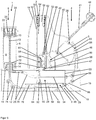
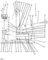
- FIGS. 1 to 8 show various views of a mixing device according to the invention before and during operation.
- the mixing device essentially consists of five parts, namely a cartridge system 1, a liquid container 2, a manually operated pressure pump 3, an operating element 4 and an opening device 5.
- the central component of the cartridge system 1 is a cartridge 6 with a cylindrical interior, which is closed at its upper side by a two-part discharge piston 8, which is arranged to be movable in the cylindrical interior of the cartridge 6 in the longitudinal direction.
- the cartridge 6 thus has a cylindrical interior with a circular base.
- the cartridge 6 contains a cement powder 9 as a starting component for a bone cement.
- a mixing device 10 is further arranged with two or more mixing blades 10, wherein the mixing device 10 is rotatable and in Is longitudinally displaceably mounted in the interior of the cartridge 6 and which is fixed to a mixing shaft 12 or to a cable 12 which is rotatably and longitudinally displaceably guided through a passage in the bottom of the cartridge 6 in the interior of the cartridge 6.
- the implementation is designed to pressure-tight.
- the mixing shaft 12 can also be designed as a flexible rod 12.
- the cartridge system 1 is connected to the liquid container 2 and the pressure pump 3 via a foot part 18 and a housing 19.
- the liquid container 2, the pressure pump 3, a part of the operating element 4 and the opening device 5 are enclosed by the housing 19, wherein a part of the operating element 4 protrudes from the housing 19, while the cartridge system 1 is screwed onto the housing 19.
- the cartridge 6 terminates at its bottom in a socket with an internal thread 14 which is screwed onto an external thread 16 on a neck of the housing 19.
- the foot part 18 forms the base 18 of the compact mixing device. The cartridge 6 is thereby detachable from the housing 19 and thus the rest of the mixing device.
- a static mixer may be provided which causes additional mixing of the bone cement dough 96.
- the two-part discharge piston 8 has a sealing piston 20 and a sterilization piston 22.
- the sterilization piston 22 has a membrane or pore disk 24, which is permeable to a sterilizing gas but is not permeable to the cement powder 9.
- the sterilization piston 22 is inserted after filling the cement powder 9 in the cartridge 6 and closes the interior of the cartridge 6 to the outside. Subsequently, the contents of the cartridge 6 can be sterilized by the gas-permeable membrane or pore disk 24 with ethylene dioxide.
- the sealing piston 20 can be pressed into the sterilizing piston 22 and connected to this gas and pressure-tight.
- the attached piston parts 20, 22 then form together the discharge piston 8, with which the contents of the cartridge 6 can be pressed out through the opening in the socket with the internal thread 14.
- the sterilization piston 22 is on the opposite side with the opening in the neck with the internal thread 14 (in the FIGS. 3, 4 and 6 to 8 locked above), wherein the lock is releasable. By locking prevents the sterilization piston 22 during the sterilization of the interior of the cartridge 6 and the cement powder 9 moves unintentionally.
- the mixing vanes 10 can be rotated in the interior of the cartridge 6, that is to say in the interior of the cartridge 6, and moved in the longitudinal direction of the cartridge 6.
- a passage is provided, through which the interior of the cartridge 6 can be evacuated.
- a vacuum pump (not shown) may be connected to the bushing via a vacuum line (not shown) as part of the mixing device.
- this vacuum pump is operated and driven by the operating element 4.
- the sealing piston 20 otherwise closes pressure-tight with the cartridge 6.
- the pressure pump 3 has a stable hollow cylinder 29 which limits the cylindrical pump chamber 28.
- the hollow cylinder 29 is pressure-tightly separated into two parts via a piston 30.
- the piston 30 has a circumferential seal 32, which terminates with the inner wall of the hollow cylinder 29.
- the piston 30 is connected to a cable 34 or a flexible rod 34 made of a sturdy elastic plastic or of a metal such as steel, which leads through a passage in a rear closure 33.
- the closure 33, the piston 30 and the hollow cylinder 29 define the pumping space 28.
- the pressure pump 3 On the front side, the pressure pump 3 is closed by a front-side closure in which openings are located so that air can flow in.
- the front-side closure can also be omitted and the pressure pump 3 can be made completely open on this page.
- the connecting line 26 is guided up to the junction 27 in the pressure pump 3, so that the implementation in the interior of the cartridge. 6 via the connecting line 26 liquid-tight with the pressure pump 3 is more precisely connected to the pump chamber 28 of the pressure pump 3.
- the cable 34 is connected to a latching means 36 which can latch with a counter-latching means 38 (see FIGS. 7 and 8th ).
- the counter-latching means 38 is part of the operating element 4, which is constructed as a lever 40 rotatable or pivotable about an axis 40.
- the lever 4 comprises two lever arms 41, 42 which extend from the axis 40 in different directions.
- the actual operating part of the lever 4 forms the first lever arm 41, which ends in a handle 44 which is manually operable from the outside.
- the first lever arm 41 thus projects out of the housing 19 and the handle 44 is arranged outside the housing 19 and can be operated manually by the user of the mixing device. In this case, a considerable force can be transmitted to the interior of the mixing device via the first lever arm 41, which is sufficient for driving the opening device 5, the pressure pump 3 and the mixing device 10 and applied according to the invention.
- the second lever arm 42 presses when pivoting the lever 4 and when pressing down the lever 4 on the opening means 5 and drives them.
- the opening device 5 is constructed with a lever 46 which is mounted rotatably or pivotably about an axis 47. At the opposite end of the axis 47 of the lever 46, an insert with an edge 48 is provided, which bears against the receptacle 2 and the liquid container 2.
- the liquid container 2 or the receptacle 2 comprises an inner elastic insert 50, which may for example consist of a rubber, and a rigid hollow cylinder 52 made of a plastic such as plastic.
- a glass ampoule 54 containing a monomer liquid is inserted in the receptacle 2 and the liquid container 2.
- the monomer liquid forms with the cement powder 9 from the cartridge 6 a bone cement dough 96 when they are mixed together.
- the inner walls of the elastic insert 50 abut the glass ampoule 54.
- the glass ampoule 54 has an ampoule head 56 and an ampoule bottom 58 opposite the ampoule head 56.
- the glass ampoule 54 sits with the ampoule bottom 58 on a support 60, which is formed as a shoulder 60 of the elastic insert 50.
- a hollow cylinder 62 presses from a gas-permeable foam, which on the inside of Housing 19 is fixed, the glass ampoule 54 on the support 60.
- the hollow cylinder 52 and the housing 19 openings are provided, can flow through the air or gas from the environment of the receptacle 2 and the mixing device in the receptacle 2.
- the openings between the hollow cylinder 52 and the housing 19 are designed such that they are arranged in the cylinder jacket wall of the hollow cylinder 52 adjacent to the upper base surface of the hollow cylinder 52.
- the hollow cylinder 52 is thus only partially in contact with the housing 19. In between, air can flow into the interior of the receptacle 2.
- the hollow cylinder 52 has a recess within which the edge 48 rests against the elastic insert 50, so that the ampoule bottom 58 can be broken off with the opening device 5 and thus the glass ampoule 54 can be opened.
- the ampoule head 56 of the glass ampoule 54 is usually broken off to open the glass ampoule 54.
- the glass ampoule 54 is made thin at the neck, this will cause the monomer liquid from the glass ampoule 54 to drain only slowly and therefore the user must wait until he can perform the next steps to operate the mixing device. This is not suitable in the largely automated method, which is driven by operating the lever 4 or the operating element 4, since it could not be ensured that the monomer liquid from the glass ampoule 54 is already available when the pressure pump 3 is operated via the operating element 4 is driven.
- the glass ampoule 54 is inserted in the insert 50 of the deformable material.
- the insert 50 forms together with the hollow cylinder 52, the essential parts of the receptacle 2 for the glass ampoule 54.
- the glass ampoule 54 can be inserted due to the paragraph 60 only to the ampoule bottom 58 in the insert 50 of the liquid container 2.
- the liquid container 2 has a lateral opening in which the insert 50 forms a deformable side wall.
- the glass ampoule 54 can be opened or broken by a pressure acting through the deformable side wall 50 on the glass ampoule 54 just above the ampoule bottom 58.
- the monomer liquid from the opened glass ampoule 54 can flow out in the full cross section, so that the monomer liquid is quickly available to the full extent for further processing within the mixing device.
- the lever 42 is used, which is operable via the lever 4 and which can be rotated about the axis 40.
- the lever 4 is pivotally mounted or rotatable about the axis 40 against the housing 19.
- the axle 40 divides the lever 4 into a long lever arm 41 to which the handle 44 is attached and a short lever arm 42 which is disposed within the housing 19. At the beginning of the long lever arm 41 can only be moved away from the liquid container 2 and not on this, since the long lever arm 41 abuts the top of the opening of the housing 19 and thus prevents further movement in this direction.
- the short lever arm 42 of the lever 4 rests on its side facing the liquid container 2 on the lever 46 of the opening device 5, which is connected via a hinge 47 or the axis 47 rotatable about the axis 47 with the foot part 18 and the housing 19 of the mixing device ,
- This lever 46 of the opening device 5 is disposed within the housing 19.
- the free lever end of the lever 46 in the housing 19 can be moved with the short lever arm 42.
- the edge 48 is fixed, which bears against the deformable side wall 50.
- the axis 47 of the lever 46 is arranged so that the free end of the lever and thus the edge 48 moves in the direction of the deformable side wall 50 and in the direction of the foot part 18.
- a sieve 64 and / or a filter 64 is arranged, with which or with which glass fragments of the opened or broken glass ampoule 54 are retained.
- the distance between the shoulder 60 and the screen 64 and / or filter 64 is greater than the outer diameter of the glass ampule 54, so that the sloping ampoule bottom 58 is in this Space 66 can rotate and the outflow of monomer liquid from the opened glass ampoule 54 is not hindered (see FIGS. 6 to 8 ).
- a funnel 68 is arranged, which opens into the pump chamber 28, when the piston 30 abuts against the front-side closure, ie, is arranged opposite the closure 33.
- the front of the cartridge 6 (in the FIGS. 1 to 4 and 6 to 8 Below) is liquid-tightly connected by the foot part 18 and the housing 19 via the connecting line 26 with the gap 66 and the funnel 68 of the liquid container 2.
- the cartridge 6 is attached to the housing 19 vertically detachably.
- the connecting line 26 opens into the nozzle with the external thread 16 through a powder-impermeable but permeable for the monomer liquid filter 72 into the interior of the cartridge 6.
- an annular channel 73 is formed (only in the Figures 3 and 8th but also in the FIGS. 4 . 6 and 7 to see), which is open to the filter 72, so that the likewise annular filter 72 covers the annular channel 73.
- the annular channel 73, in which the connecting line 26 opens and which actually belongs to the connecting line 26, and the annular filter 72 surround the passage in which the mixing shaft 12 and the cable 12 is guided into the interior of the cartridge 6.
- seals (not shown) or at least scrapers (not shown) may be provided in the passage.
- seals (not shown) or at least scrapers (not shown) may be provided in the passage.
- the liquid container 2 is closed with the housing 19 upwards after the glass ampoule 54 has been inserted into the liquid container 2.
- the monomer liquid without problems from the glass ampoule 54 and the space 66 may leak or drain, in addition, in the liquid container 2 covering part of the housing 19 more Passages (not shown) may be provided, can flow from the outside into the liquid container 2 through the air.
- the monomer liquid flows in the pumping space 28 and can be pressed with the piston 30 through the connecting line 26 into the interior of the cartridge 6.
- the pressure required for this purpose is generated with the pressure pump 3 by the piston 30 is pulled with the cable 34 or the rod 34 to the shutter 33, whereby the pump chamber 28 of the pressure pump 3 decreases.
- the monomer liquid can then be mixed with the cement powder 9 by means of the mixing device 10 to produce the bone cement 96 and a bone cement dough 96, respectively.
- the mixture can be carried out under vacuum or under vacuum by connecting to the vacuum connection to the sealing piston 20 a vacuum pump (not shown) or another vacuum source.
- the mixing device 10 is used for mixing the contents of the interior of the cartridge 6.
- the pulleys 74 can be constructed with spring-mounted tube or deflection sleeves. The springs serve only to fix the pulleys 74 and deflecting sleeves.
- the cable 12 or the mixing shaft 12 is rigidly connected to the cylinder 76.
- the cylinder 76 has a steep external thread 78 on the outside.
- the cylinder 76 is arranged in a sleeve 80 with an external thread 78 matching internal thread 82.
- the mixing device 10 is thus moved over the cable 12 or the mixing shaft 12 in the longitudinal direction of the interior of the cartridge 6 and simultaneously rotated about the mixing shaft 12 due to the threads 78, 82 and so that the contents of the interior mixes.
- one or more projections or one or more cams 78 can also be provided, which run in the internal thread 82 and thus rotate the cylinder 76 in the sleeve 80.
- the cylinder 76 is via a ball joint or a ball joint head 84 with a rigid cable 86 or a flexible rod 86, which is analogous to the cable 34th or the flexible rod 34 is constructed for the pressure pump 3, connected.
- the ball joint head 84 can thus move within a receptacle for the ball joint head 84 of the cylinder 76 and rotate therein. This makes it possible for a movement of the cable 86 at the same time a rotation of the cylinder 76 in the sleeve 80 is enforced.
- the cable 86, which is connected to the cylinder 76 and the cable 34, which is connected to the piston 30 of the pressure pump 3, are connected to each other, wherein both are positioned via pins 88 and pulleys 88.
- the pulleys 88 are constructed analogous to the pulleys 74.
- the connection of the cable 34 to the piston 30 can be constructed with a ball joint.
- the two cables 34, 86 or flexible rods 34, 86 close to a cable 90 or a flexible rod 90 together, which is guided upwards to the lever 4 and the control element 4, wherein the cable 90 or the flexible rod 90 there in the Locking means 36 ends.
- the cable 90 is constructed analogously to the cable 34 for the pressure pump 3, or the flexible rod 90 analogous to the flexible rod 34 for the pressure pump 3.
- the forked connected cables 34, 86, 90 or the forked rod 34, 86, 90 can from be made of plastic by injection molding, or the common forked cable 34, 86, 90 or the forked rod 34, 86, 90 may be made of a plastic by injection molding.
- the locking means 36 at the end of the cable 90 is thereby stored and biased so that it engages in the counter-latching means 38 and locked with this, when the lever 4 is rotated or pivoted far enough, or if the counter-locking means 38 to the height of the locking means 36th is pivoted.
- the maximum stroke which is determined by a curve 34 formed as an involute 83 on the lever 4 by the cable 90 or the flexible rod 90 is pulled onto the involute 83 after detenting sufficient to ensure that the interior of the cartridge 6 in full length can be traversed by the mixing device 10.
- a curve 34 formed as an involute 83 on the lever 4 by the cable 90 or the flexible rod 90 is pulled onto the involute 83 after detenting sufficient to ensure that the interior of the cartridge 6 in full length can be traversed by the mixing device 10.
- the counter-locking means 38 is arranged on the respect to the pulling direction of the cable 90, 34, 86 or the flexible rod 90, 34, 86 opposite end of the involute 83, so that the cable 90 or the flexible rod 90 over a wide range of involute 83 wound can be.
- the cables 34, 86 or each of the flexible rods 34, 86 have their own locking means, which engages in the counter-locking means 38 or the two different counter-locking means at the end of the involute 83 and the lever 4 and snaps with this or this.
- the cable 12 may be connected directly to the cable 86, or the two cables 12, 86 may be designed as a common continuous cable, or the flexible rod 12 may be made in one piece with the flexible rod 86.
- the cylinder 76, the sleeve 80 and the threads 78, 82 are then superfluous and not available. This then causes the mixing device 10 is no longer rotated by the mixing shaft 12 in the interior of the cartridge 6. A mixing of the interior of the cartridge 6 is then achieved only by the up and down movement of the mixing device 10 in the longitudinal direction.
- FIG. 5 shows a schematic cross-sectional view of the mixing device according to the FIGS. 1 to 4 and 6 to 8 with a sectional plane perpendicular to the section of the Figures 3 and 4 as well as 6 to 8.
- the mixing device is characterized by the applicability of the following exemplary method according to the invention.
- the monomer liquid is provided in the liquid container 2 by breaking the glass ampoule 54 with the opening means 5 as described above.
- the lever 4 which is originally in a vertical position (see Figure 1 to 4 ) is pressed down (see FIG. 6 ). While the monomer liquid leaks out and fills the pumping space 28 of the pressure pump 3, the lever 40 is further rotated or pivoted until the counter-locking means 38 is rotated to the height of the latching means 36 and both snap together (see FIG. 7 ).
- the pressure pump 3 is used by pulling the piston 30 with the operating element 4 via the cable 34, 90 or via the flexible rod 34, 90 away from the front-side closure in the direction of the closure 33.
- the pumping space 28 is reduced in the interior of the pressure pump 3. The reduction of the pumping space 28 forces the monomer liquid out of the pumping space 28 and the connecting line 26 into the interior of the cartridge 6.
- the piston 30 is up to the end of the hollow cylinder 29 (in the FIGS. 3 to 4 and 6 to 8 right). This arrangement is in FIG. 8 shown.
- the decrease in volume of the pump chamber 28 may preferably be sufficient to completely push the monomer liquid from the liquid container 2 into the interior of the cartridge 6, so that a stroke of the piston 30 is sufficient to transfer the monomer liquid into the interior of the cartridge 6.
- the expanded pump space 28 may preferably be greater than or equal to the volume of the monomer liquid in the glass ampoule 54.
- the monomer liquid but also with multiple strokes of the piston 30 by repeated operation of the lever 4 (swinging back and forth of the lever 4) are pressed into the interior of the cartridge 6.
- the piston 30 has something unlike in the FIGS. 3 to 8 be shown constructed.
- the piston 30 should do this except in the starting position (see FIGS. 3 to 7 ) Always close the connection to the hopper 68 so be extended at least in this area. This prevents the monomer liquid from simply flowing into the free area next to the piston 30 into the pressure pump 3.
- the cartridge system 1 When the starting components in the interior of the cartridge 6 have been mixed with the mixing blades 10, the cartridge system 1 is unscrewed from the housing 19 or the external thread 16 of the housing 19 and the cable 12 or the mixing shaft 12 with the mixing device 10 is pulled out of the interior of the cartridge 6 , The mixing blades 10 fold upwards together.
- 12 material tapers are provided as predetermined bending points at the compound of the mixing blades 10 to the mixing shaft.
- a dispensing tube (not shown) with a suitable external thread is screwed into the internal thread 14, through which the mixed bone cement 96 can be applied.
- the delivery piston 8 or discharge piston 8 composed of the sterilization piston 22 and the sealing piston 20 is unlatched and can be driven into the interior of the cartridge 6 with an application device (not shown). Characterized the contents of the cartridge 6, so the mixed bone cement dough 96 is pressed out of the opposite opening and through the screwed-discharge tube.
- the components of the mixing device can be made by injection molding of plastic except for the glass ampoule 54, the filter 64, 72 and the output components of the bone cement.
- the connecting line 26 and the cables 34, 86, 90 or the forked bar 34, 86, 90 are arranged in the housing 19 made of plastic, which is firmly connected to the foot part 18, wherein the foot part 18 has a flat bottom, so that the mixing device can be placed on a flat surface.
- a film bag containing the monomer liquid can be used as a container for the monomer liquid in a modified recording.
- the film bag may be, for example, a plastic bag coated with aluminum, which is chemically sufficiently resistant to the monomer liquid.
- receptacle 2 may then be provided a mandrel or, better, a blade which is to be pressed and moved with the opening device 5 against the film bag so that the film bag can be pierced or slit through the opening device 5 with the mandrel or the blade , So that then the monomer liquid leaking from the foil bag and is available in the receptacle 2.
- the container for the monomer liquid can also be firmly integrated in the receptacle 2 and therefore in the mixing device and can be opened with the opening device 5 to the filter 64 and / or screen 64 or to the hopper 68.
- the variant with glass ampoule 54 as container for the monomer liquid is preferred according to the invention, since the filled with monomer liquid glass ampoules 54 are commercially inexpensive to obtain and also glass ampoules 54 for long-term storage of monomer liquid are particularly well suited. It is particularly preferred that the glass ampoule 54 is already included in the receptacle 2 of the mixing device.
- the two starting components of the bone cement can be stored and mixed at any later time.
- the mixing device does not have to be connected to any external supply (electricity, water or pressurized gas). It is not an internal energy storage, such as a battery, compressed gas cartridge or tensioned spring, to power the mixing device or the pressure pump 3, the mixing device 10 and the opening device 5 necessary.
- the energy necessary for transferring the monomer liquid is also applied manually, as well as the force necessary to open the glass ampoule 54 and to move the mixing device 10.
Abstract
Die Erfindung betrifft eine Mischvorrichtung zum Mischen von PMMA-Knochenzement aus einer Monomerflüssigkeit und einem Zementpulver (9), die Mischvorrichtung aufweisend zumindest eine Kartusche (6) umfassend einen evakuierbaren Innenraum zum Mischen des Knochenzements (96), eine Mischeinrichtung (10) zum Durchmischen des Inhalts des Innenraums der zumindest einen Kartusche (6), die beweglich im Innenraum angeordnet ist, eine Aufnahme (2) zur Aufnahme eines die Monomerflüssigkeit enthaltenden separaten Behälters (54) oder aufweisend einen integrierten Behälter enthaltend die Monomerflüssigkeit, eine Öffnungseinrichtung (5), die im Bereich der Aufnahme (2) gegen die Aufnahme (2) beweglich angeordnet ist, so dass durch eine Bewegung der Öffnungseinrichtung (5) ein in der Aufnahme (2) angeordneter separater Behälter (54) mit der Öffnungseinrichtung (5) zu öffnen ist, oder die Öffnungseinrichtung (5) im Bereich des integrierten Behälters gegen den integrierten Behälter beweglich angeordnet ist, so dass durch eine Bewegung der Öffnungseinrichtung (5) der integrierte Behälter mit der Öffnungseinrichtung (5) zu öffnen ist, eine Druckpumpe (3), in der ein beweglicher Kolben (30) zum Fördern einer Flüssigkeit angeordnet ist und der einen Pumpraum (28) der Druckpumpe (3) begrenzt, und eine Verbindungsleitung (26), die den Innenraum der zumindest einen Kartusche (6) mit dem Pumpraum (28) der Druckpumpe (3) verbindet, wobei die Mischvorrichtung ein von außen bedienbares Bedienelement (4) aufweist, wobei mit dem Bedienelement (4) der Kolben (30) in der Druckpumpe (3) manuell bewegbar ist, und wobei mit demselben Bedienelement (4) die Öffnungseinrichtung (5) gegen die Aufnahme (2) oder gegen den integrierten Behälter zu bewegen ist, und mit demselben Bedienelement (4) die Mischeinrichtung (10) im Innenraum der Kartusche (6) zum Durchmischen des Inhalts des Innenraums der Kartusche (6) bewegbar ist. Die Erfindung betrifft auch ein Verfahren zum Mischen von PMMA-Knochenzement.The invention relates to a mixing device for mixing PMMA bone cement from a monomer liquid and a cement powder (9), the mixing device comprising at least one cartridge (6) comprising an evacuatable interior for mixing the bone cement (96), a mixing device (10) for mixing the Contents of the interior of the at least one cartridge (6) which is movably arranged in the interior, a receptacle (2) for receiving a monomer liquid containing separate container (54) or comprising an integrated container containing the monomer liquid, an opening device (5) is movably arranged in the region of the receptacle (2) against the receptacle (2), so that a separate container (54) arranged in the receptacle (2) with the opening device (5) can be opened by a movement of the opening device (5), or the opening device (5) in the region of the integrated container against the integrated container beweglic h is arranged so that by a movement of the opening means (5) of the integrated container with the opening means (5) is open, a pressure pump (3) in which a movable piston (30) for conveying a liquid is arranged and the one Pumping space (28) of the pressure pump (3) limited, and a connecting line (26) which connects the interior of the at least one cartridge (6) with the pump space (28) of the pressure pump (3), wherein the mixing device is an externally operable control element (26). 4), wherein with the operating element (4) of the piston (30) in the pressure pump (3) is manually movable, and wherein the same operating element (4) the opening means (5) against the receptacle (2) or against the integrated container is to move, and with the same control element (4), the mixing device (10) in the interior of the cartridge (6) for mixing the contents of the interior of the cartridge (6) is movable. The invention also relates to a method for mixing PMMA bone cement.
Description
Die Erfindung betrifft eine Mischvorrichtung zum Mischen von Polymethylmethacrylat-Knochenzement (PMMA-Knochenzement) aus zwei Ausgangskomponenten, insbesondere zum Mischen eines medizinischen Knochenzements, und zur Lagerung der Ausgangskomponenten. Die Erfindung betrifft ferner ein Verfahren zum Mischen von Polymethylmethacrylat-Knochenzement.The invention relates to a mixing device for mixing polymethyl methacrylate bone cement (PMMA bone cement) from two starting components, in particular for mixing a medical bone cement, and for storing the starting components. The invention further relates to a method for mixing polymethyl methacrylate bone cement.
Gegenstand der Erfindung ist somit eine Mischvorrichtung für die Lagerung, Vermischung und gegebenenfalls auch den Austrag von Polymethylmethacrylat-Knochenzement. Weiterhin betrifft die Erfindung ein Verfahren zum Transfer von Monomerflüssigkeit in die Mischvorrichtung und ein Verfahren zum Vermischen der Komponenten von Polymethylmethacrlyat-Knochenzement.The invention thus relates to a mixing device for the storage, mixing and optionally also the discharge of polymethyl methacrylate bone cement. Furthermore, the invention relates to a method for transferring monomer liquid into the mixing device and a method for mixing the components of polymethyl methacrylate bone cement.
Polymethylmethacrylat-Knochenzemente (PMMA-Knochenzemente) gehen auf die grundlegenden Arbeiten von Sir Charnley zurück. PMMA-Knochenzemente bestehen aus einer flüssigen Monomerkomponente und einer Pulverkomponente. Die Monomerkomponente enthält im Allgemeinen das Monomer Methylmethacrylat und einen darin gelösten Aktivator (N,N-Dimethyl-p-toluidin). Die Pulverkomponente, auch als Knochenzementpulver bezeichnet, weist ein oder mehrere Polymere auf, die auf Basis von Methylmethacrylat und Comonomeren, wie Styren, Methylacrylat oder ähnlichen Monomeren durch Polymerisation, vorzugsweise Suspensionspolymerisation, hergestellt sind. Zudem weist das Knochenzementpulver einen Röntgenopaker und den Initiator Dibenzoylperoxid auf. Beim Vermischen der Pulverkomponente mit der Monomerkomponente entsteht durch Quellung der Polymere der Pulverkomponente im Methylmethacrylat ein plastisch verformbarer Teig, der eigentliche Knochenzement. Beim Vermischen der Pulverkomponente mit der Monomerkomponente reagiert der Aktivator N,N-Dimethyl-p-toluidin mit Dibenzoylperoxid unter Bildung von Radikalen. Die gebildeten Radikale initiieren die radikalische Polymerisation des Methylmethacrylats. Mit fortschreitender Polymerisation des Methylmethacrylats erhöht sich die Viskosität des Zementteigs, bis dieser erstarrt.Polymethyl methacrylate bone cements (PMMA bone cements) are based on the fundamental work of Sir Charnley. PMMA bone cements consist of a liquid monomer component and a powder component. The monomer component generally contains the monomer methyl methacrylate and an activator (N, N-dimethyl-p-toluidine) dissolved therein. The powder component, also referred to as bone cement powder, comprises one or more polymers prepared on the basis of methyl methacrylate and comonomers, such as styrene, methyl acrylate or similar monomers by polymerization, preferably suspension polymerization. In addition, the bone cement powder has an X-ray opaque and the initiator dibenzoyl peroxide. When the powder component is mixed with the monomer component, swelling of the polymers of the powder component in methyl methacrylate produces a plastically deformable dough, the actual bone cement. Upon mixing the powder component with the monomer component, the activator reacts N, N-dimethyl-p-toluidine with dibenzoyl peroxide to form radicals. The radicals formed initiate the radical polymerization of the methyl methacrylate. As the polymerization of methyl methacrylate progresses, the viscosity of the cement dough increases until it solidifies.
Das am häufigsten in Polymethylmethacrylat-Knochenzementen verwendete Monomer ist Methylmethacrylat. Redoxinitiatorsysteme bestehen üblicherweise aus Peroxiden, Beschleunigern sowie gegebenenfalls geeigneten Reduktionsmitteln. Eine Radikalbildung erfolgt nur dann, wenn alle Bestandteile der Redoxinitiatorsysteme zusammenwirken. Deshalb werden die Bestandteile des Redoxinitiatorsystems in den separaten Ausgangskomponenten so angeordnet, dass diese keine radikalische Polymerisation auslösen können. Die Ausgangskomponenten sind bei geeigneter Zusammensetzung lagerstabil. Erst bei Vermischung der beiden Ausgangskomponenten zu einem Zementteig reagieren die zuvor getrennt in den beiden Pasten, Flüssigkeiten oder Pulvern gelagerten Bestandteile des Redoxinitiatorsystems, wobei Radikale gebildet werden, welche die radikalische Polymerisation des wenigstens einen Monomers auslösen. Die radikalische Polymerisation führt dann unter Verbrauch des Monomers zu Bildung von Polymeren, wobei der Zementteig aushärtet.The monomer most commonly used in polymethyl methacrylate bone cements is methyl methacrylate. Redox initiator systems usually consist of peroxides, accelerators and optionally suitable reducing agents. A radical formation takes place only when all components of the redox initiator systems interact. Therefore, the components of the redox initiator system are placed in the separate starting components so that they can not initiate radical polymerization. The starting components are storage stable with a suitable composition. It is only when the two starting components are mixed to form a cement dough that the components of the redox initiator system previously stored separately in the two pastes, liquids or powders react, forming radicals which trigger the radical polymerization of the at least one monomer. The radical polymerization then leads to the formation of polymers with consumption of the monomer, wherein the cement paste hardens.
PMMA-Knochenzemente können in geeigneten Mischbechern mit Hilfe von Spateln durch Vermischen des Zementpulvers mit der Monomerflüssigkeit vermischt werden. Nachteilig ist an dieser Vorgehensweise, dass Lufteinschlüsse im gebildeten Zementteig vorhanden sein können, die später eine mechanische Destabilisierung des Knochenzements verursachen können.PMMA bone cements can be mixed in suitable mixing beakers by means of spatulas by mixing the cement powder with the monomer liquid. The disadvantage of this approach is that air pockets may be present in the formed cement paste, which may later cause a mechanical destabilization of the bone cement.
Zur Vermeidung von Lufteinschlüssen im Knochenzementteig wurden eine Vielzahl von Vakuum-Zementiersystemen offen gelegt, von denen exemplarisch folgende genannt sind:
Eine Weiterentwicklung in der Zementiertechnik stellen Zementiersysteme dar, in denen sowohl das Zementpulver als auch die Monomerflüssigkeit bereits in separaten Kompartimenten der Mischsysteme verpackt sind und die erst unmittelbar vor der Zementapplikation im Zementiersystem miteinander vermischt werden. Solche geschlossenen Full-Prepacked-Mischsysteme wurden mit der
In der
Nachteilig an diesem System ist, dass Zementpulver, die schnell mit der Monomerflüssigkeit anquellen, mit dieser Vorrichtung nicht angemischt werden können, weil die schnell anquellenden Zementpulverpartikel nach einem Eindringen der Monomerflüssigkeit in das Zementpulver von ungefähr 1 bis 2 cm eine gelartige Barriere bilden und die Migration der Monomerflüssigkeit durch das gesamte Zementpulver behindern. Weiterhin kann bei Vakuumeinwirkung nicht ausgeschlossen werden, dass nach vollständiger Durchdringung des Zementpulvers durch die Monomerflüssigkeit die Monomerflüssigkeit über den Vakuumanschluss abgesaugt wird. Dann steht nicht genügend Monomerflüssigkeit für die Aushärtung durch radikalische Polymerisation zur Verfügung beziehungsweise das Mischungsverhältnis wird ungewollt verändert und damit auch die Konsistenz des Knochenzements. Weiterhin ist es problematisch, dass die zwischen den Zementpulverpartikeln eingeschlossen Luft durch die Monomerflüssigkeit von oben nach unten verdrängt werden soll, weil die gegenüber der Monomerflüssigkeit spezifisch leichtere Luft auf Grund der Schwerkraft das Bestreben hat, im Zementpulver nach oben zu wandern und nicht nach unten in Richtung Vakuumanschluss zu migrieren.A disadvantage of this system is that cement powders swelling rapidly with the monomer liquid can not be mixed with this device because the rapidly swelling cement powder particles form a gelatinous barrier after penetration of the monomer liquid into the cement powder of about 1 to 2 cm and the migration hinder the monomer liquid through the entire cement powder. Furthermore, it can not be ruled out under vacuum action that after complete penetration of the cement powder by the monomer liquid, the monomer liquid is sucked off via the vacuum connection. Then there is not enough monomer liquid for curing by free radical polymerization available or the mixing ratio is changed unintentionally and thus the consistency of the Bone cement. Furthermore, it is problematic that the trapped between the cement powder particles air is to be displaced by the monomer liquid from top to bottom, because the lighter than the monomer liquid air due to gravity has a tendency to migrate in the cement powder upwards and not down in To migrate towards vacuum connection.
Bei der Verwendung von Mischvorrichtungen zur Zementierung müssen externe Vakuumpumpen beigestellt werden. Diese Vakuumpumpen sind kostenintensiv und müssen nach der Anwendung gereinigt werden. Weiterhin sind Vakuumschläuche zur Verbindung der Vakuumpumpen mit den Mischvorrichtungen notwendig. Diese Vakuumschläuche müssen den Mischvorrichtungen beigelegt sein. Vor dem Mischen mit einer Mischvorrichtung muss daher zuerst die Vakuumpumpe im Operations-Saal (OP-Saal) aufgebaut und an eine Energiequelle, wie beispielsweise Druckluft, oder an eine elektrische Spannungsquelle angeschlossen werden. Danach wird die Vakuumpumpe mit einem Vakuumschlauch mit der Mischvorrichtung verbunden. Diese Montageschritte kosten wertvolle OP-Zeit und sind potentiell fehlerbehaftet. Die Vakuumpumpe und die Verbindungsleitungen zur Mischvorrichtung und zu externen Energiequellen und Versorgungsleitungen benötigen Platz und stellen potentielle Stolperfallen und Hindernisse dar, die den gelegentlich hektischen Ablauf während einer Operation stören können.When using mixing devices for cementing, external vacuum pumps must be provided. These vacuum pumps are expensive and must be cleaned after use. Furthermore, vacuum hoses are necessary for connecting the vacuum pumps with the mixing devices. These vacuum hoses must be enclosed with the mixing devices. Therefore, before mixing with a mixing device, the vacuum pump must first be set up in the operating room (operating room) and connected to an energy source, such as compressed air, or to an electrical power source. Thereafter, the vacuum pump is connected to the mixing device with a vacuum hose. These assembly steps cost valuable operating time and are potentially flawed. The vacuum pump and the connection lines to the mixing device and to external power sources and supply lines require space and represent potential tripping hazards and obstacles that can interfere with the occasionally hectic flow during an operation.
Ein weiteres interessantes Konzept wird mit der
Die Mischvorrichtung soll maximal vereinfacht sein und in der Lage sein, einen Transfer von Monomerflüssigkeit aus einem Monomerbehälter in eine mit Zementpulver gefüllte Kartusche zu ermöglichen. Es soll dann ferner ein Verfahren bereitgestellt werden, das einen Monomertransfer und ein Mischen der Komponenten in Full-Prepacked-Mischvorrichtungen ermöglicht. Weiterhin soll die zu entwickelnde Mischvorrichtung hauptsächlich aus kostengünstigem Kunststoff gefertigt werden können.The mixing device is intended to be maximally simplified and to be able to enable a transfer of monomer liquid from a monomer container into a cartridge filled with cement powder. It is then further to provide a method that allows for monomer transfer and mixing of the components in full-prepacked mixing devices. Furthermore, the mixing device to be developed should mainly be made of inexpensive plastic.
Die Erfindung hat ferner die Aufgabe, eine einfache geschlossene Prepack-Mischvorrichtung zu entwickeln, bei der Polymethylmethacrylat-Knochenzementpulver und Monomerflüssigkeit in separaten Kompartimenten gelagert und anschließend vermischt werden können. Unmittelbar vor der Vermischung der Komponenten soll die Monomerflüssigkeit ohne Nutzung von externen Vakuumquellen, externen elektrischen Antrieben und externen Druckluftantieben in das Zementpulver transferiert werden. Mit der Prepack-Mischvorrichtung soll unabhängig von zusätzlichen externen Vorrichtungen rein durch manuelle Betätigung Polymethylmethacrylat-Knochenzement erzeugt werden können. Dabei soll die manuelle Betätigung so weit wie möglich vereinfacht werden. Vorzugsweise soll das Öffnen der Monomerampulle, beziehungsweise der Monomerampullen, der Monomertransfer und die Vermischung der Zementkomponenten nur durch möglichst eine einfache Bewegung eines Bedienelements bewirkt werden, die besonders bevorzugt nur wenige Male, beispielsweise 3 bis 5 mal, wiederholt werden muss. Dadurch soll die Benutzung der Mischvorrichtung für den Anwender maximal vereinfacht werden, so dass kostenintensive Schulungen eingeschränkt beziehungsweise eingespart werden können. Weiterhin soll durch eine maximal vereinfachte Bedienung der Mischvorrichtung mögliche Bedienungsfehler minimiert werden, wodurch die Patientensicherheit erhöht wird.Another object of the invention is to develop a simple closed-pack pre-pack mixer in which polymethyl methacrylate bone cement powders and monomer liquid can be stored in separate compartments and subsequently mixed. Immediately before the Mixing of the components, the monomer liquid is to be transferred without the use of external vacuum sources, external electrical drives and external Druckluftantieben in the cement powder. With the pre-pack mixing device, polymethyl methacrylate bone cement should be able to be produced purely by manual actuation, independent of additional external devices. The manual operation should be simplified as much as possible. Preferably, the opening of the monomer ampoule, or of the monomer ampoules, the monomer transfer and the mixing of the cement components should only be effected by a simple movement of a control element which is particularly preferred only a few times, for example 3 to 5 times repeated. As a result, the use of the mixing device for the user should be maximally simplified, so that cost-intensive training can be reduced or saved. Furthermore, should be minimized by a maximum simplified operation of the mixing device possible operating errors, whereby the patient safety is increased.
Vom medizinischen Anwender soll das Polymethylmethacrylat-Knochenzementpulver mit der Monomerflüssigkeit innerhalb der Mischvorrichtung zusammengeführt und vermischt werden können, ohne dass beide Zementkomponenten mit dem medizinischen Anwender in Berührung kommen. Ein Kontakt des medizinischen Anwenders mit dem Polymethylmethacrylat-Knochenzementpulver und mit der Monomerflüssigkeit muss ausgeschlossen sein. Bei der zu entwickelnden Mischvorrichtung handelt es sich um eine Full-Prepack Mischvorrichtung. Die Mischvorrichtung soll so beschaffen sein, dass ein Transfer der Monomerflüssigkeit in das Polymethylmethacrylat-Knochenzementpulver ohne die Verwendung von externen Vakuumpumpen erfolgt. Des Weiteren soll die Mischvorrichtung ohne externe Energiequellen, wie Druckluft, Vakuum oder elektrischer Strom, auch unter einfachsten äußeren Bedingungen funktionsfähig und zuverlässig die Herstellung von Knochenzementteig gewährleisten. Besonders bevorzugt soll die Mischvorrichtung möglichst weitgehend auch ohne interne Energiespeicher, wie beispielsweise Batterien oder auch mechanische Energiespeicher auskommen Die Mischvorrichtung soll ohne zusätzliche technische Ausrüstung autonom verwendungsfähig sein.The medical practitioner should be able to combine and mix the polymethyl methacrylate bone cement powder with the monomer fluid within the mixing device without the two cement components coming into contact with the medical user. Contact of the medical practitioner with the polymethyl methacrylate bone cement powder and with the monomer liquid must be excluded. The mixing device to be developed is a full-prepack mixing device. The mixing device should be such that a transfer of the monomer liquid into the polymethylmethacrylate bone cement powder takes place without the use of external vacuum pumps. Furthermore, the mixing device without external energy sources, such as compressed air, vacuum or electric current, even under the simplest external conditions functional and reliable to ensure the production of bone cement dough. Particularly preferably, the mixing device should as far as possible even without internal energy storage, such as batteries or mechanical energy storage The mixing device should be autonomously usable without additional technical equipment.
Des Weiteren soll eine kostengünstig zu fertigende und zuverlässig funktionierende Mischvorrichtung zum Mischen eines medizinischen Zements und gegebenenfalls zur Lagerung der Ausgangskomponenten sowie ein Verfahren zum Mischen des Knochenzements gefunden werden, bei dem eine möglichst einfache manuelle Bedienung zum Mischen der Ausgangskomponenten angewendet werden kann.Furthermore, a mixing device for mixing a medical cement and optionally for storing the starting components, which is inexpensive to manufacture and reliably functioning, and a method for mixing the bone cement should be found, in which the simplest possible manual operation for mixing the starting components can be used.
Die Hauptkomponente des Polymethylmethacrylat-Knochenzements als Mischgut soll ein Pulver sein und die zweite Komponente soll in Form einer Flüssigkeit vorliegen. Die beiden Ausgangskomponenten des Knochenzements sollen bevorzugt in der Mischvorrichtung getrennt gelagert werden können und durch Anwendung der Vorrichtung sicher zusammengeführt werden können.The main component of the polymethyl methacrylate bone cement as a mix should be a powder and the second component should be in the form of a liquid. The two starting components of the bone cement should preferably be stored separately in the mixing device and can be safely combined by using the device.
Die Aufgaben der Erfindung werden gelöst durch eine Mischvorrichtung zum Mischen von Polymethylmethacrylat-Knochenzement aus einer Monomerflüssigkeit und einem Zementpulver, die Mischvorrichtung aufweisend zumindest eine Kartusche umfassend einen evakuierbaren Innenraum zum Mischen des Knochenzements,
eine Mischeinrichtung zum Durchmischen des Inhalts des Innenraums der zumindest einen Kartusche, die beweglich im Innenraum angeordnet ist,
eine Aufnahme zur Aufnahme eines die Monomerflüssigkeit enthaltenden separaten Behälters oder aufweisend einen integrierten Behälter enthaltend die Monomerflüssigkeit,
eine Öffnungseinrichtung, die im Bereich der Aufnahme gegen die Aufnahme beweglich angeordnet ist, so dass durch eine Bewegung der Öffnungseinrichtung ein in der Aufnahme angeordneter separater Behälter mit der Öffnungseinrichtung zu öffnen ist, oder die Öffnungseinrichtung im Bereich des integrierten Behälters gegen den integrierten Behälter beweglich angeordnet ist, so dass durch eine Bewegung der Öffnungseinrichtung der integrierte Behälter mit der Öffnungseinrichtung zu öffnen ist,
eine Druckpumpe, in der ein beweglicher Kolben zum Fördern einer Flüssigkeit angeordnet ist und der einen Pumpraum der Druckpumpe begrenzt, und
eine Verbindungsleitung, die den Innenraum der zumindest einen Kartusche mit dem Pumpraum der Druckpumpe verbindet, wobei
die Mischvorrichtung ein von außen bedienbares Bedienelement aufweist, wobei mit dem Bedienelement der Kolben in der Druckpumpe manuell bewegbar ist, und wobei mit demselben Bedienelement die Öffnungseinrichtung gegen die Aufnahme oder gegen den integrierten Behälter zu bewegen ist, und
mit demselben Bedienelement die Mischeinrichtung im Innenraum der Kartusche zum Durchmischen des Inhalts des Innenraums der Kartusche bewegbar ist.The objects of the invention are achieved by a mixing device for mixing polymethyl methacrylate bone cement from a monomer liquid and a cement powder, the mixing device having at least one cartridge comprising an evacuable interior for mixing the bone cement,
a mixing device for mixing the contents of the interior of the at least one cartridge, which is arranged movably in the interior,
a receptacle for receiving a monomeric liquid-containing separate container or comprising an integrated container containing the monomer liquid,
an opening device which is movably arranged in the region of the receptacle against the receptacle, so that a separate container arranged in the receptacle with the opening device can be opened by a movement of the opening device, or the opening device is movably arranged in the region of the integrated receptacle against the integrated receptacle is, so that is open by a movement of the opening means of the integrated container with the opening means,
a pressure pump in which a movable piston for conveying a liquid is arranged and which limits a pumping space of the pressure pump, and
a connecting line which connects the interior of the at least one cartridge with the pump chamber of the pressure pump, wherein
the mixing device has an externally operable control element, wherein the control element of the piston in the pressure pump is manually movable, and wherein the same operating element, the opening device against the recording or to move against the integrated container, and
with the same control element, the mixing device in the interior of the cartridge for mixing the contents of the interior of the cartridge is movable.
Bevorzugt ist die Mischvorrichtung auch zum Lagern der Ausgangskomponenten des Polymethylmethacrylat-Knochenzements geeignet. Besonders bevorzugt sind die Monomerflüssigkeit und/oder das Zementpulver in der Mischvorrichtung enthalten. Bei den Ausgangskomponenten des Polymethylmethacrylat-Knochenzements handelt es sich um das Zementpulver und die Monomerflüssigkeit, wobei die Monomerflüssigkeit bevorzugt in einer Glasampulle enthalten ist, die als separater Behälter in der Aufnahme angeordnet ist. Die Monomerflüssigkeit kann aber auch in einem Folienbeutel als separater Behälter enthalten sein oder sie kann in dem integrierten Behälter enthalten sein, der durch die Aufnahme beziehungsweise die Mischvorrichtung selbst gebildet wird.Preferably, the mixing device is also suitable for storing the starting components of the polymethyl methacrylate bone cement. Particularly preferably, the monomer liquid and / or the cement powder are contained in the mixing device. The starting components of the polymethyl methacrylate bone cement are the cement powder and the monomer liquid, the monomer liquid preferably being contained in a glass ampule which is arranged as a separate container in the receptacle. However, the monomer liquid can also be contained in a foil bag as a separate container or it can be contained in the integrated container, which is formed by the receptacle or the mixing device itself.
Der Begriff "Mischvorrichtung" soll dahingehend verstanden werden, dass die Ausgangskomponenten des Knochenzements, also die Monomerflüssigkeit und das Zementpulver, innerhalb der Vorrichtung gemischt werden können.The term "mixing device" is to be understood to mean that the starting components of the bone cement, ie the monomer liquid and the cement powder, can be mixed within the device.
Aufgrund der speziellen Anforderungen, wie die des geringen Volumens des Innenraums der Kartusche, sind aufwendigere Druckpumpen oder Transfersysteme nicht notwendig.Due to the special requirements, such as the small volume of the interior of the cartridge, more complex pressure pumps or transfer systems are not necessary.
Bevorzugt kann vorgesehen sein, dass die Druckpumpe in die Mischvorrichtung integriert ist.It can preferably be provided that the pressure pump is integrated in the mixing device.
Bevorzugt kann erfindungsgemäß auch vorgesehen sein, dass das Zementpulver in dem Innenraum der Kartusche enthalten ist. Das Zementpulver muss dann nicht in den Innenraum der Kartusche eingefüllt werden.Preferably, it can also be provided according to the invention that the cement powder is contained in the interior of the cartridge. The cement powder then does not have to be filled into the interior of the cartridge.
Durch die Kopplung der Öffnungseinrichtung mit dem Bedienelement ist der Behälter in der Aufnahme oder ist der integrierte Behälter durch manuelles Bedienen des Bedienelements mit der Öffnungseinrichtung zu öffnen.By coupling the opening device with the operating element, the container in the receptacle or the integrated container can be opened by manually operating the operating element with the opening device.
Die Mischvorrichtung umfasst entweder eine Aufnahme, in die ein separater Behälter, wie beispielsweise eine Glasampulle oder ein Folienbeutel, die oder der die Monomerflüssigkeit enthält, eingesetzt werden kann, oder einen integrierten Behälter, der als integraler Teil der Mischvorrichtung ausgebildet ist und in dem die Monomerflüssigkeit bereits enthalten ist.The mixing device comprises either a receptacle into which a separate container, such as a glass ampoule or film bag containing the monomer liquid, may be inserted, or an integrated container formed as an integral part of the mixing device and in which the monomer liquid already included.
Es kann auch vorgesehen sein, dass mehr als eine Kartusche mit jeweils einem Innenraum vorgesehen ist, wobei dann in jedem Innenraum eine Mischeinrichtung vorgesehen ist und jeder Innenraum über eine Verbindungsleitung mit dem Pumpraum der Druckpumpe oder mit jeweils einem Pumpraum einer Mehrzahl separater Druckpumpen verbunden ist.It can also be provided that more than one cartridge is provided, each with an interior, in which case a mixing device is provided in each interior and each interior is connected via a connecting line with the pump chamber of the pressure pump or with a respective pump chamber of a plurality of separate pressure pumps.
Bevorzugt ist die Aufnahme auch zur Fixierung einer Glasampulle beziehungsweise der Glasampulle in der Aufnahme geeignet und vorgesehen. Die Glasampulle muss hierzu selbstverständlich passend geformt sein. Beispielsweise kann die Glasampulle in Presspassung in die Aufnahme eingesteckt werden.Preferably, the receptacle is also suitable and provided for fixing a glass ampoule or glass ampoule in the receptacle. Of course, the glass ampoule must be suitably shaped for this purpose. For example, the glass ampoule can be inserted into the receptacle in a press fit.
Es kann erfindungsgemäß vorgesehen sein, dass die Aufnahme auf einer Seite mit einem Deckel verschlossen ist. Dabei kann bevorzugt in dem Deckel zumindest eine gasdurchlässige Öffnung vorgesehen sein, durch die Gas in die Aufnahme einströmen beziehungsweise nachströmen kann, wenn die Monomerflüssigkeit aus der Aufnahme heraus fließt. Hierdurch soll vermieden werden, dass sich in der Aufnahme ein Unterdruck bildet, der dem Fluss der Monomerflüssigkeit in den Pumpraum entgegenwirkt.It may be provided according to the invention that the receptacle is closed on one side with a lid. In this case, at least one gas-permeable opening can preferably be provided in the cover, through which gas can flow or flow into the receptacle when the monomer liquid flows out of the receptacle. In this way, it should be avoided that a negative pressure forms in the receptacle, which counteracts the flow of the monomer liquid into the pump space.
Bevorzugt weist die Kartusche eine fluiddichte oder druckdichte Durchführung auf, durch die ein Stab, eine Kabel oder eine Mischwelle durchgeführt ist, mit dem die Mischeinrichtung von außerhalb der Kartusche zu bewegen ist. Dazu ist der Stab, das Kabel oder die Mischwelle bevorzugt drehbar und in Längsrichtung verschiebbar in der Durchführung gelagert. Mit der Mischeinrichtung kann der Inhalt der Kartusche gut durchmischt werden.Preferably, the cartridge has a fluid-tight or pressure-tight passage through which a rod, a cable or a mixing shaft is performed, with which the mixing device is to be moved from outside the cartridge. For this purpose, the rod, the cable or the mixing shaft is preferably rotatably mounted and displaceable in the longitudinal direction in the implementation. With the mixing device, the contents of the cartridge can be mixed well.
Bevorzugte Ausführungsformen können sich dadurch auszeichnen, dass die Mischvorrichtung weniger als 10 kg Gesamtgewicht hat, besonders bevorzugt weniger als 2 kg Gesamtgewicht hat, besonders bevorzugt weniger als 1 kg.Preferred embodiments may be characterized in that the mixing device has less than 10 kg total weight, more preferably less than 2 kg total weight, more preferably less than 1 kg.
Diese geringen Gewichte sind mit dem erfindungsgemäßen Aufbau der Mischvorrichtung mit manuellem bedienbarem Bedienelement und der Druckpumpe möglich. Das geringe Gewicht hat den Vorteil, dass die Mischvorrichtung mitgenommen werden kann, transportabel ist und ohne Anschluss an Versorgungsleitungen und ohne große Vorbereitungen einsetzbar ist.These low weights are possible with the inventive design of the mixing device with a manually operable control element and the pressure pump. The low weight has the advantage that the mixing device can be taken, is portable and can be used without connection to supply lines and without much preparation.
Es kann erfindungsgemäß vorgesehen sein, dass ein Sieb und/oder ein Filter das, der oder die unterhalb der Aufnahme, des separaten Behälters oder unterhalb des integrierten Behälters angeordnet ist oder sind, so dass der Inhalt des geöffneten integrierten Behälters oder separaten Behälters durch das Sieb und/oder den Filter fließt.It may be provided according to the invention that a sieve and / or a filter is or are arranged below the receptacle, the separate container or underneath the integrated container, so that the contents of the opened container are integrated container or separate container through the sieve and / or the filter flows.
Damit können Glassplitter, Folienschnipsel oder andere Rückstände des Verschlusses beziehungsweise des separaten oder integrierten Behälters, die beim Öffnen des separaten oder integrierten Behälters mit der Öffnungseinrichtung entstanden sind, zurückgehalten werden. Damit wird ein Verstopfen der Verbindungsleitung zum Innenraum der Kartusche sowie eine Verunreinigung des herzustellenden Knochenzements verhindert.This can be broken glass fragments, Folienschnipsel or other residues of the closure or of the separate or integrated container, which are formed when opening the separate or integrated container with the opening device, are retained. This prevents clogging of the connecting line to the interior of the cartridge and contamination of the bone cement to be produced.
Erfindungsgemäße Mischvorrichtungen zeichnen sich dadurch aus, dass sie ohne einen elektrischen Antrieb auskommen. Es kann also erfindungsgemäß vorgesehen sein, dass die Mischvorrichtung keinen elektrischen Antrieb aufweist oder zumindest die Druckpumpe, die Öffnungseinrichtung und die Mischeinrichtung nicht mit einem elektrischen Antrieb angetrieben werden. Stattdessen erfolgt der Antrieb dieser Bauteile erfindungsgemäß über das manuell bedienbare Bedienelement. Ebenso können erfindungsgemäße Mischvorrichtungen ohne Elektronik beziehungsweise elektronische Bauteile aufgebaut werden. Eine erfindungsgemäße Mischvorrichtung kann sich also auch dadurch auszeichnen, dass darin keine Elektronik verbaut ist oder dass zumindest zum Antrieb der Druckpumpe, der Öffnungseinrichtung und der Mischeinrichtung keine Elektronik oder keine elektronischen Bauteile angewendet werden. Elektromotoren oder Kompressoren werden also nicht zum Aufbau erfindungsgemäßer Mischvorrichtungen benötigt.Mixing devices according to the invention are characterized in that they manage without an electric drive. It may therefore be provided according to the invention that the mixing device has no electric drive or at least the pressure pump, the opening device and the mixing device are not driven by an electric drive. Instead, the drive of these components takes place according to the invention via the manually operated control element. Likewise, mixing devices according to the invention can be constructed without electronics or electronic components. A mixing device according to the invention can thus also be characterized in that no electronics are installed therein or that at least for driving the pressure pump, the opening device and the mixing device, no electronics or electronic components are used. Electric motors or compressors are therefore not needed to build inventive mixing devices.
Des Weiteren kann erfindungsgemäß vorgesehen sein, dass die Mischvorrichtung keinen Energiespeicher aufweist, insbesondere keinen elektrischen Energiespeicher, wie beispielsweise eine Batterie oder einen Akkumulator, und keinen Druckgasspeicher, wie beispielsweise eine CO2-Druckgaspatrone, oder dass zumindest kein Energiespeicher, vorzugsweise kein elektrischer Energiespeicher oder Druckgasspeicher, zum Antrieb der Druckpumpe, der Öffnungseinrichtung und der Mischeinrichtung verwendet werden. Bevorzugt weist die Mischvorrichtung aber auch keine elastischen Energiespeicher, wie beispielsweise gespannte Federn, auf.Furthermore, it can be provided according to the invention that the mixing device has no energy storage, in particular no electrical energy storage, such as a battery or an accumulator, and no compressed gas storage, such as a CO 2 -Druckgaspatrone, or that at least no energy storage, preferably no electrical energy storage or Compressed gas storage, used to drive the pressure pump, the opening device and the mixing device. However, the mixing device preferably also has no elastic energy stores, such as, for example, tensioned springs.
Bei erfindungsgemäßen Mischvorrichtungen kann vorgesehen sein, dass das Bedienelement mit dem Kolben derart verbunden oder verbindbar ist, dass der Kolben in der Druckpumpe durch Bedienen des Bedienelements manuell bewegbar ist, vorzugsweise in zumindest einer Richtung manuell bewegbar ist, besonders bevorzugt in einer Richtung manuell bewegbar ist.In mixing devices according to the invention can be provided that the control element is connected to the piston or connectable, that the piston in the pressure pump by operating the control element manually movable is preferably manually movable in at least one direction, more preferably is manually movable in one direction.
Hiermit wird erreicht, dass der Kolben, insbesondere unmittelbar, mit dem Bedienelement bewegt werden kann. Dabei kann vorgesehen sein, dass sich der Kolben erst nach einem ersten Bedienen des Bedienelements mit dem Bedienelement in der Art verbindet, dass der Kolben durch eine weitere Bedienung des Bedienelements in der Druckpumpe bewegt wird. Für die Ausführung des Bedienelements ist dabei ein Hebel besonders gut geeignet, der um eine Achse hin und her gezogen beziehungsweise gedrückt beziehungsweise geschwenkt werden kann, so dass nach einem ersten Bewegen des Hebels der separate Behälter in der Aufnahme geöffnet wird oder der integrierte Behälter geöffnet wird und sich der Kolben und/oder die Mischeinrichtung dabei mit dem Bedienelement derart verbindet oder verbinden, dass bei einer umgekehrten Bewegung des Hebels der Kolben in der Druckpumpe und/oder die Mischeinrichtung in dem Innenraum der Kartusche bewegt wird oder werden. Zudem sind mit einem Hebel problemlos große Kräfte manuell in die Mischvorrichtung zu übertragen.This ensures that the piston, in particular directly, can be moved with the operating element. It can be provided that the piston connects only after a first operation of the operating element with the operating element in the way that the piston is moved by a further operation of the operating element in the pressure pump. For the execution of the operating element while a lever is particularly well suited, which can be pulled around an axis back and forth or pressed or pivoted, so that after a first movement of the lever, the separate container is opened in the receptacle or the integrated container is opened and the piston and / or the mixing device in this case connects or connects to the operating element in such a way that during an inverse movement of the lever the piston in the pressure pump and / or the mixing device in the interior of the cartridge is or will be moved. In addition, with a lever large forces can be transferred easily into the mixing device.
Des Weiteren kann vorgesehen sein, dass die Aufnahme zumindest bereichsweise geschlossene Seitenwände zur Aufnahme einer Glasampulle als separaten Behälter aufweist, wobei die Aufnahme zumindest eine verformbare geschlossene Seitenwand aufweist und gegenüber der verformbaren Seitenwand ein Stützelement vorgesehen ist, wobei die Öffnungseinrichtung über das Bedienelement gegen die verformbare Seitenwand der Aufnahme zu pressen ist, so dass sich die verformbare Seitenwand derart verformt, dass eine in der Aufnahme angeordnete passende Glasampulle mit der Öffnungseinrichtung aufzubrechen ist.Furthermore, it can be provided that the receptacle has at least partially closed side walls for receiving a glass ampoule as a separate container, wherein the receptacle has at least one deformable closed side wall and opposite the deformable side wall a support element is provided, wherein the opening means on the control element against the deformable To press side wall of the receptacle, so that deforms the deformable side wall so that a arranged in the receptacle suitable glass ampoule is break open with the opening device.
Durch diese Maßnahme kann die Aufnahme weitgehend nach außen geschlossen werden. Zudem kann hierdurch sichergestellt werden, dass eine Glasampulle auch innerhalb der geschlossenen Aufnahme geöffnet werden kann, ohne dass ohne weiteres Monomerflüssigkeit aus der Mischvorrichtung austreten kann, wodurch die Gefahr einer Kontamination der Umgebung der Mischvorrichtung mit dem Inhalt der Kartusche, insbesondere mit der Monomerflüssigkeit, ausgeschlossen werden kann oder die Gefahr hierfür zumindest stark reduziert wird.By this measure, the recording can be largely closed to the outside. In addition, it can thereby be ensured that a glass ampoule can also be opened within the closed receptacle without monomer liquid can easily escape from the mixing device, whereby the risk of contamination of the environment of the mixing device with the contents of the cartridge, in particular with the monomer liquid excluded can be or at least greatly reduced the risk for this.
Mit einer Weiterbildung der vorliegenden Erfindung wird vorgeschlagen, dass die Öffnungseinrichtung einen ersten Hebel aufweist, der um eine erste Achse drehbar gegen die Aufnahme oder den integrierten Behälter gelagert ist, wobei ein freies Ende des ersten Hebels gegen eine verformbare Seitenwand der Aufnahme oder den integrierten Behälter drückbar ist, wobei das Bedienelement durch einen zweiten Hebel gebildet ist, der um eine zweite Achse drehbar gegen die Aufnahme oder den integrierten Behälter gelagert ist, wobei die zweite Achse den zweiten Hebel in einen kurzen Hebelarm und einen langen Hebelarm teilt, wobei ein Ende des kurzen Hebelarms durch manuelles Bedienen des langen Hebelarms gegen den ersten Hebel zu drücken ist, so dass das freie Ende des ersten Hebels gegen die verformbare Seitenwand drückt und diese derart verformt, dass eine in der Aufnahme befindlicher separater Behälter zu öffnen ist, oder das freie Ende des ersten Hebels gegen den integrierten Behälter drückt, so dass der integrierte Behälter sich zu einer Verbindung in den Pumpraum öffnet.With a development of the present invention, it is proposed that the opening device has a first lever which can be rotated about a first axis is supported against the receptacle or the integrated container, wherein a free end of the first lever is pressed against a deformable side wall of the receptacle or the integrated container, wherein the operating element is formed by a second lever which is rotatable about a second axis against the receptacle or the integrated container is stored, wherein the second axis divides the second lever into a short lever arm and a long lever arm, wherein one end of the short lever arm is to be pressed by manually operating the long lever arm against the first lever, so that the free end of the first Press lever against the deformable side wall and deformed so that a befindlichem in the receptacle separate container is open, or presses the free end of the first lever against the integrated container, so that the integrated container opens to a connection in the pump chamber.
Dabei kann vorgesehen sein, dass der separate Behälter eine zur Aufnahme passende Glasampulle ist, die durch den Druck des freien Endes des ersten Hebels aufzubrechen ist oder ein in der Aufnahme angeordneter Folienbeutel ist, der durch den Druck des freien Endes des ersten Hebels aufzustechen, aufzuschlitzen oder aufzureißen ist.It can be provided that the separate container is a suitable for receiving glass ampoule, which is break open by the pressure of the free end of the first lever or arranged in the receptacle foil bag, which aufzustechen by the pressure of the free end of the first lever to slit or to break up.
Ferner kann bei solchen Ausführungen vorgesehen sein, dass am freien Ende des ersten Hebels auf der zur Aufnahme zugewandten Seite eine Kante angeordnet ist. Das Längenverhältnis des langen Hebelarms zum kurzen Hebelarm beträgt bevorzugt mindestens 5 zu 1. Des Weiteren kann vorgesehen sein, dass der zweite Hebel in der gleichen Ebene zu drehen ist, wie der erste Hebel, wobei die Bewegung des zweiten Hebels in die Bewegung des ersten Hebels eingreift. Bevorzugt kann auch vorgesehen sein, dass die zweite Achse des zweiten Hebels oberhalb der ersten Achse des ersten Hebels angeordnet ist, wobei vorzugsweise die erste Achse des ersten Hebels und die zweite Achse des zweiten Hebels parallel zueinander angeordnet sind.Furthermore, it may be provided in such embodiments that at the free end of the first lever on the side facing the receptacle an edge is arranged. The aspect ratio of the long lever arm to the short lever arm is preferably at least 5 to 1. Furthermore, it may be provided that the second lever is to be rotated in the same plane as the first lever, wherein the movement of the second lever in the movement of the first lever intervenes. Preferably, it can also be provided that the second axis of the second lever is arranged above the first axis of the first lever, wherein preferably the first axis of the first lever and the second axis of the second lever are arranged parallel to each other.
Mit derartigen Mischvorrichtungen mit Glasampulle gelingt es, eine Glasampulle großflächig innerhalb der Vorrichtung beziehungsweise der Zementiervorrichtung aufzubrechen, so dass die Monomerflüssigkeit aus der Glasampulle in kurzer Zeit ausströmt, in den Pumpraum der Druckpumpe fließt und dadurch zum Mischen mit dem medizinischen Knochenzementpulver bereitsteht. Mit Hilfe der beiden Hebel, die in Wechselwirkung miteinander stehen, ist es möglich, den Druck auf die Glasampulle in Richtung des Sitzes der Glasampulle in der Aufnahme zu richten, so dass ein Ausweichen der Glasampulle aus der Aufnahme heraus ausgeschlossen werden kann. Gleichzeitig kann ein sehr genau definierter lokaler Druck auf die Glasampulle ausgeübt werden, mit dem die Glasampulle in der Mischvorrichtung aufgebrochen werden kann. Mit Hilfe der verformbaren Seitenwand kann dafür gesorgt werden, dass die Kraft durch diese Seitenwand ins Innere der Aufnahme auf die Glasampulle übertragen wird, wobei die Aufnahme dabei geschlossen bleibt. Ein Austreten der Monomerflüssigkeit aus der Aufnahme kann somit ausgeschlossen werden. Mit Hilfe des Siebs und/oder des Filters können Glassplitter, die beim Öffnen der Glasampulle entstehen können, zurückgehalten werden. Die Monomerflüssigkeit ist dann zum Mischen mit dem Knochenzementpulver nutzbar.With such glass ampoule mixing devices, it is possible to break up a glass ampoule over a large area within the device or cementing device so that the monomer liquid flows out of the glass ampoule in a short time, flows into the pumping space of the pressure pump and is thus ready for mixing with the medical bone cement powder. With the help of the two levers, which interact with each other, it is possible to relieve the pressure on the To direct the glass ampoule in the direction of the seat of the glass ampoule in the receptacle, so that an escape of the glass ampule from the receptacle can be excluded. At the same time a very well-defined local pressure can be exerted on the glass ampoule, with which the glass ampoule can be broken in the mixing device. By means of the deformable side wall can be ensured that the force is transmitted through this side wall into the interior of the receptacle on the glass ampoule, the recording remains closed. Leakage of the monomer liquid from the recording can thus be excluded. With the help of the sieve and / or the filter glass fragments, which can arise when opening the glass ampoule, are held back. The monomer liquid is then usable for mixing with the bone cement powder.
Der besondere Vorteil der erfindungsgemäßen Vorrichtung besteht auch darin, dass beliebige Glasampullen, unabhängig von der Ampullenlänge und der Geometrie des Ampullenkopfs, sicher geöffnet werden können, wenn der Ampullendurchmesser gleich oder etwas größer ist als der Innendurchmesser des Ampullenhalters beziehungsweise der Aufnahme. Weiterhin ist es ein besonderer Vorteil, dass beim Brechen der Ampullenwand im Bereich des Ampullenbodens die in der Glasampulle enthaltene Flüssigkeit unabhängig von der Oberflächenspannung sofort komplett ausfließt. Dagegen fließt bei konventionellen Ampullenbrechern die Flüssigkeit nach Abtrennen des Ampullenkopfs durch den relativ engen Querschnitt des Ampullenhalses deutlich langsamer aus. Dabei werden halbwegs große Auslaufgeschwindigkeiten nur erzielt, wenn entweder die Glasampulle im Winkel von ca. 45° mit dem Ampullenhals nach unten gehalten wird oder wenn der Querschnitt des Ampullenhalses so groß ist, dass die Oberflächenspannung der Flüssigkeit den Meniskus der Flüssigkeit nicht im Ampullenhals halten kann.The particular advantage of the device according to the invention is also that any glass ampoules, regardless of the ampoule length and the geometry of the ampoule head, can be safely opened when the ampoule diameter is equal to or slightly larger than the inner diameter of the ampoule holder or the recording. Furthermore, it is a particular advantage that when breaking the ampoule wall in the region of the ampoule bottom, the liquid contained in the glass ampoule immediately flows out completely regardless of the surface tension. By contrast, in the case of conventional ampoule breakers, the liquid flows off much more slowly after the ampoule head has been separated due to the relatively narrow cross-section of the neck of the ampoule. In this case, reasonably high discharge speeds are achieved only if either the glass ampoule is held at an angle of about 45 ° with the neck of the ampoule or if the cross-section of the ampoule neck is so large that the surface tension of the liquid can not hold the meniscus of the liquid in the ampoule neck ,
Bevorzugt ist die Aufnahme ein Hohlzylinder. Ebenfalls bevorzugt besteht die Aufnahme aus einem Elastomer oder umfasst einen Einsatz aus einem Elastomer, wie beispielsweise ein Ethylen-Propylen-Dien-Kautschuk (EPDM).Preferably, the receptacle is a hollow cylinder. Also preferably, the receptacle consists of an elastomer or comprises an insert of an elastomer, such as an ethylene-propylene-diene rubber (EPDM).
Ferner kann dabei vorgesehen sein, dass in der Aufnahme ein Absatz zur Auflage der Glasampulle angeordnet ist, wobei der Absatz kleiner als die Hälfte der Fläche des Ampullenbodens oder des Ampullenquerschnitts ist. Dabei kann wiederum bevorzugt vorgesehen sein, dass der Absatz derart in der Aufnahme angeordnet ist, dass der Abstand zwischen dem Absatz und einem darunter angeordneten Sieb und/oder Filter gleich oder größer ist als der Außendurchmesser der einzusetzenden Glasampulle.Furthermore, it can be provided that a shoulder for supporting the glass ampoule is arranged in the receptacle, wherein the shoulder is smaller than half the area of the ampoule bottom or the ampoule cross-section. In this case, it may again be preferred that the heel is arranged in the receptacle in such a way that the distance between the heel and an underlying sieve and / or filter is equal to or greater than the outer diameter of the glass ampule to be used.
Mit einer besonders einfach und kostengünstig zu realisierenden Mischvorrichtung wird vorgeschlagen, dass das Bedienelement manuell beweglich ist, vorzugsweise ein um eine Achse schwenkbarer Hebel ist, wobei das Bedienelement derart mit der Öffnungseinrichtung, der Druckpumpe und der Mischeinrichtung in Wirkverbindung steht oder in Wirkverbindung zu bringen ist, dass bei einem ersten Bedienen des Bedienelements ein separater Behälter in der Aufnahme oder der integrierte Behälter zu öffnen ist und bei einem weiteren Bedienen des Bedienelements der Kolben in der Druckpumpe anzutreiben ist und die Mischeinrichtung im Innenraum anzutreiben ist.With a particularly easy and inexpensive to implement mixing device is proposed that the control element is manually movable, preferably a pivotable about an axis lever, wherein the control element is in operative connection with the opening device, the pressure pump and the mixing device in operative connection or bring in that a separate container in the receptacle or the integrated container is to be opened during a first operation of the operating element and the piston in the pressure pump is to be driven during further operation of the operating element and the mixing device is to be driven in the interior.
Hiermit kann eine manuell aufzubringende Kraft, die auf das Bedienelement, insbesondere den Hebel, einwirkt, dazu verwendet werden, zunächst den separaten oder integrierten Behälter zu öffnen und anschließend die Druckpumpe und die Mischeinrichtung mit demselben Bedienelement anzutreiben beziehungsweise zu bewegen. Hebel als Bedienelemente sind für die Übertragung manueller Kraft in die Mischvorrichtung besonders gut geeignet. Auch weil über die Länge des Hebelarms eine Verstärkung der nutzbaren Kraft möglich ist.Hereby, a force to be applied manually, which acts on the operating element, in particular the lever, can be used to first open the separate or integrated container and then to drive or move the pressure pump and the mixing device with the same operating element. Levers as controls are particularly well suited for the transmission of manual power in the mixing device. Also because over the length of the lever arm, an amplification of the usable power is possible.
Dabei kann vorgesehen sein, dass der Kolben der Druckpumpe und/oder die Mischeinrichtung über ein flexibles Kabel und/oder eine Stange anzutreiben sind, wobei an dem flexiblen Kabel und/oder der Stange ein Rastmittel vorgesehen ist, das nach erstmaligem Bedienen des Bedienelements in ein Gegenrastmittel am Bedienelement oder in ein mit dem Bedienelement verbundenes Gegenrastmittel greift, so dass bei einem der Rastung nachfolgenden Bedienen des Bedienelements der Kolben der Druckpumpe und/oder die Mischeinrichtung über das Kabel und/oder die Stange mit dem Bedienelement anzutreiben sind.It can be provided that the piston of the pressure pump and / or the mixing device are to be driven by a flexible cable and / or a rod, wherein on the flexible cable and / or the rod a locking means is provided, after first operating the control element in a Counter-locking means on the control element or in a counter-locking means connected to the operating element engages, so that in one of the detent subsequent operation of the control element of the piston of the pressure pump and / or the mixing device are to be driven via the cable and / or the rod with the control.
Hiermit kann eine Übertragung der Kraft von dem Bedienelement auf den Kolben und/oder die Mischeinrichtung erfolgen. Die flexiblen Kabel sind besonders gut zur Übertragung der Kraft geeignet, da sich damit ohne aufwendige Mechanik die Richtung der Kraft umlenken lässt. Vorzugsweise ist das flexible Kabel ausreichend steif beziehungsweise starr, so dass sich die Mischeinrichtung in beide Richtungen hin und her bewegen lässt. Hierzu kann das Kabel geführt und oder gestützt werden. Beispielsweise kann das Kabel hierzu in einem Kanal geführt sein oder es kann an geeigneten Stellen durch ein Gehäuse und durch Streben und/oder Umlenkrollen im Gehäuse gestützt beziehungsweise umgelenkt werden. Durch die Anwendung des Rastmittels und des Gegenrastmittels kann sichergestellt werden, dass zunächst der separate Behälter in der Aufnahme oder der integrierte Behälter geöffnet wird und die Monomerflüssigkeit vollständig oder weitgehend in den Pumpraum fließt, bevor die Druckpumpe beziehungsweise der Kolben der Druckpumpe und/oder die Mischeinrichtung bedient wird. Damit kann beispielsweise verhindert werden, dass die Druckpumpe schon betrieben wird, bevor die Monomerflüssigkeit im Pumpraum zur Verfügung steht.This can be done a transfer of power from the control on the piston and / or the mixing device. The flexible cables are particularly well suited for transmitting the force, as it can be deflected without complex mechanics, the direction of the force. Preferably, the flexible cable is sufficiently rigid so that the mixing device can be moved back and forth in both directions. For this purpose, the cable can be guided and or supported. For example, the cable may be guided for this purpose in a channel or it may at appropriate locations by a housing and by struts and / or pulleys in Housing be supported or deflected. By using the locking means and the counter-locking means can be ensured that initially the separate container in the receptacle or the integrated container is opened and the monomer liquid completely or largely flows into the pump chamber before the pressure pump or the piston of the pressure pump and / or the mixing device is served. This can be prevented, for example, that the pressure pump is already operated before the monomer liquid is available in the pump chamber.
Es wird ferner vorgeschlagen, dass die Mischeinrichtung durch Bedienen des Bedienelements in dem Innenraum axial in Längsrichtung beweglich ist.It is also proposed that the mixing device is axially movable in the interior space by operating the operating element.
Hiermit wird insbesondere für einen zylindrischen Innenraum eine sehr weitreichende Durchmischung des Innenraums erreicht. Gleichzeitig kann die Mischeinrichtung kompakt aufgebaut werden, da sie sich nicht entlang der gesamten Länge des Innenraums erstrecken muss.This is achieved in particular for a cylindrical interior a very far-reaching mixing of the interior. At the same time, the mixing device can be made compact, since it does not have to extend along the entire length of the interior.
Bevorzugt kann auch vorgesehen sein, dass die Mischeinrichtung durch Bedienen des Bedienelements in dem Innenraum um die Längsachse des Innenraums drehbar ist, wobei hierzu vorzugsweise sich ein mit der Mischeinrichtung verbundener Zylinder mit einem Außengewinde in einer feststehenden Hülse mit einem passenden Innengewinde bewegt, so dass bei einer Bewegung des Zylinders entlang der Längsrichtung innerhalb der Hülse eine Drehung des Zylinders erzwungen wird, wobei sich die Drehung des Zylinders auf die Mischeinrichtung im Innenraum der Kartusche überträgt.Preferably, it can also be provided that the mixing device is rotatable by operating the operating element in the interior about the longitudinal axis of the interior, for which purpose preferably a connected to the mixing cylinder cylinder with an external thread moves in a fixed sleeve with a matching internal thread, so that at a movement of the cylinder along the longitudinal direction within the sleeve, a rotation of the cylinder is forced, wherein the rotation of the cylinder transmits to the mixing device in the interior of the cartridge.
Hierdurch wird eine noch stärkere Durchmischung des Inhalts des Innenraums erreicht. Auch an der Wand des Innenraums anliegender Knochenzement kann dadurch effektiv durchmischt werden. Der Knochenzement wird so schneller und effektiver durchmischt.As a result, an even greater mixing of the contents of the interior is achieved. Even on the wall of the interior fitting bone cement can be effectively mixed. The bone cement is thus mixed faster and more effectively.
Mit einer Weiterbildung der vorliegenden Erfindung kann des Weiteren vorgesehen sein, dass der Pumpraum der Druckpumpe flüssigkeitsdicht ist und im Inneren der Druckpumpe angeordnet ist, wobei der Kolben über das Bedienelement manuell in zumindest einer Richtung antreibbar ist, so dass durch die Bewegung des Kolbens der Pumpraum zu verkleinern ist und mit dem sich dadurch verringernden Volumen des Pumpraums der Inhalt des Pumpraums, insbesondere die Monomerflüssigkeit im Pumpraum, durch die Verbindungsleitung in den Innenraum der zumindest einen Kartusche drückbar ist.With a further development of the present invention, it can further be provided that the pump chamber of the pressure pump is liquid-tight and is arranged inside the pressure pump, wherein the piston can be driven manually in at least one direction via the operating element, so that the pump chamber is moved by the movement of the piston is to be reduced and with the thereby reducing volume of the pump chamber, the content of the pump chamber, in particular the monomer liquid in Pump space, can be pressed by the connecting line into the interior of the at least one cartridge.
Hiermit wird eine besonders gute Pumpwirkung der Druckpumpe erreicht. Die Monomerflüssigkeit kann so besonders effektiv und durch Bedienen des Bedienelements aus dem Pumpraum in den Innenraum der Kartusche getrieben werden.Hereby, a particularly good pumping action of the pressure pump is achieved. The monomer liquid can be driven so particularly effective and by operating the control element from the pump chamber into the interior of the cartridge.
Dabei kann vorgesehen sein, dass die Volumenverkleinerung des Pumpraums bei einem vollen Hub des Kolbens mindestens so groß ist wie das Volumen der in den Innenraum der Kartusche einzupressenden Monomerflüssigkeit, bevorzugt die Volumenverkleinerung des Pumpraums bei einem vollen Hub des Kolbens mindestens so groß ist wie die Summe des Volumens der in den Innenraum der Kartusche einzupressenden Monomerflüssigkeit und der Verbindungsleitung.It can be provided that the volume reduction of the pump chamber at a full stroke of the piston is at least as large as the volume of monomer to be injected into the interior of the cartridge, preferably the reduction in volume of the pump chamber at a full stroke of the piston is at least as large as the sum the volume of the monomer liquid to be injected into the interior of the cartridge and the connecting line.
Hierdurch wird sichergestellt, dass die Druckpumpe eine ausreichende beziehungsweise genau die passende und vorbestimmte Menge der Monomerflüssigkeit in den Innenraum der Kartusche transferiert. Bevorzugt geschieht dies bereits mit einem Hub des Kolbens.This ensures that the pressure pump transfers a sufficient or exactly the appropriate and predetermined amount of the monomer liquid into the interior of the cartridge. This is preferably done with a stroke of the piston.
Des Weiteren kann vorgesehen sein, dass der Kolben in einem Hohlzylinder axial beweglich gelagert ist, wobei der Hohlzylinder auf einer dem Kolben gegenüberliegenden ersten Seite geschlossen ist oder bis auf eine Durchführung für eine mit dem Bedienelement und dem Kolben verbundene Stange oder verbundenen Kabel geschlossen ist, insbesondere durch einen Verschluss geschlossen ist, wobei vorzugsweise der Pumpraum in dem Hohlzylinder zwischen dem Kolben und der ersten geschlossenen Seite gebildet ist, wobei besonders bevorzugt der Hohlzylinder auf einer zweiten Seite offen ist.Furthermore, it can be provided that the piston is mounted axially movably in a hollow cylinder, the hollow cylinder being closed on a first side opposite the piston or being closed except for a passage for a rod or connected cable connected to the operating element and the piston, is closed in particular by a closure, wherein preferably the pumping space is formed in the hollow cylinder between the piston and the first closed side, wherein particularly preferably the hollow cylinder is open on a second side.
Bevorzugt haben der Pumpraum und der Kolben eine zylindrische Geometrie. Durch diese Maßnahmen und auch durch die zylindrische Geometrie wird eine besonders einfach und kostengünstig zu fertigende Druckpumpe vorgeschlagen, die leicht zu bedienen ist und die besonders unanfällig für Fehlfunktionen ist.Preferably, the pumping space and the piston have a cylindrical geometry. By these measures and also by the cylindrical geometry a particularly simple and inexpensive to be produced pressure pump is proposed, which is easy to use and which is particularly immune to malfunction.
Bei Mischvorrichtungen mit Hohlzylinder kann des Weiteren vorgesehen sein, dass der Kolben der Druckpumpe über ein flexibles Kabel und/oder eine Stange anzutreiben ist, wobei ein erster Teil des Kabels und/oder die Stange durch den Pumpraum läuft und auf der ersten Seite durch eine flüssigkeitsdichte Durchführung aus dem Pumpraum herausgeführt ist, insbesondere durch eine flüssigkeitsdichte Durchführung durch den Verschluss aus dem Pumpraum herausgeführt ist, wobei der Kolben durch Bedienen des Bedienelements mit dem flexiblen Kabel und/oder der Stange in Richtung in Richtung der ersten Seite des Hohlzylinders zu ziehen ist, so dass sich der Pumpraum verkleinert.In the case of mixing devices with hollow cylinders, it may further be provided that the piston of the pressure pump is to be driven via a flexible cable and / or a rod, wherein a first part of the cable and / or the rod runs through the pumping space and on the first side by a liquid-tight Implementation is led out of the pump chamber, in particular by a liquid-tight Passing through the closure is led out of the pump chamber, wherein the piston is to be pulled by operating the operating element with the flexible cable and / or the rod in the direction towards the first side of the hollow cylinder, so that the pump space is reduced.
Hierdurch kann der Kolben mit großer Kraft zur Verkleinerung des Pumpraums auf die gegenüberliegende erste Seite gezogen werden. Zugkräfte sind insbesondere über flexible Kabel einfacher zu vermitteln, so dass der Monomertransfer aus dem Pumpraum mit großer Kraft erfolgen kann und dadurch die Monomerflüssigkeit mit großem Druck in den Innenraum der Kartusche gedrückt werden kann, wodurch die Verteilung der Monomerflüssigkeit in dem Innenraum der Kartusche beziehungsweise im Zementpulver verbessert wird. Da der Monomertransfer bevorzugt mit einem einzigen Hub beziehungsweise Zug des Kolbens erfolgen soll, muss der Kolben mit dem Kabel nicht wieder rückführbar sein. Es kann sogar bevorzugt vorgesehen sein, dass der Kolben nur unidirektional anzutreiben ist.As a result, the piston can be pulled with great force to reduce the pumping space to the opposite first side. Tensile forces are easier to convey, in particular via flexible cables, so that the monomer transfer can take place from the pumping chamber with great force and thereby the monomer liquid can be forced into the interior of the cartridge at high pressure, whereby the distribution of the monomer liquid in the interior of the cartridge or in the Cement powder is improved. Since the monomer transfer should preferably take place with a single stroke or pull of the piston, the piston with the cable need not be traceable again. It may even be preferable for the piston to be driven only unidirectionally.
Es wird auch vorgeschlagen, dass der Kolben über eine Stange und/oder ein Kabel mit dem Bedienelement verbunden oder verbindbar ist und vorzugsweise der Kolben durch Bedienen des Bedienelements in der Druckpumpe zu bewegen ist.It is also proposed that the piston is connected or connectable to the operating element via a rod and / or a cable, and preferably the piston is to be moved by operating the operating element in the pressure pump.
Hierdurch wird eine besonders einfache Mischvorrichtung bereitgestellt, bei der keine große Gefahr für mögliche Störungen besteht. Die direkte Verbindung des Bedienelements mit dem Kolben über das Kabel und/oder die Stange kann mit einem einteiligen Spritzgussteil aus Kunststoff realisiert werden. Alternativ kann auch eine Übersetzung beziehungsweise ein Getriebe vorgesehen sein, mit dem die Kraft, die auf das Bedienelement ausgeübt wird, zum Kolben übersetzt wird, um eine kräftigere Bewegung des Kolbens zu ermöglichen.As a result, a particularly simple mixing device is provided in which there is no great danger for possible faults. The direct connection of the control element with the piston via the cable and / or the rod can be realized with a one-piece plastic injection molded part. Alternatively, a translation or a gear can be provided, with which the force exerted on the operating element is translated to the piston to allow a more vigorous movement of the piston.
Bei einer Weiterentwicklung der Mischvorrichtung kann vorgesehen sein, dass in dem Innenraum der Kartusche ein beweglicher Austragskolben zum Austragen des gemischten Knochenzements aus der Kartusche angeordnet ist, wobei der Austragskolben vorzugsweise lösbar arretiert oder arretierbar ist, um eine Bewegung des Austragskolbens unter Einwirkung des Unterdrucks zu verhindern.In a further development of the mixing device can be provided that in the interior of the cartridge, a movable discharge piston for discharging the mixed bone cement is arranged from the cartridge, wherein the discharge piston is preferably releasably locked or locked to prevent movement of the discharge piston under the action of negative pressure ,
Mit dem Austragskolben wird die Bedienung der Mischvorrichtung vereinfacht.The discharge piston simplifies the operation of the mixing device.
Dabei kann vorgesehen sein, dass der Austragskolben einen Durchgang mit einer gasdurchlässige Porenscheibe aufweist, die für Zementpulver undurchlässig ist, wobei der Durchgang mit der Porenscheibe den Innenraum der Kartusche mit der Umgebung oder mit einem Vakuumanschluss gasdurchlässig verbindet, wobei der Durchgang gasdicht verschließbar ist, vorzugsweise mit einem Dichtungskolben des Austragskolbens gasdicht verschließbar ist.It can be provided that the discharge piston has a passage with a gas-permeable pore plate, which is impermeable to cement powder, wherein the passage with the pore disk, the interior of the cartridge with the Surrounding or gas permeable connects to a vacuum connection, wherein the passage is closed gas-tight, preferably with a sealing piston of the Austragskolbens gas-tight is closed.
Mit der Porenscheibe kann sichergestellt werden, dass der Innenraum der Kartusche mit dem Zementpulver darin mit Hilfe eines Gases wie Ethylenoxid sterilisiert werden kann, ohne dass die Gefahr besteht, dass das Zementpulver aus dem Innenraum der Kartusche nach außen in die Umgebung gelangt. Über den Vakuumanschluss kann im Innenraum der Kartusche ein Vakuum erzeugt werden, so dass der Inhalt des Mischraums unter Vakuum gemischt werden kann.With the pore disk can be ensured that the interior of the cartridge with the cement powder can be sterilized therein with the aid of a gas such as ethylene oxide, without the risk that the cement powder passes from the interior of the cartridge to the outside into the environment. Via the vacuum connection, a vacuum can be generated in the interior of the cartridge, so that the contents of the mixing chamber can be mixed under vacuum.
Bevorzugt kann auch vorgesehen sein, dass die Kartusche eine mit Zementpulver gefüllte Zementkartusche ist und in der Aufnahme ein separater Behälter enthaltend eine Monomerflüssigkeit angeordnet ist oder in dem integrierten Behälter eine Monomerflüssigkeit enthalten ist, wobei vorzugsweise die Aufnahme oder der integrierte Behälter durch ein zu öffnendes Trennelement flüssigkeitsundurchlässig mit dem Pumpraum der Druckpumpe verbunden ist.Preferably, it can also be provided that the cartridge is a cement cartridge filled with cement powder and in the receptacle a separate container containing a monomer liquid is arranged or in the integrated container containing a monomer liquid, wherein preferably the receptacle or the integrated container by a separating element to be opened liquid impermeable connected to the pump chamber of the pressure pump.
Hiermit wird erreicht, dass die Monomerflüssigkeit aus dem separaten oder integrierten Behälter bereits in der Mischvorrichtung enthalten ist und mit einer Pumpbewegung der Druckpumpe beziehungsweise des Kolbens der Druckpumpe in den Innenraum der Kartusche überführt werden kann. Der Druck der mit der Druckpumpe manuell erzeugt wird, wird dabei zum Einpressen der Monomerflüssigkeit in die Kartusche genutzt. Insbesondere kann ein gegebenenfalls zu öffnendes Trennelement erfindungsgemäß mit dem Bedienelement geöffnet werden, vorzugsweise nachdem der integrierte Behälter oder der separate Behälter geöffnet ist.This ensures that the monomer liquid from the separate or integrated container is already contained in the mixing device and can be transferred with a pumping movement of the pressure pump or the piston of the pressure pump in the interior of the cartridge. The pressure which is generated manually with the pressure pump is used to press in the monomer liquid into the cartridge. In particular, an optionally openable separating element can be opened according to the invention with the operating element, preferably after the integrated container or the separate container has been opened.
Ferner kann vorgesehen sein, dass die Kartusche, die Druckpumpe und alle Leitungen sowie die Aufnahme oder der integrierte Behälter mit einem gemeinsamen Fußteil und/oder einem Gehäuse fest und/oder lösbar verbunden sind, wobei vorzugsweise die Druckpumpe und alle Leitungen sowie die Aufnahme oder der separate Behälter fest mit dem Fußteil und/oder dem Gehäuse verbunden sind und die Kartusche lösbar mit dem Fußteil und/oder dem Gehäuse verbunden ist.Furthermore, it can be provided that the cartridge, the pressure pump and all lines and the receptacle or the integrated container with a common foot and / or a housing are fixed and / or releasably connected, wherein preferably the pressure pump and all lines and the recording or separate containers are fixedly connected to the foot part and / or the housing and the cartridge is detachably connected to the foot part and / or the housing.
Eine derartige Mischvorrichtung kann einfach aufgestellt werden und ist leicht bedienbar. Die Anwendung der Mischvorrichtung wird dadurch vereinfacht. Am Ort der Anwendung muss dann lediglich eine ebene Unterlage zum Aufstellen der Mischvorrichtung vorhanden sein, was in den meisten OP-Bereichen kein Problem darstellt.Such a mixing device can be easily installed and is easy to use. The application of the mixing device is thereby simplified. At the place of application then only has a flat surface to set up the Mixing device, which is not a problem in most surgical areas.
Gemäß einer Ausführungsform kann vorgesehen sein, dass der separate Behälter enthaltend die Monomerflüssigkeit ein Folienbeutel ist, der in der Aufnahme mit der Öffnungseinrichtung aufschneidbar oder aufreißbar ist, oder eine Glasampulle ist, die in der Aufnahme mit der Öffnungseinrichtung aufbrechbar ist.According to one embodiment, it can be provided that the separate container containing the monomer liquid is a foil bag which can be cut open or torn open in the receptacle with the opening device, or is a glass ampoule which can be broken open in the receptacle with the opening device.
Hierdurch können handelsübliche Verpackungen der Monomerflüssigkeit eingesetzt werden, ohne dass diese außerhalb der Mischvorrichtung geöffnet werden müssen.As a result, commercial packaging of the monomer liquid can be used without them having to be opened outside the mixing device.
Es kann vorgesehen sein, dass unterhalb der Aufnahme oder des integrierten Behälters eine Verbindung zur Einleitung der Monomerflüssigkeit in den Pumpraum angeordnet ist.It may be provided that a connection for introducing the monomer liquid is arranged in the pump chamber below the receptacle or the integrated container.
Mit einer Weiterbildung der vorliegenden Erfindung wird ferner vorgeschlagen, dass durch die Bewegung des Kolbens in der Druckpumpe im Pumpraum ein Druck auf darin enthaltene Monomerflüssigkeit auszuüben ist, wobei mit dem Druck die Monomerflüssigkeit durch die Verbindungsleitung in den Innenraum der zumindest einen Kartusche zu drücken istWith a further development of the present invention, it is further proposed that by the movement of the piston in the pressure pump in the pumping chamber a pressure be exerted on the monomer liquid contained therein, wherein the monomer liquid is to be forced through the connecting line into the interior of the at least one cartridge with the pressure
Hiermit wird ein besonders einfacher und unanfälliger Aufbau bereitgestellt.This provides a particularly simple and non-susceptible structure.
Erfindungsgemäß kann auch vorgesehen sein, dass die Druckpumpe aufgebaut ist mit einem Hohlzylinder, wobei der Hohlzylinder mit dem Innenraum der Kartusche verbunden oder verbindbar ist, einem flüssigkeitsdichten Verschluss an einem Hohlzylinderende, dem Kolben, der im Hohlzylinder flüssigkeitsdicht, axial beweglich angeordnet ist, wobei der Kolben in der Druckpumpe mit dem manuell bedienbaren Bedienelement bewegbar ist, wobei bei einem Bewegen des Kolbens mit dem manuell bedienbaren Bedienelement der Kolben axial in Richtung des Verschlusses bewegbar ist und dadurch eine Monomerflüssigkeit im Pumpraum in den Innenraum der Kartusche drückbar ist, wobei das Bedienelement mit der Öffnungseinrichtung in Wirkverbindung steht und wobei das Bedienelement mit der Mischeinrichtung im Innenraum der Kartusche derart verbunden ist, dass bei einem Bedienen des Bedienelements die Mischeinrichtung im Innenraum der Kartusche bewegbar ist.According to the invention can also be provided that the pressure pump is constructed with a hollow cylinder, wherein the hollow cylinder is connected to the interior of the cartridge or connectable, a liquid-tight closure at a hollow cylinder end, the piston, the liquid-tight, axially movable in the hollow cylinder, wherein the Piston in the pressure pump with the manually operable control element is movable, wherein upon movement of the piston with the manually operable control element, the piston is axially movable in the direction of the closure and thereby a monomer liquid in the pump chamber in the interior of the cartridge can be pressed, wherein the control element the opening device is in operative connection and wherein the operating element is connected to the mixing device in the interior of the cartridge such that when operating the operating element, the mixing device in the interior of the cartridge is movable.
Dieser Aufbau ist besonders einfach und die wesentlichen Teile hierfür können aus Kunststoff durch Spritzgießen gefertigt werden.This structure is particularly simple and the essential parts of this can be made of plastic by injection molding.
Mit einer besonders bevorzugten Ausführung der vorliegenden Erfindung kann vorgesehen sein, dass die Druckpumpe, die Öffnungseinrichtung und die Mischeinrichtung über die Bewegung des Bedienelements antreibbar sind, wobei bevorzugt die Bewegung des Bedienelements durch manuelle Krafteinwirkung erfolgt.With a particularly preferred embodiment of the present invention can be provided that the pressure pump, the opening device and the mixing device can be driven by the movement of the operating element, wherein preferably the movement of the operating element is effected by manual force.
Hierdurch wird erreicht, dass die Mischvorrichtung keinerlei Energiespeicher und keine elektrischen oder elektronischen Antriebe benötigt. Dies ist deswegen erstrebenswert, da die Mischvorrichtung zum einmaligen Gebrauch bestimmt ist und auf diese Weise leichter zu recyceln ist. Zudem kann so erreicht werden, dass die Mischvorrichtung grundsätzlich anwendbar ist und keine Anschlüsse, wie Kabel oder Druckgasschläuche benötigt, um eingesetzt werden zu können.This ensures that the mixing device requires no energy storage and no electrical or electronic drives. This is desirable because the mixing device is intended for single use and is thus easier to recycle. In addition, it can be achieved that the mixing device is basically applicable and no connections, such as cables or compressed gas hoses needed to be able to be used.
Die der vorliegenden Erfindung zugrundeliegenden Aufgaben werden auch gelöst durch ein Verfahren zur Vermischung von Polymethylmethacrylat-Knochenzement in einem Innenraum einer Kartusche einer Mischvorrichtung, insbesondere einer solchen, oben beschriebenen Mischvorrichtung, bei dem ein Bedienelement bedient wird und dadurch ein integrierter Behälter der Mischvorrichtung oder ein separater Behälter, der in einer Aufnahme der Mischvorrichtung angeordnet ist, geöffnet wird, wobei anschließend eine in dem integrierten Behälter oder dem separaten Behälter enthaltene Monomerflüssigkeit als erste Komponente des Knochenzements in einen Pumpraum einer Druckpumpe fließt, durch eine anschließende weitere Bedienung des Bedienelements eine Bewegung eines Kolbens der Druckpumpe der Mischvorrichtung angetrieben wird, wobei durch die Bewegung des Kolbens die Monomerflüssigkeit aus dem Pumpraum der Druckpumpe durch eine Verbindungsleitung in den Innenraum der Kartusche gedrückt wird, wobei sich in dem Innenraum der Kartusche bereits ein Knochenzementpulver als zweite Komponente des Knochenzements befindet, und durch die Bedienung des Bedienelements eine Mischeinrichtung im Innenraum der Kartusche bewegt wird und durch die Bewegung der Mischeinrichtung ein Knochenzementteig im Innenraum der Kartusche aus dem Zementpulver und der Monomerflüssigkeit gemischt wird.The objects underlying the present invention are also achieved by a method for mixing polymethylmethacrylate bone cement in an interior of a cartridge of a mixing device, in particular such mixing device described above, in which a control element is operated and thereby an integrated container of the mixing device or a separate Container, which is arranged in a receptacle of the mixing device, is opened, wherein subsequently a monomer contained in the integrated container or the separate container liquid flows as a first component of the bone cement in a pump chamber of a pressure pump, by a subsequent further operation of the control element movement of a piston the pressure pump of the mixing device is driven, wherein the movement of the piston, the monomer liquid from the pump chamber of the pressure pump is pressed by a connecting line into the interior of the cartridge, wobe i In the interior of the cartridge is already a bone cement powder as a second component of the bone cement, and by operating the control element, a mixing device is moved in the interior of the cartridge and mixed by the movement of the mixing device a bone cement dough in the interior of the cartridge from the cement powder and the monomer liquid becomes.
Dabei kann vorgesehen sein, dass das Volumen eines Pumpraums der Druckpumpe durch die manuelle Bewegung des Kolbens verkleinert wird und durch den dadurch entstehenden Druck die Monomerflüssigkeit in den Innenraum der Kartusche gedrückt wird.It can be provided that the volume of a pump chamber of the pressure pump is reduced by the manual movement of the piston and the monomer liquid is pressed into the interior of the cartridge by the resulting pressure.
Hiermit kann die Druckpumpe auf einfache Weise realisiert werden.Hereby, the pressure pump can be realized in a simple manner.
Ferner kann erfindungsgemäß vorgesehen sein, dass ein Zementpulver in dem Innenraum der Kartusche enthalten ist, eine Monomerflüssigkeit in den Innenraum der Kartusche eingeleitet wird, wobei Gas aus dem Innenraum der Kartusche dabei durch Einleiten der Monomerflüssigkeit durch die Porenscheibe und den Vakuumanschluss herausgedrückt, beziehungsweise verdrängt wird, und die Monomerflüssigkeit mit dem Zementpulver in dem evakuierten Innenraum der Kartusche durch eine Bewegung der Mischeinrichtung gemischt wird.Furthermore, it can be provided according to the invention that a cement powder is contained in the interior of the cartridge, a monomer liquid is introduced into the interior of the cartridge, wherein gas is forced out of the interior of the cartridge by introducing the monomer liquid through the pore disk and the vacuum port, or displaced and the monomer liquid is mixed with the cement powder in the evacuated interior of the cartridge by a movement of the mixing device.
Durch die genannte Kombination und Wechselwirkung der Verfahrensschritte kann ein besonders einfacher und sicher zu realisierender Aufbau erreicht werden.By means of said combination and interaction of the method steps, a particularly simple and safe construction can be achieved.
Des Weiteren kann vorgesehen sein, dass der Kolben der Druckpumpe mit dem Bedienelement bewegt wird, wodurch die in dem Pumpraum enthaltene Monomerflüssigkeit durch eine Verbindungsleitung in den Innenraum der Kartusche gedrückt wird, anschließend durch Bedienen desselben Bedienelements die Mischvorrichtung im Innenraum der Kartusche bewegt wird und dabei das Zementpulver mit der Monomerflüssigkeit vermischt wird, anschließend die Kartusche mit dem gemischten Zementteig entnommen wird und durch axiale Bewegung eines Austragskolbens der Zementteig aus der Kartusche heraus gepresst wird.Furthermore, it can be provided that the piston of the pressure pump is moved with the control element, whereby the monomer liquid contained in the pump chamber is pressed by a connecting line into the interior of the cartridge, then by operating the same control element, the mixing device is moved in the interior of the cartridge and thereby the cement powder is mixed with the monomer liquid, then the cartridge with the mixed cement dough is removed and by axial movement of a discharge piston, the cement dough is pressed out of the cartridge.
Hiermit wird das Verfahren dahingehend komplettiert, dass am Ende eine Zementkartusche mit einem unter Vakuum gemischten Knochenzementteig bereitgestellt wird, der unmittelbar angewendet werden kann.This completes the process by finally providing a cement cartridge with a bone cement dough mixed under vacuum which can be used immediately.
Schließlich kann auch vorgesehen sein, dass das Zementpulver in der Kartusche angeordnet ist, die Monomerflüssigkeit in einer von der Kartusche separaten Aufnahme angeordnet ist, wobei die Monomerflüssigkeit in einem integrierten Behälter oder in einem separaten Behälter, vorzugsweise in einer Glasampulle in der Aufnahme, enthalten ist, der integrierte Behälter oder der separate Behälter durch Bedienen des Bedienelements und einer daraus resultierenden Bewegung der Öffnungseinrichtung geöffnet wird und die Monomerflüssigkeit aus dem Behälter in den Pumpraum fließt, bevor der Kolben durch ein weiteres Bedienen des Bedienelements angetrieben wird, und danach der Kolben axial in einem Hohlzylinder bewegt wird, wodurch die im Pumpraum befindliche Monomerflüssigkeit durch die Verbindungsleitung in den Innenraum der Kartusche gedrückt wird.Finally, it can also be provided that the cement powder is arranged in the cartridge, the monomer liquid is arranged in a separate receptacle from the cartridge, wherein the monomer liquid is contained in an integrated container or in a separate container, preferably in a glass ampoule in the receptacle the integrated container or the separate container is opened by operating the operating element and a resulting movement of the opening means and the monomer liquid flows from the container into the pump chamber before the piston is driven by further operation of the operating element, and then the piston axially in a hollow cylinder is moved, whereby the monomer liquid located in the pump chamber is pressed through the connecting line into the interior of the cartridge.
Dadurch wird das Verfahren weiter komplettiert.This further completes the process.
Erfindungsgemäße Verfahren können auch durch die bestimmungsgemäße Anwendung oder Verwendung von Bauteilen erfindungsgemäßer Mischvorrichtungen gekennzeichnet sein.Inventive methods can also be characterized by the intended use or use of components of mixing devices according to the invention.
Der Erfindung liegt die überraschende Erkenntnis zugrunde, dass es mit einem einzigen Bedienelement gelingt, sowohl die Druckpumpe und Mischeinrichtung zu betreiben beziehungsweise anzutreiben, als auch die Öffnungseinrichtung zu bedienen. Dies hat den Vorteil, dass keine komplizierten Handlungsanweisungen an das bedienende Personal notwendig sind. Durch Bedienen des einzigen Bedienelements können alle Abläufe gesteuert und angetrieben werden. Die Mischvorrichtung wird so maximal vereinfacht. Gleichzeitig sind keine Energiespeicher zum Antrieb notwendig und es bedarf keiner elektrischen beziehungsweise elektronischen Steuerung, um die Druckpumpe, die Mischeinrichtung und die Öffnungseinrichtung anzutreiben und zu steuern.The invention is based on the surprising finding that it is possible with a single control element to operate or drive both the pressure pump and mixing device, as well as to operate the opening device. This has the advantage that no complicated instructions to the serving staff are necessary. By operating the single control element, all processes can be controlled and driven. The mixing device is thus maximally simplified. At the same time no energy storage to drive necessary and it requires no electrical or electronic control to drive the pressure pump, the mixing device and the opening device and control.
Gleichzeitig gelingt es mit Hilfe der manuell anzutreibenden Druckpumpe, eine von inneren und äußeren Energiequellen und anderen Versorgungsleitungen unabhängige Mischvorrichtung bereitzustellen. Die erfindungsgemäße Mischvorrichtung kann kompakt, leicht und platzsparend aufgebaut werden. Die Druckpumpe, die Öffnungseinrichtung und die gesamte Mischvorrichtung können mit einfachsten Mitteln aufgebaut werden, so dass die gesamte Mischvorrichtung als Einmalsystem verwendet werden kann. Eine zusätzliche Vakuumpumpe oder die geeignet modifizierte Druckpumpe kann ferner und erfindungsgemäß bevorzugt auch dazu eingesetzt werden, um den Innenraum der Kartusche zu evakuieren. Die beiden Komponenten des PMMA-Knochenzements können dann im Vakuum beziehungsweise in dem Unterdruck gemischt werden.At the same time, with the aid of the manually operated pressure pump, it is possible to provide a mixing device which is independent of internal and external energy sources and other supply lines. The mixing device according to the invention can be constructed compact, lightweight and space-saving. The pressure pump, the opening device and the entire mixing device can be constructed with the simplest means, so that the entire mixing device can be used as a single-use system. An additional vacuum pump or the suitably modified pressure pump can furthermore, and according to the invention, preferably also be used to evacuate the interior of the cartridge. The two components of the PMMA bone cement can then be mixed in a vacuum or in the negative pressure.
In Zementiersystemen nach der vorliegenden Erfindung ist eine Vorrichtung zur Überführung der Monomerflüssigkeit in den Innenraum der Kartusche enthalten, die zur temporären Erzeugung eines Drucks zum Transport einer flüssigen Monomerkomponente des Polymethylmethacrylat-Knochenzements geeignet ist.Cementing systems according to the present invention include a device for transferring the monomer liquid into the interior of the cartridge, which is suitable for temporarily generating a pressure for transporting a liquid monomer component of the polymethyl methacrylate bone cement.
Die der Erfindung zugrundeliegende Idee basiert auf der Erkenntnis, dass nur eine relativ geringe Energiemenge und damit ein geringer manueller Kraftaufwand notwendig ist, um den Behälter für die Monomerflüssigkeit zu öffnen, um die Monomerkomponente in den Innenraum der Kartusche zu überführen und um die Mischeinrichtung zum Durchmischen des Knochenzementteigs im Innenraum der Kartusche zu bewegen. Diese geringe Energiemenge kann ohne weiteres durch Bedienen eines Hebels als Bedienelement aufgebracht werden. Hierdurch ist die Mischvorrichtung einfach in der Handhabung und leicht zu bedienen sowie unabhängig von inneren und äußeren Energiespeichern. Durch einen geeigneten Aufbau lässt sich auch die Reihenfolge der Abläufe steuern, nämlich dass zuerst der Monomerbehälter geöffnet wird und erst anschließend die Druckpumpe und die Mischeinrichtung angetrieben werden.The idea underlying the invention is based on the recognition that only a relatively small amount of energy and thus a small manual effort is necessary to open the container for the monomer liquid to transfer the monomer in the interior of the cartridge and the To move mixing device for mixing the bone cement dough in the interior of the cartridge. This small amount of energy can be readily applied by operating a lever as a control. As a result, the mixing device is easy to use and easy to use and independent of internal and external energy storage. By a suitable structure can also control the sequence of operations, namely that first the monomer container is opened and only then the pressure pump and the mixing device are driven.
Die Idee der Erfindung beruht auch darauf, dass durch manuelle Betätigung eines Bedienelements mit einem damit verbundenen Kolben in einem Hohlzylinder der Druckpumpe ein Überdruck in dem Hohlzylinder der Druckpumpe erzeugt wird, wobei sich die Monomerflüssigkeit über ein Leitungsmittel in den Innenraum der Kartusche gedrückt wird, in dem sich Zementpulver befindet. Danach erfolgt eine manuelle Vermischung der Zementkomponenten mit Hilfe einer Mischeinrichtung, die über dasselbe Bedienelement zeitgleich anzutreiben ist.The idea of the invention is based on the fact that an overpressure in the hollow cylinder of the pressure pump is generated by manual actuation of an operating element with a piston connected thereto in a hollow cylinder of the pressure pump, wherein the monomer liquid is pressed via a conduit into the interior of the cartridge, in which contains cement powder. This is followed by a manual mixing of the cement components by means of a mixing device which is to be driven simultaneously via the same operating element.
Beispielsweise kann die Erfindung mit dem folgenden Verfahren umgesetzt werden, bei dem durch Aktivierung mit einem manuell zu bedienenden Hebel oder allgemeiner einem manuell zu bedienenden Bedienelement die folgenden Funktionen in der Mischvorrichtung ablaufen:
- 1. Schritt: Betätigung des Handhebels beziehungsweise des Bedienelements und Brechen der Ampulle beziehungsweise Ampullen, Auslaufen der Monomerflüssigkeit innerhalb
von 1bis 2 Sekunden in einen Hohlzylinder, beim Anschlagpunkt des Hebels Einrasten einer elastischen Stange in ein Gegenrastmittel des Hebels, wobei die Stange in einen ersten Teil und einen zweiten Teil gegabelt ist; - 2. Schritt: Rückwärtsbewegung des Handhebels beziehungsweise des Bedienelements in die Ausgangsposition, wobei ein Kolben durch die elastische Stange im Hohlzylinder bewegt wird, wobei die Monomerflüssigkeit über ein Leitungsmittel und eine Düse in das Zementpulver gepresst wird, Aushaken des Kolbens von einem ersten Teil der elastischen Stange, Bewegung eines zweiten Teils der elastischen Stange, das mit einer ersten Hülse drehbar verbunden ist, die mindestens eine äußerte Nocke besitzt, die in einem Steilgewinde einer zweiten Hülse beweglich angeordnet ist, das ein elastischer Rührstab (als Mischwelle) mit der ersten Hülse fest verbunden ist, so dass bei axialer Bewegung der ersten Hülse durch die zweite Hülse (beziehungsweise in der zweiten Hülse) die erste Hülse durch Eingriff der Nocke in das Steilgewinde gedreht wird, wodurch der Rührstab und rotiert und sich axial in der Kartusche bewegt;
- 3. Schritt: Weitere Betätigung des Handhebels beziehungsweise des Bedienelements, Bewegung der ersten Hülse in der zweiten Hülse, axiale Bewegung des Rührstabs in der Kartusche unter Drehung um die Längsachse;
- 4. Schritt: Wiederholung des 3. Schritts bis der Zementteig homogen gemischt ist;
- 5. Schritt: Ablösen der Kartusche beziehungsweise des Kartuschensystems durch Herausschrauben und Herausziehen des Mischstabs (der Mischwelle) mit dem Mischelement, unter Umklappen der Mischelemente (der Mischflügel der Mischeinrichtung).
- 1st step: operation of the hand lever or the operating element and breaking the ampoule or ampoules, leakage of the monomer liquid within 1 to 2 seconds in a hollow cylinder, at the stop point of the lever engaging a resilient rod in a counter-locking means of the lever, wherein the rod in a first Part and a second part is forked;
- 2nd step: backward movement of the hand lever or the operating element into the starting position, wherein a piston is moved by the elastic rod in the hollow cylinder, wherein the monomer liquid is pressed into the cement powder via a conduit means and a nozzle, unhooking the piston from a first part of the elastic A rod, movement of a second part of the elastic rod, which is rotatably connected to a first sleeve having at least one expressed cam, which is movably arranged in a coarse thread of a second sleeve, the fixed an elastic stirring rod (as a mixing shaft) with the first sleeve is connected, so that upon axial movement of the first sleeve through the second sleeve (or in the second sleeve) the first sleeve is rotated by engagement of the cam in the coarse thread, whereby the stirring rod and rotates and moves axially in the cartridge;
- 3rd step: further actuation of the hand lever or the operating element, movement of the first sleeve in the second sleeve, axial movement of the stirring rod in the cartridge with rotation about the longitudinal axis;
- 4th step: repeat the 3rd step until the cement dough is homogeneously mixed;
- Step 5: Detaching the cartridge or cartridge system by unscrewing and pulling out the mixing rod (the mixing shaft) with the mixing element, by folding over the mixing elements (the mixer mixing blades).
Der wesentliche Vorteil der Erfindung ist, dass ein Prepack-Mischsystem vorgeschlagen wird, das in einfachster Weise, ohne spezielle Schulungsmaßnahmen, durch den medizinischen Anwender durch einfach manuelle Betätigung genutzt kann, um innerhalb von wenigen Sekunden (etwa innerhalb von 40 Sekunden) einen Polymethylmethacrylat-Knochenzementteig herzustellen. Vorteilhaft ist weiterhin, dass auf Grund der maximal vereinfachten Bedienung Anwenderfehler minimiert werden und dadurch die Patientensicherheit verbessert wird.The essential advantage of the invention is that a pre-pack mixing system is proposed which can be used by the medical user in a very simple way, without special training measures, by simply manual actuation to produce a polymethyl methacrylate within a few seconds (approximately within 40 seconds). To produce bone cement dough. A further advantage is that due to the maximum simplified operation user errors are minimized and thereby patient safety is improved.
Die erfindungsgemäße Mischvorrichtung kann im Wesentlichen kostengünstig mit einfachen, durch Kunststoffspritzgießen herzustellenden Kunststoffteilen realisiert werden. Der besondere Vorteil der erfindungsgemäßen Vorrichtung besteht darin, dass die Vorrichtung ohne äußere Hilfsmittel, wie durch Druckluft angetriebene Vakuumpumpen und Vakuumschläuche, und ohne Energiequellen, wie Druckluft oder Batterien, betrieben werden kann. Die erfindungsgemäße Mischvorrichtung ist autonom verwendbar und kann selbst unter einfachsten beziehungsweise schwierigsten Operationsbedingungen verwendet werden. Mit der erfindungsgemäßen Mischvorrichtung wird ein geschlossenes Full-Prepack-Zementiersystem für preissensitive Märkte zur Verfügung gestellt.The mixing device according to the invention can be realized essentially inexpensively with simple plastic parts to be produced by plastic injection molding. The particular advantage of the device according to the invention is that the device without external aids, such as driven by compressed air vacuum pumps and vacuum hoses, and without energy sources, such as compressed air or batteries, can be operated. The mixing device according to the invention can be used autonomously and can be used even under the simplest or most difficult operating conditions. With the mixing device according to the invention, a closed full-prepack cementing system for price-sensitive markets is provided.
Im Folgenden werden weitere Ausführungsbeispiele der Erfindung anhand von acht schematisch dargestellten Figuren erläutert, ohne jedoch dabei die Erfindung zu beschränken. Dabei zeigt:
- Figur 1:
- eine schematische perspektivische Ansicht einer erfindungsgemäßen Mischvorrichtung;
- Figur 2:
- eine schematische perspektivische Ansicht der Mischvorrichtung nach
Figur 1 mit geöffnetem Gehäuse; - Figur 3:
- eine schematische perspektivische Querschnittansicht der Mischvorrichtung nach
den Figuren 1 und2 im Ausgangszustand; - Figur 4:
- eine schematische Querschnittansicht der Mischvorrichtung nach
den Figuren 1 im Ausgangszustand;bis 3 - Figur 5:
- eine schematische Querschnittansicht der Mischvorrichtung nach
den Figuren 1 mit einer Schnittebene senkrecht zu dem Schnitt derbis 4Figuren 34 ; - Figur 6:
- eine schematische Querschnittansicht der Mischvorrichtung nach
den Figuren 1 während der Bedienung mit aufgebrochener Glasampulle;bis 5 - Figur 7:
- eine schematische Querschnittansicht der Mischvorrichtung nach
den Figuren 1 während der Bedienung mit eingerastetem Kabel oder eingerasteter Stange; undbis 6 - Figur 8:
- eine schematische Querschnittansicht der Mischvorrichtung nach
den Figuren 1 bis 7 während der Bedienung beim Pumpen und Mischen.
- FIG. 1:
- a schematic perspective view of a mixing device according to the invention;
- FIG. 2:
- a schematic perspective view of the mixing device according to
FIG. 1 with the housing open; - FIG. 3:
- a schematic perspective cross-sectional view of the mixing device according to the
FIGS. 1 and2 in the initial state; - FIG. 4:
- a schematic cross-sectional view of the mixing device according to the
FIGS. 1 to 3 in the initial state; - FIG. 5:
- a schematic cross-sectional view of the mixing device according to the
FIGS. 1 to 4 with a sectional plane perpendicular to the section of theFigures 3 and4 ; - FIG. 6:
- a schematic cross-sectional view of the mixing device according to the
FIGS. 1 to 5 during operation with broken glass ampoule; - FIG. 7:
- a schematic cross-sectional view of the mixing device according to the
FIGS. 1 to 6 during operation with the cable or latch engaged; and - FIG. 8:
- a schematic cross-sectional view of the mixing device according to the
FIGS. 1 to 7 during operation when pumping and mixing.
Die
Zentraler Bestandteil des Kartuschensystems 1 ist eine Kartusche 6 mit einem zylindrischen Innenraum, die an ihrer Oberseite durch einen zweiteiligen Austragskolben 8 verschlossen ist, der im zylindrischen Innenraum der Kartusche 6 in Längsrichtung beweglich angeordnet ist. Die Kartusche 6 hat also einen zylindrischen Innenraum mit kreisförmiger Grundfläche. Die Kartusche 6 enthält ein Zementpulver 9 als Ausgangskomponente für einen Knochenzement.The central component of the
Im Innenraum der Kartusche 6 ist ferner eine Mischeinrichtung 10 mit zwei oder mehr Mischflügeln 10 angeordnet, wobei die Mischeinrichtung 10 drehbar und in Längsrichtung verschiebbar im Innenraum der Kartusche 6 gelagert ist und die an einer Mischwelle 12 oder an einem Kabel 12 befestigt ist, die oder das drehbar und in Längsrichtung verschiebbar durch eine Durchführung in der Unterseite der Kartusche 6 in den Innenraum der Kartusche 6 geführt ist. Die Durchführung ist hierzu druckdicht ausgeführt. Die Mischwelle 12 kann auch als flexible Stange 12 ausgeführt werden.In the interior of the
Das Kartuschensystem 1 ist mit dem Flüssigkeitsbehälter 2 und der Druckpumpe 3 über ein Fußteil 18 und ein Gehäuse 19 verbunden. Der Flüssigkeitsbehälter 2, die Druckpumpe 3, ein Teil des Bedienelements 4 und die Öffnungseinrichtung 5 sind von dem Gehäuse 19 umschlossen, wobei ein Teil des Bedienelements 4 aus dem Gehäuse 19 herausragt, während das Kartuschensystem 1 auf das Gehäuse 19 aufgeschraubt ist. Die Kartusche 6 endet an ihrer Unterseite in einem Stutzen mit einem Innengewinde 14, das auf ein Außengewinde 16 an einem Stutzen des Gehäuses 19 geschraubt ist. Das Fußteil 18 bildet dabei den Standfuß 18 der kompakten Mischvorrichtung. Die Kartusche 6 ist dadurch von dem Gehäuse 19 und damit dem Rest der Mischvorrichtung lösbar. Wenn der Knochenzement 96 (siehe
Der zweiteilige Austragskolben 8 hat einen Dichtungskolben 20 und einen Sterilisationskolben 22. Der Sterilisationskolben 22 weist eine Membran oder Porenscheibe 24 auf, die für ein sterilisierendes Gas durchlässig ist aber für das Zementpulver 9 nicht durchlässig ist. Der Sterilisationskolben 22 wird nach dem Einfüllen des Zementpulvers 9 in die Kartusche 6 eingesetzt und schließt den Innenraum der Kartusche 6 nach außen ab. Anschließend kann der Inhalt der Kartusche 6 durch die gasdurchlässige Membran oder Porenscheibe 24 mit Ethylendioxid sterilisiert werden.The two-
Der Dichtungskolben 20 kann in den Sterilisationskolben 22 gedrückt und mit diesem gas- und druckdicht verbunden werden. Die aneinander befestigten Kolbenteile 20, 22 bilden dann zusammen den Austragskolben 8, mit dem der Inhalt der Kartusche 6 durch die Öffnung im Stutzen mit dem Innengewinde 14 herausgepresst werden kann. Zunächst ist der Sterilisationskolben 22 auf der mit der Öffnung in dem Stutzen mit dem Innengewinde 14 gegenüberliegenden Seite (in den
Über die Mischwelle 12 beziehungsweise das Kabel 12 können die Mischflügel 10 im Inneren der Kartusche 6, also im Innenraum der Kartusche 6 gedreht werden und in Längsrichtung der Kartusche 6 bewegt werden.Via the mixing
In dem Dichtungskolben 20 ist eine Durchführung vorgesehen, durch die der Innenraum der Kartusche 6 evakuiert werden kann. Hierzu kann eine Vakuumpumpe (nicht gezeigt) über eine Vakuumleitung (nicht gezeigt) als Teil der Mischvorrichtung an der Durchführung angeschlossen sein. Bevorzugt wird auch diese Vakuumpumpe mit dem Bedienelement 4 bedient und angetrieben. Der Dichtungskolben 20 schließt ansonsten druckdicht mit der Kartusche 6.In the
Im Boden der Kartusche 6 (in den
Das Kabel 34 ist mit einem Rastmittel 36 verbunden, das mit einem Gegenrastmittel 38 rasten kann (siehe
Der zweite Hebelarm 42 drückt beim Schwenken des Hebels 4 beziehungsweise beim nach unten drücken des Hebels 4 auf die Öffnungseinrichtung 5 und treibt diese an. Dazu ist die Öffnungseinrichtung 5 mit einem Hebel 46 aufgebaut, der um eine Achse 47 drehbar beziehungsweise schwenkbar gelagert ist. An dem der Achse 47 gegenüberliegenden Ende des Hebels 46 ist ein Einsatz mit einer Kante 48 vorgesehen, die an der Aufnahme 2 beziehungsweise dem Flüssigkeitsbehälter 2 anliegt.The
Der Flüssigkeitsbehälter 2 beziehungsweise die Aufnahme 2 umfasst einen inneren elastischen Einsatz 50, der beispielsweise aus einem Gummi bestehen kann, und einen starren Hohlzylinder 52 aus einem Kunststoff wie Plastik. In der Aufnahme 2 beziehungsweise dem Flüssigkeitsbehälter 2 ist eine Glasampulle 54 enthaltend eine Monomerflüssigkeit eingesteckt. Die Monomerflüssigkeit bildet mit dem Zementpulver 9 aus der Kartusche 6 einen Knochenzementteig 96, wenn sie miteinander durchmischt werden. Die Innenwandungen des elastischen Einsatzes 50 liegen an der Glasampulle 54 an. Die Glasampulle 54 weist einen Ampullenkopf 56 und einen dem Ampullenkopf 56 gegenüberliegenden Ampullenboden 58 auf. Die Glasampulle 54 sitzt mit dem Ampullenboden 58 auf einer Auflage 60 auf, die als Absatz 60 des elastischen Einsatzes 50 ausgeformt ist. Auf der Oberseite drückt ein Hohlzylinder 62 aus einem gasdurchlässigen Schaumstoff, der an der Innenseite des Gehäuses 19 befestigt ist, die Glasampulle 54 auf die Auflage 60. Zwischen dem Hohlzylinder 52 und dem Gehäuse 19 sind Öffnungen vorgesehen, durch die Luft oder Gas aus der Umgebung der Aufnahme 2 und der Mischvorrichtung in die Aufnahme 2 nachströmen kann. Dadurch kann die Monomerflüssigkeit leichter aus der Aufnahme 2 abfließen. Die Öffnungen zwischen dem Hohlzylinder 52 und dem Gehäuse 19 sind derart gestaltet, dass sie in der Zylindermantelwand des Hohlzylinders 52 angrenzend an die obere Grundfläche des Hohlzylinders 52 angeordnet sind. Der Hohlzylinder 52 liegt also nur bereichsweise an dem Gehäuse 19 an. Dazwischen kann Luft ins Innere der Aufnahme 2 nachströmen.The
Im Bereich des Ampullenbodens 58 beziehungsweise der Auflage 60 weist der Hohlzylinder 52 eine Ausnehmung auf, innerhalb der die Kante 48 an dem elastischen Einsatz 50 anliegt, so dass der Ampullenboden 58 mit der Öffnungseinrichtung 5 abgebrochen und damit die Glasampulle 54 geöffnet werden kann. Der Ampullenkopf 56 der Glasampulle 54 wird üblicherweise zum Öffnen der Glasampulle 54 abgebrochen. Da die Glasampulle 54 am Hals dünn ausgeführt ist, führt dies jedoch dazu, dass die Monomerflüssigkeit aus der Glasampulle 54 nur langsam auslaufen kann und daher der Anwender warten muss, bis er die nächsten Schritte zum Bedienen der Mischvorrichtung durchführen kann. Dies ist bei dem weitgehend automatisierten Verfahren, das durch Bedienen des Hebels 4 beziehungsweise des Bedienelements 4 angetrieben wird nicht geeignet, da so nicht sichergestellt werden könnte, dass die Monomerflüssigkeit aus der Glasampulle 54 schon zur Verfügung steht, wenn die Druckpumpe 3 über das Bedienelement 4 angetrieben wird.In the area of the ampoule bottom 58 or the
Die Glasampulle 54 steckt in dem Einsatz 50 aus dem verformbaren Material. Der Einsatz 50 bildet zusammen mit dem Hohlzylinder 52 die wesentlichen Teile der Aufnahme 2 für die Glasampulle 54. Die Glasampulle 54 kann aufgrund des Absatzes 60 nur bis zum Ampullenboden 58 in den Einsatz 50 des Flüssigkeitsbehälters 2 eingeschoben werden.The
Der Flüssigkeitsbehälter 2 weist eine seitliche Öffnung auf, in der der Einsatz 50 eine verformbare Seitenwand bildet. An dieser Stelle kann die Glasampulle 54 geöffnet beziehungsweise aufgebrochen werden, indem ein Druck durch die verformbare Seitenwand 50 auf die Glasampulle 54 knapp oberhalb des Ampullenbodens 58 wirkt. Wenn der Ampullenboden 58 der Glasampulle 54 abgebrochen beziehungsweise die Glasampulle 54 geöffnet wird, kann die Monomerflüssigkeit aus der geöffneten Glasampulle 54 im vollen Querschnitt ausfließen, so dass die Monomerflüssigkeit schnell im vollen Umfang zur Weiterverarbeitung innerhalb der Mischvorrichtung zur Verfügung steht.The
Um die verformbare Seitenwand 50 zu verformen und dadurch die Glasampulle 54 aufzubrechen, wird der Hebel 42 verwendet, der über den Hebel 4 bedienbar ist und der um die Achse 40 gedreht werden kann. Der Hebel 4 ist schwenkbar beziehungsweise drehbar um die Achse 40 gegen das Gehäuse 19 gelagert. Die Achse 40 teilt den Hebel 4 in einen langen Hebelarm 41, an dem der Griff 44 befestigt ist und einen kurzen Hebelarm 42 der innerhalb des Gehäuses 19 angeordnet ist. Zu Beginn kann der lange Hebelarm 41 nur von dem Flüssigkeitsbehälter 2 weg bewegt werden und nicht auf diesen zu, da der lange Hebelarm 41 oben an der Öffnung des Gehäuses 19 anliegt und so eine weitere Bewegung in diese Richtung unterbindet.In order to deform the
Der kurze Hebelarm 42 des Hebels 4 liegt auf seiner dem Flüssigkeitsbehälter 2 zugewandten Seite an dem Hebel 46 der Öffnungseinrichtung 5 an, der über ein Gelenk 47 beziehungsweise die Achse 47 drehbar um die Achse 47 mit dem Fußteil 18 beziehungsweise dem Gehäuse 19 der Mischvorrichtung verbunden ist. Dieser Hebel 46 der Öffnungseinrichtung 5 ist innerhalb des Gehäuses 19 angeordnet. Das freie Hebelende des Hebels 46 im Gehäuse 19 kann mit dem kurzen Hebelarm 42 bewegt werden. An der Spitze des freien Hebelendes ist die Kante 48 befestigt, die an der verformbaren Seitenwand 50 anliegt. Die Achse 47 des Hebels 46 ist dabei so angeordnet, dass sich das freie Hebelende und damit die Kante 48 in Richtung der verformbaren Seitenwand 50 und in Richtung des Fußteils 18 bewegt. Dadurch wird erreicht, dass die Kraft, die von der Kante 48 durch die verformbare Seitenwand 50 auf die Glasampulle 54 ausgeübt werden kann, die Glasampulle 54 auch leicht in Richtung des Absatzes 60 presst und somit die Glasampulle 50 in die Aufnahme 2 hineindrückt.The
Unterhalb des Absatzes 60 ist ein Sieb 64 und/oder ein Filter 64 angeordnet, mit dem oder mit denen Glassplitter der geöffneten beziehungsweise aufgebrochenen Glasampulle 54 zurückgehalten werden. Der Abstand zwischen dem Absatz 60 und dem Sieb 64 und/oder Filter 64 ist größer als der Außendurchmesser der Glasampulle 54, so dass der abfallende Ampullenboden 58 sich in diesem Zwischenraum 66 drehen kann und den Ausfluss der Monomerflüssigkeit aus der geöffneten Glasampulle 54 nicht behindert (siehe
Die Vorderseite der Kartusche 6 (in den
Die Kartusche 6 ist an dem Gehäuse 19 senkrecht lösbar befestigt. Die Verbindungsleitung 26 mündet in dem Stutzen mit dem Außengewinde 16 durch einen pulverundurchlässigen aber für die Monomerflüssigkeit durchlässigen Filter 72 in den Innenraum der Kartusche 6. Unterhalb des Filters 72 ist ein ringförmiger Kanal 73 ausgebildet (nur in den
Der Flüssigkeitsbehälter 2 wird mit dem Gehäuse 19 nach oben verschlossen, nachdem die Glasampulle 54 in den Flüssigkeitsbehälter 2 eingesetzt wurde. Damit die Monomerflüssigkeit ohne Probleme aus der Glasampulle 54 und dem Zwischenraum 66 auslaufen beziehungsweise ablaufen kann, können zusätzlich in dem den Flüssigkeitsbehälter 2 abdeckenden Teil des Gehäuses 19 mehrere Durchgänge (nicht gezeigt) vorgesehen sein, durch die Luft von außerhalb in den Flüssigkeitsbehälter 2 nachströmen kann. Nach dem Aufbrechen der Glasampulle 54 fließt die Monomerflüssigkeit in dem Pumpraum 28 und kann mit dem Kolben 30 durch die Verbindungsleitung 26 in den Innenraum der Kartusche 6 gedrückt werden. Der dafür notwendige Druck wird mit der Druckpumpe 3 erzeugt, indem der Kolben 30 mit dem Kabel 34 oder der Stange 34 zum Verschluss 33 gezogen wird, wobei sich der Pumpraum 28 der Druckpumpe 3 verkleinert. Im Innenraum der Kartusche 6 kann die Monomerflüssigkeit dann mit dem Zementpulver 9 mit Hilfe der Mischeinrichtung 10 gemischt werden, um den Knochenzement 96 beziehungsweise einen Knochenzementteig 96 zu erzeugen. Die Mischung kann unter Vakuum beziehungsweise unter Unterdruck durchgeführt werden, indem an den Vakuumanschluss am Dichtungskolben 20 eine Vakuumpumpe (nicht gezeigt) oder eine andere Unterdruckquelle angeschlossen wird.The
Die Mischeinrichtung 10 wird zum Durchmischen des Inhalts des Innenraums der Kartusche 6 verwendet. Das Kabel 12 beziehungsweise die Mischwelle 12, über die die Mischeinrichtung 10 im Innenraum gedreht wird und in Längsrichtung des Innenraums auf und ab bewegt wird, wird über Stifte 74 beziehungsweise Umlenkrollen 74 in Richtung eines Zylinders 76 umgelenkt. Die Umlenkrollen 74 können mit federnd gelagerten Röhrchen beziehungsweise Umlenkhülsen aufgebaut werden. Die Federn dienen dabei lediglich der Fixierung der Umlenkrollen 74 beziehungsweise Umlenkhülsen. Das Kabel 12 beziehungsweise die Mischwelle 12 ist starr mit dem Zylinder 76 verbunden. Der Zylinder 76 weist an der Außenseite ein steiles Außengewinde 78 auf. Der Zylinder 76 ist in einer Hülse 80 mit einem zum Außengewinde 78 passenden Innengewinde 82 angeordnet. Bei einer Bewegung des Zylinders 76 in der Hülse 80 in Längsrichtung (der Zylinderachse) wird die Mischeinrichtung 10 über das Kabel 12 beziehungsweise die Mischwelle 12 also in Längsrichtung des Innenraums der Kartusche 6 bewegt und gleichzeitig aufgrund der Gewinde 78, 82 um die Mischwelle 12 gedreht und damit der Inhalt des Innenraums durchmischt. Alternativ zum Außengewinde 78 an der Hülse kann auch ein oder mehrere Vorsprünge beziehungsweise eine oder mehrere Nocken 78 vorgesehen sein, die in dem Innengewinde 82 laufen und so den Zylinder 76 in der Hülse 80 drehen.The mixing
Der Zylinder 76 ist über ein Kugelgelenk beziehungsweise einen Kugelgelenkkopf 84 mit einem starren Kabel 86 oder einer flexiblen Stange 86, das analog dem Kabel 34 beziehungsweise der flexiblen Stange 34 für die Druckpumpe 3 aufgebaut ist, verbunden. Der Kugelgelenkkopf 84 kann sich also innerhalb einer Aufnahme für den Kugelgelenkkopf 84 des Zylinders 76 bewegen und darin drehen. Hierdurch wird ermöglicht, dass bei einer Bewegung des Kabels 86 gleichzeitig eine Drehung des Zylinders 76 in der Hülse 80 erzwungen wird. Das Kabel 86, das mit dem Zylinder 76 verbunden ist und das Kabel 34, das mit dem Kolben 30 der Druckpumpe 3 verbunden ist, sind miteinander verbunden, wobei beide über Stifte 88 beziehungsweise Umlenkrollen 88 positioniert werden. Die Umlenkrollen 88 sind analog den Umlenkrollen 74 aufgebaut. Ebenso kann die Verbindung des Kabels 34 zum Kolben 30 mit einem Kugelgelenk aufgebaut werden. Die beiden Kabel 34, 86 oder flexiblen Stangen 34, 86 schließen sich zu einem Kabel 90 oder einer flexiblen Stange 90 zusammen, das nach oben zum Hebel 4 beziehungsweise zum Bedienelement 4 geführt ist, wobei das Kabel 90 oder die flexible Stange 90 dort in dem Rastmittel 36 endet. Auch das Kabel 90 ist analog dem Kabel 34 für die Druckpumpe 3 aufgebaut, beziehungsweise die flexible Stange 90 analog der flexiblen Stange 34 für die Druckpumpe 3. Die gegabelt verbundenen Kabel 34, 86, 90 oder die gegabelte Stange 34, 86, 90 können aus einem Kunststoff durch Spritzguss gefertigt sein, beziehungsweise das gemeinsame gegabelte Kabel 34, 86, 90 oder die gegabelte Stange 34, 86, 90 kann aus einem Kunststoff durch Spritzguss gefertigt sein. Das Rastmittel 36 am Ende des Kabels 90 ist dabei so gelagert und derart vorgespannt, dass es in das Gegenrastmittel 38 greift und mit diesem rastet, wenn der Hebel 4 weit genug gedreht beziehungsweise geschwenkt wird, beziehungsweise wenn das Gegenrastmittel 38 auf die Höhe des Rastmittels 36 geschwenkt wird.The
Der maximale Hub, der durch eine als Evolvente 83 geformte Abrundung am Hebel 4 bestimmt ist, indem das Kabel 90 oder die flexible Stange 90 nach erfolgter Rastung auf die Evolvente 83 aufgezogen wird, reicht dazu aus, dass der Innenraum der Kartusche 6 in voller Länge von der Mischeinrichtung 10 durchfahren werden kann. Dies ist in den
Anstatt das Kabel 34 oder die flexible Stange 34 der Druckpumpe 3 und das Kabel 86 oder die flexible Stange 86 zum Zylinder 76 miteinander zu dem Kabel 90 oder der flexiblen Stange 90, an dem das Rastmittel 36 angeordnet ist, zu verbinden, kann genauso gut jedes der Kabel 34, 86 oder jede der flexiblen Stangen 34, 86 ein eigenes Rastmittel aufweisen, das in das Gegenrastmittel 38 oder das zwei unterschiedliche Gegenrastmittel am Ende der Evolvente 83 beziehungsweise dem Hebel 4 greift und mit diesem beziehungsweise diesen rastet.Instead of connecting the
In einer alternativen Ausführung einer erfindungsgemäßen Mischvorrichtung kann das Kabel 12 direkt mit dem Kabel 86 verbunden sein, beziehungsweise die beiden Kabel 12, 86 als ein gemeinsames durchgehendes Kabel ausgeführt sein, oder die flexible Stange 12 mit der flexiblen Stange 86 einteilig ausgeführt sein. Der Zylinder 76, die Hülse 80 sowie die Gewinde 78, 82 sind dann überflüssig und nicht vorhanden. Dies führt dann dazu, dass die Mischeinrichtung 10 nicht mehr durch die Mischwelle 12 im Innenraum der Kartusche 6 gedreht wird. Eine Durchmischung des Innenraums der Kartusche 6 wird dann nur noch durch die Auf- und Abwärtsbewegung der Mischeinrichtung 10 in Längsrichtung erreicht. Durch eine geeignete Neigung der Mischflügel 10 oder einiger Mischflügel 10 und/oder durch eine Führung zumindest eines Vorsprungs (nicht gezeigt) an der Mischeinrichtung 10 in wenigstens einer spiralförmigen Nut (nicht gezeigt) in der Innenwand der Kartusche 6 kann auch auf andere Weise eine Drehung der Mischeinrichtung 10 in der Kartusche 6 erzwungen werden, sofern nicht einfach auf die Drehung der Mischeinrichtung 10 in der Kartusche 6 verzichtet wird.In an alternative embodiment of a mixing device according to the invention, the
Die Mischvorrichtung zeichnet sich erfindungsgemäß durch die Anwendbarkeit des folgenden beispielhaften erfindungsgemäßen Verfahrens aus. Die Monomerflüssigkeit wird in dem Flüssigkeitsbehälter 2 bereitgestellt, indem die Glasampulle 54 mit der Öffnungseinrichtung 5, wie oben geschildert, aufgebrochen wird. Dazu wird der Hebel 4, der sich ursprünglich in einer senkrechten Position (siehe
Die Druckpumpe 3 wird verwendet, indem der Kolben 30 mit dem Bedienelement 4 über das Kabel 34, 90 beziehungsweise über die flexible Stange 34, 90 von dem vorderseitigen Verschluss weg in Richtung des Verschlusses 33 gezogen wird. Dabei verkleinert sich im Inneren der Druckpumpe 3 der Pumpraum 28. Durch die Verkleinerung des Pumpraums 28 wird die Monomerflüssigkeit aus dem Pumpraum 28 und die Verbindungsleitung 26 in den Innenraum der Kartusche 6 gedrückt.The
Der Kolben 30 wird bis zum Ende des Hohlzylinders 29 (in den
Gleichzeitig mit der Bewegung des Kolbens 30 wird über die Kabel 86, 90 oder die Stange 86, 90 und das Kugelgelenk 84 der Zylinder 76 in der Hülse 80 in Längsrichtung bewegt und dabei über die Gewinde 78, 82 gedreht. Die Bewegung in Längsrichtung und die Drehung wird über die Mischwelle 12 beziehungsweise das Kabel 12 durch die Durchführung auf die Mischeinrichtung 10 im Innenraum der Kartusche 6 übertragen. Durch mehrfaches Schwenken des Hebels 4 in beide Richtungen und damit Bewegen der Mischeinrichtung 10 im Innenraum der Kartusche 6 wird der Inhalt, nämlich das Knochenzementpulver 9 und die eingedrückte Monomerflüssigkeit, durchmischt und dadurch ein Knochenzementteig 96 im Innenraum der Kartusche 6 erzeugt.Simultaneously with the movement of the
Wenn die Ausgangskomponenten im Innenraum der Kartusche 6 mit den Mischflügeln 10 gemischt wurden, wird das Kartuschensystem 1 von dem Gehäuse 19 beziehungsweise dem Außengewinde 16 des Gehäuses 19 abgeschraubt und das Kabel 12 beziehungsweise die Mischwelle 12 mit der Mischeinrichtung 10 aus dem Innenraum der Kartusche 6 herausgezogen. Dabei klappen die Mischflügel 10 nach oben zusammen. Hierfür sind an der Verbindung der Mischflügel 10 zu der Mischwelle 12 Material-Verjüngungen als Sollknickstellen vorgesehen.When the starting components in the interior of the
Nachdem das Kartuschensystem 1 abgeschraubt wurde, wird in das Innengewinde 14 ein Austragsrohr (nicht gezeigt) mit einem passenden Außengewinde eingeschraubt, durch das der gemischte Knochenzement 96 appliziert werden kann. Der aus dem Sterilisationskolben 22 und dem Dichtungskolben 20 zusammengesetzte Förderkolben 8 oder Austragskolben 8 wird entrastet und kann mit einem Applikationsgerät (nicht gezeigt) ins Innere der Kartusche 6 getrieben werden. Dadurch wird der Inhalt der Kartusche 6, also der gemischte Knochenzementteig 96 aus der gegenüberliegenden Öffnung und durch das aufgeschraubte Austragsrohr ausgepresst.After the
Die Bauteile der Mischvorrichtung können bis auf die Glasampulle 54, die Filter 64, 72 und die Ausgangskomponenten des Knochenzements durch Spritzgießen aus Kunststoff gefertigt werden.The components of the mixing device can be made by injection molding of plastic except for the
Die Verbindungsleitung 26 und die Kabel 34, 86, 90 oder die gegabelte Stange 34, 86, 90 sind in dem Gehäuse 19 aus Kunststoff angeordnet, das mit dem Fußteil 18 fest verbunden ist, wobei das Fußteil 18 einen flachen Boden aufweist, damit die Mischvorrichtung auf einer flachen Unterlage aufgestellt werden kann.The connecting
Anstatt der mit dem beschriebenen Ausführungsbeispiel verwendeten Glasampulle 54 kann auch ein anderer Monomerflüssigkeitsbehälter verwendet werden. Beispielsweise kann ein Folienbeutel enthaltend die Monomerflüssigkeit als Behälter für die Monomerflüssigkeit in eine modifizierte Aufnahme eingesetzt werden. Der Folienbeutel kann beispielsweise ein mit Aluminium beschichteter Kunststoffbeutel sein, der gegen die Monomerflüssigkeit chemisch ausreichend beständig ist. In der alternativen Aufnahme 2 kann dann ein Dorn oder besser eine Klinge vorgesehen sein, der oder die mit der Öffnungseinrichtung 5 gegen den Folienbeutel zu drücken und bewegen ist, so dass der Folienbeutel über die Öffnungseinrichtung 5 mit dem Dorn oder der Klinge aufzustechen oder aufzuschlitzen ist, so dass anschließend die Monomerflüssigkeit aus dem Folienbeutel ausläuft und in der Aufnahme 2 zur Verfügung steht. Ferner kann der Behälter für die Monomerflüssigkeit auch fest in der Aufnahme 2 und damit in die Mischvorrichtung integriert sein und sich mit der Öffnungseinrichtung 5 zu dem Filter 64 und/oder Sieb 64 beziehungsweise zum Trichter 68 hin öffnen lassen.Instead of the
Die Variante mit Glasampulle 54 als Behälter für die Monomerflüssigkeit ist aber erfindungsgemäß bevorzugt, da die mit Monomerflüssigkeit gefüllten Glasampullen 54 kommerziell kostengünstig zu erhalten sind und zudem Glasampullen 54 zur langfristigen Lagerung der Monomerflüssigkeit besonders gut geeignet sind. Dabei ist es besonders bevorzugt, dass die Glasampulle 54 bereits in der Aufnahme 2 der Mischvorrichtung enthalten ist.However, the variant with
Mit der beschriebenen Mischvorrichtung können die beiden Ausgangskomponenten des Knochenzements gelagert und zu einem beliebigen späteren Zeitpunkt gemischt werden. Dabei muss die Mischvorrichtung an keine externe Versorgung (Strom, Wasser oder Druckgas) angeschlossen werden. Es ist kein interner Energiespeicher, wie eine Batterie, eine Druckgaspatrone oder eine gespannte Feder, zum Antreiben der Mischvorrichtung beziehungsweise der Druckpumpe 3, der Mischeinrichtung 10 und der Öffnungseinrichtung 5 notwendig. Die zum Überführen der Monomerflüssigkeit notwendige Energie wird ebenso manuell aufgebracht, wie die zum Öffnen der Glasampulle 54 und die zum Bewegen der Mischeinrichtung 10 notwendige Kraft.With the described mixing device, the two starting components of the bone cement can be stored and mixed at any later time. The mixing device does not have to be connected to any external supply (electricity, water or pressurized gas). It is not an internal energy storage, such as a battery, compressed gas cartridge or tensioned spring, to power the mixing device or the
Die in der voranstehenden Beschreibung, sowie den Ansprüchen, Figuren und Ausführungsbeispielen offenbarten Merkmale der Erfindung können sowohl einzeln, als auch in jeder beliebigen Kombination für die Verwirklichung der Erfindung in ihren verschiedenen Ausführungsformen wesentlich sein.The features of the invention disclosed in the foregoing description, as well as the claims, figures and embodiments may be essential both individually and in any combination for the realization of the invention in its various embodiments.
- 11
- Kartuschensystemcartridge system
- 22
- Aufnahmeadmission
- 33
- Druckpumpepressure pump
- 44
- Bedienelement / HebelControl element / lever
- 55
- Öffnungseinrichtungopening device
- 66
- Kartusche / Kartuschenwand / HohlzylinderCartridge / cartridge wall / hollow cylinder
- 88th
- Austragskolbendelivery plunger
- 99
- Zementpulvercement powder
- 1010
- Mischeinrichtung / MischflügelMixing device / mixing blades
- 1212
- Mischwelle / KabelMixing shaft / cable
- 1414
- Innengewindeinner thread
- 1616
- Außengewindeexternal thread
- 1818
- Fußteil / StandfußFootboard / pedestal
- 1919
- Gehäusecasing
- 2020
- Dichtungskolbenseal piston
- 2222
- Sterilisationskolbensterilization piston
- 2424
- Porenscheibepores disc
- 2626
- Verbindungsleitung / VakuumleitungConnecting line / vacuum line
- 2727
- Einmündungjunction
- 2828
- Pumpraumpump chamber
- 2929
- Hohlzylinderhollow cylinder
- 3030
- Kolbenpiston
- 3232
- Dichtung / O-RingSeal / O-ring
- 3333
- Verschlussshutter
- 3434
- Kabel / flexible StangeCable / flexible rod
- 3636
- Rastmittellatching means
- 3838
- GegenrastmittelSecuring means
- 4040
- Achseaxis
- 4141
- Hebelarmlever arm
- 4242
- Hebelarmlever arm
- 4444
- GriffHandle
- 4646
- Hebellever
- 4747
- Achseaxis
- 4848
- Kanteedge
- 5050
- Elastischer EinsatzElastic insert
- 5252
- Hohlzylinderhollow cylinder
- 5454
- Glasampulle mit MonomerflüssigkeitGlass ampoule with monomer liquid
- 5656
- Ampullenkopfampoule tip
- 5858
- Ampullenbodenampoules ground
- 6060
- Auflage / AbsatzEdition / paragraph
- 6262
- Hohlzylinderhollow cylinder
- 6464
- Filter / SiebFilter / sieve
- 6666
- Zwischenraumgap
- 6868
- Trichterfunnel
- 7272
- Pulverundurchlässiger und Flüssigkeitsdurchlässiger FilterPowder-impermeable and liquid-permeable filter
- 7373
- Ringförmiger KanalAnnular channel
- 7474
- Stift / UmlenkrollePin / pulley
- 7676
- Zylindercylinder
- 7878
- Außengewinde / NockeExternal thread / cam
- 8080
- Hülseshell
- 8282
- Innengewindeinner thread
- 8383
- EvolventeEvolvente
- 8484
- KugelgelenkkopfBall joint head
- 8686
- Kabel / flexible StangeCable / flexible rod
- 8888
- Stift / UmlenkrollePin / pulley
- 9090
- Kabel / flexible StangeCable / flexible rod
- 9696
- KnochenzementteigKnochenzementteig
Claims (18)
zumindest eine Kartusche (6) umfassend einen evakuierbaren Innenraum zum Mischen des Knochenzements (96),
eine Mischeinrichtung (10) zum Durchmischen des Inhalts des Innenraums der zumindest einen Kartusche (6), die beweglich im Innenraum angeordnet ist,
eine Aufnahme (2) zur Aufnahme eines die Monomerflüssigkeit enthaltenden separaten Behälters (54) oder aufweisend einen integrierten Behälter enthaltend die Monomerflüssigkeit,
eine Öffnungseinrichtung (5), die im Bereich der Aufnahme (2) gegen die Aufnahme (2) beweglich angeordnet ist, so dass durch eine Bewegung der Öffnungseinrichtung (5) ein in der Aufnahme (2) angeordneter separater Behälter (54) mit der Öffnungseinrichtung (5) zu öffnen ist, oder die Öffnungseinrichtung (5) im Bereich des integrierten Behälters gegen den integrierten Behälter beweglich angeordnet ist, so dass durch eine Bewegung der Öffnungseinrichtung (5) der integrierte Behälter mit der Öffnungseinrichtung (5) zu öffnen ist,
eine Druckpumpe (3), in der ein beweglicher Kolben (30) zum Fördern einer Flüssigkeit angeordnet ist und der einen Pumpraum (28) der Druckpumpe (3) begrenzt, und
eine Verbindungsleitung (26), die den Innenraum der zumindest einen Kartusche (6) mit dem Pumpraum (28) der Druckpumpe (3) verbindet, wobei die Mischvorrichtung ein von außen bedienbares Bedienelement (4) aufweist, wobei mit dem Bedienelement (4) der Kolben (30) in der Druckpumpe (3) manuell bewegbar ist, und wobei
mit demselben Bedienelement (4) die Öffnungseinrichtung (5) gegen die Aufnahme (2) oder gegen den integrierten Behälter zu bewegen ist, und
mit demselben Bedienelement (4) die Mischeinrichtung (10) im Innenraum der Kartusche (6) zum Durchmischen des Inhalts des Innenraums der Kartusche (6) bewegbar ist.A mixing device for mixing polymethyl methacrylate bone cement from a monomer liquid and a cement powder (9) comprising the mixing device
at least one cartridge (6) comprising an evacuable interior for mixing the bone cement (96),
a mixing device (10) for mixing the contents of the interior of the at least one cartridge (6), which is arranged movably in the interior,
a receptacle (2) for receiving a separate container (54) containing the monomer liquid or comprising an integrated container containing the monomer liquid,
an opening device (5) which is movably arranged in the region of the receptacle (2) against the receptacle (2) so that a separate container (54) with the opening device arranged in the receptacle (2) is moved by movement of the opening device (5) (5) is openable, or the opening device (5) is movably arranged in the region of the integrated container against the integrated container, so that the integrated container with the opening device (5) can be opened by a movement of the opening device (5);
a pressure pump (3) in which a movable piston (30) for conveying a liquid is arranged and which defines a pumping space (28) of the pressure pump (3), and
a connecting line (26), which connects the interior of the at least one cartridge (6) with the pump chamber (28) of the pressure pump (3), wherein the mixing device has an externally operable control element (4), wherein the operating element (4) Piston (30) in the pressure pump (3) is manually movable, and wherein
with the same control element (4), the opening device (5) is to be moved against the receptacle (2) or against the integrated container, and
with the same control element (4) the mixing device (10) in the interior of the cartridge (6) for mixing the contents of the interior of the cartridge (6) is movable.
die Öffnungseinrichtung (5) einen ersten Hebel (46) aufweist, der um eine erste Achse (47) drehbar gegen die Aufnahme (2) oder den integrierten Behälter gelagert ist, wobei ein freies Ende (48) des ersten Hebels (46) gegen eine verformbare Seitenwand (50) der Aufnahme (2) oder den integrierten Behälter drückbar ist, wobei das Bedienelement (4) durch einen zweiten Hebel (4) gebildet ist, der um eine zweite Achse (40) drehbar gegen die Aufnahme (2) oder den integrierten Behälter gelagert ist, wobei die zweite Achse (40) den zweiten Hebel (4) in einen kurzen Hebelarm (42) und einen langen Hebelarm (41) teilt, wobei ein Ende des kurzen Hebelarms (42) durch manuelles Bedienen des langen Hebelarms (41) gegen den ersten Hebel (46) zu drücken ist, so dass das freie Ende des ersten Hebels (46) gegen die verformbare Seitenwand (50) drückt und diese derart verformt, dass eine in der Aufnahme (2) befindlicher separater Behälter (54) zu öffnen ist, oder das freie Ende des ersten Hebels (46) gegen den integrierten Behälter drückt, so dass der integrierte Behälter sich zu einer Verbindung zum Pumpraum (28) hin öffnet.Mixing device according to one of the preceding claims, characterized in that
the opening means (5) comprises a first lever (46) rotatably mounted about a first axis (47) against the receptacle (2) or the integrated container, a free end (48) of the first lever (46) being against a first end (46) deformable side wall (50) of the receptacle (2) or the integrated container can be pressed, wherein the operating element (4) by a second lever (4) is rotatable about a second axis (40) against the receptacle (2) or integrated second container (40) dividing the second lever (4) into a short lever arm (42) and a long lever arm (41), one end of the short lever arm (42) being manually operated by the long lever arm (42). 41) is to be pressed against the first lever (46) so that the free end of the first lever (46) presses against the deformable side wall (50) and deforms it such that a separate container (54) located in the receptacle (2) is deformed ) or the free end of the first lever (46 ) presses against the integrated container so that the integrated container opens to a connection to the pumping space (28).
das Bedienelement (4) manuell beweglich ist, vorzugsweise ein um eine Achse (40) schwenkbarer Hebel (4) ist, wobei das Bedienelement (4) derart mit der Öffnungseinrichtung (5), der Druckpumpe (3) und der Mischeinrichtung (10) in Wirkverbindung steht oder in Wirkverbindung zu bringen ist, dass bei einem ersten Bedienen des Bedienelements (4) ein separater Behälter (54) in der Aufnahme (2) oder der integrierte Behälter zu öffnen ist und bei einem weiteren Bedienen des Bedienelements (4) der Kolben (30) in der Druckpumpe (3) anzutreiben ist und die Mischeinrichtung (10) im Innenraum anzutreiben ist.Mixing device according to one of the preceding claims, characterized in that
the operating element (4) is manually movable, preferably a lever (4) pivotable about an axis (40), the operating element (4) being connected to the opening device (5), the pressure pump (3) and the mixing device (10) in FIG Active connection is or is to be brought into operative connection that during a first operation of the operating element (4) a separate container (54) in the receptacle (2) or the integrated container is open and upon further operation of the operating element (4) of the piston (30) in the Pressure pump (3) is to be driven and the mixing device (10) is to be driven in the interior.
die Mischeinrichtung (10) durch Bedienen des Bedienelements (4) in dem Innenraum um die Längsachse des Innenraums drehbar ist, wobei hierzu vorzugsweise sich ein mit der Mischeinrichtung (10) verbundener Zylinder (76) mit einem Außengewinde (78) in einer feststehenden Hülse (80) mit einem passenden Innengewinde (82) bewegt, so dass bei einer Bewegung des Zylinders (76) entlang der Längsrichtung innerhalb der Hülse (80) eine Drehung des Zylinders (76) erzwungen wird, wobei sich die Drehung des Zylinders (76) auf die Mischeinrichtung (10) im Innenraum der Kartusche (6) überträgt.Mixing device according to one of the preceding claims, characterized in that
the mixing device (10) is rotatable by operating the operating element (4) in the inner space about the longitudinal axis of the inner space, preferably a cylinder (76) connected to the mixing device (10) with an outer thread (78) in a stationary sleeve ( 80) is moved with a mating internal thread (82) such that upon movement of the cylinder (76) along the longitudinal direction within the sleeve (80), rotation of the cylinder (76) is forced, with rotation of the cylinder (76) the mixing device (10) in the interior of the cartridge (6) transmits.
der Pumpraum (28) der Druckpumpe (3) flüssigkeitsdicht ist und im Inneren der Druckpumpe (3) angeordnet ist, wobei der Kolben (30) über das Bedienelement (4) manuell in zumindest einer Richtung antreibbar ist, so dass durch die Bewegung des Kolbens (30) der Pumpraum (28) zu verkleinern ist und mit dem sich dadurch verringernden Volumen des Pumpraums (28) der Inhalt des Pumpraums (28), insbesondere die Monomerflüssigkeit im Pumpraum (28), durch die Verbindungsleitung (26) in den Innenraum der zumindest einen Kartusche (6) drückbar ist.Mixing device according to one of the preceding claims, characterized in that
the pump chamber (28) of the pressure pump (3) is liquid-tight and is arranged inside the pressure pump (3), wherein the piston (30) via the operating element (4) is manually driven in at least one direction, so that by the movement of the piston (30) the pumping space (28) is to be reduced in size and with the volume of the pumping space (28) thereby reducing, the content of the pumping space (28), in particular the monomer liquid in the Pump chamber (28) through the connecting line (26) in the interior of the at least one cartridge (6) can be pressed.
der Kolben (30) in einem Hohlzylinder (29) axial beweglich gelagert ist, wobei der Hohlzylinder (29) auf einer dem Kolben (30) gegenüberliegenden ersten Seite geschlossen ist oder bis auf eine Durchführung für eine mit dem Bedienelement (4) und dem Kolben (30) verbundene Stange (34) oder verbundenen Kabel (34) geschlossen ist, insbesondere durch einen Verschluss (33) geschlossen ist, wobei vorzugsweise der Pumpraum (28) in dem Hohlzylinder (29) zwischen dem Kolben (30) und der ersten geschlossenen Seite gebildet ist, wobei besonders bevorzugt der Hohlzylinder (29) auf einer zweiten Seite offen ist.Mixing device according to one of the preceding claims, characterized in that
the piston (30) is axially movably mounted in a hollow cylinder (29), wherein the hollow cylinder (29) is closed on a first side opposite the piston (30) or except for a passage for one with the operating element (4) and the piston (30) connected rod (34) or connected cable (34) is closed, in particular by a closure (33) is closed, wherein preferably the pumping space (28) in the hollow cylinder (29) between the piston (30) and the first closed Side is formed, wherein particularly preferably the hollow cylinder (29) is open on a second side.
die Kartusche (6) eine mit Zementpulver (9) gefüllte Zementkartusche (6) ist und in der Aufnahme (2) ein separater Behälter (54) enthaltend eine Monomerflüssigkeit angeordnet ist oder in dem integrierten Behälter eine Monomerflüssigkeit enthalten ist, wobei vorzugsweise die Aufnahme (2) oder der integrierte Behälter durch ein zu öffnendes Trennelement flüssigkeitsundurchlässig mit dem Pumpraum (28) der Druckpumpe (3) verbunden ist.Mixing device according to one of the preceding claims, characterized in that
the cartridge (6) is a cement cartridge (6) filled with cement powder (9) and a separate container (54) containing a monomer liquid is arranged in the receptacle (2) or a monomer liquid is contained in the integrated container, the receptacle preferably ( 2) or the integrated container through an opening separating element liquid impermeable to the pump chamber (28) of the pressure pump (3) is connected.
die Kartusche (6), die Druckpumpe (3) und alle Leitungen (26, 70) sowie die Aufnahme (2) oder der integrierte Behälter mit einem gemeinsamen Fußteil (18) und/oder einem Gehäuse (19) fest und/oder lösbar verbunden sind, wobei vorzugsweise die Druckpumpe (3) und alle Leitungen (26, 70) sowie die Aufnahme (2) oder der separate Behälter (54) fest mit dem Fußteil (18) und/oder einem Gehäuse (19) verbunden sind und die Kartusche (6) lösbar mit dem Fußteil (18) und/oder einem Gehäuse (19) verbunden ist.Mixing device according to one of the preceding claims, characterized in that
the cartridge (6), the pressure pump (3) and all lines (26, 70) and the receptacle (2) or the integrated container with a common foot part (18) and / or a housing (19) fixedly and / or releasably connected are preferably, wherein the pressure pump (3) and all lines (26, 70) and the receptacle (2) or the separate container (54) fixed to the foot part (18) and / or a housing (19) are connected and the cartridge (6) releasably connected to the foot part (18) and / or a housing (19) is connected.
unterhalb der Aufnahme (2) oder des integrierten Behälters eine Verbindung zur Einleitung der Monomerflüssigkeit in den Pumpraum (28) angeordnet ist.Mixing device according to one of the preceding claims, characterized in that
below the receptacle (2) or the integrated container, a connection for introducing the monomer liquid into the pump chamber (28) is arranged.
durch die Bewegung des Kolbens (30) in der Druckpumpe (3) im Pumpraum (28) ein Druck auf darin enthaltene Monomerflüssigkeit auszuüben ist, wobei mit dem Druck die Monomerflüssigkeit durch die Verbindungsleitung (26) in den Innenraum der zumindest einen Kartusche (6) zu drücken ist.Mixing device according to one of the preceding claims, characterized in that
by the movement of the piston (30) in the pressure pump (3) in the pump chamber (28) is to exert a pressure on monomer liquid contained therein, wherein the pressure with the monomer liquid through the connecting line (26) into the interior of the at least one cartridge (6) is to press.
die Druckpumpe (3) aufgebaut ist mit
einem Hohlzylinder (29), wobei der Hohlzylinder (29) mit dem Innenraum der Kartusche (6) verbunden oder verbindbar ist,
einem flüssigkeitsdichten Verschluss (33) an einem Hohlzylinderende,
dem Kolben (30), der im Hohlzylinder (29) flüssigkeitsdicht, axial beweglich angeordnet ist, wobei
der Kolben (30) in der Druckpumpe (3) mit dem manuell bedienbaren Bedienelement (4) bewegbar ist, wobei
bei einem Bewegen des Kolbens (30) mit dem manuell bedienbaren Bedienelement (4) der Kolben (30) axial in Richtung des Verschlusses (33) bewegbar ist und dadurch eine Monomerflüssigkeit im Pumpraum (28) in den Innenraum der Kartusche (6) drückbar ist, wobei
das Bedienelement (4) mit der Öffnungseinrichtung (5) in Wirkverbindung steht und wobei
das Bedienelement (4) mit der Mischeinrichtung (10) im Innenraum der Kartusche (6) derart verbunden ist, dass bei einem Bedienen des Bedienelements (4) die Mischeinrichtung (10) im Innenraum der Kartusche (6) bewegbar ist.Mixing device according to one of the preceding claims, characterized in that
the pressure pump (3) is constructed with
a hollow cylinder (29), wherein the hollow cylinder (29) is connected or connectable to the interior of the cartridge (6),
a liquid-tight closure (33) on a hollow cylinder end,
the piston (30) in the hollow cylinder (29) liquid-tight, axially movable, wherein
the piston (30) in the pressure pump (3) with the manually operable control element (4) is movable, wherein
upon movement of the piston (30) with the manually operable control element (4) the piston (30) is axially movable in the direction of the closure (33) and thereby a monomer liquid in the pump space (28) can be pressed into the interior of the cartridge (6) , in which
the operating element (4) is in operative connection with the opening device (5) and wherein
the operating element (4) is connected to the mixing device (10) in the interior of the cartridge (6) such that when the operating element (4) is operated, the mixing device (10) is movable in the interior of the cartridge (6).
die Druckpumpe (3), die Öffnungseinrichtung (5) und die Mischeinrichtung (10) über die Bewegung des Bedienelements (4) antreibbar sind, wobei bevorzugt die Bewegung des Bedienelements (4) durch manuelle Krafteinwirkung erfolgt.Mixing device according to one of the preceding claims, characterized in that
the pressure pump (3), the opening device (5) and the mixing device (10) via the movement of the operating element (4) can be driven, wherein preferably the movement of the operating element (4) by manual force.
ein Bedienelement (4) bedient wird und dadurch ein integrierter Behälter der Mischvorrichtung oder ein separater Behälter (54), der in einer Aufnahme (2) der Mischvorrichtung angeordnet ist, geöffnet wird, wobei anschließend eine in dem integrierten Behälter oder dem separaten Behälter (54) enthaltene Monomerflüssigkeit als erste Komponente des Knochenzements (96) in einen Pumpraum (28) einer Druckpumpe (3) fließt,
durch eine anschließende weitere Bedienung des Bedienelements (4) eine Bewegung eines Kolbens (30) der Druckpumpe (3) der Mischvorrichtung angetrieben wird, wobei durch die Bewegung des Kolbens (30) die Monomerflüssigkeit aus dem Pumpraum (28) der Druckpumpe (3) durch eine Verbindungsleitung (26) in den Innenraum der Kartusche (6) gedrückt wird, wobei sich in dem Innenraum der Kartusche (6) bereits ein Knochenzementpulver (9) als zweite Komponente des Knochenzements (96) befindet, und
durch die Bedienung des Bedienelements (4) eine Mischeinrichtung (10) im Innenraum der Kartusche (6) bewegt wird und durch die Bewegung der Mischeinrichtung (10) ein Knochenzementteig (96) im Innenraum der Kartusche (6) aus dem Zementpulver (9) und der Monomerflüssigkeit gemischt wird.Method for mixing polymethyl methacrylate bone cement in an interior of a cartridge (6) of a mixing device, in particular a mixing device according to one of the preceding claims, characterized in that
an operating element (4) is operated and thereby an integrated container of the mixing device or a separate container (54), which is arranged in a receptacle (2) of the mixing device, is opened, wherein subsequently in the integrated container or the separate container (54 ) monomer liquid flows as a first component of the bone cement (96) into a pumping space (28) of a pressure pump (3),
by a subsequent further operation of the operating element (4) a movement of a piston (30) of the pressure pump (3) of the mixing device is driven, wherein by the movement of the piston (30), the monomer liquid from the pump chamber (28) of the pressure pump (3) a Connecting line (26) is pressed into the interior of the cartridge (6), wherein in the interior of the cartridge (6) is already a bone cement powder (9) as a second component of the bone cement (96) is located, and
by the operation of the operating element (4) a mixing device (10) in the interior of the cartridge (6) is moved and by the movement of the mixing device (10) a bone cement dough (96) in the interior of the cartridge (6) from the cement powder (9) and the monomer liquid is mixed.
durch axiale Bewegung eines Austragskolbens (8) der Zementteig (96) aus der Kartusche (6) heraus gepresst wird.A method according to claim 16, characterized in that the piston (30) of the pressure pump (3) with the operating element (4) is moved, whereby the monomer liquid contained in the pump chamber (28) through a connecting line (26) into the interior of the cartridge ( 6) is pressed, then by operating the same operating element (4), the mixing device (10) in the interior of the cartridge (6) is moved while the cement powder (9) is mixed with the monomer liquid, then the cartridge (6) with the mixed cement dough (96) is taken and
by axial movement of a Austragskolbens (8) of the cement dough (96) is pressed out of the cartridge (6) out.
das Zementpulver (9) in der Kartusche (6) angeordnet ist,
die Monomerflüssigkeit in einer von der Kartusche (6) separaten Aufnahme (2) angeordnet ist, wobei die Monomerflüssigkeit in einem integrierten Behälter oder in einem separaten Behälter (54), vorzugsweise in einer Glasampulle (54) in der Aufnahme (2), enthalten ist,
der integrierte Behälter oder der separate Behälter (54) durch Bedienen des Bedienelements (4) und einer daraus resultierenden Bewegung der Öffnungseinrichtung (5) geöffnet wird und die Monomerflüssigkeit aus dem Behälter in den Pumpraum (28) fließt, bevor der Kolben (30) durch ein weiteres Bedienen des Bedienelements (4) angetrieben wird, und
danach der Kolben (30) axial in einem Hohlzylinder (29) bewegt wird, wodurch die im Pumpraum (28) befindliche Monomerflüssigkeit durch die Verbindungsleitung (26) in den Innenraum der Kartusche (6) gedrückt wird.Method according to one of claims 16 or 17, characterized in that
the cement powder (9) is arranged in the cartridge (6),
the monomer liquid is arranged in a receptacle (2) separate from the cartridge (6), the monomer liquid being contained in an integrated container or in a separate container (54), preferably in a glass ampoule (54) in the receptacle (2) .
the integrated container or the separate container (54) by operating the operating element (4) and a resulting movement of the opening means (5) is opened and the monomer liquid from the container into the pump chamber (28) flows before the piston (30) through a further operation of the operating element (4) is driven, and
Thereafter, the piston (30) is moved axially in a hollow cylinder (29), whereby the monomer liquid in the pump chamber (28) is pressed through the connecting line (26) into the interior of the cartridge (6).
Applications Claiming Priority (1)
| Application Number | Priority Date | Filing Date | Title |
|---|---|---|---|
| DE102015121276.5A DE102015121276B3 (en) | 2015-12-07 | 2015-12-07 | Mixing device with operating element and pressure pump for mixing polymethyl methacrylate bone cement |
Publications (2)
| Publication Number | Publication Date |
|---|---|
| EP3178546A1 true EP3178546A1 (en) | 2017-06-14 |
| EP3178546B1 EP3178546B1 (en) | 2018-06-20 |
Family
ID=57517743
Family Applications (1)
| Application Number | Title | Priority Date | Filing Date |
|---|---|---|---|
| EP16202445.9A Not-in-force EP3178546B1 (en) | 2015-12-07 | 2016-12-06 | Mixing device with operating element and pressure pump for mixing polymethylmethacrylate bone cement, and method |
Country Status (7)
| Country | Link |
|---|---|
| US (1) | US10016228B2 (en) |
| EP (1) | EP3178546B1 (en) |
| JP (1) | JP6474378B2 (en) |
| CN (1) | CN107020045B (en) |
| AU (1) | AU2016269441B2 (en) |
| CA (1) | CA2950122C (en) |
| DE (1) | DE102015121276B3 (en) |
Families Citing this family (4)
| Publication number | Priority date | Publication date | Assignee | Title |
|---|---|---|---|---|
| DE102010026497B4 (en) * | 2010-07-07 | 2014-04-03 | Heraeus Medical Gmbh | Vakuumzementiersystem |
| DE102016106261B4 (en) * | 2016-04-06 | 2018-03-15 | Heraeus Medical Gmbh | Device for mixing and storing polymethyl methacrylate bone cement with pressure pump and vial breaker |
| EP3766454A1 (en) * | 2019-07-19 | 2021-01-20 | Carlos Soler Brullet | Machine for automatically preparing a dental ceramic composition, corresponding container and set of containers |
| EP3838391A1 (en) * | 2019-12-18 | 2021-06-23 | Heraeus Medical GmbH | Device for producing bone cement |
Citations (19)
| Publication number | Priority date | Publication date | Assignee | Title |
|---|---|---|---|---|
| US4671263A (en) | 1984-07-11 | 1987-06-09 | Klaus Draenert | Device and process for mixing and applying bone cement |
| DE3640279A1 (en) | 1985-12-23 | 1987-06-25 | Mit Ab | DEVICE FOR MIXING BONE CEMENT IN A VACUUM |
| US4973168A (en) | 1989-01-13 | 1990-11-27 | Chan Kwan Ho | Vacuum mixing/bone cement cartridge and kit |
| US5344232A (en) | 1991-09-30 | 1994-09-06 | Stryker Corporation | Bone cement mixing and loading apparatus |
| WO1994026403A1 (en) | 1993-05-10 | 1994-11-24 | Cemvac System Ab | Method and device for feeding components for bone cement into a mixing vessel for these |
| EP0692229A1 (en) | 1994-07-16 | 1996-01-17 | MERCK PATENT GmbH | Mixing and dispensing device for bone cement |
| US5586821A (en) | 1995-10-10 | 1996-12-24 | Zimmer, Inc. | Bone cement preparation kit |
| US5588745A (en) | 1994-09-02 | 1996-12-31 | Howmedica | Methods and apparatus for mixing bone cement components using an evacuated mixing chamber |
| EP0882436A1 (en) * | 1997-06-05 | 1998-12-09 | Sulzer Orthopädie AG | Transport and process device for two-component material |
| US5997544A (en) | 1997-05-02 | 1999-12-07 | Merck Patent Gesellschaft Mit Beschrankter Haftung | Process and device for producing sterile-packed bone cement |
| WO1999067015A1 (en) | 1997-05-21 | 1999-12-29 | Nikomed Aps | An apparatus for preparing bone cement |
| US6033105A (en) | 1996-11-15 | 2000-03-07 | Barker; Donald | Integrated bone cement mixing and dispensing system |
| EP1005901A2 (en) | 1995-11-13 | 2000-06-07 | Cemvac System Aktiebolag | Method and device for mixing components for bone cement in a mixing vessel |
| WO2000035506A1 (en) | 1998-12-14 | 2000-06-22 | Ao Research Institute Davos | Method of bone cement preparation |
| EP1020167A2 (en) | 1999-01-14 | 2000-07-19 | Bristol-Myers Squibb Company | Apparatus and method for mixing and dispensing bone cement |
| DE20005333U1 (en) * | 2000-02-28 | 2001-07-12 | Coripharm Medizinprodukte Gmbh | Preparation and application device for implant materials |
| EP1886647A1 (en) | 2006-08-11 | 2008-02-13 | Biomet Cementing Technologies AB | Device at bone cement mixer |
| DE102009031178B3 (en) | 2009-06-29 | 2010-09-16 | Heraeus Medical Gmbh | Device for mixing and delivering bone cement |
| WO2010139078A1 (en) * | 2009-06-05 | 2010-12-09 | Medmix Systems Ag | Mixing apparatus for producing a mixture composed of at least three components |
Family Cites Families (32)
| Publication number | Priority date | Publication date | Assignee | Title |
|---|---|---|---|---|
| US3623474A (en) * | 1966-07-25 | 1971-11-30 | Medrad Inc | Angiographic injection equipment |
| NL140052B (en) * | 1970-02-09 | 1973-10-15 | Vries Robert De | DISPENSER FOR ICE CREAM |
| US3701345A (en) * | 1970-09-29 | 1972-10-31 | Medrad Inc | Angiographic injector equipment |
| US4322022A (en) * | 1980-03-19 | 1982-03-30 | Whirlco, Inc. | Quick release for helically-threaded drive unit |
| DE3212187A1 (en) * | 1982-04-01 | 1983-10-06 | Espe Pharm Praep | DEVICE FOR DISPENSING DENTAL MEASURES |
| DE3240785A1 (en) * | 1982-11-04 | 1984-05-17 | ESPE Fabrik pharmazeutischer Präparate GmbH, 8031 Seefeld | DEVICE FOR DISPENSING DENTAL MEASURES |
| US4808184A (en) * | 1985-05-14 | 1989-02-28 | Laboratorium Fur Experimentelle Chirurgie Forschungsinstitut | Method and apparatus for preparing a self-curing two component powder/liquid cement |
| US5137514A (en) * | 1990-11-01 | 1992-08-11 | Accumed Systems, Inc. | Inflation syringe assembly for percutaneous transluminal angioplasty |
| US5341958A (en) * | 1992-12-24 | 1994-08-30 | Bayat John J | Power operated caulking tool |
| US5516135A (en) * | 1995-05-31 | 1996-05-14 | Mcneilus Truck And Manufacturing, Inc. | Tag axle latching mechanism |
| US6042262A (en) * | 1997-07-29 | 2000-03-28 | Stryker Technologies Corportion | Apparatus for storing, mixing, and dispensing two-component bone cement |
| SE521945C2 (en) * | 1999-02-26 | 2003-12-23 | Biomet Merck Cementing Technol | Mixing device for making bone cement |
| US20020191487A1 (en) * | 2000-10-25 | 2002-12-19 | Kyphon Inc. | Systems and methods for mixing and transferring flowable materials |
| US6571992B2 (en) * | 2001-01-12 | 2003-06-03 | Dentsply Research & Development Corp. | Dispensing syringe |
| US7008433B2 (en) * | 2001-02-15 | 2006-03-07 | Depuy Acromed, Inc. | Vertebroplasty injection device |
| WO2002083209A1 (en) * | 2001-04-13 | 2002-10-24 | Nipro Diabetes Systems | Drive system for an infusion pump |
| US7029163B2 (en) * | 2002-10-07 | 2006-04-18 | Advanced Biomaterial Systems, Inc. | Apparatus for mixing and dispensing components |
| US6675992B2 (en) * | 2002-04-01 | 2004-01-13 | Axel Schumann | Grease gun for a motor drive |
| ITPD20030139A1 (en) * | 2003-06-25 | 2004-12-26 | Bidoia Sas Di Gianfranco Bidoia E C | MIXER AND DISPENSER DEVICE FOR FASTENING PASTE, |
| US20050222538A1 (en) * | 2004-03-30 | 2005-10-06 | Sdgi Holdings, Inc. | Surgical system for delivery of viscous fluids |
| JP2008531109A (en) * | 2005-02-22 | 2008-08-14 | ディスク−オー−テック メディカル テクノロジーズ, リミテッド | Methods, materials, and devices for treating bone and other tissues |
| US7744270B2 (en) * | 2006-03-10 | 2010-06-29 | Carefusion 2200, Inc. | Curable material mixing and delivery device |
| US8132959B2 (en) * | 2007-08-31 | 2012-03-13 | Stryker Corporation | Medical cement monomer ampoule cartridge for storing the ampoule, opening the ampoule and selectively discharging the monomer from the ampoule into a mixer |
| US8317800B2 (en) * | 2008-04-22 | 2012-11-27 | Warsaw Orthopedic, Inc. | Injectable material delivery device with an integrated mixer |
| US8662736B2 (en) * | 2010-07-29 | 2014-03-04 | Heraeus Medical Gmbh | Bone cement system |
| US8356927B1 (en) * | 2011-10-13 | 2013-01-22 | Angioletto Lordi | Universal hand mixer |
| DE102011119371B3 (en) * | 2011-11-25 | 2013-04-04 | Heraeus Medical Gmbh | Device for mixing bone cement |
| DE102011119377B3 (en) * | 2011-11-25 | 2013-04-04 | Heraeus Medical Gmbh | Storage and mixing device for bone cement |
| US9204914B2 (en) * | 2012-01-27 | 2015-12-08 | Kyphon Sarl | Cement mixer and bone filler device |
| US9480955B2 (en) * | 2013-01-07 | 2016-11-01 | Kyphon Sarl | Bone cement mixing and delivery system with reduced fume exposure |
| US9163749B2 (en) * | 2013-01-10 | 2015-10-20 | Kyphon Sarl | Valve control mechanism and method |
| DE102014108569B3 (en) * | 2014-06-18 | 2015-10-22 | Heraeus Medical Gmbh | Vacuum mixing system and method for mixing polymethyl methacrylate bone cement |
-
2015
- 2015-12-07 DE DE102015121276.5A patent/DE102015121276B3/en not_active Expired - Fee Related
-
2016
- 2016-11-30 CA CA2950122A patent/CA2950122C/en not_active Expired - Fee Related
- 2016-12-05 JP JP2016235618A patent/JP6474378B2/en not_active Expired - Fee Related
- 2016-12-06 AU AU2016269441A patent/AU2016269441B2/en not_active Ceased
- 2016-12-06 EP EP16202445.9A patent/EP3178546B1/en not_active Not-in-force
- 2016-12-07 CN CN201611115816.4A patent/CN107020045B/en not_active Expired - Fee Related
- 2016-12-07 US US15/371,341 patent/US10016228B2/en not_active Expired - Fee Related
Patent Citations (24)
| Publication number | Priority date | Publication date | Assignee | Title |
|---|---|---|---|---|
| US4671263A (en) | 1984-07-11 | 1987-06-09 | Klaus Draenert | Device and process for mixing and applying bone cement |
| DE3640279A1 (en) | 1985-12-23 | 1987-06-25 | Mit Ab | DEVICE FOR MIXING BONE CEMENT IN A VACUUM |
| US4973168A (en) | 1989-01-13 | 1990-11-27 | Chan Kwan Ho | Vacuum mixing/bone cement cartridge and kit |
| US5100241A (en) | 1989-01-13 | 1992-03-31 | Chan Kwan Ho | Vacuum mixing/bone cement cartridge and kit |
| US5344232A (en) | 1991-09-30 | 1994-09-06 | Stryker Corporation | Bone cement mixing and loading apparatus |
| WO1994026403A1 (en) | 1993-05-10 | 1994-11-24 | Cemvac System Ab | Method and device for feeding components for bone cement into a mixing vessel for these |
| EP0692229A1 (en) | 1994-07-16 | 1996-01-17 | MERCK PATENT GmbH | Mixing and dispensing device for bone cement |
| US5588745A (en) | 1994-09-02 | 1996-12-31 | Howmedica | Methods and apparatus for mixing bone cement components using an evacuated mixing chamber |
| US5586821A (en) | 1995-10-10 | 1996-12-24 | Zimmer, Inc. | Bone cement preparation kit |
| US5624184A (en) | 1995-10-10 | 1997-04-29 | Chan; Kwan-Ho | Bone cement preparation kit having a breakable mixing shaft forming an output port |
| EP1016452A2 (en) | 1995-11-13 | 2000-07-05 | Cemvac System Aktiebolag | Method and device for mixing components for bone cement in a mixing vessel |
| EP1005901A2 (en) | 1995-11-13 | 2000-06-07 | Cemvac System Aktiebolag | Method and device for mixing components for bone cement in a mixing vessel |
| US6033105A (en) | 1996-11-15 | 2000-03-07 | Barker; Donald | Integrated bone cement mixing and dispensing system |
| US5997544A (en) | 1997-05-02 | 1999-12-07 | Merck Patent Gesellschaft Mit Beschrankter Haftung | Process and device for producing sterile-packed bone cement |
| WO1999067015A1 (en) | 1997-05-21 | 1999-12-29 | Nikomed Aps | An apparatus for preparing bone cement |
| EP0882436A1 (en) * | 1997-06-05 | 1998-12-09 | Sulzer Orthopädie AG | Transport and process device for two-component material |
| WO2000035506A1 (en) | 1998-12-14 | 2000-06-22 | Ao Research Institute Davos | Method of bone cement preparation |
| DE69812726T2 (en) | 1998-12-14 | 2004-02-05 | Ao Research Institute | METHOD AND DEVICE FOR PRODUCING BONE CEMENT |
| US6709149B1 (en) | 1998-12-14 | 2004-03-23 | Ao Research Institute Davos | Method of bone cement preparation |
| EP1020167A2 (en) | 1999-01-14 | 2000-07-19 | Bristol-Myers Squibb Company | Apparatus and method for mixing and dispensing bone cement |
| DE20005333U1 (en) * | 2000-02-28 | 2001-07-12 | Coripharm Medizinprodukte Gmbh | Preparation and application device for implant materials |
| EP1886647A1 (en) | 2006-08-11 | 2008-02-13 | Biomet Cementing Technologies AB | Device at bone cement mixer |
| WO2010139078A1 (en) * | 2009-06-05 | 2010-12-09 | Medmix Systems Ag | Mixing apparatus for producing a mixture composed of at least three components |
| DE102009031178B3 (en) | 2009-06-29 | 2010-09-16 | Heraeus Medical Gmbh | Device for mixing and delivering bone cement |
Also Published As
| Publication number | Publication date |
|---|---|
| CA2950122A1 (en) | 2017-06-07 |
| CN107020045B (en) | 2019-12-27 |
| DE102015121276B3 (en) | 2017-04-06 |
| CA2950122C (en) | 2018-07-31 |
| CN107020045A (en) | 2017-08-08 |
| AU2016269441B2 (en) | 2018-07-12 |
| US20170156778A1 (en) | 2017-06-08 |
| EP3178546B1 (en) | 2018-06-20 |
| JP2017104537A (en) | 2017-06-15 |
| US10016228B2 (en) | 2018-07-10 |
| AU2016269441A1 (en) | 2017-06-22 |
| JP6474378B2 (en) | 2019-02-27 |
Similar Documents
| Publication | Publication Date | Title |
|---|---|---|
| EP3231505B1 (en) | Device for mixing and storing polymethyl methacrylate bone cement with pressure pump and ampoule breaker | |
| EP3178547B1 (en) | Vacuum mixing device with operating element, pressure pump, and vacuum pump for mixing polymethylmethacrylate bone cement, and process | |
| EP3150155B1 (en) | Device and method for storing and mixing a bone cement | |
| DE102014108569B3 (en) | Vacuum mixing system and method for mixing polymethyl methacrylate bone cement | |
| DE102015106899B3 (en) | Device for mixing and storing polymethyl methacrylate bone cement | |
| EP3117895B1 (en) | Vacuum mixing system and method for the mixing of polymethylmethacrylate bone cement | |
| EP2596857B1 (en) | Storage and mixing device for bone cement | |
| EP3100694B1 (en) | Device and method for mixing and storing polymethymethacrylate bone cement | |
| EP2730332B1 (en) | Device for mixing and applying a paste-like mass | |
| DE102016110564B4 (en) | Storage and mixing device for bone cement with pressure pump | |
| EP3178546B1 (en) | Mixing device with operating element and pressure pump for mixing polymethylmethacrylate bone cement, and method | |
| EP3584005B1 (en) | Bone cement applicator with retractable mixing rod and method for producing a bone cement | |
| EP3260192B1 (en) | Storage and mixing device for producing a bone cement and method for mixing bone cement | |
| EP3178545B1 (en) | Vacuum mixing device with operating element and pump for mixing polymethylmethacrylate bone cement, and method | |
| EP3153121B1 (en) | A device and method for manually opening glass ampules and a cementing device | |
| EP3584004B1 (en) | Bone cement applicator with retractable mixing rod and method for producing a bone cement |
Legal Events
| Date | Code | Title | Description |
|---|---|---|---|
| PUAI | Public reference made under article 153(3) epc to a published international application that has entered the european phase |
Free format text: ORIGINAL CODE: 0009012 |
|
| 17P | Request for examination filed |
Effective date: 20161206 |
|
| AK | Designated contracting states |
Kind code of ref document: A1 Designated state(s): AL AT BE BG CH CY CZ DE DK EE ES FI FR GB GR HR HU IE IS IT LI LT LU LV MC MK MT NL NO PL PT RO RS SE SI SK SM TR |
|
| AX | Request for extension of the european patent |
Extension state: BA ME |
|
| GRAP | Despatch of communication of intention to grant a patent |
Free format text: ORIGINAL CODE: EPIDOSNIGR1 |
|
| INTG | Intention to grant announced |
Effective date: 20180228 |
|
| GRAS | Grant fee paid |
Free format text: ORIGINAL CODE: EPIDOSNIGR3 |
|
| GRAA | (expected) grant |
Free format text: ORIGINAL CODE: 0009210 |
|
| AK | Designated contracting states |
Kind code of ref document: B1 Designated state(s): AL AT BE BG CH CY CZ DE DK EE ES FI FR GB GR HR HU IE IS IT LI LT LU LV MC MK MT NL NO PL PT RO RS SE SI SK SM TR |
|
| REG | Reference to a national code |
Ref country code: GB Ref legal event code: FG4D Free format text: NOT ENGLISH |
|
| REG | Reference to a national code |
Ref country code: IE Ref legal event code: FG4D Free format text: LANGUAGE OF EP DOCUMENT: GERMAN |
|
| REG | Reference to a national code |
Ref country code: AT Ref legal event code: REF Ref document number: 1010178 Country of ref document: AT Kind code of ref document: T Effective date: 20180715 |
|
| REG | Reference to a national code |
Ref country code: DE Ref legal event code: R096 Ref document number: 502016001295 Country of ref document: DE |
|
| REG | Reference to a national code |
Ref country code: NL Ref legal event code: MP Effective date: 20180620 |
|
| PG25 | Lapsed in a contracting state [announced via postgrant information from national office to epo] |
Ref country code: LT Free format text: LAPSE BECAUSE OF FAILURE TO SUBMIT A TRANSLATION OF THE DESCRIPTION OR TO PAY THE FEE WITHIN THE PRESCRIBED TIME-LIMIT Effective date: 20180620 Ref country code: FI Free format text: LAPSE BECAUSE OF FAILURE TO SUBMIT A TRANSLATION OF THE DESCRIPTION OR TO PAY THE FEE WITHIN THE PRESCRIBED TIME-LIMIT Effective date: 20180620 Ref country code: NO Free format text: LAPSE BECAUSE OF FAILURE TO SUBMIT A TRANSLATION OF THE DESCRIPTION OR TO PAY THE FEE WITHIN THE PRESCRIBED TIME-LIMIT Effective date: 20180920 Ref country code: BG Free format text: LAPSE BECAUSE OF FAILURE TO SUBMIT A TRANSLATION OF THE DESCRIPTION OR TO PAY THE FEE WITHIN THE PRESCRIBED TIME-LIMIT Effective date: 20180920 Ref country code: SE Free format text: LAPSE BECAUSE OF FAILURE TO SUBMIT A TRANSLATION OF THE DESCRIPTION OR TO PAY THE FEE WITHIN THE PRESCRIBED TIME-LIMIT Effective date: 20180620 |
|
| REG | Reference to a national code |
Ref country code: LT Ref legal event code: MG4D |
|
| PG25 | Lapsed in a contracting state [announced via postgrant information from national office to epo] |
Ref country code: HR Free format text: LAPSE BECAUSE OF FAILURE TO SUBMIT A TRANSLATION OF THE DESCRIPTION OR TO PAY THE FEE WITHIN THE PRESCRIBED TIME-LIMIT Effective date: 20180620 Ref country code: GR Free format text: LAPSE BECAUSE OF FAILURE TO SUBMIT A TRANSLATION OF THE DESCRIPTION OR TO PAY THE FEE WITHIN THE PRESCRIBED TIME-LIMIT Effective date: 20180921 Ref country code: LV Free format text: LAPSE BECAUSE OF FAILURE TO SUBMIT A TRANSLATION OF THE DESCRIPTION OR TO PAY THE FEE WITHIN THE PRESCRIBED TIME-LIMIT Effective date: 20180620 Ref country code: RS Free format text: LAPSE BECAUSE OF FAILURE TO SUBMIT A TRANSLATION OF THE DESCRIPTION OR TO PAY THE FEE WITHIN THE PRESCRIBED TIME-LIMIT Effective date: 20180620 |
|
| PG25 | Lapsed in a contracting state [announced via postgrant information from national office to epo] |
Ref country code: NL Free format text: LAPSE BECAUSE OF FAILURE TO SUBMIT A TRANSLATION OF THE DESCRIPTION OR TO PAY THE FEE WITHIN THE PRESCRIBED TIME-LIMIT Effective date: 20180620 |
|
| PG25 | Lapsed in a contracting state [announced via postgrant information from national office to epo] |
Ref country code: PL Free format text: LAPSE BECAUSE OF FAILURE TO SUBMIT A TRANSLATION OF THE DESCRIPTION OR TO PAY THE FEE WITHIN THE PRESCRIBED TIME-LIMIT Effective date: 20180620 Ref country code: SK Free format text: LAPSE BECAUSE OF FAILURE TO SUBMIT A TRANSLATION OF THE DESCRIPTION OR TO PAY THE FEE WITHIN THE PRESCRIBED TIME-LIMIT Effective date: 20180620 Ref country code: RO Free format text: LAPSE BECAUSE OF FAILURE TO SUBMIT A TRANSLATION OF THE DESCRIPTION OR TO PAY THE FEE WITHIN THE PRESCRIBED TIME-LIMIT Effective date: 20180620 Ref country code: EE Free format text: LAPSE BECAUSE OF FAILURE TO SUBMIT A TRANSLATION OF THE DESCRIPTION OR TO PAY THE FEE WITHIN THE PRESCRIBED TIME-LIMIT Effective date: 20180620 Ref country code: CZ Free format text: LAPSE BECAUSE OF FAILURE TO SUBMIT A TRANSLATION OF THE DESCRIPTION OR TO PAY THE FEE WITHIN THE PRESCRIBED TIME-LIMIT Effective date: 20180620 Ref country code: IS Free format text: LAPSE BECAUSE OF FAILURE TO SUBMIT A TRANSLATION OF THE DESCRIPTION OR TO PAY THE FEE WITHIN THE PRESCRIBED TIME-LIMIT Effective date: 20181020 |
|
| PG25 | Lapsed in a contracting state [announced via postgrant information from national office to epo] |
Ref country code: ES Free format text: LAPSE BECAUSE OF FAILURE TO SUBMIT A TRANSLATION OF THE DESCRIPTION OR TO PAY THE FEE WITHIN THE PRESCRIBED TIME-LIMIT Effective date: 20180620 Ref country code: IT Free format text: LAPSE BECAUSE OF FAILURE TO SUBMIT A TRANSLATION OF THE DESCRIPTION OR TO PAY THE FEE WITHIN THE PRESCRIBED TIME-LIMIT Effective date: 20180620 Ref country code: SM Free format text: LAPSE BECAUSE OF FAILURE TO SUBMIT A TRANSLATION OF THE DESCRIPTION OR TO PAY THE FEE WITHIN THE PRESCRIBED TIME-LIMIT Effective date: 20180620 |
|
| REG | Reference to a national code |
Ref country code: DE Ref legal event code: R097 Ref document number: 502016001295 Country of ref document: DE |
|
| PLBE | No opposition filed within time limit |
Free format text: ORIGINAL CODE: 0009261 |
|
| STAA | Information on the status of an ep patent application or granted ep patent |
Free format text: STATUS: NO OPPOSITION FILED WITHIN TIME LIMIT |
|
| 26N | No opposition filed |
Effective date: 20190321 |
|
| PG25 | Lapsed in a contracting state [announced via postgrant information from national office to epo] |
Ref country code: DK Free format text: LAPSE BECAUSE OF FAILURE TO SUBMIT A TRANSLATION OF THE DESCRIPTION OR TO PAY THE FEE WITHIN THE PRESCRIBED TIME-LIMIT Effective date: 20180620 |
|
| PG25 | Lapsed in a contracting state [announced via postgrant information from national office to epo] |
Ref country code: MC Free format text: LAPSE BECAUSE OF FAILURE TO SUBMIT A TRANSLATION OF THE DESCRIPTION OR TO PAY THE FEE WITHIN THE PRESCRIBED TIME-LIMIT Effective date: 20180620 Ref country code: LU Free format text: LAPSE BECAUSE OF NON-PAYMENT OF DUE FEES Effective date: 20181206 Ref country code: SI Free format text: LAPSE BECAUSE OF FAILURE TO SUBMIT A TRANSLATION OF THE DESCRIPTION OR TO PAY THE FEE WITHIN THE PRESCRIBED TIME-LIMIT Effective date: 20180620 |
|
| REG | Reference to a national code |
Ref country code: IE Ref legal event code: MM4A |
|
| REG | Reference to a national code |
Ref country code: BE Ref legal event code: MM Effective date: 20181231 |
|
| PG25 | Lapsed in a contracting state [announced via postgrant information from national office to epo] |
Ref country code: IE Free format text: LAPSE BECAUSE OF NON-PAYMENT OF DUE FEES Effective date: 20181206 |
|
| REG | Reference to a national code |
Ref country code: DE Ref legal event code: R082 Ref document number: 502016001295 Country of ref document: DE Representative=s name: BRAND, NORMEN, DR. RER. NAT., DE Ref country code: DE Ref legal event code: R082 Ref document number: 502016001295 Country of ref document: DE Representative=s name: BRAND, NORMEN, DIPL.-CHEM. UNIV. DR. RER. NAT., DE |
|
| PG25 | Lapsed in a contracting state [announced via postgrant information from national office to epo] |
Ref country code: BE Free format text: LAPSE BECAUSE OF NON-PAYMENT OF DUE FEES Effective date: 20181231 Ref country code: AL Free format text: LAPSE BECAUSE OF FAILURE TO SUBMIT A TRANSLATION OF THE DESCRIPTION OR TO PAY THE FEE WITHIN THE PRESCRIBED TIME-LIMIT Effective date: 20180620 |
|
| PG25 | Lapsed in a contracting state [announced via postgrant information from national office to epo] |
Ref country code: MT Free format text: LAPSE BECAUSE OF FAILURE TO SUBMIT A TRANSLATION OF THE DESCRIPTION OR TO PAY THE FEE WITHIN THE PRESCRIBED TIME-LIMIT Effective date: 20180620 |
|
| PG25 | Lapsed in a contracting state [announced via postgrant information from national office to epo] |
Ref country code: TR Free format text: LAPSE BECAUSE OF FAILURE TO SUBMIT A TRANSLATION OF THE DESCRIPTION OR TO PAY THE FEE WITHIN THE PRESCRIBED TIME-LIMIT Effective date: 20180620 |
|
| PG25 | Lapsed in a contracting state [announced via postgrant information from national office to epo] |
Ref country code: PT Free format text: LAPSE BECAUSE OF FAILURE TO SUBMIT A TRANSLATION OF THE DESCRIPTION OR TO PAY THE FEE WITHIN THE PRESCRIBED TIME-LIMIT Effective date: 20180620 |
|
| PG25 | Lapsed in a contracting state [announced via postgrant information from national office to epo] |
Ref country code: CY Free format text: LAPSE BECAUSE OF FAILURE TO SUBMIT A TRANSLATION OF THE DESCRIPTION OR TO PAY THE FEE WITHIN THE PRESCRIBED TIME-LIMIT Effective date: 20180620 Ref country code: MK Free format text: LAPSE BECAUSE OF NON-PAYMENT OF DUE FEES Effective date: 20180620 Ref country code: HU Free format text: LAPSE BECAUSE OF FAILURE TO SUBMIT A TRANSLATION OF THE DESCRIPTION OR TO PAY THE FEE WITHIN THE PRESCRIBED TIME-LIMIT; INVALID AB INITIO Effective date: 20161206 |
|
| REG | Reference to a national code |
Ref country code: CH Ref legal event code: PL |
|
| PG25 | Lapsed in a contracting state [announced via postgrant information from national office to epo] |
Ref country code: LI Free format text: LAPSE BECAUSE OF NON-PAYMENT OF DUE FEES Effective date: 20191231 Ref country code: CH Free format text: LAPSE BECAUSE OF NON-PAYMENT OF DUE FEES Effective date: 20191231 |
|
| PGFP | Annual fee paid to national office [announced via postgrant information from national office to epo] |
Ref country code: FR Payment date: 20201223 Year of fee payment: 5 Ref country code: GB Payment date: 20201223 Year of fee payment: 5 Ref country code: DE Payment date: 20201211 Year of fee payment: 5 |
|
| REG | Reference to a national code |
Ref country code: DE Ref legal event code: R079 Ref document number: 502016001295 Country of ref document: DE Free format text: PREVIOUS MAIN CLASS: B01F0011000000 Ipc: B01F0031000000 |
|
| REG | Reference to a national code |
Ref country code: DE Ref legal event code: R119 Ref document number: 502016001295 Country of ref document: DE |
|
| GBPC | Gb: european patent ceased through non-payment of renewal fee |
Effective date: 20211206 |
|
| PG25 | Lapsed in a contracting state [announced via postgrant information from national office to epo] |
Ref country code: GB Free format text: LAPSE BECAUSE OF NON-PAYMENT OF DUE FEES Effective date: 20211206 Ref country code: DE Free format text: LAPSE BECAUSE OF NON-PAYMENT OF DUE FEES Effective date: 20220701 |
|
| PG25 | Lapsed in a contracting state [announced via postgrant information from national office to epo] |
Ref country code: FR Free format text: LAPSE BECAUSE OF NON-PAYMENT OF DUE FEES Effective date: 20211231 |
|
| REG | Reference to a national code |
Ref country code: AT Ref legal event code: MM01 Ref document number: 1010178 Country of ref document: AT Kind code of ref document: T Effective date: 20211206 |
|
| PG25 | Lapsed in a contracting state [announced via postgrant information from national office to epo] |
Ref country code: AT Free format text: LAPSE BECAUSE OF NON-PAYMENT OF DUE FEES Effective date: 20211206 |
|
| P01 | Opt-out of the competence of the unified patent court (upc) registered |
Effective date: 20230527 |