EP3178569A1 - Processes and devices for producing optical effect layers using a photomask - Google Patents
Processes and devices for producing optical effect layers using a photomask Download PDFInfo
- Publication number
- EP3178569A1 EP3178569A1 EP16176842.9A EP16176842A EP3178569A1 EP 3178569 A1 EP3178569 A1 EP 3178569A1 EP 16176842 A EP16176842 A EP 16176842A EP 3178569 A1 EP3178569 A1 EP 3178569A1
- Authority
- EP
- European Patent Office
- Prior art keywords
- magnetic
- photomask
- pigment particles
- substrate
- coating layer
- Prior art date
- Legal status (The legal status is an assumption and is not a legal conclusion. Google has not performed a legal analysis and makes no representation as to the accuracy of the status listed.)
- Pending
Links
Images


Classifications
-
- B—PERFORMING OPERATIONS; TRANSPORTING
- B05—SPRAYING OR ATOMISING IN GENERAL; APPLYING FLUENT MATERIALS TO SURFACES, IN GENERAL
- B05D—PROCESSES FOR APPLYING FLUENT MATERIALS TO SURFACES, IN GENERAL
- B05D3/00—Pretreatment of surfaces to which liquids or other fluent materials are to be applied; After-treatment of applied coatings, e.g. intermediate treating of an applied coating preparatory to subsequent applications of liquids or other fluent materials
- B05D3/06—Pretreatment of surfaces to which liquids or other fluent materials are to be applied; After-treatment of applied coatings, e.g. intermediate treating of an applied coating preparatory to subsequent applications of liquids or other fluent materials by exposure to radiation
- B05D3/061—Pretreatment of surfaces to which liquids or other fluent materials are to be applied; After-treatment of applied coatings, e.g. intermediate treating of an applied coating preparatory to subsequent applications of liquids or other fluent materials by exposure to radiation using U.V.
- B05D3/065—After-treatment
- B05D3/067—Curing or cross-linking the coating
-
- B—PERFORMING OPERATIONS; TRANSPORTING
- B05—SPRAYING OR ATOMISING IN GENERAL; APPLYING FLUENT MATERIALS TO SURFACES, IN GENERAL
- B05D—PROCESSES FOR APPLYING FLUENT MATERIALS TO SURFACES, IN GENERAL
- B05D3/00—Pretreatment of surfaces to which liquids or other fluent materials are to be applied; After-treatment of applied coatings, e.g. intermediate treating of an applied coating preparatory to subsequent applications of liquids or other fluent materials
- B05D3/20—Pretreatment of surfaces to which liquids or other fluent materials are to be applied; After-treatment of applied coatings, e.g. intermediate treating of an applied coating preparatory to subsequent applications of liquids or other fluent materials by magnetic fields
- B05D3/207—Pretreatment of surfaces to which liquids or other fluent materials are to be applied; After-treatment of applied coatings, e.g. intermediate treating of an applied coating preparatory to subsequent applications of liquids or other fluent materials by magnetic fields post-treatment by magnetic fields
-
- B—PERFORMING OPERATIONS; TRANSPORTING
- B05—SPRAYING OR ATOMISING IN GENERAL; APPLYING FLUENT MATERIALS TO SURFACES, IN GENERAL
- B05D—PROCESSES FOR APPLYING FLUENT MATERIALS TO SURFACES, IN GENERAL
- B05D5/00—Processes for applying liquids or other fluent materials to surfaces to obtain special surface effects, finishes or structures
- B05D5/06—Processes for applying liquids or other fluent materials to surfaces to obtain special surface effects, finishes or structures to obtain multicolour or other optical effects
- B05D5/065—Processes for applying liquids or other fluent materials to surfaces to obtain special surface effects, finishes or structures to obtain multicolour or other optical effects having colour interferences or colour shifts or opalescent looking, flip-flop, two tones
Definitions
- the present invention relates to the field of the protection of value documents and value commercial goods against counterfeit and illegal reproduction.
- the present invention relates to optical effect layers (OELs) showing a viewing-angle dependent optical effect, magnetic assemblies and processes for producing said OELs, as well as uses of said OELs as anti-counterfeit means on documents.
- OELs optical effect layers
- inks, coating compositions, coatings, or layers, containing magnetic or magnetizable pigment particles, in particular non-spherical optically variable magnetic or magnetizable pigment particles, for the production of security elements and security documents is known in the art.
- Security features e.g. for security documents, can be classified into “covert” and “overt” security features.
- covert security features relies on the principle that such features are hidden to the human senses, typically requiring specialized equipment and knowledge for their detection, whereas "overt" security features are easily detectable with the unaided human senses, e.g. such features may be visible and/or detectable via the tactile sense while still being difficult to produce and/or to copy.
- overt security features depends to a great extent on their easy recognition as a security feature, because users will only then actually perform a security check based on such security feature if they are aware of its existence and nature.
- Coatings or layers comprising oriented magnetic or magnetizable pigment particles are disclosed for example in US 2,570,856 ; US 3,676,273 ; US 3,791,864 ; US 5,630,877 and US 5,364,689 .
- Magnetic or magnetizable pigment particles in coatings allow for the production of magnetically induced images, designs and/or patterns through the application of a corresponding magnetic field, resulting in a local orientation of the magnetic or magnetizable pigment particles in the unhardened coating, followed by hardening the latter. This results in specific optical effects, i.e. fixed magnetically induced images, designs or patterns which are highly resistant to counterfeit.
- the security elements based on oriented magnetic or magnetizable pigments particles can only be produced by having access to both the magnetic or magnetizable pigment particles or a corresponding ink or composition comprising said particles, and the particular technology employed to apply said ink or composition and to orient said pigment particles in the applied ink or composition.
- US 7,047,883 discloses an apparatus and a method for producing optical effect layers (OELs), obtained by orienting magnetic or magnetizable optically variable pigment flakes in a coating composition; the disclosed apparatus consists in specific arrangements of permanent magnets placed under the substrate carrying said coating composition.
- OELs optical effect layers
- a first portion of the magnetic or magnetizable optically variable pigment flakes in the OEL is oriented such as to reflect light in a first direction and a second portion adjacent to the first one is aligned such as to reflect light in a second direction, producing a visual "flip-flop" effect upon tilting the OEL.
- WO 2006/069218 A2 discloses a substrate comprising an OEL comprising optically variable magnetic or magnetizable pigment flakes, oriented in such a way that a bar appears to move when said OEL is tilted ("rolling bar"). According to WO 2006/069218 A2 , specific arrangements of permanent magnets under the substrate carrying the optically variable magnetic or magnetizable pigment flakes serve to orient said flakes such as to imitate a curved surface.
- a “rolling bar” feature is based on a pigment particles orientation imitating a curved surface across the coating and provides the optical illusion of movement upon tilting the feature. The observer sees a specular reflection zone which moves away or towards him as the image is tilted.
- a so-called positive rolling bar comprises pigment particles oriented in a concave way and follows a positively curved surface; a positive rolling bar moves with the rotation sense of tilting.
- a so-called negative rolling bar comprises pigment particles oriented in a convex way and follows a negatively curved surface; a negative rolling bar moves against the rotation sense of tilting.
- a hardened coating comprising pigment particles having an orientation following a concave curvature shows a visual effect characterized by an upward movement of the rolling bar (positive rolling bar) when the support is tilted backwards.
- the concave curvature refers to the curvature as seen by an observer viewing the hardened coating from the side of the support carrying the hardened coating.
- a hardened coating comprising pigment particles having an orientation following a convex curvature shows a visual effect characterized by a downward movement of the rolling bar (negative rolling bar) when the support carrying the hardened coating is tilted backwards (i.e. the top of the support moves away from the observer while the bottom of the support moves towards from the observer).
- This effect is nowadays utilized for a number of security elements on banknotes, such as on the "5" of the 5 Euro banknote or the "100" of the 100 Rand banknote of South Africa.
- negative rolling bar features (orientation of the pigment particles in a convex way) are produced by exposing a wet and not yet hardened coating layer to the magnetic field of a magnet located on the opposite side of the substrate to the coating layer
- positive rolling bar features (orientation of the pigment particles in a concave way) are produced by exposing a wet and not yet hardened coating layer to the magnetic field of a magnet located on the same side of the substrate as the coating layer.
- WO 2016/015973 A1 discloses a process for producing optical effect layers (OEL) comprising a motif made of at least two areas made of a single hardened layer on a substrate.
- the process involves a step of exposing the coating layer comprising a plurality of magnetic or magnetizable pigment particles to a magnetic-field generating device and simultaneously or partially simultaneously hardening the coating layer to a second state so as to fix the magnetic or magnetizable pigment particles in their adopted positions and orientations, said hardening being performed through the substrate by irradiation with a UV-Vis radiation source located on the side of the substrate, said substrate being transparent to one or more wavelengths of the emission spectrum of the irradiation source.
- OEL optical effect layers
- the irradiation source is equipped with a photomask such that one or more substrate areas carrying the coating layer are not exposed to UV-Vis radiation.
- a drawback of this process is the potential creation of shadow effect on the coating layer as a result of partially exposed areas arising from the optic geometry (width of radiation source (W1), distance of source to photomask (D1) and distance of photomask to coating layer (D2)) of the irradiation through windows of the photomask (as illustrated by the areas (W3) in Fig. 2 ).
- a need remains for improved processes for producing optical effect layers comprising a motif made of at least two patterns made of a single cured layer, wherein said processes involve using a photomask while avoiding the creation of areas displaying said shadow effects and remaining flexible.
- the present invention provides a process for producing an optical effect layer (OEL) on a substrate (x50) and optical effect layers (OEL) obtained thereof, said process comprising the steps of:
- optical effect layers produced by the process described herein as well as uses of said optical effect layers for the protection of a security document against counterfeiting or fraud as well as uses for a decorative application.
- OELs optical effect layers
- printing devices for producing optical effect layers comprising, a) a printing unit (x70), b) a photomask (x00) comprising one or more windows (x20), c) a first curing unit (x30), c) a first magnetic-field-generating device (x81), d) a second magnetic-field-generating device (x82); and e) a second curing unit (x60).
- the printing device comprises, a) a printing unit (x70), b) a photomask (x00) comprising one or more windows (x20), c) a first curing unit (x30), c) a first magnetic-field-generating device (x81), d) a second magnetic-field-generating device (x82); and e) a second curing unit (x60).
- the present invention provides a use of the printing device described herein for producing the optical effect layer (OEL) described herein on a substrate such as those described herein.
- OEL optical effect layer
- the term “about” means that the amount or value in question may be the specific value designated or some other value in its neighborhood. Generally, the term “about” denoting a certain value is intended to denote a range within ⁇ 5% of the value. As one example, the phrase “about 100” denotes a range of 100 ⁇ 5, i.e. the range from 95 to 105. Generally, when the term “about” is used, it can be expected that similar results or effects according to the invention can be obtained within a range of ⁇ 5% of the indicated value.
- the term “and/or” means that either all or only one of the elements of said group may be present.
- a and/or B shall mean “only A, or only B, or both A and B”.
- only A the term also covers the possibility that B is absent, i.e. "only A, but not B”.
- a fountain solution comprising a compound A may include other compounds besides A.
- the term “comprising” also covers, as a particular embodiment thereof, the more restrictive meanings of "consisting essentially of” and “consisting of”, so that for instance "a fountain solution comprising A, B and optionally C” may also (essentially) consist of A and B, or (essentially) consist of A, B and C.
- coating composition refers to any composition which is capable of forming an optical effect layer (OEL) of the present invention on a solid substrate and which can be applied preferably but not exclusively by a printing method.
- the coating composition comprises magnetic or magnetizable pigment particles and a binder.
- optical effect layer denotes a layer that comprises magnetic or magnetizable pigment particles and a binder, wherein the orientation of the magnetic or magnetizable pigment particles is fixed or frozen (fixed/frozen) within the binder.
- rolling bar or “rolling bar feature” denotes an area within the OEL that provides the optical effect or optical impression of a cylindrical bar shape lying crosswise within the OEL, with the axis of the cylindrical bar lying parallel to the plane of the OEL and the part of the curved surface of the cylindrical bar being above the plane of the OEL.
- the "rolling bar”, i.e. the cylindrical bar shape can be symmetrical or non-symmetrical, i.e. the radius of the cylindrical bar may be constant or not constant; when the radius of the cylindrical bar is not constant, the rolling bar has a conical form.
- convex way or “convex curvature” and the terms “concave way” or “concave curvature” refer to the curvature of a Fresnel surface across the OEL that provides the optical effect or the optical impression of a rolling bar.
- a Fresnel surface is a flat surface comprising micro-structures with changing slope angles.
- the magnetic-field-generating device orients the magnetic or magnetizable pigment particles following the tangent to the curved surface.
- convex way or “convex curvature” and the terms “concave way” or “concave curvature” refer to the apparent curvature of the curved surface as seen by an observer viewing the optical effect layer OEL from the side of the substrate carrying the OEL
- curing is used to denote a process wherein the viscosity of a coating composition is increased so as to convert it into a state, i.e. a hardened or solid state, where the magnetic or magnetizable pigment particles are fixed/frozen in their current positions and orientations and can no longer move nor rotate.
- the term "at least" is meant to define one or more than one, for example one or two or three.
- security document refers to a document which is usually protected against counterfeit or fraud by at least one security feature.
- security documents include without limitation value documents and value commercial goods.
- security feature is used to denote an image, pattern or graphic element that can be used for authentication purposes.
- the present invention provides a process for producing an optical effect layer (OEL) comprising a motif made of at least two patterns made of a single cured layer, wherein said two patterns have a different magnetic orientation of the magnetic or magnetizable pigment particles, and wherein the magnetic or magnetizable pigment particles are oriented in said at least two patterns in any pattern except a random orientation.
- OEL optical effect layer
- the desired orientation of the magnetic or magnetizable pigment particles of the one and at least the other of the at least two patterns can be freely chosen according to the end-use applications.
- the at least two patterns described herein may be spaced apart or may be adjacent, preferably the at least two patterns described herein are adjacent.
- Examples of any pattern except a random orientation include without limitation rolling bar features, flip-flop effects (also referred in the art as switching effect), Venetian-blind effects, moving-ring effects.
- Flip-flop effects include a first printed pattern and a second printed pattern separated by a transition, wherein pigment particles are aligned parallel to a first plane in the first pattern and pigment particles in the second pattern are aligned parallel to a second plane.
- Methods for producing flip-flop effects are disclosed for example in EP 1 819 525 B1 and EP 1 819 525 B1 . Venetian-blind effects may also be produced.
- Venetian-blind effects include pigment particles being oriented such that, along a specific direction of observation, they give visibility to an underlying substrate surface, such that indicia or other features present on or in the substrate surface become apparent to the observer, while they impede the visibility along another direction of observation.
- Methods for producing Venetian-blind effects are disclosed for example in US 8,025,952 and EP 1 819 525 B1 .
- Moving-ring effects consists of optically illusive images of objects such as funnels, cones, bowls, circles, ellipses, and hemispheres that appear to move in any x-y direction depending upon the angle of tilt of said optical effect layer.
- the process described herein comprises a step a) of applying, preferably with the printing unit described herein, on the substrate described herein the coating composition comprising magnetic or magnetizable pigment particles described herein so as to form a coating layer, said coating composition being in a first state (see steps i) of Fig. 3 and Fig. 4 ).
- said step is carried out by a printing process preferably selected from the group consisting of screen printing, rotogravure printing, flexography printing, inkjet printing and intaglio printing (also referred in the art as engraved copper plate printing and engraved steel die printing), more preferably selected from the group consisting of screen printing, rotogravure printing and flexography printing.
- Screen printing is a stencil process whereby an ink is transferred to a surface through a stencil supported by a fine fabric mesh of silk, mono- or multifilaments made of synthetic fibers such as for example polyamides or polyesters or metal threads stretched tightly on a frame made for example of wood or a metal (e.g. aluminum or stainless steel).
- the screen-printing mesh may be a chemically etched, a laser-etched, or a galvanically formed porous metal foil, e.g. a stainless steel foil. The pores of the mesh are blocked in the non-image areas and left open in the image area, the image carrier being called the screen.
- Screen printing might be of the flat-bed or rotary type.
- Rotogravure is a printing process wherein the image elements are engraved into the surface of a cylinder.
- the non-image areas are at a constant original level.
- the entire printing plate non-printing and printing elements
- Ink is removed from the non-image by a wiper or a blade before printing, so that ink remains only in the cells.
- the image is transferred from the cells to the substrate by a pressure typically in the range of 2 to 4 bars and by the adhesive forces between the substrate and the ink.
- rotogravure does not encompass intaglio printing processes (also referred in the art as engraved steel die or copper plate printing processes) which rely for example on a different type of ink. More details are provided in " Handbook of print media", Helmut Kipphan, Springer Edition, page 48 and in The Printing ink manual, R.H. Leach and R.J. Pierce, Springer Edition, 5th Edition, pages 42-51 .
- Flexography preferably uses a unit with a doctor blade, preferably a chambered doctor blade, an anilox roller and plate cylinder.
- the anilox roller advantageously has small cells whose volume and/or density determines the ink application rate.
- the doctor blade lies against the anilox roller, and scraps off surplus ink at the same time.
- the anilox roller transfers the ink to the plate cylinder which finally transfers the ink to the substrate.
- Specific design might be achieved using a designed photopolymer plate.
- Plate cylinders can be made from polymeric or elastomeric materials. Polymers are mainly used as photopolymer in plates and sometimes as a seamless coating on a sleeve. Photopolymer plates are made from light-sensitive polymers that are hardened by ultraviolet (UV) light.
- UV ultraviolet
- Photopolymer plates are cut to the required size and placed in an UV light exposure unit.
- One side of the plate is completely exposed to UV light to harden or cure the base of the plate.
- the plate is then turned over, a negative of the job is mounted over the uncured side and the plate is further exposed to UV light. This hardens the plate in the image areas.
- the plate is then processed to remove the unhardened photopolymer from the nonimage areas, which lowers the plate surface in these nonimage areas. After processing, the plate is dried and given a post-exposure dose of UV light to cure the whole plate.
- Preparation of plate cylinders for flexography is described in Printing Technology, J. M. Adams and P.A. Dolin, Delmar Thomson Learning, 5th Edition, pages 359-360 and in The Printing ink manual, R.H. Leach and R.J. Pierce, Springer Edition, 5th Edition, pages 33-42 .
- the radiation curable coating composition described herein as well as the coating layer described herein comprise magnetic or magnetizable pigment particles, preferably non-spherical magnetic or magnetizable pigment particles.
- the magnetic or magnetizable pigment particles described herein are present in an amount from about 5 wt-% to about 40 wt-%, more preferably about 10 wt-% to about 30 wt-%, the weight percentages being based on the total weight of the radiation curable coating composition.
- Non-spherical magnetic or magnetizable pigment particles described herein are defined as having, due to their non-spherical shape, non-isotropic reflectivity with respect to an incident electromagnetic radiation for which the hardened/cured binder material is at least partially transparent.
- non-isotropic reflectivity denotes that the proportion of incident radiation from a first angle that is reflected by a particle into a certain (viewing) direction (a second angle) is a function of the orientation of the particles, i.e. that a change of the orientation of the particle with respect to the first angle can lead to a different magnitude of the reflection to the viewing direction.
- the non-spherical magnetic or magnetizable pigment particles are preferably prolate or oblate ellipsoid-shaped, platelet-shaped or needle-shaped particles or a mixture of two or more thereof and more preferably platelet-shaped particles.
- Suitable examples of magnetic or magnetizable pigment particles include without limitation pigment particles comprising a magnetic metal selected from the group consisting of cobalt (Co), iron (Fe), gadolinium (Gd) and nickel (Ni); a magnetic alloy of iron, manganese, cobalt, nickel or a mixture of two or more thereof; a magnetic oxide of chromium, manganese, cobalt, iron, nickel or a mixture of two or more thereof; or a mixture of two or more thereof.
- the term "magnetic” in reference to the metals, alloys and oxides is directed to ferromagnetic or ferrimagnetic metals, alloys and oxides.
- Magnetic oxides of chromium, manganese, cobalt, iron, nickel or a mixture of two or more thereof may be pure or mixed oxides.
- magnetic oxides include without limitation iron oxides such as hematite (Fe 2 O 3 ), magnetite (Fe 3 O 4 ), chromium dioxide (CrO 2 ), magnetic ferrites (MFe 2 O 4 ), magnetic spinels (MR 2 O 4 ), magnetic hexaferrites (MFe 12 O 19 ), magnetic orthoferrites (RFeO 3 ), magnetic garnets M 3 R 2 (AO 4 ) 3 , wherein M stands for two-valent metal, R stands for three-valent metal, and A stands for four-valent metal.
- magnétique or magnetizable pigment particles in particular non-spherical magnetic or magnetizable pigment particles, described herein include without limitation pigment particles comprising a magnetic layer M made from one or more of a magnetic metal such as cobalt (Co), iron (Fe), gadolinium (Gd) or nickel (Ni); and a magnetic alloy of iron, cobalt or nickel, wherein said magnetic or magnetizable pigment particles may be multilayered structures comprising one or more additional layers.
- a magnetic metal such as cobalt (Co), iron (Fe), gadolinium (Gd) or nickel (Ni)
- a magnetic alloy of iron, cobalt or nickel wherein said magnetic or magnetizable pigment particles may be multilayered structures comprising one or more additional layers.
- the one or more additional layers are layers A independently made from one or more selected from the group consisting of metal fluorides such as magnesium fluoride (MgF 2 ), silicium oxide (SiO), silicium dioxide (SiO 2 ), titanium oxide (TiO 2 ), and aluminum oxide (Al 2 O 3 ), more preferably silicium dioxide (SiO 2 ); or layers B independently made from one or more selected from the group consisting of metals and metal alloys, preferably selected from the group consisting of reflective metals and reflective metal alloys, and more preferably selected from the group consisting of aluminum (Al), chromium (Cr), and nickel (Ni), and still more preferably aluminum (Al); or a combination of one or more layers A such as those described hereabove and one or more layers B such as those described hereabove.
- metal fluorides such as magnesium fluoride (MgF 2 ), silicium oxide (SiO), silicium dioxide (SiO 2 ), titanium oxide (TiO 2 ), and
- Typical examples of the magnetic or magnetizable pigment particles being multilayered structures described hereabove include without limitation A/M multilayer structures, A/M/A multilayer structures, A/M/B multilayer structures, A/B/M/A multilayer structures, A/B/M/B multilayer structures, A/B/M/B/A/multilayer structures, B/M multilayer structures, B/M/B multilayer structures, B/A/M/A multilayer structures, B/A/M/B multilayer structures, B/A/M/B/A/multilayer structures, wherein the layers A, the magnetic layers M and the layers B are chosen from those described hereabove.
- the coating composition described herein may comprise optically variable magnetic or magnetizable pigment particles, in particular non-spherical optically variable magnetic or magnetizable pigment particles, and/or non-spherical magnetic or magnetizable pigment particles, in particular non-spherical, having no optically variable properties.
- at least a part of the magnetic or magnetizable pigment particles described herein is constituted by optically variable magnetic or magnetizable pigment particles, in particular non-spherical optically variable magnetic or magnetizable pigment particles.
- the optical properties of the optically variable magnetic or magnetizable pigment particles may also be used as a machine readable tool for the recognition of the OEL.
- the optical properties of the optically variable magnetic or magnetizable pigment particles may simultaneously be used as a covert or semi-covert security feature in an authentication process wherein the optical (e.g. spectral) properties of the pigment particles are analyzed.
- optically variable magnetic or magnetizable pigment particles in particular optically variable magnetic or magnetizable pigment particles, in coating layers for producing an OEL enhances the significance of the OEL as a security feature in security document applications, because such materials are reserved to the security document printing industry and are not commercially available to the public.
- the magnetic or magnetizable pigment particles is constituted by optically variable magnetic or magnetizable pigment particles, in particular non-spherical optically variable magnetic or magnetizable pigment particles.
- optically variable magnetic or magnetizable pigment particles are more preferably selected from the group consisting of magnetic thin-film interference pigment particles, magnetic cholesteric liquid crystal pigment particles, interference coated pigment particles comprising a magnetic material and mixtures of two or more thereof.
- the magnetic thin-film interference pigment particles, magnetic cholesteric liquid crystal pigment particles and interference coated pigment particles comprising a magnetic material described herein are preferably prolate or oblate ellipsoid-shaped, platelet-shaped or needle-shaped particles or a mixture of two or more thereof and more preferably platelet-shaped particles.
- Magnetic thin film interference pigment particles are known to those skilled in the art and are disclosed e.g. in US 4,838,648 ; WO 2002/073250 A2 ; EP 0 686 675 B1 ; WO 2003/000801 A2 ; US 6,838,166 ; WO 2007/131833 A1 ; EP 2 402 401 A1 and in the documents cited therein.
- the magnetic thin film interference pigment particles comprise pigment particles having a five-layer Fabry-Perot multilayer structure and/or pigment particles having a six-layer Fabry-Perot multilayer structure and/or pigment particles having a seven-layer Fabry-Perot multilayer structure.
- Preferred five-layer Fabry-Perot multilayer structures consist of absorber/dielectric/reflector/dielectric/absorber multilayer structures wherein the reflector and/or the absorber is also a magnetic layer, preferably the reflector and/or the absorber is a magnetic layer comprising nickel, iron and/or cobalt, and/or a magnetic alloy comprising nickel, iron and/or cobalt and/or a magnetic oxide comprising nickel (Ni), iron (Fe) and/or cobalt (Co).
- Preferred six-layer Fabry-Perot multilayer structures consist of absorber/dielectric/reflector/magnetic/dielectric/absorber multilayer structures.
- Preferred seven-layer Fabry Perot multilayer structures consist of absorber/dielectric/reflector/magnetic/reflector/dielectric/absorber multilayer structures such as disclosed in US 4,838,648 .
- the reflector layers described herein are independently made from one or more selected from the group consisting of metals and metal alloys, preferably selected from the group consisting of reflective metals and reflective metal alloys, more preferably selected from the group consisting of aluminum (Al), silver (Ag), copper (Cu), gold (Au), platinum (Pt), tin (Sn), titanium (Ti), palladium (Pd), rhodium (Rh), niobium (Nb), chromium (Cr), nickel (Ni), and alloys thereof, even more preferably selected from the group consisting of aluminum (Al), chromium (Cr), nickel (Ni) and alloys thereof, and still more preferably aluminum (Al).
- metals and metal alloys preferably selected from the group consisting of reflective metals and reflective metal alloys, more preferably selected from the group consisting of aluminum (Al), silver (Ag), copper (Cu), gold (Au), platinum (Pt), tin (Sn), titanium (Ti), palladium
- the dielectric layers are independently made from one or more selected from the group consisting of metal fluorides such as magnesium fluoride (MgF 2 ), aluminum fluoride (AlF 3 ), cerium fluoride (CeF 3 ), lanthanum fluoride (LaF 3 ), sodium aluminum fluorides (e.g.
- metal fluorides such as magnesium fluoride (MgF 2 ), aluminum fluoride (AlF 3 ), cerium fluoride (CeF 3 ), lanthanum fluoride (LaF 3 ), sodium aluminum fluorides (e.g.
- the absorber layers are independently made from one or more selected from the group consisting of aluminum (Al), silver (Ag), copper (Cu), palladium (Pd), platinum (Pt), titanium (Ti), vanadium (V), iron (Fe) tin (Sn), tungsten (W), molybdenum (Mo), rhodium (Rh), Niobium (Nb), chromium (Cr), nickel (Ni), metal oxides thereof, metal sulfides thereof, metal carbides thereof, and metal alloys thereof, more preferably selected from the group consisting of chromium (Cr), nickel (Ni), metal oxides thereof, and metal alloys thereof, and still more preferably selected from the group consisting of chromium (Cr), nickel (Ni), and metal alloys thereof.
- the magnetic layer comprises nickel (Ni), iron (Fe) and/or cobalt (Co); and/or a magnetic alloy comprising nickel (Ni), iron (Fe) and/or cobalt (Co); and/or a magnetic oxide comprising nickel (Ni), iron (Fe) and/or cobalt (Co).
- the magnetic thin film interference pigment particles comprise a seven-layer Fabry-Perot absorber/dielectric/reflector/magnetic/reflector/dielectric/absorber multilayer structure consisting of a Cr/MgF 2 /Al/Ni/Al/MgF 2 /Cr multilayer structure.
- the magnetic thin film interference pigment particles described herein may be multilayer pigment particles being considered as safe for human health and the environment and being based for example on five-layer Fabry-Perot multilayer structures, six-layer Fabry-Perot multilayer structures and seven-layer Fabry-Perot multilayer structures, wherein said pigment particles include one or more magnetic layers comprising a magnetic alloy having a substantially nickel-free composition including about 40 wt-% to about 90 wt-% iron, about 10 wt-% to about 50 wt-% chromium and about 0 wt-% to about 30 wt-% aluminum.
- Typical examples of multilayer pigment particles being considered as safe for human health and the environment can be found in EP 2 402 401 A1 whose content is hereby incorporated by reference in its entirety.
- Magnetic thin film interference pigment particles described herein are typically manufactured by a conventional deposition technique of the different required layers onto a web. After deposition of the desired number of layers, e.g. by physical vapor deposition (PVD), chemical vapor deposition (CVD) or electrolytic deposition, the stack of layers is removed from the web, either by dissolving a release layer in a suitable solvent, or by stripping the material from the web. The so-obtained material is then broken down to flakes which have to be further processed by grinding, milling (such as for example jet milling processes) or any suitable method so as to obtain pigment particles of the required size. The resulting product consists of flat flakes with broken edges, irregular shapes and different aspect ratios. Further information on the preparation of suitable magnetic thin film interference pigment particles can be found e.g. in EP 1 710 756 A1 and EP 1 666 546 A1 whose contents are hereby incorporated by reference.
- Suitable magnetic cholesteric liquid crystal pigment particles exhibiting optically variable characteristics include without limitation magnetic monolayered cholesteric liquid crystal pigment particles and magnetic multilayered cholesteric liquid crystal pigment particles.
- Such pigment particles are disclosed for example in WO 2006/063926 A1 , US 6,582,781 and US 6,531,221 .
- WO 2006/063926 A1 discloses monolayers and pigment particles obtained therefrom with high brilliance and colorshifting properties with additional particular properties such as magnetizability.
- the disclosed monolayers and pigment particles, which are obtained therefrom by comminuting said monolayers, include a three-dimensionally crosslinked cholesteric liquid crystal mixture and magnetic nanoparticles.
- US 6,582,781 and US 6,410,130 disclose platelet-shaped cholesteric multilayer pigment particles which comprise the sequence A 1 /B/A 2 , wherein A 1 and A 2 may be identical or different and each comprises at least one cholesteric layer, and B is an interlayer absorbing all or some of the light transmitted by the layers A 1 and A 2 and imparting magnetic properties to said interlayer.
- US 6,531,221 discloses platelet-shaped cholesteric multilayer pigment particles which comprise the sequence A/B and optionally C, wherein A and C are absorbing layers comprising pigment particles imparting magnetic properties, and B is a cholesteric layer.
- Suitable interference coated pigments comprising one or more magnetic materials include without limitation structures consisting of a substrate selected from the group consisting of a core coated with one or more layers, wherein at least one of the core or the one or more layers have magnetic properties.
- suitable interference coated pigments comprise a core made of a magnetic material such as those described hereabove, said core being coated with one or more layers made of one or more metal oxides, or they have a structure consisting of a core made of synthetic or natural micas, layered silicates (e.g. talc, kaolin and sericite), glasses (e.g.
- borosilicates silicium dioxides (SiO 2 ), aluminum oxides (Al 2 O 3 ), titanium oxides (TiO 2 ), graphites and mixtures of two or more thereof. Furthermore, one or more additional layers such as coloring layers may be present.
- the magnetic or magnetizable pigment particles described herein may be surface treated so as to protect them against any deterioration that may occur in the coating composition and coating layer and/or to facilitate their incorporation in said coating composition and coating layer; typically corrosion inhibitor materials and/or wetting agents may be used.
- the process described herein further comprises two steps of exposing the coating layer described herein to the magnetic field of a first magnetic-field-generating device and a second magnetic-field-generating device.
- the process described herein further comprises two steps of curing the coating layer, wherein said curing allows to convert the radiation curable coating composition from a first state (still wet and not yet hardened or cured so that the magnetic or magnetizable pigment particles are free to move, rotate and orient themselves) into a second state, i.e. a hardened, cured or solid state, where the magnetic or magnetizable pigment particles are fixed/frozen in their current positions and orientations and can no longer move nor rotate.
- a first state still wet and not yet hardened or cured so that the magnetic or magnetizable pigment particles are free to move, rotate and orient themselves
- a second state i.e. a hardened, cured or solid state
- One of the two steps is carried out by irradiating through the substrate and through the one or more windows of the photomask which is in direct contact with the substrate with a first irradiation source located on the side of the substrate so as to fix the magnetic or magnetizable pigment particles in their adopted positions and orientations in the area(s) carrying the coating layer which was(were) exposed to the irradiation due to the presence of the one or more windows of the photomask and the other of the two steps is carried out with a second irradiation source located on the side of the coating layer or on the side of the substrate (depending on the desired orientation of the magnetic or magnetizable pigment particles and the end-use application.)
- the first and second states described herein can be provided by using a binder material that shows a great increase in viscosity in reaction to an exposure to electromagnetic radiation, such as for example UV-Vis region. That is, when the fluid binder material is hardened or cured, said binder material converts into the second state, i.e. a hardened, cured or solid state, where the magnetic or magnetizable pigment particles are fixed in their positions and orientations and can no longer move nor rotate within the binder material.
- ingredients comprised in a radiation curable coating composition and coating layer obtained thereof on the substrate described herein and the physical properties of said coating layer are determined by the nature of the process used to transfer the radiation curable coating composition to the substrate. Consequently, suitable binder material for the present invention are typically chosen among those known in the art and depends on the coating or printing process used to apply the radiation curable coating composition.
- the binder of the radiation curable coating compositions described herein is a UV-Vis curable coating composition preferably prepared from oligomers (also referred in the art as prepolymers) selected from the group consisting of radically curable compounds, cationically curable compounds and mixtures thereof.
- Cationically curable compounds are hardened by cationic mechanisms consisting of the activation by energy of one or more photoinitiators which liberate cationic species, such as acids, which in turn initiate the polymerization so as to form the binder.
- Radically curable compounds are cured by free radical mechanisms consisting of the activation by energy of one or more photoinitiators which liberate free radicals which in turn initiate the polymerization so as to form the binder.
- UV-Vis curing of a monomer, oligomer or prepolymer may require the presence of one or more photoinitiators and may be performed in a number of ways.
- the one or more photoinitiators are selected according to their absorption spectra and are selected to fit with the emission spectra of the irradiation source.
- different photoinitiators might be used.
- Suitable examples of free radical photoinitiators are known to those skilled in the art and include without limitation acetophenones, benzophenones, alpha-aminoketones, alpha-hydroxyketones, phosphine oxides and phosphine oxide derivatives and benzyldimethyl ketals.
- Suitable examples of cationic photoinitiators are known to those skilled in the art and include without limitation onium salts such as organic iodonium salts (e.g. diaryl iodoinium salts), oxonium (e.g. triaryloxonium salts) and sulfonium salts (e.g. triarylsulphonium salts).
- a sensitizer in conjunction with the one or more photoinitiators in order to achieve efficient curing.
- suitable photosensitizers include without limitation isopropyl-thioxanthone (ITX), 1-chloro-2-propoxy-thioxanthone (CPTX), 2-chloro-thioxanthone (CTX) and 2,4-diethyl-thioxanthone (DETX) and mixtures thereof.
- the one or more photoinitiators comprised in the UV-Vis curable coating compositions are preferably present in an amount from about 0.1 wt-% to about 20 wt-%, more preferably about 1 wt-% to about 15 wt-%, the weight percents being based on the total weight of the UV-Vis curable coating compositions.
- the radiation curable coating compositions described herein may further comprise one or more additives including without limitation compounds and materials which are used for adjusting physical, rheological and chemical parameters of the composition such as the viscosity (e.g. solvents and surfactants), the consistency (e.g. anti-settling agents, fillers and plasticizers), the foaming properties (e.g. antifoaming agents), the lubricating properties (waxes), UV reactivity and stability (photosensitizers and photostabilizers) and adhesion properties, etc.
- Additives described herein may be present in the coating compositions described herein in amounts and in forms known in the art, including in the form of so-called nano-materials where at least one of the dimensions of the particles is in the range of 1 to 1000 nm.
- the radiation curable coating composition described herein may further comprise one or more marker substances or taggants and/or one or more machine readable materials selected from the group consisting of magnetic materials (different from the magnetic or magnetizable pigment particles described herein), luminescent materials, electrically conductive materials and infrared-absorbing materials.
- machine readable material refers to a material which exhibits at least one distinctive property which is detectable by a device or a machine, and which can be comprised in a coating so as to confer a way to authenticate said coating or article comprising said coating by the use of a particular equipment for its detection and/or authentication.
- the radiation curable coating compositions described herein may be prepared by dispersing or mixing the magnetic or magnetizable pigment particles described herein and the one or more additives when present in the presence of the binder material described herein, thus forming liquid compositions.
- the one or more photoinitiators may be added to the composition either during the dispersing or mixing step of all other ingredients or may be added at a later stage, i.e. after the formation of the liquid coating composition.
- suitable substrates for the present invention are transparent to one or more wavelengths of the emission spectrum of at least the first irradiation source, preferably a UV-Vis irradiation source, used to cure the radiation curable coating composition on said substrates, i.e. the substrates must exhibit transmission of electromagnetic radiations of at least 4 %, preferably at least 8% at one or more wavelengths of the emission spectrum of the irradiation source in the range of 200 nm to 500 nm.
- the radiation curable coating compositions to be cured on the substrate comprise one or more photoinitiators optionally with one or more photosensitizers, said one or more photoinitiators and optional one or more photosensitizers being selected according to its/their absorption spectrum/spectra in correlation with the emission spectrum of the irradiation sources.
- curing of the radiation curable coating layer may be obtained by increasing the irradiation time.
- the irradiation time is limited by the substrate material and its sensitivity to the heat produced by the irradiation source.
- the curing the radiation curable coating composition on the substrate described herein is effected with light of a wavelength from about 200 nm to about 500 nm.
- irradiation sources may be used.
- metal halides metal halides lamps
- microwave-excited metal vapor lamps excimer lamps
- superactinid fluorescent tubes fluorescent lamps
- fluorescent lamps argon incandescent lamps
- flashlamps photographic flood lights and light emitting diodes (LED).
- LED light emitting diodes
- the transmission of the radiation through the substrates may be measured as described in WO 2016/015973 A1 (Perkin Elmer Lambda 950 equipped with a Deuterium (UV) and a Xenon (VIS) lamp and a UV WinLab Data Processor. Measurement mode: integration sphere transmission. The transmission spectra were measured for the range between 250 nm and 500 nm).
- the substrate described herein is preferably selected from the group consisting of papers or other fibrous materials such as cellulose, paper-containing materials, glasses, ceramics, plastics and polymers, composite materials and mixtures or combinations thereof, provided that the substrate is transparent to one or more wavelengths of the emission spectrum of at least the first irradiation source used to cure the coating composition.
- Typical paper, paper-like or other fibrous materials are made from a variety of fibers including without limitation abaca, cotton, linen, wood pulp, and blends thereof. As is well known to those skilled in the art, cotton and cotton/linen blends are preferred for banknotes, while wood pulp is commonly used in non-fiduciary documents.
- the substrate may be coated with a primer, provided that the substrate is transparent to one or more wavelengths of the emission spectrum of at least the first irradiation source used to cure the coating composition.
- primer examples include biaxially oriented polypropylene (BOPP), polyamides, polyesters such as poly(ethylene terephthalate) (PET), poly(1,4-butylene terephthalate) (PBT), poly(ethylene 2,6-naphthoate) (PEN) and polyvinylchlorides (PVC).
- Spunbond olefin fibers such as those sold under the trademark Tyvek ® may also be used as substrate.
- Typical examples of composite materials include without limitation multilayer structures or laminates of paper and at least one plastic or polymer material such as those described hereabove as well as plastic and/or polymer fibers incorporated in a paper-like or fibrous material such as those described hereabove.
- the substrate can comprise further additives that are known to the skilled person, such as sizing agents, whiteners, processing aids, reinforcing or wet strengthening agents etc., provided that the substrate is transparent to one or more wavelengths of the emission spectrum of at least the irradiation source used to cure the coating composition.
- the process described herein comprises a step b) of exposing coating layer to the magnetic field of the first magnetic-field-generating device described herein, thereby orienting at least part of the magnetic or magnetizable pigment particles
- the first magnetic-field-generating device (381 and 481, respectively) described herein may face the coating composition.
- the first magnetic-field-generating device described herein may face the coating composition so as to form a pattern exhibiting a concave rolling-bar, i.e.
- the optical effect layers comprises a motif made of at least two patterns, wherein one of said at least two patterns is based on magnetic or magnetizable pigment particles oriented so as to follow a concave curvature when viewed from the side carrying the OEL, in particular a positive rolling bar feature, and another of said at least two patterns is based on a plurality of magnetic or magnetizable pigment particles oriented in any pattern except a random orientation.
- the first magnetic-field-generating device (381) described herein may face the substrate.
- the process described herein comprises a step c) of at least partially curing through the substrate described herein and through the one or more windows of the photomask (which is in direct contact with the substrate) the coating layer to a second state so as to fix the magnetic or magnetizable pigment particles in their adopted positions and orientations, said curing being performed by irradiation with a first irradiation source located on the side of the substrate.
- the present invention advantageously uses photomasks to produce the optical effect layers (OELs) described herein.
- Photomasks in the field of security printing have been used and are described in WO 2016/015973 A1 .
- Fig. 2 schematically illustrates a curing device for producing optical effect layers (OELs) according to the prior art.
- the curing device comprises an irradiation source (235) having a width (W1) and a photomask (205) comprising at least one window.
- a substrate (250) carrying a radiation curable coating composition (240) is at least partially cured by the irradiation source (235).
- the photomask (205) is placed at a distance (D2) from the substrate (250) surface.
- the irradiation source (235) is located at a distance (D1) from the photomask (205). Due to optic geometry, the radiation curable coating composition (240) receives full irradiation in the area (W2) located directly in front of the photomask window, and partial irradiation in the border areas (W3) resulting only in partial curing of the radiation curable coating composition in the border areas (W3) and only partial fixing/frozing of the magnetic or magnetizable pigment particles orientation. The resulting optical effect layer displays un-sharp blurred borders.
- the use of the photomask described herein allows to selectively curing the radiation curable coating composition in one or more selected areas without producing un-sharp border areas.
- the width of the radiation source (W1) is generally extended and cannot be changed.
- the distance between the radiation source and the coating layer (D1) should be small to ensure a high irradiation intensity.
- the photomask is placed in direct contact with the substrate (i.e. backside of the substrate not comprising the coating layer).
- the photomask described herein is in direct contact with the substrate.
- being in direct contact it is meant that the distance between the substrate and the photomask is less than or equal to about 1 mm, preferably between about 0 and 1 mm, more preferably between about 0 and 0.5 mm.
- a photomask consists of an opaque plate comprising one or more windows, i.e. holes or transparent areas that allow light to shine through in a defined pattern, preferably said one or more windows have the shape of indicia.
- indicia shall mean discontinuous layers such as patterns, including without limitation symbols, alphanumeric symbols, motifs, letters, words, numbers, logos and drawings.
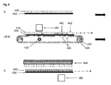
- Fig. 1A to Fig. 1C schematically illustrate a top view (A) and cross-sections (B, C) of photomasks (100) suitable for to the present invention.
- the photomasks (100) of Fig. 1A-C (not shown in Fig. 1B-C ) comprise windows (120) having the shape of indicia (stars and moons in Fig. 1A ) suitable to allow the curing by irradiation from an irradiation source (130) of a radiation curable coating composition on a substrate (150).
- the areas of the radiation curable coating composition facing the one or more windows of the photomask are cured as a result of the irradiation through the one or more windows.
- the areas of the radiation coating composition not facing the one or more windows of the photomask are not cured because the photomask material is blocking the radiation.
- the photomask described herein is an endless photomask, preferably a belt-shaped endless photomask being driven by at least two rollers.
- the substrate (150) is transported by the endless photomask (100), in particular a belt-shaped endless photomask.
- the endless photomask (100), in particular a belt-shaped endless photomask is driven by at least two rotating rollers (110) and bends around them.
- the belt-shaped endless photomask (100) described herein is driven by at least two rollers (110).
- the belt-shaped endless photomask bends around at least two rollers.
- the belt-shaped endless photomask described herein may be described as having a ratio (distance between the center of the two outmost rollers driving the belt)/(radius of the roller having the largest radius) greater than 1, preferably greater than 1.5 and even more preferably equal to or greater than 2.0.
- the outer surface of the belt-shaped endless photomask is substantially even for providing a direct surface contact and thus allowing the positioning of the substrate comprising the coating layer and allowing its direct contact with said substrate.
- the belt-shaped endless photomask is a timing belt (or toothed, or synchronous belt), which allows for very precise transmission of the rollers' movement.
- the rollers are driven by stepping motors controlled via a computer or any other motor control unit, and at least one circumferential edge of at least one roller is equipped with an array of detectors that work in a feedback loop with the motor control unit.
- the rollers may be driven by toothed belts or gears connected with the substrate feeder.
- the belt-shaped endless photomask comprises one or more windows to produce optical effect layers (OEL) comprising a motif made of at least two patterns having a different magnetic orientation pattern
- OEL optical effect layers
- the rollers and the belt are configured in such a way as to generate perfect register between the one or more windows and the substrate carrying the coating layer.
- the belt-shaped endless photomask may be further reinforced with threads or yarns for the supporting said belt.
- the belt-shaped endless photomask comprises a plurality of trapezoidal or V-shaped elements intended to improve transversal alignment and cancel the risk of sudden and complete belt failure.
- the belt-shaped endless photomask described herein is a continuous belt, i.e. a flexible single piece belt.
- the belt-shaped endless photomask described herein is preferably made of a non-magnetic flexible material preferably selected from the group consisting of non-magnetic metals, elastomers, thermoplastic polymers and mixtures thereof.
- Suitable non-magnetic metals include without limitation aluminum, cupper, cupper alloys (e.g. brass and bronze), stainless steel titanium, molybdene, molybdene alloys, tantalum and tantalum alloys.
- the belt-shaped endless photomask described herein is made of stainless steel or aluminum.
- the belt-shaped endless photomask described herein may be a silk-screen belt having the required transparent zone for the irradiation.
- Suitable elastomeric or thermoplastic polymers include without limitation natural rubber, synthetic rubbers like SBR (styrene-butadiene rubber), NBRs (nitrile-butadiene rubber), neoprenes (chloroprene rubber), polyvinylchlorides (PVC), PTFEs (Teflon®), polypropylenes (PP), polyamides (Nylon®), copolyetheresters as well as blends thereof.
- SBR styrene-butadiene rubber
- NBRs nitrile-butadiene rubber
- neoprenes chloroprene rubber
- PVC polyvinylchlorides
- PTFEs Teflon®
- PP polypropylenes
- nylon® polyamides
- copolyetheresters as well as blends thereof.
- the belt-shaped endless photomask described herein is a discontinuous belt or a chain-like belt-shaped endless photomask, i.e. an assembly comprising more than one pieces such as for example chain elements.
- the discontinuous belt-shaped endless photomask described herein preferably comprising more than one chain elements, said chain elements being either made of i) one or more engineering polymers or plastics including without limitation polyaryletherketones, polyacetals, polyamides, polyesters, polyethers, copolyetheresters, polyimides, polyetherimides, high-density polyethylene (HDPE), ultrahigh molecular weight polyethylene (UHMWPE), polybutylene terephthalate (PBT), polypropylene, acrylonitrile butadiene styrene (ABS) copolymer, fluorinated and perfluorinated polyethylenes, polystyrenes, polycarbonates, polyphenylenesulfide (PPS) and liquid crystal polymers,
- step c) The process described herein is performed by carrying out step c) subsequently to, partially simultaneously or simultaneously with step b).
- the time from the end of step b) to the beginning of step c) is preferably relatively short in order to avoid any de-orientation and loss of information.
- the time between the end of step b) and the beginning of step c) is less than 1 minute, preferably less than 20 seconds, further preferably less than 5 seconds. It is particularly preferable that there is essentially no time gap between the end of the orientation step b) and the beginning of the curing step c), i.e. that step c) follows immediately after step b) or already starts while step b) is still in progress (partially simultaneously or simultaneously).
- partially simultaneously it is meant that both steps are partly performed simultaneously, i.e. the times of performing each of the steps partially overlap.
- curing becomes effective after the orientation so that the pigment particles orient before the complete or partial curing of the OEL.
- Fig. 3 schematically illustrates an example of a process wherein step c) is carried subsequently to step b).
- the first magnetic-field-generating device (381) described herein may face the coating layer ( Fig. 3 , step j1) or may face the substrate (see Fig. 3 , step j2)).
- the process described herein is performed by carrying out partially simultaneously or simultaneously the two steps b) and c).
- the first magnetic-field-generating device described herein faces the coating layer and allow, for example, to produce optical effect layers (OEL) comprising a motif made of at least two patterns, wherein one of said at least two patterns is based on magnetic or magnetizable pigment particles oriented so as to follow a concave curvature when viewed from the side carrying the OEL, in particular a positive rolling bar feature as described hereabove.
- OEL optical effect layers
- the process described herein comprises a step d) of exposing the coating layer to the magnetic field of the second magnetic-field-generating device described herein thereby orienting at least another part of the magnetic or magnetizable pigment particles, said orientation taking place in one or more regions of the coating layer which are in the first state due to the presence of the photomask under step c).
- the second magnetic-field-generating device described herein faces the coating layer or, as shown in Fig. 3 , step I) and Fig. 4 step I), the second magnetic-field-generating device described herein faces the substrate.
- the process described herein is used to produce optical effect layers (OEL) comprising a motif made of at least two patterns, wherein one of said at least two patterns is based on magnetic or magnetizable pigment particles oriented so as to follow a concave curvature when viewed from the side carrying the OEL, in particular a positive rolling bar feature as described hereabove and the other of said at least two patterns is based on magnetic or magnetizable pigment particles oriented so as to follow a convex curvature when viewed from the side carrying the OEL, in particular a negative rolling bar.
- OEL optical effect layers
- OELS are produces by carrying out step b) with the first magnetic-field-generating device described herein facing the coating layer and the second magnetic-field-generating device facing the substrate.
- the process described herein comprises a step e) of curing with a second irradiation source the coating layer to a second state so as to fix the magnetic or magnetizable pigment particles in their adopted positions and orientations.
- the second irradiation source may be chosen among those described hereabove for the first irradiation source.
- the step e) of curing with the second irradiation source is carried out subsequently to the step d).
- the second magnetic-field-generating device described herein may face the coating layer or may face the substrate Fig. 3 , step j2).
- step e) of curing with the second irradiation source is preferably carried out partially simultaneously or simultaneously with the step d).
- step e) is carried out partially simultaneously or simultaneously with step d
- the second magnetic-field-generating device described herein faces the substrate (see Fig. 3 , step I) and Fig. 4 , step I)).
- FIG. 3 schematically illustrates a preferred example of a process suitable for forming an optical effect layer (OEL) using an endless photomask, in particular a belt-shaped endless photomask, according to the present invention.
- OEL optical effect layer
- an OEL based on magnetic or magnetizable pigment particles oriented so as to follow at least two different magnetic orientation patterns in adjacent regions may be produced by:
- a primer layer may be applied to the substrate prior to the step a). This may enhance the quality of the optical effect layer (OEL) described herein or promote adhesion. Examples of such primer layers may be found in WO 2010/058026 A2 .
- one or more protective layers may be applied on top of the optical effect layer (OEL).
- the one or more protective layers are typically made of protective varnishes. These may be transparent or slightly colored or tinted and may be more or less glossy.
- Protective varnishes may be radiation curable compositions, thermal drying compositions or any combination thereof.
- the one or more protective layers are radiation curable compositions, more preferable UV-Vis curable compositions.
- the protective layers are typically applied after the formation of the optical effect layer (OEL).
- the present invention further provides optical effect layers (OEL) produced by the process according to the present invention.
- OEL optical effect layers
- optical effect layer (OEL) described herein may be provided directly on a substrate on which it shall remain permanently (such as for banknote applications).
- an optical effect layer (OEL) may also be provided on a temporary substrate for production purposes, from which the OEL is subsequently removed. This may for example facilitate the production of the optical effect layer (OEL), particularly while the binder material is still in its fluid state. Thereafter, after curing the radiation curable coating composition for the production of the optical effect layer (OEL), the temporary substrate may be removed from the OEL.
- an adhesive layer may be present on the optical effect layer (OEL) or may be present on the substrate comprising OEL, said adhesive layer being on the side of the substrate opposite the side where the OEL is provided or on the same side as the OEL and on top of the OEL. Therefore an adhesive layer may be applied to the optical effect layer (OEL) or to the substrate, said adhesive layer being applied after the curing step has been completed.
- the substrate described herein comprising the optical effect layer (OEL) described herein may be in the form of a transfer foil, which can be applied to a document or to an article in a separate transfer step.
- the substrate is provided with a release coating, on which the optical effect layer (OEL) are produced as described herein.
- One or more adhesive layers may be applied over the so produced optical effect layer (OEL).
- substrates comprising more than one, i.e. two, three, four, etc. optical effect layers (OEL) obtained by the process described herein.
- OEL optical effect layers
- articles in particular security documents, decorative elements or objects, comprising the optical effect layer (OEL) produced according to the present invention.
- OEL optical effect layer
- the articles, in particular security documents, decorative elements or objects may comprise more than one (for example two, three, etc.) OELs produced according to the present invention.
- optical effect layer (OEL) produced according to the present invention may be used for decorative purposes as well as for protecting and authenticating a security document.
- Typical examples of decorative elements or objects include without limitation luxury goods, cosmetic packaging, automotive parts, electronic/electrical appliances, furniture and fingernail articles.
- Security documents include without limitation value documents and value commercial goods.
- value documents include without limitation banknotes, deeds, tickets, checks, vouchers, fiscal stamps and tax labels, agreements and the like, identity documents such as passports, identity cards, visas, driving licenses, bank cards, credit cards, transactions cards, access documents or cards, entrance tickets, public transportation tickets or titles and the like, preferably banknotes, identity documents, right-conferring documents, driving licenses and credit cards.
- value commercial good refers to packaging materials, in particular for cosmetic articles, nutraceutical articles, pharmaceutical articles, alcohols, tobacco articles, beverages or foodstuffs, electrical/electronic articles, fabrics or jewelry, i.e.
- packaging materials include without limitation labels, such as authentication brand labels, tamper evidence labels and seals. It is pointed out that the disclosed substrates, value documents and value commercial goods are given exclusively for exemplifying purposes, without restricting the scope of the invention.
- the optical effect layer may be produced onto an auxiliary substrate such as for example a security thread, security stripe, a foil, a decal, a window or a label and consequently transferred to a security document in a separate step.
- an auxiliary substrate such as for example a security thread, security stripe, a foil, a decal, a window or a label
- OEL optical effect layer
- the printing device described herein comprises a printing unit arranged to apply the coating composition on the substrate described herein.
- the printing unit is preferably selected from the group consisting of screen printing unit, rotogravure printing unit, flexography printing unit and intaglio printing unit, more preferably selected from the group consisting of screen printing unit, rotogravure printing unit and flexography printing unit.
- the printing devices described herein may comprise one or more of the first magnetic-field-generating devices described herein and/or one or more of the second magnetic-field-generating devices described herein comprised in a rotating magnetic cylinder wherein said one or more of the first magnetic-field-generating devices described herein and/or one or more of the second magnetic-field-generating devices described herein are mounted to circumferential grooves of the rotating magnetic cylinder.
- the rotating magnetic cylinder is part of a rotary, sheet-fed or web-fed industrial printing press that operates at high printing speed in a continuous way.
- the printing devices described herein may comprise one or more of the first magnetic-field-generating devices described herein and/or one or more of the second magnetic-field-generating devices described herein comprised in a flatbed printing unit comprising, wherein said one or more of the first magnetic-field-generating devices described herein and/or one or more of the second magnetic-field-generating devices described herein are mounted to recesses of the flatbed unit.
- the flatbed unit is meant to be used in, or in conjunction with, or being part of a printing unit, and bearing one or more of the devices described herein.
- the flatbed unit is part of a sheet-fed industrial printing press that operates in a discontinuous way.
- the first irradiation source and the second first irradiation source are selected as described hereabove.
- the second irradiation source is arranged so as to cure the coating composition on the substrate while it is exposed to the magnetic field of the second magnetic-field-generating device.
- Fig. 5 schematically illustrates a preferred example of a printing device for producing optical effect layers (OELs) on a substrate (550) such as those described herein according to the present invention, in particular according to the process described in Fig. 4 .
- a printing unit (570) arranged to apply the coating composition described herein on the substrate (550) described herein so as to form a coating layer (540) on the substrate (550), b) a belt-shaped endless photomask (500) such as those described herein moveable by at least two, in particular four, rollers (510), c) a first irradiation source (530) located within the loop formed by the belt-shaped endless photomask (500), d) a first magnetic-field-generating device (581) located in a first rotating magnetic cylinder (591), e) a second magnetic-field-generating device (582) located in a second rotating magnetic cylinder (592), and f) a second irradiation source curing unit (560).
- a printing unit (570) arranged to apply the coating composition described herein on the substrate (550) described herein so as to form a coating layer (540) on the substrate (550)
- a belt-shaped endless photomask (500) such as those described herein moveable by at
- OEL optical effect layer
- a cotton Banknote Paper from Louisenthal (hereafter referred as Louisenthal Velin) having a grammage of 90 g/m 2 such as those used in WO 2016/015973 A1 is used as a substrate for the example.
- a UV-curable coating composition described in Table 1 is applied on the substrate as a 10 mm x 15 mm rectangular pattern by hand using a T90 silkscreen so as to form a coating layer.
- Table 1 UV-curable screen printing ink
- Epoxyacrylate oligomer 36% Trimethylolpropane triacrylate monomer 13.5% Tripropyleneglycol diacrylate monomer 20% GenoradTM 16 (Rahn) 1% Aerosil ® 200 (Evonik) 1% Speedcure TPO-L (Lambson) 2%
- IRGACURE ® 500 BASF
- 6% Genocure EPD (Rahn) 2%
- Tego ® Foamex N Evonik
- Non-spherical optically variable magnetic pigment particles (7 layers)(*) 16.5% (*) gold-to-green optically variable magnetic pigment particles having a flake shape of diameter d50 about 9 ⁇ m and thickness about 1 ⁇ m, obtained from Viavi Solutions, Santa Rosa, CA.
- the substrate comprising the coating layer is disposed (direct contact) on a photomask made of aluminum (aluminum foil having a thickness of 0.2 mm) comprising a window having the shape of a five-branch star.
- a first magnetic-field-generating device (NdFeB N48 permanent magnetic bar, 30 x 18 x 6 mm) embedded in a housing (40 x 40 x 15 mm) made of polymer plastic (PPS), comprising on its surface a recess (20 x 20 mm with a depth of 1 mm) and facing the coating layer is used to orient the optically variable magnetic pigment particles to follow a concave curvature (positive curvature, positive rolling bar).
- the first magnetic-field-generating device is embedded in the center of the magnetic device housing at 6 mm from the housing surface opposite to the recess with its North-South axis being substantially parallel to coating layer. The distance between the first magnetic-field-generating device and the coating layer is 6 mm.
- a first irradiation source (a UV-LED-lamp from Phoseon, Type FireFlex 50x75 mm, 395 nm, 8 W/cm 2 ) is disposed below the photomask so as to cure, simultaneously or partially simultaneously with the orientation step, the coating layer in the areas facing the window and freeze the orientation of the optically variable magnetic pigment particles.
- the substrate is removed from the photomask.
- a second magnetic-field-generating device (same as the first magnetic-field-generating device) facing the substrate is used to orient the optically variable magnetic pigment particles which are still free to move and rotate in the area which is a not yet cured area due to the presence of the photomask to follow a convex curvature (negative curvature, negative rolling bar).
- the coating layer is cured by UV-Vis irradiation with a second irradiation source (same as the first irradiation source described hereabove), said second irradiation source being located on the side of the coating layer.
- the so-obtained optical effect layer comprises a motif made of two patterns made of a single cured layer, wherein one of said two patterns exhibit a positive rolling bar (within the 5-branch star) and the other of said two patterns exhibit a negative rolling bar due to a different magnetic orientation of the optically variable magnetic pigment particles of the two patterns.
Abstract
The present invention relates to the field of printing devices and processes for producing optical effect layers (OEL) comprising magnetically oriented magnetic or magnetizable pigment particles on a substrate. In particular, the present invention relates to printing devices and processes for producing said OELs as anti-counterfeit means on security documents or security articles or for decorative purposes.
Description
- The present invention relates to the field of the protection of value documents and value commercial goods against counterfeit and illegal reproduction. In particular, the present invention relates to optical effect layers (OELs) showing a viewing-angle dependent optical effect, magnetic assemblies and processes for producing said OELs, as well as uses of said OELs as anti-counterfeit means on documents.
- The use of inks, coating compositions, coatings, or layers, containing magnetic or magnetizable pigment particles, in particular non-spherical optically variable magnetic or magnetizable pigment particles, for the production of security elements and security documents is known in the art.
- Security features, e.g. for security documents, can be classified into "covert" and "overt" security features. The protection provided by covert security features relies on the principle that such features are hidden to the human senses, typically requiring specialized equipment and knowledge for their detection, whereas "overt" security features are easily detectable with the unaided human senses, e.g. such features may be visible and/or detectable via the tactile sense while still being difficult to produce and/or to copy. However, the effectiveness of overt security features depends to a great extent on their easy recognition as a security feature, because users will only then actually perform a security check based on such security feature if they are aware of its existence and nature.
- Coatings or layers comprising oriented magnetic or magnetizable pigment particles are disclosed for example in
US 2,570,856 ;US 3,676,273 ;US 3,791,864 ;US 5,630,877 andUS 5,364,689 . Magnetic or magnetizable pigment particles in coatings allow for the production of magnetically induced images, designs and/or patterns through the application of a corresponding magnetic field, resulting in a local orientation of the magnetic or magnetizable pigment particles in the unhardened coating, followed by hardening the latter. This results in specific optical effects, i.e. fixed magnetically induced images, designs or patterns which are highly resistant to counterfeit. The security elements based on oriented magnetic or magnetizable pigments particles can only be produced by having access to both the magnetic or magnetizable pigment particles or a corresponding ink or composition comprising said particles, and the particular technology employed to apply said ink or composition and to orient said pigment particles in the applied ink or composition. - For example,
US 7,047,883 discloses an apparatus and a method for producing optical effect layers (OELs), obtained by orienting magnetic or magnetizable optically variable pigment flakes in a coating composition; the disclosed apparatus consists in specific arrangements of permanent magnets placed under the substrate carrying said coating composition. According toUS 7,047,883 , a first portion of the magnetic or magnetizable optically variable pigment flakes in the OEL is oriented such as to reflect light in a first direction and a second portion adjacent to the first one is aligned such as to reflect light in a second direction, producing a visual "flip-flop" effect upon tilting the OEL. -
WO 2006/069218 A2 discloses a substrate comprising an OEL comprising optically variable magnetic or magnetizable pigment flakes, oriented in such a way that a bar appears to move when said OEL is tilted ("rolling bar"). According toWO 2006/069218 A2 , specific arrangements of permanent magnets under the substrate carrying the optically variable magnetic or magnetizable pigment flakes serve to orient said flakes such as to imitate a curved surface. - Other examples of a structure so-called "rolling bar" effect are disclosed in
US 2005/0106367 andUS 7,047,883 . A "rolling bar" feature is based on a pigment particles orientation imitating a curved surface across the coating and provides the optical illusion of movement upon tilting the feature. The observer sees a specular reflection zone which moves away or towards him as the image is tilted. A so-called positive rolling bar comprises pigment particles oriented in a concave way and follows a positively curved surface; a positive rolling bar moves with the rotation sense of tilting. A so-called negative rolling bar comprises pigment particles oriented in a convex way and follows a negatively curved surface; a negative rolling bar moves against the rotation sense of tilting. A hardened coating comprising pigment particles having an orientation following a concave curvature (positive curvature, shows a visual effect characterized by an upward movement of the rolling bar (positive rolling bar) when the support is tilted backwards. The concave curvature refers to the curvature as seen by an observer viewing the hardened coating from the side of the support carrying the hardened coating. A hardened coating comprising pigment particles having an orientation following a convex curvature (negative curvature) shows a visual effect characterized by a downward movement of the rolling bar (negative rolling bar) when the support carrying the hardened coating is tilted backwards (i.e. the top of the support moves away from the observer while the bottom of the support moves towards from the observer). This effect is nowadays utilized for a number of security elements on banknotes, such as on the "5" of the 5 Euro banknote or the "100" of the 100 Rand banknote of South Africa. - For optical effect layers printed on a substrate, negative rolling bar features (orientation of the pigment particles in a convex way) are produced by exposing a wet and not yet hardened coating layer to the magnetic field of a magnet located on the opposite side of the substrate to the coating layer, whereas positive rolling bar features (orientation of the pigment particles in a concave way) are produced by exposing a wet and not yet hardened coating layer to the magnetic field of a magnet located on the same side of the substrate as the coating layer.
-
WO 2016/015973 A1 discloses a process for producing optical effect layers (OEL) comprising a motif made of at least two areas made of a single hardened layer on a substrate. The process involves a step of exposing the coating layer comprising a plurality of magnetic or magnetizable pigment particles to a magnetic-field generating device and simultaneously or partially simultaneously hardening the coating layer to a second state so as to fix the magnetic or magnetizable pigment particles in their adopted positions and orientations, said hardening being performed through the substrate by irradiation with a UV-Vis radiation source located on the side of the substrate, said substrate being transparent to one or more wavelengths of the emission spectrum of the irradiation source. In one embodiment, the irradiation source is equipped with a photomask such that one or more substrate areas carrying the coating layer are not exposed to UV-Vis radiation. As shown inFig. 2 , a drawback of this process is the potential creation of shadow effect on the coating layer as a result of partially exposed areas arising from the optic geometry (width of radiation source (W1), distance of source to photomask (D1) and distance of photomask to coating layer (D2)) of the irradiation through windows of the photomask (as illustrated by the areas (W3) inFig. 2 ). - A need remains for improved processes for producing optical effect layers comprising a motif made of at least two patterns made of a single cured layer, wherein said processes involve using a photomask while avoiding the creation of areas displaying said shadow effects and remaining flexible.
- Accordingly, it is an object of the present invention to overcome the deficiencies of the prior art as discussed above.
- In a first aspect, the present invention provides a process for producing an optical effect layer (OEL) on a substrate (x50) and optical effect layers (OEL) obtained thereof, said process comprising the steps of:
- a) applying on the substrate (x50) a radiation curable coating composition comprising magnetic or magnetizable pigment particles so as to form a coating layer (x40), said coating layer being in a first state,
- b) exposing the coating layer (x40) to the magnetic field of a first magnetic-field-generating device (x81) thereby orienting at least part of the magnetic or magnetizable pigment particles,
- c) at least partially curing through the substrate (x50) and through one or more windows (x20) of a photomask (x00) the coating layer (x40) to a second state so as to fix the magnetic or magnetizable pigment particles in their adopted positions and orientations, wherein the at least partially curing is carried out by irradiation with a first irradiation source (x30) located on the side of the substrate (x50) and wherein the photomask (x00) is in direct contact with the substrate (x50),
- d) exposing the coating layer (x40) to the magnetic field of a second magnetic-field-generating device (x82) thereby orienting at least another part of the magnetic or magnetizable pigment particles, said orientation taking place in one or more regions of the coating layer (x40) which are in the first state due to the presence of the photomask (x00) under step c), and
- e) curing with a second irradiation source (x60) the coating layer (x40) to a second state so as to fix the magnetic or magnetizable pigment particles in their adopted positions and orientations,
- Also described herein are optical effect layers (OEL) produced by the process described herein as well as uses of said optical effect layers for the protection of a security document against counterfeiting or fraud as well as uses for a decorative application.
- Also described herein are security documents and decorative elements or objects comprising one or more optical effect layers (OELs) described herein.
- Also described herein are printing devices for producing optical effect layers (OEL) described herein, wherein the printing device comprises, a) a printing unit (x70), b) a photomask (x00) comprising one or more windows (x20), c) a first curing unit (x30), c) a first magnetic-field-generating device (x81), d) a second magnetic-field-generating device (x82); and e) a second curing unit (x60).
- In a further aspect, the present invention provides a use of the printing device described herein for producing the optical effect layer (OEL) described herein on a substrate such as those described herein.
-
- Fig. 1A
- schematically illustrates a top view of a photomask (100) comprising windows (120).
- Fig. 1B
- schematically illustrates a cross-section of a device comprising a photomask (100) comprising windows and an irradiation source (130) disposed below the surface of the photomask (100).
- Fig. 1C
- schematically illustrates a cross-section of a device comprising a belt-shaped endless photomask (100) comprising windows (120), b) two rollers (110) to move the photomask (100) and c) an irradiation source (130) disposed below the surface of the photomask.
- Fig. 2
- schematically illustrates an apparatus comprising a photomask used to produce an optical effect layer according to the prior art.
- Fig. 3
- schematically illustrates an example according to the present invention of a process using a belt-shaped endless photomask (300) driven by two rollers (310) and comprising windows (320), two magnetic-field generating devices (381 and 382) and two irradiation sources (330 and 360) suitable for forming an optical effect layer (OEL) made of a single cured layer.
- Fig. 4
- schematically illustrates another example according to the present invention of a process using a belt-shaped endless photomask (400) driven by four rollers (410) and comprising windows (420), two magnetic-field generating devices (481 and 482) and two irradiation sources (430 and 460) suitable for forming an optical effect layer (OEL).
- Fig. 5
- schematically illustrates another example according to the present invention of printing device comprising a printing unit (570) a belt-shaped endless photomask (500) driven by four rollers (510) and comprising windows (520), two magnetic-field generating devices (581 and 582) and two irradiation sources (530 and 560) suitable for forming an optical effect layer (OEL) on a substrate (550).
- The following definitions are to be used to interpret the meaning of the terms discussed in the description and recited in the claims.
- As used herein, the indefinite article "a" indicates one as well as more than one and does not necessarily limit its referent noun to the singular.
- As used herein, the term "about" means that the amount or value in question may be the specific value designated or some other value in its neighborhood. Generally, the term "about" denoting a certain value is intended to denote a range within ± 5% of the value. As one example, the phrase "about 100" denotes a range of 100 ± 5, i.e. the range from 95 to 105. Generally, when the term "about" is used, it can be expected that similar results or effects according to the invention can be obtained within a range of ±5% of the indicated value.
- As used herein, the term "and/or" means that either all or only one of the elements of said group may be present. For example, "A and/or B" shall mean "only A, or only B, or both A and B". In the case of "only A", the term also covers the possibility that B is absent, i.e. "only A, but not B".
- The term "comprising" as used herein is intended to be non-exclusive and open-ended. Thus, for instance a fountain solution comprising a compound A may include other compounds besides A. However, the term "comprising" also covers, as a particular embodiment thereof, the more restrictive meanings of "consisting essentially of" and "consisting of", so that for instance "a fountain solution comprising A, B and optionally C" may also (essentially) consist of A and B, or (essentially) consist of A, B and C.
- The term "coating composition" refers to any composition which is capable of forming an optical effect layer (OEL) of the present invention on a solid substrate and which can be applied preferably but not exclusively by a printing method. The coating composition comprises magnetic or magnetizable pigment particles and a binder.
- The term "optical effect layer (OEL)" as used herein denotes a layer that comprises magnetic or magnetizable pigment particles and a binder, wherein the orientation of the magnetic or magnetizable pigment particles is fixed or frozen (fixed/frozen) within the binder.
- The term "rolling bar" or "rolling bar feature" denotes an area within the OEL that provides the optical effect or optical impression of a cylindrical bar shape lying crosswise within the OEL, with the axis of the cylindrical bar lying parallel to the plane of the OEL and the part of the curved surface of the cylindrical bar being above the plane of the OEL. The "rolling bar", i.e. the cylindrical bar shape, can be symmetrical or non-symmetrical, i.e. the radius of the cylindrical bar may be constant or not constant; when the radius of the cylindrical bar is not constant, the rolling bar has a conical form.
- The terms "convex way" or "convex curvature" and the terms "concave way" or "concave curvature" refer to the curvature of a Fresnel surface across the OEL that provides the optical effect or the optical impression of a rolling bar. A Fresnel surface is a flat surface comprising micro-structures with changing slope angles. At the position where the OEL is produced, the magnetic-field-generating device orients the magnetic or magnetizable pigment particles following the tangent to the curved surface. The terms "convex way" or "convex curvature" and the terms "concave way" or "concave curvature" refer to the apparent curvature of the curved surface as seen by an observer viewing the optical effect layer OEL from the side of the substrate carrying the OEL
- The term "curing" is used to denote a process wherein the viscosity of a coating composition is increased so as to convert it into a state, i.e. a hardened or solid state, where the magnetic or magnetizable pigment particles are fixed/frozen in their current positions and orientations and can no longer move nor rotate.
- Where the present description refers to "preferred" embodiments/features, combinations of these "preferred" embodiments/features shall also be deemed as disclosed as long as this combination of "preferred" embodiments/features is technically meaningful.
- As used herein, the term "at least" is meant to define one or more than one, for example one or two or three.
- The term "security document" refers to a document which is usually protected against counterfeit or fraud by at least one security feature. Examples of security documents include without limitation value documents and value commercial goods.
- The term "security feature" is used to denote an image, pattern or graphic element that can be used for authentication purposes.
- The present invention provides a process for producing an optical effect layer (OEL) comprising a motif made of at least two patterns made of a single cured layer, wherein said two patterns have a different magnetic orientation of the magnetic or magnetizable pigment particles, and wherein the magnetic or magnetizable pigment particles are oriented in said at least two patterns in any pattern except a random orientation. The desired orientation of the magnetic or magnetizable pigment particles of the one and at least the other of the at least two patterns can be freely chosen according to the end-use applications. The at least two patterns described herein may be spaced apart or may be adjacent, preferably the at least two patterns described herein are adjacent.
- Examples of any pattern except a random orientation include without limitation rolling bar features, flip-flop effects (also referred in the art as switching effect), Venetian-blind effects, moving-ring effects. Flip-flop effects include a first printed pattern and a second printed pattern separated by a transition, wherein pigment particles are aligned parallel to a first plane in the first pattern and pigment particles in the second pattern are aligned parallel to a second plane. Methods for producing flip-flop effects are disclosed for example in
EP 1 819 525 B1EP 1 819 525 B1US 8,025,952 andEP 1 819 525 B1EP 1 710 756 A1US 8,343,615 ,EP 2 306 222 A1 ,EP 2 325 677 A2 ,WO 2011/092502 A2 ,US 2013/084411 ,WO 2014/108 404 A2 andWO 2014/108303 A2 . - The process described herein comprises a step a) of applying, preferably with the printing unit described herein, on the substrate described herein the coating composition comprising magnetic or magnetizable pigment particles described herein so as to form a coating layer, said coating composition being in a first state (see steps i) of
Fig. 3 andFig. 4 ). Preferably, said step is carried out by a printing process preferably selected from the group consisting of screen printing, rotogravure printing, flexography printing, inkjet printing and intaglio printing (also referred in the art as engraved copper plate printing and engraved steel die printing), more preferably selected from the group consisting of screen printing, rotogravure printing and flexography printing. - Screen printing (also referred in the art as silkscreen printing) is a stencil process whereby an ink is transferred to a surface through a stencil supported by a fine fabric mesh of silk, mono- or multifilaments made of synthetic fibers such as for example polyamides or polyesters or metal threads stretched tightly on a frame made for example of wood or a metal (e.g. aluminum or stainless steel). Alternatively, the screen-printing mesh may be a chemically etched, a laser-etched, or a galvanically formed porous metal foil, e.g. a stainless steel foil. The pores of the mesh are blocked in the non-image areas and left open in the image area, the image carrier being called the screen. Screen printing might be of the flat-bed or rotary type. Screen printing is further described for example in The Printing ink manual, R.H. Leach and R.J. Pierce, Springer Edition, 5th Edition, pages 58-62 and in Printing Technology, J.M. Adams and P.A. Dolin, Delmar Thomson Learning, 5th Edition, pages 293-328.
- Rotogravure (also referred in the art as gravure) is a printing process wherein the image elements are engraved into the surface of a cylinder. The non-image areas are at a constant original level. Prior to printing, the entire printing plate (non-printing and printing elements) is inked and flooded with ink. Ink is removed from the non-image by a wiper or a blade before printing, so that ink remains only in the cells. The image is transferred from the cells to the substrate by a pressure typically in the range of 2 to 4 bars and by the adhesive forces between the substrate and the ink. The term rotogravure does not encompass intaglio printing processes (also referred in the art as engraved steel die or copper plate printing processes) which rely for example on a different type of ink. More details are provided in "Handbook of print media", Helmut Kipphan, Springer Edition, page 48 and in The Printing ink manual, R.H. Leach and R.J. Pierce, Springer Edition, 5th Edition, pages 42-51.
- Flexography preferably uses a unit with a doctor blade, preferably a chambered doctor blade, an anilox roller and plate cylinder. The anilox roller advantageously has small cells whose volume and/or density determines the ink application rate. The doctor blade lies against the anilox roller, and scraps off surplus ink at the same time. The anilox roller transfers the ink to the plate cylinder which finally transfers the ink to the substrate. Specific design might be achieved using a designed photopolymer plate. Plate cylinders can be made from polymeric or elastomeric materials. Polymers are mainly used as photopolymer in plates and sometimes as a seamless coating on a sleeve. Photopolymer plates are made from light-sensitive polymers that are hardened by ultraviolet (UV) light. Photopolymer plates are cut to the required size and placed in an UV light exposure unit. One side of the plate is completely exposed to UV light to harden or cure the base of the plate. The plate is then turned over, a negative of the job is mounted over the uncured side and the plate is further exposed to UV light. This hardens the plate in the image areas. The plate is then processed to remove the unhardened photopolymer from the nonimage areas, which lowers the plate surface in these nonimage areas. After processing, the plate is dried and given a post-exposure dose of UV light to cure the whole plate. Preparation of plate cylinders for flexography is described in Printing Technology, J. M. Adams and P.A. Dolin, Delmar Thomson Learning, 5th Edition, pages 359-360 and in The Printing ink manual, R.H. Leach and R.J. Pierce, Springer Edition, 5th Edition, pages 33-42.
- The radiation curable coating composition described herein as well as the coating layer described herein comprise magnetic or magnetizable pigment particles, preferably non-spherical magnetic or magnetizable pigment particles. Preferably, the magnetic or magnetizable pigment particles described herein are present in an amount from about 5 wt-% to about 40 wt-%, more preferably about 10 wt-% to about 30 wt-%, the weight percentages being based on the total weight of the radiation curable coating composition.
- Non-spherical magnetic or magnetizable pigment particles described herein are defined as having, due to their non-spherical shape, non-isotropic reflectivity with respect to an incident electromagnetic radiation for which the hardened/cured binder material is at least partially transparent. As used herein, the term "non-isotropic reflectivity" denotes that the proportion of incident radiation from a first angle that is reflected by a particle into a certain (viewing) direction (a second angle) is a function of the orientation of the particles, i.e. that a change of the orientation of the particle with respect to the first angle can lead to a different magnitude of the reflection to the viewing direction. The non-spherical magnetic or magnetizable pigment particles are preferably prolate or oblate ellipsoid-shaped, platelet-shaped or needle-shaped particles or a mixture of two or more thereof and more preferably platelet-shaped particles.
- Suitable examples of magnetic or magnetizable pigment particles, in particular non-spherical magnetic or magnetizable pigment particles, described herein include without limitation pigment particles comprising a magnetic metal selected from the group consisting of cobalt (Co), iron (Fe), gadolinium (Gd) and nickel (Ni); a magnetic alloy of iron, manganese, cobalt, nickel or a mixture of two or more thereof; a magnetic oxide of chromium, manganese, cobalt, iron, nickel or a mixture of two or more thereof; or a mixture of two or more thereof. The term "magnetic" in reference to the metals, alloys and oxides is directed to ferromagnetic or ferrimagnetic metals, alloys and oxides. Magnetic oxides of chromium, manganese, cobalt, iron, nickel or a mixture of two or more thereof may be pure or mixed oxides. Examples of magnetic oxides include without limitation iron oxides such as hematite (Fe2O3), magnetite (Fe3O4), chromium dioxide (CrO2), magnetic ferrites (MFe2O4), magnetic spinels (MR2O4), magnetic hexaferrites (MFe12O19), magnetic orthoferrites (RFeO3), magnetic garnets M3R2(AO4)3, wherein M stands for two-valent metal, R stands for three-valent metal, and A stands for four-valent metal.
- Examples of magnetic or magnetizable pigment particles, in particular non-spherical magnetic or magnetizable pigment particles, described herein include without limitation pigment particles comprising a magnetic layer M made from one or more of a magnetic metal such as cobalt (Co), iron (Fe), gadolinium (Gd) or nickel (Ni); and a magnetic alloy of iron, cobalt or nickel, wherein said magnetic or magnetizable pigment particles may be multilayered structures comprising one or more additional layers. Preferably, the one or more additional layers are layers A independently made from one or more selected from the group consisting of metal fluorides such as magnesium fluoride (MgF2), silicium oxide (SiO), silicium dioxide (SiO2), titanium oxide (TiO2), and aluminum oxide (Al2O3), more preferably silicium dioxide (SiO2); or layers B independently made from one or more selected from the group consisting of metals and metal alloys, preferably selected from the group consisting of reflective metals and reflective metal alloys, and more preferably selected from the group consisting of aluminum (Al), chromium (Cr), and nickel (Ni), and still more preferably aluminum (Al); or a combination of one or more layers A such as those described hereabove and one or more layers B such as those described hereabove. Typical examples of the magnetic or magnetizable pigment particles being multilayered structures described hereabove include without limitation A/M multilayer structures, A/M/A multilayer structures, A/M/B multilayer structures, A/B/M/A multilayer structures, A/B/M/B multilayer structures, A/B/M/B/A/multilayer structures, B/M multilayer structures, B/M/B multilayer structures, B/A/M/A multilayer structures, B/A/M/B multilayer structures, B/A/M/B/A/multilayer structures, wherein the layers A, the magnetic layers M and the layers B are chosen from those described hereabove.
- The coating composition described herein may comprise optically variable magnetic or magnetizable pigment particles, in particular non-spherical optically variable magnetic or magnetizable pigment particles, and/or non-spherical magnetic or magnetizable pigment particles, in particular non-spherical, having no optically variable properties. Preferably, at least a part of the magnetic or magnetizable pigment particles described herein is constituted by optically variable magnetic or magnetizable pigment particles, in particular non-spherical optically variable magnetic or magnetizable pigment particles. In addition to the overt security provided by the colorshifting property of the optically variable magnetic or magnetizable pigment particles, which allows easily detecting, recognizing and/or discriminating an article or security document carrying an ink, coating composition, or coating layer comprising the optically variable magnetic or magnetizable pigment particles described herein from their possible counterfeits using the unaided human senses, the optical properties of the optically variable magnetic or magnetizable pigment particles may also be used as a machine readable tool for the recognition of the OEL. Thus, the optical properties of the optically variable magnetic or magnetizable pigment particles may simultaneously be used as a covert or semi-covert security feature in an authentication process wherein the optical (e.g. spectral) properties of the pigment particles are analyzed.
- The use of optically variable magnetic or magnetizable pigment particles, in particular optically variable magnetic or magnetizable pigment particles, in coating layers for producing an OEL enhances the significance of the OEL as a security feature in security document applications, because such materials are reserved to the security document printing industry and are not commercially available to the public.
- As mentioned above, preferably at least a part of the magnetic or magnetizable pigment particles is constituted by optically variable magnetic or magnetizable pigment particles, in particular non-spherical optically variable magnetic or magnetizable pigment particles. These are more preferably selected from the group consisting of magnetic thin-film interference pigment particles, magnetic cholesteric liquid crystal pigment particles, interference coated pigment particles comprising a magnetic material and mixtures of two or more thereof. The magnetic thin-film interference pigment particles, magnetic cholesteric liquid crystal pigment particles and interference coated pigment particles comprising a magnetic material described herein are preferably prolate or oblate ellipsoid-shaped, platelet-shaped or needle-shaped particles or a mixture of two or more thereof and more preferably platelet-shaped particles.
- Magnetic thin film interference pigment particles are known to those skilled in the art and are disclosed e.g. in
US 4,838,648 ;WO 2002/073250 A2 ;EP 0 686 675 B1 ;WO 2003/000801 A2 ;US 6,838,166 ;WO 2007/131833 A1 ;EP 2 402 401 A1 and in the documents cited therein. Preferably, the magnetic thin film interference pigment particles comprise pigment particles having a five-layer Fabry-Perot multilayer structure and/or pigment particles having a six-layer Fabry-Perot multilayer structure and/or pigment particles having a seven-layer Fabry-Perot multilayer structure. - Preferred five-layer Fabry-Perot multilayer structures consist of absorber/dielectric/reflector/dielectric/absorber multilayer structures wherein the reflector and/or the absorber is also a magnetic layer, preferably the reflector and/or the absorber is a magnetic layer comprising nickel, iron and/or cobalt, and/or a magnetic alloy comprising nickel, iron and/or cobalt and/or a magnetic oxide comprising nickel (Ni), iron (Fe) and/or cobalt (Co).
- Preferred six-layer Fabry-Perot multilayer structures consist of absorber/dielectric/reflector/magnetic/dielectric/absorber multilayer structures.
- Preferred seven-layer Fabry Perot multilayer structures consist of absorber/dielectric/reflector/magnetic/reflector/dielectric/absorber multilayer structures such as disclosed in
US 4,838,648 . - Preferably, the reflector layers described herein are independently made from one or more selected from the group consisting of metals and metal alloys, preferably selected from the group consisting of reflective metals and reflective metal alloys, more preferably selected from the group consisting of aluminum (Al), silver (Ag), copper (Cu), gold (Au), platinum (Pt), tin (Sn), titanium (Ti), palladium (Pd), rhodium (Rh), niobium (Nb), chromium (Cr), nickel (Ni), and alloys thereof, even more preferably selected from the group consisting of aluminum (Al), chromium (Cr), nickel (Ni) and alloys thereof, and still more preferably aluminum (Al). Preferably, the dielectric layers are independently made from one or more selected from the group consisting of metal fluorides such as magnesium fluoride (MgF2), aluminum fluoride (AlF3), cerium fluoride (CeF3), lanthanum fluoride (LaF3), sodium aluminum fluorides (e.g. Na3AlF6), neodymium fluoride (NdF3), samarium fluoride (SmF3), barium fluoride (BaF2), calcium fluoride (CaF2), lithium fluoride (LiF), and metal oxides such as silicium oxide (SiO), silicium dioxide (SiO2), titanium oxide (TiO2), aluminum oxide (Al2O3), more preferably selected from the group consisting of magnesium fluoride (MgF2) and silicium dioxide (SiO2) and still more preferably magnesium fluoride (MgF2). Preferably, the absorber layers are independently made from one or more selected from the group consisting of aluminum (Al), silver (Ag), copper (Cu), palladium (Pd), platinum (Pt), titanium (Ti), vanadium (V), iron (Fe) tin (Sn), tungsten (W), molybdenum (Mo), rhodium (Rh), Niobium (Nb), chromium (Cr), nickel (Ni), metal oxides thereof, metal sulfides thereof, metal carbides thereof, and metal alloys thereof, more preferably selected from the group consisting of chromium (Cr), nickel (Ni), metal oxides thereof, and metal alloys thereof, and still more preferably selected from the group consisting of chromium (Cr), nickel (Ni), and metal alloys thereof. Preferably, the magnetic layer comprises nickel (Ni), iron (Fe) and/or cobalt (Co); and/or a magnetic alloy comprising nickel (Ni), iron (Fe) and/or cobalt (Co); and/or a magnetic oxide comprising nickel (Ni), iron (Fe) and/or cobalt (Co). When magnetic thin film interference pigment particles comprising a seven-layer Fabry-Perot structure are preferred, it is particularly preferred that the magnetic thin film interference pigment particles comprise a seven-layer Fabry-Perot absorber/dielectric/reflector/magnetic/reflector/dielectric/absorber multilayer structure consisting of a Cr/MgF2/Al/Ni/Al/MgF2/Cr multilayer structure.
- The magnetic thin film interference pigment particles described herein may be multilayer pigment particles being considered as safe for human health and the environment and being based for example on five-layer Fabry-Perot multilayer structures, six-layer Fabry-Perot multilayer structures and seven-layer Fabry-Perot multilayer structures, wherein said pigment particles include one or more magnetic layers comprising a magnetic alloy having a substantially nickel-free composition including about 40 wt-% to about 90 wt-% iron, about 10 wt-% to about 50 wt-% chromium and about 0 wt-% to about 30 wt-% aluminum. Typical examples of multilayer pigment particles being considered as safe for human health and the environment can be found in
EP 2 402 401 A1 whose content is hereby incorporated by reference in its entirety. - Magnetic thin film interference pigment particles described herein are typically manufactured by a conventional deposition technique of the different required layers onto a web. After deposition of the desired number of layers, e.g. by physical vapor deposition (PVD), chemical vapor deposition (CVD) or electrolytic deposition, the stack of layers is removed from the web, either by dissolving a release layer in a suitable solvent, or by stripping the material from the web. The so-obtained material is then broken down to flakes which have to be further processed by grinding, milling (such as for example jet milling processes) or any suitable method so as to obtain pigment particles of the required size. The resulting product consists of flat flakes with broken edges, irregular shapes and different aspect ratios. Further information on the preparation of suitable magnetic thin film interference pigment particles can be found e.g. in
EP 1 710 756 A1EP 1 666 546 A1 - Suitable magnetic cholesteric liquid crystal pigment particles exhibiting optically variable characteristics include without limitation magnetic monolayered cholesteric liquid crystal pigment particles and magnetic multilayered cholesteric liquid crystal pigment particles. Such pigment particles are disclosed for example in
WO 2006/063926 A1 ,US 6,582,781 andUS 6,531,221 .WO 2006/063926 A1 discloses monolayers and pigment particles obtained therefrom with high brilliance and colorshifting properties with additional particular properties such as magnetizability. The disclosed monolayers and pigment particles, which are obtained therefrom by comminuting said monolayers, include a three-dimensionally crosslinked cholesteric liquid crystal mixture and magnetic nanoparticles.US 6,582,781 andUS 6,410,130 disclose platelet-shaped cholesteric multilayer pigment particles which comprise the sequence A1/B/A2, wherein A1 and A2 may be identical or different and each comprises at least one cholesteric layer, and B is an interlayer absorbing all or some of the light transmitted by the layers A1 and A2 and imparting magnetic properties to said interlayer.US 6,531,221 discloses platelet-shaped cholesteric multilayer pigment particles which comprise the sequence A/B and optionally C, wherein A and C are absorbing layers comprising pigment particles imparting magnetic properties, and B is a cholesteric layer. - Suitable interference coated pigments comprising one or more magnetic materials include without limitation structures consisting of a substrate selected from the group consisting of a core coated with one or more layers, wherein at least one of the core or the one or more layers have magnetic properties. For example, suitable interference coated pigments comprise a core made of a magnetic material such as those described hereabove, said core being coated with one or more layers made of one or more metal oxides, or they have a structure consisting of a core made of synthetic or natural micas, layered silicates (e.g. talc, kaolin and sericite), glasses (e.g. borosilicates), silicium dioxides (SiO2), aluminum oxides (Al2O3), titanium oxides (TiO2), graphites and mixtures of two or more thereof. Furthermore, one or more additional layers such as coloring layers may be present.
- The magnetic or magnetizable pigment particles described herein may be surface treated so as to protect them against any deterioration that may occur in the coating composition and coating layer and/or to facilitate their incorporation in said coating composition and coating layer; typically corrosion inhibitor materials and/or wetting agents may be used.
- The process described herein further comprises two steps of exposing the coating layer described herein to the magnetic field of a first magnetic-field-generating device and a second magnetic-field-generating device.
- The process described herein further comprises two steps of curing the coating layer, wherein said curing allows to convert the radiation curable coating composition from a first state (still wet and not yet hardened or cured so that the magnetic or magnetizable pigment particles are free to move, rotate and orient themselves) into a second state, i.e. a hardened, cured or solid state, where the magnetic or magnetizable pigment particles are fixed/frozen in their current positions and orientations and can no longer move nor rotate. One of the two steps is carried out by irradiating through the substrate and through the one or more windows of the photomask which is in direct contact with the substrate with a first irradiation source located on the side of the substrate so as to fix the magnetic or magnetizable pigment particles in their adopted positions and orientations in the area(s) carrying the coating layer which was(were) exposed to the irradiation due to the presence of the one or more windows of the photomask and the other of the two steps is carried out with a second irradiation source located on the side of the coating layer or on the side of the substrate (depending on the desired orientation of the magnetic or magnetizable pigment particles and the end-use application.)
- The first and second states described herein can be provided by using a binder material that shows a great increase in viscosity in reaction to an exposure to electromagnetic radiation, such as for example UV-Vis region. That is, when the fluid binder material is hardened or cured, said binder material converts into the second state, i.e. a hardened, cured or solid state, where the magnetic or magnetizable pigment particles are fixed in their positions and orientations and can no longer move nor rotate within the binder material. As known to those skilled in the art, ingredients comprised in a radiation curable coating composition and coating layer obtained thereof on the substrate described herein and the physical properties of said coating layer are determined by the nature of the process used to transfer the radiation curable coating composition to the substrate. Consequently, suitable binder material for the present invention are typically chosen among those known in the art and depends on the coating or printing process used to apply the radiation curable coating composition.
- Preferably, the binder of the radiation curable coating compositions described herein is a UV-Vis curable coating composition preferably prepared from oligomers (also referred in the art as prepolymers) selected from the group consisting of radically curable compounds, cationically curable compounds and mixtures thereof. Cationically curable compounds are hardened by cationic mechanisms consisting of the activation by energy of one or more photoinitiators which liberate cationic species, such as acids, which in turn initiate the polymerization so as to form the binder. Radically curable compounds are cured by free radical mechanisms consisting of the activation by energy of one or more photoinitiators which liberate free radicals which in turn initiate the polymerization so as to form the binder.
- UV-Vis curing of a monomer, oligomer or prepolymer may require the presence of one or more photoinitiators and may be performed in a number of ways. As known by those skilled in the art, the one or more photoinitiators are selected according to their absorption spectra and are selected to fit with the emission spectra of the irradiation source. Depending on the monomers, oligomers or prepolymers used to prepare the binder comprised in the UV-Vis curable coating compositions described herein, different photoinitiators might be used. Suitable examples of free radical photoinitiators are known to those skilled in the art and include without limitation acetophenones, benzophenones, alpha-aminoketones, alpha-hydroxyketones, phosphine oxides and phosphine oxide derivatives and benzyldimethyl ketals. Suitable examples of cationic photoinitiators are known to those skilled in the art and include without limitation onium salts such as organic iodonium salts (e.g. diaryl iodoinium salts), oxonium (e.g. triaryloxonium salts) and sulfonium salts (e.g. triarylsulphonium salts). It may also be advantageous to include a sensitizer in conjunction with the one or more photoinitiators in order to achieve efficient curing. Typical examples of suitable photosensitizers include without limitation isopropyl-thioxanthone (ITX), 1-chloro-2-propoxy-thioxanthone (CPTX), 2-chloro-thioxanthone (CTX) and 2,4-diethyl-thioxanthone (DETX) and mixtures thereof. The one or more photoinitiators comprised in the UV-Vis curable coating compositions are preferably present in an amount from about 0.1 wt-% to about 20 wt-%, more preferably about 1 wt-% to about 15 wt-%, the weight percents being based on the total weight of the UV-Vis curable coating compositions.
- The radiation curable coating compositions described herein may further comprise one or more additives including without limitation compounds and materials which are used for adjusting physical, rheological and chemical parameters of the composition such as the viscosity (e.g. solvents and surfactants), the consistency (e.g. anti-settling agents, fillers and plasticizers), the foaming properties (e.g. antifoaming agents), the lubricating properties (waxes), UV reactivity and stability (photosensitizers and photostabilizers) and adhesion properties, etc. Additives described herein may be present in the coating compositions described herein in amounts and in forms known in the art, including in the form of so-called nano-materials where at least one of the dimensions of the particles is in the range of 1 to 1000 nm.
- The radiation curable coating composition described herein may further comprise one or more marker substances or taggants and/or one or more machine readable materials selected from the group consisting of magnetic materials (different from the magnetic or magnetizable pigment particles described herein), luminescent materials, electrically conductive materials and infrared-absorbing materials. As used herein, the term "machine readable material" refers to a material which exhibits at least one distinctive property which is detectable by a device or a machine, and which can be comprised in a coating so as to confer a way to authenticate said coating or article comprising said coating by the use of a particular equipment for its detection and/or authentication.
- The radiation curable coating compositions described herein may be prepared by dispersing or mixing the magnetic or magnetizable pigment particles described herein and the one or more additives when present in the presence of the binder material described herein, thus forming liquid compositions. When present, the one or more photoinitiators may be added to the composition either during the dispersing or mixing step of all other ingredients or may be added at a later stage, i.e. after the formation of the liquid coating composition.
- Since the step c) of at least partially curing the coating layer is carried out through the substrate, suitable substrates for the present invention are transparent to one or more wavelengths of the emission spectrum of at least the first irradiation source, preferably a UV-Vis irradiation source, used to cure the radiation curable coating composition on said substrates, i.e. the substrates must exhibit transmission of electromagnetic radiations of at least 4 %, preferably at least 8% at one or more wavelengths of the emission spectrum of the irradiation source in the range of 200 nm to 500 nm. As mentioned herein and as known by the man skilled in the art, the radiation curable coating compositions to be cured on the substrate comprise one or more photoinitiators optionally with one or more photosensitizers, said one or more photoinitiators and optional one or more photosensitizers being selected according to its/their absorption spectrum/spectra in correlation with the emission spectrum of the irradiation sources. Depending on the degree of transmission of the electromagnetic radiation through the substrate, curing of the radiation curable coating layer may be obtained by increasing the irradiation time. However, depending on the substrate material, the irradiation time is limited by the substrate material and its sensitivity to the heat produced by the irradiation source. The curing the radiation curable coating composition on the substrate described herein is effected with light of a wavelength from about 200 nm to about 500 nm. A large number of widely varying types of irradiation sources may be used. Point sources and also planiform radiators (lamp carpets are suitable). Examples thereof include without limitation carbon arc lamps, xenon arc lamps, medium-, high- and low-pressure mercury lamps, doped where appropriate with metal halides (metal halides lamps), microwave-excited metal vapor lamps, excimer lamps, superactinid fluorescent tubes, fluorescent lamps, argon incandescent lamps, flashlamps, photographic flood lights and light emitting diodes (LED). The transmission of the radiation through the substrates may be measured as described in
WO 2016/015973 A1 (Perkin Elmer Lambda 950 equipped with a Deuterium (UV) and a Xenon (VIS) lamp and a UV WinLab Data Processor. Measurement mode: integration sphere transmission. The transmission spectra were measured for the range between 250 nm and 500 nm). - The substrate described herein is preferably selected from the group consisting of papers or other fibrous materials such as cellulose, paper-containing materials, glasses, ceramics, plastics and polymers, composite materials and mixtures or combinations thereof, provided that the substrate is transparent to one or more wavelengths of the emission spectrum of at least the first irradiation source used to cure the coating composition. Typical paper, paper-like or other fibrous materials are made from a variety of fibers including without limitation abaca, cotton, linen, wood pulp, and blends thereof. As is well known to those skilled in the art, cotton and cotton/linen blends are preferred for banknotes, while wood pulp is commonly used in non-fiduciary documents. The substrate may be coated with a primer, provided that the substrate is transparent to one or more wavelengths of the emission spectrum of at least the first irradiation source used to cure the coating composition. Examples of such primer are disclosed e.g. in
WO 2010/058026 A2 . Typical examples of plastics and polymers include polyolefins such as polyethylene (PE) and polypropylene (PP) including biaxially oriented polypropylene (BOPP), polyamides, polyesters such as poly(ethylene terephthalate) (PET), poly(1,4-butylene terephthalate) (PBT), poly(ethylene 2,6-naphthoate) (PEN) and polyvinylchlorides (PVC). Spunbond olefin fibers such as those sold under the trademark Tyvek® may also be used as substrate. Typical examples of composite materials include without limitation multilayer structures or laminates of paper and at least one plastic or polymer material such as those described hereabove as well as plastic and/or polymer fibers incorporated in a paper-like or fibrous material such as those described hereabove. Of course, the substrate can comprise further additives that are known to the skilled person, such as sizing agents, whiteners, processing aids, reinforcing or wet strengthening agents etc., provided that the substrate is transparent to one or more wavelengths of the emission spectrum of at least the irradiation source used to cure the coating composition. - The process described herein comprises a step b) of exposing coating layer to the magnetic field of the first magnetic-field-generating device described herein, thereby orienting at least part of the magnetic or magnetizable pigment particles
- According to one embodiment and as shown in
Fig 3 , step j1) andFig. 4 , step j&k), the first magnetic-field-generating device (381 and 481, respectively) described herein may face the coating composition. For example, the first magnetic-field-generating device described herein may face the coating composition so as to form a pattern exhibiting a concave rolling-bar, i.e. the optical effect layers (OEL) comprises a motif made of at least two patterns, wherein one of said at least two patterns is based on magnetic or magnetizable pigment particles oriented so as to follow a concave curvature when viewed from the side carrying the OEL, in particular a positive rolling bar feature, and another of said at least two patterns is based on a plurality of magnetic or magnetizable pigment particles oriented in any pattern except a random orientation. According to another embodiment and as shown inFig 3 , step j2), the first magnetic-field-generating device (381) described herein may face the substrate. - The process described herein comprises a step c) of at least partially curing through the substrate described herein and through the one or more windows of the photomask (which is in direct contact with the substrate) the coating layer to a second state so as to fix the magnetic or magnetizable pigment particles in their adopted positions and orientations, said curing being performed by irradiation with a first irradiation source located on the side of the substrate.
- The present invention advantageously uses photomasks to produce the optical effect layers (OELs) described herein. Photomasks in the field of security printing have been used and are described in
WO 2016/015973 A1 .Fig. 2 schematically illustrates a curing device for producing optical effect layers (OELs) according to the prior art. The curing device comprises an irradiation source (235) having a width (W1) and a photomask (205) comprising at least one window. A substrate (250) carrying a radiation curable coating composition (240) is at least partially cured by the irradiation source (235). The photomask (205) is placed at a distance (D2) from the substrate (250) surface. The irradiation source (235) is located at a distance (D1) from the photomask (205). Due to optic geometry, the radiation curable coating composition (240) receives full irradiation in the area (W2) located directly in front of the photomask window, and partial irradiation in the border areas (W3) resulting only in partial curing of the radiation curable coating composition in the border areas (W3) and only partial fixing/frozing of the magnetic or magnetizable pigment particles orientation. The resulting optical effect layer displays un-sharp blurred borders. - The use of the photomask described herein allows to selectively curing the radiation curable coating composition in one or more selected areas without producing un-sharp border areas. Referring to
Fig. 2 , the width of the border area (W3) is given by W3 = W1 *(D2/D1). The width of the radiation source (W1) is generally extended and cannot be changed. The distance between the radiation source and the coating layer (D1) should be small to ensure a high irradiation intensity. According to the present invention, the photomask is placed in direct contact with the substrate (i.e. backside of the substrate not comprising the coating layer). - The photomask described herein is in direct contact with the substrate. By "being in direct contact", it is meant that the distance between the substrate and the photomask is less than or equal to about 1 mm, preferably between about 0 and 1 mm, more preferably between about 0 and 0.5 mm.
- A photomask consists of an opaque plate comprising one or more windows, i.e. holes or transparent areas that allow light to shine through in a defined pattern, preferably said one or more windows have the shape of indicia. As used herein, the term "indicia" shall mean discontinuous layers such as patterns, including without limitation symbols, alphanumeric symbols, motifs, letters, words, numbers, logos and drawings.
-
Fig. 1A to Fig. 1C schematically illustrate a top view (A) and cross-sections (B, C) of photomasks (100) suitable for to the present invention. The photomasks (100) ofFig. 1A-C (not shown inFig. 1B-C ) comprise windows (120) having the shape of indicia (stars and moons inFig. 1A ) suitable to allow the curing by irradiation from an irradiation source (130) of a radiation curable coating composition on a substrate (150). The areas of the radiation curable coating composition facing the one or more windows of the photomask are cured as a result of the irradiation through the one or more windows. The areas of the radiation coating composition not facing the one or more windows of the photomask are not cured because the photomask material is blocking the radiation. - According to a preferred embodiment of the present invention and as shown in
Fig. 1C ,3 ,4 and5 , the photomask described herein is an endless photomask, preferably a belt-shaped endless photomask being driven by at least two rollers. As shown inFig. 1C , the substrate (150) is transported by the endless photomask (100), in particular a belt-shaped endless photomask. The endless photomask (100), in particular a belt-shaped endless photomask, is driven by at least two rotating rollers (110) and bends around them. - As shown in
Fig. 1C , the belt-shaped endless photomask (100) described herein is driven by at least two rollers (110). In other words, the belt-shaped endless photomask bends around at least two rollers. The belt-shaped endless photomask described herein may be described as having a ratio (distance between the center of the two outmost rollers driving the belt)/(radius of the roller having the largest radius) greater than 1, preferably greater than 1.5 and even more preferably equal to or greater than 2.0. - The outer surface of the belt-shaped endless photomask is substantially even for providing a direct surface contact and thus allowing the positioning of the substrate comprising the coating layer and allowing its direct contact with said substrate.
- Preferably, the belt-shaped endless photomask is a timing belt (or toothed, or synchronous belt), which allows for very precise transmission of the rollers' movement. In this case, the rollers are driven by stepping motors controlled via a computer or any other motor control unit, and at least one circumferential edge of at least one roller is equipped with an array of detectors that work in a feedback loop with the motor control unit. Alternatively, the rollers may be driven by toothed belts or gears connected with the substrate feeder. Since the belt-shaped endless photomask comprises one or more windows to produce optical effect layers (OEL) comprising a motif made of at least two patterns having a different magnetic orientation pattern, the rollers and the belt are configured in such a way as to generate perfect register between the one or more windows and the substrate carrying the coating layer.
- The belt-shaped endless photomask may be further reinforced with threads or yarns for the supporting said belt. Preferably, the belt-shaped endless photomask comprises a plurality of trapezoidal or V-shaped elements intended to improve transversal alignment and cancel the risk of sudden and complete belt failure.
- According to one embodiment, the belt-shaped endless photomask described herein is a continuous belt, i.e. a flexible single piece belt. The belt-shaped endless photomask described herein is preferably made of a non-magnetic flexible material preferably selected from the group consisting of non-magnetic metals, elastomers, thermoplastic polymers and mixtures thereof.
- Suitable non-magnetic metals include without limitation aluminum, cupper, cupper alloys (e.g. brass and bronze), stainless steel titanium, molybdene, molybdene alloys, tantalum and tantalum alloys. Preferably, the belt-shaped endless photomask described herein is made of stainless steel or aluminum.
- Alternatively, the belt-shaped endless photomask described herein may be a silk-screen belt having the required transparent zone for the irradiation.
- Suitable elastomeric or thermoplastic polymers include without limitation natural rubber, synthetic rubbers like SBR (styrene-butadiene rubber), NBRs (nitrile-butadiene rubber), neoprenes (chloroprene rubber), polyvinylchlorides (PVC), PTFEs (Teflon®), polypropylenes (PP), polyamides (Nylon®), copolyetheresters as well as blends thereof.
- According to another embodiment of the present invention, the belt-shaped endless photomask described herein is a discontinuous belt or a chain-like belt-shaped endless photomask, i.e. an assembly comprising more than one pieces such as for example chain elements. The discontinuous belt-shaped endless photomask described herein preferably comprising more than one chain elements, said chain elements being either made of i) one or more engineering polymers or plastics including without limitation polyaryletherketones, polyacetals, polyamides, polyesters, polyethers, copolyetheresters, polyimides, polyetherimides, high-density polyethylene (HDPE), ultrahigh molecular weight polyethylene (UHMWPE), polybutylene terephthalate (PBT), polypropylene, acrylonitrile butadiene styrene (ABS) copolymer, fluorinated and perfluorinated polyethylenes, polystyrenes, polycarbonates, polyphenylenesulfide (PPS) and liquid crystal polymers, preferably low-friction materials such as POM (polyoxymethylene), PEEK (poly ether ether ketone), PTFE (polytetrafluoroethylene), Nylon® (polyamide) and PPS, or ii) one or more non-magnetic metals selected from the group consisting of aluminum, stainless steel and titanium. The chain elements are linked together by any mean known to people skilled in art, including gluing, riveting, screwing, sewing and the like.
- The process described herein is performed by carrying out step c) subsequently to, partially simultaneously or simultaneously with step b). However, the time from the end of step b) to the beginning of step c) is preferably relatively short in order to avoid any de-orientation and loss of information. Typically, the time between the end of step b) and the beginning of step c) is less than 1 minute, preferably less than 20 seconds, further preferably less than 5 seconds. It is particularly preferable that there is essentially no time gap between the end of the orientation step b) and the beginning of the curing step c), i.e. that step c) follows immediately after step b) or already starts while step b) is still in progress (partially simultaneously or simultaneously). By "partially simultaneously", it is meant that both steps are partly performed simultaneously, i.e. the times of performing each of the steps partially overlap. In the context described herein, when curing is performed partially simultaneously with the orientation step ii), it must be understood that curing becomes effective after the orientation so that the pigment particles orient before the complete or partial curing of the OEL.
-
Fig. 3 schematically illustrates an example of a process wherein step c) is carried subsequently to step b). When step c) is carried out subsequently to step b), the first magnetic-field-generating device (381) described herein may face the coating layer (Fig. 3 , step j1) or may face the substrate (seeFig. 3 , step j2)). - According to another embodiment and as shown in
Fig. 4 , step j&k), the process described herein is performed by carrying out partially simultaneously or simultaneously the two steps b) and c). When steps b) and c) are carried out partially simultaneously or simultaneously, the first magnetic-field-generating device described herein faces the coating layer and allow, for example, to produce optical effect layers (OEL) comprising a motif made of at least two patterns, wherein one of said at least two patterns is based on magnetic or magnetizable pigment particles oriented so as to follow a concave curvature when viewed from the side carrying the OEL, in particular a positive rolling bar feature as described hereabove. - The process described herein comprises a step d) of exposing the coating layer to the magnetic field of the second magnetic-field-generating device described herein thereby orienting at least another part of the magnetic or magnetizable pigment particles, said orientation taking place in one or more regions of the coating layer which are in the first state due to the presence of the photomask under step c).
- Depending on the desired magnetic orientation pattern, the second magnetic-field-generating device described herein faces the coating layer or, as shown in
Fig. 3 , step I) andFig. 4 step I), the second magnetic-field-generating device described herein faces the substrate. - According to a preferred embodiment, the process described herein is used to produce optical effect layers (OEL) comprising a motif made of at least two patterns, wherein one of said at least two patterns is based on magnetic or magnetizable pigment particles oriented so as to follow a concave curvature when viewed from the side carrying the OEL, in particular a positive rolling bar feature as described hereabove and the other of said at least two patterns is based on magnetic or magnetizable pigment particles oriented so as to follow a convex curvature when viewed from the side carrying the OEL, in particular a negative rolling bar. These OELS are produces by carrying out step b) with the first magnetic-field-generating device described herein facing the coating layer and the second magnetic-field-generating device facing the substrate.
- The process described herein comprises a step e) of curing with a second irradiation source the coating layer to a second state so as to fix the magnetic or magnetizable pigment particles in their adopted positions and orientations. The second irradiation source may be chosen among those described hereabove for the first irradiation source.
- According to one embodiment, the step e) of curing with the second irradiation source is carried out subsequently to the step d). When step e) is carried out subsequently to step d), the second magnetic-field-generating device described herein may face the coating layer or may face the substrate
Fig. 3 , step j2). - As described hereabove for step b) and c), the step e) of curing with the second irradiation source is preferably carried out partially simultaneously or simultaneously with the step d). When step e) is carried out partially simultaneously or simultaneously with step d), the second magnetic-field-generating device described herein faces the substrate (see
Fig. 3 , step I) andFig. 4 , step I)). -
Fig. 3 schematically illustrates a preferred example of a process suitable for forming an optical effect layer (OEL) using an endless photomask, in particular a belt-shaped endless photomask, according to the present invention. As shown inFig. 3 , an OEL based on magnetic or magnetizable pigment particles oriented so as to follow at least two different magnetic orientation patterns in adjacent regions may be produced by: - i) applying on the substrate (x50) described herein the radiation curable coating composition comprising magnetic or magnetizable pigment particles described herein so as to form a coating layer (340);
- j) exposing the coating layer (340) to the magnetic field of the first magnetic-field-generating device (381) thereby orienting at least part of the magnetic or magnetizable pigment particles, said step may be carried out either with j1) the first magnetic-field-generating device (381) located on the side of the coating layer (340), i.e. facing the coating layer (340), or with j2) the first magnetic-field-generating device (381) located on the side of substrate (350, i.e. facing the substrate (350);
- k) at least partially curing through the substrate (350) and through one or more windows (320) of the endless photomask (300), in particular a belt-shaped endless photomask, the coating layer (340) to a second state so as to fix the magnetic or magnetizable pigment particles in their adopted positions and orientations, wherein the at least partially curing is carried out by irradiation with the first irradiation source (330) located on the side of the substrate (350), i.e. facing the substrate (350) and wherein the photomask (300) is in direct contact with the substrate (350), thus resulting in the curing of the coating layer (340) in the areas (341) facing the windows (320) of the photomask (300), while the areas (342) of the coating layer (340) not facing the windows (320) of the photomask (300) remain un-cured;
- I) removing the substrate (350) from the endless photomask (300), in particular a belt-shaped endless photomask; and exposing the coating layer (340) to the magnetic field of the second magnetic-field-generating device (382) thereby orienting at least another part of the magnetic or magnetizable pigment particles, said orientation taking place in one or more regions of the coating layer (340) which are in the not yet cured areas (342) due to the presence of the photomask (300) under step k); and, partially simultaneously or simultaneously to the magnetic orientation, curing with the second irradiation source (360) the coating layer (340) to a second state so as to fix the magnetic or magnetizable pigment particles in their adopted positions and orientations, wherein the second irradiation source (360) faces the coating layer (340).
Fig. 4 schematically illustrates a preferred example of a process suitable for producing an optical effect layer (OEL) using an endless photomask, in particular a belt-shaped endless photomask, according to the present invention. As shown inFig. 4 , an OEL based on magnetic or magnetizable pigment particles oriented so as to follow at least two different magnetic orientation patterns in adjacent regions may be produced by - i) applying on the substrate (450) described herein the radiation curable coating composition comprising magnetic or magnetizable pigment particles described herein so as to form a coating layer (440);
- j&k) (single step) exposing the coating layer (440) to the magnetic field of the first magnetic-field-generating device (481) thereby orienting at least part of the magnetic or magnetizable pigment particles, wherein the first magnetic-field-generating device (481) is located on the side of the coating layer (440), i.e. facing the coating layer (440); and, partially simultaneously or simultaneously, at least partially curing through the substrate (450) and through one or more windows (420) of the endless photomask (400), in particular a belt-shaped endless photomask, the coating layer (440) to a second state so as to fix the magnetic or magnetizable pigment particles in their adopted positions and orientations, wherein the at least partially curing is carried out by irradiation with the first irradiation source (430) located on the side of the substrate (450), i.e. facing the substrate (450) and wherein the photomask (400) is in direct contact with the substrate (450), thus resulting in the curing of the coating layer (440) in the areas (441) facing the windows (420) of the photomask (400), while the areas (442) of the coating layer (440) not facing the windows (420) of the photomask (400) remain un-cured; and
- I) removing the substrate (450) from the endless photomask (400), in particular a belt-shaped endless photomask; and exposing the coating layer (440) to the magnetic field of the second magnetic-field-generating device (482) thereby orienting at least another part of the magnetic or magnetizable pigment particles, said orientation taking place in one or more regions of the coating layer (440) which are in the not yet cured areas (442) due to the presence of the one or more windows (420) of the photomask (400) under step k); and, partially simultaneously or simultaneously to the magnetic orientation, curing with the second irradiation source (460) the coating layer (440) to a second state so as to fix the magnetic or magnetizable pigment particles in their adopted positions and orientations, wherein the second irradiation source (460) faces the coating layer (440).
- If desired, a primer layer may be applied to the substrate prior to the step a). This may enhance the quality of the optical effect layer (OEL) described herein or promote adhesion. Examples of such primer layers may be found in
WO 2010/058026 A2 . - With the aim of increasing the durability through soiling or chemical resistance and cleanliness and thus the circulation lifetime of an article, a security document or a decorative element or object comprising the optical effect layer (OEL) obtained by the process described herein, or with the aim of modifying their aesthetical appearance (e.g. optical gloss), one or more protective layers may be applied on top of the optical effect layer (OEL). When present, the one or more protective layers are typically made of protective varnishes. These may be transparent or slightly colored or tinted and may be more or less glossy. Protective varnishes may be radiation curable compositions, thermal drying compositions or any combination thereof. Preferably, the one or more protective layers are radiation curable compositions, more preferable UV-Vis curable compositions. The protective layers are typically applied after the formation of the optical effect layer (OEL).
- The present invention further provides optical effect layers (OEL) produced by the process according to the present invention.
- The optical effect layer (OEL) described herein may be provided directly on a substrate on which it shall remain permanently (such as for banknote applications). Alternatively, an optical effect layer (OEL) may also be provided on a temporary substrate for production purposes, from which the OEL is subsequently removed. This may for example facilitate the production of the optical effect layer (OEL), particularly while the binder material is still in its fluid state. Thereafter, after curing the radiation curable coating composition for the production of the optical effect layer (OEL), the temporary substrate may be removed from the OEL.
- Alternatively, in another embodiment an adhesive layer may be present on the optical effect layer (OEL) or may be present on the substrate comprising OEL, said adhesive layer being on the side of the substrate opposite the side where the OEL is provided or on the same side as the OEL and on top of the OEL. Therefore an adhesive layer may be applied to the optical effect layer (OEL) or to the substrate, said adhesive layer being applied after the curing step has been completed. Such an article may be attached to all kinds of documents or other articles or items without printing or other processes involving machinery and rather high effort. Alternatively, the substrate described herein comprising the optical effect layer (OEL) described herein may be in the form of a transfer foil, which can be applied to a document or to an article in a separate transfer step. For this purpose, the substrate is provided with a release coating, on which the optical effect layer (OEL) are produced as described herein. One or more adhesive layers may be applied over the so produced optical effect layer (OEL).
- Also described herein are substrates comprising more than one, i.e. two, three, four, etc. optical effect layers (OEL) obtained by the process described herein.
- Also described herein are articles, in particular security documents, decorative elements or objects, comprising the optical effect layer (OEL) produced according to the present invention. The articles, in particular security documents, decorative elements or objects, may comprise more than one (for example two, three, etc.) OELs produced according to the present invention.
- As mentioned hereabove, the optical effect layer (OEL) produced according to the present invention may be used for decorative purposes as well as for protecting and authenticating a security document.
- Typical examples of decorative elements or objects include without limitation luxury goods, cosmetic packaging, automotive parts, electronic/electrical appliances, furniture and fingernail articles.
- Security documents include without limitation value documents and value commercial goods. Typical example of value documents include without limitation banknotes, deeds, tickets, checks, vouchers, fiscal stamps and tax labels, agreements and the like, identity documents such as passports, identity cards, visas, driving licenses, bank cards, credit cards, transactions cards, access documents or cards, entrance tickets, public transportation tickets or titles and the like, preferably banknotes, identity documents, right-conferring documents, driving licenses and credit cards. The term "value commercial good" refers to packaging materials, in particular for cosmetic articles, nutraceutical articles, pharmaceutical articles, alcohols, tobacco articles, beverages or foodstuffs, electrical/electronic articles, fabrics or jewelry, i.e. articles that shall be protected against counterfeiting and/or illegal reproduction in order to warrant the content of the packaging like for instance genuine drugs. Examples of these packaging materials include without limitation labels, such as authentication brand labels, tamper evidence labels and seals. It is pointed out that the disclosed substrates, value documents and value commercial goods are given exclusively for exemplifying purposes, without restricting the scope of the invention.
- Alternatively, the optical effect layer (OEL) may be produced onto an auxiliary substrate such as for example a security thread, security stripe, a foil, a decal, a window or a label and consequently transferred to a security document in a separate step.
- Also described herein are printing devices for producing an optical effect layer (OEL) such as those described herein on the substrate described herein, said OEL comprising the magnetic or magnetizable pigment particles being oriented in the cured radiation curable coating composition such as described herein. The apparatus described comprises:
- a) a printing unit (x70) arranged to apply the coating composition comprising the magnetic or magnetizable pigment particles on the substrate described herein;
- b) the photomask (x00) comprising one or more windows (x20) described herein;
- c) the first irradiation source (x30) described herein;
- d) the first magnetic-field-generating device (x81) described herein;
- e) the second magnetic-field-generating device (x82) described herein; and
- f) the second irradiation source (x60) described herein.
- The printing device described herein comprises a printing unit arranged to apply the coating composition on the substrate described herein. The printing unit is preferably selected from the group consisting of screen printing unit, rotogravure printing unit, flexography printing unit and intaglio printing unit, more preferably selected from the group consisting of screen printing unit, rotogravure printing unit and flexography printing unit.
- The printing devices described herein may comprise one or more of the first magnetic-field-generating devices described herein and/or one or more of the second magnetic-field-generating devices described herein comprised in a rotating magnetic cylinder wherein said one or more of the first magnetic-field-generating devices described herein and/or one or more of the second magnetic-field-generating devices described herein are mounted to circumferential grooves of the rotating magnetic cylinder. The rotating magnetic cylinder is part of a rotary, sheet-fed or web-fed industrial printing press that operates at high printing speed in a continuous way.
- The printing devices described herein may comprise one or more of the first magnetic-field-generating devices described herein and/or one or more of the second magnetic-field-generating devices described herein comprised in a flatbed printing unit comprising, wherein said one or more of the first magnetic-field-generating devices described herein and/or one or more of the second magnetic-field-generating devices described herein are mounted to recesses of the flatbed unit. The flatbed unit is meant to be used in, or in conjunction with, or being part of a printing unit, and bearing one or more of the devices described herein. In an embodiment, the flatbed unit is part of a sheet-fed industrial printing press that operates in a discontinuous way.
- The first irradiation source and the second first irradiation source are selected as described hereabove. According to one embodiment, the second irradiation source is arranged so as to cure the coating composition on the substrate while it is exposed to the magnetic field of the second magnetic-field-generating device.
-
Fig. 5 schematically illustrates a preferred example of a printing device for producing optical effect layers (OELs) on a substrate (550) such as those described herein according to the present invention, in particular according to the process described inFig. 4 . The printing device ofFig. 5 comprises a) a printing unit (570) arranged to apply the coating composition described herein on the substrate (550) described herein so as to form a coating layer (540) on the substrate (550), b) a belt-shaped endless photomask (500) such as those described herein moveable by at least two, in particular four, rollers (510), c) a first irradiation source (530) located within the loop formed by the belt-shaped endless photomask (500), d) a first magnetic-field-generating device (581) located in a first rotating magnetic cylinder (591), e) a second magnetic-field-generating device (582) located in a second rotating magnetic cylinder (592), and f) a second irradiation source curing unit (560). - Also described herein are uses of the printing device described herein to produce an optical effect layer (OEL) on a substrate such as those described herein.
- The skilled person can envisage several modifications to the specific embodiments described above without departing from the spirit of the present invention. Such modifications are encompasses by the present invention.
- Further, all documents referred to throughout this specification are hereby incorporated by reference in their entirety as set forth in full herein.
- A cotton Banknote Paper from Louisenthal (hereafter referred as Louisenthal Velin) having a grammage of 90 g/m2 such as those used in
WO 2016/015973 A1 is used as a substrate for the example. - A UV-curable coating composition described in Table 1 is applied on the substrate as a 10 mm x 15 mm rectangular pattern by hand using a T90 silkscreen so as to form a coating layer.
Table 1 (UV-curable screen printing ink) Epoxyacrylate oligomer 36% Trimethylolpropane triacrylate monomer 13.5% Tripropyleneglycol diacrylate monomer 20% Genorad™ 16 (Rahn) 1% Aerosil® 200 (Evonik) 1% Speedcure TPO-L (Lambson) 2% IRGACURE® 500 (BASF) 6% Genocure EPD (Rahn) 2% Tego® Foamex N (Evonik) 2% Non-spherical optically variable magnetic pigment particles (7 layers)(*) 16.5% (*) gold-to-green optically variable magnetic pigment particles having a flake shape of diameter d50 about 9 µm and thickness about 1 µm, obtained from Viavi Solutions, Santa Rosa, CA. - The substrate comprising the coating layer is disposed (direct contact) on a photomask made of aluminum (aluminum foil having a thickness of 0.2 mm) comprising a window having the shape of a five-branch star.
- A first magnetic-field-generating device (NdFeB N48 permanent magnetic bar, 30 x 18 x 6 mm) embedded in a housing (40 x 40 x 15 mm) made of polymer plastic (PPS), comprising on its surface a recess (20 x 20 mm with a depth of 1 mm) and facing the coating layer is used to orient the optically variable magnetic pigment particles to follow a concave curvature (positive curvature, positive rolling bar). The first magnetic-field-generating device is embedded in the center of the magnetic device housing at 6 mm from the housing surface opposite to the recess with its North-South axis being substantially parallel to coating layer. The distance between the first magnetic-field-generating device and the coating layer is 6 mm.
- A first irradiation source (a UV-LED-lamp from Phoseon, Type FireFlex 50x75 mm, 395 nm, 8 W/cm2) is disposed below the photomask so as to cure, simultaneously or partially simultaneously with the orientation step, the coating layer in the areas facing the window and freeze the orientation of the optically variable magnetic pigment particles. The substrate is removed from the photomask.
- A second magnetic-field-generating device (same as the first magnetic-field-generating device) facing the substrate is used to orient the optically variable magnetic pigment particles which are still free to move and rotate in the area which is a not yet cured area due to the presence of the photomask to follow a convex curvature (negative curvature, negative rolling bar). Partially simultaneously or simultaneously with the orientation step with the second magnetic-field-generating device, the coating layer is cured by UV-Vis irradiation with a second irradiation source (same as the first irradiation source described hereabove), said second irradiation source being located on the side of the coating layer.
- The so-obtained optical effect layer comprises a motif made of two patterns made of a single cured layer, wherein one of said two patterns exhibit a positive rolling bar (within the 5-branch star) and the other of said two patterns exhibit a negative rolling bar due to a different magnetic orientation of the optically variable magnetic pigment particles of the two patterns.
Claims (14)
- A process for producing an optical effect layer (OEL) on a substrate, said OEL comprising a motif made of at least two patterns made of a single cured layer, said process comprising the steps of:a) applying on the substrate (x50) a radiation curable coating composition comprising magnetic or magnetizable pigment particles so as to form a coating layer (x40), said coating layer being in a first state,b) exposing the coating layer (x40) to the magnetic field of a first magnetic-field-generating device (x81) thereby orienting at least part of the magnetic or magnetizable pigment particles,c) at least partially curing through the substrate (x50) and through one or more windows (x20) of a photomask (x00) the coating layer (x40) to a second state so as to fix the magnetic or magnetizable pigment particles in their adopted positions and orientations, wherein the at least partially curing is carried out by irradiation with a first irradiation source (x30) located on the side of the substrate (x50) and wherein the photomask (x00) is in direct contact with the substrate (x50),d) exposing the coating layer (x40) to the magnetic field of a second magnetic-field-generating device (x82) thereby orienting at least another part of the magnetic or magnetizable pigment particles, said orientation taking place in one or more regions of the coating layer (x40) which are in the first state due to the presence of the photomask (x00) under step, ande) curing with a second irradiation source (x60) the coating layer (x40) to a second state so as to fix the magnetic or magnetizable pigment particles in their adopted positions and orientations,wherein the substrate is transparent to one or more wavelengths of the emission spectrum of at least the first irradiation source in the range of 200 nm to 500 nm.
- The process according to claim 1, wherein the photomask is an endless photomask, preferably a belt-shaped endless photomask being driven by at least two rollers.
- The process according to claim 2, wherein the photomask is a stainless steel belt-shaped endless photomask being driven by at least two rollers.
- The process according to any preceding claim, wherein step b) is carried out partially simultaneously or simultaneously with step c) and wherein the first magnetic-field-generating device (x81) is located on the side of the coating layer (x40).
- The process according to any preceding claim, wherein step e) is carried out partially simultaneously or simultaneously with step d).
- The process according to any preceding claim, wherein at least a part of the plurality of magnetic or magnetizable pigment particles is constituted by magnetic thin-film interference pigments, magnetic cholesteric liquid crystal pigments, interference coated pigments including one or more magnetic materials and mixtures thereof.
- An optical effect layer (OEL) prepared by the process recited in any one of claims 1 to 6.
- A use of the optical effect layer (OEL) recited in claim 7 for the protection of a security document against counterfeiting or fraud or for a decorative application.
- A security document comprising one or more optical effect layers (OEL) as recited in claim 8.
- A printing device for producing an optical effect layer comprising a motif made of at least two patterns made of a single cured layer on a substrate, the printing device comprising:a) a printing unit (x70) arranged to apply a coating composition comprising magnetic or magnetizable pigment particles on the substrate;b) a photomask (x00) comprising one or more windows (x20);c) a first irradiation source (x30);d) a first magnetic-field-generating device (x81);e) a second magnetic-field-generating device (x82); andf) a second irradiation source (x60).
- The printing device according to claim 10, wherein the photomask is a belt-shaped endless photomask being driven by at least two rollers and comprising the first curing unit (x30) within its structure.
- The printing device according to claim 11, wherein the photomask is a stainless steel belt-shaped endless photomask being driven by at least two rollers.
- The printing device according to any of claims 10 to 12, wherein the printing unit (x70) is a screen printing unit, a rotogravure printing unit, a flexography printing unit or an intaglio printing unit.
- The printing device according to any one or claims 10 to 3, wherein the second irradiation source (x60) is arranged so as to cure the coating composition on the substrate (x50) while it is exposed to the magnetic field of the second magnetic-field-generating device (x82).
Priority Applications (1)
| Application Number | Priority Date | Filing Date | Title |
|---|---|---|---|
| EP16176842.9A EP3178569A1 (en) | 2016-06-29 | 2016-06-29 | Processes and devices for producing optical effect layers using a photomask |
Applications Claiming Priority (1)
| Application Number | Priority Date | Filing Date | Title |
|---|---|---|---|
| EP16176842.9A EP3178569A1 (en) | 2016-06-29 | 2016-06-29 | Processes and devices for producing optical effect layers using a photomask |
Publications (1)
| Publication Number | Publication Date |
|---|---|
| EP3178569A1 true EP3178569A1 (en) | 2017-06-14 |
Family
ID=56411400
Family Applications (1)
| Application Number | Title | Priority Date | Filing Date |
|---|---|---|---|
| EP16176842.9A Pending EP3178569A1 (en) | 2016-06-29 | 2016-06-29 | Processes and devices for producing optical effect layers using a photomask |
Country Status (1)
| Country | Link |
|---|---|
| EP (1) | EP3178569A1 (en) |
Cited By (15)
| Publication number | Priority date | Publication date | Assignee | Title |
|---|---|---|---|---|
| KR20190038605A (en) * | 2016-08-31 | 2019-04-08 | 비아비 솔루션즈 아이엔씨. | The orientation of magnetic-orientable flakes |
| WO2019201480A1 (en) | 2018-04-18 | 2019-10-24 | Koenig & Bauer Ag | Cylinder, device and machine for aligning magnetic or magnetisable particles on a web-like or sheet-like substrate |
| DE102018205882A1 (en) | 2018-04-18 | 2019-10-24 | Koenig & Bauer Ag | Apparatus, machine and method for aligning magnetic or magnetisable particles on a web or sheet substrate |
| DE102018205883A1 (en) | 2018-04-18 | 2019-10-24 | Koenig & Bauer Ag | Device and machine for aligning magnetic or magnetizable particles on a web or sheet substrate |
| WO2019201481A1 (en) | 2018-04-18 | 2019-10-24 | Koenig & Bauer Ag | Devices, machine and method for applying and aligning magnetic or magnetisable particles on a web-type or sheet-type substrate |
| WO2020148076A1 (en) | 2019-01-15 | 2020-07-23 | Sicpa Holding Sa | Process for producing optical effect layers |
| US11186110B2 (en) | 2016-08-31 | 2021-11-30 | Viavi Solutions Inc. | Article with angled reflective segments |
| WO2021259527A1 (en) * | 2020-06-23 | 2021-12-30 | Sicpa Holding Sa | Methods for producing optical effect layers comprising magnetic or magnetizable pigment particles |
| WO2022049025A1 (en) * | 2020-09-02 | 2022-03-10 | Sicpa Holding Sa | Security marking, method and device for reading the security marking, security document marked with the security marking, and method and system for verifying said security document |
| DE102020125727B3 (en) | 2020-10-01 | 2022-04-07 | Koenig & Bauer Ag | Device for aligning magnetic or magnetizable particles and machine for generating optically variable picture elements |
| DE102020125728B3 (en) | 2020-10-01 | 2022-04-07 | Koenig & Bauer Ag | Device for aligning magnetic or magnetizable particles and machine for generating optically variable picture elements |
| WO2022069107A1 (en) | 2020-10-01 | 2022-04-07 | Koenig & Bauer Ag | Device and method for aligning magnetic or magnetisable particles, and machine for generating optically variable image elements |
| WO2022258521A1 (en) * | 2021-06-11 | 2022-12-15 | Sicpa Holding Sa | Optical effect layers comprising magnetic or magnetizable pigment particles and methods for producing said optical effect layers |
| WO2023161464A1 (en) * | 2022-02-28 | 2023-08-31 | Sicpa Holding Sa | Methods for producing optical effect layers comprising magnetic or magnetizable pigment particles and exhibiting one or more indicia |
| RU2803577C1 (en) * | 2020-10-01 | 2023-09-18 | Кениг унд Бауер АГ | Machine for obtaining optically variable image elements |
Citations (31)
| Publication number | Priority date | Publication date | Assignee | Title |
|---|---|---|---|---|
| US2570856A (en) | 1947-03-25 | 1951-10-09 | Du Pont | Process for obtaining pigmented films |
| US3676273A (en) | 1970-07-30 | 1972-07-11 | Du Pont | Films containing superimposed curved configurations of magnetically orientated pigment |
| US3791864A (en) | 1970-11-07 | 1974-02-12 | Magnetfab Bonn Gmbh | Method of ornamenting articles by means of magnetically oriented particles |
| US4838648A (en) | 1988-05-03 | 1989-06-13 | Optical Coating Laboratory, Inc. | Thin film structure having magnetic and color shifting properties |
| US5364689A (en) | 1992-02-21 | 1994-11-15 | Hashimoto Forming Industry Co., Ltd. | Painting with magnetically formed pattern and painted product with magnetically formed pattern |
| EP0710508A1 (en) * | 1994-11-04 | 1996-05-08 | Basf Aktiengesellschaft | Process for making coatings having three dimensional optical effects |
| EP0686675B1 (en) | 1994-06-01 | 1998-02-04 | BASF Aktiengesellschaft | Magnetizable brilliant metallic pigments bearing multiple coatings |
| US6410130B1 (en) | 1997-09-02 | 2002-06-25 | Basf Aktiengesellschaft | Coatings with a cholesteric effect and method for the production thereof |
| WO2002073250A2 (en) | 2001-03-09 | 2002-09-19 | Sicpa Holding S.A. | Magnetic thin film interference device or pigment and method of making it, printing ink or coating composition, security document and use of such a magnetic thin film interference device |
| WO2003000801A2 (en) | 2001-04-27 | 2003-01-03 | Flex Products, Inc. | Multi-layered magnetic pigments and foils |
| US6531221B1 (en) | 1998-05-06 | 2003-03-11 | Basf Aktiengesellschaft | Multilayer cholesteric pigments |
| US6582781B1 (en) | 1997-09-02 | 2003-06-24 | Basf Aktiengesellschaft | Multilayer cholesteric pigments |
| US20050106367A1 (en) | 2002-07-15 | 2005-05-19 | Jds Uniphase Corporation | Method and apparatus for orienting magnetic flakes |
| US7047883B2 (en) | 2002-07-15 | 2006-05-23 | Jds Uniphase Corporation | Method and apparatus for orienting magnetic flakes |
| EP1666546A2 (en) | 1999-09-03 | 2006-06-07 | Flex Products, Inc. | Methods and apparatus for producing enhanced interference pigments |
| WO2006063926A1 (en) | 2004-12-16 | 2006-06-22 | Sicpa Holding S.A. | Cholesteric monolayers and monolayer pigments with particular properties, their production and use |
| WO2006069218A2 (en) | 2004-12-22 | 2006-06-29 | Jds Uniphase Corporation | Kinematic images formed by orienting alignable flakes |
| EP1710756A1 (en) | 2005-04-06 | 2006-10-11 | JDS Uniphase Corporation | Dynamic appearance-changing optical devices (DACOD) printed in a shaped magnetic field including printable fresnel structures |
| WO2007131833A1 (en) | 2006-05-12 | 2007-11-22 | Sicpa Holding S.A. | Coating composition for producing magnetically induced images |
| EP1819525B1 (en) | 2004-12-09 | 2010-03-17 | Sicpa Holding S.A. | Security element having a viewing-angle dependent aspect |
| WO2010058026A2 (en) | 2008-11-24 | 2010-05-27 | Sicpa Holding Sa | Magnetically oriented ink on primer layer |
| DE102009010248A1 (en) * | 2009-02-24 | 2010-09-02 | Dürr Systems GmbH | Coating device and coating method for coating a workpiece |
| WO2011092502A2 (en) | 2010-02-01 | 2011-08-04 | De La Rue International Limited | Security elements and methods and apparatus for their manufacture |
| US20110221431A1 (en) * | 2010-03-03 | 2011-09-15 | Sunghoon Kwon | Fabricating method of magnetic axis controlled structure |
| US8025952B2 (en) | 2002-09-13 | 2011-09-27 | Jds Uniphase Corporation | Printed magnetic ink overt security image |
| EP2402401A1 (en) | 2010-06-30 | 2012-01-04 | JDS Uniphase Corporation | Magnetic multilayer pigment flake and coating composition |
| WO2014108303A1 (en) | 2013-01-09 | 2014-07-17 | Sicpa Holding Sa | Optical effect layers showing a viewing angle dependent optical effect, processes and devices for their production, items carrying an optical effect layer, and uses thereof |
| WO2014108404A2 (en) | 2013-01-09 | 2014-07-17 | Sicpa Holding Sa | Optical effect layers showing a viewing angle dependent optical effect; processes and devices for their production; items carrying an optical effect layer; and uses thereof |
| WO2015121028A1 (en) * | 2014-02-13 | 2015-08-20 | Sicpa Holding Sa | Security threads and stripes |
| WO2016015973A1 (en) | 2014-07-29 | 2016-02-04 | Sicpa Holding Sa | Processes for in-field hardening of optical effect layers produced by magnetic-field generating devices generating concave field lines |
| WO2016083259A1 (en) * | 2014-11-27 | 2016-06-02 | Sicpa Holding Sa | Devices and methods for orienting platelet-shaped magnetic or magnetizable pigment particles |
-
2016
- 2016-06-29 EP EP16176842.9A patent/EP3178569A1/en active Pending
Patent Citations (37)
| Publication number | Priority date | Publication date | Assignee | Title |
|---|---|---|---|---|
| US2570856A (en) | 1947-03-25 | 1951-10-09 | Du Pont | Process for obtaining pigmented films |
| US3676273A (en) | 1970-07-30 | 1972-07-11 | Du Pont | Films containing superimposed curved configurations of magnetically orientated pigment |
| US3791864A (en) | 1970-11-07 | 1974-02-12 | Magnetfab Bonn Gmbh | Method of ornamenting articles by means of magnetically oriented particles |
| US4838648A (en) | 1988-05-03 | 1989-06-13 | Optical Coating Laboratory, Inc. | Thin film structure having magnetic and color shifting properties |
| US5630877A (en) | 1992-02-21 | 1997-05-20 | Hashimoto Forming Industry Co., Ltd. | Painting with magnetically formed pattern and painted product with magnetically formed pattern |
| US5364689A (en) | 1992-02-21 | 1994-11-15 | Hashimoto Forming Industry Co., Ltd. | Painting with magnetically formed pattern and painted product with magnetically formed pattern |
| EP0686675B1 (en) | 1994-06-01 | 1998-02-04 | BASF Aktiengesellschaft | Magnetizable brilliant metallic pigments bearing multiple coatings |
| EP0710508A1 (en) * | 1994-11-04 | 1996-05-08 | Basf Aktiengesellschaft | Process for making coatings having three dimensional optical effects |
| US6410130B1 (en) | 1997-09-02 | 2002-06-25 | Basf Aktiengesellschaft | Coatings with a cholesteric effect and method for the production thereof |
| US6582781B1 (en) | 1997-09-02 | 2003-06-24 | Basf Aktiengesellschaft | Multilayer cholesteric pigments |
| US6531221B1 (en) | 1998-05-06 | 2003-03-11 | Basf Aktiengesellschaft | Multilayer cholesteric pigments |
| EP1666546A2 (en) | 1999-09-03 | 2006-06-07 | Flex Products, Inc. | Methods and apparatus for producing enhanced interference pigments |
| WO2002073250A2 (en) | 2001-03-09 | 2002-09-19 | Sicpa Holding S.A. | Magnetic thin film interference device or pigment and method of making it, printing ink or coating composition, security document and use of such a magnetic thin film interference device |
| WO2003000801A2 (en) | 2001-04-27 | 2003-01-03 | Flex Products, Inc. | Multi-layered magnetic pigments and foils |
| US6838166B2 (en) | 2001-04-27 | 2005-01-04 | Flex Products, Inc. | Multi-layered magnetic pigments and foils |
| US20130084411A1 (en) | 2001-07-31 | 2013-04-04 | Vladimir P. Raksha | Dynamic appearance-changing optical devices (dacod) printed in a shaped magnetic field including printable fresnel structures |
| US20050106367A1 (en) | 2002-07-15 | 2005-05-19 | Jds Uniphase Corporation | Method and apparatus for orienting magnetic flakes |
| US7047883B2 (en) | 2002-07-15 | 2006-05-23 | Jds Uniphase Corporation | Method and apparatus for orienting magnetic flakes |
| US8343615B2 (en) | 2002-07-15 | 2013-01-01 | Jds Uniphase Corporation | Dynamic appearance-changing optical devices (DACOD) printed in a shaped magnetic field including printable fresnel structures |
| US8025952B2 (en) | 2002-09-13 | 2011-09-27 | Jds Uniphase Corporation | Printed magnetic ink overt security image |
| EP1819525B1 (en) | 2004-12-09 | 2010-03-17 | Sicpa Holding S.A. | Security element having a viewing-angle dependent aspect |
| WO2006063926A1 (en) | 2004-12-16 | 2006-06-22 | Sicpa Holding S.A. | Cholesteric monolayers and monolayer pigments with particular properties, their production and use |
| WO2006069218A2 (en) | 2004-12-22 | 2006-06-29 | Jds Uniphase Corporation | Kinematic images formed by orienting alignable flakes |
| EP1710756A1 (en) | 2005-04-06 | 2006-10-11 | JDS Uniphase Corporation | Dynamic appearance-changing optical devices (DACOD) printed in a shaped magnetic field including printable fresnel structures |
| EP2306222A2 (en) | 2005-04-06 | 2011-04-06 | JDS Uniphase Corporation | Dynamic appearance-changing optical devices (DACOD) printed in a shaped magnetic field including printable fresnel structures |
| EP2325677A2 (en) | 2005-04-06 | 2011-05-25 | JDS Uniphase Corporation | Dynamic appearance-changing optical devices (DACOD) printed in a shaped magnetic field including printable fresnel structures |
| WO2007131833A1 (en) | 2006-05-12 | 2007-11-22 | Sicpa Holding S.A. | Coating composition for producing magnetically induced images |
| WO2010058026A2 (en) | 2008-11-24 | 2010-05-27 | Sicpa Holding Sa | Magnetically oriented ink on primer layer |
| DE102009010248A1 (en) * | 2009-02-24 | 2010-09-02 | Dürr Systems GmbH | Coating device and coating method for coating a workpiece |
| WO2011092502A2 (en) | 2010-02-01 | 2011-08-04 | De La Rue International Limited | Security elements and methods and apparatus for their manufacture |
| US20110221431A1 (en) * | 2010-03-03 | 2011-09-15 | Sunghoon Kwon | Fabricating method of magnetic axis controlled structure |
| EP2402401A1 (en) | 2010-06-30 | 2012-01-04 | JDS Uniphase Corporation | Magnetic multilayer pigment flake and coating composition |
| WO2014108303A1 (en) | 2013-01-09 | 2014-07-17 | Sicpa Holding Sa | Optical effect layers showing a viewing angle dependent optical effect, processes and devices for their production, items carrying an optical effect layer, and uses thereof |
| WO2014108404A2 (en) | 2013-01-09 | 2014-07-17 | Sicpa Holding Sa | Optical effect layers showing a viewing angle dependent optical effect; processes and devices for their production; items carrying an optical effect layer; and uses thereof |
| WO2015121028A1 (en) * | 2014-02-13 | 2015-08-20 | Sicpa Holding Sa | Security threads and stripes |
| WO2016015973A1 (en) | 2014-07-29 | 2016-02-04 | Sicpa Holding Sa | Processes for in-field hardening of optical effect layers produced by magnetic-field generating devices generating concave field lines |
| WO2016083259A1 (en) * | 2014-11-27 | 2016-06-02 | Sicpa Holding Sa | Devices and methods for orienting platelet-shaped magnetic or magnetizable pigment particles |
Non-Patent Citations (6)
| Title |
|---|
| HELMUT KIPPHAN: "Handbook of print media", SPRINGER, pages: 48 |
| J. M. ADAMS; P.A. DOLIN: "Printing Technology", DELMAR THOMSON LEARNING, pages: 359 - 360 |
| J.M. ADAMS; P.A. DOLIN: "Printing Technology", DELMAR THOMSON LEARNING, pages: 293 - 328 |
| R.H. LEACH; R.J. PIERCE: "The Printing ink manual", SPRINGER, pages: 33 - 42 |
| R.H. LEACH; R.J. PIERCE: "The Printing ink manual", SPRINGER, pages: 42 - 51 |
| R.H. LEACH; R.J. PIERCE: "The Printing ink manual", SPRINGER, pages: 58 - 62 |
Cited By (25)
| Publication number | Priority date | Publication date | Assignee | Title |
|---|---|---|---|---|
| EP3507026A4 (en) * | 2016-08-31 | 2020-04-29 | Viavi Solutions Inc. | Orienting magnetically-orientable flakes |
| US11193002B2 (en) | 2016-08-31 | 2021-12-07 | Viavi Solutions Inc. | Orienting magnetically-orientable flakes |
| US11186110B2 (en) | 2016-08-31 | 2021-11-30 | Viavi Solutions Inc. | Article with angled reflective segments |
| KR20190038605A (en) * | 2016-08-31 | 2019-04-08 | 비아비 솔루션즈 아이엔씨. | The orientation of magnetic-orientable flakes |
| US11155075B2 (en) | 2018-04-18 | 2021-10-26 | Koenig & Bauer Ag | Device for applying and aligning magnetic or magnetizable particles on a web-type or sheet-type substrate |
| WO2019201481A1 (en) | 2018-04-18 | 2019-10-24 | Koenig & Bauer Ag | Devices, machine and method for applying and aligning magnetic or magnetisable particles on a web-type or sheet-type substrate |
| JP2021509643A (en) * | 2018-04-18 | 2021-04-01 | ケーニッヒ ウント バウアー アー・ゲーKoenig & Bauer AG | Devices, machines and methods for coating and directing magnetic or magnetizable particles on a web-like or sheet-like substrate. |
| US10994302B2 (en) | 2018-04-18 | 2021-05-04 | Koenig & Bauer Ag | Cylinder, device and machine for aligning magnetic or magnetizable particles on a web-like or sheet-like substrate |
| DE102018205885B4 (en) * | 2018-04-18 | 2021-05-20 | Koenig & Bauer Ag | Cylinder, device and machine for aligning magnetic or magnetizable particles on a web or sheet substrate |
| DE102018205882B4 (en) | 2018-04-18 | 2021-08-05 | Koenig & Bauer Ag | Device and machine for aligning magnetic or magnetizable particles on a web or sheet substrate |
| DE102018205883A1 (en) | 2018-04-18 | 2019-10-24 | Koenig & Bauer Ag | Device and machine for aligning magnetic or magnetizable particles on a web or sheet substrate |
| DE102018205882A1 (en) | 2018-04-18 | 2019-10-24 | Koenig & Bauer Ag | Apparatus, machine and method for aligning magnetic or magnetisable particles on a web or sheet substrate |
| WO2019201480A1 (en) | 2018-04-18 | 2019-10-24 | Koenig & Bauer Ag | Cylinder, device and machine for aligning magnetic or magnetisable particles on a web-like or sheet-like substrate |
| DE102018205885A1 (en) | 2018-04-18 | 2019-10-24 | Koenig & Bauer Ag | Cylinder, apparatus and machine for aligning magnetic or magnetizable particles on a web or sheet substrate |
| US11618053B2 (en) | 2019-01-15 | 2023-04-04 | Sicpa Holding Sa | Process for producing optical effect layers |
| WO2020148076A1 (en) | 2019-01-15 | 2020-07-23 | Sicpa Holding Sa | Process for producing optical effect layers |
| WO2021259527A1 (en) * | 2020-06-23 | 2021-12-30 | Sicpa Holding Sa | Methods for producing optical effect layers comprising magnetic or magnetizable pigment particles |
| WO2022049025A1 (en) * | 2020-09-02 | 2022-03-10 | Sicpa Holding Sa | Security marking, method and device for reading the security marking, security document marked with the security marking, and method and system for verifying said security document |
| DE102020125727B3 (en) | 2020-10-01 | 2022-04-07 | Koenig & Bauer Ag | Device for aligning magnetic or magnetizable particles and machine for generating optically variable picture elements |
| DE102020125728B3 (en) | 2020-10-01 | 2022-04-07 | Koenig & Bauer Ag | Device for aligning magnetic or magnetizable particles and machine for generating optically variable picture elements |
| WO2022069107A1 (en) | 2020-10-01 | 2022-04-07 | Koenig & Bauer Ag | Device and method for aligning magnetic or magnetisable particles, and machine for generating optically variable image elements |
| RU2803577C1 (en) * | 2020-10-01 | 2023-09-18 | Кениг унд Бауер АГ | Machine for obtaining optically variable image elements |
| US11858253B2 (en) | 2020-10-01 | 2024-01-02 | Koenig & Bauer Ag | Machine for generating optically variable image elements |
| WO2022258521A1 (en) * | 2021-06-11 | 2022-12-15 | Sicpa Holding Sa | Optical effect layers comprising magnetic or magnetizable pigment particles and methods for producing said optical effect layers |
| WO2023161464A1 (en) * | 2022-02-28 | 2023-08-31 | Sicpa Holding Sa | Methods for producing optical effect layers comprising magnetic or magnetizable pigment particles and exhibiting one or more indicia |
Similar Documents
| Publication | Publication Date | Title |
|---|---|---|
| EP3174732B1 (en) | Processes for in-field hardening of optical effect layers produced by magnetic-field generating devices generating concave field lines and optical effect layers produced by such processes | |
| EP3178569A1 (en) | Processes and devices for producing optical effect layers using a photomask | |
| US11772404B2 (en) | Processes for producing optical effects layers | |
| US10166810B2 (en) | Optically variable magnetic security threads and stripes | |
| CA2951851C (en) | Belt-driven processes for producing optical effect layers | |
| US20210319937A1 (en) | Assemblies and processes for producing optical effect layers comprising oriented magnetic or magnetizable pigment particles | |
| US20230201872A1 (en) | Magnetic assemblies and methods for producing optical effect layers comprising oriented platelet-shaped magnetic or magnetizable pigment particles | |
| OA21100A (en) | Magnetic assemblies and methods for producing optical effect layers comprising oriented platelet-shaped magnetic or magnetizable pigment particles. | |
| OA19872A (en) | Processes for producing optical effects layers. | |
| OA19932A (en) | Assemblies and processes for producing optical effect layers comprising oriented magnetic or magnetizable pigment particles. |
Legal Events
| Date | Code | Title | Description |
|---|---|---|---|
| PUAI | Public reference made under article 153(3) epc to a published international application that has entered the european phase |
Free format text: ORIGINAL CODE: 0009012 |
|
| STAA | Information on the status of an ep patent application or granted ep patent |
Free format text: STATUS: THE APPLICATION HAS BEEN PUBLISHED |
|
| AK | Designated contracting states |
Kind code of ref document: A1 Designated state(s): AL AT BE BG CH CY CZ DE DK EE ES FI FR GB GR HR HU IE IS IT LI LT LU LV MC MK MT NL NO PL PT RO RS SE SI SK SM TR |
|
| AX | Request for extension of the european patent |
Extension state: BA ME |