EP3181063A1 - Surgical device - Google Patents
Surgical device Download PDFInfo
- Publication number
- EP3181063A1 EP3181063A1 EP17154834.0A EP17154834A EP3181063A1 EP 3181063 A1 EP3181063 A1 EP 3181063A1 EP 17154834 A EP17154834 A EP 17154834A EP 3181063 A1 EP3181063 A1 EP 3181063A1
- Authority
- EP
- European Patent Office
- Prior art keywords
- stapler
- motor
- anvil
- switch
- staple
- Prior art date
- Legal status (The legal status is an assumption and is not a legal conclusion. Google has not performed a legal analysis and makes no representation as to the accuracy of the status listed.)
- Granted
Links
Images


Classifications
-
- A—HUMAN NECESSITIES
- A61—MEDICAL OR VETERINARY SCIENCE; HYGIENE
- A61B—DIAGNOSIS; SURGERY; IDENTIFICATION
- A61B17/00—Surgical instruments, devices or methods, e.g. tourniquets
- A61B17/068—Surgical staplers, e.g. containing multiple staples or clamps
- A61B17/072—Surgical staplers, e.g. containing multiple staples or clamps for applying a row of staples in a single action, e.g. the staples being applied simultaneously
-
- A—HUMAN NECESSITIES
- A61—MEDICAL OR VETERINARY SCIENCE; HYGIENE
- A61B—DIAGNOSIS; SURGERY; IDENTIFICATION
- A61B17/00—Surgical instruments, devices or methods, e.g. tourniquets
- A61B17/11—Surgical instruments, devices or methods, e.g. tourniquets for performing anastomosis; Buttons for anastomosis
- A61B17/115—Staplers for performing anastomosis in a single operation
- A61B17/1155—Circular staplers comprising a plurality of staples
-
- A—HUMAN NECESSITIES
- A61—MEDICAL OR VETERINARY SCIENCE; HYGIENE
- A61B—DIAGNOSIS; SURGERY; IDENTIFICATION
- A61B90/00—Instruments, implements or accessories specially adapted for surgery or diagnosis and not covered by any of the groups A61B1/00 - A61B50/00, e.g. for luxation treatment or for protecting wound edges
- A61B90/90—Identification means for patients or instruments, e.g. tags
- A61B90/98—Identification means for patients or instruments, e.g. tags using electromagnetic means, e.g. transponders
-
- A—HUMAN NECESSITIES
- A61—MEDICAL OR VETERINARY SCIENCE; HYGIENE
- A61B—DIAGNOSIS; SURGERY; IDENTIFICATION
- A61B17/00—Surgical instruments, devices or methods, e.g. tourniquets
- A61B2017/00017—Electrical control of surgical instruments
- A61B2017/00137—Details of operation mode
- A61B2017/00154—Details of operation mode pulsed
-
- A—HUMAN NECESSITIES
- A61—MEDICAL OR VETERINARY SCIENCE; HYGIENE
- A61B—DIAGNOSIS; SURGERY; IDENTIFICATION
- A61B17/00—Surgical instruments, devices or methods, e.g. tourniquets
- A61B2017/00367—Details of actuation of instruments, e.g. relations between pushing buttons, or the like, and activation of the tool, working tip, or the like
- A61B2017/00398—Details of actuation of instruments, e.g. relations between pushing buttons, or the like, and activation of the tool, working tip, or the like using powered actuators, e.g. stepper motors, solenoids
-
- A—HUMAN NECESSITIES
- A61—MEDICAL OR VETERINARY SCIENCE; HYGIENE
- A61B—DIAGNOSIS; SURGERY; IDENTIFICATION
- A61B17/00—Surgical instruments, devices or methods, e.g. tourniquets
- A61B2017/00477—Coupling
- A61B2017/00482—Coupling with a code
-
- A—HUMAN NECESSITIES
- A61—MEDICAL OR VETERINARY SCIENCE; HYGIENE
- A61B—DIAGNOSIS; SURGERY; IDENTIFICATION
- A61B17/00—Surgical instruments, devices or methods, e.g. tourniquets
- A61B2017/00681—Aspects not otherwise provided for
- A61B2017/00734—Aspects not otherwise provided for battery operated
-
- A—HUMAN NECESSITIES
- A61—MEDICAL OR VETERINARY SCIENCE; HYGIENE
- A61B—DIAGNOSIS; SURGERY; IDENTIFICATION
- A61B17/00—Surgical instruments, devices or methods, e.g. tourniquets
- A61B17/068—Surgical staplers, e.g. containing multiple staples or clamps
- A61B17/072—Surgical staplers, e.g. containing multiple staples or clamps for applying a row of staples in a single action, e.g. the staples being applied simultaneously
- A61B2017/07214—Stapler heads
- A61B2017/07278—Stapler heads characterised by its sled or its staple holder
-
- A—HUMAN NECESSITIES
- A61—MEDICAL OR VETERINARY SCIENCE; HYGIENE
- A61B—DIAGNOSIS; SURGERY; IDENTIFICATION
- A61B17/00—Surgical instruments, devices or methods, e.g. tourniquets
- A61B17/28—Surgical forceps
- A61B17/29—Forceps for use in minimally invasive surgery
- A61B17/2909—Handles
- A61B2017/2912—Handles transmission of forces to actuating rod or piston
- A61B2017/2923—Toothed members, e.g. rack and pinion
-
- A—HUMAN NECESSITIES
- A61—MEDICAL OR VETERINARY SCIENCE; HYGIENE
- A61B—DIAGNOSIS; SURGERY; IDENTIFICATION
- A61B17/00—Surgical instruments, devices or methods, e.g. tourniquets
- A61B17/28—Surgical forceps
- A61B17/29—Forceps for use in minimally invasive surgery
- A61B2017/2926—Details of heads or jaws
- A61B2017/2932—Transmission of forces to jaw members
- A61B2017/2943—Toothed members, e.g. rack and pinion
-
- A—HUMAN NECESSITIES
- A61—MEDICAL OR VETERINARY SCIENCE; HYGIENE
- A61B—DIAGNOSIS; SURGERY; IDENTIFICATION
- A61B90/00—Instruments, implements or accessories specially adapted for surgery or diagnosis and not covered by any of the groups A61B1/00 - A61B50/00, e.g. for luxation treatment or for protecting wound edges
- A61B90/06—Measuring instruments not otherwise provided for
- A61B2090/064—Measuring instruments not otherwise provided for for measuring force, pressure or mechanical tension
- A61B2090/065—Measuring instruments not otherwise provided for for measuring force, pressure or mechanical tension for measuring contact or contact pressure
-
- A—HUMAN NECESSITIES
- A61—MEDICAL OR VETERINARY SCIENCE; HYGIENE
- A61B—DIAGNOSIS; SURGERY; IDENTIFICATION
- A61B90/00—Instruments, implements or accessories specially adapted for surgery or diagnosis and not covered by any of the groups A61B1/00 - A61B50/00, e.g. for luxation treatment or for protecting wound edges
- A61B90/08—Accessories or related features not otherwise provided for
- A61B2090/0803—Counting the number of times an instrument is used
-
- A—HUMAN NECESSITIES
- A61—MEDICAL OR VETERINARY SCIENCE; HYGIENE
- A61B—DIAGNOSIS; SURGERY; IDENTIFICATION
- A61B90/00—Instruments, implements or accessories specially adapted for surgery or diagnosis and not covered by any of the groups A61B1/00 - A61B50/00, e.g. for luxation treatment or for protecting wound edges
- A61B90/08—Accessories or related features not otherwise provided for
- A61B2090/0804—Counting number of instruments used; Instrument detectors
- A61B2090/0806—Instrument detectors with a removable part, e.g. working tip
-
- A—HUMAN NECESSITIES
- A61—MEDICAL OR VETERINARY SCIENCE; HYGIENE
- A61B—DIAGNOSIS; SURGERY; IDENTIFICATION
- A61B90/00—Instruments, implements or accessories specially adapted for surgery or diagnosis and not covered by any of the groups A61B1/00 - A61B50/00, e.g. for luxation treatment or for protecting wound edges
- A61B90/08—Accessories or related features not otherwise provided for
- A61B2090/0807—Indication means
- A61B2090/0811—Indication means for the position of a particular part of an instrument with respect to the rest of the instrument, e.g. position of the anvil of a stapling instrument
-
- A—HUMAN NECESSITIES
- A61—MEDICAL OR VETERINARY SCIENCE; HYGIENE
- A61B—DIAGNOSIS; SURGERY; IDENTIFICATION
- A61B90/00—Instruments, implements or accessories specially adapted for surgery or diagnosis and not covered by any of the groups A61B1/00 - A61B50/00, e.g. for luxation treatment or for protecting wound edges
- A61B90/03—Automatic limiting or abutting means, e.g. for safety
-
- H—ELECTRICITY
- H01—ELECTRIC ELEMENTS
- H01M—PROCESSES OR MEANS, e.g. BATTERIES, FOR THE DIRECT CONVERSION OF CHEMICAL ENERGY INTO ELECTRICAL ENERGY
- H01M10/00—Secondary cells; Manufacture thereof
- H01M10/05—Accumulators with non-aqueous electrolyte
- H01M10/052—Li-accumulators
- H01M10/0525—Rocking-chair batteries, i.e. batteries with lithium insertion or intercalation in both electrodes; Lithium-ion batteries
-
- H—ELECTRICITY
- H01—ELECTRIC ELEMENTS
- H01M—PROCESSES OR MEANS, e.g. BATTERIES, FOR THE DIRECT CONVERSION OF CHEMICAL ENERGY INTO ELECTRICAL ENERGY
- H01M10/00—Secondary cells; Manufacture thereof
- H01M10/42—Methods or arrangements for servicing or maintenance of secondary cells or secondary half-cells
- H01M10/46—Accumulators structurally combined with charging apparatus
-
- H—ELECTRICITY
- H01—ELECTRIC ELEMENTS
- H01M—PROCESSES OR MEANS, e.g. BATTERIES, FOR THE DIRECT CONVERSION OF CHEMICAL ENERGY INTO ELECTRICAL ENERGY
- H01M16/00—Structural combinations of different types of electrochemical generators
-
- H—ELECTRICITY
- H01—ELECTRIC ELEMENTS
- H01M—PROCESSES OR MEANS, e.g. BATTERIES, FOR THE DIRECT CONVERSION OF CHEMICAL ENERGY INTO ELECTRICAL ENERGY
- H01M6/00—Primary cells; Manufacture thereof
- H01M6/14—Cells with non-aqueous electrolyte
-
- Y—GENERAL TAGGING OF NEW TECHNOLOGICAL DEVELOPMENTS; GENERAL TAGGING OF CROSS-SECTIONAL TECHNOLOGIES SPANNING OVER SEVERAL SECTIONS OF THE IPC; TECHNICAL SUBJECTS COVERED BY FORMER USPC CROSS-REFERENCE ART COLLECTIONS [XRACs] AND DIGESTS
- Y02—TECHNOLOGIES OR APPLICATIONS FOR MITIGATION OR ADAPTATION AGAINST CLIMATE CHANGE
- Y02E—REDUCTION OF GREENHOUSE GAS [GHG] EMISSIONS, RELATED TO ENERGY GENERATION, TRANSMISSION OR DISTRIBUTION
- Y02E60/00—Enabling technologies; Technologies with a potential or indirect contribution to GHG emissions mitigation
- Y02E60/10—Energy storage using batteries
Abstract
Description
- The present invention lies in the field of surgical instruments, in particular but not necessarily, stapling devices. The stapling device described in the present application is a handheld, fully electrically powered and controlled surgical stapler.
- Medical stapling devices exist in the art. Ethicon Endo-Surgery, Inc. (a Johnson & Johnson company; hereinafter "Ethicon") manufactures and sells such stapling devices. Circular stapling devices manufactured by Ethicon are referred to under the trade names PROXIMATE ® PPH, CDH, and ILS and linear staplers are manufactured by Ethicon under the trade names CONTOUR and PROXIMATE. In each of these exemplary surgical staplers, tissue is compressed between a staple cartridge and an anvil and, when the staples are ejected, the compressed tissue is also cut. Depending upon the particular tissue engaged by the physician, the tissue can be compressed too little (where blood color is still visibly present in the tissue), too much (where tissue is crushed), or correctly (where the liquid is removed from the tissue, referred to as dessicating or blanching).
- Staples to be delivered have a given length and the cartridge and anvil need to be within an acceptable staple firing distance so that the staples close properly upon firing. Therefore, these staplers have devices indicating the relative distance between the two planes and whether or not this distance is within the staple length firing range. Such an indicator is mechanical and takes the form of a sliding bar behind a window having indicated thereon a safe staple-firing range. These staplers are all hand-powered, in other words, they require physical actuations by the user/physician to position the anvil and stapler cartridge about the tissue to be stapled and/or cut, to close the anvil and stapler cartridge with respect to one another, and to fire and secure the staples at the tissue (and/or cut the tissue). No prior art staplers are electrically powered to carry out each of these operations because the longitudinal force necessary to effect staple firing is typically on the order of 250 pounds at the staple cartridge. Further, such staplers do not have any kind of active compression indicator that would optimizes the force acting upon the tissue that is to be stapled so that tissue degradation does not occur.
- One hand-powered, intraluminal anastomotic circular stapler is depicted, for example, in
U.S. Patent No. 5,104,025 to Main et al. , and assigned to Ethicon. Main et al. is hereby incorporated herein by reference in its entirety. As can be seen most clearly in the exploded view ofFIG. 7 in Main et al., atrocar shaft 22 has adistal indentation 21, somerecesses 28 for aligning thetrocar shaft 22 to serrations 29 in the anvil and, thereby, align the staples with the anvils 34. A trocar tip 26 is capable of puncturing through tissue when pressure is applied thereto.FIGS. 3 to 6 in Main et al. show how thecircular stapler 10 functions to join two pieces of tissue together. As theanvil 30 is moved closer to thehead 20, interposed tissue is compressed therebetween, as particularly shown inFIGS. 5 and6 . If this tissue is overcompressed, the surgical stapling procedure might not succeed. Thus, it is desirable to not exceed the maximum acceptable tissue compression force. The interposed tissue can be subject to a range of acceptable compressing force during surgery. This range is known and referred to as optimal tissue compression or OTC, and is dependent upon the type of tissue being stapled. While the stapler shown in Main et al. does have a bar indicator that displays to the user a safe staple-firing distance between the anvil and the staple cartridge, it cannot indicate to the user any level of compressive force being imparted upon the tissue prior to stapling. It would be desirable to provide such an indication so that over-compression of the tissue can be avoided. - The invention overcomes the above-noted and other deficiencies of the prior art by providing an electric surgical stapling device that is electrically powered to position the anvil and stapler cartridge with respect to one another about the tissue to be stapled and/or cut, to close the anvil and stapler cartridge with respect to one another, and to fire and secure the staples at the tissue (and/or cut the tissue). Further, the electric surgical stapling device can indicate to the user a user-pre-defined level of compressive force being imparted upon the tissue prior to firing the staples. The present invention also provides methods for operating the electric surgical stapling device to staple when OTC exists.
- An offset-axis configuration for the two anvil and staple firing sub-assemblies creates a device that can be sized to comfortably fit into a user's hand. It also decreases manufacturing difficulty by removing previously required nested (co-axial) hollow shafts. With the axis of the anvil sub-assembly being offset from the staple firing sub-assembly, the length of the threaded rod for extending and retracting the anvil can be decreased by approximately two inches, thereby saving in manufacturing cost and generating a shorter longitudinal profile.
- An exemplary method for using the electric stapler includes a power-on feature that permits entry into a manual mode for testing purposes. In a surgical procedure, the stapler is a one-way device. In the test mode, however, the user has the ability to move the trocar back and forth as desired. This test mode can be disengaged and the stapler reset to the use mode for packaging and shipment For packaging, it is desirable (but not necessary) to have the anvil be at a distance from the staple cartridge. Therefore, a homing sequence can be programmed to place the
anvil 1 cm (for example) away from the staple cartridge before powering down for packaging and shipment. Before use, the trocar is extended and the anvil is removed. If the stapler is being used to dissect a colon, for example, the trocar is retracted back into the handle and the handle is inserted trans-anally into the colon to downstream side of the dissection while the anvil is inserted through a laparoscopic incision to an upstream side of the dissection. The anvil is attached to the trocar and the two parts are retracted towards the handle until a staple ready condition occurs. The staple firing sequence is started, which can be aborted, to staple the dissection and simultaneously cut tissue at the center of the dissection to clear an opening in the middle of the circular ring of staples. The staple firing sequence includes an optimal tissue compression (OTC) measurement and feedback control mechanism that causes staples to be fired only when the compression is in a desired pressure range, referred to as the OTC range. This range or value is known beforehand based upon known characteristics of the tissue to be compressed between the anvil and staple cartridge. - Some exemplary procedures in which the electric stapler can be used include colon dissection and gastric bypass surgeries. There are many other uses for the electric stapler in various different technology areas.
- With the objects of the invention in view, there is also provided a surgical instrument, including a surgical end effector having at least one actuation assembly to effect a surgical procedure when actuated, an electric motor operationally connected to the end effector to operate the at least one actuation assembly, and a power supply electrically connected to the motor and selectively powering the motor to actuate the at least one actuation assembly. The power supply has at least one battery cell with a critical current rate. When activated to power the motor and actuate the at least one actuation assembly, the power supply operates the at least one battery cell at a super-critical current rate.
- With the objects of the invention in view, there is also provided a surgical instrument, including a surgical end effector having at least one actuation assembly to effect a surgical procedure when actuated, an electric motor operationally connected to the end effector to operate the at least one actuation assembly, and a power supply electrically connected to the motor and selectively powering the motor to actuate the at least one actuation assembly. The power supply has at least one battery cell with a critical current rate, and, when activated to power the motor and actuate the at least one actuation assembly, the power supply operates the at least one battery cell at an average current rate above the critical current rate.
- With the objects of the invention in view, there is also provided a surgical instrument, including a surgical end effector having at least one actuation assembly to effect a surgical procedure when actuated, an electric motor operationally connected to the end effector to operate the at least one actuation assembly, and a power supply electrically connected to the motor and selectively powering the motor to actuate the at least one actuation assembly at least 1 and less than 16 times during a clinical life of at least one of the end effector, the motor, and the power supply. The power supply has at least one battery cell that, when activated to actuate the at least one actuation assembly, operates only between approximately 0.5 seconds and approximately 15 seconds in duration.
- With the objects of the invention in view, there is also provided a surgical instrument, including a surgical end effector having at least one actuation assembly to effect a surgical procedure when actuated, an electric motor having a rated operating voltage and being operationally connected to the end effector to operate the at least one actuation assembly, and a power supply electrically connected to the motor and selectively powering the motor to actuate the at least one actuation assembly. The power supply has at least one battery cell with a critical current rate. When activated to power the motor and actuate the at least one actuation assembly, the power supply operates the at least one battery cell at a super-critical current rate at any time during at least a portion of a super-critical pulse discharge period and operates the motor above the rated operating voltage during the super-critical pulse discharge period.
- Other features that are considered as characteristic for the invention are set forth in the appended claims.
- Although the invention is illustrated and described herein as embodied in an electrical surgical instrument with optimized power supply and drive, it is, nevertheless, not intended to be limited to the details shown because various modifications and structural changes may be made therein without departing from the spirit of the invention and within the scope and range of equivalents of the claims.
- The construction and method of operation of the invention, however, together with additional objects and advantages thereof, will be best understood from the following description of specific embodiments when read in connection with the accompanying drawings.
- Advantages of embodiments of the present invention will be apparent from the following detailed description of the preferred embodiments thereof, which description should be considered in conjunction with the accompanying drawings in which:
-
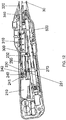
FIG. 1 is a perspective view from a side of an exemplary embodiment of an electric stapler according to the invention; -
FIG. 2 is a fragmentary side elevational view of the stapler ofFIG. 1 with a right half of a handle body and with a proximal backbone plate removed; -
FIG. 3 is an exploded, perspective view of an anvil control assembly of the stapler ofFIG. 1 ; -
FIG. 4 is an enlarged, fragmentary, exploded, perspective view of the anvil control assembly ofFIG. 3 ; -
FIG. 5 is a fragmentary, perspective view of a staple firing control assembly of the stapler ofFIG. 1 from a rear side thereof; -
FIG. 6 is an exploded, perspective view of the staple firing control assembly of the stapler ofFIG. 1 ; -
FIG. 7 is an enlarged, fragmentary, exploded, perspective view of the staple firing control assembly ofFIG. 6 ; -
FIG. 8 is a fragmentary, horizontally cross-sectional view of the anvil control assembly from below the handle body portion of the stapler ofFIG. 1 ; -
FIG. 9 is a fragmentary, enlarged, horizontally cross-sectional view from below a proximal portion of the anvil control assemblyFIG. 8 ; -
FIG. 10 is a fragmentary, enlarged, horizontally cross-sectional view from below an intermediate portion of the anvil control assembly ofFIG. 8 ; -
FIG. 11 is a fragmentary, enlarged, horizontally cross-sectional view from below a distal portion of the anvil control assembly ofFIG. 8 ; -
FIG. 12 is a fragmentary, vertically cross-sectional view from a right side of a handle body portion of the stapler ofFIG. 1 ; -
FIG. 13 is a fragmentary, enlarged, vertically cross-sectional view from the right side of a proximal handle body portion of the stapler ofFIG. 12 ; -
FIG. 14 is a fragmentary, enlarged, vertically cross-sectional view from the right side of an intermediate handle body portion of the stapler ofFIG. 12 ; -
FIG. 15 is a fragmentary, further enlarged, vertically cross-sectional view from the right side of the intermediate handle body portion of the stapler ofFIG. 14 ; -
FIG. 16 is a fragmentary, enlarged, vertically cross-sectional view from the right side of a distal handle body portion of the stapler ofFIG. 12 ; -
FIG. 17 is a perspective view of a portion of an anvil of the stapler ofFIG. 1 ; -
FIG. 18 is a fragmentary, cross-sectional view of a removable stapling assembly including the anvil, a stapler cartridge, a force switch, and a removable cartridge connecting assembly of the stapler ofFIG. 1 ; -
FIG. 19 is a fragmentary, horizontally cross-sectional view of the anvil control assembly from above the handle body portion of the stapler ofFIG. 1 with the anvil rod in a fully extended position; -
FIG. 20 is a fragmentary, side elevational view of the handle body portion of the stapler ofFIG. 1 from a left side of the handle body portion with the left handle body and the circuit board removed and with the anvil rod in a fully extended position; -
FIG. 21 is a fragmentary, side elevational view of the handle body portion of the stapler ofFIG. 20 with the anvil rod in a 1-cm anvil closure position; -
FIG. 22 is a fragmentary, horizontally cross-sectional view of the anvil control assembly from above the handle body portion of the stapler ofFIG. 1 with the anvil rod in a safe staple firing position; -
FIG. 23 is a fragmentary, horizontally cross-sectional view of the anvil control assembly from above the handle body portion of the stapler ofFIG. 1 with the anvil rod in a fully retracted position; -
FIG. 24 is a fragmentary, horizontally cross-sectional view of the firing control assembly from above the handle body portion of the stapler ofFIG. 1 ; -
FIG. 25 is a fragmentary, enlarged, horizontally cross-sectional view from above a proximal portion of the firing control assembly ofFIG. 24 ; -
FIG. 26 is a fragmentary, enlarged, horizontally cross-sectional view from above an intermediate portion of the firing control assembly ofFIG. 24 ; -
FIG. 27 is a fragmentary, enlarged, horizontally cross-sectional view from above a distal portion of the firing control assembly ofFIG. 24 ; -
FIGS. 28 and 29 are shaded, fragmentary, enlarged, partially transparent perspective views of a staple cartridge removal assembly of the stapler ofFIG. 1 ; -
FIG. 30 is a schematic circuit diagram of an exemplary encryption circuit for interchangeable parts of the medical device according to the invention; -
FIG. 31 is a bar graph illustrating a speed that a pinion moves a rack shown inFIG. 32 for various loads; -
FIG. 32 is a fragmentary, perspective view of a simplified, exemplary portion of a gear train according to the present invention between a gear box and a rack; -
FIG. 33 is a fragmentary, vertically longitudinal, cross-sectional view of a distal end of an articulating portion of an exemplary embodiment of an end effector with the inner tube, the pushrod-blade support, the anvil, the closure ring, and the near half of the staple sled removed; -
FIG. 34 is a schematic circuit diagram of an exemplary switching assembly for a power supply according to the invention; -
FIG. 35 is a schematic circuit diagram of an exemplary switching assembly for forward and reverse control of a motor according to the invention; and -
FIG. 36 is a schematic circuit diagram of another exemplary switching assembly for the power supply and the forward and reverse control of the motor according to the invention. - Aspects of the invention are disclosed in the following description and related drawings directed to specific embodiments of the invention. Alternate embodiments may be devised without departing from the spirit or the scope of the invention. Additionally, well-known elements of exemplary embodiments of the invention will not be described in detail or will be omitted so as not to obscure the relevant details of the invention.
- Before the present invention is disclosed and described, it is to be understood that the terminology used herein is for the purpose of describing particular embodiments only and is not intended to be limiting. It must be noted that, as used in the specification and the appended claims, the singular forms "a," "an," and "the" include plural references unless the context clearly dictates otherwise.
- While the specification concludes with claims defining the features of the invention that are regarded as novel, it is believed that the invention will be better understood from a consideration of the following description in conjunction with the drawing figures, in which like reference numerals are carried forward. The figures of the drawings are not drawn to scale. Further, it is noted that the figures have been created using a computer-aided design computer program. This program at times removes certain structural lines and/or surfaces when switching from a shaded or colored view to a wireframe view. Accordingly, the drawings should be treated as approximations and be used as illustrative of the features of the present invention.
- Referring now to the figures of the drawings in detail and first, particularly to
FIGS. 1 to 2 thereof, there is shown an exemplary embodiment of an electric surgicalcircular stapler 1. The present application applies the electrically powered handle to a circular surgical staple head for ease of understanding only. The invention is not limited to circular staplers and can be applied to any surgical stapling head, such as a linear stapling device, for example. - The
powered stapler 1 has ahandle body 10 containing three switches: an anvilopen switch 20, an anvilclose switch 21, and astaple firing switch 22. Each of these switches is electrically connected to a circuit board 500 (seeFIG. 12 ) having circuitry programmed to carry out the stapling functions of thestapler 1. Thecircuit board 500 is electrically connected to apower supply 600 contained within thehandle body 10. One exemplary embodiment utilizes 2 to 6 Lithium CR123 or CR2 cells as thepower supply 600. Other power supply embodiments are possible, such as rechargeable batteries or a power converter that is connected to an electric mains (in the latter embodiment, the stapler would not be self-powered or self-contained). As used herein, the terms self-powered or self-contained when used with regard to the electric power supply (600) are interchangeable and mean that the power supply is a complete and independent unit in and of itself and can operate under its own power without the use of external power sources. For example, a power supply having an electric cord that is plugged into an electric mains during use is not self-powered or self-contained. - Insulated conductive wires or conductor tracks on the
circuit board 500 connect all of the electronic parts of thestapler 1, such as an on/offswitch 12, atissue compression indicator 14, the anvil and firingswitches circuit board 500, and thepower supply 600, for example. But these wires and conductors are not shown in the figures of the drawings for ease of understanding and clarity. - The distal end of the
handle body 10 is connected to a proximal end of arigid anvil neck 30. Opposite this connection, at the distal end of theanvil neck 30, is acoupling device 40 for removably attaching astaple cartridge 50 and ananvil 60 thereto. Alternatively, thestaple cartridge 50 can be non-removable in a single-use configuration of thestapler 1. These connections will be described in further detail below. -
FIG. 2 shows thehandle body 10 with theright half 13 of thehandle body 10 and thecircuit board 500 removed. As will be discussed below, aproximal backbone plate 70 is also removed from the view ofFIG. 2 to allow viewing of the internal components inside thehandle body 10 from the right side thereof. What can be seen from the view ofFIG. 2 is that there exist two internal component axes within thehandle body 10. A first of these axes is thestaple control axis 80, which is relatively horizontal in the view ofFIG. 2 . Thestaple control axis 80 is the centerline on which lie the components for controlling staple actuation. The second of these axes is theanvil control axis 90 and is disposed at an angle to thestaple control axis 80. Theanvil control axis 90 is the centerline on which lie the components for controlling anvil actuation. It is this separation ofaxes electric stapler 1 to be powered using ahandle body 10 that is small enough to fit in a physician's hand and that does not take up so much space that the physician becomes restricted from movement in all necessary directions and orientations. - Shown inside the
handle body 10 is the on/off switch 12 (e.g., a grenade pin) for controlling power (e.g., battery power) to all of the electrical components and thetissue compression indicator 14. Thetissue compression indicator 14 indicates to the physician that the tissue being compressed between theanvil 60 and thestaple cartridge 50 has or has not been compressed with greater than a pre-set compressive force, which will be described in further detail below. Thisindicator 14 is associated with aforce switch 400 that has been described in co-pendingU.S. Patent Provisional Application Serial No. 60/801,989 filed May 19, 2006 - The components along the
anvil control axis 90 make up theanvil control assembly 100. Ananvil control frame 110 is aligned along theanvil control axis 90 to house and/or fix various part of theanvil control assembly 100 thereto. Theanvil control frame 110 has aproximal mount 112, anintermediate mount 114, and adistal mount 116. Each of thesemounts 112, 114,116 can be attached to or integral with thecontrol frame 110. In the exemplary embodiment, for ease of manufacturing, theproximal mount 112 has two halves and is separate from theframe 110 and theintermediate mount 114 is separate from theframe 110. - At the proximal end of the
anvil control assembly 100 is ananvil motor 120. Theanvil motor 120 includes the drive motor and any gearbox that would be needed to convert the native motor revolution speed to a desired output axle revolution speed. In the present case, the drive motor has a native speed of approximately 10,000 rpm and the gearbox converts the speed down to between approximately 50 and 70 rpm at anaxle 122 extending out from a distal end of theanvil motor 120. Theanvil motor 120 is secured both longitudinally and rotationally inside theproximal mount 112. - A motor-
shaft coupler 130 is rotationally fixed to theaxle 122 so that rotation of theaxle 122 translates into a corresponding rotation of themotor coupler 130. - Positioned distal of the
coupler 130 is arotating nut assembly 140. Thenut assembly 140 is, in this embodiment, a two part device having aproximal nut half 141 and adistal nut half 142 rotationally and longitudinally fixed to theproximal nut half 141. It is noted that thesenut halves nut assembly 140 is rotationally fixed to the distal end of thecoupler 130. Longitudinal and rotational support throughout the length of these two connected parts is assisted by the intermediate 114 and distal 116 mounts. - A proximal nut bushing 150 (see
FIG. 3 ) is interposed between theintermediate mount 114 and theproximal nut half 141 and adistal nut bushing 160 is interposed between thedistal mount 116 and thedistal nut half 142 to have these parts spin efficiently and substantially without friction within thehandle body 10 and theanvil control frame 110. Thebushings rotating nut assembly 140 and thecoupler 130, athrust washer 170 is disposed between theproximal bushing 150 and theproximal nut half 141. - Rotation of the
coupler 130 andnut assembly 140 is used to advance or retract a threadedrod 180, which is the mechanism through which theanvil 60 is extended or retracted. The threadedrod 180 is shown in further detail in the exploded view ofFIGS. 3 to 4 and is described in further detail below. Arod support 190 is attached to a distal end of theanvil control frame 110 for extending the supporting surfaces inside thenut assembly 140 that keep therod 180 aligned along theanvil control axis 90. Therod support 190 has a smooth interior shape corresponding to an external shape of the portion of therod 180 that passes therethrough. This mating of shapes allows therod 180 to move proximally and distally through thesupport 190 substantially without friction. To improve frictionless movement of therod 180 through thesupport 190, in the exemplary embodiment, acylindrical rod bushing 192 is disposed between thesupport 190 and therod 180. Therod bushing 192 is not visible inFIG. 2 because it rests inside thesupport 190. However, therod bushing 192 is visible in the exploded view ofFIGS. 3 to 4 . With therod bushing 192 in place, the internal shape of thesupport 190 corresponds to the external shape of therod bushing 192 and the internal shape of therod bushing 192 corresponds to the external shape of the portion of therod 180 that passes therethrough. Therod bushing 192 can be, for example, of metal such as bronze or a polymer such as nylon. - The components along the
staple control axis 80 form thestaple control assembly 200. Thestaple control assembly 200 is illustrated inFIG. 5 viewed from a proximal upper and side perspective. The proximal end of thestaple control assembly 200 includes astapling motor 210. The staplingmotor 210 includes the drive motor and any gearbox that would be needed to convert the native motor revolution speed to a desired revolution speed. In the present case, the drive motor has a native speed of approximately 20,000 rpm and the gearbox converts the speed to approximately 200 rpm at anoutput axle 212 at the distal end of the gearbox. Theaxle 212 cannot be seen in the view ofFIG. 5 but can be seen in the exploded view ofFIGS. 6 to 7 . - The stapling
motor 210 is rotationally and longitudinally fixed to amotor mount 220. Distal of themotor mount 220 is anintermediate coupling mount 230. Thiscoupling mount 230 has adistal plate 232 that is shown, for example inFIG. 6 . Thedistal plate 232 is removable from thecoupling mount 230 so that arotating screw 250 can be held therebetween. It is thisrotating screw 250 that acts as the drive for ejecting the staples out of thestaple cartridge 50. The efficiency in transferring the rotational movement ofaxle 212 to therotating screw 250 is a factor that can substantially decrease the ability of thestapler 1 to deliver the necessary staple ejection longitudinal force of up to 250 pounds. Thus, an exemplary embodiment of thescrew 250 has an acme profile thread. - There are two exemplary ways described herein for efficiently coupling the rotation of the
axle 212 to thescrew 250. First, the staplingmotor 210 can be housed "loosely" within a chamber defined by thehandle body 10 so that it is rotationally stable but has play to move radially and so that it is longitudinally stable but has play to move. In such a configuration, the staplingmotor 210 will "find its own center" to align the axis of the axle212 to the axis of thescrew 250, which, in the exemplary embodiment, is also thestaple control axis 80. - A second exemplary embodiment for aligning the
axle 212 and thescrew 250 is illustrated inFIGS. 1 to 5 , for example. In this embodiment, a proximal end of aflexible coupling 240 is fixed (both rotationally and longitudinally) to theaxle 212. This connection is formed by fitting the distal end of theaxle 212 inside aproximal bore 241 of theflexible coupling 240. SeeFIG. 12 . Theaxle 212 is, then, secured therein with aproximal setscrew 213. Thescrew 250 has aproximal extension 251 that fits inside adistal bore 242 of theflexible coupling 240 and is secured therein by adistal setscrew 252. It is noted that the figures of the drawings show theflexible coupling 240 with ridges in the middle portion thereof. In an exemplary embodiment of thecoupling 240, the part is of aluminum or molded plastic and has a spiral or helixed cut-out around the circumference of the center portion thereof. In such a configuration, one end of thecoupling 240 can move in any radial direction (360 degrees) with respect to the other end (as in a gimbal), thus providing the desired flex to efficiently align the central axes of theaxle 212 and thescrew 250. - The
proximal extension 251 of thescrew 250 is substantially smaller in diameter than the diameter of thebore 231 that exists in and through theintermediate coupling mount 230. This bore 231 has two increasing steps in diameter on the distal side thereof. The first increasing step in diameter is sized to fit a proximalradius screw bushing 260, which is formed of a material that is softer than theintermediate coupling mount 230. The proximalradius screw bushing 260 only keeps thescrew 250 axially aligned and does not absorb or transmit any of the longitudinal thrust. The second increasing step in diameter is sized to fit aproximal thrust bearing 270 for thescrew 250. In an exemplary embodiment of thethrust bearing 270, proximal and distal plates sandwich a bearing ball retainer plate and bearing balls therebetween. This thrust bearing 270 absorbs all of the longitudinal thrust that is imparted towards theaxle 212 while the up to 250 pounds of longitudinal force is being applied to eject the staples in thestaple cartridge 50. Theproximal extension 251 of thescrew 250 has different sized diameters for each of the interiors of thescrew bushing 260 and thethrust bearing 270. Themotor mount 220 and thecoupling mount 230, therefore, form the two devices that hold theflexible coupling 240 therebetween. - The
rotating screw 250 is held inside thedistal plate 232 with a distalradius screw bushing 280 similar to the proximalradius screw bushing 260. Thus, thescrew 250 rotates freely within thedistal plate 232. To translate the rotation of thescrew 250 into a linear distal movement, thescrew 250 is threaded within a movingnut 290. Movement of thenut 290 is limited to the amount of movement that is needed for complete actuation of the staples; in other words, thenut 290 only needs to move through a distance sufficient to form closed staples between thestaple cartridge 50 and theanvil 60 and to extend the cutting blade, if any, within thestaple cartridge 50, and then retract the same. When thenut 290 is in the proximal-most position (see, e.g.,FIG. 12 ), the staples are at rest and ready to be fired. When thenut 290 is in the distal-most position, the staples are stapled through and around the tissue interposed between thestaple cartridge 50 and the anvil, and the knife, if any, is passed entirely through the tissue to be cut. The distal-most position of thenut 290 is limited by the location of thedistal plate 232. Thus, the longitudinal length of the threads of thescrew 250 and the location of thedistal plate 232 limit the distal movement of thenut 290. - Frictional losses between the
screw 250 and thenut 290 contribute to a significant reduction in the total pounds of force that can be transmitted to thestaple cartridge 50 through thecartridge plunger 320. Therefore, it is desirable to select the materials of thescrew 250 and thenut 290 and the pitch of the threads of thescrew 250 in an optimized way. It has been found that use of a low-friction polymer for manufacturing thenut 290 will decrease the friction enough to transmit the approximately 250 pounds of longitudinal force to the distal end of thecartridge plunger 320 -- the amount of force that is needed to effectively deploy the staples. Two particular exemplary materials provide the desired characteristics and are referred to in the art as DELRIN® AF Blend Acetal (a thermoplastic material combining TEFLON® fibers uniformly dispersed in DELRIN® acetal resin) and RULON® (a compounded form of TFE fluorocarbon) or other similar low-friction polymers. - A
nut coupling bracket 300 is longitudinally fixed to thenut 290 so that it moves along with thenut 290. Thenut coupling bracket 300 provides support for the relatively soft, lubricious nut material. In the exemplary embodiment shown, thebracket 300 has an interior cavity having a shape corresponding to the exterior shape of thenut 290. Thus, thenut 290 fits snugly into thecoupling bracket 300 and movement of thenut 290 translates into a corresponding movement of thenut coupling bracket 300. The shape of thenut coupling bracket 300 is, in the exemplary embodiment, dictated by the components surrounding it and by the longitudinal forces that it has to bear. For example, there is aninterior cavity 302 distal of thenut 290 that is shaped to receive thedistal plate 232 therein. Thenut coupling bracket 300 also has adistal housing 304 for receiving therein astiffening rod 310. The stiffeningrod 310 increases the longitudinal support and forms a portion of the connection between thenut 290 and a cartridge plunger 320 (see, i.e.,FIG. 5 ), which is the last moving link between elements in thehandle body 10 and thestaple cartridge 50. Afiring bracket 330, disposed between the distal end of thenut coupling bracket 300 and thestiffening rod 310, strengthens the connection between thenut coupling bracket 300 and therod 310. - Various components of the
stapler 1 are connected to one another to form a backbone or spine. This backbone is a frame providing multi-directional stability and is made up of four primary parts (in order from proximal to distal): theanvil control frame 110, the proximal backbone plate 70 (shown inFIGS. 3 to 4 and 6 to 7 ), adistal backbone plate 340, and theanvil neck 30. Each of these four parts is longitudinally and rotationally fixed to one another in this order and forms the skeleton on which the remainder of the handle components is attached in some way. Lateral support to the components is provided by contours on the inside surfaces of thehandle body 10, which in an exemplary embodiment is formed of two halves, aleft half 11 and aright half 13. Alternatively, support could be single frame, stamped, or incorporated into the handle halves 11, 13. - Functionality of the
anvil control assembly 100 is described with regard toFIGS. 17 to 27 . To carry out a stapling procedure with thestapler 1, theanvil 60 is removed entirely from thestapler 1 as shown inFIG. 17 . The anvilopen switch 20 is depressed to extend the distal end of thetrocar tip 410 housed within the staple cartridge and which is longitudinally fixedly connected to thescrew 250. The point of thetrocar tip 410 can, now, be passed through or punctured through tissue that is to be stapled. The user can, at this point, replace theanvil 60 onto thetrocar tip 410 from the opposite side of the tissue (seeFIG. 18 ) and, thereby, lock theanvil 60 thereon. The anvil closedswitch 22 can be actuated to begin closing theanvil 60 against thestaple cartridge 50 and pinch the tissue therebetween within an anvil-cartridge gap 62. - To describe how the trocar tip controlling movement of the
anvil 60 occurs, reference is made toFIGS. 8 to 10, 14 to 15, and 18 . As shown in dashed lines inFIG. 15 , a rod-guidingpin 143 is positioned within thecentral bore 144 of thedistal nut half 142. As the threadedrod 180 is screwed into therotating nut pin 143 catches the proximal end of thethread 182 to surround thepin 143 therein. Thus, rotation of thenut 140 with thepin 143 inside thethread 182 will cause proximal or distal movement of therod 180, depending on the direction of nut rotation. Thethread 182 has a variable pitch, as shown inFIGS. 14 to 15 , to move theanvil 60 at different longitudinal speeds. When thepin 143 is inside the longer (lower) pitchedthread portion 183, theanvil 60 moves longitudinally faster. In comparison, when thepin 143 is inside the shorter (higher) pitchedthread portion 184, theanvil 60 moves longitudinally slower. It is noted that thepin 143 is the only portion contacting thethread 182 when in the longer pitchedthread portion 183. Thus, thepin 143 is exposed to the entire longitudinal force that is acting on therod 180 at this point in time. Thepin 143 is strong enough to bear such forces but may not be sufficient to withstand all longitudinal force that could occur withanvil 60 closure about interposed tissue. - As shown in
FIG. 14 , therod 180 is provided with a shorterpitched thread portion 184 to engage in a correspondinginternal thread 145 at the proximal end of thecentral bore 144 of theproximal nut half 141. When the shorter pitchedthread portion 184 engages theinternal thread 145, the entire transverse surface of thethread portion 184 contacts theinternal thread 145. This surface contact is much larger than the contact between thepin 143 and any portion of thethread 182 and, therefore, can withstand all the longitudinal force that occurs with respect toanvil 60 closure, especially when theanvil 60 is closing about tissue during the staple firing state. For example, in the exemplary embodiment, thepin 143 bears up to approximately 30 to 50 pounds of longitudinal force. This is compared to the threads, which can hold up to 400 pounds of longitudinal force-an almost 10-to-1 difference. - An alternative exemplary embodiment of
anvil control assembly 100 can entirely remove the complex threading of therod 180. In such a case, therod 180 has a single thread pitch and theanvil motor 120 is driven (through corresponding programming in the circuit board 500) at different speeds dependent upon the longitudinal position of the single-thread rod 180. - In any embodiment for driving the motors 120,210, the control programming can take many forms. In one exemplary embodiment, the microcontroller on the battery powered
circuit board 500 can apply pulse modulation (e.g., pulse-width, pulse-frequency) to drive either or both of the motors. Further, because thestapler 1 is a device that has a low duty cycle, or is a one-use device, components can be driven to exceed acceptable manufacturers' specifications. For example, a gear box can be torqued beyond its specified rating. Also, a drive motor, for example, a 6 volt motor, can be overpowered, for example, with 12 volts. - Closure of the
anvil 60 from an extended position to a position in which the tissue is not compressed or is just slightly compressed can occur rapidly without causing damage to the interposed tissue. Thus, the longer-pitchedthread portion 183 allows the user to quickly close theanvil 60 to the tissue in a tissue pre-compressing state. Thereafter, it is desirable to compress the tissue slowly so that the user has control to avoid over-compression of the tissue. As such, the shorter pitchedthread portion 184 is used over this latter range of movement and provides the user with a greater degree of control. During such compression, theforce switch 400 seen inFIG. 18 and described in co-pendingU.S. Patent Provisional Application Serial No. 60/801,989 can be used to indicate to the user through the tissue compression indicator 14 (and/or to the control circuitry of the circuit board 500) that the tissue is being compressed with a force that is greater than the pre-load of thespring 420 inside theforce switch 400. It is noted thatFIG. 18 illustrates theforce switch 400 embodiment in the normally-open configuration described as the first exemplary embodiment ofU.S. Patent Provisional Application Serial No. 60/801,989 . A strain gauge can also be used for measuring tissue compression. -
FIGS. 19 to 23 illustrate movement of therod 180 from an anvil-extended position (seeFIGS. 19 to 20 ), to a 1-cm-closure-distance position (seeFIG. 21 ), to a staple-fire-ready position (seeFIG. 22 ), and, finally, to an anvil fully closed position (seeFIG. 23 ). Movement of therod 180 is controlled electrically (via the circuit board 500) by contact between a portion of acam surface actuator 185 on therod 180 and actuating levers or buttons of a series of micro-switches positioned in thehandle body 10. - A rod-fully-extended switch 610 (see
FIG. 19 ) is positioned distal in thehandle body 10 to have theactuator 185 compress the activation lever of the rod-fully-extendedswitch 610 when the rod 180 (and, thereby, the anvil 60) is in the fully extended position. A 1-cm switch 612 is positioned in an intermediate position within the handle body 10 (seeFIGS. 20 to 21 ) to prevent a 1-cmcam surface portion 186 of therod 180 from pressing the activation button of the 1-cm switch 612 when the rod 180 (and, thereby, the anvil 60) is within 1 cm of the fully closed position. After passing the 1-cm closure distance, as shown inFIG. 22 , thecam surface actuator 185 engages a staple-fire-ready switch 614. The lower end of theactuator 185 as viewed inFIGS. 22 to 23 has a bevel on both the forward and rear sides with respect to the button of the staple-fire-ready switch 614 and the distance between the portion on the two bevels that actuates the button (or, only the flat portion thereof) corresponds to the acceptable staple forming range (i.e., safe firing length) of the staples in thestaple cartridge 50. Thus, when the button of the staple-fire-ready switch 614 is depressed for the first time, the distance between theanvil 60 and thestaple cartridge 50 is at the longest range for successfully firing and closing the staples. While the button is depressed, theseparation distance 62 of the anvil 60 (seeFIG. 18 ) remains within a safe staple-firing range. However, when the button of the staple-fire-ready switch 614 is no longer depressed - because theactuator 185 is positioned proximally of the button, then staples will not fire because the distance is too short for therapeutic stapling.FIG. 23 show therod 180 in the proximal-most position, which is indicated by the top end of theactuator 185 closing the lever of a rod fully-retractedswitch 616. When thisswitch 616 is actuated, the programming in thecircuit board 500 prevents themotor 120 from turning in a rod-retraction direction; in other words, it is a stop switch for retracting therod 180 in the proximal direction. - It is noted that
FIGS. 2 to 3, 11 to 12, and 16 illustrate the distal end of therod 180 not being connected to another device at its distal end (which would then contact the proximal end of the force switch 400). The connection band or bands between the distal end of therod 180 and the proximal end of theforce switch 400 are not shown in the drawings only for clarity purposes. In an exemplary embodiment, the pull-bands are flat and flexible to traverse the curved underside of thecartridge plunger 320 through theanvil neck 30 and up to the proximal end of theforce switch 400. Of course, if theforce switch 400 is not present, the bands would be connected to the proximal end of thetrocar tip 410 that releasably connects to the proximal end of theanvil 60. - Functionality of the
staple control assembly 200 is described with regard toFIGS. 12 to 16and 24 to 27 , in particular, toFIG. 24 . The staplingmotor 210 is held between amotor bearing 222 and amotor shaft cover 224. Theaxle 212 of the staplingmotor 210 is rotationally connected to the proximal end of theflexible coupling 240 and the distal end of theflexible coupling 240 is rotationally connected to the proximal end of thescrew 250, which rotates onbearings intermediate coupling mount 230 and thedistal plate 232. Thelongitudinally translating nut 290 is threaded onto thescrew 250 between thecoupling mount 230 and thedistal plate 232. Therefore, rotation of theaxle 212 translates into a corresponding rotation of thescrew 250. - The
nut coupling bracket 300 is longitudinally fixed to thenut 290 and to thestiffening rod 310 and thefiring bracket 330. Thefiring bracket 330 is longitudinally fixed to thecartridge plunger 320, which extends (through a non-illustrated staple driver) up to the staple cartridge 50 (or to the staples). With such a connection, longitudinal movement of thenut 290 translates into a corresponding longitudinal movement of thecartridge plunger 320. Accordingly, when thestaple firing switch 22 is activated, the staplingmotor 210 is caused to rotate a sufficient number of times so that the staples are completely fired from the staple cartridge 50 (and the cutting blade, if present, is extended to completely cut the tissue between theanvil 60 and the staple cartridge 50). Programming in the circuitry, as described below, then causes thecartridge plunger 320 to retract after firing and remove any portion of the staple firing parts and/or the blade within thestaple cartridge 50 from the anvil-cartridge gap 62. - Control of this stapling movement, again, occurs through micro-switches connected to the
circuit board 500 through electrical connections, such as wires. A first of these control switches, theproximal staple switch 618, controls retraction of thestaple control assembly 200 and defines the proximal-most position of thisassembly 200. To actuate this switch, anactuation plate 306 is attached, in an adjustable manner, to a side of thenut coupling bracket 300. See, e.g.,FIGS. 6 and24 . As such, when thenut 290 moves proximally to cause theplate 306 on thenut coupling bracket 300 to activate theproximal staple switch 618, power to thestapling motor 210 is removed to stop further proximally directed movement of thestaple control assembly 200. - A second of the switches for controlling movement of the
staple control assembly 200 is located opposite a distal transverse surface of the stiffeningrod 310. See, e.g.FIG. 27 . At this surface is disposed a longitudinallyadjustable cam member 312 that contacts adistal staple switch 620. In an exemplary embodiment, thecam member 312 is a screw that is threaded into a distal bore of the stiffeningrod 310. Accordingly, when thenut 290 moves distally to cause thecam member 312 of the stiffeningrod 310 to activate thedistal staple switch 620, power to thestapling motor 210 is removed to stop further distally directed movement of thestaple control assembly 200. -
FIGS. 28 and 29 illustrate a removable connection assembly to permit replacement of adifferent staple cartridge 60 on the distal end of theanvil 30. - The proximal-most chamber of the
handle body 10 defines a cavity for holding therein apower supply 600. Thispower supply 600 is connected through thecircuit board 500 to themotors stapler 1. - The electronic components of the
stapler 1 have been described in general with respect to control through thecircuit board 500. Theelectric stapler 1 includes, as set forth above in an exemplary embodiment, two drivemotors pushbuttons limit switches intermediary locations motors motors - A software program is required to provide control instructions to such a processor. Once fully developed, the program can be written to the processor and stored indefinitely. Such a system makes changes to the control algorithm relatively simple; changes to the software that are uploaded to the processor adjust the control and user interface without changing the wiring or mechanical layout of the device.
- For a disposable device, a power-on event is a one time occurrence. In this case, the power-on can be accomplished by pulling a tab or a release that is permanently removed from the device. The removal enables battery contact, thus powering on the device.
- In any embodiment of the device, when the device is powered on, the control program begins to execute and, prior to enabling the device for use, goes through a routine that ensures awareness of actual positions of the extend/retract and firing sub-assemblies, referred to as a homing routine. The homing routine may be executed at the manufacturer prior to shipping to the user. In such a case, the homing routine is performed, the positions of the assemblies are set, and the device is shipped to the user in a ready-to-use condition. Upon power-up, the device verifies its positions and is ready to use.
- Visual indicators (e.g., LEDs) are used to provide feedback to the user. In the case of the pushbutton switches 20, 21, 22, they can be lit (or backlit) when active and unlit when not active. The indicators can blink to convey additional information to the user. In the case of a delayed response after a button press, a given light can blink at an ever-increasing rate as the response becomes imminent, for example. The indicators can also light with different colors to indicate various states.
- Cams are used in various locations at the
stapler 1 to activate limit switches that provide position information to the processor. By using linear cams of various lengths, position ranges can be set. Alternatively, encoders can be used instead of limit switches (absolute and incremental positioning). Limit switches are binary: off or on. Instead of binary input for position information, encoders (such as optical encoders) can be used to provide position information. Another way to provide position feedback includes mounting pulse generators on the end of the motors that drive the sub-assemblies. By counting pulses, and by knowing the ratio of motor turns to linear travel, absolute position can be derived. - Use of a processor creates the ability to store data. For example, vital, pre-loaded information, such as the device serial number and software revision can be stored. Memory can also be used to record data while the
stapler 1 is in use. Every button press, every limit switch transition, every aborted fire, every completed fire, etc., can be stored for later retrieval and diagnosis. Data can be retrieved through a programming port or wirelessly. In an exemplary embodiment, the device can be put into diagnostic mode through a series of button presses. In this diagnostic mode, a technician can query thestapler 1 for certain data or to transmit/output certain data. Response from thestapler 1 to such a query can be in the form of blinking LEDs, or, in the case of a device with a display, visual character data, or can be electronic data. As set forth above, a strain gauge can be used for analog output and to provide an acceptable strain band. Alternatively, addition of a second spring and support components can set this band mechanically. - An exemplary control algorithm for a
single fire stapler 1 can include the following steps: - ∘ Power on.
- ∘ Verify home position and go to home position, if necessary/desired.
- ∘ Enable extend/retract buttons (lit) and disable (unlit) staple fire button.
- ∘ Enable staple fire button only after full extension (anvil removal) and subsequent retraction with extend/retract buttons remaining enabled.
- ∘ Upon actuation of staple fire button, retract anvil until force switch is activated.
- ∘ Begin countdown by blinking fire button LED and increase blink rate as firing cycle becomes imminent. Continue monitoring of force switch and retract anvil so that force switch remains activated.
- ∘ During staple fire cycle, any button press aborts staple fire routine.
- ∘ If abort occurs before staple firing motor is activated, firing cycle stops, anvil is extended to home position, and staple fire button remains active and ready for a re-fire.
- ∘ Alternatively, if the abort occurs during movement of firing motor, firing cycle stops, firing motor is retracted, anvil is returned to home position, and firing button is rendered inactive. Accordingly, stapler (or that staple cartridge) cannot be used.
- ∘ After countdown to fire is complete, staple range limit switch is queried for position. If staple range limit switch is activated -- meaning that anvil is within an acceptable staple firing range -- then staple firing motor is activated and firing cycle proceeds. If staple range limit switch is not activated, then firing cycle is aborted, anvil is returned to home position, and staple firing button remains active ready for a re-fire attempt.
- ∘ After a completed staple firing, anvil remains in closed position and only the extend button remains active. Once anvil is extended to at least the home position, both extend and retract buttons are made active. Staple fire button remains inactive after a completed staple firing.
- In a surgical procedure, the stapler is a one-way device. In the test mode, however, the test user needs to have the ability to move the
trocar 410 andanvil 60 back and forth as desired. The power-on feature permits entry by the user into a manual mode for testing purposes. This test mode can be disengaged and the stapler reset to the use mode for packaging and shipment. - For packaging, it is desirable (but not necessary) to have the
anvil 60 be disposed at a distance from thestaple cartridge 50. Therefore, a homing sequence can be programmed to place theanvil 60 one centimeter (for example) away from thestaple cartridge 50 before powering down for packaging and shipment. - When the electric stapler is unpackaged and ready to be used for surgery, the user turns the stapler on (switch 12). Staples should not be allowed to fire at any time prior to being in a proper staple-firing position and a desired tissue compression state. Thus, the anvil/trocar extend/retract function is the only function that is enabled. In this state, the extend and retract
buttons staple firing switch 22 is not lit (i.e., disabled). - Before use inside the patient, the
trocar 410 is extended and theanvil 60 is removed. If the stapler is being used to anastomose a colon, for example, thetrocar 410 is retracted back into theanvil neck 30 and thestaple cartridge 50 andanvil neck 30 are inserted trans-anally into the colon to a downstream side of the dissection. Theanvil 60, in contrast, is inserted through an upstream laparoscopic incision and placed at the upstream side of the dissection. Theanvil 60 is attached to thetrocar 410 and the two parts are retracted towards thestaple cartridge 50 until a staple ready condition occurs. As set forth above, the anvil is moved to a distance that does not substantially compress and, specifically, does not desiccate, the tissue therebetween. At this point, staple firing can occur when desired. - The staple firing sequence is started by activating the
staple fire switch 22. Staple firing can be aborted anytime during the firing sequence, whether prior to movement (during the blanching cycle) or during movement (whether the staples have started to form or not). The software is programmed to begin a staple firing countdown sequence because it is understood that the tissue needs to be compressed and allowed to desiccate before staple firing should occur. Thus, after thestaple firing switch 22 is activated, theanvil 60 closes upon the interposed tissue and begins to compress the tissue. The staple firing sequence includes an optimal tissue compression (OTC) measurement and a feedback control mechanism that causes staples to be fired only when the compression is in a desired pressure range, referred to as the OTC range, and a sufficient time period has elapsed to allow fluid removal from the compressed tissue. The OTC range is known beforehand based upon known characteristics of the tissue that is to be compressed between theanvil 60 and the staple cartridge 50 (the force switch can be tuned for different tissue OTC ranges). It is theforce switch 400 that provides the OTC measurement and supplies the microprocessor with information indicating that the OTC for that particular tissue has been reached. The OTC state can be indicated to the user with an LED, for example. - When the firing sequence begins, the
staple fire switch 22 can be made to blink at a given rate and then proceed to blink faster and faster, for example, until firing occurs. If no abort is triggered during this wait time, the OTC state will remain for the preprogrammed desiccation duration and staple filing will occur after the countdown concludes. In the example of colon anastomosis with a circular stapler, stapling of the dissection occurs simultaneously with a cutting of tissue at the center of the dissection. This cutting guarantees a clear opening in the middle of the circular ring of staples sufficient to create an opening for normal colon behavior after the surgery is concluded. - As the liquid from the interposed compressed tissue is removed, the compressive force on the tissue naturally reduces. In some instances, this reduction can be outside the OTC range. Therefore, the program includes closed-loop anvil-compression control that is dependent upon continuous measurements provided by the
force switch 400. With this feedback, the compressed tissue is kept within the OTC range throughout the procedure and even after being desiccated. - During the staple firing cycle, any actuation of a control switch by the user can be programmed to abort the staple fire routine. If an abort occurs before the
staple firing motor 210 is activated, the firing cycle stops, theanvil 60 is extended to a home position, and thestaple fire switch 22 remains active and ready for a re-fire attempt, if desired. Alternatively, if the abort occurs during movement of thestaple firing motor 210, the firing cycle stops and thestaple firing motor 210 is caused to extend theanvil 60 to its home position. At this point, thestaple firing switch 22 is rendered inactive. Accordingly, the stapler (or that particular staple cartridge) can no longer be used (unless the staple cartridge is replaced). - It is noted that before a staple firing can occur, a staple range limit switch is queried for relative position of the
staple cartridge 50 andanvil 60. If the staple range limit switch is activated -- meaning thatanvil 60 is within an acceptable staple firing range -- then thestaple firing motor 210 can be made active and the firing cycle can be allowed to proceed If the staple range limit switch is not activated, then the firing cycle is aborted, theanvil 60 is returned to the home position, and thestaple firing switch 22 remains active and ready for a re-fire attempt. - Powering (also referred to as actuating, powering, controlling, or activating) of the motor and/or the drive train of any portion of the end effector (e.g., anvil or stapler/cutter) is described herein. It is to be understood that such powering need not be limited to a single press of an actuation button by the user nor is the powering of a motor limited to a single energizing of the motor by the power supply. Control of any motor in the device can require the user to press an actuation button a number of times, for example, a first time to actuate a portion of the end effector for a first third of movement, a second time for a second third of movement, and a third time for a last third of movement. More specifically for a surgical stapler, a first exemplary actuation can move the staple sled or blade past the lock-out, a second exemplary actuation can move the part up to the tissue, and a third exemplary actuation can move the sled past all staples to the end of the staple cartridge. Similarly, powering of a motor need not be constant, for example, where the motor is energized constantly from the time that the blade begins movement until it reaches the end point of its movement. Instead, the motor can be operated in a pulsed mode, a first example of which includes periodically switching on and off the power supplied by the power supply to the motor during actuation of an end effector function. More specifically for a stapler, the motor can be pulsed ten times/second as the staple/cutter moves from its proximal/start position to its distal-most position. This pulsing can be directly controlled or controlled by microprocessor, either of which can have an adjustable pulse rate. Alternatively, or additionally, the motor can be operated with a pulse modulation (pulse-width or pulse-frequency), with pulses occurring at very short time periods (e.g., tenths, hundredths, thousandths, or millionths of a second). Accordingly, when the power supply, the motor, and/or the drive train are described herein as being powered, any of these and other possible modes of operation are envisioned and included.
- After a completed staple firing, the
anvil 60 remains in the closed position and only the extendswitch 20 remains active (all other switches are deactivated). Once theanvil 60 is extended to at least the home position, both the extend and retractswitches retraction switch 21 does not permit closure of theanvil 60 past the home position. Thestaple fire switch 22 remains inactive after a completed staple firing. - As set forth above, the
anvil neck 30 houses alinear force switch 400 connected to thetrocar 410. Thisswitch 400 is calibrated to activate when a given tensile load is applied. The given load is set to correspond to a desired pressure that is to be applied to the particular tissue before stapling can occur. Interfacing thisswitch 400 with the processor can ensure that the firing of staples only occurs within the OTC range. - The following text is an exemplary embodiment of a program listing for carrying out the methods according to the invention as described herein. The text that follows is only submitted as exemplary and those of skill in the art can appreciate that programming the methods according to the invention can take many different forms to achieve the same functionality.
'Circular Stapler Program using the rev 3c board (cb280 chipset) V8.03 (CS-3c-080306.CUL) '8-3-06 'Modified program to abort with only fire button, added pbcount variable 'Added PWM ramping '7-28-06 'final tweaks - stan is now an integer etc. '7-17-06 This version written for the 3c board. '7-14 DEBUGGING VERSION 'Program written for 3c board using theCubloc 280 chipset 'Note: this program is a modified version of the ones noted below. All changes not related to the addition of the E/R limit switches 'apply. The programs below were written to deal with the "gray logic" of the 1 cm switch. This version uses 'a limit switch at either end of the extend/retract stage. 'V6.20 Final Version of Gray Logic program as used inprototype 0, serial number 100 'V6.05 'modified the extend tocm 1 and retract tocm 1 routines to make sure that when they are called that they move the motor until the cm 'switch is closed; ie: When the anvil is all the way out and the retract button is pressed, retract the anvil until the cm limit switch 'is closed regardless of whether the retract button is released before the cm switch is closed. Same change for when the anvil is 'extended from the 1 cm position. 'made changes to comments in the extend/retract routines ' 'V6.02 'added loop requiring the release of both buttons to exit jog routine, and a 1 second delay at the end of jog subroutine before 'going back to main routine 'reformatted datadump labels 'added variables for high and low speed pwm values 'added extend only capability at end of completed fire to prevent crushing stapled tissue 'NOT WORKING- REMOVED added checks To ensure 1 cm switch Is made when extending Or retracting from the 1 cm And fully extended positions respectively 'V6.01 'All prior versions were made for testing the program on the Cubloc development board. All outputs were pulled LOW. The actual device 'requires all the outputs to be pulled high (+5V). This version is set-up to run on the actual device. 'limited the values of the EEPROM data to 255 max 'added delays before changes in motor direction, made program run smoother 'removed pwmoff commands. They were not allowing the motors to stay on when changing subroutines (for some reason) 'V5.27 'added the recording of jog routine button presses 'added the recording of datadump requests 'V5.26 'added the recording of Extend/Retract button presses 'added serial number field in eeprom 'the datadump routine now keeps running total of data as it is read from eeprom 'V5.25 (circular-stapler-5-25.cul) 'added code to allow storage of data each power on cycle in eeprom 'V524 works well, no known bugs (circuiar-stapler-5-24-cul) ' 'KMS Medical LLC (c) 2006 'MAP
- 'P10
- Extend Button
- 'P11
- Retract Button
- 'P12
- Fire Button
- 'P13
- Extend Limit
- 'P14
- Retract Limit
- 'P15
- Fire Forward Limit
- 'P16
- Fire Back Limit
- 'P17
- cm Limit Switch
- 'P18
- Staple Range Limit Switch
- 'P19
- Force Switch
- 'P20
- Extend Button LED
- 'P21
- Retract Button LED
- 'P22
- Fire Button LED
- 'P23
- Force LED (blue)
- 'P24
- Not USED
- 'P25
- Not USED
- 'P26
- Not USED
- 'P27
- Not USED
- 'P28
- Not USED
- 'P29
- Staple Range LED (green)
 Const Device=cb280 'Cornfile Tech. Cubloc CB280 chipset
 Dim ver As String*7
 ver="3C-8.03" 'set software version here
 Dim extendbutton As Byte
 Dim retractbutton As Byte
 Dim firebutton As Byte
 Dim firstout As Byte
 Dim firstback As Byte
 Dim cmstatus As Byte'1cm limit switch status
 Dim srstatus As Byte 'staplerange limit switch status
 Dim x As Integer
 Dim powerons As Byte 'store in eeprom address 2
 Dim cycnumfires As Byte 'store in eeprom (powerons*5)
 Dim cycabortfires As Byte 'store in eeprom (powerons*5)+1
 Dim cycers As Byte 'store in eeprom, number of cycle extend/retract presses
 Dim cycjogs As Byte
 Dim arm As Byte
 Dim completefire As Byte
 Dim staplerangestatus As Byte
 Dim bail As Byte
 Dim ds As Integer 'eeprom data start location for individual cycle data writing
 Dim fast As Integer
 Dim slow As Integer
 Dim extendonly As Byte
 Dim extlimit As Byte
 Dim retlimit As Byte
 Dim speed As Integer
 Dim dracula As Byte
 'initalize outputs
 Out 20,0 'extend button LED
 Out 21,0 'retract button led
 Out 22,0 'fire button led
 Out 23,0 'force led
 Out 29,0 'staple range led
 'initialize variables
 firstout=0
 firstback=0
 completefire=0
 arm=0
 bail=0
 cycnumfires=0
 cycabortfires=0
 cycers=0
 cycjogs=0
 extendonly=0
 'CHANGE PWM VALUES HERE
 fast=60000 'highspeed pwm value
 slow=60000 'lowspeed pwm value
 speed=0
 Output 5 'turns on pwm output for PINCH
 Output 6 'turns on pwm output for FIRE
 'read totals from eeprom
 powerons=Eeread(2,1)
 Incr powerons 'increment total power on number
 If powerons>=255 Then powerons=255 'limit number of recorded powerons to an integer of one
 byte max
 Eewrite 2,powerons,1 'write total power on number to eeprom
 ds=powerons*5
 'JOG and DATADUMP Check
 'push any button within 2 (or so) seconds to go to jog routine
 'hold all three buttons on at startup to dump the data
 For x=1 To 50
        If Keyin(10,20)=0 And Keyin(11,20)=0 And Keyin(12,20)=0 Then
        datadump 'write all stored data to the debug screen
       Exit For
       Elseif Keyin(10,20)=0 Or Keyin(11,20)=0 Or Keyin(12,20)=0 Then 'either e/r button or
       the fire button pressed
       jog
       Exit For
       End If
       Delay 20
       Next
       '--------------------
       'HOMING SEQUENCES
       '--------------------
       cmstatus=Keyin(17,20) 'read the status of the 1cm limit switch
       If cmstatus=0 Then
       homeretract
       Elseif cmstatus=1 Then
       homeextend
       End If

       'check firebutton led status
       If firstout=1 And firstback=1 And arm=1 And completefire<>1 And cmstatus<>0 Then
               Out 22,1 'turn on fire button led
               Else
               Out 22,0 'turn off fire led
       End If
       'check for extend retract button press
       If extendbutton=0 And cmstatus=0 Then
               extend
       Elseif cmstatus=1 And extendbutton=0 Then
               extend
       End If
       If retractbutton=0 And cmstatus=0 Then 'And extendonly=0
               retract
       End If
       'check for firebutton press
       If firebutton=0 And firstout=1 And firstback=1 And arm=1 And completefire<>1 And
       cmstatus<>0 Then initialfire
       Loop 'keep looping til powerdown
       End 'End of program
       '******************************************************************
       'SUBROUTINES
       '
       '******************************************************************
 '------------------------------------------------------------------------
 'HOME: retract to cm switch=not pressed
 '------------------------------------------------------------------------
 Sub homeretract() 'retract until 1 cm switch is open
 'Debug "Homeretract",Cr
 'Delay 1000
 Pwm 0,slow,60000
 Do Until Keyin(17,20)=1 'retract until 1 cm switch is open
         Out 31,1 'ER motor reverse
 Loop
 Out 31,0' er motor off
 Out 21,0 'turn retract led Off
 Out 20,1 'turn extend led On
 Pwmoff 0 'turn pwm off
 End Sub
 '-----------------------------------------------------------------------
 'HOME: extend to cm switch=pressed
 '------------------------------------------------------------------------
 Sub homeextend() 'extend until 1 cm switch is closed
 'Debug "Homextend",Cr
 'Delay 1000
 Pwm 0,slow,60000
 If Keyin(17,20)=1 Then
         Do Until Keyin(17,20)=0 'now the 1 cm switch is pressed
                 Out 30,1 'ER motor forward DDD
         Loop
 End If
  Out 30,0'DDD
  Pwrnoff 0
  Delay 300
  homeretract 'once the switch is made, call homeretract
  End Sub
  '------------------------------------------------------------------------
 'Fire motor homing routine
 '------------------------------------------------------------------------
 Sub homefire()
 'Debug "Homefire",Cr
 'Delay 1000
 Pwm 1,slow,60000
 Do Until Keyin(16,20)=0 'retract firing stage until back switch is closed
         Out 33,1
 Loop
 Out 33,0
 Pwmoff 1
 End Sub
 '--------------------------------------------------------------------------
 'JOG Routine
 '--------------------------------------------------------------------------
 Sub jog()
 Out 20,1
 Out 21,1
 Do
         Delay 25
        If Keyin(10,20)=0 And Keyin(11,20)=-0 Then Exit Do 'if both buttons pressed, exit jog
 routine and start homing routine after 1 second delay
        If Keyin(10,20)=0 And Keyin(11,20)<>0 And Keyin(12,20)<>0 Then
                Pwm 0,slow,60000
                'Out 30,1 'extend motor forward
                       Do Until Keyin(10,20)<>0 Or Keyin(13,20)=0
                               Out 30,1 'extend motor on forward DDD
                       Loop
                Out 30,0 'extend motor off forward DDD
                Pwmoff 0
                Incr cycjogs
                If cycjogs>=255 Then cycjogs=255
                Eewrite ds+3,cycjogs,1
        End If
       If Keyin(11,20)=0 And Keyin(10,20)<>0 And Keyin(12,20)<>0 Then
               Pwm 0,slow,60000
                       Do Until Keyin(11,20)<>0 Or Keyin(14,20)=0
                               Out 31,1 'extend motor reverse
                       Loop
               Out 31,0 'extend motor off reverse
               Pwmoff 0
               Incr cycjogs
               If cycjogs>=255 Then cycjogs=255
               Eewrite ds+3,cycjogs, 1
       End If
       If Keyin(12,20)=0 And Keyin(10,20)=0 Then 'jog the fire motor forward
       Pwm 1,slow,60000
                       Do Until Keyin(10,20)<>0 Or Keyin(12,20)<>0 Or Keyin(15,20)=0
                                Out 32,1 'fire motor forward
                        Loop
                Out 32,0 'fire motor off forward
                Pwmoff 1
                Incr cycjogs
                If cycjogs>=255 Then cycjogs=255
                Eewrite ds+3,cycjogs,1
        End If
        If Keyin(12,20)=0 And Keyin(11,20)=0 Then 'jog the fire motor reverse
        Pwm 1,slow,60000
                        Do Until Keyin(11,20)<>0 Or Keyin(12,20)<>0 Or Keyin(16,20)=0
                                Out 33,1 'fire motor reverse
                        Loop
                Out 33,0 'fire motor off reverse
                Pwmoff 1
                Incr cycjogs
                If cycjogs>=255 Then cyrjogs=255
                Eewrite ds+3,cycjogs,1
        End If
        Loop
        Do Until Keyin(10,20)=1 And Keyin(11,20)=1 'let off
both buttons before exiting jog routine
        Delay 10
        Loop
        Out 20,0 'turn on e/r button leds
        Out 21,0
        Delay 1000
        End Sub

  '------------------------------------------------------------------------
  'Extend until extend limit is met
  '------------------------------------------------------------------------
  Sub extend()
 Out 22,0 'turn off fire button led while extending
 Out 21,0 'turn off retract button led while extending
 Pwm 0,fast,60000
 Do Until Keyin(10,20)= Or Keyin(13,20)=0 'extend until either the extend limit is closed or the
 extend button is released
         Out 30,1 'ER motor forward DDD
 Loop
 Out 30,0 'DDD
 If firstout=0 Then 'this will keep the extend motor going on
the first extension until the anvil is
 all the way out
 Do Until Keyin(13,20)=0
         Out 30,1 'DDD
 Loop
 End If
 Out 30,0 'DDD
 Pwmoff 0
 Incr cycers
 If cycers>=255 Then cycers=255
 Eewrite ds+2,cycers,1
 If Keyin(13,20)=0 Then
 firstout=1 'set the firstout flag to enable fire button
 Out 20,0 'turn off extend led
 End If
 End Sub
 '------------------------------------------------------------------------
 'Retract until cm switch is open
 '------------------------------------------------------------------------
 Sub retract()
 Out 22,0 'turn off fire button led while retracting
 Out 20,0 'turn off extend button led while retracting
 Pwm 0,fast,60000
 Do Until Keyin(11,20)=1 Or Keyin(17,20)=1 'retract
until either the 1 cm switch goes open or the
 extend button is released
       Out 31,1 'ER motor reverse
       Loop
       Out 31,0
       Pwmoff 0
       Incr cycers
       If cycers>=255 Then cycers=255
       Eewrite ds+2,cycers,1
       If Keyin(17,20)=1 Then
       firstback=1
       Out 21,0 'turn retract led off
       End If
       If firstout=1 And firstback=1 Then arm=1 'set the arm flag to arm the fire button
       End Sub
       '------------------------------------------------------------------------
       'DATADUMP Routine
       '------------------------------------------------------------------------
       Sub datadump()
       Dim chef As Byte
       Dim tf As Byte 'total fires
  Dim ta As Byte 'total aborts
  Dim ers As Integer
  Dim tj As Byte
  Dim tdd As Byte
  Dim stan As Integer
  Dim kyle As Byte
  Dim token As Byte
  Dim ike As Byte
  Dim kenny As Byte
  Dim sn As Byte
  tf=0
  ta--0
  ers=0
  tj=0
  tdd=0
 Eewrite ds+4,1,1 'write 1 to the ds+4 eeprom register denoting that datadump was accessed
 Delay 1000
 sn=Eeread(0,1)
 Debug "Circular Stapler Stored Data",Cr
 Debug "Version ",ver,Cr
 Debug "KMS Medical LLC",Cr
 Debug "--------------------------------",Cr
 Debug Cr
 Debug "Serial Number: ",Dec sn,Cr
 powerons=Eeread(2,1)
 If powerons>=255 Then powerons=255
 Debug "Total Cycles: ",Dec powerons,Cr
 Debug Cr
 Debug "---------------------------------",Cr
  Debug Cr
  For stan=5 To (powerons*5) Step 5
          Debug "Cycle ",Dec (stan/5),Cr
          Debug "---------------------------------", Cr
          chef=Eeread(stan,1)
          tf=chef+tf
          Debug "Completed Fires: ",Dec chef,Cr
          kyle=Eeread(stan+1,1)
          ta=kyle+ta
         Debug "Aborted Fires: ",Dec kyle,Cr
         token=Eeread(stan+2,1)
          ers=token+ers
         Debug "E/Rs: ",Dec token,Cr
         ike=Eeread(stan+3,1)
         tj=ike+tj
         Debug "Jogs: ",Dec ike,Cr
         kenny=Eeread(stan+4,11)
         tdd=kenny+tdd
         Debug "Datadumps: ",Dec kenny,Cr
         Debug Cr
 Next 'stan
 Debug "---------------------------------",Cr
 Debug "Cycle Totals",Cr
 Debug Cr
 Debug "Completed Fires: ",Dec tf,Cr
 Debug "Aborted Fires: ",Dec ta,Cr
 Debug "E/R Presses: ",Dec ers,Cr
 Debug "Jog Presses: ",Dec tj,Cr
 Debug "Datadumps: ",Dec tdd,Cr
 Debug Cr
  Delay 1000
  For x=1 To tf'blink the number of completed firing cycles
          Out 22,1
          Delay 500
          Out 22,0
          Delay 500
  Next 'x
  Do Until Adin(0)>800 And Keyin(3,20)=1 'wait until datadump buttons are released
  Loop
  End Sub
  '-----------------------------------------------------------------------------
  'Initial fire
  '------------------------------------------------------------------------
  Sub initialfire()
  Dim f As Integer
 Dim p As Integer
 Dim t As Integer
 Dim y As Integer
 Dim z As Integer
 Dim q As Integer
 Dim timmy As Integer
 Dim butter As Integer
 Dim numblinks As Integer
 Dim fbcount As Integer
 Debug clr,Cr
 'turn off extend and retract buttons to show that they are not active for abort?
 Out 20,0 'extend button
    Out 21,0 'retract button
   bail=-0
   t=15 'total blink time
   p=3 'number of blink periods
   Pwm 0,fast,60000
   'start blink and adjust pinch motor to force
   f=(t*1000)/p
   fbcount=0
   If Keyin(12,20)=1 Then fbcount=1
   For y=1 To p
           numblinks= (t*y)/p
                  For z=1 To numblinks
                          timmy=f/numblinks
                                  butter=timmy/50 'calibrate this to seconds
                                  If timmy=0 Then timmy=1
                                          If Keyin(12,20)=0 And fbcount=1 Then
                                                  bail=1 'set abortfire flag
                                                   Exit For
                                          End If
                          IfKeyin(12,20)=1 Then fbcount=1
                                          Do Until Keyin(19,20)=0 Or
                                          Keyin(14,20)=0 'retract until
  force switch met or retract limit met
                                                  Out 31,1
                                                  If Keyin(12,20)=0 And fbcount=1 Then
                                                           bail=1 'set abortfire flag
                                                           Exit Do
                                                End If
                                                If Keyin(12,20)=1 Then fbcount=1
                                        Loop
                                Ifbail=1 Then Exit For
                                Out 31,0
                                Out 23,1 'force led
                               Out 22,1 'fire button led
                       For q=0 To butter
                               Delay 10
                               If Keyin(12,20)=0 And fbcount=1 Then
                                        bail=1 'set abortfire flag
                                        Exit For
                               End If
                     If Keyin(12,20)=1 Then fbcount=1
                               IfKeyin(19,20)=1 Then Out 23,0
                       Next 'q
                       If bail=1 Then Exit For
                       Do Until Keyin(19,20)=0 Or Keyin(14,20)=0 'retract until force switch met
                       or retract limit met
                               Out 31,1
                               If Keyin(12,20)=0 And fbcount=1 Then
                                       bail=1 'set abortfire flag
                                       Exit Do
                               End If
                               If Keyin(12,20)=1 Then fbcount=1
                       Loop
                       Out 31,0
                       Out 23,1
                      If Keyin(12,20)=0 And fbcount=1 Then
                               bail=1 'set abortfire flag
                                   Exit For
                           End If
           If Keyin(12,20)=1 Then fbcount=1
                           Out 22,0
                           For q=O To butter
                                   Delay 10
                                   If Keyin(12,20)=0 And fbcount=1 Then
                                          bail=1 'set abortfire flag
                                           Exit For
                                   End If
             If Keyin(12,20)=1 Then fbcount=1
                                   If Keyin(19,20)=1 Then Out 23,0
                          Next 'q
          If bail=1 Then Exit For
          Next'z
  'Debug Dec? fbcount,Cr
  If bail=1 Then Exit For
  Next 'y
  Pwmoff 0
          If bail=1 Then
                  abortfire
          Else
                  'stapleran gecheck
                  final fire
          End If
  End Sub
  '------------------------------------------------------------------------
  'Staple Range Check Routine
  '------------------------------------------------------------------------
  Sub staplerangecheck()
  srstatus=Keyin(29,20) 'read the staplerange limit switch
  If srstatus=0 Then
       finalfire
       Else
       abortfire
       End If
       End Sub
       '------------------------------------------------------------------------
       'Final Fire Routine
       '------------------------------------------------------------------------
       Sub finalfire()
       Out 23,0 'turn force led off
       Out 20,0 'turn extend led off
       Out 21,0 'turn retract led off
       Out 22,1 'Turn on fire led to signify final fire abort ready
       Pwmoff 1
       'Pwm 1,fast,60000
       'Out 32,1 'fire motor forward DDD
       completefire=1
       Do Until Keyin(15,20)=0 'fire forward until forward limit is met
      If speed>=60000 Then speed=60000
      If speed<60000 Then
       speed=speed+10000
      End If
      Pwm 1,speed,60000
       Out 32,1
       Delay 50
       If Keyin(12,20)=0 Then 'Or Keyin(10,20)=0 Or Keyin(11,20)=0
       bail=1
       Exit Do
       End If
       Loop
       Out 32,0 'fire motor fwd offDDD
       speed=0
       Delay 250
       Do Until Keyin(16,20)=0 'retract fire motor
       If speed>=60000 Then speed=60000
       If speed<60000 Then
       speed=speed+10000
       End If
       Pwm 1,speed,60000
       Out 33,1
       Delay 50
       Loop
       speed=0
       Out 33,0
       Pwmoff 1
       Out 22,0 'turn fire led off
       Out 21,0 'turn off retract led
       extendonly=1
       Incr cycnumfires
       If cycnumfires>=255 Then cycnumfires=255
       Eewrite ds,cycnumfires, 1 'write the current cycle number of fires to the eeprom
       Delay 200
 End Sub 'return to the main routine
 '-------------------------------------------------------------------
 'Abort fire
 '-------------------------------------------------------------------
 Sub abortfire()
 'Debug "Fire aborted before firing!!",Cr
 Out 31,0 'turn retract motor off
 Out 32,0 'turn fire forward off DDD
 Out 23,0 'turn force led off
 Pwm 1,fast,60000
 Delay 250
 Do Until Keyin(16,20)=0 'retract fire motor
        Out 33,1
        Loop
        Out 33,0
        Pwmoff 1
        Out 22,0 'turn fire led off
        Incr cycabortfires
        If cycabortfires>=255 Then cycabortfires=255
        Eewrite ds+1,cycabortfires,1 'write the current cycle abortfires to the eeprom
        Delay 200
        homeextend 'extend to 1cm
        End Sub
- Because the chips used in this example each have secure memories that can only be accessed after authentication occurs, they can be programmed to employ multiple secret keys each stored within the memory. For example, if the DS2460 has multiple keys stored therein and the
parts 2200 each have only one key selected from this stored set of multiple keys, the DS2460 can act as a "master" key to the "general" single keys of theparts 2200.
- 1) delivering approximately 54.5 kg (120 pounds) of force over a stroke of about 60 mm (∼2.4") in approximately 3 seconds; or
- 2) delivering approximately 82 kg (180 pounds) of force over a stroke of about 60 mm (~2.4") in approximately 8 seconds.
- type of electrolyte in the cell;
- electrolyte concentration and chemistry;
- how the anode and cathode are manufactured (both in chemistry and in mechanical construction); and
- type and construction of the PTC (positive temperature coefficient of resistance) device.
- the 4x1 battery pack was able to move the load at about 0.6 IPS at approximately 2.5 amps but at approximately 8 volts;
- the 6x1 battery pack was able to move the load at about 0.9 IPS at approximately 2.5 amps but at approximately 13 volts; and
- the 3x2 battery pack was able to move the load at about 0.4 IPS at approximately 2.5 amps but at approximately 6 volts;
- the 4x1 battery pack was able to move the load at about 0.65 IPS at approximately 4 amps but at approximately 7.5 volts;
- the 6x1 battery pack was able to move the load at about 0.9 IPS at approximately 4 amps but at approximately 12 volts; and
- the 3x2 battery pack was able to move the load at about 0.4 IPS at approximately 4 amps but at approximately 7 volts.
- (60 rpm → 1 revolution/second (rps); 1 rps @ 4.8 IPR → 0.8 in/sec).
Claims (14)
- A hand-held, electrically powered and controlled surgical stapler/cutter (1), comprising:a handle (10, 11, 13) containing therein:a selectively actuated, self-contained electric power supply (600) having at least one battery cell (602);at least part of an anvil control assembly (70, 100, 110, 112, 114, 116, 120, 130, 141, 142, 150, 160, 170, 180, 190, 192, 340);an electric motor (120) operatively coupled to the anvil control assembly and power supply, the electric motor being operable to actuate the anvil control assembly when the motor is supplied with power;at least one limit switch (610, 612, 614, 616) operable to detect an extent of actuation of the anvil control assembly; andat least part of an electrically-powered stapler/cutter control assembly (200, 210, 220, 230, 240, 252, 300, 320, 330, 340) electrically connected to said power supply;a surgical end effector (40, 50, 60) connected to said handle (10, 11, 13) and operatively connected to each of said anvil control assembly and said stapler/cutter control assembly, said stapler/cutter control assembly stapling and cutting tissue disposed at said surgical end effector (40, 50, 60) when powered by said power supply.
- The stapler/cutter (1) according to claim 1, wherein said battery cell (602) is a lithium-based battery cell.
- The stapler/cutter (1) according to claim 1 or claim 2, wherein said battery cell (602) is a lithium-manganese dioxide battery cell.
- The stapler/cutter (1) according to any one of claims 1-3, wherein said end effector (40, 50, 60) is a circular surgical stapler.
- The stapler/cutter (1) according to any one of claims 1-3, wherein said end effector (40, 50, 60) is a linear surgical stapler having a stapler cartridge between approximately 30 mm and approximately 100 mm in length.
- The stapler/cutter (1) according to claim 5, wherein said power supply (600) actuates said stapler/cutter control assembly at a linear cutting rate between approximately 4 mm/sec and approximately 40 mm/sec.
- The stapler/cutter (1) according to claim 6, wherein said power supply (600) actuates said stapler/cutter control assembly (200, 210, 220, 230, 240, 252, 300, 320, 330, 340) at a linear cutting rate of approximately 20 mm/sec.
- A hand-held, electrically powered and controlled surgical device (1), comprising:a surgical stapler having at least one actuation assembly (50, 60, 1060) to effect a surgical procedure when actuated; anda handle (10, 11, 13) containing therein:a self-contained electric power supply (600) having at least one battery cell (602);an electric motor (120; 210; M) having a drive train operatively coupled to the at least one actuation assembly (50, 60, 1060) to actuate the at least one actuation assembly (50, 60, 1060) when the motor (120; 210; M) is supplied with power; andat least one limit switch (1220, 1230, 1320, 1330) operable to detect an intermediate position of the at least one actuation assembly (50, 60, 1060).
- The surgical device (1) according to claim 8, wherein the battery cell (602) is a lithium-based battery cell.
- The surgical device (1) according to claim 8 or claim 9, wherein the battery cell (602) is a lithium-manganese dioxide battery cell.
- The surgical device (1) according to any one of claims 8-10, wherein the end effector is a circular surgical stapler.
- The surgical device (1) according to any one of claims 8-10, wherein the end effector is a linear surgical stapler having a stapler cartridge between approximately 30 mm and approximately 100 mm in length.
- The surgical device (1) according to claim 12, wherein the power supply (600) actuates the linear surgical stapler at a linear cutting rate between approximately 4 mm/sec and approximately 40 mm/sec.
- The surgical device (1) according to claim 13, wherein the power supply (600) actuates the linear surgical stapler at a linear cutting rate of approximately 20 mm/sec.
Applications Claiming Priority (11)
| Application Number | Priority Date | Filing Date | Title |
|---|---|---|---|
| US80198906P | 2006-05-19 | 2006-05-19 | |
| US81027206P | 2006-06-02 | 2006-06-02 | |
| US85811206P | 2006-11-09 | 2006-11-09 | |
| US11/705,334 US8573462B2 (en) | 2006-05-19 | 2007-02-12 | Electrical surgical instrument with optimized power supply and drive |
| US11/705,381 US8038046B2 (en) | 2006-05-19 | 2007-02-12 | Electrical surgical instrument with optimized power supply and drive |
| US11/705,246 US8028885B2 (en) | 2006-05-19 | 2007-02-12 | Electric surgical instrument with optimized power supply and drive |
| US90253407P | 2007-02-21 | 2007-02-21 | |
| EP12001588.8A EP2486869B1 (en) | 2006-05-19 | 2007-05-31 | Tissue compression surgical device |
| EP07784247.4A EP2023825B1 (en) | 2006-05-19 | 2007-05-31 | Electrical surgical instrument |
| EP14190271.8A EP2842500B1 (en) | 2006-05-19 | 2007-05-31 | Surgical device |
| PCT/US2007/070085 WO2007137304A2 (en) | 2006-05-19 | 2007-05-31 | Electrical surgical instrument |
Related Parent Applications (5)
| Application Number | Title | Priority Date | Filing Date |
|---|---|---|---|
| EP14190271.8A Division EP2842500B1 (en) | 2006-05-19 | 2007-05-31 | Surgical device |
| EP14190271.8A Division-Into EP2842500B1 (en) | 2006-05-19 | 2007-05-31 | Surgical device |
| EP12001588.8A Division EP2486869B1 (en) | 2006-05-19 | 2007-05-31 | Tissue compression surgical device |
| EP12001588.8A Division-Into EP2486869B1 (en) | 2006-05-19 | 2007-05-31 | Tissue compression surgical device |
| EP07784247.4A Division EP2023825B1 (en) | 2006-05-19 | 2007-05-31 | Electrical surgical instrument |
Publications (2)
| Publication Number | Publication Date |
|---|---|
| EP3181063A1 true EP3181063A1 (en) | 2017-06-21 |
| EP3181063B1 EP3181063B1 (en) | 2019-09-11 |
Family
ID=52440967
Family Applications (3)
| Application Number | Title | Priority Date | Filing Date |
|---|---|---|---|
| EP17154832.4A Withdrawn EP3192463A1 (en) | 2006-06-02 | 2007-05-31 | Surgical device |
| EP17154834.0A Active EP3181063B1 (en) | 2006-05-19 | 2007-05-31 | Surgical device |
| EP14190271.8A Active EP2842500B1 (en) | 2006-05-19 | 2007-05-31 | Surgical device |
Family Applications Before (1)
| Application Number | Title | Priority Date | Filing Date |
|---|---|---|---|
| EP17154832.4A Withdrawn EP3192463A1 (en) | 2006-06-02 | 2007-05-31 | Surgical device |
Family Applications After (1)
| Application Number | Title | Priority Date | Filing Date |
|---|---|---|---|
| EP14190271.8A Active EP2842500B1 (en) | 2006-05-19 | 2007-05-31 | Surgical device |
Country Status (2)
| Country | Link |
|---|---|
| EP (3) | EP3192463A1 (en) |
| JP (5) | JP6045048B2 (en) |
Families Citing this family (391)
| Publication number | Priority date | Publication date | Assignee | Title |
|---|---|---|---|---|
| US9060770B2 (en) | 2003-05-20 | 2015-06-23 | Ethicon Endo-Surgery, Inc. | Robotically-driven surgical instrument with E-beam driver |
| US20070084897A1 (en) | 2003-05-20 | 2007-04-19 | Shelton Frederick E Iv | Articulating surgical stapling instrument incorporating a two-piece e-beam firing mechanism |
| US11896225B2 (en) | 2004-07-28 | 2024-02-13 | Cilag Gmbh International | Staple cartridge comprising a pan |
| US8215531B2 (en) | 2004-07-28 | 2012-07-10 | Ethicon Endo-Surgery, Inc. | Surgical stapling instrument having a medical substance dispenser |
| US7669746B2 (en) | 2005-08-31 | 2010-03-02 | Ethicon Endo-Surgery, Inc. | Staple cartridges for forming staples having differing formed staple heights |
| US10159482B2 (en) | 2005-08-31 | 2018-12-25 | Ethicon Llc | Fastener cartridge assembly comprising a fixed anvil and different staple heights |
| US11484312B2 (en) | 2005-08-31 | 2022-11-01 | Cilag Gmbh International | Staple cartridge comprising a staple driver arrangement |
| US9237891B2 (en) | 2005-08-31 | 2016-01-19 | Ethicon Endo-Surgery, Inc. | Robotically-controlled surgical stapling devices that produce formed staples having different lengths |
| US7934630B2 (en) | 2005-08-31 | 2011-05-03 | Ethicon Endo-Surgery, Inc. | Staple cartridges for forming staples having differing formed staple heights |
| US11246590B2 (en) | 2005-08-31 | 2022-02-15 | Cilag Gmbh International | Staple cartridge including staple drivers having different unfired heights |
| US20070106317A1 (en) | 2005-11-09 | 2007-05-10 | Shelton Frederick E Iv | Hydraulically and electrically actuated articulation joints for surgical instruments |
| US11793518B2 (en) | 2006-01-31 | 2023-10-24 | Cilag Gmbh International | Powered surgical instruments with firing system lockout arrangements |
| US8820603B2 (en) | 2006-01-31 | 2014-09-02 | Ethicon Endo-Surgery, Inc. | Accessing data stored in a memory of a surgical instrument |
| US8708213B2 (en) | 2006-01-31 | 2014-04-29 | Ethicon Endo-Surgery, Inc. | Surgical instrument having a feedback system |
| US11224427B2 (en) | 2006-01-31 | 2022-01-18 | Cilag Gmbh International | Surgical stapling system including a console and retraction assembly |
| US11278279B2 (en) | 2006-01-31 | 2022-03-22 | Cilag Gmbh International | Surgical instrument assembly |
| US7753904B2 (en) | 2006-01-31 | 2010-07-13 | Ethicon Endo-Surgery, Inc. | Endoscopic surgical instrument with a handle that can articulate with respect to the shaft |
| US20110024477A1 (en) | 2009-02-06 | 2011-02-03 | Hall Steven G | Driven Surgical Stapler Improvements |
| US20120292367A1 (en) | 2006-01-31 | 2012-11-22 | Ethicon Endo-Surgery, Inc. | Robotically-controlled end effector |
| US8186555B2 (en) | 2006-01-31 | 2012-05-29 | Ethicon Endo-Surgery, Inc. | Motor-driven surgical cutting and fastening instrument with mechanical closure system |
| US20110295295A1 (en) | 2006-01-31 | 2011-12-01 | Ethicon Endo-Surgery, Inc. | Robotically-controlled surgical instrument having recording capabilities |
| US7845537B2 (en) | 2006-01-31 | 2010-12-07 | Ethicon Endo-Surgery, Inc. | Surgical instrument having recording capabilities |
| US8992422B2 (en) | 2006-03-23 | 2015-03-31 | Ethicon Endo-Surgery, Inc. | Robotically-controlled endoscopic accessory channel |
| EP3192463A1 (en) * | 2006-06-02 | 2017-07-19 | Ethicon Endo-Surgery, Inc. | Surgical device |
| US8322455B2 (en) | 2006-06-27 | 2012-12-04 | Ethicon Endo-Surgery, Inc. | Manually driven surgical cutting and fastening instrument |
| US10568652B2 (en) | 2006-09-29 | 2020-02-25 | Ethicon Llc | Surgical staples having attached drivers of different heights and stapling instruments for deploying the same |
| US7506791B2 (en) | 2006-09-29 | 2009-03-24 | Ethicon Endo-Surgery, Inc. | Surgical stapling instrument with mechanical mechanism for limiting maximum tissue compression |
| US8652120B2 (en) | 2007-01-10 | 2014-02-18 | Ethicon Endo-Surgery, Inc. | Surgical instrument with wireless communication between control unit and sensor transponders |
| US8684253B2 (en) | 2007-01-10 | 2014-04-01 | Ethicon Endo-Surgery, Inc. | Surgical instrument with wireless communication between a control unit of a robotic system and remote sensor |
| US11291441B2 (en) | 2007-01-10 | 2022-04-05 | Cilag Gmbh International | Surgical instrument with wireless communication between control unit and remote sensor |
| US11039836B2 (en) | 2007-01-11 | 2021-06-22 | Cilag Gmbh International | Staple cartridge for use with a surgical stapling instrument |
| US8701958B2 (en) | 2007-01-11 | 2014-04-22 | Ethicon Endo-Surgery, Inc. | Curved end effector for a surgical stapling device |
| US7669747B2 (en) | 2007-03-15 | 2010-03-02 | Ethicon Endo-Surgery, Inc. | Washer for use with a surgical stapling instrument |
| US8893946B2 (en) | 2007-03-28 | 2014-11-25 | Ethicon Endo-Surgery, Inc. | Laparoscopic tissue thickness and clamp load measuring devices |
| US11564682B2 (en) | 2007-06-04 | 2023-01-31 | Cilag Gmbh International | Surgical stapler device |
| US8931682B2 (en) | 2007-06-04 | 2015-01-13 | Ethicon Endo-Surgery, Inc. | Robotically-controlled shaft based rotary drive systems for surgical instruments |
| US7753245B2 (en) | 2007-06-22 | 2010-07-13 | Ethicon Endo-Surgery, Inc. | Surgical stapling instruments |
| US11849941B2 (en) | 2007-06-29 | 2023-12-26 | Cilag Gmbh International | Staple cartridge having staple cavities extending at a transverse angle relative to a longitudinal cartridge axis |
| US7866527B2 (en) | 2008-02-14 | 2011-01-11 | Ethicon Endo-Surgery, Inc. | Surgical stapling apparatus with interlockable firing system |
| US8636736B2 (en) | 2008-02-14 | 2014-01-28 | Ethicon Endo-Surgery, Inc. | Motorized surgical cutting and fastening instrument |
| JP5410110B2 (en) | 2008-02-14 | 2014-02-05 | エシコン・エンド−サージェリィ・インコーポレイテッド | Surgical cutting / fixing instrument with RF electrode |
| US9179912B2 (en) | 2008-02-14 | 2015-11-10 | Ethicon Endo-Surgery, Inc. | Robotically-controlled motorized surgical cutting and fastening instrument |
| US8758391B2 (en) | 2008-02-14 | 2014-06-24 | Ethicon Endo-Surgery, Inc. | Interchangeable tools for surgical instruments |
| US8573465B2 (en) | 2008-02-14 | 2013-11-05 | Ethicon Endo-Surgery, Inc. | Robotically-controlled surgical end effector system with rotary actuated closure systems |
| US7819298B2 (en) | 2008-02-14 | 2010-10-26 | Ethicon Endo-Surgery, Inc. | Surgical stapling apparatus with control features operable with one hand |
| US11272927B2 (en) | 2008-02-15 | 2022-03-15 | Cilag Gmbh International | Layer arrangements for surgical staple cartridges |
| US20130153641A1 (en) | 2008-02-15 | 2013-06-20 | Ethicon Endo-Surgery, Inc. | Releasable layer of material and surgical end effector having the same |
| US11648005B2 (en) | 2008-09-23 | 2023-05-16 | Cilag Gmbh International | Robotically-controlled motorized surgical instrument with an end effector |
| US9386983B2 (en) | 2008-09-23 | 2016-07-12 | Ethicon Endo-Surgery, Llc | Robotically-controlled motorized surgical instrument |
| US9005230B2 (en) | 2008-09-23 | 2015-04-14 | Ethicon Endo-Surgery, Inc. | Motorized surgical instrument |
| US8210411B2 (en) | 2008-09-23 | 2012-07-03 | Ethicon Endo-Surgery, Inc. | Motor-driven surgical cutting instrument |
| US8608045B2 (en) | 2008-10-10 | 2013-12-17 | Ethicon Endo-Sugery, Inc. | Powered surgical cutting and stapling apparatus with manually retractable firing system |
| US8517239B2 (en) | 2009-02-05 | 2013-08-27 | Ethicon Endo-Surgery, Inc. | Surgical stapling instrument comprising a magnetic element driver |
| EP2393430A1 (en) | 2009-02-06 | 2011-12-14 | Ethicon Endo-Surgery, Inc. | Driven surgical stapler improvements |
| US8444036B2 (en) | 2009-02-06 | 2013-05-21 | Ethicon Endo-Surgery, Inc. | Motor driven surgical fastener device with mechanisms for adjusting a tissue gap within the end effector |
| US8851354B2 (en) | 2009-12-24 | 2014-10-07 | Ethicon Endo-Surgery, Inc. | Surgical cutting instrument that analyzes tissue thickness |
| US8220688B2 (en) | 2009-12-24 | 2012-07-17 | Ethicon Endo-Surgery, Inc. | Motor-driven surgical cutting instrument with electric actuator directional control assembly |
| US8783543B2 (en) | 2010-07-30 | 2014-07-22 | Ethicon Endo-Surgery, Inc. | Tissue acquisition arrangements and methods for surgical stapling devices |
| US9517063B2 (en) | 2012-03-28 | 2016-12-13 | Ethicon Endo-Surgery, Llc | Movable member for use with a tissue thickness compensator |
| US9566061B2 (en) | 2010-09-30 | 2017-02-14 | Ethicon Endo-Surgery, Llc | Fastener cartridge comprising a releasably attached tissue thickness compensator |
| US9386988B2 (en) | 2010-09-30 | 2016-07-12 | Ethicon End-Surgery, LLC | Retainer assembly including a tissue thickness compensator |
| US9629814B2 (en) | 2010-09-30 | 2017-04-25 | Ethicon Endo-Surgery, Llc | Tissue thickness compensator configured to redistribute compressive forces |
| US11812965B2 (en) | 2010-09-30 | 2023-11-14 | Cilag Gmbh International | Layer of material for a surgical end effector |
| US11849952B2 (en) | 2010-09-30 | 2023-12-26 | Cilag Gmbh International | Staple cartridge comprising staples positioned within a compressible portion thereof |
| US11298125B2 (en) | 2010-09-30 | 2022-04-12 | Cilag Gmbh International | Tissue stapler having a thickness compensator |
| US8746535B2 (en) | 2010-09-30 | 2014-06-10 | Ethicon Endo-Surgery, Inc. | Tissue thickness compensator comprising detachable portions |
| US10945731B2 (en) | 2010-09-30 | 2021-03-16 | Ethicon Llc | Tissue thickness compensator comprising controlled release and expansion |
| US9364233B2 (en) | 2010-09-30 | 2016-06-14 | Ethicon Endo-Surgery, Llc | Tissue thickness compensators for circular surgical staplers |
| US9839420B2 (en) | 2010-09-30 | 2017-12-12 | Ethicon Llc | Tissue thickness compensator comprising at least one medicament |
| US8695866B2 (en) | 2010-10-01 | 2014-04-15 | Ethicon Endo-Surgery, Inc. | Surgical instrument having a power control circuit |
| AU2012250197B2 (en) | 2011-04-29 | 2017-08-10 | Ethicon Endo-Surgery, Inc. | Staple cartridge comprising staples positioned within a compressible portion thereof |
| US9072535B2 (en) | 2011-05-27 | 2015-07-07 | Ethicon Endo-Surgery, Inc. | Surgical stapling instruments with rotatable staple deployment arrangements |
| US11207064B2 (en) | 2011-05-27 | 2021-12-28 | Cilag Gmbh International | Automated end effector component reloading system for use with a robotic system |
| US9044230B2 (en) | 2012-02-13 | 2015-06-02 | Ethicon Endo-Surgery, Inc. | Surgical cutting and fastening instrument with apparatus for determining cartridge and firing motion status |
| RU2639857C2 (en) | 2012-03-28 | 2017-12-22 | Этикон Эндо-Серджери, Инк. | Tissue thickness compensator containing capsule for medium with low pressure |
| RU2644272C2 (en) | 2012-03-28 | 2018-02-08 | Этикон Эндо-Серджери, Инк. | Limitation node with tissue thickness compensator |
| MX358135B (en) | 2012-03-28 | 2018-08-06 | Ethicon Endo Surgery Inc | Tissue thickness compensator comprising a plurality of layers. |
| US9101358B2 (en) | 2012-06-15 | 2015-08-11 | Ethicon Endo-Surgery, Inc. | Articulatable surgical instrument comprising a firing drive |
| EP2866686A1 (en) | 2012-06-28 | 2015-05-06 | Ethicon Endo-Surgery, Inc. | Empty clip cartridge lockout |
| BR112014032776B1 (en) | 2012-06-28 | 2021-09-08 | Ethicon Endo-Surgery, Inc | SURGICAL INSTRUMENT SYSTEM AND SURGICAL KIT FOR USE WITH A SURGICAL INSTRUMENT SYSTEM |
| US9226751B2 (en) | 2012-06-28 | 2016-01-05 | Ethicon Endo-Surgery, Inc. | Surgical instrument system including replaceable end effectors |
| US11202631B2 (en) | 2012-06-28 | 2021-12-21 | Cilag Gmbh International | Stapling assembly comprising a firing lockout |
| US20140005718A1 (en) | 2012-06-28 | 2014-01-02 | Ethicon Endo-Surgery, Inc. | Multi-functional powered surgical device with external dissection features |
| US20140001231A1 (en) | 2012-06-28 | 2014-01-02 | Ethicon Endo-Surgery, Inc. | Firing system lockout arrangements for surgical instruments |
| US9289256B2 (en) | 2012-06-28 | 2016-03-22 | Ethicon Endo-Surgery, Llc | Surgical end effectors having angled tissue-contacting surfaces |
| US9649111B2 (en) | 2012-06-28 | 2017-05-16 | Ethicon Endo-Surgery, Llc | Replaceable clip cartridge for a clip applier |
| RU2672520C2 (en) | 2013-03-01 | 2018-11-15 | Этикон Эндо-Серджери, Инк. | Hingedly turnable surgical instruments with conducting ways for signal transfer |
| RU2669463C2 (en) | 2013-03-01 | 2018-10-11 | Этикон Эндо-Серджери, Инк. | Surgical instrument with soft stop |
| US9332987B2 (en) | 2013-03-14 | 2016-05-10 | Ethicon Endo-Surgery, Llc | Control arrangements for a drive member of a surgical instrument |
| US9629629B2 (en) | 2013-03-14 | 2017-04-25 | Ethicon Endo-Surgey, LLC | Control systems for surgical instruments |
| BR112015026109B1 (en) | 2013-04-16 | 2022-02-22 | Ethicon Endo-Surgery, Inc | surgical instrument |
| US9867612B2 (en) | 2013-04-16 | 2018-01-16 | Ethicon Llc | Powered surgical stapler |
| MX369362B (en) | 2013-08-23 | 2019-11-06 | Ethicon Endo Surgery Llc | Firing member retraction devices for powered surgical instruments. |
| US9775609B2 (en) | 2013-08-23 | 2017-10-03 | Ethicon Llc | Tamper proof circuit for surgical instrument battery pack |
| US9962161B2 (en) | 2014-02-12 | 2018-05-08 | Ethicon Llc | Deliverable surgical instrument |
| JP6462004B2 (en) | 2014-02-24 | 2019-01-30 | エシコン エルエルシー | Fastening system with launcher lockout |
| US9826977B2 (en) | 2014-03-26 | 2017-11-28 | Ethicon Llc | Sterilization verification circuit |
| BR112016021943B1 (en) | 2014-03-26 | 2022-06-14 | Ethicon Endo-Surgery, Llc | SURGICAL INSTRUMENT FOR USE BY AN OPERATOR IN A SURGICAL PROCEDURE |
| US20150272557A1 (en) | 2014-03-26 | 2015-10-01 | Ethicon Endo-Surgery, Inc. | Modular surgical instrument system |
| US9844369B2 (en) | 2014-04-16 | 2017-12-19 | Ethicon Llc | Surgical end effectors with firing element monitoring arrangements |
| JP6612256B2 (en) | 2014-04-16 | 2019-11-27 | エシコン エルエルシー | Fastener cartridge with non-uniform fastener |
| US10206677B2 (en) | 2014-09-26 | 2019-02-19 | Ethicon Llc | Surgical staple and driver arrangements for staple cartridges |
| CN106456176B (en) | 2014-04-16 | 2019-06-28 | 伊西康内外科有限责任公司 | Fastener cartridge including the extension with various configuration |
| JP6532889B2 (en) | 2014-04-16 | 2019-06-19 | エシコン エルエルシーEthicon LLC | Fastener cartridge assembly and staple holder cover arrangement |
| US20150297223A1 (en) | 2014-04-16 | 2015-10-22 | Ethicon Endo-Surgery, Inc. | Fastener cartridges including extensions having different configurations |
| US11311294B2 (en) | 2014-09-05 | 2022-04-26 | Cilag Gmbh International | Powered medical device including measurement of closure state of jaws |
| BR112017004361B1 (en) | 2014-09-05 | 2023-04-11 | Ethicon Llc | ELECTRONIC SYSTEM FOR A SURGICAL INSTRUMENT |
| US20160066913A1 (en) | 2014-09-05 | 2016-03-10 | Ethicon Endo-Surgery, Inc. | Local display of tissue parameter stabilization |
| US10105142B2 (en) | 2014-09-18 | 2018-10-23 | Ethicon Llc | Surgical stapler with plurality of cutting elements |
| JP6648119B2 (en) | 2014-09-26 | 2020-02-14 | エシコン エルエルシーEthicon LLC | Surgical stapling buttress and accessory materials |
| US11523821B2 (en) | 2014-09-26 | 2022-12-13 | Cilag Gmbh International | Method for creating a flexible staple line |
| US10076325B2 (en) | 2014-10-13 | 2018-09-18 | Ethicon Llc | Surgical stapling apparatus comprising a tissue stop |
| US9924944B2 (en) | 2014-10-16 | 2018-03-27 | Ethicon Llc | Staple cartridge comprising an adjunct material |
| US10517594B2 (en) | 2014-10-29 | 2019-12-31 | Ethicon Llc | Cartridge assemblies for surgical staplers |
| US11141153B2 (en) | 2014-10-29 | 2021-10-12 | Cilag Gmbh International | Staple cartridges comprising driver arrangements |
| US9844376B2 (en) | 2014-11-06 | 2017-12-19 | Ethicon Llc | Staple cartridge comprising a releasable adjunct material |
| US10736636B2 (en) | 2014-12-10 | 2020-08-11 | Ethicon Llc | Articulatable surgical instrument system |
| RU2703684C2 (en) | 2014-12-18 | 2019-10-21 | ЭТИКОН ЭНДО-СЕРДЖЕРИ, ЭлЭлСи | Surgical instrument with anvil which is selectively movable relative to staple cartridge around discrete fixed axis |
| US10004501B2 (en) | 2014-12-18 | 2018-06-26 | Ethicon Llc | Surgical instruments with improved closure arrangements |
| US9844374B2 (en) | 2014-12-18 | 2017-12-19 | Ethicon Llc | Surgical instrument systems comprising an articulatable end effector and means for adjusting the firing stroke of a firing member |
| US9987000B2 (en) | 2014-12-18 | 2018-06-05 | Ethicon Llc | Surgical instrument assembly comprising a flexible articulation system |
| US9844375B2 (en) | 2014-12-18 | 2017-12-19 | Ethicon Llc | Drive arrangements for articulatable surgical instruments |
| US10085748B2 (en) | 2014-12-18 | 2018-10-02 | Ethicon Llc | Locking arrangements for detachable shaft assemblies with articulatable surgical end effectors |
| US20160249910A1 (en) | 2015-02-27 | 2016-09-01 | Ethicon Endo-Surgery, Llc | Surgical charging system that charges and/or conditions one or more batteries |
| US11154301B2 (en) | 2015-02-27 | 2021-10-26 | Cilag Gmbh International | Modular stapling assembly |
| US9808246B2 (en) | 2015-03-06 | 2017-11-07 | Ethicon Endo-Surgery, Llc | Method of operating a powered surgical instrument |
| US9924961B2 (en) | 2015-03-06 | 2018-03-27 | Ethicon Endo-Surgery, Llc | Interactive feedback system for powered surgical instruments |
| JP2020121162A (en) | 2015-03-06 | 2020-08-13 | エシコン エルエルシーEthicon LLC | Time dependent evaluation of sensor data to determine stability element, creep element and viscoelastic element of measurement |
| US10441279B2 (en) | 2015-03-06 | 2019-10-15 | Ethicon Llc | Multiple level thresholds to modify operation of powered surgical instruments |
| US10245033B2 (en) | 2015-03-06 | 2019-04-02 | Ethicon Llc | Surgical instrument comprising a lockable battery housing |
| US9993248B2 (en) | 2015-03-06 | 2018-06-12 | Ethicon Endo-Surgery, Llc | Smart sensors with local signal processing |
| US10052044B2 (en) | 2015-03-06 | 2018-08-21 | Ethicon Llc | Time dependent evaluation of sensor data to determine stability, creep, and viscoelastic elements of measures |
| US10617412B2 (en) | 2015-03-06 | 2020-04-14 | Ethicon Llc | System for detecting the mis-insertion of a staple cartridge into a surgical stapler |
| US9901342B2 (en) | 2015-03-06 | 2018-02-27 | Ethicon Endo-Surgery, Llc | Signal and power communication system positioned on a rotatable shaft |
| US10687806B2 (en) * | 2015-03-06 | 2020-06-23 | Ethicon Llc | Adaptive tissue compression techniques to adjust closure rates for multiple tissue types |
| US10433844B2 (en) | 2015-03-31 | 2019-10-08 | Ethicon Llc | Surgical instrument with selectively disengageable threaded drive systems |
| US10835249B2 (en) | 2015-08-17 | 2020-11-17 | Ethicon Llc | Implantable layers for a surgical instrument |
| US10105139B2 (en) | 2015-09-23 | 2018-10-23 | Ethicon Llc | Surgical stapler having downstream current-based motor control |
| US10238386B2 (en) | 2015-09-23 | 2019-03-26 | Ethicon Llc | Surgical stapler having motor control based on an electrical parameter related to a motor current |
| US10327769B2 (en) | 2015-09-23 | 2019-06-25 | Ethicon Llc | Surgical stapler having motor control based on a drive system component |
| US10363036B2 (en) | 2015-09-23 | 2019-07-30 | Ethicon Llc | Surgical stapler having force-based motor control |
| US10299878B2 (en) | 2015-09-25 | 2019-05-28 | Ethicon Llc | Implantable adjunct systems for determining adjunct skew |
| US10271849B2 (en) | 2015-09-30 | 2019-04-30 | Ethicon Llc | Woven constructs with interlocked standing fibers |
| US10980539B2 (en) | 2015-09-30 | 2021-04-20 | Ethicon Llc | Implantable adjunct comprising bonded layers |
| US10603039B2 (en) | 2015-09-30 | 2020-03-31 | Ethicon Llc | Progressively releasable implantable adjunct for use with a surgical stapling instrument |
| US11890015B2 (en) | 2015-09-30 | 2024-02-06 | Cilag Gmbh International | Compressible adjunct with crossing spacer fibers |
| US10368865B2 (en) | 2015-12-30 | 2019-08-06 | Ethicon Llc | Mechanisms for compensating for drivetrain failure in powered surgical instruments |
| US10292704B2 (en) | 2015-12-30 | 2019-05-21 | Ethicon Llc | Mechanisms for compensating for battery pack failure in powered surgical instruments |
| US10265068B2 (en) | 2015-12-30 | 2019-04-23 | Ethicon Llc | Surgical instruments with separable motors and motor control circuits |
| US10433837B2 (en) | 2016-02-09 | 2019-10-08 | Ethicon Llc | Surgical instruments with multiple link articulation arrangements |
| BR112018016098B1 (en) | 2016-02-09 | 2023-02-23 | Ethicon Llc | SURGICAL INSTRUMENT |
| US11213293B2 (en) | 2016-02-09 | 2022-01-04 | Cilag Gmbh International | Articulatable surgical instruments with single articulation link arrangements |
| US10448948B2 (en) | 2016-02-12 | 2019-10-22 | Ethicon Llc | Mechanisms for compensating for drivetrain failure in powered surgical instruments |
| US11224426B2 (en) | 2016-02-12 | 2022-01-18 | Cilag Gmbh International | Mechanisms for compensating for drivetrain failure in powered surgical instruments |
| US10258331B2 (en) | 2016-02-12 | 2019-04-16 | Ethicon Llc | Mechanisms for compensating for drivetrain failure in powered surgical instruments |
| US10617413B2 (en) | 2016-04-01 | 2020-04-14 | Ethicon Llc | Closure system arrangements for surgical cutting and stapling devices with separate and distinct firing shafts |
| US10314582B2 (en) | 2016-04-01 | 2019-06-11 | Ethicon Llc | Surgical instrument comprising a shifting mechanism |
| US10357247B2 (en) | 2016-04-15 | 2019-07-23 | Ethicon Llc | Surgical instrument with multiple program responses during a firing motion |
| US10335145B2 (en) | 2016-04-15 | 2019-07-02 | Ethicon Llc | Modular surgical instrument with configurable operating mode |
| US10828028B2 (en) | 2016-04-15 | 2020-11-10 | Ethicon Llc | Surgical instrument with multiple program responses during a firing motion |
| US10492783B2 (en) | 2016-04-15 | 2019-12-03 | Ethicon, Llc | Surgical instrument with improved stop/start control during a firing motion |
| US10405859B2 (en) | 2016-04-15 | 2019-09-10 | Ethicon Llc | Surgical instrument with adjustable stop/start control during a firing motion |
| US10456137B2 (en) | 2016-04-15 | 2019-10-29 | Ethicon Llc | Staple formation detection mechanisms |
| US11179150B2 (en) | 2016-04-15 | 2021-11-23 | Cilag Gmbh International | Systems and methods for controlling a surgical stapling and cutting instrument |
| US10426467B2 (en) | 2016-04-15 | 2019-10-01 | Ethicon Llc | Surgical instrument with detection sensors |
| US11607239B2 (en) | 2016-04-15 | 2023-03-21 | Cilag Gmbh International | Systems and methods for controlling a surgical stapling and cutting instrument |
| US10426469B2 (en) | 2016-04-18 | 2019-10-01 | Ethicon Llc | Surgical instrument comprising a primary firing lockout and a secondary firing lockout |
| US20170296173A1 (en) | 2016-04-18 | 2017-10-19 | Ethicon Endo-Surgery, Llc | Method for operating a surgical instrument |
| US11317917B2 (en) | 2016-04-18 | 2022-05-03 | Cilag Gmbh International | Surgical stapling system comprising a lockable firing assembly |
| US10888322B2 (en) | 2016-12-21 | 2021-01-12 | Ethicon Llc | Surgical instrument comprising a cutting member |
| US10610224B2 (en) | 2016-12-21 | 2020-04-07 | Ethicon Llc | Lockout arrangements for surgical end effectors and replaceable tool assemblies |
| US10426471B2 (en) | 2016-12-21 | 2019-10-01 | Ethicon Llc | Surgical instrument with multiple failure response modes |
| US10568625B2 (en) | 2016-12-21 | 2020-02-25 | Ethicon Llc | Staple cartridges and arrangements of staples and staple cavities therein |
| US20180168598A1 (en) | 2016-12-21 | 2018-06-21 | Ethicon Endo-Surgery, Llc | Staple forming pocket arrangements comprising zoned forming surface grooves |
| US10695055B2 (en) | 2016-12-21 | 2020-06-30 | Ethicon Llc | Firing assembly comprising a lockout |
| US10856868B2 (en) | 2016-12-21 | 2020-12-08 | Ethicon Llc | Firing member pin configurations |
| US20180168625A1 (en) | 2016-12-21 | 2018-06-21 | Ethicon Endo-Surgery, Llc | Surgical stapling instruments with smart staple cartridges |
| US11191540B2 (en) | 2016-12-21 | 2021-12-07 | Cilag Gmbh International | Protective cover arrangements for a joint interface between a movable jaw and actuator shaft of a surgical instrument |
| MX2019007311A (en) | 2016-12-21 | 2019-11-18 | Ethicon Llc | Surgical stapling systems. |
| JP6983893B2 (en) | 2016-12-21 | 2021-12-17 | エシコン エルエルシーEthicon LLC | Lockout configuration for surgical end effectors and replaceable tool assemblies |
| US11090048B2 (en) | 2016-12-21 | 2021-08-17 | Cilag Gmbh International | Method for resetting a fuse of a surgical instrument shaft |
| JP7010956B2 (en) | 2016-12-21 | 2022-01-26 | エシコン エルエルシー | How to staple tissue |
| US20180168615A1 (en) | 2016-12-21 | 2018-06-21 | Ethicon Endo-Surgery, Llc | Method of deforming staples from two different types of staple cartridges with the same surgical stapling instrument |
| US10588630B2 (en) | 2016-12-21 | 2020-03-17 | Ethicon Llc | Surgical tool assemblies with closure stroke reduction features |
| US10568624B2 (en) | 2016-12-21 | 2020-02-25 | Ethicon Llc | Surgical instruments with jaws that are pivotable about a fixed axis and include separate and distinct closure and firing systems |
| US11419606B2 (en) | 2016-12-21 | 2022-08-23 | Cilag Gmbh International | Shaft assembly comprising a clutch configured to adapt the output of a rotary firing member to two different systems |
| US11134942B2 (en) | 2016-12-21 | 2021-10-05 | Cilag Gmbh International | Surgical stapling instruments and staple-forming anvils |
| US10675025B2 (en) | 2016-12-21 | 2020-06-09 | Ethicon Llc | Shaft assembly comprising separately actuatable and retractable systems |
| JP6995500B2 (en) * | 2017-05-25 | 2022-02-04 | フクダ電子株式会社 | Biological signal recording device and its control method |
| US11517325B2 (en) | 2017-06-20 | 2022-12-06 | Cilag Gmbh International | Closed loop feedback control of motor velocity of a surgical stapling and cutting instrument based on measured displacement distance traveled over a specified time interval |
| US10368864B2 (en) | 2017-06-20 | 2019-08-06 | Ethicon Llc | Systems and methods for controlling displaying motor velocity for a surgical instrument |
| US11071554B2 (en) | 2017-06-20 | 2021-07-27 | Cilag Gmbh International | Closed loop feedback control of motor velocity of a surgical stapling and cutting instrument based on magnitude of velocity error measurements |
| US10327767B2 (en) | 2017-06-20 | 2019-06-25 | Ethicon Llc | Control of motor velocity of a surgical stapling and cutting instrument based on angle of articulation |
| USD879808S1 (en) | 2017-06-20 | 2020-03-31 | Ethicon Llc | Display panel with graphical user interface |
| US10881396B2 (en) | 2017-06-20 | 2021-01-05 | Ethicon Llc | Surgical instrument with variable duration trigger arrangement |
| USD890784S1 (en) | 2017-06-20 | 2020-07-21 | Ethicon Llc | Display panel with changeable graphical user interface |
| USD879809S1 (en) | 2017-06-20 | 2020-03-31 | Ethicon Llc | Display panel with changeable graphical user interface |
| US11090046B2 (en) | 2017-06-20 | 2021-08-17 | Cilag Gmbh International | Systems and methods for controlling displacement member motion of a surgical stapling and cutting instrument |
| US10646220B2 (en) | 2017-06-20 | 2020-05-12 | Ethicon Llc | Systems and methods for controlling displacement member velocity for a surgical instrument |
| US10779820B2 (en) | 2017-06-20 | 2020-09-22 | Ethicon Llc | Systems and methods for controlling motor speed according to user input for a surgical instrument |
| US10307170B2 (en) | 2017-06-20 | 2019-06-04 | Ethicon Llc | Method for closed loop control of motor velocity of a surgical stapling and cutting instrument |
| US11653914B2 (en) | 2017-06-20 | 2023-05-23 | Cilag Gmbh International | Systems and methods for controlling motor velocity of a surgical stapling and cutting instrument according to articulation angle of end effector |
| US11382638B2 (en) | 2017-06-20 | 2022-07-12 | Cilag Gmbh International | Closed loop feedback control of motor velocity of a surgical stapling and cutting instrument based on measured time over a specified displacement distance |
| US10624633B2 (en) | 2017-06-20 | 2020-04-21 | Ethicon Llc | Systems and methods for controlling motor velocity of a surgical stapling and cutting instrument |
| US10888321B2 (en) | 2017-06-20 | 2021-01-12 | Ethicon Llc | Systems and methods for controlling velocity of a displacement member of a surgical stapling and cutting instrument |
| US10980537B2 (en) | 2017-06-20 | 2021-04-20 | Ethicon Llc | Closed loop feedback control of motor velocity of a surgical stapling and cutting instrument based on measured time over a specified number of shaft rotations |
| US10881399B2 (en) | 2017-06-20 | 2021-01-05 | Ethicon Llc | Techniques for adaptive control of motor velocity of a surgical stapling and cutting instrument |
| US10813639B2 (en) | 2017-06-20 | 2020-10-27 | Ethicon Llc | Closed loop feedback control of motor velocity of a surgical stapling and cutting instrument based on system conditions |
| US10856869B2 (en) | 2017-06-27 | 2020-12-08 | Ethicon Llc | Surgical anvil arrangements |
| US10993716B2 (en) | 2017-06-27 | 2021-05-04 | Ethicon Llc | Surgical anvil arrangements |
| US10631859B2 (en) | 2017-06-27 | 2020-04-28 | Ethicon Llc | Articulation systems for surgical instruments |
| US11266405B2 (en) | 2017-06-27 | 2022-03-08 | Cilag Gmbh International | Surgical anvil manufacturing methods |
| US10772629B2 (en) | 2017-06-27 | 2020-09-15 | Ethicon Llc | Surgical anvil arrangements |
| US11324503B2 (en) | 2017-06-27 | 2022-05-10 | Cilag Gmbh International | Surgical firing member arrangements |
| US20190000461A1 (en) | 2017-06-28 | 2019-01-03 | Ethicon Llc | Surgical cutting and fastening devices with pivotable anvil with a tissue locating arrangement in close proximity to an anvil pivot axis |
| US11678880B2 (en) | 2017-06-28 | 2023-06-20 | Cilag Gmbh International | Surgical instrument comprising a shaft including a housing arrangement |
| EP4070740A1 (en) | 2017-06-28 | 2022-10-12 | Cilag GmbH International | Surgical instrument comprising selectively actuatable rotatable couplers |
| US10903685B2 (en) | 2017-06-28 | 2021-01-26 | Ethicon Llc | Surgical shaft assemblies with slip ring assemblies forming capacitive channels |
| USD851762S1 (en) | 2017-06-28 | 2019-06-18 | Ethicon Llc | Anvil |
| US11259805B2 (en) | 2017-06-28 | 2022-03-01 | Cilag Gmbh International | Surgical instrument comprising firing member supports |
| USD906355S1 (en) | 2017-06-28 | 2020-12-29 | Ethicon Llc | Display screen or portion thereof with a graphical user interface for a surgical instrument |
| US11246592B2 (en) | 2017-06-28 | 2022-02-15 | Cilag Gmbh International | Surgical instrument comprising an articulation system lockable to a frame |
| USD854151S1 (en) | 2017-06-28 | 2019-07-16 | Ethicon Llc | Surgical instrument shaft |
| US10765427B2 (en) | 2017-06-28 | 2020-09-08 | Ethicon Llc | Method for articulating a surgical instrument |
| US11564686B2 (en) | 2017-06-28 | 2023-01-31 | Cilag Gmbh International | Surgical shaft assemblies with flexible interfaces |
| US10716614B2 (en) | 2017-06-28 | 2020-07-21 | Ethicon Llc | Surgical shaft assemblies with slip ring assemblies with increased contact pressure |
| US10932772B2 (en) | 2017-06-29 | 2021-03-02 | Ethicon Llc | Methods for closed loop velocity control for robotic surgical instrument |
| US10898183B2 (en) | 2017-06-29 | 2021-01-26 | Ethicon Llc | Robotic surgical instrument with closed loop feedback techniques for advancement of closure member during firing |
| US11007022B2 (en) | 2017-06-29 | 2021-05-18 | Ethicon Llc | Closed loop velocity control techniques based on sensed tissue parameters for robotic surgical instrument |
| US10258418B2 (en) | 2017-06-29 | 2019-04-16 | Ethicon Llc | System for controlling articulation forces |
| US10398434B2 (en) | 2017-06-29 | 2019-09-03 | Ethicon Llc | Closed loop velocity control of closure member for robotic surgical instrument |
| US11304695B2 (en) | 2017-08-03 | 2022-04-19 | Cilag Gmbh International | Surgical system shaft interconnection |
| US11471155B2 (en) | 2017-08-03 | 2022-10-18 | Cilag Gmbh International | Surgical system bailout |
| US11944300B2 (en) | 2017-08-03 | 2024-04-02 | Cilag Gmbh International | Method for operating a surgical system bailout |
| USD907648S1 (en) | 2017-09-29 | 2021-01-12 | Ethicon Llc | Display screen or portion thereof with animated graphical user interface |
| USD907647S1 (en) | 2017-09-29 | 2021-01-12 | Ethicon Llc | Display screen or portion thereof with animated graphical user interface |
| USD917500S1 (en) | 2017-09-29 | 2021-04-27 | Ethicon Llc | Display screen or portion thereof with graphical user interface |
| US10765429B2 (en) | 2017-09-29 | 2020-09-08 | Ethicon Llc | Systems and methods for providing alerts according to the operational state of a surgical instrument |
| US10796471B2 (en) | 2017-09-29 | 2020-10-06 | Ethicon Llc | Systems and methods of displaying a knife position for a surgical instrument |
| US10729501B2 (en) | 2017-09-29 | 2020-08-04 | Ethicon Llc | Systems and methods for language selection of a surgical instrument |
| US10743872B2 (en) | 2017-09-29 | 2020-08-18 | Ethicon Llc | System and methods for controlling a display of a surgical instrument |
| US11399829B2 (en) | 2017-09-29 | 2022-08-02 | Cilag Gmbh International | Systems and methods of initiating a power shutdown mode for a surgical instrument |
| US11090075B2 (en) | 2017-10-30 | 2021-08-17 | Cilag Gmbh International | Articulation features for surgical end effector |
| US11134944B2 (en) | 2017-10-30 | 2021-10-05 | Cilag Gmbh International | Surgical stapler knife motion controls |
| US10779903B2 (en) | 2017-10-31 | 2020-09-22 | Ethicon Llc | Positive shaft rotation lock activated by jaw closure |
| US10842490B2 (en) | 2017-10-31 | 2020-11-24 | Ethicon Llc | Cartridge body design with force reduction based on firing completion |
| US10779826B2 (en) | 2017-12-15 | 2020-09-22 | Ethicon Llc | Methods of operating surgical end effectors |
| US10743875B2 (en) | 2017-12-15 | 2020-08-18 | Ethicon Llc | Surgical end effectors with jaw stiffener arrangements configured to permit monitoring of firing member |
| US10779825B2 (en) | 2017-12-15 | 2020-09-22 | Ethicon Llc | Adapters with end effector position sensing and control arrangements for use in connection with electromechanical surgical instruments |
| US11071543B2 (en) | 2017-12-15 | 2021-07-27 | Cilag Gmbh International | Surgical end effectors with clamping assemblies configured to increase jaw aperture ranges |
| US10966718B2 (en) | 2017-12-15 | 2021-04-06 | Ethicon Llc | Dynamic clamping assemblies with improved wear characteristics for use in connection with electromechanical surgical instruments |
| US11197670B2 (en) | 2017-12-15 | 2021-12-14 | Cilag Gmbh International | Surgical end effectors with pivotal jaws configured to touch at their respective distal ends when fully closed |
| US11006955B2 (en) | 2017-12-15 | 2021-05-18 | Ethicon Llc | End effectors with positive jaw opening features for use with adapters for electromechanical surgical instruments |
| US10828033B2 (en) | 2017-12-15 | 2020-11-10 | Ethicon Llc | Handheld electromechanical surgical instruments with improved motor control arrangements for positioning components of an adapter coupled thereto |
| US10743874B2 (en) | 2017-12-15 | 2020-08-18 | Ethicon Llc | Sealed adapters for use with electromechanical surgical instruments |
| US10687813B2 (en) | 2017-12-15 | 2020-06-23 | Ethicon Llc | Adapters with firing stroke sensing arrangements for use in connection with electromechanical surgical instruments |
| US11033267B2 (en) | 2017-12-15 | 2021-06-15 | Ethicon Llc | Systems and methods of controlling a clamping member firing rate of a surgical instrument |
| US10869666B2 (en) | 2017-12-15 | 2020-12-22 | Ethicon Llc | Adapters with control systems for controlling multiple motors of an electromechanical surgical instrument |
| USD910847S1 (en) | 2017-12-19 | 2021-02-16 | Ethicon Llc | Surgical instrument assembly |
| US10729509B2 (en) | 2017-12-19 | 2020-08-04 | Ethicon Llc | Surgical instrument comprising closure and firing locking mechanism |
| US11020112B2 (en) | 2017-12-19 | 2021-06-01 | Ethicon Llc | Surgical tools configured for interchangeable use with different controller interfaces |
| US10716565B2 (en) | 2017-12-19 | 2020-07-21 | Ethicon Llc | Surgical instruments with dual articulation drivers |
| US10835330B2 (en) | 2017-12-19 | 2020-11-17 | Ethicon Llc | Method for determining the position of a rotatable jaw of a surgical instrument attachment assembly |
| US11045270B2 (en) | 2017-12-19 | 2021-06-29 | Cilag Gmbh International | Robotic attachment comprising exterior drive actuator |
| US11311290B2 (en) | 2017-12-21 | 2022-04-26 | Cilag Gmbh International | Surgical instrument comprising an end effector dampener |
| US11337691B2 (en) | 2017-12-21 | 2022-05-24 | Cilag Gmbh International | Surgical instrument configured to determine firing path |
| US11076853B2 (en) | 2017-12-21 | 2021-08-03 | Cilag Gmbh International | Systems and methods of displaying a knife position during transection for a surgical instrument |
| US11129680B2 (en) | 2017-12-21 | 2021-09-28 | Cilag Gmbh International | Surgical instrument comprising a projector |
| USD914878S1 (en) | 2018-08-20 | 2021-03-30 | Ethicon Llc | Surgical instrument anvil |
| US10912559B2 (en) | 2018-08-20 | 2021-02-09 | Ethicon Llc | Reinforced deformable anvil tip for surgical stapler anvil |
| US11253256B2 (en) | 2018-08-20 | 2022-02-22 | Cilag Gmbh International | Articulatable motor powered surgical instruments with dedicated articulation motor arrangements |
| US11045192B2 (en) | 2018-08-20 | 2021-06-29 | Cilag Gmbh International | Fabricating techniques for surgical stapler anvils |
| US10779821B2 (en) | 2018-08-20 | 2020-09-22 | Ethicon Llc | Surgical stapler anvils with tissue stop features configured to avoid tissue pinch |
| US11207065B2 (en) | 2018-08-20 | 2021-12-28 | Cilag Gmbh International | Method for fabricating surgical stapler anvils |
| US10842492B2 (en) | 2018-08-20 | 2020-11-24 | Ethicon Llc | Powered articulatable surgical instruments with clutching and locking arrangements for linking an articulation drive system to a firing drive system |
| US11039834B2 (en) | 2018-08-20 | 2021-06-22 | Cilag Gmbh International | Surgical stapler anvils with staple directing protrusions and tissue stability features |
| US10856870B2 (en) | 2018-08-20 | 2020-12-08 | Ethicon Llc | Switching arrangements for motor powered articulatable surgical instruments |
| US11324501B2 (en) | 2018-08-20 | 2022-05-10 | Cilag Gmbh International | Surgical stapling devices with improved closure members |
| US11083458B2 (en) | 2018-08-20 | 2021-08-10 | Cilag Gmbh International | Powered surgical instruments with clutching arrangements to convert linear drive motions to rotary drive motions |
| US11291440B2 (en) | 2018-08-20 | 2022-04-05 | Cilag Gmbh International | Method for operating a powered articulatable surgical instrument |
| US11172929B2 (en) | 2019-03-25 | 2021-11-16 | Cilag Gmbh International | Articulation drive arrangements for surgical systems |
| US11696761B2 (en) | 2019-03-25 | 2023-07-11 | Cilag Gmbh International | Firing drive arrangements for surgical systems |
| US11147553B2 (en) | 2019-03-25 | 2021-10-19 | Cilag Gmbh International | Firing drive arrangements for surgical systems |
| US11147551B2 (en) | 2019-03-25 | 2021-10-19 | Cilag Gmbh International | Firing drive arrangements for surgical systems |
| US11426251B2 (en) | 2019-04-30 | 2022-08-30 | Cilag Gmbh International | Articulation directional lights on a surgical instrument |
| US11253254B2 (en) | 2019-04-30 | 2022-02-22 | Cilag Gmbh International | Shaft rotation actuator on a surgical instrument |
| US11452528B2 (en) | 2019-04-30 | 2022-09-27 | Cilag Gmbh International | Articulation actuators for a surgical instrument |
| US11432816B2 (en) | 2019-04-30 | 2022-09-06 | Cilag Gmbh International | Articulation pin for a surgical instrument |
| US11648009B2 (en) | 2019-04-30 | 2023-05-16 | Cilag Gmbh International | Rotatable jaw tip for a surgical instrument |
| US11903581B2 (en) | 2019-04-30 | 2024-02-20 | Cilag Gmbh International | Methods for stapling tissue using a surgical instrument |
| US11471157B2 (en) | 2019-04-30 | 2022-10-18 | Cilag Gmbh International | Articulation control mapping for a surgical instrument |
| US11291451B2 (en) | 2019-06-28 | 2022-04-05 | Cilag Gmbh International | Surgical instrument with battery compatibility verification functionality |
| US11241235B2 (en) | 2019-06-28 | 2022-02-08 | Cilag Gmbh International | Method of using multiple RFID chips with a surgical assembly |
| US11523822B2 (en) | 2019-06-28 | 2022-12-13 | Cilag Gmbh International | Battery pack including a circuit interrupter |
| US11464601B2 (en) | 2019-06-28 | 2022-10-11 | Cilag Gmbh International | Surgical instrument comprising an RFID system for tracking a movable component |
| US11259803B2 (en) | 2019-06-28 | 2022-03-01 | Cilag Gmbh International | Surgical stapling system having an information encryption protocol |
| US11771419B2 (en) | 2019-06-28 | 2023-10-03 | Cilag Gmbh International | Packaging for a replaceable component of a surgical stapling system |
| US11497492B2 (en) | 2019-06-28 | 2022-11-15 | Cilag Gmbh International | Surgical instrument including an articulation lock |
| US11684434B2 (en) | 2019-06-28 | 2023-06-27 | Cilag Gmbh International | Surgical RFID assemblies for instrument operational setting control |
| US11553971B2 (en) | 2019-06-28 | 2023-01-17 | Cilag Gmbh International | Surgical RFID assemblies for display and communication |
| US11638587B2 (en) | 2019-06-28 | 2023-05-02 | Cilag Gmbh International | RFID identification systems for surgical instruments |
| US11246678B2 (en) | 2019-06-28 | 2022-02-15 | Cilag Gmbh International | Surgical stapling system having a frangible RFID tag |
| US11660163B2 (en) | 2019-06-28 | 2023-05-30 | Cilag Gmbh International | Surgical system with RFID tags for updating motor assembly parameters |
| US11376098B2 (en) | 2019-06-28 | 2022-07-05 | Cilag Gmbh International | Surgical instrument system comprising an RFID system |
| US11298132B2 (en) | 2019-06-28 | 2022-04-12 | Cilag GmbH Inlernational | Staple cartridge including a honeycomb extension |
| US11627959B2 (en) | 2019-06-28 | 2023-04-18 | Cilag Gmbh International | Surgical instruments including manual and powered system lockouts |
| US11478241B2 (en) | 2019-06-28 | 2022-10-25 | Cilag Gmbh International | Staple cartridge including projections |
| US11399837B2 (en) | 2019-06-28 | 2022-08-02 | Cilag Gmbh International | Mechanisms for motor control adjustments of a motorized surgical instrument |
| US11051807B2 (en) | 2019-06-28 | 2021-07-06 | Cilag Gmbh International | Packaging assembly including a particulate trap |
| US11224497B2 (en) | 2019-06-28 | 2022-01-18 | Cilag Gmbh International | Surgical systems with multiple RFID tags |
| US11219455B2 (en) | 2019-06-28 | 2022-01-11 | Cilag Gmbh International | Surgical instrument including a lockout key |
| US11426167B2 (en) | 2019-06-28 | 2022-08-30 | Cilag Gmbh International | Mechanisms for proper anvil attachment surgical stapling head assembly |
| US11298127B2 (en) | 2019-06-28 | 2022-04-12 | Cilag GmbH Interational | Surgical stapling system having a lockout mechanism for an incompatible cartridge |
| US11844520B2 (en) | 2019-12-19 | 2023-12-19 | Cilag Gmbh International | Staple cartridge comprising driver retention members |
| US11607219B2 (en) | 2019-12-19 | 2023-03-21 | Cilag Gmbh International | Staple cartridge comprising a detachable tissue cutting knife |
| US11576672B2 (en) | 2019-12-19 | 2023-02-14 | Cilag Gmbh International | Surgical instrument comprising a closure system including a closure member and an opening member driven by a drive screw |
| US11504122B2 (en) | 2019-12-19 | 2022-11-22 | Cilag Gmbh International | Surgical instrument comprising a nested firing member |
| US11559304B2 (en) | 2019-12-19 | 2023-01-24 | Cilag Gmbh International | Surgical instrument comprising a rapid closure mechanism |
| US11911032B2 (en) | 2019-12-19 | 2024-02-27 | Cilag Gmbh International | Staple cartridge comprising a seating cam |
| US11529137B2 (en) | 2019-12-19 | 2022-12-20 | Cilag Gmbh International | Staple cartridge comprising driver retention members |
| US11931033B2 (en) | 2019-12-19 | 2024-03-19 | Cilag Gmbh International | Staple cartridge comprising a latch lockout |
| US11701111B2 (en) | 2019-12-19 | 2023-07-18 | Cilag Gmbh International | Method for operating a surgical stapling instrument |
| US11446029B2 (en) | 2019-12-19 | 2022-09-20 | Cilag Gmbh International | Staple cartridge comprising projections extending from a curved deck surface |
| US11304696B2 (en) | 2019-12-19 | 2022-04-19 | Cilag Gmbh International | Surgical instrument comprising a powered articulation system |
| US11529139B2 (en) | 2019-12-19 | 2022-12-20 | Cilag Gmbh International | Motor driven surgical instrument |
| US11291447B2 (en) | 2019-12-19 | 2022-04-05 | Cilag Gmbh International | Stapling instrument comprising independent jaw closing and staple firing systems |
| US11464512B2 (en) | 2019-12-19 | 2022-10-11 | Cilag Gmbh International | Staple cartridge comprising a curved deck surface |
| DE102020103307A1 (en) * | 2020-02-10 | 2021-08-12 | Olympus Winter & Ibe Gmbh | Electrosurgical system, electrosurgical controller, electrosurgical instrument, and method of operating an electrosurgical system |
| USD976401S1 (en) | 2020-06-02 | 2023-01-24 | Cilag Gmbh International | Staple cartridge |
| USD975851S1 (en) | 2020-06-02 | 2023-01-17 | Cilag Gmbh International | Staple cartridge |
| USD975278S1 (en) | 2020-06-02 | 2023-01-10 | Cilag Gmbh International | Staple cartridge |
| USD974560S1 (en) | 2020-06-02 | 2023-01-03 | Cilag Gmbh International | Staple cartridge |
| USD967421S1 (en) | 2020-06-02 | 2022-10-18 | Cilag Gmbh International | Staple cartridge |
| USD966512S1 (en) | 2020-06-02 | 2022-10-11 | Cilag Gmbh International | Staple cartridge |
| USD975850S1 (en) | 2020-06-02 | 2023-01-17 | Cilag Gmbh International | Staple cartridge |
| US11883024B2 (en) | 2020-07-28 | 2024-01-30 | Cilag Gmbh International | Method of operating a surgical instrument |
| US11517390B2 (en) | 2020-10-29 | 2022-12-06 | Cilag Gmbh International | Surgical instrument comprising a limited travel switch |
| US11896217B2 (en) | 2020-10-29 | 2024-02-13 | Cilag Gmbh International | Surgical instrument comprising an articulation lock |
| US11717289B2 (en) | 2020-10-29 | 2023-08-08 | Cilag Gmbh International | Surgical instrument comprising an indicator which indicates that an articulation drive is actuatable |
| USD1013170S1 (en) | 2020-10-29 | 2024-01-30 | Cilag Gmbh International | Surgical instrument assembly |
| US11617577B2 (en) | 2020-10-29 | 2023-04-04 | Cilag Gmbh International | Surgical instrument comprising a sensor configured to sense whether an articulation drive of the surgical instrument is actuatable |
| US11534259B2 (en) | 2020-10-29 | 2022-12-27 | Cilag Gmbh International | Surgical instrument comprising an articulation indicator |
| US11452526B2 (en) | 2020-10-29 | 2022-09-27 | Cilag Gmbh International | Surgical instrument comprising a staged voltage regulation start-up system |
| US11779330B2 (en) | 2020-10-29 | 2023-10-10 | Cilag Gmbh International | Surgical instrument comprising a jaw alignment system |
| USD980425S1 (en) | 2020-10-29 | 2023-03-07 | Cilag Gmbh International | Surgical instrument assembly |
| US11931025B2 (en) | 2020-10-29 | 2024-03-19 | Cilag Gmbh International | Surgical instrument comprising a releasable closure drive lock |
| US11844518B2 (en) | 2020-10-29 | 2023-12-19 | Cilag Gmbh International | Method for operating a surgical instrument |
| US11737751B2 (en) | 2020-12-02 | 2023-08-29 | Cilag Gmbh International | Devices and methods of managing energy dissipated within sterile barriers of surgical instrument housings |
| US11653920B2 (en) | 2020-12-02 | 2023-05-23 | Cilag Gmbh International | Powered surgical instruments with communication interfaces through sterile barrier |
| US11849943B2 (en) | 2020-12-02 | 2023-12-26 | Cilag Gmbh International | Surgical instrument with cartridge release mechanisms |
| US11653915B2 (en) | 2020-12-02 | 2023-05-23 | Cilag Gmbh International | Surgical instruments with sled location detection and adjustment features |
| US11890010B2 (en) | 2020-12-02 | 2024-02-06 | Cllag GmbH International | Dual-sided reinforced reload for surgical instruments |
| US11944296B2 (en) | 2020-12-02 | 2024-04-02 | Cilag Gmbh International | Powered surgical instruments with external connectors |
| US11627960B2 (en) | 2020-12-02 | 2023-04-18 | Cilag Gmbh International | Powered surgical instruments with smart reload with separately attachable exteriorly mounted wiring connections |
| US11678882B2 (en) | 2020-12-02 | 2023-06-20 | Cilag Gmbh International | Surgical instruments with interactive features to remedy incidental sled movements |
| US11744581B2 (en) | 2020-12-02 | 2023-09-05 | Cilag Gmbh International | Powered surgical instruments with multi-phase tissue treatment |
| US11696757B2 (en) | 2021-02-26 | 2023-07-11 | Cilag Gmbh International | Monitoring of internal systems to detect and track cartridge motion status |
| US11749877B2 (en) | 2021-02-26 | 2023-09-05 | Cilag Gmbh International | Stapling instrument comprising a signal antenna |
| US11744583B2 (en) | 2021-02-26 | 2023-09-05 | Cilag Gmbh International | Distal communication array to tune frequency of RF systems |
| US11950779B2 (en) | 2021-02-26 | 2024-04-09 | Cilag Gmbh International | Method of powering and communicating with a staple cartridge |
| US11925349B2 (en) | 2021-02-26 | 2024-03-12 | Cilag Gmbh International | Adjustment to transfer parameters to improve available power |
| US11730473B2 (en) | 2021-02-26 | 2023-08-22 | Cilag Gmbh International | Monitoring of manufacturing life-cycle |
| US11812964B2 (en) | 2021-02-26 | 2023-11-14 | Cilag Gmbh International | Staple cartridge comprising a power management circuit |
| US11793514B2 (en) | 2021-02-26 | 2023-10-24 | Cilag Gmbh International | Staple cartridge comprising sensor array which may be embedded in cartridge body |
| US11701113B2 (en) | 2021-02-26 | 2023-07-18 | Cilag Gmbh International | Stapling instrument comprising a separate power antenna and a data transfer antenna |
| US11950777B2 (en) | 2021-02-26 | 2024-04-09 | Cilag Gmbh International | Staple cartridge comprising an information access control system |
| US11723657B2 (en) | 2021-02-26 | 2023-08-15 | Cilag Gmbh International | Adjustable communication based on available bandwidth and power capacity |
| US11751869B2 (en) | 2021-02-26 | 2023-09-12 | Cilag Gmbh International | Monitoring of multiple sensors over time to detect moving characteristics of tissue |
| US11737749B2 (en) | 2021-03-22 | 2023-08-29 | Cilag Gmbh International | Surgical stapling instrument comprising a retraction system |
| US11717291B2 (en) | 2021-03-22 | 2023-08-08 | Cilag Gmbh International | Staple cartridge comprising staples configured to apply different tissue compression |
| US11759202B2 (en) | 2021-03-22 | 2023-09-19 | Cilag Gmbh International | Staple cartridge comprising an implantable layer |
| US11806011B2 (en) | 2021-03-22 | 2023-11-07 | Cilag Gmbh International | Stapling instrument comprising tissue compression systems |
| US11723658B2 (en) | 2021-03-22 | 2023-08-15 | Cilag Gmbh International | Staple cartridge comprising a firing lockout |
| US11826042B2 (en) | 2021-03-22 | 2023-11-28 | Cilag Gmbh International | Surgical instrument comprising a firing drive including a selectable leverage mechanism |
| US11826012B2 (en) | 2021-03-22 | 2023-11-28 | Cilag Gmbh International | Stapling instrument comprising a pulsed motor-driven firing rack |
| US11744603B2 (en) | 2021-03-24 | 2023-09-05 | Cilag Gmbh International | Multi-axis pivot joints for surgical instruments and methods for manufacturing same |
| US11849945B2 (en) | 2021-03-24 | 2023-12-26 | Cilag Gmbh International | Rotary-driven surgical stapling assembly comprising eccentrically driven firing member |
| US11857183B2 (en) | 2021-03-24 | 2024-01-02 | Cilag Gmbh International | Stapling assembly components having metal substrates and plastic bodies |
| US11944336B2 (en) | 2021-03-24 | 2024-04-02 | Cilag Gmbh International | Joint arrangements for multi-planar alignment and support of operational drive shafts in articulatable surgical instruments |
| US11793516B2 (en) | 2021-03-24 | 2023-10-24 | Cilag Gmbh International | Surgical staple cartridge comprising longitudinal support beam |
| US11786243B2 (en) | 2021-03-24 | 2023-10-17 | Cilag Gmbh International | Firing members having flexible portions for adapting to a load during a surgical firing stroke |
| US11896218B2 (en) | 2021-03-24 | 2024-02-13 | Cilag Gmbh International | Method of using a powered stapling device |
| US11896219B2 (en) | 2021-03-24 | 2024-02-13 | Cilag Gmbh International | Mating features between drivers and underside of a cartridge deck |
| US11849944B2 (en) | 2021-03-24 | 2023-12-26 | Cilag Gmbh International | Drivers for fastener cartridge assemblies having rotary drive screws |
| US11832816B2 (en) | 2021-03-24 | 2023-12-05 | Cilag Gmbh International | Surgical stapling assembly comprising nonplanar staples and planar staples |
| US11903582B2 (en) | 2021-03-24 | 2024-02-20 | Cilag Gmbh International | Leveraging surfaces for cartridge installation |
| US11786239B2 (en) | 2021-03-24 | 2023-10-17 | Cilag Gmbh International | Surgical instrument articulation joint arrangements comprising multiple moving linkage features |
| US11826047B2 (en) | 2021-05-28 | 2023-11-28 | Cilag Gmbh International | Stapling instrument comprising jaw mounts |
| US11957337B2 (en) | 2021-10-18 | 2024-04-16 | Cilag Gmbh International | Surgical stapling assembly with offset ramped drive surfaces |
| US11877745B2 (en) | 2021-10-18 | 2024-01-23 | Cilag Gmbh International | Surgical stapling assembly having longitudinally-repeating staple leg clusters |
| US11937816B2 (en) | 2021-10-28 | 2024-03-26 | Cilag Gmbh International | Electrical lead arrangements for surgical instruments |
Citations (7)
| Publication number | Priority date | Publication date | Assignee | Title |
|---|---|---|---|---|
| US5104025A (en) | 1990-09-28 | 1992-04-14 | Ethicon, Inc. | Intraluminal anastomotic surgical stapler with detached anvil |
| EP0634144A1 (en) * | 1993-07-15 | 1995-01-18 | Ethicon, Inc. | An Endoscopic instrument having a torsionally stiff drive shaft for applying fasteners to tissue |
| WO1995018572A1 (en) * | 1994-01-04 | 1995-07-13 | Alpha Surgical Technologies, Inc. | Stapling device |
| EP1040790A2 (en) * | 1999-03-31 | 2000-10-04 | Ethicon Endo-Surgery, Inc. | Control method for an automated surgical biopsy device |
| US6887244B1 (en) * | 1998-12-16 | 2005-05-03 | Medtronic, Inc. | Cordless surgical handpiece with disposable battery; and method |
| US20050222616A1 (en) * | 2001-10-05 | 2005-10-06 | Rethy Csaba L | Surgical fastener applying apparatus |
| US20050277955A1 (en) | 2004-06-14 | 2005-12-15 | Palmer Matthew A | Endoscopic surgical instrument having a rotational actuator with an energy storage element |
Family Cites Families (21)
| Publication number | Priority date | Publication date | Assignee | Title |
|---|---|---|---|---|
| US4294254A (en) * | 1977-12-08 | 1981-10-13 | Chamness Dale L | Surgical apparatus |
| US5431645A (en) * | 1990-05-10 | 1995-07-11 | Symbiosis Corporation | Remotely activated endoscopic tools such as endoscopic biopsy forceps |
| JPH06304175A (en) * | 1993-04-27 | 1994-11-01 | Olympus Optical Co Ltd | Suturing and ligating device |
| US5503320A (en) * | 1993-08-19 | 1996-04-02 | United States Surgical Corporation | Surgical apparatus with indicator |
| EP0705571A1 (en) * | 1994-10-07 | 1996-04-10 | United States Surgical Corporation | Self-contained powered surgical apparatus |
| US6626901B1 (en) * | 1997-03-05 | 2003-09-30 | The Trustees Of Columbia University In The City Of New York | Electrothermal instrument for sealing and joining or cutting tissue |
| US8075570B2 (en) * | 2001-11-28 | 2011-12-13 | Aptus Endosystems, Inc. | Intraluminal prosthesis attachment systems and methods |
| JP2000271137A (en) * | 1999-03-19 | 2000-10-03 | Olympus Optical Co Ltd | Medical treatment implement |
| US6264087B1 (en) * | 1999-07-12 | 2001-07-24 | Powermed, Inc. | Expanding parallel jaw device for use with an electromechanical driver device |
| US6443973B1 (en) * | 1999-06-02 | 2002-09-03 | Power Medical Interventions, Inc. | Electromechanical driver device for use with anastomosing, stapling, and resecting instruments |
| US7951071B2 (en) * | 1999-06-02 | 2011-05-31 | Tyco Healthcare Group Lp | Moisture-detecting shaft for use with an electro-mechanical surgical device |
| EP2305139B1 (en) * | 2000-02-22 | 2017-05-10 | Covidien LP | An electromechanical driver and remote surgical instrument attachment having computer assisted control capabilities |
| US6908472B2 (en) * | 2000-10-20 | 2005-06-21 | Ethicon Endo-Surgery, Inc. | Apparatus and method for altering generator functions in an ultrasonic surgical system |
| US6494694B2 (en) * | 2001-04-25 | 2002-12-17 | Abbott Laboratories | Disposable infusion cassette with low air bubble retention and improved valves |
| CA2814279C (en) | 2001-06-22 | 2015-12-29 | Tyco Healthcare Group Lp | Electro-mechanical surgical device with data memory unit |
| AU2003245246B2 (en) * | 2002-04-25 | 2009-01-08 | Covidien Lp | Surgical instruments including micro-electromechanical systems (MEMS) |
| JP4472395B2 (en) * | 2003-08-07 | 2010-06-02 | オリンパス株式会社 | Ultrasonic surgery system |
| US20060095096A1 (en) * | 2004-09-09 | 2006-05-04 | Debenedictis Leonard C | Interchangeable tips for medical laser treatments and methods for using same |
| EP2486870A3 (en) * | 2006-05-19 | 2013-02-13 | Ethicon Endo-Surgery, Inc. | Electrically operated surgical instrument |
| EP3192463A1 (en) * | 2006-06-02 | 2017-07-19 | Ethicon Endo-Surgery, Inc. | Surgical device |
| JP6304175B2 (en) | 2015-08-19 | 2018-04-04 | 株式会社デンソー | Electric motor |
-
2007
- 2007-05-31 EP EP17154832.4A patent/EP3192463A1/en not_active Withdrawn
- 2007-05-31 EP EP17154834.0A patent/EP3181063B1/en active Active
- 2007-05-31 EP EP14190271.8A patent/EP2842500B1/en active Active
-
2015
- 2015-06-10 JP JP2015117110A patent/JP6045048B2/en active Active
-
2016
- 2016-09-05 JP JP2016172810A patent/JP6231174B2/en active Active
- 2016-11-10 JP JP2016219401A patent/JP6798857B2/en active Active
-
2017
- 2017-10-18 JP JP2017201483A patent/JP6676024B2/en active Active
-
2020
- 2020-05-15 JP JP2020086286A patent/JP7291667B2/en active Active
Patent Citations (7)
| Publication number | Priority date | Publication date | Assignee | Title |
|---|---|---|---|---|
| US5104025A (en) | 1990-09-28 | 1992-04-14 | Ethicon, Inc. | Intraluminal anastomotic surgical stapler with detached anvil |
| EP0634144A1 (en) * | 1993-07-15 | 1995-01-18 | Ethicon, Inc. | An Endoscopic instrument having a torsionally stiff drive shaft for applying fasteners to tissue |
| WO1995018572A1 (en) * | 1994-01-04 | 1995-07-13 | Alpha Surgical Technologies, Inc. | Stapling device |
| US6887244B1 (en) * | 1998-12-16 | 2005-05-03 | Medtronic, Inc. | Cordless surgical handpiece with disposable battery; and method |
| EP1040790A2 (en) * | 1999-03-31 | 2000-10-04 | Ethicon Endo-Surgery, Inc. | Control method for an automated surgical biopsy device |
| US20050222616A1 (en) * | 2001-10-05 | 2005-10-06 | Rethy Csaba L | Surgical fastener applying apparatus |
| US20050277955A1 (en) | 2004-06-14 | 2005-12-15 | Palmer Matthew A | Endoscopic surgical instrument having a rotational actuator with an energy storage element |
Also Published As
| Publication number | Publication date |
|---|---|
| JP2017000808A (en) | 2017-01-05 |
| JP6045048B2 (en) | 2016-12-14 |
| EP3192463A1 (en) | 2017-07-19 |
| JP6798857B2 (en) | 2020-12-09 |
| JP7291667B2 (en) | 2023-06-15 |
| EP3181063B1 (en) | 2019-09-11 |
| JP2020179176A (en) | 2020-11-05 |
| EP2842500B1 (en) | 2020-09-09 |
| EP2842500A1 (en) | 2015-03-04 |
| JP2018033980A (en) | 2018-03-08 |
| JP6676024B2 (en) | 2020-04-08 |
| JP6231174B2 (en) | 2017-11-15 |
| JP2017070759A (en) | 2017-04-13 |
| JP2015178018A (en) | 2015-10-08 |
Similar Documents
| Publication | Publication Date | Title |
|---|---|---|
| EP2023825B1 (en) | Electrical surgical instrument | |
| CA2847464C (en) | Electrical surgical instrument | |
| EP3181063A1 (en) | Surgical device | |
| AU2019222913B2 (en) | Electrical surgical instrument | |
| AU2014202303B2 (en) | Electrical surgical instrument |
Legal Events
| Date | Code | Title | Description |
|---|---|---|---|
| PUAI | Public reference made under article 153(3) epc to a published international application that has entered the european phase |
Free format text: ORIGINAL CODE: 0009012 |
|
| STAA | Information on the status of an ep patent application or granted ep patent |
Free format text: STATUS: THE APPLICATION HAS BEEN PUBLISHED |
|
| AC | Divisional application: reference to earlier application |
Ref document number: 2486869 Country of ref document: EP Kind code of ref document: P Ref document number: 2023825 Country of ref document: EP Kind code of ref document: P Ref document number: 2842500 Country of ref document: EP Kind code of ref document: P |
|
| AK | Designated contracting states |
Kind code of ref document: A1 Designated state(s): AT BE BG CH CY CZ DE DK EE ES FI FR GB GR HU IE IS IT LI LT LU LV MC MT NL PL PT RO SE SI SK TR |
|
| STAA | Information on the status of an ep patent application or granted ep patent |
Free format text: STATUS: REQUEST FOR EXAMINATION WAS MADE |
|
| 17P | Request for examination filed |
Effective date: 20171113 |
|
| RBV | Designated contracting states (corrected) |
Designated state(s): AT BE BG CH CY CZ DE DK EE ES FI FR GB GR HU IE IS IT LI LT LU LV MC MT NL PL PT RO SE SI SK TR |
|
| STAA | Information on the status of an ep patent application or granted ep patent |
Free format text: STATUS: EXAMINATION IS IN PROGRESS |
|
| 17Q | First examination report despatched |
Effective date: 20180329 |
|
| GRAP | Despatch of communication of intention to grant a patent |
Free format text: ORIGINAL CODE: EPIDOSNIGR1 |
|
| STAA | Information on the status of an ep patent application or granted ep patent |
Free format text: STATUS: GRANT OF PATENT IS INTENDED |
|
| INTG | Intention to grant announced |
Effective date: 20190404 |
|
| INTG | Intention to grant announced |
Effective date: 20190411 |
|
| GRAS | Grant fee paid |
Free format text: ORIGINAL CODE: EPIDOSNIGR3 |
|
| GRAA | (expected) grant |
Free format text: ORIGINAL CODE: 0009210 |
|
| STAA | Information on the status of an ep patent application or granted ep patent |
Free format text: STATUS: THE PATENT HAS BEEN GRANTED |
|
| AC | Divisional application: reference to earlier application |
Ref document number: 2842500 Country of ref document: EP Kind code of ref document: P Ref document number: 2023825 Country of ref document: EP Kind code of ref document: P Ref document number: 2486869 Country of ref document: EP Kind code of ref document: P |
|
| AK | Designated contracting states |
Kind code of ref document: B1 Designated state(s): AT BE BG CH CY CZ DE DK EE ES FI FR GB GR HU IE IS IT LI LT LU LV MC MT NL PL PT RO SE SI SK TR |
|
| REG | Reference to a national code |
Ref country code: GB Ref legal event code: FG4D |
|
| REG | Reference to a national code |
Ref country code: CH Ref legal event code: EP |
|
| REG | Reference to a national code |
Ref country code: AT Ref legal event code: REF Ref document number: 1177469 Country of ref document: AT Kind code of ref document: T Effective date: 20190915 |
|
| REG | Reference to a national code |
Ref country code: DE Ref legal event code: R096 Ref document number: 602007059218 Country of ref document: DE |
|
| REG | Reference to a national code |
Ref country code: IE Ref legal event code: FG4D |
|
| REG | Reference to a national code |
Ref country code: NL Ref legal event code: MP Effective date: 20190911 |
|
| REG | Reference to a national code |
Ref country code: LT Ref legal event code: MG4D |
|
| PG25 | Lapsed in a contracting state [announced via postgrant information from national office to epo] |
Ref country code: BG Free format text: LAPSE BECAUSE OF FAILURE TO SUBMIT A TRANSLATION OF THE DESCRIPTION OR TO PAY THE FEE WITHIN THE PRESCRIBED TIME-LIMIT Effective date: 20191211 Ref country code: LT Free format text: LAPSE BECAUSE OF FAILURE TO SUBMIT A TRANSLATION OF THE DESCRIPTION OR TO PAY THE FEE WITHIN THE PRESCRIBED TIME-LIMIT Effective date: 20190911 Ref country code: FI Free format text: LAPSE BECAUSE OF FAILURE TO SUBMIT A TRANSLATION OF THE DESCRIPTION OR TO PAY THE FEE WITHIN THE PRESCRIBED TIME-LIMIT Effective date: 20190911 Ref country code: SE Free format text: LAPSE BECAUSE OF FAILURE TO SUBMIT A TRANSLATION OF THE DESCRIPTION OR TO PAY THE FEE WITHIN THE PRESCRIBED TIME-LIMIT Effective date: 20190911 |
|
| PG25 | Lapsed in a contracting state [announced via postgrant information from national office to epo] |
Ref country code: GR Free format text: LAPSE BECAUSE OF FAILURE TO SUBMIT A TRANSLATION OF THE DESCRIPTION OR TO PAY THE FEE WITHIN THE PRESCRIBED TIME-LIMIT Effective date: 20191212 Ref country code: LV Free format text: LAPSE BECAUSE OF FAILURE TO SUBMIT A TRANSLATION OF THE DESCRIPTION OR TO PAY THE FEE WITHIN THE PRESCRIBED TIME-LIMIT Effective date: 20190911 Ref country code: ES Free format text: LAPSE BECAUSE OF FAILURE TO SUBMIT A TRANSLATION OF THE DESCRIPTION OR TO PAY THE FEE WITHIN THE PRESCRIBED TIME-LIMIT Effective date: 20190911 |
|
| REG | Reference to a national code |
Ref country code: AT Ref legal event code: MK05 Ref document number: 1177469 Country of ref document: AT Kind code of ref document: T Effective date: 20190911 |
|
| PG25 | Lapsed in a contracting state [announced via postgrant information from national office to epo] |
Ref country code: RO Free format text: LAPSE BECAUSE OF FAILURE TO SUBMIT A TRANSLATION OF THE DESCRIPTION OR TO PAY THE FEE WITHIN THE PRESCRIBED TIME-LIMIT Effective date: 20190911 Ref country code: EE Free format text: LAPSE BECAUSE OF FAILURE TO SUBMIT A TRANSLATION OF THE DESCRIPTION OR TO PAY THE FEE WITHIN THE PRESCRIBED TIME-LIMIT Effective date: 20190911 Ref country code: AT Free format text: LAPSE BECAUSE OF FAILURE TO SUBMIT A TRANSLATION OF THE DESCRIPTION OR TO PAY THE FEE WITHIN THE PRESCRIBED TIME-LIMIT Effective date: 20190911 Ref country code: PT Free format text: LAPSE BECAUSE OF FAILURE TO SUBMIT A TRANSLATION OF THE DESCRIPTION OR TO PAY THE FEE WITHIN THE PRESCRIBED TIME-LIMIT Effective date: 20200113 Ref country code: PL Free format text: LAPSE BECAUSE OF FAILURE TO SUBMIT A TRANSLATION OF THE DESCRIPTION OR TO PAY THE FEE WITHIN THE PRESCRIBED TIME-LIMIT Effective date: 20190911 Ref country code: NL Free format text: LAPSE BECAUSE OF FAILURE TO SUBMIT A TRANSLATION OF THE DESCRIPTION OR TO PAY THE FEE WITHIN THE PRESCRIBED TIME-LIMIT Effective date: 20190911 |
|
| PG25 | Lapsed in a contracting state [announced via postgrant information from national office to epo] |
Ref country code: CZ Free format text: LAPSE BECAUSE OF FAILURE TO SUBMIT A TRANSLATION OF THE DESCRIPTION OR TO PAY THE FEE WITHIN THE PRESCRIBED TIME-LIMIT Effective date: 20190911 Ref country code: IS Free format text: LAPSE BECAUSE OF FAILURE TO SUBMIT A TRANSLATION OF THE DESCRIPTION OR TO PAY THE FEE WITHIN THE PRESCRIBED TIME-LIMIT Effective date: 20200224 Ref country code: SK Free format text: LAPSE BECAUSE OF FAILURE TO SUBMIT A TRANSLATION OF THE DESCRIPTION OR TO PAY THE FEE WITHIN THE PRESCRIBED TIME-LIMIT Effective date: 20190911 |
|
| REG | Reference to a national code |
Ref country code: DE Ref legal event code: R097 Ref document number: 602007059218 Country of ref document: DE |
|
| PLBE | No opposition filed within time limit |
Free format text: ORIGINAL CODE: 0009261 |
|
| STAA | Information on the status of an ep patent application or granted ep patent |
Free format text: STATUS: NO OPPOSITION FILED WITHIN TIME LIMIT |
|
| PG2D | Information on lapse in contracting state deleted |
Ref country code: IS |
|
| PG25 | Lapsed in a contracting state [announced via postgrant information from national office to epo] |
Ref country code: DK Free format text: LAPSE BECAUSE OF FAILURE TO SUBMIT A TRANSLATION OF THE DESCRIPTION OR TO PAY THE FEE WITHIN THE PRESCRIBED TIME-LIMIT Effective date: 20190911 Ref country code: IS Free format text: LAPSE BECAUSE OF FAILURE TO SUBMIT A TRANSLATION OF THE DESCRIPTION OR TO PAY THE FEE WITHIN THE PRESCRIBED TIME-LIMIT Effective date: 20200112 |
|
| 26N | No opposition filed |
Effective date: 20200615 |
|
| PG25 | Lapsed in a contracting state [announced via postgrant information from national office to epo] |
Ref country code: SI Free format text: LAPSE BECAUSE OF FAILURE TO SUBMIT A TRANSLATION OF THE DESCRIPTION OR TO PAY THE FEE WITHIN THE PRESCRIBED TIME-LIMIT Effective date: 20190911 |
|
| PG25 | Lapsed in a contracting state [announced via postgrant information from national office to epo] |
Ref country code: MC Free format text: LAPSE BECAUSE OF FAILURE TO SUBMIT A TRANSLATION OF THE DESCRIPTION OR TO PAY THE FEE WITHIN THE PRESCRIBED TIME-LIMIT Effective date: 20190911 Ref country code: LI Free format text: LAPSE BECAUSE OF NON-PAYMENT OF DUE FEES Effective date: 20200531 Ref country code: CH Free format text: LAPSE BECAUSE OF NON-PAYMENT OF DUE FEES Effective date: 20200531 |
|
| REG | Reference to a national code |
Ref country code: BE Ref legal event code: MM Effective date: 20200531 |
|
| PG25 | Lapsed in a contracting state [announced via postgrant information from national office to epo] |
Ref country code: LU Free format text: LAPSE BECAUSE OF NON-PAYMENT OF DUE FEES Effective date: 20200531 |
|
| PG25 | Lapsed in a contracting state [announced via postgrant information from national office to epo] |
Ref country code: IE Free format text: LAPSE BECAUSE OF NON-PAYMENT OF DUE FEES Effective date: 20200531 |
|
| PG25 | Lapsed in a contracting state [announced via postgrant information from national office to epo] |
Ref country code: BE Free format text: LAPSE BECAUSE OF NON-PAYMENT OF DUE FEES Effective date: 20200531 |
|
| PG25 | Lapsed in a contracting state [announced via postgrant information from national office to epo] |
Ref country code: TR Free format text: LAPSE BECAUSE OF FAILURE TO SUBMIT A TRANSLATION OF THE DESCRIPTION OR TO PAY THE FEE WITHIN THE PRESCRIBED TIME-LIMIT Effective date: 20190911 Ref country code: MT Free format text: LAPSE BECAUSE OF FAILURE TO SUBMIT A TRANSLATION OF THE DESCRIPTION OR TO PAY THE FEE WITHIN THE PRESCRIBED TIME-LIMIT Effective date: 20190911 Ref country code: CY Free format text: LAPSE BECAUSE OF FAILURE TO SUBMIT A TRANSLATION OF THE DESCRIPTION OR TO PAY THE FEE WITHIN THE PRESCRIBED TIME-LIMIT Effective date: 20190911 |
|
| PGFP | Annual fee paid to national office [announced via postgrant information from national office to epo] |
Ref country code: IT Payment date: 20230519 Year of fee payment: 17 Ref country code: FR Payment date: 20230525 Year of fee payment: 17 Ref country code: DE Payment date: 20230530 Year of fee payment: 17 |
|
| PGFP | Annual fee paid to national office [announced via postgrant information from national office to epo] |
Ref country code: GB Payment date: 20230529 Year of fee payment: 17 |