EP3216620A1 - Security element, valuable document comprising such a security element and method for producing such a security element - Google Patents
Security element, valuable document comprising such a security element and method for producing such a security element Download PDFInfo
- Publication number
- EP3216620A1 EP3216620A1 EP17000520.1A EP17000520A EP3216620A1 EP 3216620 A1 EP3216620 A1 EP 3216620A1 EP 17000520 A EP17000520 A EP 17000520A EP 3216620 A1 EP3216620 A1 EP 3216620A1
- Authority
- EP
- European Patent Office
- Prior art keywords
- security element
- facets
- area
- reflective
- security
- Prior art date
- Legal status (The legal status is an assumption and is not a legal conclusion. Google has not performed a legal analysis and makes no representation as to the accuracy of the status listed.)
- Granted
Links
- 238000004519 manufacturing process Methods 0.000 title claims description 14
- 230000000694 effects Effects 0.000 claims description 61
- 239000000049 pigment Substances 0.000 claims description 45
- 238000004049 embossing Methods 0.000 claims description 36
- 238000000576 coating method Methods 0.000 claims description 29
- 239000011248 coating agent Substances 0.000 claims description 25
- 239000003086 colorant Substances 0.000 claims description 17
- 230000003287 optical effect Effects 0.000 claims description 15
- 230000000737 periodic effect Effects 0.000 claims description 8
- 230000000007 visual effect Effects 0.000 claims description 2
- 239000010410 layer Substances 0.000 description 60
- 239000004922 lacquer Substances 0.000 description 15
- 230000033001 locomotion Effects 0.000 description 14
- 239000010409 thin film Substances 0.000 description 14
- 239000010408 film Substances 0.000 description 13
- 230000000875 corresponding effect Effects 0.000 description 11
- 229910052751 metal Inorganic materials 0.000 description 9
- 239000002184 metal Substances 0.000 description 9
- 239000011888 foil Substances 0.000 description 8
- 239000000976 ink Substances 0.000 description 8
- 238000000034 method Methods 0.000 description 7
- 239000002131 composite material Substances 0.000 description 6
- 238000011161 development Methods 0.000 description 5
- 230000018109 developmental process Effects 0.000 description 5
- 238000005096 rolling process Methods 0.000 description 5
- 239000006096 absorbing agent Substances 0.000 description 4
- 230000008859 change Effects 0.000 description 4
- 239000000463 material Substances 0.000 description 4
- 239000011159 matrix material Substances 0.000 description 4
- -1 polyethylene Polymers 0.000 description 4
- 239000000758 substrate Substances 0.000 description 4
- 230000008901 benefit Effects 0.000 description 3
- 230000015572 biosynthetic process Effects 0.000 description 3
- 238000013461 design Methods 0.000 description 3
- 238000009826 distribution Methods 0.000 description 3
- 238000003384 imaging method Methods 0.000 description 3
- 229920000139 polyethylene terephthalate Polymers 0.000 description 3
- 239000005020 polyethylene terephthalate Substances 0.000 description 3
- 238000005086 pumping Methods 0.000 description 3
- 230000007704 transition Effects 0.000 description 3
- PXHVJJICTQNCMI-UHFFFAOYSA-N Nickel Chemical compound [Ni] PXHVJJICTQNCMI-UHFFFAOYSA-N 0.000 description 2
- KDLHZDBZIXYQEI-UHFFFAOYSA-N Palladium Chemical compound [Pd] KDLHZDBZIXYQEI-UHFFFAOYSA-N 0.000 description 2
- 239000004952 Polyamide Substances 0.000 description 2
- 239000004698 Polyethylene Substances 0.000 description 2
- 239000004743 Polypropylene Substances 0.000 description 2
- 238000003491 array Methods 0.000 description 2
- 238000009472 formulation Methods 0.000 description 2
- 238000005286 illumination Methods 0.000 description 2
- 230000001965 increasing effect Effects 0.000 description 2
- 238000001459 lithography Methods 0.000 description 2
- 239000000203 mixture Substances 0.000 description 2
- 230000004048 modification Effects 0.000 description 2
- 238000012986 modification Methods 0.000 description 2
- 239000003973 paint Substances 0.000 description 2
- 239000004033 plastic Substances 0.000 description 2
- 229920003023 plastic Polymers 0.000 description 2
- 229920002647 polyamide Polymers 0.000 description 2
- 229920001707 polybutylene terephthalate Polymers 0.000 description 2
- 229920000573 polyethylene Polymers 0.000 description 2
- 229920001155 polypropylene Polymers 0.000 description 2
- 230000008569 process Effects 0.000 description 2
- 230000001681 protective effect Effects 0.000 description 2
- 238000003847 radiation curing Methods 0.000 description 2
- 230000002441 reversible effect Effects 0.000 description 2
- 229920002799 BoPET Polymers 0.000 description 1
- VYZAMTAEIAYCRO-UHFFFAOYSA-N Chromium Chemical compound [Cr] VYZAMTAEIAYCRO-UHFFFAOYSA-N 0.000 description 1
- RYGMFSIKBFXOCR-UHFFFAOYSA-N Copper Chemical compound [Cu] RYGMFSIKBFXOCR-UHFFFAOYSA-N 0.000 description 1
- 229910004298 SiO 2 Inorganic materials 0.000 description 1
- BQCADISMDOOEFD-UHFFFAOYSA-N Silver Chemical compound [Ag] BQCADISMDOOEFD-UHFFFAOYSA-N 0.000 description 1
- 229910010413 TiO 2 Inorganic materials 0.000 description 1
- 230000002730 additional effect Effects 0.000 description 1
- 239000012790 adhesive layer Substances 0.000 description 1
- 239000000956 alloy Substances 0.000 description 1
- 229910045601 alloy Inorganic materials 0.000 description 1
- 229910052782 aluminium Inorganic materials 0.000 description 1
- XAGFODPZIPBFFR-UHFFFAOYSA-N aluminium Chemical compound [Al] XAGFODPZIPBFFR-UHFFFAOYSA-N 0.000 description 1
- 238000007630 basic procedure Methods 0.000 description 1
- 230000005540 biological transmission Effects 0.000 description 1
- 229910052804 chromium Inorganic materials 0.000 description 1
- 239000011651 chromium Substances 0.000 description 1
- 230000001427 coherent effect Effects 0.000 description 1
- 238000010276 construction Methods 0.000 description 1
- 230000008602 contraction Effects 0.000 description 1
- 229910052802 copper Inorganic materials 0.000 description 1
- 239000010949 copper Substances 0.000 description 1
- 239000003989 dielectric material Substances 0.000 description 1
- 238000010017 direct printing Methods 0.000 description 1
- 238000000609 electron-beam lithography Methods 0.000 description 1
- 230000002708 enhancing effect Effects 0.000 description 1
- 238000009501 film coating Methods 0.000 description 1
- PCHJSUWPFVWCPO-UHFFFAOYSA-N gold Chemical compound [Au] PCHJSUWPFVWCPO-UHFFFAOYSA-N 0.000 description 1
- 229910052737 gold Inorganic materials 0.000 description 1
- 239000010931 gold Substances 0.000 description 1
- 230000036541 health Effects 0.000 description 1
- 239000002346 layers by function Substances 0.000 description 1
- 210000003644 lens cell Anatomy 0.000 description 1
- 239000004973 liquid crystal related substance Substances 0.000 description 1
- 239000000696 magnetic material Substances 0.000 description 1
- 150000002739 metals Chemical class 0.000 description 1
- 230000001617 migratory effect Effects 0.000 description 1
- 239000002105 nanoparticle Substances 0.000 description 1
- 229910052759 nickel Inorganic materials 0.000 description 1
- 238000004806 packaging method and process Methods 0.000 description 1
- 229910052763 palladium Inorganic materials 0.000 description 1
- 238000000206 photolithography Methods 0.000 description 1
- 239000002985 plastic film Substances 0.000 description 1
- 229920006255 plastic film Polymers 0.000 description 1
- 239000011112 polyethylene naphthalate Substances 0.000 description 1
- 229920000307 polymer substrate Polymers 0.000 description 1
- 239000002243 precursor Substances 0.000 description 1
- 239000011241 protective layer Substances 0.000 description 1
- 238000002310 reflectometry Methods 0.000 description 1
- 230000003252 repetitive effect Effects 0.000 description 1
- 239000011347 resin Substances 0.000 description 1
- 229920005989 resin Polymers 0.000 description 1
- 238000007650 screen-printing Methods 0.000 description 1
- 238000007789 sealing Methods 0.000 description 1
- 239000004065 semiconductor Substances 0.000 description 1
- 229910052709 silver Inorganic materials 0.000 description 1
- 239000004332 silver Substances 0.000 description 1
- 229910052950 sphalerite Inorganic materials 0.000 description 1
- 239000000126 substance Substances 0.000 description 1
- 230000001360 synchronised effect Effects 0.000 description 1
- 239000012209 synthetic fiber Substances 0.000 description 1
- 229920002994 synthetic fiber Polymers 0.000 description 1
- 229920001169 thermoplastic Polymers 0.000 description 1
- 239000004416 thermosoftening plastic Substances 0.000 description 1
- WFKWXMTUELFFGS-UHFFFAOYSA-N tungsten Chemical compound [W] WFKWXMTUELFFGS-UHFFFAOYSA-N 0.000 description 1
- 229910052721 tungsten Inorganic materials 0.000 description 1
- 239000010937 tungsten Substances 0.000 description 1
- 239000002966 varnish Substances 0.000 description 1
- 238000012795 verification Methods 0.000 description 1
- 229910052984 zinc sulfide Inorganic materials 0.000 description 1
Images


Classifications
-
- B—PERFORMING OPERATIONS; TRANSPORTING
- B42—BOOKBINDING; ALBUMS; FILES; SPECIAL PRINTED MATTER
- B42D—BOOKS; BOOK COVERS; LOOSE LEAVES; PRINTED MATTER CHARACTERISED BY IDENTIFICATION OR SECURITY FEATURES; PRINTED MATTER OF SPECIAL FORMAT OR STYLE NOT OTHERWISE PROVIDED FOR; DEVICES FOR USE THEREWITH AND NOT OTHERWISE PROVIDED FOR; MOVABLE-STRIP WRITING OR READING APPARATUS
- B42D25/00—Information-bearing cards or sheet-like structures characterised by identification or security features; Manufacture thereof
- B42D25/30—Identification or security features, e.g. for preventing forgery
-
- B—PERFORMING OPERATIONS; TRANSPORTING
- B42—BOOKBINDING; ALBUMS; FILES; SPECIAL PRINTED MATTER
- B42D—BOOKS; BOOK COVERS; LOOSE LEAVES; PRINTED MATTER CHARACTERISED BY IDENTIFICATION OR SECURITY FEATURES; PRINTED MATTER OF SPECIAL FORMAT OR STYLE NOT OTHERWISE PROVIDED FOR; DEVICES FOR USE THEREWITH AND NOT OTHERWISE PROVIDED FOR; MOVABLE-STRIP WRITING OR READING APPARATUS
- B42D25/00—Information-bearing cards or sheet-like structures characterised by identification or security features; Manufacture thereof
- B42D25/20—Information-bearing cards or sheet-like structures characterised by identification or security features; Manufacture thereof characterised by a particular use or purpose
- B42D25/29—Securities; Bank notes
-
- B—PERFORMING OPERATIONS; TRANSPORTING
- B42—BOOKBINDING; ALBUMS; FILES; SPECIAL PRINTED MATTER
- B42D—BOOKS; BOOK COVERS; LOOSE LEAVES; PRINTED MATTER CHARACTERISED BY IDENTIFICATION OR SECURITY FEATURES; PRINTED MATTER OF SPECIAL FORMAT OR STYLE NOT OTHERWISE PROVIDED FOR; DEVICES FOR USE THEREWITH AND NOT OTHERWISE PROVIDED FOR; MOVABLE-STRIP WRITING OR READING APPARATUS
- B42D25/00—Information-bearing cards or sheet-like structures characterised by identification or security features; Manufacture thereof
- B42D25/30—Identification or security features, e.g. for preventing forgery
- B42D25/36—Identification or security features, e.g. for preventing forgery comprising special materials
- B42D25/369—Magnetised or magnetisable materials
-
- B—PERFORMING OPERATIONS; TRANSPORTING
- B42—BOOKBINDING; ALBUMS; FILES; SPECIAL PRINTED MATTER
- B42D—BOOKS; BOOK COVERS; LOOSE LEAVES; PRINTED MATTER CHARACTERISED BY IDENTIFICATION OR SECURITY FEATURES; PRINTED MATTER OF SPECIAL FORMAT OR STYLE NOT OTHERWISE PROVIDED FOR; DEVICES FOR USE THEREWITH AND NOT OTHERWISE PROVIDED FOR; MOVABLE-STRIP WRITING OR READING APPARATUS
- B42D25/00—Information-bearing cards or sheet-like structures characterised by identification or security features; Manufacture thereof
- B42D25/30—Identification or security features, e.g. for preventing forgery
- B42D25/36—Identification or security features, e.g. for preventing forgery comprising special materials
- B42D25/373—Metallic materials
-
- B—PERFORMING OPERATIONS; TRANSPORTING
- B42—BOOKBINDING; ALBUMS; FILES; SPECIAL PRINTED MATTER
- B42D—BOOKS; BOOK COVERS; LOOSE LEAVES; PRINTED MATTER CHARACTERISED BY IDENTIFICATION OR SECURITY FEATURES; PRINTED MATTER OF SPECIAL FORMAT OR STYLE NOT OTHERWISE PROVIDED FOR; DEVICES FOR USE THEREWITH AND NOT OTHERWISE PROVIDED FOR; MOVABLE-STRIP WRITING OR READING APPARATUS
- B42D25/00—Information-bearing cards or sheet-like structures characterised by identification or security features; Manufacture thereof
- B42D25/40—Manufacture
- B42D25/405—Marking
- B42D25/425—Marking by deformation, e.g. embossing
-
- G—PHYSICS
- G02—OPTICS
- G02B—OPTICAL ELEMENTS, SYSTEMS OR APPARATUS
- G02B5/00—Optical elements other than lenses
- G02B5/18—Diffraction gratings
- G02B5/1842—Gratings for image generation
-
- G—PHYSICS
- G02—OPTICS
- G02B—OPTICAL ELEMENTS, SYSTEMS OR APPARATUS
- G02B5/00—Optical elements other than lenses
- G02B5/18—Diffraction gratings
- G02B5/1861—Reflection gratings characterised by their structure, e.g. step profile, contours of substrate or grooves, pitch variations, materials
-
- B42D2033/24—
-
- B42D2035/20—
-
- B—PERFORMING OPERATIONS; TRANSPORTING
- B42—BOOKBINDING; ALBUMS; FILES; SPECIAL PRINTED MATTER
- B42D—BOOKS; BOOK COVERS; LOOSE LEAVES; PRINTED MATTER CHARACTERISED BY IDENTIFICATION OR SECURITY FEATURES; PRINTED MATTER OF SPECIAL FORMAT OR STYLE NOT OTHERWISE PROVIDED FOR; DEVICES FOR USE THEREWITH AND NOT OTHERWISE PROVIDED FOR; MOVABLE-STRIP WRITING OR READING APPARATUS
- B42D25/00—Information-bearing cards or sheet-like structures characterised by identification or security features; Manufacture thereof
- B42D25/30—Identification or security features, e.g. for preventing forgery
- B42D25/324—Reliefs
-
- B—PERFORMING OPERATIONS; TRANSPORTING
- B42—BOOKBINDING; ALBUMS; FILES; SPECIAL PRINTED MATTER
- B42D—BOOKS; BOOK COVERS; LOOSE LEAVES; PRINTED MATTER CHARACTERISED BY IDENTIFICATION OR SECURITY FEATURES; PRINTED MATTER OF SPECIAL FORMAT OR STYLE NOT OTHERWISE PROVIDED FOR; DEVICES FOR USE THEREWITH AND NOT OTHERWISE PROVIDED FOR; MOVABLE-STRIP WRITING OR READING APPARATUS
- B42D25/00—Information-bearing cards or sheet-like structures characterised by identification or security features; Manufacture thereof
- B42D25/30—Identification or security features, e.g. for preventing forgery
- B42D25/328—Diffraction gratings; Holograms
Definitions
- the present invention relates to a security element for a security paper, value document or the like, a value document with such a security element and a method for producing such a security element.
- Items to be protected are often provided with a security element that allows verification of the authenticity of the item and at the same time serves as protection against unauthorized reproduction.
- Items to be protected include, for example, security papers, identity and value documents (such as banknotes, chip cards, passports, identification cards, identity cards, stocks, attachments, certificates, vouchers, checks, tickets, credit cards, health cards, etc.) as well as product security elements such as security items. Labels, seals, packaging, etc.
- optically variable security colors such as those in the EP 0 227 423 A2 are described.
- Such security inks contain platelet-shaped pigments with a thin-film interference coating, so that for a viewer, the color of the individual pigments depends on the viewing angle.
- the security inks with the platelet-shaped pigments described can be printed on a banknote in such a way that the pigments align approximately parallel to the surface of the banknote and the printed surface changes its color corresponding to the thin-film coating of the pigments when the banknote is tilted.
- optically variable security colors are on the one hand relatively expensive.
- orientation of the pigments via magnets is of course limited, since the magnetic fields necessary for alignment can not be arbitrarily shaped.
- security elements can not be resolved particularly fine, which is due to the one in the most commonly used screen printing and the other in the not arbitrarily sharp transitions of the necessary magnetic fields.
- the security colors In addition to the color change, the security colors also often lead to a glittering effect similar to metallic paint in motor vehicles.
- the object of the invention is to avoid the disadvantages of the prior art and, in particular, to provide a security element with which at least one of the described effects (such as the glitter effect) of the security colors can be achieved without the use of security inks ,
- a security element for a security paper, value document or the like having a carrier which has a reflective surface area which is divided into a multiplicity of reflective pixels, the area of each pixel being smaller by at least an order of magnitude than the area of the reflective surface area, each pixel having at least one reflective facet formed in a surface of the substrate, the at least one reflective facet reflecting light incident on the area along a predetermined direction in a direction of reflection predetermined by its orientation, the orientations the facets of different pixels over the reflective surface area have a substantially random variation.
- Pigments are here understood to mean small subareas of the reflective surface area, which not only can have any desired outline shape, but in particular also need not be arranged on a regular grid,
- the substantially random variation of the orientations of the facets is preferably realized in such a way that the pixels z.
- the orientation of the facets of the individual pixels is then varied on the basis of computer-generated random numbers or pseudo-random numbers, for example.
- the orientations of the facets of individual pixels fluctuate around a region-wise predetermined average orientation.
- the random variation of the orientation can be present in specific embodiments only within predetermined limits and / or according to a predetermined distribution, for example, normal or uniformly distributed.
- the reflective surface which is e.g. may be a flat or curved surface, still perceived as a flat or curved surface, but showing the desired glittering effect.
- the substantially random variation of the orientations of the facets over the reflective surface area is understood here in particular to mean that for the majority of the pairs of directly adjacent pixels or also for all pairs of immediately adjacent pixels, the reflection directions are different.
- the surface area is preferably perceptible in its actual spatial form.
- the security element according to the invention may in particular have an optical appearance which is practically the same as the magnetically oriented pigments of optically variable security colors.
- a pixel size which corresponds approximately to the size of the pigments used in such colors, for example 30 ⁇ m, and selects the average orientation of the facets of different pixels analogously to the average orientation of the pigments.
- the glittering effect of such colors is based on the fact that the individual pigments do not reflect exactly in a given direction, but that there is a certain random variation of the reflection directions.
- the orientations of the facets of different pixels also have such a variation in the security element according to the invention, resulting in a comparable glitter effect.
- the area of the surface area as well as the area of the pixels is to be understood as meaning in particular the area when projected in the direction of the macroscopic surface normal of the surface area onto a plane.
- the area of each pixel is at least two orders of magnitude smaller than the area of the reflective area.
- the orientations of the facets of different pixels advantageously have an essentially random variation by regions of different predetermined mean orientations.
- the pixels preferably each have a plurality of reflective facets of the same orientation, which form a periodic or aperiodic sawtooth grid. It is also possible for all the pixels to have a plurality of, preferably the same number of reflective facets of the same orientation.
- the facets are preferably formed as substantially planar surface pieces, which facilitates the production.
- the chosen formulation, according to which the facets are formed as essentially flat surface pieces, takes account of the fact that in practice production-related generally never perfectly flat surface pieces can be produced.
- the facets may alternatively also be formed as curved (for example concave, convex or wavy) surface pieces. The curvature of the patches is expediently low.
- Orientation is understood here in particular as the inclination of the reflective facets and / or the azimuth angle of the reflective facets.
- the orientation of the facets can also be determined by other parameters. In particular, these are two mutually orthogonal parameters, such. B. the two components of the normal vector of each facet.
- the random variation of the orientations can take place in one or two dimensions or spatial directions.
- the security element according to the invention can in particular be designed such that the orientations of the facets of different pixels have a substantially random variation only in one of the parameters determining the orientation of the facets.
- the random variation can relate in particular only to the slope or only to the azimuth angle, or the variation of the orientations of the facets can be selected such that one in a corresponding one Partial area incident reflected light beam by a predetermined direction of rotation "fanning".
- the variation of the reflection directions predetermined by the variation of the orientations of the facets of different pixels is preferably at least about 1 °, preferably at least about 3 °, particularly preferably at least about 10 °.
- the reflective facets can have a reflection-enhancing, in particular a reflective coating.
- Reflection-enhancing coatings in the context of the invention are also coatings which increase the reflectance, for example, only from about 20% to about 50%, such as e.g. semi-transparent layers, whereas reflective coatings have a very high reflectance.
- the reflection-enhancing coating may be a metallic coating, for example vapor-deposited. In particular aluminum, gold, silver, copper, palladium, chromium, nickel and / or tungsten and their alloys can be used as the coating material.
- the reflection enhancing coating may be formed by a coating with a high refractive index material.
- a color-shifting layer may be formed on the facets at least in regions.
- regions of different color-shifting layers can also be formed on the facets.
- Both the reflection-enhancing coating and the color-shifting layer may be in the form of patterns, characters or codes and / or have recesses in the form of patterns, characters or codes.
- the maximum extent of a pixel is preferably between about 5 ⁇ m and 5 mm, preferably between 10 ⁇ m and 300 ⁇ m, particularly preferably between 20 ⁇ m and 100 ⁇ m.
- the width of the saw teeth or, in the case of periodic sawtooth gratings, the grating period per pixel is preferably between 1 ⁇ m and 300 ⁇ m, preferably between 3 ⁇ m and 100 ⁇ m, particularly preferably between 5 ⁇ m and 30 ⁇ m.
- the width of the saw teeth or the grating period is selected such that at least two facets of the same orientation are contained per pixel and that diffraction effects play virtually no role for incident light (for example from the wavelength range from 380 nm to 750 nm). Since no or no practically relevant diffraction effects occur, the facets can be referred to as achromatic facets and the pixels as achromatic pixels, which cause a directed achromatic reflection.
- the security element thus exhibits an achromatic reflectivity with respect to the lattice structure present through the facets of the pixels, the security element having an increasingly brilliant appearance as the lattice period increases.
- H. shows a more pronounced Gitzer bin. Any remaining visibility of a diffraction pattern going back to the sawtooth grid can - if desired - be minimized in particular by a variation of the grating period.
- the color-shifting layer can be designed in particular as a thin-layer system or thin-film interference coating.
- the dielectric material for example, ZnS, SiO 2 , TiO 2 , MgF 2 can be used.
- the color-shifting layer may also be formed as an interference filter, thin semitransparent metal layer with selective transmission by plasma resonance effects, nanoparticles, etc.
- the color-shifting layer can in particular also be realized as a liquid-crystal layer, diffractive relief structure or sub-wavelength grating.
- a thin-film system with a reflector, dielectric, absorber structure (formed on the facets in this order or in reverse order when the security element is viewed through the carrier) is also possible. If the security element can be viewed from both sides, the layer sequence absorber / dielectric / reflector / dielectric / absorber can be used.
- facets can be provided per pixel. It can also be three, four, five or more facets.
- the security element may be designed such that the azimuth angles of the facets of the individual pixels are randomly distributed values between 0 ° and 360 ° (but each facet has the same azimuth angle per pixel). It is also possible for the slopes of the facets per pixel to be randomly distributed according to a normal distribution (here, too, each facet has the same slope per pixel).
- the reflective surface area of the security element can be divided into at least two partial areas or sections in which the pixels have different average orientations or different mean reflection directions predetermined by the different central orientations.
- all facets have the same azimuth angle.
- the inclinations of the facets are randomly selected between 10 ° and 20 °, while the inclinations of the facets in the second subrange of the two subregions are selected between -20 ° and -10 °.
- the azimuth angle over all possible angles be uniformly distributed and the inclinations in the two sub-areas different, but each be fixed, for example, 10 ° in the first subarea and 30 ° in the second subarea.
- Such a representation has the special property that while it "flips" when tilting the security element from a positive to a negative representation, when turning the security element within its level surprisingly fails such a "flip" effect.
- the colors of the different regions can be different, since the color-tilting coating is viewed at different angles.
- the two partial areas can also be distributed to different, nested partial areas. In this way, for example, a so-called tilt image can be generated.
- the impression can be created that there is a "noisy" area (preferably in a reflective area).
- the facets of the pixels may be oriented such that at certain viewing angles, a simultaneous bright flash of many pixels occurs.
- the reflective surface area on the support is subdivided into at least two partial areas, so that the pixels in the first partial area have a random orientation, while the pixels of the second or the further partial areas each have the same or at least almost the same orientation per partial area.
- the light of a light source is then scattered in all directions in the first sub-range at many angles, while the light is reflected in the other sub-range in each case in a narrow angular range. A viewer then sees under most angles only a noisy display with randomly lit pixels (glitter effect), while at certain angles the other areas light up very brightly.
- the security element according to the invention fundamentally provides the possibility of reproducing virtually all optical effects achievable with magnetically oriented pigments. So are in particular those in the US 7,517,578 B2 mentioned effects “Rolling Bar” or “Double Rolling Bar”.
- the orientation of the facets is selected such that the reflective area has a continuous course of the average reflection directions of the pixels.
- the achievable optical effects on the security element are preferably continued periodically. So z.
- a plurality of such effects can be repeated periodically for a security element designed as a security thread, so that the corresponding effect can be perceived multiple times when arranged in a window.
- the pixels preferably have a rectangular or square outline shape. However, they can also have special other outline shapes that are visible under the microscope, for example. In particular, the pixels may also have different outline shapes. Thus, e.g. to have a part of the pixel outlines in the form of a symbol or a number.
- the pixels are arranged in a regular grid.
- a motif for. B a microtext, a logo or an encoding, are inscribed.
- the motif can be either written in the facets or a small part of the pixels has no facets, but is with the subject, z. B. a microtext filled.
- the security element according to the invention can be combined with other known security features.
- a nested combination with a hologram, in particular a true color hologram or a kinegram is possible.
- the security element according to the invention can be combined with a micro-optical representation arrangement to an overall representation.
- the facets of the pixels may be formed as a periodic or aperiodic sawtooth structure.
- the facets are formed by embossing the surface.
- the reflective area of the security element may be in the form of a motif (e.g., letter, number, symbol, etc.).
- the security element according to the invention can be further equipped with one or more functional layers for use as a security element for security papers, value documents and the like, in particular with a heat-sealing equipment, with protective layers, eg. a transparent protective lacquer, cover layers, adhesive layers or layers with visually and / or machine-detectable security features.
- protective layers eg. a transparent protective lacquer, cover layers, adhesive layers or layers with visually and / or machine-detectable security features.
- the value document according to an advantageous embodiment in addition to the security element according to the invention also have a security feature that on magnetically oriented, preferably platelet-shaped pigments of optically variable security colors based and having an appearance similar to the appearance of the security element substantially similar optical appearance.
- security features can in particular the US 7,517,578 B2 are taken from the disclosure of the production and properties of such security features in the present description.
- the magnetic pigments are usually in the form of a motif which contains a region in which the magnetic pigments are aligned relative to the surface of the ink layer.
- Such an essentially comparable optical appearance can consist in particular in that on the facets of the security element a color-shifting layer is formed at least in regions and the color-shifting effect of the color-shifting layer is adjusted such that the color-shift effects of the security element and of the security feature based on magnetically oriented pigments are mutually exclusive correspond, d. H. have the same color depending on the tilt angle.
- the security element according to the invention and the security feature based on magnetically oriented pigments can each have a further optical effect, the generated further optical effects corresponding to one another.
- the further optical effect is formed by a movement effect.
- a movement effect In particular, here are the in the US 7,517,578 B2 mentioned effects “Rolling Bar” or “Double Rolling Bar”.
- the movement effects of the security element and the security feature based on magnetically oriented pigments expediently take place during tilting of the security element Value document in parallel direction, in opposite direction (180 °) or in vertical direction to each other:
- the security element and the security feature based on magnetically oriented pigments "flips" in so-called flip effects when tilting from a positive to a negative representation (synchronous movement) or only the security element "flips” in this manner, while the security feature based on magnetically oriented pigments of FIG a negative into a positive representation "freaks" (opposing movement).
- the security element according to the invention and the security feature based on magnetically oriented pigments can also exhibit a corresponding three-dimensional effect, as can be seen, for example, in US Pat US 7,517,578 B2 can be removed.
- the security element according to the invention and the security feature based on magnetically oriented pigments can either be on the same side of the value document or on opposite sides be arranged the value document.
- An arrangement on opposite sides of the value document has the advantage that any minimal color deviations between the security element according to the invention and the security feature based on magnetically oriented pigments are not or hardly noticed.
- both the reflective surface area of the security element and the security feature based on magnetically oriented pigments may have the form of a matching motif (for example letter, number, symbol, etc.).
- the motifs are formed in different sizes on the document of value.
- the dimensions of the motif of the security feature based on magnetically oriented pigments are about 15 mm and the dimensions of the motif of the z. B. trained as a security thread security element according to the invention about 4 mm.
- the invention also encompasses a method for producing a security element for security papers, value documents or the like, in which the surface of a carrier is height-modulated in a surface area such that the area area is divided into a plurality of pixels, each with at least one facet, and the facets a coating are provided so that reflective facets are formed, which reflect on the area along a predetermined direction incident light per pixel, each directed in a direction predetermined by their reflection direction, the surface of each pixel is selected at least an order of magnitude smaller than the area of the surface area and wherein the orientation of the facets of different pixels over the reflective surface area have a substantially random variation.
- the production method according to the invention can in particular be developed so that the security element according to the invention and the developments of the security element according to the invention can be produced.
- microstructuring methods may be used, e.g. Embossing process.
- suitable structures in resist materials can also be exposed, possibly refined, molded and used for the production of embossing tools, using methods known from semiconductor production (photolithography, electron beam lithography, laser beam lithography, etc.).
- Known processes for embossing in thermoplastic films or in films coated with radiation-curing paints can be used.
- the carrier may have a plurality of layers which are applied successively and optionally structured and / or can be composed of several parts.
- the security element according to the invention can in particular be produced in such a way that a further embossed security feature is produced in the same working step.
- This may in particular be an optically variable security feature, such as e.g. a hologram, a non-noise sawtooth structure (tilt images, kinematic effects, 3D representations, etc.), microlens or microvoided mirror arrays or microlens or microvoided mirror images.
- the at least one further security feature can be metallized in the same working step as the facets or provided with a metallic coating.
- the security element can be designed, in particular, as a security thread, tear-open thread, security strip, security strip, patch or as a label for application to a security paper, value document or the like.
- the security element can span transparent areas or recesses.
- security paper is understood here in particular as the precursor that can not be processed to a value document which, in addition to the security element according to the invention, may also have further authenticity features (such as, for example, luminescent substances provided in the volume).
- Value documents are here understood, on the one hand, documents produced from security papers.
- value documents can also be other documents and objects which can be provided with the security element according to the invention, so that the value documents have non-copyable authenticity features, whereby an authenticity check is possible and at the same time unwanted copying is prevented.
- an embossing tool with an embossing surface with which the shape of the facets of a security element according to the invention (including its developments) can be embossed in the carrier or in the surface of the carrier.
- the embossing surface preferably has the inverted shape of the surface contour to be embossed, wherein this inverted shape is preferably produced by the formation of corresponding depressions.
- the security element according to the invention can be used as a master for the exposure of volume holograms or for purely decorative purposes.
- a photosensitive layer in which the volume hologram is to be formed may be brought into contact with the front of the master, and thus with the front of the security element, directly or with the interposition of a transparent optical medium.
- the procedure can be the same or similar to that in the DE 101006 016 139 A1 be described procedure for generating a volume hologram.
- the basic procedure is described, for example, in Sections Nos. 70 to 79 on pages 7 and 8 of the cited document in conjunction with US Pat Figures 1a, 1b, 2a and 2b described. This is the entire content of DE 10 2006 016139 A1 with respect to the production of volume holograms incorporated in the present application.
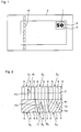
- the security element 1 according to the invention is integrated in a banknote 2 in such a way that the security element 1 differs from the security element 1 shown in FIG FIG. 1 shown front side of the banknote is visible.
- the security element 1 which is designed as a reflective security element with a rectangular outer contour, comprises a first surface area 3 (here the numbers of the number 50) and a second area area 4 adjoining the first area area 3, both surface areas 3 and 4 together fill the entire area, which is limited by the rectangular outer contour.
- the first area 3 is divided into a plurality of reflective pixels 5, a small portion of which is enlarged in FIG FIG. 2 are shown as a plan view.
- the pixels 5 are square here and have an edge length in the range of 10 to several 100 microns.
- the edge length is not greater than 300 microns. In particular, it may be in the range between 20 to 100 microns.
- the edge length of the pixels 5 is selected such that the area of each pixel 5 is at least two orders of magnitude smaller than the area of the first area 3 (numerals of the number 50).
- Each pixel 5 has, in the embodiment described here, a plurality of reflective facets 6 with the same orientation.
- the facets 6 are the inclined surfaces of a reflective sawtooth grid. In a modification not shown, however, it is also possible for several or all pixels 5 to have only one single facet 6 in each case.
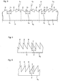
- FIG. 3 the sectional view along the line 7 for three adjacent pixels 5 1 , 5 2 and 5 3 is shown, the illustration in FIG. 3 as well as in the other figures is not true to scale, but partly greatly exaggerated for better presentation. Furthermore, to simplify the illustration in FIG. 3 as well as in FIGS. 4 and 5 the reflective coating on the facets 6 is not drawn.
- the sawtooth grid of the pixels 5 1 , 5 2 and 5 3 is formed in an upper side 8 of a carrier 9, wherein the upper surface thus structured preferably with a reflective coating is coated.
- the carrier 9 may be, for example, a radiation-curing plastic (UV resin) which is applied to a carrier foil, not shown, (for example, a PET foil).
- UV resin radiation-curing plastic
- the inclination ⁇ of the facets 6 in each individual pixel 5 1 , 5 2 and 5 3 is the same. However, the inclination of facets 6 of adjacent pixels 5 1 , 5 2 , 5 3 is different.
- the grating period d 3 of the sawtooth structure of the pixel 5 3 is also different from the grating periods d 1 and d 2 of the sawtooth structures of the pixels 5 1 and 5 2 . Due to the different orientation of the facets 6 of the individual pixels 5 1 , 5 2 and 5 3 incident light along a predetermined direction R L 1 , L 2 , L 3 of each pixel 5 1 , 5 2 , 5 3 directed reflected in different reflection directions as shown schematically in FIG. 3 is shown. Since the facets 6 of the pixels 5 of the first surface area 3 are always oriented differently, a glittering effect or effect comparable to a metallic finish is achieved for the viewer.
- the different orientation of the facets 6 can be adjusted not only by the choice of the inclination angle ⁇ of the facets 6, but also by different azimuth angle ⁇ .
- the azimuth angle ⁇ 1 of the facets 6 of the pixels 5 1 , 5 2 and 5 3 each 90 °.
- the azimuth angle ⁇ 2 of the facets 6 of the pixel 5 4 is about 120 ° (relative to the direction of the arrow P2) and the azimuth angle ⁇ 3 of the facets of the pixel 5 5 is about 280 ° (relative to the Direction of arrow P3).
- the sectional views taken along lines 10, 11 of pixels 5 4 and 5 5 are shown in FIGS. 4 and 5.
- the second surface region 4 can be formed as a normally reflective planar surface, so that the numerals of the number 50 (first surface region 3) clearly stand out from the second surface region 4 due to the described effect.
- the azimuth angles can be chosen at random for example for the individual pixels 5.
- random values between 0 and 360 ° can be selected.
- values from the range of 10 ° to 20 ° and from the range of -20 ° to -10 °, for example, can be selected.
- the slope of the facets from a range of, for example, -20 ° to 20 °. Again, the gradients may be chosen at random.
- the randomly selected slope ⁇ corresponds to a normal distribution.
- the randomly selected azimuth angles ⁇ may in particular be evenly distributed.
- the grating period or width of the saw teeth d is preferably above 1 ⁇ m and in particular above 3 ⁇ m. Furthermore, the grating period d can also be above 5 ⁇ m. However, it is preferably always selected such that at least two facets 6 are present per pixel 5. In particular, at least three, four, or more facets 6 can be contained per pixel 5.
- the facets 6 are preferably formed as flat surface pieces. However, it is also possible that the facets 6 are curved (eg concave or convex). The facets 6 may extend in a straight line, as in the case of the facets 6 of the pixels 5 1 - 5 5 in FIG. 2 is shown. However, it is also a non-linear course (eg, slightly curved) possible, as shown schematically for the pixel 5 6 in FIG. 2 is shown.
- a Colorshift thin-film system 18 or a thin-film system 18 can be vapor-deposited on the upper side 8 or on the reflective coating 12 on the upper side 8, as in FIG FIG. 6 is indicated.
- the reflective coating 12 may be formed as a metal film on which a dielectric layer 13 and an upper metal layer 14, which is partially transparent, are provided.
- a first, second and third layer dielectric thin film system 15, 16, 17, the first and third layers 15, 17 having a higher refractive index than the second layer 16 (FIG. FIG. 7 ).
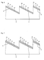
- FIG. 8b a development of the security element 1 according to the invention is shown.
- the orientation of the facets 6 is chosen so that they have only a relatively small angle of inclination in the region of the white stripe shown in white.
- tilt angles in the range of ⁇ 5 ° can be selected.
- the boundaries of the range from which the angles of inclination can be selected shift with increasing distance from the center to larger angles of inclination.
- the azimuth angles are selected from such a range that the mean reflection angle is upwards in the upper region and downward in the lower region.
- FIG. 8a a tilting position is shown in which the lower portion of the security element 1 is tilted into the leaf level and thus the upper part of the security element 1 from the leaf level out. In this case, the strip 20 has apparently moved upwards.
- FIG. 8c the opposite tilt is shown, in which the upper part is tilted into the sheet plane and the lower part of the security element is tilted out of the sheet plane. In this case, the strip 20 has apparently moved downwards. Such an effect is also called "rolling bar".
- the security element 1 is designed as a security thread 19 (FIG. FIG. 1 ) offer arrangements in which not only individual at Tilting migratory strips 20 are present, but the effect is continued periodically.
- a security thread 19 which emerges at certain window areas on the surface of the banknote 2
- a plurality of such effects on z. B. 5 mm repeat can be repeated periodically.
- the effect can therefore always be perceived at least twice, ie there are always at least two bright stripes 20 to see.
- FIGS. 9a to 9c indicate the average orientation of the facets of the individual pixels in such a way that, when the security element 1 is tilted, a beam extending perpendicular to the tilting axis moves along the tilting axis.
- FIGS. 9a to 9c indicated.
- FIG. 9b the appearance of the security element 1 is shown in vertical viewing and lighting.
- FIG. 9a shows the tilt, with the lower side in the leaf level
- FIG. 9c shows the tilt, in which the lower side is tilted out of the sheet plane
- the mean inclination in the region of the strip 20 is relatively low in the position of FIG. 9b and increases continuously to the right and to the left, respectively.
- the azimuth angles are chosen so that the facets in the left area, for example, upwards and in the right area, for example, are aligned downward.
- the described effect can be achieved, whereby here again the glittering impression due to the random variation of the orientation of the facets reaches different pixels is, if only a certain narrow range of variation is given per area.
- the security element 1 can be arranged on a banknote 2 which also contains a security feature based on preferably platelet-shaped magnetic pigments, which are oriented relative to the surface of the banknote in such a way that they form a so-called "rolling bar". Show effect. Such alignments can in particular the US 7,517,578 B2 be removed.
- the security element 1 and the magnetic security feature are arranged relative to one another such that the bright stripe of the security element 1 and the light stripe of the magnetic security feature when tilting the banknote 2 migrate in mutually perpendicular directions.
- the security element according to the invention can be produced by first dividing the first surface area 3 mathematically into the pixels 5. Then, for each pixel 5, a desired orientation is mathematically specified. This can correspond, for example, to the mean expected orientation of a pigment of known security inks. In particular, a grating period or the width of the saw teeth d can be specified. The substantially random variation of the orientations of the facets 6 becomes then preferably realized so that starting from such a preferred orientation, the orientation of the facets 6 of the individual pixels 5 is then varied, for example based on computer-generated random numbers or pseudo-random numbers. Thus, it can be achieved in particular that the orientations of the facets 6 of individual pixels 5 fluctuate by a predetermined average orientation.
- the random variations of orientation can be in one or two dimensions or spatial directions.
- the variation may in particular also relate only to the gradient ⁇ or only to the azimuth angle ⁇ , or the variation of the orientations of the facets 6 may be selected such that a reflected light beam incident in a corresponding sub-region fancles by a predetermined direction of rotation.
- the sawtooth structures of the individual pixels 5 can then be generated, for example, by means of gray scale lithography. This structure can then be galvanically molded and mass-produced on foil in UV varnish 9. Subsequently, the metal film 12 is evaporated and then optionally the thin-film interference coating 18th
- the orientations of the facets 6 of the pixels 5 can be produced with high accuracy, so that a very fine resolution can be achieved on the small length scale of the pixels 5.
- arbitrarily sharp or smooth transitions can be generated by the individual pixels 5. It can be set for each facet 6, the orientation in the manner described and after this determination, then the security element 1 can be made.
- the security element 1 according to the invention can also be used as a security thread 19 (FIG. FIG. 1 ) be formed. Furthermore, the security element 1 can not only as described, are formed on a carrier film from which it can be transferred in a known manner to the document of value. It is also possible to design the security element 1 directly on the value document. Thus, a direct printing with subsequent embossing of the security element can be carried out on a polymer substrate, for example, to form a security element according to the invention in plastic banknotes.
- the security element according to the invention can be formed in a wide variety of substrates.
- a paper with synthetic fibers ie paper with a content x polymeric material in the range of 0 ⁇ x ⁇ 100 wt .-%
- a plastic film for.
- PE polyethylene
- PET polyethylene terephthalate
- PBT polybutylene terephthalate
- PEN polyethylene naphthalate
- PP polypropylene
- PA polyamide
- a multilayer composite in particular a composite of several different films (composite composite) or a
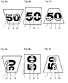
- a further embodiment of the security element 1 according to the invention is shown in plan view, in which the first surface area 3 is again formed by the numbers of the number 50 and the second surface area 4 connects to the first surface area 3, that both surface areas 3 and 4 together the entire area fill, which is limited by the rectangular outer contour of the optically variable surface pattern 1.
- the first area 3 can be used in conjunction with FIGS. 1 to 9 be formed, so that, for example, the inventive glittering effect and / or the described noisy display achieved can be.
- Figures 8a-8c described "rolling bar effect" are provided.
- the second area 4 is here designed as a moiré magnification arrangement, which will be described in detail below, which represents the letter "M" for the observer with absolute depth information.
- the two surface regions can be combined on the same carrier 9 (which may be formed, for example, as a film strip) and shaped in particular in identical operations.
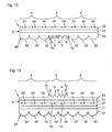
- Fig. 11 is a schematic sectional view of the security element 1 according to FIG. 10 illustrated, wherein the sectional view shows a portion of the first surface area 3, followed by the second surface area 4 on both sides.
- the sectional view according to FIG. 11 is purely schematic and not to scale and serves essentially to explain the structure.
- the carrier 9 As the sectional view according to FIG. 11 can be seen, the carrier 9, a carrier film 21 (which may be, for example, a PET film) and an upper and lower embossing lacquer layer 22, 23.
- a carrier film 21 which may be, for example, a PET film
- an upper and lower embossing lacquer layer 22, 23 As the sectional view according to FIG. 11 can be seen, the carrier 9, a carrier film 21 (which may be, for example, a PET film) and an upper and lower embossing lacquer layer 22, 23.
- facets 6 of the pixels 5 2 and 5 3 are shown schematically. By means of the facets 6, the desired reflection of the individual pixels 5 2 , 5 3 is achieved.
- microstructures 24, which in particular can be filled with color, are formed in the lower embossing lacquer layer 23.
- the microstructures 24 are in a plane perpendicular to the plane of FIG. 11 in a grid with a fixed geometry (here, for example, a hexagonal grid) and thus arranged flat in a first microstructure pattern.
- the upper embossing lacquer layer 22 is formed such that it has a multiplicity of microlenses 25 in the second area region 4.
- the microlenses 25 are in a plane perpendicular to the plane of FIG. 11 in a grid with a fixed geometry (here, for example, a hexagonal grid) and thus arranged flat in a first pattern, wherein the first pattern adapted to the first microstructure pattern and both patterns are aligned such that upon viewing the security element 1, the microlenses 25 together form a moiré magnification arrangement with the microstructures 24.
- the basic principle of a moire magnification arrangement is for example in WO 2006/087138 A1 described, the entire contents of which are hereby incorporated.
- the moiré magnification arrangement in the second surface part 4 forms a micro-optical representation arrangement 26, with which here, as will be described in detail below, the letter "M" is repeatedly displayed to the observer so that it appears behind the security element 1. This is achieved by presenting the viewer's left and right eyes LA and RA with different views of the object to be displayed (here the letter "M"), which show the object in each case viewed from the corresponding direction.
- the object is drawn as a point to simplify the representation, with the right Eye RA of the observer sees the object at position 27 and the left eye LA of the observer sees the object at position 28.
- the viewer sees with his two eyes the object under the different directions 29, 30, which intersect at the position 31, so that the object is located at the position 31 and therefore at a distance t1 behind the security element 1 for the viewer. For the viewer, this results in absolute depth information for the object.
- the moire magnification arrangement in the second surface area 4 achieves an absolute depth effect, in which the viewer sees the periodically repeating letter "M" lying at depth t1.
- the microstructures 24 may, as already mentioned, preferably be filled with color, so that the letters "M" on the one hand and the remaining area of the second surface area 4 on the other appear dull, but of different colors.
- the micro-optical representation arrangement 26 may be designed not only as a moiré magnification arrangement, but also, for example, as a modulo magnification arrangement, as described, for example, in US Pat WO 2009/000528 A1 is described.
- the content relating to the formation of a modulo magnification arrangement of WO 2009/000528 A1 is hereby incorporated into the present application.
- the image to be displayed need not necessarily be periodic from a grid put together repetitive individual motifs. It can be displayed a complex frame with high resolution.
- the image to be displayed usually consists of individual motifs (here microstructures 24) periodically arranged in a grid and enlarged by the lenses 25, the area associated with each individual motif being at most about the area of the corresponding lens cell equivalent.
- the microlenses 25 as well as the sawtooth structures for the reflective facets 6 can be produced simultaneously by means of only a single embossing of the embossing layer 22. Subsequently, only the facets 6 are to be metallized so that they have a reflective effect. The structure according to FIG. 11 is therefore fast to produce.
- FIG. 13 a modification of the security element 1 according to the invention is shown, in which the micro-optical representation arrangement 26 instead of the microlenses 25 concave mirror 32, which are formed by embossing the lower embossing lacquer layer 23 and applying a reflective coating.
- the facets 6 of the pixels 5 2 , 5 3 are also formed on the lower embossing lacquer layer 23. They can be formed in the same way as the micro-hollow mirrors 32 by embossing and mirroring. Preferably, the micro-cavities 32 and the facets are embossed in the same step and mirrored in the same step.
- the microstructures 24 may be provided not only in the second surface area 4 but also in the first area area 3 and thus above the facets 6. This facilitates the production of the security element 1. However, they can also be omitted.
- the first surface area 3 may (but does not have to) also appear slightly colored.
- FIG. 14 a construction of the security element 1 is shown, in which the micro hollow mirror 32, the microstructures 24 and the facets 6 are each embossed in a separate embossing lacquer layer 23,22 and 33. Between the embossing lacquer layers 23 and 22 is a first carrier foil 21 and between the embossing lacquer layers 22 and 33 a second carrier foil 34 is provided.
- micro-cavity mirror 32 and the facets 6 can be metallized differently, for example with different metals or coatings with color-shifting effects (eg thin-film systems in which the color varies depending on the viewing angle).
- a further protective lacquer layer (not shown) may be provided so that the resistance and protection against impressions can be increased by counterfeiters.
- the micro-optical representation arrangement 26 instead of a Mikrofokussierelementrasters (grid of the microlenses 25 or grid of the micro-hollow mirrors 32) also have only a breadboard 35, as in FIG. 15 is shown.
- a perforated grid 35 can be realized for example by periodically arranged holes or slots in an opaque, for example, mirror-metallized layer.
- the holes can be small recesses. In this case, the holes may be referred to as positive holes. It can also be provided so-called negative holes, in which the holes are small, non-transparent or non-reflective areas.
- the perforated grid also extends into the first area region 3, so that superimposition of the representations results in the first area region 3.
- the security element 1 can also be designed so that no hole pattern is present in the first surface area 3.
- the micro-optical representation arrangement 26 can be realized by means of diffractive structures.
- a hologram with a stereographic 3D representation can be provided, which is made up of microscopically small sinusoidal gratings.
- the object represented by means of the micro-optical representation arrangement 26 may also seem to lie or float in front of the security element 1.
- the microoptical representation arrangement 26 and / or the facets 6 can / may be wholly or partially provided with a color-shifting coating, in particular a thin film with reflector / dielectric / absorber. This further enhances the visual attractiveness and further increases the security against counterfeiting.
- the micro-optical representation arrangement 26 in the second area region 4 was designed such that a stereographic representation with depth information is achieved.
- These are understood here representations in which a three-dimensional effect is generated by the fact that the security element 1 provides the left and right eye of the observer different views of an object, which show the object viewed from the respective direction. From these different views, an absolute depth information then results for a viewer, from which a total of three-dimensional impression results.
- the representations used in this class can often have more than just two different views, which usually results in parallax (i.e., when rotated, the image components move in the foreground relative to the image components in the image background). Under certain circumstances, for example, you can also look behind an object standing in the foreground by turning.
- holograms for example directly exposed holograms or computer-generated stereograms.
- microlens tilt images and moire magnification arrangements with depth effect or motion effect as eg in US Pat WO 2007/076952 A2 or WO 2009/000527 A1 is described.
- the micro-optical representation arrangement 26 in such a way that the parallax does not exactly correspond to the parallax of an object lying in the depth.
- This can be realized, for example, by moiré magnification arrangements or modulo magnification arrangements. It can thereby be achieved that when tilting or turning the security element 1, an additional movement effect in the second area 4 occurs. It may be an orthoparallactic movement, as z. B. in the WO 2007/076952 A2 Strictly speaking, the representations for the left and right eyes of the observer allow no assignment of a depth, since the viewing directions, under which the observer sees the object with the left and right eye, do not intersect.
- the representation can change from a first image into a second image by means of the micro-optical representation arrangement 26 when the security element 1 is tilted or rotated.
- an in-depth could Image of a first symbol A when tilting the security element 1 in at least one other representation, such as a symbol B, tilt.
- the micro-optical representation arrangement 26 can also realize additional effects, for example tilt images or kinematic effects (movements, pump effect, etc.).
- the three-dimensional representation in the second surface area 4 can move when tilting the security element 1.
- the representation could also tilt from a certain tilt angle in the representation of a completely different, not necessarily three-dimensional appearing object (for example, a lying in the depth number in another representation, for example, a further tilting then moving symbol, change).
- micro-optical representation arrangement 26 can be upgraded to the security element 1 according to the invention with extremely little effort.
- the security element 1 according to the invention can also be referred to as an optically variable surface pattern and z. B. are used for purely decorative purposes.
- FIG. 16 schematically an embossing tool 36 is shown, with which the facets 6 and the microlenses 25 in the upper embossing lacquer layer 22 of the security element 1 according to Fig. 11 can be shaped.
- the embossing tool 36 has an embossing surface 37, in which the inverted shape of the surface structure to be embossed is formed.
- embossing tool can be provided in the same way.
Abstract
Die Erfindung betrifft ein Sicherheitselement (1) für ein Sicherheitspapier, Wertdokument oder dergleichen, mit einem Träger (9), der einen reflektiven Flächenbereich (3) aufweist, der in eine Vielzahl von reflektiven Pixeln (5) aufgeteilt ist, wobei die Fläche jedes Pixels (5) um zumindest eine Größenordnung kleiner ist als die Fläche des reflektiven Flächenbereiches (3), wobei jedes Pixel (5) zumindest eine reflektive Facette aufweist, die in einer Oberfläche des Trägers ausgebildet ist, wobei die zumindest eine reflektive Facette auf den Flächenbereich (3) entlang einer vorbestimmten Richtung einfallendes Licht gerichtet in eine durch ihre Orientierung vorgegebene Reflexionsrichtung reflektiert, wobei der reflektive Flächenbereich auf dem Träger in zumindest zwei Teilbereiche aufgeteilt ist, wobei in einem ersten Teilbereich die Orientierungen der Facetten unterschiedlicher Pixel (5) über den reflektiven Flächenbereich eine im Wesentlichen zufällige Variation aufweisen und in zumindest einem weiteren Teilbereich die Orientierungen der Facetten unterschiedlicher Pixel über den reflektiven Flächenbereich derart sind, dass einfallendes Licht jeweils in einen engen Winkelbereich reflektiert wird.The invention relates to a security element (1) for a security paper, document of value or the like, with a support (9) having a reflective surface area (3) divided into a plurality of reflective pixels (5), wherein the area of each pixel (5) is at least an order of magnitude smaller than the area of the reflective surface area (3), wherein each pixel (5) has at least one reflective facet formed in a surface of the carrier, wherein the at least one reflective facet reflects light incident on the surface area (3) along a predetermined direction, directed in a direction of reflection predetermined by its orientation, wherein the reflective surface area on the carrier is divided into at least two partial areas, wherein in a first sub-area the orientations of the facets of different pixels (5) over the reflective area have a substantially random variation and in at least one other sub-area the orientations of the facets of different pixels over the reflective area are such that incident light is in each case narrow Angle range is reflected.
Description
Die vorliegende Erfindung betrifft ein Sicherheitselement für ein Sicherheitspapier, Wertdokument oder dergleichen, ein Wertdokument mit einem solchen Sicherheitselement sowie ein Verfahren zum Herstellen eines solchen Sicherheitselementes.The present invention relates to a security element for a security paper, value document or the like, a value document with such a security element and a method for producing such a security element.
Zu schützende Gegenstände werden häufig mit einem Sicherheitselement ausgestattet, das die Überprüfung der Echtheit des Gegenstandes erlaubt und zugleich als Schutz vor unerlaubter Reproduktion dient.Items to be protected are often provided with a security element that allows verification of the authenticity of the item and at the same time serves as protection against unauthorized reproduction.
Zu schützende Gegenstände sind beispielsweise Sicherheitspapiere, Ausweis- und Wertdokumente (wie z.B. Banknoten, Chipkarten, Pässe, Identifikationskarten, Ausweiskarten, Aktien, Anlagen, Urkunden, Gutscheine, Schecks, Eintrittskarten, Kreditkarten, Gesundheitskarten, etc.) sowie Produktsicherungselemente, wie z.B. Etiketten, Siegel, Verpackungen, etc.Items to be protected include, for example, security papers, identity and value documents (such as banknotes, chip cards, passports, identification cards, identity cards, stocks, attachments, certificates, vouchers, checks, tickets, credit cards, health cards, etc.) as well as product security elements such as security items. Labels, seals, packaging, etc.
Für ein solches Sicherheitselement ist es bekannt, optisch variable Sicherheitsfarben zu verwenden, wie sie z.B. in der
Es ist ferner bekannt, solche Pigmente mit einer zusätzlichen magnetischen Schicht zu versehen (
Aus der
Die beschriebenen optisch variablen Sicherheitsfarben sind einerseits relativ teuer. Andererseits ist die Ausrichtung der Pigmente über Magnete natürlich limitiert, da die zur Ausrichtung nötigen Magnetfelder nicht beliebig geformt werden können. Weiterhin können die Sicherheitselemente nicht besonders fein aufgelöst werden, was zum einen in den meist verwendeten Siebdruckverfahren und zum anderen in den nicht beliebig scharfen Übergängen der nötigen Magnetfelder begründet ist.The described optically variable security colors are on the one hand relatively expensive. On the other hand, the orientation of the pigments via magnets is of course limited, since the magnetic fields necessary for alignment can not be arbitrarily shaped. Furthermore, the security elements can not be resolved particularly fine, which is due to the one in the most commonly used screen printing and the other in the not arbitrarily sharp transitions of the necessary magnetic fields.
Neben der Farbänderung führen die Sicherheitsfarben auch häufig zu einem glitzernden Effekt ähnlich zu Metallic-Lackierung bei Kraftfahrzeugen.In addition to the color change, the security colors also often lead to a glittering effect similar to metallic paint in motor vehicles.
Davon ausgehend liegt der Erfindung die Aufgabe zugrunde, die Nachteile des Standes der Technik zu vermeiden und insbesondere, ein Sicherheitselement zur Verfügung zu stellen, mit dem zumindest einer der beschriebenen Effekte (wie z.B. der Glitzereffekt) der Sicherheitsfarben ohne die Verwendung von Sicherheitsfarben erreicht werden kann.Based on this, the object of the invention is to avoid the disadvantages of the prior art and, in particular, to provide a security element with which at least one of the described effects (such as the glitter effect) of the security colors can be achieved without the use of security inks ,
Erfindungsgemäß wird die Aufgabe gelöst durch ein Sicherheitselement für ein Sicherheitspapier, Wertdokument oder dergleichen, mit einem Träger, der einen reflektiven Flächenbereich aufweist, der in eine Vielzahl von reflektiven Pixeln aufgeteilt ist, wobei die Fläche jedes Pixels um zumindest eine Größenordnung kleiner ist als die Fläche des reflektiven Flächenbereiches, wobei jedes Pixel zumindest eine reflektive Facette aufweist, die in einer Oberfläche des Trägers ausgebildet ist, wobei die zumindest eine reflektive Facette auf den Flächenbereich entlang einer vorbestimmten Richtung einfallendes Licht gerichtet in eine durch ihre Orientierung vorgegebene Reflexionsrichtung reflektiert, wobei die Orientierungen der Facetten unterschiedlicher Pixel über den reflektiven Flächenbereich eine im Wesentlichen zufällige Variation aufweisen.According to the invention, the object is achieved by a security element for a security paper, value document or the like, having a carrier which has a reflective surface area which is divided into a multiplicity of reflective pixels, the area of each pixel being smaller by at least an order of magnitude than the area of the reflective surface area, each pixel having at least one reflective facet formed in a surface of the substrate, the at least one reflective facet reflecting light incident on the area along a predetermined direction in a direction of reflection predetermined by its orientation, the orientations the facets of different pixels over the reflective surface area have a substantially random variation.
Unter "Pixeln" werden hier kleine Teilbereiche des reflektiven Flächenbereichs verstanden, die nicht nur eine beliebige Umrissform haben können, sondern insbesondere auch nicht auf einem regelmäßigen Raster angeordnet sein müssen,"Pixels" are here understood to mean small subareas of the reflective surface area, which not only can have any desired outline shape, but in particular also need not be arranged on a regular grid,
Die gewählte Formulierung, nach der die Orientierungen der Facetten unterschiedlicher Pixel über den reflektiven Flächenbereich eine im Wesentlichen zufällige Variation aufweisen, trägt dabei der Tatsache Rechnung, dass eine zufällige Variation auch beispielsweise mithilfe computergenerierter "Zufallszahlen" realisiert werden kann, die streng genommen deterministisch sind.The chosen formulation, according to which the orientations of the facets of different pixels over the reflective surface area essentially one have random variation, taking into account the fact that a random variation can also be realized for example by means of computer-generated "random numbers", which are strictly deterministic.
Die im Wesentlichen zufällige Variation der Orientierungen der Facetten wird vorzugsweise so realisiert, dass den Pixeln z. B. bereichsweise zunächst eine gewisse Vorzugsorientierung zugeordnet wird, von der ausgehend die Orientierung der Facetten der einzelnen Pixel dann beispielsweise auf Basis computergenerierter Zufallszahlen oder Pseudo-Zufallszahlen variiert wird. Somit lässt sich insbesondere erreichen, dass die Orientierungen der Facetten einzelner Pixel um eine bereichsweise vorgegebene mittlere Orientierung schwanken. Die zufällige Schwankung der Orientierung kann in besonderen Ausführungsvarianten nur in vorgegebenen Grenzen und/ oder entsprechend einer vorgegebenen Verteilung, beispielsweise normal- oder gleichverteilt, vorliegen.The substantially random variation of the orientations of the facets is preferably realized in such a way that the pixels z. For example, if a certain preferred orientation is assigned in certain regions, the orientation of the facets of the individual pixels is then varied on the basis of computer-generated random numbers or pseudo-random numbers, for example. Thus, it can be achieved, in particular, that the orientations of the facets of individual pixels fluctuate around a region-wise predetermined average orientation. The random variation of the orientation can be present in specific embodiments only within predetermined limits and / or according to a predetermined distribution, for example, normal or uniformly distributed.
Mit einem solchen Sicherheitselement ist es möglich, für jedes Pixel die Orientierung und damit auch die Richtung, in die einfallendes Licht reflektiert wird, genau einzustellen, so dass auf einfache Art und Weise ein Glitzereffekt verwirklicht werden kann. Bei dem erfindungsgemäßen Sicherheitselement kann somit die reflektive Fläche, die z.B. eine ebene oder eine gekrümmte Fläche sein kann, immer noch als ebene bzw. gekrümmte Fläche wahrgenommen werden, wobei sie aber den gewünschten Glitzereffekt zeigt.With such a security element, it is possible to precisely adjust the orientation and thus also the direction in which incident light is reflected for each pixel, so that a glittering effect can be realized in a simple manner. In the case of the security element according to the invention, the reflective surface, which is e.g. may be a flat or curved surface, still perceived as a flat or curved surface, but showing the desired glittering effect.
Unter der im Wesentlichen zufälligen Variation der Orientierungen der Facetten über den reflektiven Flächenbereich wird hier insbesondere verstanden, dass für die Mehrzahl der Paare unmittelbar benachbarter Pixel oder auch für alle Paare unmittelbar benachbarter Pixel die Reflexionsrichtungen unterschiedlich sind. Bevorzugt ist dabei für einen Betrachter der Flächenbereich in seiner tatsächlichen Raumform wahrnehmbar.The substantially random variation of the orientations of the facets over the reflective surface area is understood here in particular to mean that for the majority of the pairs of directly adjacent pixels or also for all pairs of immediately adjacent pixels, the reflection directions are different. For a viewer, the surface area is preferably perceptible in its actual spatial form.
Das erfindungsgemäße Sicherheitselement kann insbesondere ein optisches Erscheinungsbild aufweisen, das dem magnetisch ausgerichteter Pigmente optisch variabler Sicherheitsfarben praktisch gleicht. Dazu wählt man eine Pixelgröße, die etwa der Größe der in solchen Farben verwendeten Pigmente entspricht, beispielsweise 30 µm, und wählt die mittlere Orientierung der Facetten unterschiedlicher Pixel analog zur mittleren Orientierung der Pigmente. Der Glitzereffekt solcher Farben beruht darauf, dass die einzelnen Pigmente nicht exakt in eine vorgegebene Richtung reflektieren, sondern dass eine gewisse zufällige Variation der Reflexionsrichtungen vorliegt. Die Orientierungen der Facetten unterschiedlicher Pixel weisen beim erfindungsgemäßen Sicherheitselement ebenfalls eine solche Variation auf, woraus sich ein vergleichbarer Glitzereffekt ergibt.The security element according to the invention may in particular have an optical appearance which is practically the same as the magnetically oriented pigments of optically variable security colors. For this purpose one chooses a pixel size which corresponds approximately to the size of the pigments used in such colors, for example 30 μm, and selects the average orientation of the facets of different pixels analogously to the average orientation of the pigments. The glittering effect of such colors is based on the fact that the individual pigments do not reflect exactly in a given direction, but that there is a certain random variation of the reflection directions. The orientations of the facets of different pixels also have such a variation in the security element according to the invention, resulting in a comparable glitter effect.
Unter der Fläche des Flächenbereiches sowie der Fläche der Pixel wird hier insbesondere jeweils die Fläche bei Projektion in Richtung der makroskopischen Flächennormalen des Flächenbereiches auf eine Ebene verstanden. Bevorzugt ist die Fläche jedes Pixels um zumindest zwei Größenordnungen kleiner als die Fläche des reflektiven Flächenbereiches.In this case, the area of the surface area as well as the area of the pixels is to be understood as meaning in particular the area when projected in the direction of the macroscopic surface normal of the surface area onto a plane. Preferably, the area of each pixel is at least two orders of magnitude smaller than the area of the reflective area.
Bei dem erfindungsgemäßen Sicherheitselement weisen die Orientierungen der Facetten unterschiedlicher Pixel mit Vorteil eine im Wesentlichen zufällige Variation um bereichsweise vorgegebene unterschiedliche mittlere Orientierungen auf.In the case of the security element according to the invention, the orientations of the facets of different pixels advantageously have an essentially random variation by regions of different predetermined mean orientations.
Mehrere der Pixel weisen vorzugsweise jeweils mehrere reflektive Facetten gleicher Orientierung auf, die ein periodisches oder aperiodisches Sägezahngitter bilden. Es können auch alle Pixel jeweils mehrere, bevorzugt die gleiche Anzahl von reflektiven Facetten gleicher Orientierung aufweisen.Several of the pixels preferably each have a plurality of reflective facets of the same orientation, which form a periodic or aperiodic sawtooth grid. It is also possible for all the pixels to have a plurality of, preferably the same number of reflective facets of the same orientation.
Die Facetten sind bevorzugt als im Wesentlichen ebene Flächenstücke ausgebildet, was die Herstellung erleichtert. Die gewählte Formulierung, nach der die Facetten als im Wesentlichen ebene Flächenstücke ausgebildet sind, trägt dabei der Tatsache Rechnung, dass sich in der Praxis herstellungsbedingt in der Regel nie perfekt ebene Flächenstücke herstellen lassen. Die Facetten können alternativ auch als gekrümmte (z. B. konkav, konvex oder gewellt) Flächenstücke ausgebildet sein. Die Krümmung der Flächenstücke ist dabei zweckmäßig gering.The facets are preferably formed as substantially planar surface pieces, which facilitates the production. The chosen formulation, according to which the facets are formed as essentially flat surface pieces, takes account of the fact that in practice production-related generally never perfectly flat surface pieces can be produced. The facets may alternatively also be formed as curved (for example concave, convex or wavy) surface pieces. The curvature of the patches is expediently low.
Unter Orientierung wird hier insbesondere die Neigung der reflektiven Facetten und/ oder der Azimut-Winkel der reflektiven Facetten verstanden. Natürlich kann die Orientierung der Facetten auch durch andere Parameter bestimmt sein. Insbesondere handelt es sich dabei um zwei zueinander orthogonale Parameter, wie z. B. die zwei Komponenten des Normalenvektors der jeweiligen Facette.Orientation is understood here in particular as the inclination of the reflective facets and / or the azimuth angle of the reflective facets. Of course, the orientation of the facets can also be determined by other parameters. In particular, these are two mutually orthogonal parameters, such. B. the two components of the normal vector of each facet.
Die zufällige Variation der Orientierungen kann dabei in einer oder zwei Dimensionen bzw. Raumrichtungen erfolgen. Das erfindungsgemäße Sicherheitselement kann insbesondere so ausgebildet sein, dass die Orientierungen der Facetten unterschiedlicher Pixel nur in einem der die Orientierung der Facetten bestimmenden Parameter eine im Wesentlichen zufällige Variation aufweisen. So kann die zufällige Variation insbesondere auch nur die Steigung oder nur den Azimutwinkel betreffen, oder die Variation der Orientierungen der Facetten kann so gewählt werden, dass ein in einem entsprechenden Teilbereich einfallender reflektierter Lichtstrahl um eine vorgegebene Drehrichtung "auffächert".The random variation of the orientations can take place in one or two dimensions or spatial directions. The security element according to the invention can in particular be designed such that the orientations of the facets of different pixels have a substantially random variation only in one of the parameters determining the orientation of the facets. Thus, the random variation can relate in particular only to the slope or only to the azimuth angle, or the variation of the orientations of the facets can be selected such that one in a corresponding one Partial area incident reflected light beam by a predetermined direction of rotation "fanning".
Vorzugsweise beträgt die durch die Variation der Orientierungen der Facetten unterschiedlicher Pixel vorgegebene Variation der Reflexionsrichtungen mindestens etwa 1°, bevorzugt mindestens etwa 3°, besonderes bevorzugt mindestens etwa 10°.The variation of the reflection directions predetermined by the variation of the orientations of the facets of different pixels is preferably at least about 1 °, preferably at least about 3 °, particularly preferably at least about 10 °.
Bei dem erfindungsgemäßen Sicherheitselement können die reflektiven Facetten eine reflexionserhöhende, insbesondere eine reflektierende Beschichtung aufweisen. Reflexionserhöhende Beschichtungen im Sinne der Erfindung sind auch Beschichtungen, die den Reflexionsgrad beispielsweise nur von etwa 20% auf etwa 50% erhöhen, wie z.B. semitransparente Schichten, wohingegen bei reflektierenden Beschichtungen ein sehr hoher Reflexionsgrad vorliegt. Die reflexionserhöhende Beschichtung kann eine metallische Beschichtung sein, die beispielsweise aufgedampft ist. Als Beschichtungsmaterial kann insbesondere Aluminium, Gold, Silber, Kupfer, Palladium, Chrom, Nickel und/ oder Wolfram sowie deren Legierungen verwendet werden. Alternativ kann die reflexionserhöhende Beschichtung durch eine Beschichtung mit einem Material mit hohem Brechungsindex gebildet werden.In the case of the security element according to the invention, the reflective facets can have a reflection-enhancing, in particular a reflective coating. Reflection-enhancing coatings in the context of the invention are also coatings which increase the reflectance, for example, only from about 20% to about 50%, such as e.g. semi-transparent layers, whereas reflective coatings have a very high reflectance. The reflection-enhancing coating may be a metallic coating, for example vapor-deposited. In particular aluminum, gold, silver, copper, palladium, chromium, nickel and / or tungsten and their alloys can be used as the coating material. Alternatively, the reflection enhancing coating may be formed by a coating with a high refractive index material.
Insbesondere kann auf den Facetten zumindest bereichsweise eine farbkippende Schicht ausgebildet sein. Damit ist die gewünschte farbkippende Wirkung auf Pixelgröße und somit hoch aufgelöst einstellbar. Gemäß einer vorteilhaften Ausgestaltung können auch bereichsweise unterschiedliche farbkippende Schichten auf den Facetten ausgebildet sein.In particular, a color-shifting layer may be formed on the facets at least in regions. Thus, the desired color-shifting effect on pixel size and thus high resolution adjustable. According to an advantageous embodiment, regions of different color-shifting layers can also be formed on the facets.
Sowohl die reflexionserhöhende Beschichtung als auch die farbkippende Schicht können in Form von Mustern, Zeichen oder Codierungen vorliegen und/ oder Aussparungen in Form von Mustern, Zeichen oder Codierungen aufweisen.Both the reflection-enhancing coating and the color-shifting layer may be in the form of patterns, characters or codes and / or have recesses in the form of patterns, characters or codes.
Die maximale Ausdehnung eines Pixels liegt vorzugsweise zwischen etwa 5 µm und 5 mm, bevorzugt zwischen 10 µm und 300 µm, besonders bevorzugt zwischen 20µm und 100 µm.The maximum extent of a pixel is preferably between about 5 μm and 5 mm, preferably between 10 μm and 300 μm, particularly preferably between 20 μm and 100 μm.
Die Breite der Sägezähne bzw. im Fall periodischer Sägezahngitter die Gitterperiode pro Pixel liegt vorzugsweise zwischen 1 µm und 300 zum, bevorzugt zwischen 3 µm und 100 µm, besonders bevorzugt zwischen 5 µm und 30 µm. Die Breite der Sägezähne bzw. die Gitterperiode wird insbesondere so gewählt, dass pro Pixel zumindest zwei Facetten gleicher Orientierung enthalten sind und dass Beugungseffekte praktisch keine Rolle mehr spielen für einfallendes Licht (z.B. aus dem Wellenlängenbereich von 380 nm bis 750 nm). Da keine bzw. keine praktisch relevanten Beugungseffekte auftreten, können die Facetten als achromatische Facetten bzw. die Pixel als achromatische Pixel bezeichnet werden, die eine gerichtet achromatische Reflexion bewirken. Das Sicherheitselement weist somit bezüglich der durch die Facetten der Pixel vorhandenen Gitterstruktur eine achromatische Reflektivität auf, wobei das Sicherheitselement mit zunehmender Gitterperiode ein zunehmend brillanteres Erscheinungsbild, d. h. einen ausgeprägteren Gitzereffekt zeigt. Eine eventuell noch vorhandene Sichtbarkeit eines auf die Sägezahngitter zurückgehenden Beugungsbildes kann - sollte dies gewünscht sein - insbesondere durch eine Variation der Gitterperiode minimiert werden.The width of the saw teeth or, in the case of periodic sawtooth gratings, the grating period per pixel is preferably between 1 μm and 300 μm, preferably between 3 μm and 100 μm, particularly preferably between 5 μm and 30 μm. In particular, the width of the saw teeth or the grating period is selected such that at least two facets of the same orientation are contained per pixel and that diffraction effects play virtually no role for incident light (for example from the wavelength range from 380 nm to 750 nm). Since no or no practically relevant diffraction effects occur, the facets can be referred to as achromatic facets and the pixels as achromatic pixels, which cause a directed achromatic reflection. The security element thus exhibits an achromatic reflectivity with respect to the lattice structure present through the facets of the pixels, the security element having an increasingly brilliant appearance as the lattice period increases. H. shows a more pronounced Gitzereffekt. Any remaining visibility of a diffraction pattern going back to the sawtooth grid can - if desired - be minimized in particular by a variation of the grating period.
Die farbkippende Schicht kann insbesondere als Dünnschichtsystem bzw. Dünnfilm-Interferenzbeschichtung ausgebildet sein. Dabei kann z.B. eine Schichtfolge Metallschicht - dielektrische Schicht - Metallschicht oder eine Schichtfolge aus mindestens drei dielektrischen Schichten, wobei die Brechzahl der mittleren Schicht geringer ist als die Brechzahl der beiden anderen Schichten, verwirklicht werden. Als dielektrisches Material kann z.B. ZnS, SiO2, TiO2, MgF2 verwendet werden.The color-shifting layer can be designed in particular as a thin-layer system or thin-film interference coating. Here, for example, a Layer sequence metal layer - dielectric layer - metal layer or a layer sequence of at least three dielectric layers, wherein the refractive index of the middle layer is less than the refractive index of the other two layers, realized. As the dielectric material, for example, ZnS, SiO 2 , TiO 2 , MgF 2 can be used.
Die farbkippende Schicht kann auch als Interferenzfilter, dünne semitransparente Metallschicht mit selektiver Transmission durch Plasmaresonanzeffekte, Nanopartikel, etc. ausgebildet sein. Die farbkippende Schicht kann insbesondere auch als Flüssigkristallschicht, diffraktive Reliefstruktur oder Sub-Wellenlängengitter realisiert sein. Auch ein Dünnfilmsystem mit einem Aufbau Reflektor, Dielektrikum, Absorber (in dieser Reihenfolge auf den Facetten ausgebildet bzw. bei Betrachtung des Sicherheitselements durch den Träger hindurch in der umgekehrten Reihenfolge) ist möglich. Soll das Sicherheitselement von beiden Seiten betrachtet werden können, bietet sich die Schichtfolge Absorber/ Dielektrikum/ Reflektor/ Dielektrikum/ Absorber an.The color-shifting layer may also be formed as an interference filter, thin semitransparent metal layer with selective transmission by plasma resonance effects, nanoparticles, etc. The color-shifting layer can in particular also be realized as a liquid-crystal layer, diffractive relief structure or sub-wavelength grating. A thin-film system with a reflector, dielectric, absorber structure (formed on the facets in this order or in reverse order when the security element is viewed through the carrier) is also possible. If the security element can be viewed from both sides, the layer sequence absorber / dielectric / reflector / dielectric / absorber can be used.
Bei dem erfindungsgemäßen Sicherheitselement können pro Pixel bevorzugt zumindest zwei Facetten vorgesehen sein. Es können auch drei, vier, fünf oder mehr Facetten sein.In the case of the security element according to the invention, preferably at least two facets can be provided per pixel. It can also be three, four, five or more facets.
Das Sicherheitselement kann insbesondere so ausgebildet sein, dass die Azimut-Winkel der Facetten der einzelnen Pixel zufällig verteilte Werte zwischen 0° und 360° sind (aber pro Pixel weist jede Facette den gleichen Azimut-Winkel auf). Auch ist es möglich, dass die Steigungen der Facetten pro Pixel zufällig gemäß einer Normalverteilung verteilt sind (auch hier weist pro Pixel jede Facette die gleiche Steigung auf).In particular, the security element may be designed such that the azimuth angles of the facets of the individual pixels are randomly distributed values between 0 ° and 360 ° (but each facet has the same azimuth angle per pixel). It is also possible for the slopes of the facets per pixel to be randomly distributed according to a normal distribution (here, too, each facet has the same slope per pixel).
Der reflektive Flächenbereich des Sicherheitselementes kann in zumindest zwei Teilbereiche bzw. Abschnitte aufgeteilt sein, in denen die Pixel unterschiedliche mittlere Orientierungen bzw. durch die unterschiedlichen mittleren Orientierungen vorgegebene unterschiedliche mittlere Reflexionsrichtungen haben. So können z.B. alle Facetten den gleichen Azimut-Winkel aufweisen. In dem ersten der beiden Teilbereiche sind dann die Neigungen der Facetten beispielsweise zufällig zwischen 10° und 20° gewählt, während die Neigungen der Facetten im zweiten Teilbereich der beiden Teilbereiche zwischen -20° und -10° gewählt sind. Beim Kippen des Sicherheitselementes erscheint dann je nach Beleuchtung mal der erste und mal der zweite Teilbereich hell, d.h. die Darstellung "flippt" von einer positiven in eine negative Darstellung.The reflective surface area of the security element can be divided into at least two partial areas or sections in which the pixels have different average orientations or different mean reflection directions predetermined by the different central orientations. Thus, e.g. all facets have the same azimuth angle. In the first of the two subregions, for example, the inclinations of the facets are randomly selected between 10 ° and 20 °, while the inclinations of the facets in the second subrange of the two subregions are selected between -20 ° and -10 °. When tilting the security element then appears depending on the lighting times the first and sometimes the second portion bright, i. the representation "flips" from a positive to a negative representation.
Alternativ können z.B. auch die Azimutwinkel über alle möglichen Winkel gleichverteilt sein und die Neigungen in den zwei Teilbereichen unterschiedlich, aber jeweils fest sein, beispielsweise 10° im ersten Teilbereich und 30° im zweiten Teilbereich. Eine solche Darstellung hat die besondere Eigenschaft, dass diese zwar beim Kippen des Sicherheitselements von einer positiven in eine negative Darstellung "flippt", beim Drehen des Sicherheitselements innerhalb seiner Ebene überraschenderweise aber ein solcher "Flip"-Effekt ausbleibt.Alternatively, e.g. Also, the azimuth angle over all possible angles be uniformly distributed and the inclinations in the two sub-areas different, but each be fixed, for example, 10 ° in the first subarea and 30 ° in the second subarea. Such a representation has the special property that while it "flips" when tilting the security element from a positive to a negative representation, when turning the security element within its level surprisingly fails such a "flip" effect.
Wenn die Facetten eine farbkippende Schicht aufweisen, können die Farben der verschiedenen Teilbereiche unterschiedlich sein, da man unter verschiedenen Winkeln auf die farbkippende Beschichtung blickt.If the facets have a color-shifting layer, the colors of the different regions can be different, since the color-tilting coating is viewed at different angles.
Gemäß einer bevorzugten Ausgestaltung können die zwei Teilbereiche auch auf verschiedene, ineinander verschachtelte Teilflächen verteilt sein. Auf diese Weise lässt sich beispielsweise ein so genanntes Kippbild erzeugen.According to a preferred embodiment, the two partial areas can also be distributed to different, nested partial areas. In this way, for example, a so-called tilt image can be generated.
Ferner kann bei dem erfindungsgemäßen Sicherheitselement der Eindruck erzeugt werden, dass eine "verrauschte" Fläche (bevorzugt in einer reflektiven Fläche) vorliegt. Zusätzlich können die Facetten der Pixel so orientiert sein, dass unter bestimmten Betrachtungswinkeln ein gleichzeitiges helles Aufleuchten vieler Pixel auftritt. Dazu wird der reflektive Flächenbereich auf dem Träger in zumindest zwei Teilbereiche aufgeteilt, so dass die Pixel im ersten Teilbereich eine zufällige Orientierung haben, während die Pixel des zweiten oder der weiteren Teilbereiche jeweils pro Teilbereich alle die gleiche bzw. zumindest nahezu gleiche Orientierung aufweisen. Das Licht einer Lichtquelle wird dann im ersten Teilbereich unter vielen Winkeln in alle Richtungen gestreut, während das Licht in den weiteren Teilbereich in jeweils in einen engen Winkelbereich reflektiert wird. Ein Betrachter sieht dann unter den meisten Winkeln nur eine verrauschte Darstellung mit zufällig aufleuchtenden Pixeln (Glitzereffekt), während unter bestimmten Winkeln die weiteren Teilbereiche sehr hell aufleuchten.Furthermore, in the case of the security element according to the invention, the impression can be created that there is a "noisy" area (preferably in a reflective area). In addition, the facets of the pixels may be oriented such that at certain viewing angles, a simultaneous bright flash of many pixels occurs. For this purpose, the reflective surface area on the support is subdivided into at least two partial areas, so that the pixels in the first partial area have a random orientation, while the pixels of the second or the further partial areas each have the same or at least almost the same orientation per partial area. The light of a light source is then scattered in all directions in the first sub-range at many angles, while the light is reflected in the other sub-range in each case in a narrow angular range. A viewer then sees under most angles only a noisy display with randomly lit pixels (glitter effect), while at certain angles the other areas light up very brightly.
Mit dem erfindungsgemäßen Sicherheitselement wird grundsätzlich die Möglichkeit bereitgestellt, praktisch alle mit magnetisch orientierten Pigmenten erzielbaren optischen Effekte nachzustellen. So sind insbesondere die in der
Bevorzugt werden die erzielbaren optischen Effekte auf dem Sicherheitselement periodisch fortgesetzt. So kann z. B. für ein als Sicherheitsfaden ausgebildetes Sicherheitselement eine Vielzahl derartiger Effekte periodisch wiederholt werden, so dass der entsprechende Effekt bei Anordnung in einem Fenster mehrfach wahrgenommen werden kann.The achievable optical effects on the security element are preferably continued periodically. So z. For example, a plurality of such effects can be repeated periodically for a security element designed as a security thread, so that the corresponding effect can be perceived multiple times when arranged in a window.
Die Pixel weisen bevorzugt eine rechteckige oder quadratische Umrissform auf. Sie können jedoch auch spezielle andere Umrissformen haben, die beispielsweise unter dem Mikroskop sichtbar werden. Insbesondere können die Pixel auch unterschiedliche Umrissformen aufweisen. So kann z.B. ein Teil der Pixel Umrisse in Form eines Symbols oder einer Zahl haben.The pixels preferably have a rectangular or square outline shape. However, they can also have special other outline shapes that are visible under the microscope, for example. In particular, the pixels may also have different outline shapes. Thus, e.g. to have a part of the pixel outlines in the form of a symbol or a number.
Vorzugsweise sind die Pixel in einem regelmäßigen Raster angeordnet.Preferably, the pixels are arranged in a regular grid.
In zumindest einem Teil der Pixel kann zusätzlich ein Motiv, z. B ein Mikrotext, ein Logo oder eine Codierung, eingeschrieben werden. Das Motiv kann dabei entweder in die Facetten geschrieben werden oder ein kleiner Teil der Pixel weist keine Facetten auf, sondern ist mit dem Motiv, z. B. einem Mikrotext gefüllt.In at least a part of the pixels, a motif, for. B a microtext, a logo or an encoding, are inscribed. The motif can be either written in the facets or a small part of the pixels has no facets, but is with the subject, z. B. a microtext filled.
Das erfindungsgemäße Sicherheitselement lässt sich mit anderen bekannten Sicherheitsmerkmalen kombinieren. Beispielsweise ist eine verschachtelte Kombination mit einem Hologramm, insbesondere einem Echtfarbenhologramm oder einem Kinegramm möglich.The security element according to the invention can be combined with other known security features. For example, a nested combination with a hologram, in particular a true color hologram or a kinegram is possible.
Gemäß einer bevorzugten Ausgestaltung kann das erfindungsgemäße Sicherheitselement mit einer mikrooptischen Darstellungsanordnung zu einer Gesamtdarstellung kombiniert werden. Beispielsweise kann das erfindungsgemäße Sicherheitselement mit einer mikrooptischen Darstellungsanordnung mit Mikrostrukturen sowie Mikroabbildungselementen zur vergrößerten Abbildung der Mikrostrukturen, z. B. Mikrolinsen- oder Mikrohohlspiegelarrays bzw. Mikrolinsen- oder Mikrohohlspiegelbildern, kombiniert werden.According to a preferred embodiment, the security element according to the invention can be combined with a micro-optical representation arrangement to an overall representation. For example, the inventive Security element with a micro-optical representation arrangement with microstructures and micro imaging elements for enlarged imaging of the microstructures, z. B. micro-lens or micro hollow mirror arrays or microlens or Mikrohohlspiegelbildern be combined.
Die Facetten der Pixel können als periodische oder aperiodische Sägezahnstruktur ausgebildet sein. Insbesondere ist es möglich, dass die Facetten durch Prägen der Oberfläche ausgebildet sind.The facets of the pixels may be formed as a periodic or aperiodic sawtooth structure. In particular, it is possible that the facets are formed by embossing the surface.
Der reflektive Flächenbereich des Sicherheitselementes kann insbesondere die Form eines Motivs (z.B. Buchstabe, Zahl, Symbol, etc.) aufweisen.Specifically, the reflective area of the security element may be in the form of a motif (e.g., letter, number, symbol, etc.).
Das erfindungsgemäße Sicherheitselement kann weiter mit einer oder mehreren Funktionsschichten für den Einsatz als Sicherheitselement für Sicherheitspapiere, Wertdokumente und dergleichen ausgestattet werden, insbesondere mit einer Heißsiegelausstattung, mit Schutzschichten, z .B. einem transparenten Schutzlack, Deckschichten, Klebeschichten oder Schichten mit visuell und/oder maschinell erfassbaren Sicherheitsmerkmalen.The security element according to the invention can be further equipped with one or more functional layers for use as a security element for security papers, value documents and the like, in particular with a heat-sealing equipment, with protective layers, eg. a transparent protective lacquer, cover layers, adhesive layers or layers with visually and / or machine-detectable security features.
Es wird ferner bereitgestellt ein Wertdokument mit dem erfindungsgemäßen Sicherheitselement, wobei das Sicherheitselement gemäß den erfindungsgemäßen Weiterbildungen ausgebildet sein kann.It is further provided a value document with the security element according to the invention, wherein the security element may be formed according to the developments of the invention.
Neben der Nachstellung der mit magnetisch orientierten Pigmenten erzielbaren optischen Effekte können derartige Effekte auch gezielt mit dem erfindungsgemäßen Sicherheitselement kombiniert werden. So kann das Wertdokument gemäß einer vorteilhaften Ausgestaltung neben dem erfindungsgemäßen Sicherheitselement auch ein Sicherheitsmerkmal aufweisen, das auf magnetisch ausgerichteten, vorzugsweise plättchenförmigen Pigmenten optisch variabler Sicherheitsfarben basiert und das ein dem Erscheinungsbild des Sicherheitselements im Wesentlichen vergleichbares optisches Erscheinungsbild aufweist. Derartige Sicherheitsmerkmale können insbesondere der
Ein solches im Wesentlichen vergleichbares optisches Erscheinungsbild kann insbesondere darin bestehen, dass auf den Facetten des Sicherheitselements zumindest bereichsweise eine farbkippende Schicht ausgebildet ist und die farbkippende Wirkung der farbkippenden Schicht derart eingestellt ist, dass die Farbkippeffekte des Sicherheitselements und des auf magnetisch ausgerichteten Pigmenten basierenden Sicherheitsmerkmals zueinander korrespondieren, d. h. je nach Kippwinkel die gleiche Farbe aufweisen.Such an essentially comparable optical appearance can consist in particular in that on the facets of the security element a color-shifting layer is formed at least in regions and the color-shifting effect of the color-shifting layer is adjusted such that the color-shift effects of the security element and of the security feature based on magnetically oriented pigments are mutually exclusive correspond, d. H. have the same color depending on the tilt angle.
Alternativ oder zusätzlich können das erfindungsgemäße Sicherheitselement und das auf magnetisch ausgerichteten Pigmenten basierende Sicherheitsmerkmal jeweils einen weiteren optischen Effekt aufweisen, wobei die erzeugten weiteren optischen Effekte zueinander korrespondieren.Alternatively or additionally, the security element according to the invention and the security feature based on magnetically oriented pigments can each have a further optical effect, the generated further optical effects corresponding to one another.
Vorzugsweise wird der weitere optische Effekt durch einen Bewegungseffekt gebildet. Insbesondere sind hier die in der
Auch andere Bewegungseffekte beim Verkippen des Wertdokuments können verwirklicht werden, wie z. B. sogenannte Flip-, Lauf- oder Pumpeffekte. Die Bewegung erfolgt hier mit Vorteil gleichläufig oder gegenläufig. Zeigen das erfindungsgemäße Sicherheitselement und das auf magnetisch ausgerichteten Pigmenten basierende Sicherheitsmerkmal beim Kippen des Wertdokuments beispielsweise einen Pumpeffekt (konzentrische Bewegung um einen Fixpunkt), so zeigen daher entweder beide eine Ausdehnung oder beide eine Kontraktion (gleichläufige Bewegung) oder alternativ zeigt das Sicherheitselement einen Ausdehnungseffekt, während das auf magnetisch ausgerichteten Pigmenten basierende Sicherheitsmerkmal kontrahiert (gegenläufige Bewegung). Entsprechend "flippen" das Sicherheitselement und das auf magnetisch ausgerichteten Pigmenten basierende Sicherheitsmerkmal bei sogenannten Flipeffekten beim Kippen von einer positiven in eine negative Darstellung (gleichläufige Bewegung) oder nur das Sicherheitselement "flippt" auf diese Weise, während das auf magnetisch ausgerichteten Pigmenten basierende Sicherheitsmerkmal von einer negativen in eine positive Darstellung "flippt" (gegenläufige Bewegung).Other movement effects when tilting the value document can be realized, such. B. so-called flip, running or pumping effects. The movement takes place here with advantage in the same direction or in opposite directions. For example, if the security feature of the present invention and the security feature based on magnetically oriented pigments show a pumping effect when tilting the document of value (concentric motion about a fixed point), then either either one extension or both contraction (co-movement) or alternatively the security element exhibits an expansion effect. while the security feature based on magnetically oriented pigments contracts (reverse motion). Accordingly, the security element and the security feature based on magnetically oriented pigments "flips" in so-called flip effects when tilting from a positive to a negative representation (synchronous movement) or only the security element "flips" in this manner, while the security feature based on magnetically oriented pigments of FIG a negative into a positive representation "freaks" (opposing movement).
Neben Bewegungseffekten können das erfindungsgemäße Sicherheitselement und das auf magnetisch ausgerichteten Pigmenten basierende Sicherheitsmerkmal auch einen korrespondierenden dreidimensionalen Effekt zeigen, wie er beispielsweise der
Das erfindungsgemäße Sicherheitselement und das auf magnetisch ausgerichteten Pigmenten basierende Sicherheitsmerkmal können entweder auf der gleichen Seite des Wertdokuments oder auf gegenüberliegenden Seiten des Wertdokuments angeordnet sein. Eine Anordnung auf gegenüberliegenden Seiten des Wertdokuments weist dabei den Vorteil auf, dass eventuell vorhandene minimale Farbabweichungen zwischen dem erfindungsgemäßen Sicherheitselement und dem auf magnetisch ausgerichteten Pigmenten basierenden Sicherheitsmerkmal nicht oder kaum wahrgenommen werden.The security element according to the invention and the security feature based on magnetically oriented pigments can either be on the same side of the value document or on opposite sides be arranged the value document. An arrangement on opposite sides of the value document has the advantage that any minimal color deviations between the security element according to the invention and the security feature based on magnetically oriented pigments are not or hardly noticed.
Gemäß einer Weiterbildung der Erfindung kann sowohl der reflektive Flächenbereich des Sicherheitselements als auch das auf magnetisch ausgerichteten Pigmenten basierende Sicherheitsmerkmal die Form eines übereinstimmenden Motivs (z.B. Buchstabe, Zahl, Symbol, etc.) aufweisen. Bevorzugt werden die Motive in unterschiedlicher Größe auf dem Wertdokument ausgebildet. Beispielsweise betragen die Abmessungen des Motivs des auf magnetisch ausgerichteten Pigmenten basierenden Sicherheitsmerkmals etwa 15 mm und die Abmessungen des Motivs des z. B. als Sicherheitsfaden ausgebildeten erfindungsgemäßen Sicherheitselements etwa 4 mm.According to a development of the invention, both the reflective surface area of the security element and the security feature based on magnetically oriented pigments may have the form of a matching motif (for example letter, number, symbol, etc.). Preferably, the motifs are formed in different sizes on the document of value. For example, the dimensions of the motif of the security feature based on magnetically oriented pigments are about 15 mm and the dimensions of the motif of the z. B. trained as a security thread security element according to the invention about 4 mm.
Die Erfindung umfasst auch ein Verfahren zum Herstellen eines Sicherheitselementes für Sicherheitspapiere, Wertdokumente oder dergleichen, bei dem die Oberfläche eines Trägers in einem Flächenbereich so höhenmoduliert wird, dass der Flächenbereich in eine Vielzahl von Pixeln mit jeweils zumindest einer Facette aufgeteilt wird, und die Facetten mit einer Beschichtung so versehen werden, dass reflektive Facetten gebildet werden, die auf den Flächenbereich entlang einer vorbestimmten Richtung einfallendes Licht pro Pixel jeweils gerichtet in eine durch ihre Orientierung vorgegebene Reflexionsrichtung reflektieren, wobei die Fläche jedes Pixels um zumindest eine Größenordnung kleiner gewählt wird als die Fläche des Flächenbereiches und wobei die Orientierung der Facetten unterschiedlicher Pixel über den reflektiven Flächenbereich eine im Wesentlichen zufällige Variation aufweisen.The invention also encompasses a method for producing a security element for security papers, value documents or the like, in which the surface of a carrier is height-modulated in a surface area such that the area area is divided into a plurality of pixels, each with at least one facet, and the facets a coating are provided so that reflective facets are formed, which reflect on the area along a predetermined direction incident light per pixel, each directed in a direction predetermined by their reflection direction, the surface of each pixel is selected at least an order of magnitude smaller than the area of the surface area and wherein the orientation of the facets of different pixels over the reflective surface area have a substantially random variation.
Das erfindungsgemäße Herstellungsverfahren kann insbesondere so weitergebildet werden, dass das erfindungsgemäße Sicherheitselement sowie die Weiterbildungen des erfindungsgemäßen Sicherheitselementes hergestellt werden können.The production method according to the invention can in particular be developed so that the security element according to the invention and the developments of the security element according to the invention can be produced.
Zur Erzeugung der höhenmodulierten Oberfläche des Trägers können bekannte Mikrostrukturierungsverfahren verwendet werden, wie z.B. Prägeverfahren. So können beispielsweise auch mit aus der Halbleiterfertigung bekannten Verfahren (Photolithographie, Elektronenstrahllithographie, Laserstrahllithographie, etc.) geeignete Strukturen in Resistmaterialien belichtet, eventuell veredelt, abgeformt und zur Fertigung von Prägewerkzeugen verwendet werden. Es können bekannte Verfahren zur Prägung in thermoplastischen Folien oder in mit strahlungshärtenden Lacken beschichtete Folien eingesetzt werden. Der Träger kann mehrere Schichten aufweisen, die sukzessive aufgebracht und gegebenenfalls strukturiert und/ oder kann aus mehreren Teilen zusammengesetzt werden.For the generation of the height-modulated surface of the support, known microstructuring methods may be used, e.g. Embossing process. For example, suitable structures in resist materials can also be exposed, possibly refined, molded and used for the production of embossing tools, using methods known from semiconductor production (photolithography, electron beam lithography, laser beam lithography, etc.). Known processes for embossing in thermoplastic films or in films coated with radiation-curing paints can be used. The carrier may have a plurality of layers which are applied successively and optionally structured and / or can be composed of several parts.
Das erfindungsgemäße Sicherheitselement kann insbesondere so hergestellt werden, dass im gleichen Arbeitsschritt ein weiteres, geprägtes Sicherheitsmerkmal erzeugt wird. Dabei kann es sich insbesondere um ein optisch variables Sicherheitsmerkmal handeln, wie z.B. ein Hologramm, eine nichtverrauschte Sägezahnstruktur (Kippbilder, kinematische Effekte, 3D-Darstellungen, etc.), Mikrolinsen- oder Mikrohohlspiegelarrays bzw. Mikrolinsen- oder Mikrohohlspiegelbilder.The security element according to the invention can in particular be produced in such a way that a further embossed security feature is produced in the same working step. This may in particular be an optically variable security feature, such as e.g. a hologram, a non-noise sawtooth structure (tilt images, kinematic effects, 3D representations, etc.), microlens or microvoided mirror arrays or microlens or microvoided mirror images.
Ferner kann erfindungsgemäß das zumindest eine weitere Sicherheitsmerkmal im gleichen Arbeitsschritt wie die Facetten metallisiert bzw. mit einer metallischen Beschichtung versehen werden.Furthermore, according to the invention, the at least one further security feature can be metallized in the same working step as the facets or provided with a metallic coating.
Das Sicherheitselement kann insbesondere als Sicherheitsfaden, Aufreißfaden, Sicherheitsband, Sicherheitsstreifen, Patch oder als Etikett zum Aufbringen auf ein Sicherheitspapier, Wertdokument oder dergleichen ausgebildet sein. Insbesondere kann das Sicherheitselement transparente Bereiche oder Ausnehmungen überspannen.The security element can be designed, in particular, as a security thread, tear-open thread, security strip, security strip, patch or as a label for application to a security paper, value document or the like. In particular, the security element can span transparent areas or recesses.
Unter dem Begriff Sicherheitspapier wird hier insbesondere die noch nicht umlauffähige Vorstufe zu einem Wertdokument verstanden, die neben dem erfindungsgemäßen Sicherheitselement beispielsweise auch weitere Echtheitsmerkmale (wie z.B. im Volumen vorgesehene Lumineszenzstoffe) aufweisen kann. Unter Wertdokumenten werden hier einerseits aus Sicherheitspapieren hergestellte Dokumente verstanden. Andererseits können Wertdokumente auch sonstige Dokumente und Gegenstände sein, die mit dem erfindungsgemäßen Sicherheitselement versehen werden können, damit die Wertdokumente nicht kopierbare Echtheitsmerkmale aufweisen, wodurch eine Echtheitsprüfung möglich ist und zugleich unerwünschtes Kopieren verhindert wird.The term security paper is understood here in particular as the precursor that can not be processed to a value document which, in addition to the security element according to the invention, may also have further authenticity features (such as, for example, luminescent substances provided in the volume). Value documents are here understood, on the one hand, documents produced from security papers. On the other hand, value documents can also be other documents and objects which can be provided with the security element according to the invention, so that the value documents have non-copyable authenticity features, whereby an authenticity check is possible and at the same time unwanted copying is prevented.
Es wird ferner bereitgestellt ein Prägewerkzeug mit einer Prägefläche, mit der die Form der Facetten eines erfindungsgemäßen Sicherheitselementes (einschließlich seiner Weiterbildungen) in den Träger bzw. in die Oberfläche des Trägers geprägt werden kann.It is further provided an embossing tool with an embossing surface, with which the shape of the facets of a security element according to the invention (including its developments) can be embossed in the carrier or in the surface of the carrier.
Die Prägefläche weist bevorzugt die invertierte Form der zu prägenden Oberflächenkontur auf, wobei diese invertierte Form bevorzugt durch die Ausbildung von entsprechenden Vertiefungen erzeugt ist.The embossing surface preferably has the inverted shape of the surface contour to be embossed, wherein this inverted shape is preferably produced by the formation of corresponding depressions.
Ferner kann das erfindungsgemäße Sicherheitselement als Master zur Belichtung von Volumenhologrammen oder zu rein dekorativen Zwecken benutzt werden.Furthermore, the security element according to the invention can be used as a master for the exposure of volume holograms or for purely decorative purposes.
Um das Volumenhologramm zu belichten, kann eine fotosensitive Schicht, in der das Volumenhologramm ausgebildet werden soll, unmittelbar oder unter Zwischenschaltung eines transparenten optischen Mediums in Kontakt mit der Vorderseite des Masters und somit mit der Vorderseite des Sicherheitselementes gebracht werden.To expose the volume hologram, a photosensitive layer in which the volume hologram is to be formed may be brought into contact with the front of the master, and thus with the front of the security element, directly or with the interposition of a transparent optical medium.
Dann werden die fotosensitive Schicht und der Master mit einem kohärenten Lichtstrahl belichtet, wodurch das Volumenhologramm in die fotosensitive Schicht geschrieben wird. Das Vorgehen kann gleich oder ähnlich zu dem in der
Es versteht sich, dass die vorstehend genannten und die nachstehend noch zu erläuternden Merkmale nicht nur in den angegebenen Kombinationen, sondern auch in anderen Kombinationen oder in Alleinstellung einsetzbar sind, ohne den Rahmen der vorliegenden Erfindung zu verlassen.It is understood that the features mentioned above and those yet to be explained below can be used not only in the specified combinations but also in other combinations or alone, without departing from the scope of the present invention.
Nachfolgend wird die Erfindung beispielshalber anhand der beigefügten Figuren, die auch erfindungswesentliche Merkmale offenbaren, noch näher erläutert. Zur besseren Anschaulichkeit wird in den Figuren auf eine maßstabs- und proportionsgetreue Darstellung verzichtet. Es zeigen:
Figur 1- eine Draufsicht einer Banknote mit einem erfindungsgemäßen Sicherheitselement 1;
Figur 2- eine vergrößerte Draufsicht eines Teils des ersten Flächenbereiches 3 des
Sicherheitselementes 1; Figur 3- eine Querschnittansicht entlang der Linie 7 in
Figur 2 Figur 4- eine Querschnittsansicht entlang der Linie 10 in
Figur 2 Figur 5- eine Querschnittsansicht entlang der Linie 11 in
Figur 2 Figur 6- eine Querschnittsansicht zur Erläuterung der Ausbildung eines Colorshift-Dünnfilmsystems auf den Facetten;
Figur 7- eine weitere Schnittansicht zur Erläuterung eines weiteren Colorshift-Dünnfilmsystems auf den Facetten;
- Figuren 8a-8c
- Ansichten eines erfindungsgemäßen Sicherheitselementes gemäß einer weiteren Ausführungsform in verschiedenen Kippstellungen;
- Figuren 9a-9c
- Ansichten eines erfindungsgemäßen Sicherheitselementes gemäß einer noch weiteren Ausführungsform in verschiedenen Kippstellungen, und
Figur 10- eine Draufsicht einer weiteren Ausführungsform des erfindungsgemäßen Sicherheitselementes;
Figur 11- eine schematische Schnittansicht des
Sicherheitselementes von Figur 10 ; Figur 12- eine schematische Ansicht zur Erläuterung der Funktionsweise der mikrooptischen Darstellungsanordnung im zweiten Flächenbereich des erfindungsgemäßen Sicherheitselementes;
Figur 13- eine schematische Schnittansicht einer weiteren Ausführungsform des erfindungsgemäßen Sicherheitselementes;
Figur 14- eine Schnittansicht einer weiteren Ausführungsform des erfindungsgemäßen Sicherheitselementes;
Figur 15- eine Schnittansicht einer weiteren Ausführungsform des erfindungsgemäßen Sicherheitselementes, und
Figur 16- eine schematische Schnittansicht eines Prägewerkzeuges zur Herstellung des erfindungsgemäßen Sicherheitselementes gemäß
Figur 11
- FIG. 1
- a plan view of a banknote with a
security element 1 according to the invention; - FIG. 2
- an enlarged plan view of a portion of the
first surface area 3 of thesecurity element 1; - FIG. 3
- a cross-sectional view taken along the
line 7 in FIGFIG. 2 ; - FIG. 4
- a cross-sectional view taken along the
line 10 in FIGFIG. 2 ; - FIG. 5
- a cross-sectional view taken along the
line 11 in FIGFIG. 2 ; - FIG. 6
- a cross-sectional view for explaining the formation of a Colorshift thin film system on the facets;
- FIG. 7
- a further sectional view for explaining another Colorshift thin film system on the facets;
- Figures 8a-8c
- Views of a security element according to the invention according to a further embodiment in different tilted positions;
- Figures 9a-9c
- Views of a security element according to the invention according to a still further embodiment in different tilted positions, and
- FIG. 10
- a plan view of another embodiment of the security element according to the invention;
- FIG. 11
- a schematic sectional view of the security element of
FIG. 10 ; - FIG. 12
- a schematic view for explaining the operation of the micro-optical representation arrangement in the second surface area of the security element according to the invention;
- FIG. 13
- a schematic sectional view of another embodiment of the security element according to the invention;
- FIG. 14
- a sectional view of another embodiment of the security element according to the invention;
- FIG. 15
- a sectional view of another embodiment of the security element according to the invention, and
- FIG. 16
- a schematic sectional view of a stamping tool for producing the security element according to the invention according to
FIG. 11 ,
Bei der in
Das Sicherheitselement 1, das als reflektives Sicherheitselement mit rechteckiger Außenkontur ausgebildet ist, umfasst einen ersten Flächenbereich 3 (hier die Ziffern der Zahl 50) sowie einen an den ersten Flächenbereich 3 anschließenden zweiten Flächenbereich 4, wobei beide Flächenbereiche 3 und 4 zusammen die gesamte Fläche ausfüllen, die durch die rechteckige Außenkontur begrenzt ist.The
Der erste Flächenbereich 3 ist in eine Vielzahl von reflektiven Pixeln 5 aufgeteilt, von denen ein geringer Teil vergrößert in
Die Kantenlänge der Pixel 5 ist so gewählt, dass die Fläche jedes Pixels 5 um zumindest zwei Größenordnungen kleiner ist als die Fläche des ersten Flächenbereiches 3 (Ziffern der Zahl 50).The edge length of the
Jedes Pixel 5 weist bei der hier beschriebenen Ausführungsform mehrere reflektive Facetten 6 mit gleicher Orientierung auf. Die Facetten 6 sind die geneigten Flächen eines reflektiven Sägezahngitters. In einer nicht dargestellten Abwandlung ist es jedoch auch möglich, dass mehrere oder alle Pixel 5 nur jeweils eine einzige Facette 6 aufweisen.Each
In
Das Sägezahngitter der Pixel 51, 52 und 53 ist in einer Oberseite 8 eines Trägers 9 ausgebildet, wobei die so strukturierte Oberseite bevorzugt mit einer reflektierenden Beschichtung beschichtet ist. Bei dem Träger 9 kann es sich z.B. um einen strahlungshärtenden Kunststoff (UV-Harz) handeln, der auf einer nicht gezeigten Trägerfolie (beispielsweise eine PET-Folie) aufgebracht ist.The sawtooth grid of the
Wie in
Die unterschiedliche Orientierung der Facetten 6 kann nicht nur durch die Wahl des Neigungswinkels α der Facetten 6 eingestellt werden, sondern auch durch unterschiedliche Azimut-Winkel Φ. Bezogen auf die Richtung gemäß dem Pfeil P1 in
Der Azimut-Winkel Φ2 der Facetten 6 des Pixels 54 beträgt hingegen ca. 120° (bezogen auf die Richtung des Pfeils P2) und der Azimut-Winkel Φ3 der Facetten des Pixels 55 beträgt ca. 280° (bezogen auf die Richtung des Pfeils P3). Die Schnittansichten entlang der Linien 10,11 der Pixel 54 und 55 sind in Figuren 4 und 5 dargestellt.The azimuth angle Φ 2 of the
Durch die so vorliegende unterschiedliche Orientierung der einzelnen Facetten 6 in den Pixeln 5 wird der bereits beschriebene Glitzereffekt bei Betrachtung des ersten Flächenbereiches 3 erzielt.By the thus present different orientation of the
Der zweite Flächenbereich 4 kann als normal reflektierende ebene Fläche ausgebildet werden, so dass sich die Ziffern der Zahl 50 (erster Flächenbereich 3) aufgrund des beschriebenen Effekts deutlich von dem zweiten Flächenbereich 4 abheben.The
Die Azimut-Winkel können beispielsweise für die einzelnen Pixel 5 zufällig gewählt werden. Insbesondere können zufällige Werte zwischen 0 und 360° ausgewählt werden. Für die Steigung α der Facetten 6 können beispielsweise Werte aus dem Bereich von 10° bis 20° sowie aus dem Bereich von -20° bis -10° gewählt werden. Es ist auch möglich, die Steigung der Facetten aus einem Bereich von beispielsweise -20° bis 20° zu wählen. Auch hier können wiederum die Steigungen zufällig gewählt sein.The azimuth angles can be chosen at random for example for the
Es ist möglich, dass die zufällig gewählte Steigung α einer Normalverteilung entspricht. Die zufällig gewählten Azimut-Winkel Φ können insbesondere gleich verteilt sein. Die Gitterperiode bzw. Breite der Sägezähne d liegt bevorzugt oberhalb von 1 µm und insbesondere oberhalb von 3 µm. Ferner kann die Gitterperiode d auch oberhalb von 5 µm liegen. Sie ist jedoch bevorzugt stets so gewählt, dass pro Pixel 5 zumindest zwei Facetten 6 vorliegen. Insbesondere können pro Pixel 5 zumindest drei, vier, oder mehr Facetten 6 enthalten sein.It is possible that the randomly selected slope α corresponds to a normal distribution. The randomly selected azimuth angles Φ may in particular be evenly distributed. The grating period or width of the saw teeth d is preferably above 1 μm and in particular above 3 μm. Furthermore, the grating period d can also be above 5 μm. However, it is preferably always selected such that at least two
Die Facetten 6 sind bevorzugt als ebene Flächenstücke ausgebildet. Es ist jedoch auch möglich, dass die Facetten 6 gekrümmt sind (z.B. konkav oder konvex). Die Facetten 6 können sich geradlinig erstrecken, wie bei den Facetten 6 der Pixel 51- 55 in
Des weiteren kann auf der Oberseite 8 bzw. auf der reflektierenden Beschichtung 12 auf der Oberseite 8 ein Colorshift-Dünnfilmsystem 18 bzw. ein Dünnfilmsystem 18 aufgedampft sein, wie in
Mit einem solchen Aufbau können bekannte Sicherheitsfarben, bei denen plättchenförmige Pigmente mit einer Dünnfilm-Interferenzbeschichtung ihre Farbe abhängig vom Betrachtungswinkel ändern, ersetzt werden. Es wird ein vergleichbarer optischer Effekt erreicht, wobei die optisch wahrnehmbare Qualität deutlich besser ist im Vergleich zu Sicherheitsfarben. Es können mit dem erfindungsgemäßen Sicherheitselement deutlich brillantere Farben erzeugt werden.With such a structure, known security inks where platelet-shaped pigments with a thin film interference coating change color depending on the viewing angle can be replaced. It achieves a comparable optical effect, the visually perceptible quality is significantly better compared to security colors. Significantly more brilliant colors can be produced with the security element according to the invention.
In
Wenn man senkrecht auf das in
Wenn man nun das Sicherheitselement 1 kippt, rollt der Streifen 20 während des Kippens scheinbar nach oben oder unten. In
Insbesondere bei Ausbildung des Sicherheitselements 1 als Sicherheitsfaden 19 (
Natürlich ist es auch möglich, die mittlere Orientierung der Facetten der einzelnen Pixel so vorzugeben, dass bei einem Kippen des Sicherheitselementes 1 ein sich senkrecht zur Kippachse erstreckender Balken entlang der Kippachse bewegt. Dieser Fall ist in
Wenn nun das Sicherheitselement 1 gekippt wird (
Die mittlere Neigung im Bereich des Streifens 20 ist bei der Stellung von Figur 9b relativ gering und steigt nach rechts und links jeweils kontinuierlich an. Die Azimut-Winkel sind dabei so gewählt, dass die Facetten im linken Bereich beispielsweise nach oben und im rechten Bereich beispielsweise nach unten ausgerichtet sind. Damit kann der beschriebene Effekt erreicht werden, wobei auch hier wiederum der glitzernde Eindruck aufgrund der zufälligen Variation der Orientierung der Facetten unterschiedlicher Pixel erreicht wird, wenn auch nur pro Bereich ein gewisser schmaler Variationsbereich vorgegeben ist.The mean inclination in the region of the
Gemäß einer hier nicht gezeigten Ausgestaltung kann das Sicherheitselement 1 auf einer Banknote 2 angeordnet sein, die ferner ein Sicherheitsmerkmal enthält, das auf vorzugsweise plättchenförmigen magnetischen Pigmenten basiert, die relativ zur Oberfläche der Banknote derart ausgerichtet sind, dass sie einen sogenannten "Rolling Bar"-Effekt zeigen. Derartige Ausrichtungen können insbesondere der
Neben dem beschriebenen, sich bewegenden Streifen beim Kippen des Sicherheitselementes, können natürlich auch andere bekannte Bewegungseffekte beim Verkippen des Sicherheitselementes 1 verwirklicht werden, wie z.B. sogenannte Flip-, Lauf- oder Pumpeffekte.In addition to the described, moving strip when tilting the security element, of course, other known motion effects in tilting the
Einige der oben beschriebenen Effekte sind mit herkömmlich bekannten Pigmentfarben gar nicht oder zumindest nur sehr schwer zu realisieren.Some of the effects described above are not at all or at least very difficult to realize with conventionally known pigment inks.
Das erfindungsgemäße Sicherheitselement kann dadurch hergestellt werden, dass zunächst der erste Flächenbereich 3 rechnerisch in die Pixel 5 aufgeteilt wird. Dann wird für jedes Pixel 5 rechnerisch eine gewünschte Orientierung vorgegeben. Diese kann z.B. der mittleren zu erwartenden Orientierung eines Pigments bekannter Sicherheitsfarben entsprechen. Insbesondere kann eine Gitterperiode bzw. die Breite der Sägezähne d vorgegeben werden. Die im Wesentlichen zufällige Variation der Orientierungen der Facetten 6 wird dann vorzugsweise so realisiert, dass ausgehend von einer solchen Vorzugsorientierung die Orientierung der Facetten 6 der einzelnen Pixel 5 dann beispielsweise auf Basis computergenerierter Zufallszahlen oder Pseudo-Zufallszahlen variiert wird. Somit lässt sich insbesondere erreichen, dass die Orientierungen der Facetten 6 einzelner Pixel 5 um eine vorgegebene mittlere Orientierung schwanken. Die zufälligen Variationen der Orientierung können in einer oder zwei Dimensionen bzw. Raumrichtungen erfolgen. So kann die Variation insbesondere auch nur die Steigung α oder nur den Azimutwinkel Φ betreffen, oder die Variation der Orientierungen der Facetten 6 kann so gewählt werden, dass ein in einem entsprechenden Teilbereich einfallender reflektierter Lichtstrahl um eine vorgegebene Drehrichtung auffächert. Aufgrund dieser Daten können dann die Sägezahnstrukturen der einzelnen Pixel 5 beispielsweise mittels Graustufenlithographie erzeugt werden. Diese Struktur kann dann galvanisch abgeformt und in Massenproduktion auf Folie in UV-Lack 9 geprägt werden. Anschließend wird der Metallfilm 12 aufgedampft und dann gegebenenfalls die Dünnfilm-Interferenzbeschichtung 18.The security element according to the invention can be produced by first dividing the
Bei dem erfindungsgemäßen Sicherheitselement 1 können die Orientierungen der Facetten 6 der Pixel 5 mit hoher Genauigkeit hergestellt werden, so dass auf der kleinen Längenskala der Pixel 5 eine sehr feine Auflösung erreicht werden kann. Insbesondere können beliebig scharfe oder weiche Übergänge durch die einzelnen Pixel 5 erzeugt werden. Es kann für jede Facette 6 die Orientierung in der beschriebenen Art und Weise festgelegt werden und nach dieser Festlegung kann dann das Sicherheitselement 1 hergestellt werden.In the
Das erfindungsgemäße Sicherheitselement 1 kann auch als Sicherheitsfaden 19 (
In
Der zweite Flächenbereich 4 ist hier als Moiré-Vergrößerungsanordnung, die nachfolgend noch im Detail beschrieben wird, ausgebildet, die den Buchstaben "M" für den Betrachter mit einer absoluten Tiefeninformation darstellt. Dadurch ergibt sich für den Betrachter eine Gesamtdarstellung, in der die beiden Flächenbereiche 3, 4 bzw. die durch die Flächenbereiche 3 und 4 dargebotenen Einzeldarstellungen ein Gesamtbild ergeben, wobei die beiden Flächenbereiche 3, 4 bevorzugt direkt aneinander grenzen.The
In vorteilhafter Weise können die beiden Flächenbereiche auf demselben Träger 9 (der z. B. als Folienstreifen ausgebildet sein kann) kombiniert und insbesondere in gleichen Arbeitsgängen geprägt werden.In an advantageous manner, the two surface regions can be combined on the same carrier 9 (which may be formed, for example, as a film strip) and shaped in particular in identical operations.
In
Wie der Schnittansicht gemäß
Im Bereich des ersten Flächenbereiches 3 sind schematisch Facetten 6 der Pixel 52 und 53 dargestellt. Mittels der Facetten 6 wird die gewünschte Reflexion der einzelnen Pixel 52, 53 erreicht.In the area of the
Um im zweiten Flächenbereich 4 den Buchstaben "M" mit der gewünschten absoluten Tiefeninformation darzubieten, sind in der unteren Prägelackschicht 23 Mikrostrukturen 24, die insbesondere mit Farbe gefüllt sein können, gebildet. Die Mikrostrukturen 24 sind in einer Ebene senkrecht zur Zeichenebene von
Die obere Prägelackschicht 22 ist so ausgebildet, dass sie im zweiten Flächenbereich 4 eine Vielzahl von Mikrolinsen 25 aufweist. Die Mikrolinsen 25 sind in einer Ebene senkrecht zur Zeichenebene von
Die Moiré-Vergrößerungsanordnung im zweiten Flächenteil 4 bildet eine mikrooptische Darstellungsanordnung 26, mit der hier, wie nachfolgend noch im Detail beschrieben wird, mehrfach der Buchstabe "M" dem Betrachter so dargestellt wird, dass er hinter dem Sicherheitselement 1 erscheint. Dies wird dadurch erreicht, dass dem linken und rechten Auge LA und RA des Betrachters unterschiedliche Ansichten des darzustellenden Objektes (hier der Buchstabe "M") dargeboten werden, die das Objekt jeweils aus der entsprechenden Richtung betrachtet zeigen. In
Mit dem zweiten Flächenbereich 4 wird somit z. B. bei konstantem Betrachtungswinkel eine von der Beleuchtungsrichtung unabhängige Darstellung erreicht, während im ersten Flächenbereich 3 z. B. der glitzernde Effekt bei variierender Beleuchtungsrichtung auftritt.With the
Durch die Moire-Vergrößerungsanordnung im zweiten Flächenbereich 4 wird ein absoluter Tiefeneffekt erreicht, bei dem für den Betrachter der in der Tiefe t1 liegende, periodisch wiederkehrende Buchstabe "M" dargestellt wird. Die Mikrostrukturen 24 können, wie bereits erwähnt, bevorzugt mit Farbe gefüllt sein, so dass die Buchstaben "M" einerseits und der restliche Bereich des zweiten Flächenbereiches 4 andererseits matt, aber unterschiedlich farbig erscheinen.The moire magnification arrangement in the
Die mikrooptische Darstellungsanordnung 26 kann nicht nur als Moire-Vergrößerungsanordnung ausgebildet sein, sondern beispielsweise auch als Modulo-Vergrößerungsanordnung, wie sie z.B. in der
Bei der beschriebenen Ausführungsform können die Mikrolinsen 25 sowie die Sägezahnstrukturen für die reflektiven Facetten 6 mittels nur einer einzigen Prägung der Prägeschicht 22 gleichzeitig nebeneinander hergestellt werden. Anschließend sind lediglich die Facetten 6 zu metallisieren, damit sie reflektiv wirken. Der Aufbau gemäß
In
Auch die Facetten 6 der Pixel 52, 53 sind auf der unteren Prägelackschicht 23 ausgebildet. Sie können in gleicher Weise wie die Mikrohohlspiegel 32 durch Prägen und Verspiegeln gebildet sein. Bevorzugt werden die Mikrohohlspiegel 32 und die Facetten im gleichen Schritt geprägt und im gleichen Schritt verspiegelt.The
Die Mikrostrukturen 24 können nicht nur im zweiten Flächenbereich 4, sondern auch im ersten Flächenbereich 3 und somit oberhalb der Facetten 6 vorgesehen sein. Dies erleichtert die Herstellung des Sicherheitselementes 1. Sie können jedoch auch weggelassen werden.The
Falls die Mikrostrukturen 24 im ersten Flächenbereich 3 vorgesehen und mit einer Farbe gefüllt sind, kann (muss aber nicht) der erste Flächenbereich 3 ebenfalls leicht farbig erscheinen.If the
In
Dieser Aufbau erfordert zwar mehr Arbeitsschritte zur Herstellung im Vergleich zu den Varianten gemäß
Bei den Varianten gemäß
Insbesondere bei der Betrachtung des Sicherheitselementes 1 in Durchlicht vor einer hellen Lichtquelle kann die mikrooptische Darstellungsanordnung 26 statt eines Mikrofokussierelementrasters (Raster aus den Mikrolinsen 25 oder Raster aus den Mikrohohlspiegeln 32) auch lediglich ein Lochraster 35 aufweisen, wie in
Bei der in
Ferner kann bei dem erfindungsgemäßen Sicherheitselement 1 die mikrooptische Darstellungsanordnung 26 mittels diffraktiver Strukturen verwirklicht werden. So kann beispielsweise ein Hologramm mit einer stereographischen 3D-Darstellung vorgesehen werden, das aus mikroskopisch kleinen Sinusgittern aufgebaut ist.Furthermore, in the case of the
Alternativ kann das mittels der mikrooptischen Darstellungsanordnung 26 dargestellte Objekt auch scheinbar vor dem Sicherheitselement 1 liegen bzw. schweben.Alternatively, the object represented by means of the
Die mikrooptische Darstellungsanordnung 26 und/ oder die Facetten 6 können/kann ganz oder teilweise mit einer farbkippenden Beschichtung, insbesondere einem Dünnfilm mit Reflektor/Dielektrikum/Absorber versehen sein. Damit lässt sich die optische Attraktivität weiter steigern und die Fälschungssicherheit weiter erhöhen.The
Bei den bisher beschriebenen Ausführungsbeispielen war die mikrooptische Darstellungsanordnung 26 im zweiten Flächenbereich 4 jeweils so ausgebildet, dass eine stereographische Darstellung mit Tiefeninformationen erreicht wird. Darunter werden hier Darstellungen verstanden, bei denen ein dreidimensionaler Effekt dadurch generiert wird, dass das Sicherheitselement 1 dem linken und rechten Auge des Betrachters unterschiedliche Ansichten eines Objektes liefert, die das Objekt jeweils aus der entsprechenden Richtung betrachtet zeigen. Aus diesen unterschiedlichen Ansichten ergibt sich für einen Betrachter dann eine absolute Tiefeninformation, woraus sich insgesamt ein dreidimensionaler Eindruck ergibt. Die verwendeten Darstellungen in dieser Klasse können oft mehr als nur zwei unterschiedliche Ansichten aufweisen, womit sich meist auch eine Parallaxe ergibt (d.h. beim Drehen bewegen sich die Bildbestandteile im Vordergrund relativ zu den Bildbestandteilen im Bildhintergrund). Unter Umständen kann man beispielsweise durch Drehen auch hinter ein im Vordergrund stehendes Objekt schauen.In the exemplary embodiments described so far, the
Technisch realisiert werden kann dies durch dreidimensionale Hologramme, beispielsweise direkt belichtete Hologramme oder computergenerierte Stereogramme. Weitere Beispiele sind Mikrolinsen-Kippbilder und Moire-Vergrößerungsanordnungen mit Tiefeneffekt oder Bewegungseffekt, wie dies z.B. in
Man kann nun in einer weiteren Ausgestaltung die mikrooptische Darstellungsanordnung 26 so ausbilden, dass die Parallaxe nicht exakt der Parallaxe eines in der Tiefe liegenden Objektes entspricht. Dies kann beispielsweise durch Moiré-Vergrößerungsanordnungen oder Modulo-Vergrößerungsanordnungen verwirklicht werden. Dadurch kann erreicht werden, dass beim Kippen oder Drehen des Sicherheitselementes 1 ein zusätzlicher Bewegungseffekt im zweiten Flächenbereich 4 auftritt. Dabei kann es sich um eine orthoparallaktische Bewegung handeln, wie sie z. B. in der
Im A-Matrix-Formalismus der Anmeldung
In einer weiteren Ausgestaltung des Sicherheitselementes 1 kann die Darstellung mittels der mikrooptischen Darstellungsanordnung 26 bei einem Kippen oder Drehen des Sicherheitselementes 1 von einem ersten Bild in ein zweites Bild wechseln. So könnte beispielsweise ein in der Tiefe liegendes Bild eines ersten Symbols A beim Kippen des Sicherheitselementes 1 in mindestens eine andere Darstellung, beispielsweise ein Symbol B, kippen.In a further refinement of the
Die mikrooptische Darstellungsanordnung 26 kann neben einem dreidimensionalen Effekt auch zusätzliche Effekte realisieren, beispielsweise Kippbilder oder kinematische Effekte (Bewegungen, Pumpeffekt, etc.). Bei den bereits erwähnten Modulo-Vergrößerungsanordnungen kann sich die dreidimensionale Darstellung im zweiten Flächenbereich 4 beim Kippen des Sicherheitselementes 1 bewegen. Alternativ könnte die Darstellung auch ab einem bestimmten Kippwinkel in die Darstellung eines völlig anderen, nicht zwangsweise ebenfalls dreidimensional erscheinenden Objektes kippen (beispielsweise kann eine in der Tiefe liegende Zahl in eine andere Darstellung, beispielsweise ein sich beim weiteren Kippen dann bewegendes Symbol, wechseln).In addition to a three-dimensional effect, the
Besonders vorteilhaft ist bei den Ausführungen, bei denen die mikrooptische Darstellungsanordnung 26 und die Facetten 6 in dieselbe Prägelackschicht 22 (
Das erfindungsgemäße Sicherheitselement 1 kann auch als optisch variables Flächenmuster bezeichnet und z. B. zu rein dekorativen Zwecken eingesetzt werden.The
In
Natürlich kann nicht nur für die Ausführungsform gemäß
- Ausgestaltung 1: Sicherheitselement für ein Sicherheitspapier, Wertdokument oder dergleichen, mit einem Träger, der einen reflektiven Flächenbereich aufweist, der in eine Vielzahl von reflektiven Pixeln aufgeteilt ist, wobei die Fläche jedes Pixels um zumindest eine Größenordnung kleiner ist als die Fläche des reflektiven Flächenbereiches, wobei jedes Pixel zumindest eine reflektive Facette aufweist, die in einer Oberfläche des Trägers ausgebildet ist, wobei die zumindest eine reflektive Facette auf den Flächenbereich entlang einer vorbestimmten Richtung einfallendes Licht gerichtet in eine durch ihre Orientierung vorgegebene Reflexionsrichtung reflektiert, wobei die Orientierungen der Facetten unterschiedlicher Pixel über den reflektiven Flächenbereich eine im Wesentlichen zufällige Variation aufweisen.Embodiment 1: Security element for a security paper, document of value or the like, having a support which has a reflective area which is divided into a multiplicity of reflective pixels, the area of each pixel being smaller by at least an order of magnitude than the area of the reflective area area, wherein each pixel has at least one reflective facet formed in a surface of the carrier, wherein the at least one reflective facet reflects light incident on the area along a predetermined direction directionally in a reflection direction predetermined by its orientation, the orientations of the facets of different pixels have a substantially random variation over the reflective area.
-
Ausgestaltung 2: Sicherheitselement nach Ausgestaltung 1, bei dem die Orientierungen der Facetten unterschiedlicher Pixel eine im Wesentlichen zufällige Variation um bereichsweise vorgegebene unterschiedliche mittlere Orientierungen aufweisen.Embodiment 2: Security element according to
embodiment 1, in which the orientations of the facets of different pixels have a substantially random variation around area-wise predetermined different average orientations. -
Ausgestaltung 3: Sicherheitselement nach Ausgestaltung 1 oder 2, bei dem mehrere der Pixel jeweils mehrere reflektive Facetten gleicher Orientierung aufweisen, die ein periodisches oder aperiodisches Sägezahngitter bilden.Embodiment 3: Security element according to
embodiment - Ausgestaltung 4: Sicherheitselement nach einer der obigen Ausgestaltungen, bei dem die Facetten als im Wesentlichen ebene Flächenstücke ausgebildet sind.Embodiment 4: Security element according to one of the above embodiments, in which the facets are designed as substantially planar surface pieces.
- Ausgestaltung 5: Sicherheitselement nach einer der obigen Ausgestaltungen, bei dem die Orientierungen der Facetten unterschiedlicher Pixel nur in einem der die Orientierung der Facetten bestimmenden Parameter eine im Wesentlichen zufällige Variation aufweisen.Embodiment 5: Security element according to one of the above embodiments, in which the orientations of the facets of different pixels only in one of the parameters determining the orientation of the facets has a substantially random variation.
- Ausgestaltung 6: Sicherheitselement nach einer der obigen Ausgestaltungen, bei dem die durch die im Wesentlichen zufällige Variation der Orientierungen der Facetten unterschiedlicher Pixel vorgegebene Variation der Reflexionsrichtungen mindestens etwa 1°, bevorzugt mindestens etwa 3°, besonderes bevorzugt mindestens etwa 10° beträgt.Embodiment 6: Security element according to one of the above embodiments, in which the variation of the reflection directions predetermined by the substantially random variation of the orientations of the facets of different pixels is at least about 1 °, preferably at least about 3 °, particularly preferably at least about 10 °.
- Ausgestaltung 7: Sicherheitselement nach einer der obigen Ausgestaltungen, bei dem, wenn mehrere Facetten pro Pixel vorgesehen sind, die ein periodisches oder aperiodisches Sägezahngitter bilden, die Breite der Sägezähne zwischen etwa 1 µm und etwa 300 µm, bevorzugt zwischen etwa 3 µm und etwa 100 µm, besonders bevorzugt zwischen etwa 5 µm und etwa 30 µm liegt.Embodiment 7: A security element according to one of the above embodiments, wherein, if a plurality of facets are provided per pixel forming a periodic or aperiodic sawtooth grid, the width of the saw teeth is between about 1 μm and about 300 μm, preferably between about 3 μm and about 100 μm, more preferably between about 5 μm and about 30 μm.
- Ausgestaltung 8: Sicherheitselement nach einer der obigen Ausgestaltungen, bei dem die Pixel auf einem regelmäßigen Raster angeordnet sind.Embodiment 8: Security element according to one of the above embodiments, in which the pixels are arranged on a regular grid.
- Ausgestaltung 9: Sicherheitselement nach einer der obigen Ausgestaltungen, bei dem auf den Facetten zumindest bereichsweise eine reflexionserhöhende Beschichtung ausgebildet ist.Embodiment 9: Security element according to one of the above embodiments, in which a reflection-enhancing coating is formed on the facets at least in regions.
- Ausgestaltung 10: Sicherheitselement nach einer der obigen Ausgestaltungen, bei dem auf den Facetten zumindest bereichsweise eine farbkippende Schicht ausgebildet ist.Embodiment 10: Security element according to one of the above embodiments, in which a color-shifting layer is formed on the facets at least in regions.
- Ausgestaltung 11: Sicherheitselement nach einer der obigen Ausgestaltungen, bei dem die maximale Ausdehnung eines Pixels zwischen 5 µm und 5 mm, bevorzugt zwischen 10 µm und 300 µm, besonders bevorzugt zwischen 20 µm und 100 µm liegt.Embodiment 11: A security element according to any one of the above embodiments, wherein the maximum extent of a pixel is between 5 μm and 5 mm, preferably between 10 .mu.m and 300 .mu.m, more preferably between 20 .mu.m and 100 .mu.m.
- Ausgestaltung 12: Sicherheitselement nach einer der obigen Ausgestaltungen, bei dem der reflektive Flächenbereich in zumindest zwei Abschnitte aufgeteilt ist, die durch unterschiedliche mittlere Orientierungen vorgegebene unterschiedliche mittlere Reflexionsrichtungen der Pixel aufweisen.Embodiment 12: A security element according to one of the above embodiments, in which the reflective surface area is divided into at least two sections which have different average reflection directions of the pixels given by different average orientations.
-
Ausgestaltung 13: Sicherheitselement nach Ausgestaltung 12, bei dem die zumindest zwei Abschnitte mit unterschiedlichen mittleren Reflexionsrichtungen auf verschiedene, ineinander verschachtelte Teilflächen verteilt sind.Embodiment 13: Security Element According to
Embodiment 12, in which the at least two sections with different central reflection directions are distributed to different, nested, subareas. - Ausgestaltung 14: Sicherheitselement nach einer der obigen Ausgestaltungen, bei dem die Orientierung der Facetten derart gewählt ist, dass der reflektive Flächenbereich einen kontinuierlichen Verlauf der mittleren Reflexionsrichtungen der Pixel aufweist.Embodiment 14: Security element according to one of the above embodiments, in which the orientation of the facets is selected such that the reflective surface region has a continuous profile of the average reflection directions of the pixels.
- Ausgestaltung 15: Sicherheitselement nach einer der obigen Ausgestaltungen, bei dem das Sicherheitselement mit einer mikrooptischen Darstellungsanordnung zu einer Gesamtdarstellung kombiniert ist.Embodiment 15: Security element according to one of the above embodiments, in which the security element is combined with a micro-optical representation arrangement to form an overall representation.
- Ausgestaltung 16: Wertdokument mit einem Sicherheitselement nach einer der obigen Ausgestaltungen.Embodiment 16: Value document with a security element according to one of the above embodiments.
-
Ausgestaltung 17: Wertdokument nach Ausgestaltung 16, das ferner ein Sicherheitsmerkmal aufweist, das auf magnetisch ausgerichteten, vorzugsweise plättchenförmigen Pigmenten optisch variabler Sicherheitsfarben basiert und das ein dem Erscheinungsbild des Sicherheitselements im Wesentlichen vergleichbares optisches Erscheinungsbild aufweist.Embodiment 17: Value document according to
embodiment 16, which furthermore has a security feature which is based on magnetically oriented, preferably platelet-shaped pigments of optically variable security colors and which has an optical appearance which is substantially comparable to the appearance of the security element. -
Ausgestaltung 18: Wertdokument nach Ausgestaltung 16 oder 17, bei dem auf den Facetten des Sicherheitselement zumindest bereichsweise eine farbkippende Schicht ausgebildet ist und die farbkippende Wirkung der farbkippenden Schicht derart eingestellt ist, dass die Farbkippeffekte des Sicherheitselements und die Farbkippeffekte des auf magnetisch ausgerichteten Pigmenten basierenden Sicherheitsmerkmals zueinander korrespondieren.Embodiment 18: Value document according to
embodiment -
Ausgestaltung 19: Wertdokument nach einer der Ausgestaltungen 16 bis 18, bei dem das erfindungsgemäße Sicherheitselement und das auf magnetisch ausgerichteten Pigmenten basierende Sicherheitsmerkmal jeweils einen weiteren optischen Effekt aufweisen, wobei die erzeugten weiteren optischen Effekte zueinander korrespondieren.Embodiment 19: Value document according to one of the
embodiments 16 to 18, in which the security element according to the invention and the security feature based on magnetically oriented pigments each have a further optical effect, the generated further optical effects corresponding to one another. - Ausgestaltung 20: Herstellungsverfahren eines Sicherheitselementes für Sicherheitspapiere, Wertdokumente oder dergleichen, bei dem die Oberfläche eines Trägers in einem Flächenbereich so höhenmoduliert wird, dass der Flächenbereich in eine Vielzahl von Pixeln mit jeweils zumindest einer Facette aufgeteilt wird, und die Facetten mit einer Beschichtung so versehen werden, dass reflektive Facetten gebildet werden, die auf den Flächenbereich entlang einer vorbestimmten Richtung einfallendes Licht pro Pixel jeweils gerichtet in eine durch ihre Orientierung vorgegebene Reflexionsrichtung reflektieren, wobei die Fläche jedes Pixels um zumindest eine Größenordnung kleiner gewählt wird als die Fläche des Flächenbereiches und wobei die Orientierungen der Facetten unterschiedlicher Pixel über den reflektiven Flächenbereich einen im Wesentlichen zufällige Variation aufweisen.Embodiment 20: A manufacturing method of a security element for security papers, documents of value or the like, in which the surface of a carrier is height-modulated in a surface area so that the area is divided into a plurality of pixels each having at least one facet, and the facets are provided with a coating in that reflective facets are formed which reflect light incident on the area along a predetermined direction, each pixel directed in a reflection direction predetermined by their orientation, the area of each pixel being selected at least an order of magnitude smaller than the area of the area and the orientations of the facets of different pixels over the reflective area have a substantially random variation.
-
Ausgestaltung 21: Prägewerkzeug mit einer Prägefläche, mit der die Form der Facetten eines Sicherheitselementes nach einer der Ausgestaltungen 1 bis 15 in den Träger geprägt werden kann.Embodiment 21: Embossing tool with an embossing surface, with which the shape of the facets of a security element according to one of the
embodiments 1 to 15 can be embossed into the carrier. -
Ausgestaltung 22: Verwendung eines Sicherheitselementes nach einer der Ausgestaltungen 1 bis 15 als Master zur Belichtung eines Volumenhologramms.Embodiment 22: Use of a security element according to one of the
embodiments 1 to 15 as master for the exposure of a volume hologram.
Claims (18)
einem Träger, der einen reflektiven Flächenbereich aufweist, der in eine Vielzahl von reflektiven Pixeln aufgeteilt ist,
wobei die Fläche jedes Pixels um zumindest eine Größenordnung kleiner ist als die Fläche des reflektiven Flächenbereiches,
wobei jedes Pixel zumindest eine reflektive Facette aufweist, die in einer Oberfläche des Trägers ausgebildet ist,
wobei die zumindest eine reflektive Facette auf den Flächenbereich entlang einer vorbestimmten Richtung einfallendes Licht gerichtet in eine durch ihre Orientierung vorgegebene Reflexionsrichtung reflektiert,
wobei der reflektive Flächenbereich auf dem Träger in zumindest zwei Teilbereiche aufgeteilt ist,
wobei in einem ersten Teilbereich die Orientierungen der Facetten unterschiedlicher Pixel über den reflektiven Flächenbereich eine im Wesentlichen zufällige Variation aufweisen und in zumindest einem weiteren Teilbereich die Orientierungen der Facetten unterschiedlicher Pixel über den reflektiven Flächenbereich derart sind, dass einfallendes Licht in dem zumindest einen weiteren Teilbereich in einen engen Winkelbereich reflektiert wird.Security element for a security paper, document of value or the like, with
a carrier having a reflective area divided into a plurality of reflective pixels,
wherein the area of each pixel is at least an order of magnitude smaller than the area of the reflective surface area,
wherein each pixel has at least one reflective facet formed in a surface of the carrier,
wherein the at least one reflective facet reflects light incident on the area along a predetermined direction, directed in a reflection direction predetermined by its orientation,
wherein the reflective surface area on the carrier is divided into at least two partial areas,
wherein in a first subarea the orientations of the facets of different pixels over the reflective surface area have a substantially random variation and in at least one further subarea the orientations of the facets of different pixels over the reflective area are such that incident light in the at least one further subarea in a narrow angular range is reflected.
die Oberfläche eines Trägers in einem Flächenbereich so höhenmoduliert wird, dass der Flächenbereich in eine Vielzahl von Pixeln mit jeweils zumindest einer Facette aufgeteilt wird,
und die Facetten mit einer Beschichtung so versehen werden, dass reflektive Facetten gebildet werden, die auf den Flächenbereich entlang einer vorbestimmten Richtung einfallendes Licht pro Pixel jeweils gerichtet in eine durch ihre Orientierung vorgegebene Reflexionsrichtung reflektieren, wobei
die Fläche jedes Pixels um zumindest eine Größenordnung kleiner gewählt wird als die Fläche des Flächenbereiches und wobei der reflektive Flächenbereich auf dem Träger in zumindest zwei Teilbereiche aufgeteilt wird,
wobei in einem ersten Teilbereich die Orientierungen der Facetten unterschiedlicher Pixel über den reflektiven Flächenbereich einen im Wesentlichen zufällige Variation aufweisen, und
in zumindest einem weiteren Teilbereich die Orientierungen der Facetten unterschiedlicher Pixel über den reflektiven Flächenbereich derart gewählt werden, dass einfallendes Licht in dem zumindest einen weiteren Teilbereich in einen engen Winkelbereich reflektiert wird.Manufacturing method of a security element for security papers, documents of value or the like, in which
the surface of a carrier in a surface area is height-modulated in such a way that the surface area is divided into a plurality of pixels, each with at least one facet,
and providing the facets with a coating so as to form reflective facets which reflect light incident on the area along a predetermined direction per pixel, respectively, directed in a reflection direction predetermined by their orientation
the area of each pixel is selected to be at least an order of magnitude smaller than the area of the area area and the area of the reflective area on the carrier is divided into at least two subareas,
wherein in a first sub-area the orientations of the facets of different pixels over the reflective area have a substantially random variation, and
in at least one further partial region, the orientations of the facets of different pixels over the reflective surface region are selected such that incident light is reflected in the at least one further partial region into a narrow angular range.
Priority Applications (1)
| Application Number | Priority Date | Filing Date | Title |
|---|---|---|---|
| EP21020030.9A EP3851290A1 (en) | 2009-12-04 | 2010-12-03 | Security element, valuable document comprising such a security element and method for producing such a security element |
Applications Claiming Priority (4)
| Application Number | Priority Date | Filing Date | Title |
|---|---|---|---|
| DE102009056932 | 2009-12-04 | ||
| DE102010047250A DE102010047250A1 (en) | 2009-12-04 | 2010-10-04 | Security element, value document with such a security element and manufacturing method of a security element |
| EP10790524.2A EP2507068B1 (en) | 2009-12-04 | 2010-12-03 | Security element, value document comprising such a security element and method for producing such a security element |
| PCT/EP2010/007369 WO2011066991A2 (en) | 2009-12-04 | 2010-12-03 | Security element, value document comprising such a security element and method for producing such a security element |
Related Parent Applications (2)
| Application Number | Title | Priority Date | Filing Date |
|---|---|---|---|
| EP10790524.2A Division-Into EP2507068B1 (en) | 2009-12-04 | 2010-12-03 | Security element, value document comprising such a security element and method for producing such a security element |
| EP10790524.2A Division EP2507068B1 (en) | 2009-12-04 | 2010-12-03 | Security element, value document comprising such a security element and method for producing such a security element |
Related Child Applications (2)
| Application Number | Title | Priority Date | Filing Date |
|---|---|---|---|
| EP21020030.9A Division EP3851290A1 (en) | 2009-12-04 | 2010-12-03 | Security element, valuable document comprising such a security element and method for producing such a security element |
| EP21020030.9A Division-Into EP3851290A1 (en) | 2009-12-04 | 2010-12-03 | Security element, valuable document comprising such a security element and method for producing such a security element |
Publications (2)
| Publication Number | Publication Date |
|---|---|
| EP3216620A1 true EP3216620A1 (en) | 2017-09-13 |
| EP3216620B1 EP3216620B1 (en) | 2021-03-10 |
Family
ID=43972572
Family Applications (3)
| Application Number | Title | Priority Date | Filing Date |
|---|---|---|---|
| EP10790524.2A Active EP2507068B1 (en) | 2009-12-04 | 2010-12-03 | Security element, value document comprising such a security element and method for producing such a security element |
| EP17000520.1A Active EP3216620B1 (en) | 2009-12-04 | 2010-12-03 | Security element, valuable document comprising such a security element and method for producing such a security element |
| EP21020030.9A Pending EP3851290A1 (en) | 2009-12-04 | 2010-12-03 | Security element, valuable document comprising such a security element and method for producing such a security element |
Family Applications Before (1)
| Application Number | Title | Priority Date | Filing Date |
|---|---|---|---|
| EP10790524.2A Active EP2507068B1 (en) | 2009-12-04 | 2010-12-03 | Security element, value document comprising such a security element and method for producing such a security element |
Family Applications After (1)
| Application Number | Title | Priority Date | Filing Date |
|---|---|---|---|
| EP21020030.9A Pending EP3851290A1 (en) | 2009-12-04 | 2010-12-03 | Security element, valuable document comprising such a security element and method for producing such a security element |
Country Status (9)
| Country | Link |
|---|---|
| US (1) | US9176266B2 (en) |
| EP (3) | EP2507068B1 (en) |
| CN (1) | CN102712207B (en) |
| AU (1) | AU2010327032C1 (en) |
| BR (1) | BR112012013450B1 (en) |
| CA (1) | CA2780458C (en) |
| DE (1) | DE102010047250A1 (en) |
| RU (1) | RU2564581C2 (en) |
| WO (1) | WO2011066991A2 (en) |
Cited By (6)
| Publication number | Priority date | Publication date | Assignee | Title |
|---|---|---|---|---|
| WO2019186189A1 (en) * | 2018-03-29 | 2019-10-03 | De La Rue International Limited | Optical device and method of manufacture thereof |
| WO2020011391A1 (en) * | 2018-07-09 | 2020-01-16 | Giesecke+Devrient Currency Technology Gmbh | Optically variable security element having reflective surface region |
| WO2021136588A1 (en) * | 2020-01-03 | 2021-07-08 | Giesecke+Devrient Currency Technology Gmbh | Optically variable security element |
| WO2021136586A1 (en) * | 2020-01-03 | 2021-07-08 | Giesecke+Devrient Currency Technology Gmbh | Optically variable security element |
| WO2021155999A1 (en) * | 2020-02-04 | 2021-08-12 | Giesecke+Devrient Currency Technology Gmbh | Optically variable security element |
| WO2022063424A1 (en) * | 2020-09-28 | 2022-03-31 | Giesecke+Devrient Currency Technology Gmbh | Method for producing an optically variable security element |
Families Citing this family (98)
| Publication number | Priority date | Publication date | Assignee | Title |
|---|---|---|---|---|
| EP2228234A1 (en) * | 2007-11-16 | 2010-09-15 | Semco Corporation | Image card, image engraving device and image engraving method |
| DE102009033221A1 (en) * | 2009-07-14 | 2011-01-27 | Human Bios Gmbh | Security element for marking or identification of objects and living beings |
| DE102010019766A1 (en) | 2010-05-07 | 2011-11-10 | Giesecke & Devrient Gmbh | Method for producing a microstructure on a support |
| DE102010025775A1 (en) * | 2010-07-01 | 2012-01-05 | Giesecke & Devrient Gmbh | Security element and value document with such a security element |
| DE102011014114B3 (en) | 2011-03-15 | 2012-05-10 | Ovd Kinegram Ag | Multi-layer body and method for producing a multi-layer body |
| DE102011112554A1 (en) * | 2011-09-06 | 2013-03-07 | Giesecke & Devrient Gmbh | Method for producing a security paper and microlens thread |
| DE102011119598A1 (en) * | 2011-11-29 | 2013-05-29 | Ovd Kinegram Ag | Optically variable element |
| DE102011120063A1 (en) | 2011-12-02 | 2013-06-06 | Giesecke & Devrient Gmbh | Security paper and value document available therefrom |
| DE102011120850A1 (en) | 2011-12-09 | 2013-06-13 | Giesecke & Devrient Gmbh | Security paper, value document obtainable therefrom and method for producing the same |
| DE102011121653A1 (en) | 2011-12-19 | 2013-06-20 | Giesecke & Devrient Gmbh | Optically variable surface pattern |
| DE102012004195A1 (en) | 2012-03-01 | 2013-09-05 | Giesecke & Devrient Gmbh | Method for producing a value document and value document available therefrom |
| WO2013143089A1 (en) * | 2012-03-28 | 2013-10-03 | 中钞特种防伪科技有限公司 | Optical anti-counterfeiting element and product using the optical anti-counterfeiting element |
| DE102012006623A1 (en) | 2012-03-30 | 2013-10-02 | Giesecke & Devrient Gmbh | Method for producing a data carrier and data carrier available therefrom |
| GB201208137D0 (en) * | 2012-05-10 | 2012-06-20 | Rue De Int Ltd | Security devices and methods of manufacture therefor |
| RU2587072C1 (en) | 2012-06-01 | 2016-06-10 | Топпан Принтинг Ко., Лтд. | Non-isometric reflective display element, data medium using non-isometric reflective display element |
| CN103832114B (en) * | 2012-11-27 | 2017-10-24 | 中钞特种防伪科技有限公司 | A kind of optical anti-counterfeit element and the product using the optical anti-counterfeit element |
| CN103847289B (en) * | 2012-11-29 | 2016-03-23 | 中钞特种防伪科技有限公司 | There is the optical anti-counterfeit element reproducing hidden image and the product made with it |
| CN103087555B (en) * | 2012-12-11 | 2014-12-03 | 中钞油墨有限公司 | Microstructure metallic pigment with anti-fake function and preparation method of microstructure metallic pigment |
| DE102013002137A1 (en) | 2013-02-07 | 2014-08-07 | Giesecke & Devrient Gmbh | Optically variable surface pattern |
| FR3005068B1 (en) * | 2013-04-26 | 2017-05-26 | Arjowiggins Security | SECURITY ELEMENT COMPRISING A HOLOGRAM IN VOLUME. |
| CN104223620A (en) * | 2013-06-20 | 2014-12-24 | 中钞特种防伪科技有限公司 | Coin medal |
| DE102013016041A1 (en) * | 2013-09-26 | 2015-03-26 | Giesecke & Devrient Gmbh | Security element with lenticular image |
| DE102013019585A1 (en) | 2013-11-21 | 2015-05-21 | Giesecke & Devrient Gmbh | Method for producing a value document and a security element, value document obtainable therefrom and security element and device for carrying out the method |
| DE102013019943A1 (en) * | 2013-11-27 | 2015-05-28 | Giesecke & Devrient Gmbh | Safety element with magnetically orientable magnetic pigments and process for its production |
| GB201400910D0 (en) | 2014-01-20 | 2014-03-05 | Rue De Int Ltd | Security elements and methods of their manufacture |
| FR3019496A1 (en) * | 2014-04-07 | 2015-10-09 | Hologram Ind | OPTICAL SECURITY COMPONENT WITH REFLECTIVE EFFECT, MANUFACTURE OF SUCH A COMPONENT AND SECURE DOCUMENT EQUIPPED WITH SUCH A COMPONENT |
| AT515845B1 (en) * | 2014-06-10 | 2017-05-15 | Hueck Folien Gmbh | Security element and method for producing a security element with light-scattering structures |
| CA2991552C (en) | 2014-07-07 | 2023-08-15 | D. W. Spinks (Embossing) Limited | Improvements in and relating to security documents |
| CN104237988A (en) * | 2014-09-04 | 2014-12-24 | 兰州空间技术物理研究所 | Blazed grating structure high in diffraction efficiency |
| CN104385800B (en) * | 2014-10-16 | 2017-10-24 | 中钞特种防伪科技有限公司 | Optical anti-counterfeit element and optical anti-counterfeiting product |
| WO2016065331A2 (en) | 2014-10-24 | 2016-04-28 | Wavefront Technology, Inc. | Optical products, masters for fabricating optical products, and methods for manufacturing masters and optical products |
| KR102399058B1 (en) * | 2014-11-10 | 2022-05-17 | 도판 인사츠 가부시키가이샤 | Optical element for forgery prevention |
| DE102014018890A1 (en) | 2014-12-17 | 2016-06-23 | Giesecke & Devrient Gmbh | Security element, method for producing the same and equipped with the security element disk |
| DE102014019088A1 (en) * | 2014-12-18 | 2016-06-23 | Giesecke & Devrient Gmbh | Optically variable see-through safety element |
| DE102015005911A1 (en) * | 2015-05-07 | 2016-11-10 | Giesecke & Devrient Gmbh | Optically variable security element |
| DE102015005969A1 (en) | 2015-05-08 | 2016-11-10 | Giesecke & Devrient Gmbh | Optically variable security element |
| CA2992060A1 (en) | 2015-07-13 | 2017-01-19 | Wavefront Technology, Inc. | Optical products, masters for fabricating optical products, and methods for manufacturing masters and optical products |
| WO2017010548A1 (en) * | 2015-07-15 | 2017-01-19 | 凸版印刷株式会社 | Display body |
| WO2017015748A1 (en) * | 2015-07-25 | 2017-02-02 | NanoMedia Solutions Inc. | Color image display devices comprising structural color pixels that are selectively activated and/or deactivated by material deposition |
| DE102015009786A1 (en) | 2015-07-27 | 2017-02-02 | Giesecke & Devrient Gmbh | Embossing tool for producing a security element with an optically variable structure |
| US20180231697A1 (en) | 2015-08-07 | 2018-08-16 | Rolic Technologies AG | Azimuthally modulated scattering device |
| DE102015010945A1 (en) * | 2015-08-19 | 2017-02-23 | Giesecke & Devrient Gmbh | value document |
| US10317691B2 (en) | 2015-12-03 | 2019-06-11 | Lumenco, Llc | Arrays of individually oriented micro mirrors providing infinite axis activation imaging for imaging security devices |
| US10189294B2 (en) | 2015-12-03 | 2019-01-29 | Lumenco, Llc | Arrays of individually oriented micro mirrors for use in imaging security devices for currency and brand authentication |
| EP3415964B1 (en) * | 2016-02-09 | 2021-10-13 | Toppan Printing Co., Ltd. | Optical element and information recording medium for counterfeit prevention |
| AU2017245036B2 (en) | 2016-03-30 | 2019-06-13 | Toppan Printing Co., Ltd. | Counterfeit-preventive optical element and information medium |
| US10850550B2 (en) | 2016-04-22 | 2020-12-01 | Wavefront Technology, Inc. | Optical switch devices |
| AU2017303176B2 (en) | 2016-07-25 | 2022-11-17 | Toppan Printing Co., Ltd. | Display body |
| DE102016009024A1 (en) | 2016-07-25 | 2018-01-25 | Giesecke+Devrient Currency Technology Gmbh | Security paper, security element and value document |
| AU2017305085A1 (en) * | 2016-08-05 | 2019-03-14 | Toppan Printing Co., Ltd. | Display body |
| WO2018097314A1 (en) * | 2016-11-28 | 2018-05-31 | 凸版印刷株式会社 | Display body, authenticity determination method therefor, and printed matter |
| JP6879002B2 (en) * | 2017-03-29 | 2021-06-02 | 凸版印刷株式会社 | Display |
| DE102017003281A1 (en) * | 2017-04-04 | 2018-10-04 | Giesecke+Devrient Currency Technology Gmbh | Security element with relief structure and manufacturing method therefor |
| DE102017003532A1 (en) | 2017-04-11 | 2018-10-11 | Giesecke+Devrient Currency Technology Gmbh | Security element and manufacturing method therefor |
| FR3066142B1 (en) * | 2017-05-12 | 2022-03-11 | Ccl Secure Pty Ltd | OPTICAL SECURITY DEVICE AND METHOD OF MANUFACTURING |
| FR3066954B1 (en) * | 2017-06-06 | 2019-11-01 | Surys | OPTICAL SECURITY COMPONENT VISIBLE IN REFLECTION, MANUFACTURE OF SUCH COMPONENT AND SECURE DOCUMENT PROVIDED WITH SUCH COMPONENT |
| EP3637172A4 (en) * | 2017-06-06 | 2020-06-17 | Toppan Printing Co., Ltd. | Optical structure |
| DE102017006421A1 (en) | 2017-07-07 | 2019-01-10 | Giesecke+Devrient Currency Technology Gmbh | Optically variable safety arrangement |
| DE102017008918A1 (en) | 2017-09-22 | 2019-03-28 | Giesecke+Devrient Currency Technology Gmbh | Platelet-shaped pigment, printing ink, security element and manufacturing process |
| DE102017009226A1 (en) | 2017-10-04 | 2019-04-04 | Giesecke+Devrient Currency Technology Gmbh | Optically variable see-through security element and data carrier |
| BR112020003100A2 (en) | 2017-10-05 | 2020-09-01 | Wavefront Technology, Inc. | optical structures that provide dichroic effects |
| US10747985B2 (en) * | 2017-10-06 | 2020-08-18 | Bo Xiao | Nanostructure pixel sensor and method |
| CN111132852A (en) | 2017-10-20 | 2020-05-08 | 伟福夫特科技公司 | Optical switching device |
| EP3731220B1 (en) * | 2017-12-18 | 2023-09-06 | Toppan Printing Co., Ltd. | Display body and method for manufacturing display body |
| DE102017011916A1 (en) | 2017-12-21 | 2019-06-27 | Giesecke+Devrient Currency Technology Gmbh | Film safety element and manufacturing process |
| GB2572746B (en) | 2018-03-22 | 2021-10-27 | De La Rue Int Ltd | Security elements and method of manufacture thereof |
| GB2572745B (en) * | 2018-03-22 | 2021-06-09 | De La Rue Int Ltd | Security elements and methods of manufacture thereof |
| DE102018003602A1 (en) | 2018-05-03 | 2019-11-07 | Giesecke+Devrient Currency Technology Gmbh | Retroreflective sheeting, foil, media and use |
| DE102018003603A1 (en) | 2018-05-03 | 2019-11-07 | Giesecke+Devrient Currency Technology Gmbh | Security element, disk and usage |
| CN110450560B (en) * | 2018-05-08 | 2020-12-25 | 中钞特种防伪科技有限公司 | Optical anti-counterfeiting element, preparation method thereof and optical anti-counterfeiting product |
| DE102018004062A1 (en) * | 2018-05-18 | 2019-11-21 | Giesecke+Devrient Currency Technology Gmbh | Security element with micro-reflectors |
| CN110857003B (en) * | 2018-08-23 | 2020-12-25 | 中钞特种防伪科技有限公司 | Optical anti-counterfeiting element, design method thereof and anti-counterfeiting product |
| CN110936750A (en) * | 2018-09-21 | 2020-03-31 | 中钞特种防伪科技有限公司 | Optical anti-counterfeiting element and anti-counterfeiting product |
| DE102018008041A1 (en) | 2018-10-11 | 2020-04-16 | Giesecke+Devrient Currency Technology Gmbh | Clock face |
| DE102018009912A1 (en) * | 2018-12-17 | 2020-06-18 | Giesecke+Devrient Currency Technology Gmbh | Method for producing an optically variable security element |
| DE102018010078A1 (en) * | 2018-12-20 | 2020-06-25 | Giesecke+Devrient Currency Technology Gmbh | Optically variable security element |
| EP3899605B1 (en) | 2018-12-21 | 2024-03-27 | Karmic Sàrl | Device for displaying one or more transitory images from three-dimensional microstructures and uses of such a device |
| EP4321906A3 (en) * | 2019-02-07 | 2024-03-06 | Toppan Printing Co., Ltd. | Optical structure and artifact reduction method |
| EP3938218A4 (en) | 2019-04-04 | 2022-11-30 | Wavefront Technology, Inc. | Optical structures providing dichroic effects |
| EP3938216A4 (en) | 2019-04-19 | 2022-12-07 | Wavefront Technology, Inc. | Optical switch devices |
| CN111845148B (en) | 2019-04-24 | 2022-04-05 | 中钞特种防伪科技有限公司 | Optical anti-counterfeiting element and manufacturing method thereof |
| DE102019003214A1 (en) | 2019-05-07 | 2020-11-12 | Giesecke+Devrient Currency Technology Gmbh | Decorative element with multilayer structure and decorative equipment |
| DE102019003945A1 (en) * | 2019-06-06 | 2020-12-10 | Giesecke+Devrient Currency Technology Gmbh | Optically variable security element with multicolored reflective surface area |
| GB2585703B (en) * | 2019-07-12 | 2023-02-22 | De La Rue Int Ltd | Security devices and methods of manufacture |
| EP3766702A1 (en) * | 2019-07-15 | 2021-01-20 | Giesecke+Devrient Currency Technology GmbH | Security element and method for manufacturing it |
| CN114514443A (en) * | 2019-07-19 | 2022-05-17 | 奇跃公司 | Method for manufacturing diffraction grating |
| DE102020000030A1 (en) | 2020-01-03 | 2021-07-08 | Giesecke+Devrient Currency Technology Gmbh | Optically variable security element |
| DE102020000389A1 (en) | 2020-01-22 | 2021-07-22 | Giesecke+Devrient Currency Technology Gmbh | Display element for light spot image |
| EP4217773A1 (en) * | 2020-10-07 | 2023-08-02 | Wavefront Technology, Inc. | Optical products, masters for fabricating optical products, and methods for manufacturing masters and optical products |
| DE102021001588A1 (en) * | 2021-03-25 | 2022-09-29 | Giesecke+Devrient Currency Technology Gmbh | Manufacturing process for an optically variable security element |
| CN115230364B (en) * | 2021-04-25 | 2024-03-29 | 中钞特种防伪科技有限公司 | Optical security element, method for designing an optical security element, security product and data carrier |
| CN115230363B (en) | 2021-04-25 | 2024-03-29 | 中钞特种防伪科技有限公司 | Optical anti-counterfeiting element, design method thereof and anti-counterfeiting product |
| DE102021002599A1 (en) | 2021-05-18 | 2022-11-24 | Giesecke+Devrient Currency Technology Gmbh | Optically variable display element |
| EP4129709A1 (en) | 2021-08-04 | 2023-02-08 | Giesecke+Devrient Currency Technology GmbH | Semi-finished product, security element, methods of producing them and document of value |
| DE102022000212A1 (en) | 2022-01-20 | 2023-07-20 | Giesecke+Devrient Currency Technology Gmbh | Security feature for a verification system, system, method and computer program product for verifying an object provided with the security feature and method for producing a security feature |
| DE102022002470A1 (en) | 2022-07-06 | 2024-01-11 | Giesecke+Devrient Currency Technology Gmbh | Optically variable area pattern, value document with an optically variable area pattern and method for producing an optically variable area pattern |
| DE102022002839A1 (en) | 2022-08-04 | 2024-02-15 | Giesecke+Devrient Currency Technology Gmbh | Security element for a document of value with an optically variable primary surface pattern and hidden secondary surface pattern and method for its production |
| DE102022002840A1 (en) | 2022-08-04 | 2024-02-15 | Giesecke+Devrient Currency Technology Gmbh | Security element for a document of value with a luminescent security feature and method for producing it |
Citations (13)
| Publication number | Priority date | Publication date | Assignee | Title |
|---|---|---|---|---|
| EP0227423A2 (en) | 1985-12-23 | 1987-07-01 | Flex Products, Inc. | Optical thin film flakes, replicated optical coatings and coatings and inks incorporating the same and method |
| US4838648A (en) | 1988-05-03 | 1989-06-13 | Optical Coating Laboratory, Inc. | Thin film structure having magnetic and color shifting properties |
| WO1998053999A1 (en) * | 1997-05-27 | 1998-12-03 | Fryco Limited | Optically variable devices |
| EP1580020A1 (en) * | 2004-03-24 | 2005-09-28 | Kba-Giori S.A. | Intaglio printing plate |
| WO2006087138A1 (en) | 2005-02-18 | 2006-08-24 | Giesecke & Devrient Gmbh | Security element and method for the production thereof |
| DE102005061749A1 (en) * | 2005-12-21 | 2007-07-05 | Giesecke & Devrient Gmbh | Optically variable security element for making valuable objects safe has an achromatic reflecting micro-structure taking the form of a mosaic made from achromatic reflecting mosaic elements |
| WO2007076952A2 (en) | 2005-12-23 | 2007-07-12 | Giesecke & Devrient Gmbh | Security element |
| DE102006016139A1 (en) | 2006-04-06 | 2007-10-18 | Ovd Kinegram Ag | Multi-layer body with volume hologram |
| JP2008080609A (en) | 2006-09-27 | 2008-04-10 | Toppan Printing Co Ltd | Antifalsifying medium and antifalsifying sticker |
| WO2009000528A1 (en) | 2007-06-25 | 2008-12-31 | Giesecke & Devrient Gmbh | Representation system |
| WO2009000527A1 (en) | 2007-06-25 | 2008-12-31 | Giesecke & Devrient Gmbh | Representation system |
| US7517578B2 (en) | 2002-07-15 | 2009-04-14 | Jds Uniphase Corporation | Method and apparatus for orienting magnetic flakes |
| CA2708526A1 (en) * | 2008-04-18 | 2009-10-22 | Toppan Printing Co., Ltd. | Display and labeled article |
Family Cites Families (67)
| Publication number | Priority date | Publication date | Assignee | Title |
|---|---|---|---|---|
| US4012843A (en) | 1973-04-25 | 1977-03-22 | Hitachi, Ltd. | Concave diffraction grating and a manufacturing method thereof |
| US4184700A (en) | 1975-11-17 | 1980-01-22 | Lgz Landis & Gyr Zug Ag | Documents embossed with optical markings representing genuineness information |
| CH594936A5 (en) | 1975-11-17 | 1978-01-31 | Landis & Gyr Ag | |
| US4243618A (en) | 1978-10-23 | 1981-01-06 | Avery International Corporation | Method for forming retroreflective sheeting |
| US4892385A (en) | 1981-02-19 | 1990-01-09 | General Electric Company | Sheet-material authenticated item with reflective-diffractive authenticating device |
| JPS57208514A (en) | 1981-06-19 | 1982-12-21 | Toshiba Corp | Manufacture of diffraction grating |
| US4484797A (en) | 1981-07-20 | 1984-11-27 | Rca Corporation | Diffractive subtractive color filter responsive to angle of incidence of polychromatic illuminating light |
| JPS5912403A (en) | 1982-07-12 | 1984-01-23 | Matsushita Electric Ind Co Ltd | Manufacture of local grating |
| CH659433A5 (en) | 1982-10-04 | 1987-01-30 | Landis & Gyr Ag | DOCUMENT WITH A REFLECTIVE OPTICAL SECURITY ELEMENT. |
| JPS608802A (en) | 1983-06-29 | 1985-01-17 | Agency Of Ind Science & Technol | Manufacture of blazed grating |
| EP0330738B1 (en) | 1988-03-03 | 1991-11-13 | Landis & Gyr Betriebs AG | Document |
| EP0360969B1 (en) * | 1988-09-30 | 1993-12-15 | Landis & Gyr Business Support AG | Diffraction element |
| EP0375833B1 (en) | 1988-12-12 | 1993-02-10 | Landis & Gyr Technology Innovation AG | Optically variable planar pattern |
| ES2081972T3 (en) | 1988-12-19 | 1996-03-16 | Australia Reserve Bank | DIFRACTION NETWORK. |
| US5105306A (en) * | 1989-01-18 | 1992-04-14 | Ohala John J | Visual effect created by an array of reflective facets with controlled slopes |
| EP0490923B1 (en) | 1989-09-04 | 1999-02-03 | Commonwealth Scientific And Industrial Research Organisation | Diffraction grating and method of manufacture |
| US5428479A (en) | 1989-09-04 | 1995-06-27 | Commonwealth Scientific And Industrial Research Organisation | Diffraction grating and method of manufacture |
| EP0429782B1 (en) | 1989-12-01 | 1994-05-18 | Landis & Gyr Technology Innovation AG | Arrangement for improving the falsification safety of a document of value |
| CA2060057C (en) | 1991-01-29 | 1997-12-16 | Susumu Takahashi | Display having diffraction grating pattern |
| WO1993018419A1 (en) | 1992-03-12 | 1993-09-16 | Commonwealth Scientific And Industrial Research Organisation | Security diffraction grating with special optical effects |
| US5909313A (en) | 1993-05-25 | 1999-06-01 | Commonwealth Scientific And Industrial Research Organisation | Multiple image diffractive device |
| EP0712500B1 (en) | 1993-08-06 | 2001-10-31 | Commonwealth Scientific And Industrial Research Organisation | A diffractive device |
| US6088161A (en) | 1993-08-06 | 2000-07-11 | The Commonwealth Of Australia Commonwealth Scientific And Industrial Research Organization | Diffractive device having a surface relief structure which generates two or more diffraction images and includes a series of tracks |
| US5770120A (en) | 1994-12-09 | 1998-06-23 | Olympus Optical Co., Ltd. | Method of manufacturing die and optical element performed by using the die |
| DE19506880A1 (en) | 1995-02-17 | 1996-08-22 | Hertz Inst Heinrich | Optical grating structure inscription by electron beam lithography |
| PL177897B1 (en) | 1995-10-31 | 2000-01-31 | Remigiusz Gajda | Optically variable elements as well as method of and apparatus for recording thereon |
| EP0868313B1 (en) * | 1995-11-28 | 2000-04-19 | OVD Kinegram AG | Optically variable surface pattern |
| WO1997034170A2 (en) | 1996-02-29 | 1997-09-18 | Ernest Chock | Document with transparent, writable hologram and method |
| US5840405A (en) | 1996-04-30 | 1998-11-24 | Minnesota Mining And Manufacturing Company | Glittering cube-corner retroreflective sheeting |
| US5770124A (en) | 1996-04-30 | 1998-06-23 | Minnesota Mining And Manufacturing Company | Method of making glittering cube-corner retroreflective sheeting |
| US5814355A (en) | 1996-04-30 | 1998-09-29 | Minnesota Mining And Manufacturing Company | Mold for producing glittering cube-corner retroreflective sheeting |
| GB9623214D0 (en) | 1996-11-07 | 1997-01-08 | Fryco Ltd | Optical images |
| AUPO384796A0 (en) | 1996-11-26 | 1996-12-19 | Commonwealth Scientific And Industrial Research Organisation | Colour image diffractive device |
| AU738289B2 (en) | 1997-12-09 | 2001-09-13 | Commonwealth Scientific And Industrial Research Organisation | A diffractive device with three-dimensional effects |
| GB9813205D0 (en) | 1998-06-18 | 1998-08-19 | Rue De Int Ltd | Methods of providing images on substrates |
| WO2000013916A1 (en) | 1998-09-08 | 2000-03-16 | Commonwealth Scientific And Industrial Research Organisation | Three-dimensional microstructure |
| US6987590B2 (en) | 2003-09-18 | 2006-01-17 | Jds Uniphase Corporation | Patterned reflective optical structures |
| US7009789B1 (en) | 2000-02-22 | 2006-03-07 | Mems Optical, Inc. | Optical device, system and method |
| JP4676124B2 (en) | 2000-04-15 | 2011-04-27 | オーファオデー キネグラム アーゲー | Surface layer pattern |
| EP1303795B1 (en) | 2000-07-18 | 2006-08-30 | Optaglio Limited | Achromatic diffractive device |
| AUPR483301A0 (en) | 2001-05-08 | 2001-05-31 | Commonwealth Scientific And Industrial Research Organisation | An optical device and methods of manufacture |
| DE10129939B4 (en) * | 2001-06-20 | 2006-06-22 | Ovd Kinegram Ag | Optically variable surface pattern |
| US7106516B2 (en) | 2002-02-04 | 2006-09-12 | Applied Films Gmbh & Co. Kg | Material with spectrally selective reflection |
| DE10206357A1 (en) * | 2002-02-14 | 2003-08-28 | Giesecke & Devrient Gmbh | Security element and security document with such a security element |
| DE10214330A1 (en) | 2002-03-28 | 2003-10-16 | Giesecke & Devrient Gmbh | Security element and process for its manufacture |
| DE10243863A1 (en) * | 2002-08-13 | 2004-02-26 | Giesecke & Devrient Gmbh | Data carrier, e.g. a banknote, with at least a security marking area to prevent counterfeiting in the form of an optically variable embossed structure with optically varying coatings arranged over the embossed area |
| DE10254500B4 (en) | 2002-11-22 | 2006-03-16 | Ovd Kinegram Ag | Optically variable element and its use |
| DE10351129B4 (en) | 2003-11-03 | 2008-12-24 | Ovd Kinegram Ag | Diffractive security element with a halftone image |
| DE10356146A1 (en) * | 2003-12-02 | 2005-06-30 | Giesecke & Devrient Gmbh | Data carrier and method for its production |
| DE10361130A1 (en) | 2003-12-22 | 2005-07-28 | Giesecke & Devrient Gmbh | Security element with diffractive structure and method for its production |
| DE102004017094A1 (en) | 2004-04-07 | 2005-11-03 | Leonhard Kurz Gmbh & Co. Kg | Method for producing secure licence plate for vehicle with a macroscopic pattern pressed into the areas not covered by the number symbols |
| CZ2004869A3 (en) | 2004-08-06 | 2006-03-15 | Optaglio S. R .O. | Method of making three-dimensional picture, diffraction element and method for making thereof |
| BRPI0515003A (en) | 2004-08-12 | 2008-07-01 | Giesecke & Devrient Gmbh | security element containing a substrate |
| EP1658992A1 (en) * | 2004-11-23 | 2006-05-24 | European Central Bank | Method for producing tactile security features on security documents |
| GB0504959D0 (en) | 2005-03-10 | 2005-04-20 | Rue International De La Ltd | Security device based on customised microprism film |
| ES2644361T3 (en) | 2005-05-18 | 2017-11-28 | Visual Physics, Llc | Imaging system and micro-optical security |
| DE102005025095A1 (en) | 2005-06-01 | 2006-12-07 | Giesecke & Devrient Gmbh | Data carrier and method for its production |
| DE102005027380B4 (en) | 2005-06-14 | 2009-04-30 | Ovd Kinegram Ag | The security document |
| DE102006012732A1 (en) | 2006-03-17 | 2007-09-20 | Giesecke & Devrient Gmbh | grid image |
| US8488242B2 (en) | 2006-06-20 | 2013-07-16 | Opsec Security Group, Inc. | Optically variable device with diffraction-based micro-optics, method of creating the same, and article employing the same |
| DE102007039996B4 (en) * | 2007-02-07 | 2020-09-24 | Leonhard Kurz Stiftung & Co. Kg | Security element for a security document and method for its production |
| DE102007005884B4 (en) * | 2007-02-07 | 2022-02-03 | Leonhard Kurz Stiftung & Co. Kg | security document |
| DE102008013167A1 (en) | 2008-03-07 | 2009-09-10 | Giesecke & Devrient Gmbh | Security element and method for its production |
| DE102008046128B4 (en) | 2008-09-05 | 2024-03-07 | Giesecke+Devrient Currency Technology Gmbh | Optically variable security element with matt area |
| FR2942811B1 (en) | 2009-03-04 | 2011-05-06 | Oberthur Technologies | SECURITY ELEMENT FOR DOCUMENT-VALUE. |
| DE102009056934A1 (en) | 2009-12-04 | 2011-06-09 | Giesecke & Devrient Gmbh | Security element, value document with such a security element and manufacturing method of a security element |
| DE102011014114B3 (en) * | 2011-03-15 | 2012-05-10 | Ovd Kinegram Ag | Multi-layer body and method for producing a multi-layer body |
-
2010
- 2010-10-04 DE DE102010047250A patent/DE102010047250A1/en active Pending
- 2010-12-03 US US13/513,301 patent/US9176266B2/en active Active
- 2010-12-03 CN CN201080062188.2A patent/CN102712207B/en active Active
- 2010-12-03 AU AU2010327032A patent/AU2010327032C1/en active Active
- 2010-12-03 EP EP10790524.2A patent/EP2507068B1/en active Active
- 2010-12-03 CA CA2780458A patent/CA2780458C/en active Active
- 2010-12-03 EP EP17000520.1A patent/EP3216620B1/en active Active
- 2010-12-03 EP EP21020030.9A patent/EP3851290A1/en active Pending
- 2010-12-03 WO PCT/EP2010/007369 patent/WO2011066991A2/en active Application Filing
- 2010-12-03 RU RU2012127689/12A patent/RU2564581C2/en active
- 2010-12-03 BR BR112012013450A patent/BR112012013450B1/en active IP Right Grant
Patent Citations (13)
| Publication number | Priority date | Publication date | Assignee | Title |
|---|---|---|---|---|
| EP0227423A2 (en) | 1985-12-23 | 1987-07-01 | Flex Products, Inc. | Optical thin film flakes, replicated optical coatings and coatings and inks incorporating the same and method |
| US4838648A (en) | 1988-05-03 | 1989-06-13 | Optical Coating Laboratory, Inc. | Thin film structure having magnetic and color shifting properties |
| WO1998053999A1 (en) * | 1997-05-27 | 1998-12-03 | Fryco Limited | Optically variable devices |
| US7517578B2 (en) | 2002-07-15 | 2009-04-14 | Jds Uniphase Corporation | Method and apparatus for orienting magnetic flakes |
| EP1580020A1 (en) * | 2004-03-24 | 2005-09-28 | Kba-Giori S.A. | Intaglio printing plate |
| WO2006087138A1 (en) | 2005-02-18 | 2006-08-24 | Giesecke & Devrient Gmbh | Security element and method for the production thereof |
| DE102005061749A1 (en) * | 2005-12-21 | 2007-07-05 | Giesecke & Devrient Gmbh | Optically variable security element for making valuable objects safe has an achromatic reflecting micro-structure taking the form of a mosaic made from achromatic reflecting mosaic elements |
| WO2007076952A2 (en) | 2005-12-23 | 2007-07-12 | Giesecke & Devrient Gmbh | Security element |
| DE102006016139A1 (en) | 2006-04-06 | 2007-10-18 | Ovd Kinegram Ag | Multi-layer body with volume hologram |
| JP2008080609A (en) | 2006-09-27 | 2008-04-10 | Toppan Printing Co Ltd | Antifalsifying medium and antifalsifying sticker |
| WO2009000528A1 (en) | 2007-06-25 | 2008-12-31 | Giesecke & Devrient Gmbh | Representation system |
| WO2009000527A1 (en) | 2007-06-25 | 2008-12-31 | Giesecke & Devrient Gmbh | Representation system |
| CA2708526A1 (en) * | 2008-04-18 | 2009-10-22 | Toppan Printing Co., Ltd. | Display and labeled article |
Cited By (7)
| Publication number | Priority date | Publication date | Assignee | Title |
|---|---|---|---|---|
| WO2019186189A1 (en) * | 2018-03-29 | 2019-10-03 | De La Rue International Limited | Optical device and method of manufacture thereof |
| WO2020011391A1 (en) * | 2018-07-09 | 2020-01-16 | Giesecke+Devrient Currency Technology Gmbh | Optically variable security element having reflective surface region |
| US11654709B2 (en) | 2018-07-09 | 2023-05-23 | Giesecke+Devrient Currency Technology Gmbh | Optically variable security element having reflective surface region |
| WO2021136588A1 (en) * | 2020-01-03 | 2021-07-08 | Giesecke+Devrient Currency Technology Gmbh | Optically variable security element |
| WO2021136586A1 (en) * | 2020-01-03 | 2021-07-08 | Giesecke+Devrient Currency Technology Gmbh | Optically variable security element |
| WO2021155999A1 (en) * | 2020-02-04 | 2021-08-12 | Giesecke+Devrient Currency Technology Gmbh | Optically variable security element |
| WO2022063424A1 (en) * | 2020-09-28 | 2022-03-31 | Giesecke+Devrient Currency Technology Gmbh | Method for producing an optically variable security element |
Also Published As
| Publication number | Publication date |
|---|---|
| CA2780458C (en) | 2017-10-31 |
| CA2780458A1 (en) | 2011-06-09 |
| AU2010327032A1 (en) | 2012-06-21 |
| AU2010327032B2 (en) | 2014-07-24 |
| DE102010047250A1 (en) | 2011-06-09 |
| EP3851290A1 (en) | 2021-07-21 |
| WO2011066991A2 (en) | 2011-06-09 |
| AU2010327032C1 (en) | 2015-12-03 |
| WO2011066991A3 (en) | 2011-07-28 |
| BR112012013450B1 (en) | 2019-12-17 |
| US20120319395A1 (en) | 2012-12-20 |
| EP2507068B1 (en) | 2017-05-17 |
| US9176266B2 (en) | 2015-11-03 |
| BR112012013450A2 (en) | 2016-04-12 |
| RU2564581C2 (en) | 2015-10-10 |
| EP2507068A2 (en) | 2012-10-10 |
| RU2012127689A (en) | 2014-01-20 |
| CN102712207A (en) | 2012-10-03 |
| CN102712207B (en) | 2015-06-17 |
| EP3216620B1 (en) | 2021-03-10 |
Similar Documents
| Publication | Publication Date | Title |
|---|---|---|
| EP2507068B1 (en) | Security element, value document comprising such a security element and method for producing such a security element | |
| EP3339048B1 (en) | Security element having reflective surface area | |
| EP3401117B1 (en) | Security element, and value document comprising such a security element | |
| EP1853763B2 (en) | Security element and method for the production thereof | |
| EP2507069B1 (en) | Security element, value document comprising such a security element, and method for producing such a security element | |
| EP1966769B1 (en) | Visually variable security element, and method for production thereof | |
| EP2635444B1 (en) | Security element and method for producing a security element | |
| EP2853411B1 (en) | Security element with lenticular image | |
| EP2934904B1 (en) | Security element with a lenticular image | |
| EP2385902B1 (en) | Security element and security paper | |
| WO2012123303A1 (en) | Multi-layer body | |
| DE102006032660A1 (en) | Multi-layer body with micro-optics | |
| EP2889152B1 (en) | Security element for displaying at least one optically variable item of information | |
| EP3606765B1 (en) | Security element with relief structure and method for the production thereof | |
| WO2016188619A1 (en) | Visually variable security element | |
| EP3034315B1 (en) | Security element, method for its production and data carrier equipped wth the security element |
Legal Events
| Date | Code | Title | Description |
|---|---|---|---|
| PUAI | Public reference made under article 153(3) epc to a published international application that has entered the european phase |
Free format text: ORIGINAL CODE: 0009012 |
|
| STAA | Information on the status of an ep patent application or granted ep patent |
Free format text: STATUS: THE APPLICATION HAS BEEN PUBLISHED |
|
| AC | Divisional application: reference to earlier application |
Ref document number: 2507068 Country of ref document: EP Kind code of ref document: P |
|
| AK | Designated contracting states |
Kind code of ref document: A1 Designated state(s): AL AT BE BG CH CY CZ DE DK EE ES FI FR GB GR HR HU IE IS IT LI LT LU LV MC MK MT NL NO PL PT RO RS SE SI SK SM TR |
|
| STAA | Information on the status of an ep patent application or granted ep patent |
Free format text: STATUS: REQUEST FOR EXAMINATION WAS MADE |
|
| 17P | Request for examination filed |
Effective date: 20180313 |
|
| RBV | Designated contracting states (corrected) |
Designated state(s): AL AT BE BG CH CY CZ DE DK EE ES FI FR GB GR HR HU IE IS IT LI LT LU LV MC MK MT NL NO PL PT RO RS SE SI SK SM TR |
|
| STAA | Information on the status of an ep patent application or granted ep patent |
Free format text: STATUS: EXAMINATION IS IN PROGRESS |
|
| 17Q | First examination report despatched |
Effective date: 20190617 |
|
| GRAP | Despatch of communication of intention to grant a patent |
Free format text: ORIGINAL CODE: EPIDOSNIGR1 |
|
| STAA | Information on the status of an ep patent application or granted ep patent |
Free format text: STATUS: GRANT OF PATENT IS INTENDED |
|
| GRAJ | Information related to disapproval of communication of intention to grant by the applicant or resumption of examination proceedings by the epo deleted |
Free format text: ORIGINAL CODE: EPIDOSDIGR1 |
|
| STAA | Information on the status of an ep patent application or granted ep patent |
Free format text: STATUS: EXAMINATION IS IN PROGRESS |
|
| INTG | Intention to grant announced |
Effective date: 20200731 |
|
| INTC | Intention to grant announced (deleted) | ||
| GRAP | Despatch of communication of intention to grant a patent |
Free format text: ORIGINAL CODE: EPIDOSNIGR1 |
|
| STAA | Information on the status of an ep patent application or granted ep patent |
Free format text: STATUS: GRANT OF PATENT IS INTENDED |
|
| INTG | Intention to grant announced |
Effective date: 20200928 |
|
| GRAS | Grant fee paid |
Free format text: ORIGINAL CODE: EPIDOSNIGR3 |
|
| GRAA | (expected) grant |
Free format text: ORIGINAL CODE: 0009210 |
|
| STAA | Information on the status of an ep patent application or granted ep patent |
Free format text: STATUS: THE PATENT HAS BEEN GRANTED |
|
| AC | Divisional application: reference to earlier application |
Ref document number: 2507068 Country of ref document: EP Kind code of ref document: P |
|
| AK | Designated contracting states |
Kind code of ref document: B1 Designated state(s): AL AT BE BG CH CY CZ DE DK EE ES FI FR GB GR HR HU IE IS IT LI LT LU LV MC MK MT NL NO PL PT RO RS SE SI SK SM TR |
|
| REG | Reference to a national code |
Ref country code: GB Ref legal event code: FG4D Free format text: NOT ENGLISH |
|
| REG | Reference to a national code |
Ref country code: AT Ref legal event code: REF Ref document number: 1369386 Country of ref document: AT Kind code of ref document: T Effective date: 20210315 Ref country code: CH Ref legal event code: EP |
|
| REG | Reference to a national code |
Ref country code: IE Ref legal event code: FG4D Free format text: LANGUAGE OF EP DOCUMENT: GERMAN |
|
| REG | Reference to a national code |
Ref country code: DE Ref legal event code: R096 Ref document number: 502010016873 Country of ref document: DE |
|
| REG | Reference to a national code |
Ref country code: LT Ref legal event code: MG9D |
|
| PG25 | Lapsed in a contracting state [announced via postgrant information from national office to epo] |
Ref country code: HR Free format text: LAPSE BECAUSE OF FAILURE TO SUBMIT A TRANSLATION OF THE DESCRIPTION OR TO PAY THE FEE WITHIN THE PRESCRIBED TIME-LIMIT Effective date: 20210310 Ref country code: FI Free format text: LAPSE BECAUSE OF FAILURE TO SUBMIT A TRANSLATION OF THE DESCRIPTION OR TO PAY THE FEE WITHIN THE PRESCRIBED TIME-LIMIT Effective date: 20210310 Ref country code: GR Free format text: LAPSE BECAUSE OF FAILURE TO SUBMIT A TRANSLATION OF THE DESCRIPTION OR TO PAY THE FEE WITHIN THE PRESCRIBED TIME-LIMIT Effective date: 20210611 Ref country code: NO Free format text: LAPSE BECAUSE OF FAILURE TO SUBMIT A TRANSLATION OF THE DESCRIPTION OR TO PAY THE FEE WITHIN THE PRESCRIBED TIME-LIMIT Effective date: 20210610 Ref country code: LT Free format text: LAPSE BECAUSE OF FAILURE TO SUBMIT A TRANSLATION OF THE DESCRIPTION OR TO PAY THE FEE WITHIN THE PRESCRIBED TIME-LIMIT Effective date: 20210310 Ref country code: BG Free format text: LAPSE BECAUSE OF FAILURE TO SUBMIT A TRANSLATION OF THE DESCRIPTION OR TO PAY THE FEE WITHIN THE PRESCRIBED TIME-LIMIT Effective date: 20210610 |
|
| REG | Reference to a national code |
Ref country code: NL Ref legal event code: MP Effective date: 20210310 |
|
| PG25 | Lapsed in a contracting state [announced via postgrant information from national office to epo] |
Ref country code: SE Free format text: LAPSE BECAUSE OF FAILURE TO SUBMIT A TRANSLATION OF THE DESCRIPTION OR TO PAY THE FEE WITHIN THE PRESCRIBED TIME-LIMIT Effective date: 20210310 Ref country code: LV Free format text: LAPSE BECAUSE OF FAILURE TO SUBMIT A TRANSLATION OF THE DESCRIPTION OR TO PAY THE FEE WITHIN THE PRESCRIBED TIME-LIMIT Effective date: 20210310 Ref country code: RS Free format text: LAPSE BECAUSE OF FAILURE TO SUBMIT A TRANSLATION OF THE DESCRIPTION OR TO PAY THE FEE WITHIN THE PRESCRIBED TIME-LIMIT Effective date: 20210310 |
|
| PG25 | Lapsed in a contracting state [announced via postgrant information from national office to epo] |
Ref country code: NL Free format text: LAPSE BECAUSE OF FAILURE TO SUBMIT A TRANSLATION OF THE DESCRIPTION OR TO PAY THE FEE WITHIN THE PRESCRIBED TIME-LIMIT Effective date: 20210310 |
|
| PG25 | Lapsed in a contracting state [announced via postgrant information from national office to epo] |
Ref country code: EE Free format text: LAPSE BECAUSE OF FAILURE TO SUBMIT A TRANSLATION OF THE DESCRIPTION OR TO PAY THE FEE WITHIN THE PRESCRIBED TIME-LIMIT Effective date: 20210310 Ref country code: CZ Free format text: LAPSE BECAUSE OF FAILURE TO SUBMIT A TRANSLATION OF THE DESCRIPTION OR TO PAY THE FEE WITHIN THE PRESCRIBED TIME-LIMIT Effective date: 20210310 Ref country code: SM Free format text: LAPSE BECAUSE OF FAILURE TO SUBMIT A TRANSLATION OF THE DESCRIPTION OR TO PAY THE FEE WITHIN THE PRESCRIBED TIME-LIMIT Effective date: 20210310 |
|
| PG25 | Lapsed in a contracting state [announced via postgrant information from national office to epo] |
Ref country code: IS Free format text: LAPSE BECAUSE OF FAILURE TO SUBMIT A TRANSLATION OF THE DESCRIPTION OR TO PAY THE FEE WITHIN THE PRESCRIBED TIME-LIMIT Effective date: 20210710 Ref country code: RO Free format text: LAPSE BECAUSE OF FAILURE TO SUBMIT A TRANSLATION OF THE DESCRIPTION OR TO PAY THE FEE WITHIN THE PRESCRIBED TIME-LIMIT Effective date: 20210310 Ref country code: SK Free format text: LAPSE BECAUSE OF FAILURE TO SUBMIT A TRANSLATION OF THE DESCRIPTION OR TO PAY THE FEE WITHIN THE PRESCRIBED TIME-LIMIT Effective date: 20210310 Ref country code: PL Free format text: LAPSE BECAUSE OF FAILURE TO SUBMIT A TRANSLATION OF THE DESCRIPTION OR TO PAY THE FEE WITHIN THE PRESCRIBED TIME-LIMIT Effective date: 20210310 Ref country code: PT Free format text: LAPSE BECAUSE OF FAILURE TO SUBMIT A TRANSLATION OF THE DESCRIPTION OR TO PAY THE FEE WITHIN THE PRESCRIBED TIME-LIMIT Effective date: 20210712 |
|
| REG | Reference to a national code |
Ref country code: DE Ref legal event code: R097 Ref document number: 502010016873 Country of ref document: DE |
|
| PLBE | No opposition filed within time limit |
Free format text: ORIGINAL CODE: 0009261 |
|
| STAA | Information on the status of an ep patent application or granted ep patent |
Free format text: STATUS: NO OPPOSITION FILED WITHIN TIME LIMIT |
|
| PG25 | Lapsed in a contracting state [announced via postgrant information from national office to epo] |
Ref country code: ES Free format text: LAPSE BECAUSE OF FAILURE TO SUBMIT A TRANSLATION OF THE DESCRIPTION OR TO PAY THE FEE WITHIN THE PRESCRIBED TIME-LIMIT Effective date: 20210310 Ref country code: DK Free format text: LAPSE BECAUSE OF FAILURE TO SUBMIT A TRANSLATION OF THE DESCRIPTION OR TO PAY THE FEE WITHIN THE PRESCRIBED TIME-LIMIT Effective date: 20210310 Ref country code: AL Free format text: LAPSE BECAUSE OF FAILURE TO SUBMIT A TRANSLATION OF THE DESCRIPTION OR TO PAY THE FEE WITHIN THE PRESCRIBED TIME-LIMIT Effective date: 20210310 |
|
| 26N | No opposition filed |
Effective date: 20211213 |
|
| PG25 | Lapsed in a contracting state [announced via postgrant information from national office to epo] |
Ref country code: SI Free format text: LAPSE BECAUSE OF FAILURE TO SUBMIT A TRANSLATION OF THE DESCRIPTION OR TO PAY THE FEE WITHIN THE PRESCRIBED TIME-LIMIT Effective date: 20210310 |
|
| PG25 | Lapsed in a contracting state [announced via postgrant information from national office to epo] |
Ref country code: IS Free format text: LAPSE BECAUSE OF FAILURE TO SUBMIT A TRANSLATION OF THE DESCRIPTION OR TO PAY THE FEE WITHIN THE PRESCRIBED TIME-LIMIT Effective date: 20210710 |
|
| PG25 | Lapsed in a contracting state [announced via postgrant information from national office to epo] |
Ref country code: MC Free format text: LAPSE BECAUSE OF FAILURE TO SUBMIT A TRANSLATION OF THE DESCRIPTION OR TO PAY THE FEE WITHIN THE PRESCRIBED TIME-LIMIT Effective date: 20210310 |
|
| REG | Reference to a national code |
Ref country code: BE Ref legal event code: MM Effective date: 20211231 |
|
| PG25 | Lapsed in a contracting state [announced via postgrant information from national office to epo] |
Ref country code: LU Free format text: LAPSE BECAUSE OF NON-PAYMENT OF DUE FEES Effective date: 20211203 Ref country code: IE Free format text: LAPSE BECAUSE OF NON-PAYMENT OF DUE FEES Effective date: 20211203 |
|
| PG25 | Lapsed in a contracting state [announced via postgrant information from national office to epo] |
Ref country code: BE Free format text: LAPSE BECAUSE OF NON-PAYMENT OF DUE FEES Effective date: 20211231 |
|
| PGFP | Annual fee paid to national office [announced via postgrant information from national office to epo] |
Ref country code: CH Payment date: 20230103 Year of fee payment: 13 |
|
| PG25 | Lapsed in a contracting state [announced via postgrant information from national office to epo] |
Ref country code: HU Free format text: LAPSE BECAUSE OF FAILURE TO SUBMIT A TRANSLATION OF THE DESCRIPTION OR TO PAY THE FEE WITHIN THE PRESCRIBED TIME-LIMIT; INVALID AB INITIO Effective date: 20101203 Ref country code: CY Free format text: LAPSE BECAUSE OF FAILURE TO SUBMIT A TRANSLATION OF THE DESCRIPTION OR TO PAY THE FEE WITHIN THE PRESCRIBED TIME-LIMIT Effective date: 20210310 |
|
| PGFP | Annual fee paid to national office [announced via postgrant information from national office to epo] |
Ref country code: IT Payment date: 20221230 Year of fee payment: 13 |
|
| P01 | Opt-out of the competence of the unified patent court (upc) registered |
Effective date: 20230520 |
|
| PGFP | Annual fee paid to national office [announced via postgrant information from national office to epo] |
Ref country code: GB Payment date: 20231220 Year of fee payment: 14 |
|
| PGFP | Annual fee paid to national office [announced via postgrant information from national office to epo] |
Ref country code: FR Payment date: 20231220 Year of fee payment: 14 Ref country code: DE Payment date: 20231231 Year of fee payment: 14 Ref country code: AT Payment date: 20231214 Year of fee payment: 14 |