EP3220154A1 - Flexible resistive tip cable assembly for differential probing - Google Patents
Flexible resistive tip cable assembly for differential probing Download PDFInfo
- Publication number
- EP3220154A1 EP3220154A1 EP17161687.3A EP17161687A EP3220154A1 EP 3220154 A1 EP3220154 A1 EP 3220154A1 EP 17161687 A EP17161687 A EP 17161687A EP 3220154 A1 EP3220154 A1 EP 3220154A1
- Authority
- EP
- European Patent Office
- Prior art keywords
- cable
- connector
- probe
- differential signal
- assembly
- Prior art date
- Legal status (The legal status is an assumption and is not a legal conclusion. Google has not performed a legal analysis and makes no representation as to the accuracy of the status listed.)
- Pending
Links
- 230000005291 magnetic effect Effects 0.000 claims abstract description 79
- 238000012360 testing method Methods 0.000 claims abstract description 77
- 239000000523 sample Substances 0.000 claims abstract description 71
- 239000004020 conductor Substances 0.000 claims description 64
- 239000011241 protective layer Substances 0.000 claims description 13
- 229910000859 α-Fe Inorganic materials 0.000 claims description 10
- 238000005259 measurement Methods 0.000 description 7
- 230000008878 coupling Effects 0.000 description 4
- 238000010168 coupling process Methods 0.000 description 4
- 238000005859 coupling reaction Methods 0.000 description 4
- 238000010586 diagram Methods 0.000 description 4
- 230000004075 alteration Effects 0.000 description 3
- 230000008901 benefit Effects 0.000 description 3
- 229910001369 Brass Inorganic materials 0.000 description 2
- RYGMFSIKBFXOCR-UHFFFAOYSA-N Copper Chemical compound [Cu] RYGMFSIKBFXOCR-UHFFFAOYSA-N 0.000 description 2
- 230000005540 biological transmission Effects 0.000 description 2
- 239000010951 brass Substances 0.000 description 2
- 229910052802 copper Inorganic materials 0.000 description 2
- 239000010949 copper Substances 0.000 description 2
- PCHJSUWPFVWCPO-UHFFFAOYSA-N gold Chemical compound [Au] PCHJSUWPFVWCPO-UHFFFAOYSA-N 0.000 description 2
- 239000010931 gold Substances 0.000 description 2
- 229910052737 gold Inorganic materials 0.000 description 2
- 238000000227 grinding Methods 0.000 description 2
- 230000007246 mechanism Effects 0.000 description 2
- 238000000034 method Methods 0.000 description 2
- 239000012811 non-conductive material Substances 0.000 description 2
- -1 polyethylene Polymers 0.000 description 2
- 229920001343 polytetrafluoroethylene Polymers 0.000 description 2
- 239000004810 polytetrafluoroethylene Substances 0.000 description 2
- 230000011664 signaling Effects 0.000 description 2
- 239000004698 Polyethylene Substances 0.000 description 1
- 229910000831 Steel Inorganic materials 0.000 description 1
- 208000013201 Stress fracture Diseases 0.000 description 1
- 239000004809 Teflon Substances 0.000 description 1
- 229920006362 Teflon® Polymers 0.000 description 1
- QVGXLLKOCUKJST-UHFFFAOYSA-N atomic oxygen Chemical compound [O] QVGXLLKOCUKJST-UHFFFAOYSA-N 0.000 description 1
- 239000011324 bead Substances 0.000 description 1
- 230000015556 catabolic process Effects 0.000 description 1
- 239000000919 ceramic Substances 0.000 description 1
- 238000000576 coating method Methods 0.000 description 1
- 150000001875 compounds Chemical class 0.000 description 1
- 238000006731 degradation reaction Methods 0.000 description 1
- 230000005684 electric field Effects 0.000 description 1
- 238000010292 electrical insulation Methods 0.000 description 1
- 230000005294 ferromagnetic effect Effects 0.000 description 1
- 239000011810 insulating material Substances 0.000 description 1
- 239000012212 insulator Substances 0.000 description 1
- 238000002955 isolation Methods 0.000 description 1
- 239000000696 magnetic material Substances 0.000 description 1
- 238000004519 manufacturing process Methods 0.000 description 1
- 239000000463 material Substances 0.000 description 1
- 230000013011 mating Effects 0.000 description 1
- 238000012986 modification Methods 0.000 description 1
- 230000004048 modification Effects 0.000 description 1
- 229910052760 oxygen Inorganic materials 0.000 description 1
- 239000001301 oxygen Substances 0.000 description 1
- 239000004033 plastic Substances 0.000 description 1
- 229920003023 plastic Polymers 0.000 description 1
- 229920000573 polyethylene Polymers 0.000 description 1
- 229920000642 polymer Polymers 0.000 description 1
- 238000003825 pressing Methods 0.000 description 1
- 230000004044 response Effects 0.000 description 1
- 239000007787 solid Substances 0.000 description 1
- 239000010959 steel Substances 0.000 description 1
- 229910052723 transition metal Inorganic materials 0.000 description 1
- 150000003624 transition metals Chemical class 0.000 description 1
Images


Classifications
-
- G—PHYSICS
- G01—MEASURING; TESTING
- G01R—MEASURING ELECTRIC VARIABLES; MEASURING MAGNETIC VARIABLES
- G01R1/00—Details of instruments or arrangements of the types included in groups G01R5/00 - G01R13/00 and G01R31/00
- G01R1/02—General constructional details
- G01R1/06—Measuring leads; Measuring probes
- G01R1/067—Measuring probes
- G01R1/06772—High frequency probes
-
- H—ELECTRICITY
- H01—ELECTRIC ELEMENTS
- H01R—ELECTRICALLY-CONDUCTIVE CONNECTIONS; STRUCTURAL ASSOCIATIONS OF A PLURALITY OF MUTUALLY-INSULATED ELECTRICAL CONNECTING ELEMENTS; COUPLING DEVICES; CURRENT COLLECTORS
- H01R31/00—Coupling parts supported only by co-operation with counterpart
- H01R31/06—Intermediate parts for linking two coupling parts, e.g. adapter
- H01R31/065—Intermediate parts for linking two coupling parts, e.g. adapter with built-in electric apparatus
-
- G—PHYSICS
- G01—MEASURING; TESTING
- G01R—MEASURING ELECTRIC VARIABLES; MEASURING MAGNETIC VARIABLES
- G01R1/00—Details of instruments or arrangements of the types included in groups G01R5/00 - G01R13/00 and G01R31/00
- G01R1/02—General constructional details
- G01R1/18—Screening arrangements against electric or magnetic fields, e.g. against earth's field
-
- G—PHYSICS
- G01—MEASURING; TESTING
- G01R—MEASURING ELECTRIC VARIABLES; MEASURING MAGNETIC VARIABLES
- G01R31/00—Arrangements for testing electric properties; Arrangements for locating electric faults; Arrangements for electrical testing characterised by what is being tested not provided for elsewhere
-
- H—ELECTRICITY
- H01—ELECTRIC ELEMENTS
- H01B—CABLES; CONDUCTORS; INSULATORS; SELECTION OF MATERIALS FOR THEIR CONDUCTIVE, INSULATING OR DIELECTRIC PROPERTIES
- H01B11/00—Communication cables or conductors
- H01B11/18—Coaxial cables; Analogous cables having more than one inner conductor within a common outer conductor
- H01B11/1895—Particular features or applications
-
- H—ELECTRICITY
- H01—ELECTRIC ELEMENTS
- H01B—CABLES; CONDUCTORS; INSULATORS; SELECTION OF MATERIALS FOR THEIR CONDUCTIVE, INSULATING OR DIELECTRIC PROPERTIES
- H01B7/00—Insulated conductors or cables characterised by their form
- H01B7/04—Flexible cables, conductors, or cords, e.g. trailing cables
-
- H—ELECTRICITY
- H01—ELECTRIC ELEMENTS
- H01B—CABLES; CONDUCTORS; INSULATORS; SELECTION OF MATERIALS FOR THEIR CONDUCTIVE, INSULATING OR DIELECTRIC PROPERTIES
- H01B7/00—Insulated conductors or cables characterised by their form
- H01B7/17—Protection against damage caused by external factors, e.g. sheaths or armouring
-
- H—ELECTRICITY
- H01—ELECTRIC ELEMENTS
- H01P—WAVEGUIDES; RESONATORS, LINES, OR OTHER DEVICES OF THE WAVEGUIDE TYPE
- H01P1/00—Auxiliary devices
- H01P1/22—Attenuating devices
-
- H—ELECTRICITY
- H01—ELECTRIC ELEMENTS
- H01P—WAVEGUIDES; RESONATORS, LINES, OR OTHER DEVICES OF THE WAVEGUIDE TYPE
- H01P1/00—Auxiliary devices
- H01P1/22—Attenuating devices
- H01P1/225—Coaxial attenuators
-
- H—ELECTRICITY
- H01—ELECTRIC ELEMENTS
- H01R—ELECTRICALLY-CONDUCTIVE CONNECTIONS; STRUCTURAL ASSOCIATIONS OF A PLURALITY OF MUTUALLY-INSULATED ELECTRICAL CONNECTING ELEMENTS; COUPLING DEVICES; CURRENT COLLECTORS
- H01R13/00—Details of coupling devices of the kinds covered by groups H01R12/70 or H01R24/00 - H01R33/00
- H01R13/646—Details of coupling devices of the kinds covered by groups H01R12/70 or H01R24/00 - H01R33/00 specially adapted for high-frequency, e.g. structures providing an impedance match or phase match
- H01R13/6461—Means for preventing cross-talk
-
- H—ELECTRICITY
- H01—ELECTRIC ELEMENTS
- H01R—ELECTRICALLY-CONDUCTIVE CONNECTIONS; STRUCTURAL ASSOCIATIONS OF A PLURALITY OF MUTUALLY-INSULATED ELECTRICAL CONNECTING ELEMENTS; COUPLING DEVICES; CURRENT COLLECTORS
- H01R24/00—Two-part coupling devices, or either of their cooperating parts, characterised by their overall structure
- H01R24/38—Two-part coupling devices, or either of their cooperating parts, characterised by their overall structure having concentrically or coaxially arranged contacts
- H01R24/40—Two-part coupling devices, or either of their cooperating parts, characterised by their overall structure having concentrically or coaxially arranged contacts specially adapted for high frequency
-
- H—ELECTRICITY
- H03—ELECTRONIC CIRCUITRY
- H03H—IMPEDANCE NETWORKS, e.g. RESONANT CIRCUITS; RESONATORS
- H03H1/00—Constructional details of impedance networks whose electrical mode of operation is not specified or applicable to more than one type of network
- H03H1/0007—Constructional details of impedance networks whose electrical mode of operation is not specified or applicable to more than one type of network of radio frequency interference filters
-
- H—ELECTRICITY
- H01—ELECTRIC ELEMENTS
- H01R—ELECTRICALLY-CONDUCTIVE CONNECTIONS; STRUCTURAL ASSOCIATIONS OF A PLURALITY OF MUTUALLY-INSULATED ELECTRICAL CONNECTING ELEMENTS; COUPLING DEVICES; CURRENT COLLECTORS
- H01R2103/00—Two poles
-
- H—ELECTRICITY
- H01—ELECTRIC ELEMENTS
- H01R—ELECTRICALLY-CONDUCTIVE CONNECTIONS; STRUCTURAL ASSOCIATIONS OF A PLURALITY OF MUTUALLY-INSULATED ELECTRICAL CONNECTING ELEMENTS; COUPLING DEVICES; CURRENT COLLECTORS
- H01R2201/00—Connectors or connections adapted for particular applications
- H01R2201/20—Connectors or connections adapted for particular applications for testing or measuring purposes
-
- H—ELECTRICITY
- H03—ELECTRONIC CIRCUITRY
- H03H—IMPEDANCE NETWORKS, e.g. RESONANT CIRCUITS; RESONATORS
- H03H1/00—Constructional details of impedance networks whose electrical mode of operation is not specified or applicable to more than one type of network
- H03H2001/0021—Constructional details
- H03H2001/0057—Constructional details comprising magnetic material
Definitions
- This disclosure is directed to a mechanism for signal probing, and, more particularly, to a flexible shielded probe cable for transmitting differential Radio Frequency (RF) signals for testing by a test and measurement system.
- RF Radio Frequency
- Various systems have been developed to test differential signals from a device under test (DUT).
- DUT device under test
- a common interface to connect the test system to the DUT is accomplished by using a pair of pins/short wires that are soldered to the differential test points, which are then connected to the test system via a cable.
- the problem with such systems is that ambient electric fields may interact with the cable, which may lack sufficient shielding in some cases, causing interference with the signals. Interference with both signals is referred to as common mode interference.
- the poorly shielded cable may experience both common mode interference and interference affecting the individual wires/leads. There is no mechanism in the cable to isolate the differential signal from the interference occurring across the cable, resulting in added signal noise that is measured by the testing system but is not present in the DUT. As such, a poorly shielded cable reduces the accuracy of test measurements taken by a testing system, particularly when measuring a differential signal with higher frequency content.
- Embodiments of the invention address these and other issues in the prior art.
- Embodiments of the disclosed subject matter include a flexible resistive tip cable assembly for differential probing.
- the flexible resistive tip cable assembly includes a coaxial cable structured to communicate an RF differential signal.
- the cable employs a plurality of magnetic elements posited along the entire length of the cable.
- the magnetic elements act as a distributed common mode choke.
- the magnetic elements are not flexible, so the magnetic elements are each separated by gaps.
- the gaps are filled with elastomeric elements that are compressible, which provides cable flexibility.
- the gaps are small to reduce the cable area without magnetic element coverage. For example, the length of the gaps may be about a third of the height of the magnetic elements to prevent the magnetic elements from rubbing together when the cable is bent.
- the cable includes a tip with a probe RF connector.
- the tip of the cable may also include an attenuator coupled to the probe RF connector to minimize/reduce the electrical loading on the signal wire.
- the cable also includes a testing connection assembly with a test RF connector that can be connected to a testing device.
- the testing connection assembly may include an Electrically Erasable Programmable Read Only Memory (EEPROM).
- EEPROM Electrically Erasable Programmable Read Only Memory
- the EEPROM is loaded with the measured attenuation of the attenuator and/or other parameters specific to the cable.
- the testing device employs the information on the EEPROM to automatically adjust the differential signal to compensate for signal alterations occurring over the cable, resulting in a true signal at the testing device.
- a flexible resistive cable assembly includes a probe RF connector structured to receive a RF differential signal and a testing connection assembly.
- the assembly also includes a coaxial cable structured to conduct the RF differential signal between the probe RF connector and the testing connection assembly.
- the coaxial cable includes a cable for conducting the differential signal, and a plurality of magnetic elements positioned along a length of the cable and structured to reduce/attenuate the common mode interference in order to reduce the coupling of the common mode interference into the differential signal.
- a cable in another aspect, in at least some embodiments includes a center conductor structured to conduct a signal of a RF differential signal, the center conductor including a length and a diameter.
- the cable also includes a reference conductor structured to conduct a reference signal of the RF differential signal, the reference conductor including a length and a diameter.
- a plurality of magnetic rings are positioned along the length of the reference conductor and the length of the center conductor to reduce/attenuate the common mode interference in order to reduce the coupling of the common mode interference into the differential signal.
- Each magnetic ring is positioned to surround the diameter of the center conductor and the diameter of the reference conductor.
- the magnetic rings are each separated by a gap, and a plurality of elastomeric elements are positioned in the gaps between the magnetic rings.
- the flexible resistive tip cable assembly also known as a probe, includes a coaxial cable for conducting a differential signal.
- the cable is surrounded by a plurality of magnetic elements, which may be structured as rings.
- the magnetic elements act as a common mode choke.
- the magnetic elements are separated by gaps, which are filled with elastomeric elements.
- the elastomeric elements generally maintain spacing between the magnetic elements, but are compressible allowing the cable to bend.
- the probe may also include an attenuator to minimize/reduce electrical loading on the signal wire and promote signal isolation. Further, the probe may also include a memory that stores the attenuation of the attenuator as well as other tested parameters associated with the probe.
- the probe may use the stored data to compensate for signal alterations occurring in the probe. Accordingly, the probe provides an environment where the differential signal is highly shielded and alterations to the signal are pre-compensated, allowing the signal received by the testing device to mirror the signal in the DUT to a very high degree of accuracy.
- Fig. 1 is a schematic diagram of an embodiment of a test and measurement system 100.
- System 100 includes a DUT 110 with a pair of differential pins 111.
- Differential signals 161 from the differential pins 111 are sent to the host 150 for testing.
- the differential signals 161 encode information as the difference between a signal traversing the signal pin 111a and a reference signal traversing the reference pin 111b.
- the host 150 is configured to receive differential signals 161.
- An adaptor 120 conducts signals traversing the two pins/leads into a coaxial connection to be sent to the host 150.
- the differential signals 161 are sent to the host 150 via a probe 130 and, in some embodiments, an accessory 140 that acts a controller and/or pre-processor for the host 150.
- a DUT 110 is any device structured to generate differential signals 161 for testing.
- a DUT 110 may include a circuit board with any differential signals. These differential signals may be for transmission of data, controlling or biasing power supplies, high voltage signaling, or employed in other transmission systems etc.
- differential pair 111 which are a pair of output pins that can be used to tap into the differential signal in the DUT 110 for testing purposes.
- the differential pair 111 include a signal pin 111a and a reference pin 111b.
- the differential signal 161 is a signal encoded as the difference between the signal traversing the signal pin 111a and the reference signal traversing the reference pin 111b.
- Adaptor 120 is a differential connector to RF adaptor and is hence a device structured to interface between the pins/leads from the DUT's test points and a controlled impedance coaxial connection. Adaptor 120 is structured to interface with the pins/leads of differential pair 111 and transmit the differential signal 161 to probe 130. Specifically, adaptor 120 includes a pair of contacts that connect to an RF connector. The RF connector is selected to interface with the probe 130. The central contact of the adapter 120, which connects to the signal pin 111a, is connected to the center pin contact of the RF connector. Further, the adaptor 120 includes a reference contact, which connects to the reference pin 111b, and is connected to the outer shield contact of the RF connector.
- the adaptor 120 is further structured to abut the DUT 110 when interfacing with the differential pair 111 in order to shield/isolate the differential signals 161 from common mode or other ambient electrical interference occurring between the DUT 110 and the RF connector.
- the adaptor 120 is further structured to provide physical support for the differential pair 111. Specifically, the adaptor 120 maintains the differential pair 111 in a controlled position relative to each other and relative to RF connector and a corresponding coaxial connection, causing the entire connection to maintain a controlled impedance.
- the adaptor 120 may also include securing elements structured to secure reference pin 111b to the reference contact and/or to secure the signal pin 111a to the central contact.
- the adaptor 120 also includes a protective layer structured to protect the adaptor 120 and the coupled differential pair 111 during use.
- the adaptor 120 may or may not be soldered to the differential pair 111.
- the differential pair 111 may employ round or square pins or short wire leads, and the adaptor 120 is structured accordingly to engage with the pins/leads as needed.
- the adaptor 120 includes an attenuator between the central and/or reference contacts and the RF connector to adjust the gain of the differential signals 161 to increase the acceptable input signal range and to better electrically isolate the DUT 110 system from the host 150.
- Probe 130 is device structured to couple to adaptor 120 at the RF connector and communicate the differential signals 161 toward accessory 140.
- Probe 130 includes a coaxial cable with a probe RF connector to mate with the adaptor's RF connector.
- probe 130 contains a coaxial cable with a center conductor and an outer shield. Probe 130 may also be constructed using a twisted pair and may be shielded.
- the probe 130 includes an attenuator (e.g. if adaptor does not employ an attenuator).
- the probe 130 includes a plurality of magnetic elements (e.g. ferrites) surrounding the coaxial cable and spaced along the length of the cable. The ferrites reduce common mode interference. The magnetic elements are separated by gaps, which are filled with elastomeric elements.
- the elastomeric elements are compressible, which allows the probe to bend and prevent adjacent magnetic elements from pressing together (e.g. reducing wear and preventing stress fractures).
- the probe 130 is structured to couple to, and propagate the differential signals 161 to accessory 140.
- the probe 130 also includes an EEPROM containing probe 130 specifications, for example the resistance in the probe tip, tip attenuation, frequency response, and/or other parameters specific to probe 130.
- Accessory 140 is any device structured to sense and/or precondition the differential signals 161 for host 150.
- the accessory 140 may include a sensor head for sensing the differential signals 161, a controller for preconditioning the differential signals 161, or combinations thereof.
- the accessory 140 may obtain information from the EEPROM to adjust the gain of the signals 161 to compensate for losses naturally occurring when the differential signals 161 traverse the probe 130.
- Accessory 140 is designed to deliver the differential signals 161 to the host 150 while maintaining substantially the same electrical properties as the differential signals 161.
- the accessory 140 is designed to minimize noise injected into the signals 161 while traversing the differential pair 111, adaptor 120, and probe 130.
- Host 150 is structured to couple to accessory 140 and receive the signals 161 for testing and/or measurement.
- host 150 is an oscilloscope or other test system.
- Host 150 receives the differential signals 161 from the accessory 140 and may display them on a graticule for a user.
- Host 150 may also capture characteristics from the differential signals 161 in memory for further calculation and use by the user.
- the adaptor 120, probe 130, and accessory 140 are employed to allow the user to measure differential signals 161 that are substantially identical to the differential signals 161 obtained from the DUT 110.
- Fig. 2 is a schematic diagram of another embodiment of a test and measurement system 200, which is similar to system 100.
- System 200 includes a DUT 210, a probe 230, an accessory 240, and a host 250 structured to conduct differential signals 261, which are substantially similar to DUT 110, probe 130, accessory 140, host 150, and differential signals 161, respectively.
- DUT 210 includes a mating RF receptacle 211 instead of differential pair 111.
- the RF receptacle 211 includes a coaxial connector for conducting a differential signal and is structured to coupled directly with probe 230 without the need of an intervening adaptor. Accordingly, probe 230 can be employed without the use of an adaptor such as adaptor 120.
- Fig. 3 is a cross sectional view of an embodiment of a flexible resistive tip cable assembly 300 for differential probing (e.g. a probe with a probe tip).
- the cable assembly 300 is an example embodiment of the probe 130.
- the cable assembly 300 includes a probe RF connector 310, a coaxial cable 320, and a testing connection assembly 330.
- the probe RF connector 310 is positioned at a proximate end 301 of the cable assembly 300 and the testing connection assembly 330 is positioned at a distal end 302 of the cable assembly 300.
- the probe RF connector 310 is electrically coupled to the testing connection assembly 330 via the coaxial cable 320.
- the probe RF connector 310 is further configured to couple to an adaptor or RF receptacle, such as adaptor 120 or RF receptacle 211. Accordingly, the probe RF connector 310 is structured to receive a RF differential signal, such as a differential signal 161, from an adaptor, and the coaxial cable 320 is structured to conduct the RF differential signal between the probe RF connector 310 and the testing connection assembly 330.
- the testing connection assembly 330 is structured to couple to a testing device, such as accessory 140 and/or host 150. As such, the RF differential signal can be conducted from the adaptor to the accessory/host via the flexible resistive tip cable assembly 300.
- the flexible resistive tip cable assembly 300 employs magnetic elements, such as ferrites, positioned along the coaxial cable 320 to reduce/attenuate the common mode interference from coupling into the differential signal. Complete enclosure in magnetic elements would render the cable 320 rigid, so small gaps are positioned between the magnetic elements to allow for cable 320 movement. In some embodiments, compressible elastomeric elements are positioned in the gaps to allow for flexible cable 320 movement and prevent grinding of the magnetic elements during use. The magnetic elements and the elastomeric elements may be positioned continuously along a length of the cable 320 from the probe RF connector 310 to a test RF connector in the testing connection assembly 330 for maximum rejection of the common mode interference. Example embodiments of components suitable for use in the flexible resistive tip cable assembly 300 are discussed more fully below.
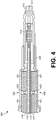
- Fig. 4 is a cross sectional view of an embodiment of a probe RF connector 400 for a flexible resistive tip cable assembly, such as flexible resistive tip cable assembly 300.
- Probe RF connector 400 is an example embodiment of probe RF connector 310.
- Probe RF connector 400 includes a signal contact 411 and a reference contact 412 structured as an RF connector positioned at the proximate end (e.g. proximate end 301) of a flexible resistive tip cable assembly.
- the RF connector is capable of coupling with an adaptor or RF receptacle, such as adaptor 120 or RF receptacle 211, and is structured to receive a differential signal.
- the signal contact 411 conducts the signal of a differential signal
- the reference contact 412 conducts the reference signal of the differential signal.
- the contacts 411-412 make up the RF connector and can be spaced as needed to embody multiple connector types, such as a Sub-Miniature Push-On (SMP) connector, a Sub-Miniature Version A (SMA) connector, a Micro-Miniature Coaxial (MMCX) connector, etc.
- SMP Sub-Miniature Push-On
- SMA Sub-Miniature Version A
- MMCX Micro-Miniature Coaxial
- the probe RF connector 400 also includes a center conductor 415 electrically coupled to the signal contact 411 and a reference conductor 417 electrically coupled to the reference contact 412.
- the center conductor 415 conducts the signal from the signal contact 411 along the coaxial cable (e.g. coaxial cable 320) and the reference conductor 417 conducts the reference signal from the reference contact 412 along the coaxial cable.
- the signal contact 411, center conductor 415, reference contact 412, and reference conductor 417 may be made of any material capable of conducting electrical signals, for example copper, copper plated steel, brass, gold, gold plated brass, etc.
- the center conductor 415 is surrounded by an insulating sleeve 416, and the reference conductor 417 surrounds the insulating sleeve 416.
- the insulating sleeve 416 is as an insulator/dielectric that keeps the center conductor 415 from electrically shorting to the reference conductor 417.
- the insulating sleeve 416 may be made of any insulating material that provides the sufficient electrical insulation for the desired task, such as polyethylene, Polytetrafluoroethylene (PTFE) (e.g. Teflon), etc.
- the probe RF connector 400 also comprises an attenuator 413.
- the attenuator 413 is electrically coupled between the center conductor 415 of the cable and the signal contact 411 of the RF connector to reduce electrical loading in the RF differential signal.
- the attenuator 413 reduces the gain associated with the differential signal, which increases the allowable input signal range of the test system (e.g. accessory 140 and/or host 150).
- the attenuator 413 also electrically isolates the test system from extraneous currents from the DUT.
- the attenuator 413 could be included in another component, such as an adaptor. As such, attenuator 413 may not be present in some embodiments.
- the center conductor 415, insulating sleeve 416, and reference conductor 417 act as a coaxial cable for conducting the differential signal.
- a plurality of magnetic elements 421 are positioned along the length of the coaxial cable.
- the magnetic elements 421 are structured to isolate the differential signal in the coaxial cable from common mode interference. Specifically, the magnetic elements 421 act as a common mode choke, which reduces common mode electromagnetic interference currents without causing signal degradation in differential signals.
- the magnetic elements 421 may be made of any suitable magnetic material, such as ferrite.
- a ferrite is a ceramic compound made of a combination of transition metals and oxygen.
- a ferrite is ferromagnetic but non-conductive.
- the magnetic elements 421 may be embodied as magnetic rings that encircle the coaxial cable.
- the coaxial cable and hence the center conductor 415, insulating sleeve 416, and reference conductor 417, has a length and a diameter.
- the magnetic elements 421 are positioned to surround the diameter of the coaxial cable along the cable's length. In some embodiments, the magnetic elements 421 directly abut the reference conductor 417.
- coaxial cable includes an insulating sleeve 418, which is substantially similar to insulating sleeve 416, that surrounds and acts as a protective layer for the reference conductor 417. In such cases, the magnetic elements 421 abut the insulating sleeve 418 surrounding the cable.
- the magnetic elements 421 are each separated from adjacent magnetic elements 421 by gaps 422.
- the gaps 422 allow the cable to bend, as a solid length of magnetic element 421 is inflexible.
- the gaps 422 are minimized to reduce the surface area of the cable without a common mode choke.
- the gaps 422 are large enough to allow the cable to bend without grinding the magnetic elements 421 together, which would damage the magnetic elements 421 over time.
- the length of the gaps 422 are about a third of the height of the magnetic elements 421 to prevent the magnetic elements 421 from rubbing together when the cable is bent.
- a plurality of elastomeric elements 423 are positioned in the gaps 422 between the magnetic elements 421.
- the elastomeric elements 423 are compressible and provide support to the cable. Specifically, the elastomeric elements 423 allow the cable to bend in a controlled manner while and prevent adjacent magnetic elements 421 from coming into contact with each other.
- An elastomeric element 423 is made of a polymer with both viscosity and elasticity. While a circular elastomeric element 423 is depicted (e.g. a spherical bead), elastomeric coatings or other shapes may also be employed.
- the probe RF connector 400 may also be partially surrounded by a protective layer 425.
- the protective layer 425 is an insulating jacket that protects the components of probe RF connector 400 and also provides additional structure to the probe RF connector 400.
- the protective layer 425 does not extend over the signal contact 411 the reference contact 412 (e.g. the RF connector), which allows the RF connector to mate with adjacent components, such as the adaptor.
- Fig. 5 is a cross sectional view of an embodiment of a coaxial cable 500 for a flexible resistive tip cable assembly, such as flexible resistive tip cable assembly 300.
- Coaxial cable 500 includes a center conductor 515, an insulating sleeve 516, a reference conductor 517, magnetic elements 521, gaps 522, elastomeric elements 523, and a protective layer 525, which are substantially similar to center conductor 415, insulating sleeve 416, reference conductor 417, magnetic elements 421, gaps 422, elastomeric elements 423, and protective layer 425, respectively.
- Coaxial cable 500 is an example embodiment of coaxial cable 320 and is structured to electrically couple a probe RF connector, such as connectors 310 and/or 400, to testing connection assembly, such as assembly 330 and/or 600.
- Coaxial cable 500 is depicted to show the magnetic elements 521 directly abutting the reference conductor 517. However, in some embodiments, the magnetic elements 521 abut an insulating sleeve surrounding the reference conductor 517 as shown in Fig. 4 .
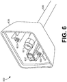
- Fig. 6 is a perspective view of an embodiment of a testing connection assembly 600 for a flexible resistive tip cable assembly, such as flexible resistive tip cable assembly 300.
- Testing connection assembly 600 is an example embodiment of a testing connection assembly 330. Testing connection assembly 600 may also be referred to as the sensor head.
- Testing connection assembly 600 includes a coaxial cable 630, which is substantially similar to coaxial cable 320 and/or 500, conducting a differential signal.
- Testing assembly 600 further includes a test RF connector 631 coupled to the coaxial cable 630 at the distal end (e.g. distal end 302) of the flexible resistive tip cable assembly.
- the test RF connector 631 is structured to electrically couple the coaxial cable 630 to an accessory and/or host, such as accessory 140 and host 150, respectively.
- the test RF connector 631 is further structured to conduct the differential signal from the DUT to the accessory/host for testing.
- the test RF connector 631 may embody multiple connector types, such as a SMP connector, a SMA connector, a MMCX connector, etc.
- Testing connection assembly 600 also includes a nose cone 635 with fasteners 633.
- Nose cone 635 is structured to couple to the accessory and/or host and be held in place via fasteners 633.
- the nose cone 635 provides safety features by preventing users from coming into contact with electrical current while the probe is in use.
- the nose cone 635 can be made of any non-conductive material suitable for safety purposes, such as plastic, rubber, or other non-conductive materials.
- the fasteners 633 are structured to hold the nose cone 635 in place during use. While threaded screws are shown, any suitable fastener may be employed as a fastener 633.
- the testing connection assembly 600 includes a memory 637, which may include an EEPROM.
- the flexible resistive tip cable assembly is tested to determine various electrical parameters of the cable assembly, the results of which are loaded into the memory 637.
- the attenuation associated with the attenuator (e.g. attenuator 413) and/or associated with the entire flexible resistive tip cable assembly is determined and loaded into the memory 637.
- the accessory/host can read the data stored in the memory 637.
- the accessory/host can then employ the stored attenuation and/or parameters during signal testing. For example, a coupled accessory may adjust a signal received via the flexible resistive tip cable assembly to account for attenuation by the attenuator, resulting in a signal of greater quality at the host without requiring user intervention.
- Examples provide a flexible resistive tip cable assembly comprising a probe Radio Frequency (RF) connector structured to receive a RF differential signal, a testing connection assembly, and a coaxial cable structured to conduct the RF differential signal between the probe RF connector and the testing connection assembly, the coaxial cable including a cable for conducting the differential signal, and a plurality of magnetic elements positioned along a length of the cable and structured to isolate the differential signal from common mode interference.
- RF Radio Frequency
- each magnetic element is separated from adjacent magnetic elements by a gap.
- the cable further includes a plurality of elastomeric elements, and wherein at least one of the elastomeric elements is positioned in each gap to provide cable flexibility.
- the plurality of magnetic elements and the elastomeric elements are positioned continuously along the length of the cable from the probe RF connector to the testing connection assembly.
- the probe RF connector includes an RF connector structured to receive the differential signal, and an attenuator electrically coupled to the probe RF connector and the cable.
- the testing connection assembly includes an Electrically Erasable Programmable Read Only Memory (EEPROM), and wherein the EEPROM includes an attenuation associated with the flexible resistive tip cable assembly for use in signal testing by a device coupled to the testing connection assembly.
- EEPROM Electrically Erasable Programmable Read Only Memory
- the plurality of magnetic elements are ferrites that each encircle the cable.
- At least one of the magnetic elements abuts a protective layer surrounding the cable.
- the cable includes a center conductor surrounded by an insulating sleeve for conducting a signal of the RF differential signal, and a reference conductor surrounding the insulating sleeve for conducting a reference signal of the RF differential signal, and wherein at least one of the magnetic elements abuts the reference conductor.
- Examples provide a cable comprising a center conductor structured to conduct a signal of a Radio Frequency (RF) differential signal, the center conductor including a length and a diameter, a reference conductor structured to conduct a reference signal of the RF differential signal, the reference conductor including a length and a diameter, a plurality of magnetic rings positioned along the length of the reference conductor and the length of the center conductor to isolate the RF differential signal from common mode interference, wherein each magnetic ring is positioned to surround the diameter of the center conductor and the diameter of the reference conductor, and wherein the magnetic rings are each separated by a gap, and a plurality of elastomeric elements positioned in the gaps between the magnetic rings.
- RF Radio Frequency
- the plurality of magnetic rings are ferrites.
- the magnetic rings abut the reference conductor.
- Some examples further comprise an insulating sleeve surrounding the center conductor, wherein the reference conductor surrounds the insulating sleeve, wherein the cable further comprises a protective layer surrounding the reference conductor, and wherein the magnetic rings abut the protective layer.
- Some examples further comprise a probe RF connector coupled to a proximate end of the cable and a test RF connector coupled to a distal end of the cable, wherein the plurality of magnetic rings and the elastomeric elements are positioned continuously along a length of the cable from the probe RF connector to the test RF connector.
- Some examples further comprise an attenuator electrically coupled to the center conductor to reduce electrical loading in the RF differential signal.
Abstract
Description
- The present application claims benefit to
U.S. Provisional Patent Application Ser. No. 62/310,164, filed March 18, 2016 U.S. Patent Application Ser. No. 15/259,818, filed September 8, 2016 - This disclosure is directed to a mechanism for signal probing, and, more particularly, to a flexible shielded probe cable for transmitting differential Radio Frequency (RF) signals for testing by a test and measurement system.
- Various systems have been developed to test differential signals from a device under test (DUT). There are a variety of ways to connect the test system to the DUT. These may include a soldered connection, RF connector, pressure contacts, wires/leads, pins, adapters, interposers, clip-ons etc. A common interface to connect the test system to the DUT is accomplished by using a pair of pins/short wires that are soldered to the differential test points, which are then connected to the test system via a cable. The problem with such systems is that ambient electric fields may interact with the cable, which may lack sufficient shielding in some cases, causing interference with the signals. Interference with both signals is referred to as common mode interference. The poorly shielded cable may experience both common mode interference and interference affecting the individual wires/leads. There is no mechanism in the cable to isolate the differential signal from the interference occurring across the cable, resulting in added signal noise that is measured by the testing system but is not present in the DUT. As such, a poorly shielded cable reduces the accuracy of test measurements taken by a testing system, particularly when measuring a differential signal with higher frequency content.
- Embodiments of the invention address these and other issues in the prior art.
- Embodiments of the disclosed subject matter include a flexible resistive tip cable assembly for differential probing. The flexible resistive tip cable assembly includes a coaxial cable structured to communicate an RF differential signal. The cable employs a plurality of magnetic elements posited along the entire length of the cable. The magnetic elements act as a distributed common mode choke. The magnetic elements are not flexible, so the magnetic elements are each separated by gaps. The gaps are filled with elastomeric elements that are compressible, which provides cable flexibility. The gaps are small to reduce the cable area without magnetic element coverage. For example, the length of the gaps may be about a third of the height of the magnetic elements to prevent the magnetic elements from rubbing together when the cable is bent. The cable includes a tip with a probe RF connector. The tip of the cable may also include an attenuator coupled to the probe RF connector to minimize/reduce the electrical loading on the signal wire. The cable also includes a testing connection assembly with a test RF connector that can be connected to a testing device. The testing connection assembly may include an Electrically Erasable Programmable Read Only Memory (EEPROM). The EEPROM is loaded with the measured attenuation of the attenuator and/or other parameters specific to the cable. In an embodiment, the testing device employs the information on the EEPROM to automatically adjust the differential signal to compensate for signal alterations occurring over the cable, resulting in a true signal at the testing device.
- Accordingly, in at least some embodiments a flexible resistive cable assembly includes a probe RF connector structured to receive a RF differential signal and a testing connection assembly. The assembly also includes a coaxial cable structured to conduct the RF differential signal between the probe RF connector and the testing connection assembly. The coaxial cable includes a cable for conducting the differential signal, and a plurality of magnetic elements positioned along a length of the cable and structured to reduce/attenuate the common mode interference in order to reduce the coupling of the common mode interference into the differential signal.
- In another aspect, in at least some embodiments a cable includes a center conductor structured to conduct a signal of a RF differential signal, the center conductor including a length and a diameter. The cable also includes a reference conductor structured to conduct a reference signal of the RF differential signal, the reference conductor including a length and a diameter. A plurality of magnetic rings are positioned along the length of the reference conductor and the length of the center conductor to reduce/attenuate the common mode interference in order to reduce the coupling of the common mode interference into the differential signal. Each magnetic ring is positioned to surround the diameter of the center conductor and the diameter of the reference conductor. The magnetic rings are each separated by a gap, and a plurality of elastomeric elements are positioned in the gaps between the magnetic rings.
-
-
Fig. 1 is a schematic diagram of an embodiment of a test and measurement system. -
Fig. 2 is a schematic diagram of another embodiment of a test and measurement system. -
Fig. 3 is a cross sectional view of an embodiment of a flexible resistive tip cable assembly for differential probing. -
Fig. 4 is a cross sectional view of an embodiment of a probe RF connector for a flexible resistive tip cable assembly. -
Fig. 5 is a cross sectional view of an embodiment of a coaxial cable for a flexible resistive tip cable assembly. -
Fig. 6 is a perspective view of an embodiment of a testing connection assembly for a flexible resistive tip cable assembly. - As described herein, the embodiments of the disclosure are directed to a flexible resistive tip cable assembly for differential probing. The flexible resistive tip cable assembly, also known as a probe, includes a coaxial cable for conducting a differential signal. The cable is surrounded by a plurality of magnetic elements, which may be structured as rings. The magnetic elements act as a common mode choke. The magnetic elements are separated by gaps, which are filled with elastomeric elements. The elastomeric elements generally maintain spacing between the magnetic elements, but are compressible allowing the cable to bend. The probe may also include an attenuator to minimize/reduce electrical loading on the signal wire and promote signal isolation. Further, the probe may also include a memory that stores the attenuation of the attenuator as well as other tested parameters associated with the probe. Devices attached to the probe may use the stored data to compensate for signal alterations occurring in the probe. Accordingly, the probe provides an environment where the differential signal is highly shielded and alterations to the signal are pre-compensated, allowing the signal received by the testing device to mirror the signal in the DUT to a very high degree of accuracy.
-
Fig. 1 is a schematic diagram of an embodiment of a test andmeasurement system 100.System 100 includes aDUT 110 with a pair ofdifferential pins 111.Differential signals 161 from thedifferential pins 111 are sent to thehost 150 for testing. Thedifferential signals 161 encode information as the difference between a signal traversing thesignal pin 111a and a reference signal traversing thereference pin 111b. Thehost 150 is configured to receivedifferential signals 161. Anadaptor 120 conducts signals traversing the two pins/leads into a coaxial connection to be sent to thehost 150. Thedifferential signals 161 are sent to thehost 150 via aprobe 130 and, in some embodiments, anaccessory 140 that acts a controller and/or pre-processor for thehost 150. - A
DUT 110 is any device structured to generatedifferential signals 161 for testing. For example, aDUT 110 may include a circuit board with any differential signals. These differential signals may be for transmission of data, controlling or biasing power supplies, high voltage signaling, or employed in other transmission systems etc. One of ordinary skill in the art will appreciate that aDUT 110 employing differential signaling encompasses a wide range for devices and the examples provided herein are included for purposes of explanation and should not be considered limiting. TheDUT 110 includesdifferential pair 111 which are a pair of output pins that can be used to tap into the differential signal in theDUT 110 for testing purposes. Thedifferential pair 111 include asignal pin 111a and areference pin 111b. Thedifferential signal 161 is a signal encoded as the difference between the signal traversing thesignal pin 111a and the reference signal traversing thereference pin 111b. -
Adaptor 120 is a differential connector to RF adaptor and is hence a device structured to interface between the pins/leads from the DUT's test points and a controlled impedance coaxial connection.Adaptor 120 is structured to interface with the pins/leads ofdifferential pair 111 and transmit thedifferential signal 161 to probe 130. Specifically,adaptor 120 includes a pair of contacts that connect to an RF connector. The RF connector is selected to interface with theprobe 130. The central contact of theadapter 120, which connects to thesignal pin 111a, is connected to the center pin contact of the RF connector. Further, theadaptor 120 includes a reference contact, which connects to thereference pin 111b, and is connected to the outer shield contact of the RF connector. Theadaptor 120 is further structured to abut theDUT 110 when interfacing with thedifferential pair 111 in order to shield/isolate thedifferential signals 161 from common mode or other ambient electrical interference occurring between theDUT 110 and the RF connector. Theadaptor 120 is further structured to provide physical support for thedifferential pair 111. Specifically, theadaptor 120 maintains thedifferential pair 111 in a controlled position relative to each other and relative to RF connector and a corresponding coaxial connection, causing the entire connection to maintain a controlled impedance. Theadaptor 120 may also include securing elements structured to securereference pin 111b to the reference contact and/or to secure thesignal pin 111a to the central contact. Theadaptor 120 also includes a protective layer structured to protect theadaptor 120 and the coupleddifferential pair 111 during use. Theadaptor 120 may or may not be soldered to thedifferential pair 111. Thedifferential pair 111 may employ round or square pins or short wire leads, and theadaptor 120 is structured accordingly to engage with the pins/leads as needed. In some embodiments, theadaptor 120 includes an attenuator between the central and/or reference contacts and the RF connector to adjust the gain of thedifferential signals 161 to increase the acceptable input signal range and to better electrically isolate theDUT 110 system from thehost 150. -
Probe 130 is device structured to couple toadaptor 120 at the RF connector and communicate thedifferential signals 161 towardaccessory 140.Probe 130 includes a coaxial cable with a probe RF connector to mate with the adaptor's RF connector. Specifically, probe 130 contains a coaxial cable with a center conductor and an outer shield.Probe 130 may also be constructed using a twisted pair and may be shielded. In some embodiments, theprobe 130 includes an attenuator (e.g. if adaptor does not employ an attenuator). Further, theprobe 130 includes a plurality of magnetic elements (e.g. ferrites) surrounding the coaxial cable and spaced along the length of the cable. The ferrites reduce common mode interference. The magnetic elements are separated by gaps, which are filled with elastomeric elements. The elastomeric elements are compressible, which allows the probe to bend and prevent adjacent magnetic elements from pressing together (e.g. reducing wear and preventing stress fractures). Theprobe 130 is structured to couple to, and propagate thedifferential signals 161 toaccessory 140. In some embodiments, theprobe 130 also includes anEEPROM containing probe 130 specifications, for example the resistance in the probe tip, tip attenuation, frequency response, and/or other parameters specific to probe 130. -
Accessory 140 is any device structured to sense and/or precondition thedifferential signals 161 forhost 150. Theaccessory 140 may include a sensor head for sensing thedifferential signals 161, a controller for preconditioning thedifferential signals 161, or combinations thereof. For example, theaccessory 140 may obtain information from the EEPROM to adjust the gain of thesignals 161 to compensate for losses naturally occurring when thedifferential signals 161 traverse theprobe 130.Accessory 140 is designed to deliver thedifferential signals 161 to thehost 150 while maintaining substantially the same electrical properties as the differential signals 161. Specifically, theaccessory 140 is designed to minimize noise injected into thesignals 161 while traversing thedifferential pair 111,adaptor 120, and probe 130. -
Host 150 is structured to couple toaccessory 140 and receive thesignals 161 for testing and/or measurement. For example, host 150 is an oscilloscope or other test system.Host 150 receives thedifferential signals 161 from theaccessory 140 and may display them on a graticule for a user. Host 150 may also capture characteristics from thedifferential signals 161 in memory for further calculation and use by the user. Accordingly, theadaptor 120,probe 130, andaccessory 140 are employed to allow the user to measuredifferential signals 161 that are substantially identical to thedifferential signals 161 obtained from theDUT 110. -
Fig. 2 is a schematic diagram of another embodiment of a test andmeasurement system 200, which is similar tosystem 100.System 200 includes aDUT 210, aprobe 230, anaccessory 240, and ahost 250 structured to conductdifferential signals 261, which are substantially similar toDUT 110,probe 130,accessory 140,host 150, anddifferential signals 161, respectively. Unlikesystem 100,DUT 210 includes amating RF receptacle 211 instead ofdifferential pair 111. TheRF receptacle 211 includes a coaxial connector for conducting a differential signal and is structured to coupled directly withprobe 230 without the need of an intervening adaptor. Accordingly, probe 230 can be employed without the use of an adaptor such asadaptor 120. -
Fig. 3 is a cross sectional view of an embodiment of a flexible resistivetip cable assembly 300 for differential probing (e.g. a probe with a probe tip). Thecable assembly 300 is an example embodiment of theprobe 130. Thecable assembly 300 includes aprobe RF connector 310, acoaxial cable 320, and atesting connection assembly 330. Theprobe RF connector 310 is positioned at aproximate end 301 of thecable assembly 300 and thetesting connection assembly 330 is positioned at adistal end 302 of thecable assembly 300. Theprobe RF connector 310 is electrically coupled to thetesting connection assembly 330 via thecoaxial cable 320. Theprobe RF connector 310 is further configured to couple to an adaptor or RF receptacle, such asadaptor 120 orRF receptacle 211. Accordingly, theprobe RF connector 310 is structured to receive a RF differential signal, such as adifferential signal 161, from an adaptor, and thecoaxial cable 320 is structured to conduct the RF differential signal between theprobe RF connector 310 and thetesting connection assembly 330. Thetesting connection assembly 330 is structured to couple to a testing device, such asaccessory 140 and/orhost 150. As such, the RF differential signal can be conducted from the adaptor to the accessory/host via the flexible resistivetip cable assembly 300. The flexible resistivetip cable assembly 300 employs magnetic elements, such as ferrites, positioned along thecoaxial cable 320 to reduce/attenuate the common mode interference from coupling into the differential signal. Complete enclosure in magnetic elements would render thecable 320 rigid, so small gaps are positioned between the magnetic elements to allow forcable 320 movement. In some embodiments, compressible elastomeric elements are positioned in the gaps to allow forflexible cable 320 movement and prevent grinding of the magnetic elements during use. The magnetic elements and the elastomeric elements may be positioned continuously along a length of thecable 320 from theprobe RF connector 310 to a test RF connector in thetesting connection assembly 330 for maximum rejection of the common mode interference. Example embodiments of components suitable for use in the flexible resistivetip cable assembly 300 are discussed more fully below. -
Fig. 4 is a cross sectional view of an embodiment of aprobe RF connector 400 for a flexible resistive tip cable assembly, such as flexible resistivetip cable assembly 300.Probe RF connector 400 is an example embodiment ofprobe RF connector 310.Probe RF connector 400 includes asignal contact 411 and areference contact 412 structured as an RF connector positioned at the proximate end (e.g. proximate end 301) of a flexible resistive tip cable assembly. The RF connector is capable of coupling with an adaptor or RF receptacle, such asadaptor 120 orRF receptacle 211, and is structured to receive a differential signal. Thesignal contact 411 conducts the signal of a differential signal, and thereference contact 412 conducts the reference signal of the differential signal. The contacts 411-412 make up the RF connector and can be spaced as needed to embody multiple connector types, such as a Sub-Miniature Push-On (SMP) connector, a Sub-Miniature Version A (SMA) connector, a Micro-Miniature Coaxial (MMCX) connector, etc. - The
probe RF connector 400 also includes acenter conductor 415 electrically coupled to thesignal contact 411 and areference conductor 417 electrically coupled to thereference contact 412. Thecenter conductor 415 conducts the signal from thesignal contact 411 along the coaxial cable (e.g. coaxial cable 320) and thereference conductor 417 conducts the reference signal from thereference contact 412 along the coaxial cable. Thesignal contact 411,center conductor 415,reference contact 412, andreference conductor 417 may be made of any material capable of conducting electrical signals, for example copper, copper plated steel, brass, gold, gold plated brass, etc. Thecenter conductor 415 is surrounded by an insulatingsleeve 416, and thereference conductor 417 surrounds the insulatingsleeve 416. The insulatingsleeve 416 is as an insulator/dielectric that keeps thecenter conductor 415 from electrically shorting to thereference conductor 417. The insulatingsleeve 416 may be made of any insulating material that provides the sufficient electrical insulation for the desired task, such as polyethylene, Polytetrafluoroethylene (PTFE) (e.g. Teflon), etc. - The
probe RF connector 400 also comprises anattenuator 413. Theattenuator 413 is electrically coupled between thecenter conductor 415 of the cable and thesignal contact 411 of the RF connector to reduce electrical loading in the RF differential signal. Theattenuator 413 reduces the gain associated with the differential signal, which increases the allowable input signal range of the test system (e.g. accessory 140 and/or host 150). Theattenuator 413 also electrically isolates the test system from extraneous currents from the DUT. In some embodiments, theattenuator 413 could be included in another component, such as an adaptor. As such,attenuator 413 may not be present in some embodiments. - The
center conductor 415, insulatingsleeve 416, andreference conductor 417 act as a coaxial cable for conducting the differential signal. A plurality ofmagnetic elements 421 are positioned along the length of the coaxial cable. Themagnetic elements 421 are structured to isolate the differential signal in the coaxial cable from common mode interference. Specifically, themagnetic elements 421 act as a common mode choke, which reduces common mode electromagnetic interference currents without causing signal degradation in differential signals. Themagnetic elements 421 may be made of any suitable magnetic material, such as ferrite. A ferrite is a ceramic compound made of a combination of transition metals and oxygen. A ferrite is ferromagnetic but non-conductive. Themagnetic elements 421 may be embodied as magnetic rings that encircle the coaxial cable. Specifically, the coaxial cable, and hence thecenter conductor 415, insulatingsleeve 416, andreference conductor 417, has a length and a diameter. Themagnetic elements 421 are positioned to surround the diameter of the coaxial cable along the cable's length. In some embodiments, themagnetic elements 421 directly abut thereference conductor 417. In other embodiments, coaxial cable includes an insulatingsleeve 418, which is substantially similar to insulatingsleeve 416, that surrounds and acts as a protective layer for thereference conductor 417. In such cases, themagnetic elements 421 abut the insulatingsleeve 418 surrounding the cable. - The
magnetic elements 421 are each separated from adjacentmagnetic elements 421 bygaps 422. Thegaps 422 allow the cable to bend, as a solid length ofmagnetic element 421 is inflexible. Thegaps 422 are minimized to reduce the surface area of the cable without a common mode choke. However, thegaps 422 are large enough to allow the cable to bend without grinding themagnetic elements 421 together, which would damage themagnetic elements 421 over time. In an example embodiment, the length of thegaps 422 are about a third of the height of themagnetic elements 421 to prevent themagnetic elements 421 from rubbing together when the cable is bent. - In some embodiments, a plurality of
elastomeric elements 423 are positioned in thegaps 422 between themagnetic elements 421. Theelastomeric elements 423 are compressible and provide support to the cable. Specifically, theelastomeric elements 423 allow the cable to bend in a controlled manner while and prevent adjacentmagnetic elements 421 from coming into contact with each other. Anelastomeric element 423 is made of a polymer with both viscosity and elasticity. While a circularelastomeric element 423 is depicted (e.g. a spherical bead), elastomeric coatings or other shapes may also be employed. - The
probe RF connector 400 may also be partially surrounded by aprotective layer 425. Theprotective layer 425 is an insulating jacket that protects the components ofprobe RF connector 400 and also provides additional structure to theprobe RF connector 400. Theprotective layer 425 does not extend over thesignal contact 411 the reference contact 412 (e.g. the RF connector), which allows the RF connector to mate with adjacent components, such as the adaptor. -
Fig. 5 is a cross sectional view of an embodiment of acoaxial cable 500 for a flexible resistive tip cable assembly, such as flexible resistivetip cable assembly 300.Coaxial cable 500 includes a center conductor 515, an insulatingsleeve 516, areference conductor 517,magnetic elements 521,gaps 522,elastomeric elements 523, and aprotective layer 525, which are substantially similar tocenter conductor 415, insulatingsleeve 416,reference conductor 417,magnetic elements 421,gaps 422,elastomeric elements 423, andprotective layer 425, respectively.Coaxial cable 500 is an example embodiment ofcoaxial cable 320 and is structured to electrically couple a probe RF connector, such asconnectors 310 and/or 400, to testing connection assembly, such asassembly 330 and/or 600.Coaxial cable 500 is depicted to show themagnetic elements 521 directly abutting thereference conductor 517. However, in some embodiments, themagnetic elements 521 abut an insulating sleeve surrounding thereference conductor 517 as shown inFig. 4 . -
Fig. 6 is a perspective view of an embodiment of atesting connection assembly 600 for a flexible resistive tip cable assembly, such as flexible resistivetip cable assembly 300.Testing connection assembly 600 is an example embodiment of atesting connection assembly 330.Testing connection assembly 600 may also be referred to as the sensor head.Testing connection assembly 600 includes acoaxial cable 630, which is substantially similar tocoaxial cable 320 and/or 500, conducting a differential signal.Testing assembly 600 further includes atest RF connector 631 coupled to thecoaxial cable 630 at the distal end (e.g. distal end 302) of the flexible resistive tip cable assembly. Thetest RF connector 631 is structured to electrically couple thecoaxial cable 630 to an accessory and/or host, such asaccessory 140 andhost 150, respectively. Thetest RF connector 631 is further structured to conduct the differential signal from the DUT to the accessory/host for testing. Thetest RF connector 631 may embody multiple connector types, such as a SMP connector, a SMA connector, a MMCX connector, etc. -
Testing connection assembly 600 also includes anose cone 635 withfasteners 633.Nose cone 635 is structured to couple to the accessory and/or host and be held in place viafasteners 633. Thenose cone 635 provides safety features by preventing users from coming into contact with electrical current while the probe is in use. Thenose cone 635 can be made of any non-conductive material suitable for safety purposes, such as plastic, rubber, or other non-conductive materials. Thefasteners 633 are structured to hold thenose cone 635 in place during use. While threaded screws are shown, any suitable fastener may be employed as afastener 633. - In some embodiments, the
testing connection assembly 600 includes amemory 637, which may include an EEPROM. During manufacture, the flexible resistive tip cable assembly is tested to determine various electrical parameters of the cable assembly, the results of which are loaded into thememory 637. In one embodiment, the attenuation associated with the attenuator (e.g. attenuator 413) and/or associated with the entire flexible resistive tip cable assembly is determined and loaded into thememory 637. When thetesting connection assembly 600 is coupled to the accessory/host, the accessory/host can read the data stored in thememory 637. The accessory/host can then employ the stored attenuation and/or parameters during signal testing. For example, a coupled accessory may adjust a signal received via the flexible resistive tip cable assembly to account for attenuation by the attenuator, resulting in a signal of greater quality at the host without requiring user intervention. - Examples provide a flexible resistive tip cable assembly comprising a probe Radio Frequency (RF) connector structured to receive a RF differential signal, a testing connection assembly, and a coaxial cable structured to conduct the RF differential signal between the probe RF connector and the testing connection assembly, the coaxial cable including a cable for conducting the differential signal, and a plurality of magnetic elements positioned along a length of the cable and structured to isolate the differential signal from common mode interference.
- In some examples, each magnetic element is separated from adjacent magnetic elements by a gap.
- In some examples, the cable further includes a plurality of elastomeric elements, and wherein at least one of the elastomeric elements is positioned in each gap to provide cable flexibility.
- In some examples, the plurality of magnetic elements and the elastomeric elements are positioned continuously along the length of the cable from the probe RF connector to the testing connection assembly.
- In some examples, the probe RF connector includes an RF connector structured to receive the differential signal, and an attenuator electrically coupled to the probe RF connector and the cable.
- In some examples the testing connection assembly includes an Electrically Erasable Programmable Read Only Memory (EEPROM), and wherein the EEPROM includes an attenuation associated with the flexible resistive tip cable assembly for use in signal testing by a device coupled to the testing connection assembly.
- In some examples, the plurality of magnetic elements are ferrites that each encircle the cable.
- In some examples, at least one of the magnetic elements abuts a protective layer surrounding the cable.
- In some examples, the cable includes a center conductor surrounded by an insulating sleeve for conducting a signal of the RF differential signal, and a reference conductor surrounding the insulating sleeve for conducting a reference signal of the RF differential signal, and wherein at least one of the magnetic elements abuts the reference conductor.
- Examples provide a cable comprising a center conductor structured to conduct a signal of a Radio Frequency (RF) differential signal, the center conductor including a length and a diameter, a reference conductor structured to conduct a reference signal of the RF differential signal, the reference conductor including a length and a diameter, a plurality of magnetic rings positioned along the length of the reference conductor and the length of the center conductor to isolate the RF differential signal from common mode interference, wherein each magnetic ring is positioned to surround the diameter of the center conductor and the diameter of the reference conductor, and wherein the magnetic rings are each separated by a gap, and a plurality of elastomeric elements positioned in the gaps between the magnetic rings.
- In some examples the plurality of magnetic rings are ferrites.
- In some examples, the magnetic rings abut the reference conductor.
- Some examples further comprise an insulating sleeve surrounding the center conductor, wherein the reference conductor surrounds the insulating sleeve, wherein the cable further comprises a protective layer surrounding the reference conductor, and wherein the magnetic rings abut the protective layer.
- Some examples further comprise a probe RF connector coupled to a proximate end of the cable and a test RF connector coupled to a distal end of the cable, wherein the plurality of magnetic rings and the elastomeric elements are positioned continuously along a length of the cable from the probe RF connector to the test RF connector.
- Some examples further comprise an attenuator electrically coupled to the center conductor to reduce electrical loading in the RF differential signal.
- The previously described versions of the disclosed subject matter have many advantages that were either described or would be apparent to a person of ordinary skill. Even so, all of these advantages or features are not required in all versions of the disclosed apparatus, systems, or methods.
- Additionally, this written description makes reference to particular features. It is to be understood that the disclosure in this specification includes all possible combinations of those particular features. For example, where a particular feature is disclosed in the context of a particular aspect or embodiment, that feature can also be used, to the extent possible, in the context of other aspects and embodiments.
- Also, when reference is made in this application to a method having two or more defined steps or operations, the defined steps or operations can be carried out in any order or simultaneously, unless the context excludes those possibilities.
- Although specific embodiments of the invention have been illustrated and described for purposes of illustration, it will be understood that various modifications may be made without departing from the scope of the invention. Accordingly, the invention should not be limited except as by the appended claims.
Claims (15)
- A flexible resistive tip cable assembly comprising:a probe Radio Frequency (RF) connector structured to receive a RF differential signal;a testing connection assembly; anda coaxial cable structured to conduct the RF differential signal between the probe RF connector and the testing connection assembly, the coaxial cable including:a cable for conducting the differential signal, anda plurality of magnetic elements positioned along a length of the cable and structured to isolate the differential signal from common mode interference.
- The cable assembly of claim 1, wherein each magnetic element is separated from adjacent magnetic elements by a gap.
- The cable assembly of claim 2, wherein the cable further includes a plurality of elastomeric elements, and wherein at least one of the elastomeric elements is positioned in each gap to provide cable flexibility.
- The cable assembly of claim 3, wherein the plurality of magnetic elements and the elastomeric elements are positioned continuously along the length of the cable from the probe RF connector to the testing connection assembly.
- The cable assembly of any of claims 1 to 4, wherein the probe RF connector includes:an RF connector structured to receive the differential signal, andan attenuator electrically coupled to the probe RF connector and the cable.
- The cable assembly of any of claims 1 to 5, wherein the testing connection assembly includes an Electrically Erasable Programmable Read Only Memory (EEPROM), and wherein the EEPROM includes an attenuation associated with the flexible resistive tip cable assembly for use in signal testing by a device coupled to the testing connection assembly.
- The cable assembly of any of claims 1 to 6, wherein the plurality of magnetic elements are ferrites that each encircle the cable.
- The cable assembly of any of claims 1 to 7, wherein at least one of the magnetic elements abuts a protective layer surrounding the cable.
- The cable assembly of any of claims 1 to 8, wherein the cable includes
a center conductor surrounded by an insulating sleeve for conducting a signal of the RF differential signal, and
a reference conductor surrounding the insulating sleeve for conducting a reference signal of the RF differential signal, and
wherein at least one of the magnetic elements abuts the reference conductor. - A cable comprising:a center conductor structured to conduct a signal of a Radio Frequency (RF) differential signal, the center conductor including a length and a diameter;a reference conductor structured to conduct a reference signal of the RF differential signal, the reference conductor including a length and a diameter;a plurality of magnetic rings positioned along the length of the reference conductor and the length of the center conductor to isolate the RF differential signal from common mode interference, wherein each magnetic ring is positioned to surround the diameter of the center conductor and the diameter of the reference conductor, and wherein the magnetic rings are each separated by a gap; anda plurality of elastomeric elements positioned in the gaps between the magnetic rings.
- The cable of claim 10, wherein the plurality of magnetic rings are ferrites.
- The cable of claim 10 or 11, wherein the magnetic rings abut the reference conductor.
- The cable of any of claims 10 to 12, further comprising an insulating sleeve surrounding the center conductor, wherein the reference conductor surrounds the insulating sleeve, wherein the cable further comprises a protective layer surrounding the reference conductor, and wherein the magnetic rings abut the protective layer.
- The cable of any of claims 10 to 13, further comprising a probe RF connector coupled to a proximate end of the cable and a test RF connector coupled to a distal end of the cable, wherein the plurality of magnetic rings and the elastomeric elements are positioned continuously along a length of the cable from the probe RF connector to the test RF connector.
- The cable of any of claims 10 to 14, further comprising an attenuator electrically coupled to the center conductor to reduce electrical loading in the RF differential signal.
Applications Claiming Priority (2)
| Application Number | Priority Date | Filing Date | Title |
|---|---|---|---|
| US201662310164P | 2016-03-18 | 2016-03-18 | |
| US15/259,818 US10302676B2 (en) | 2016-03-18 | 2016-09-08 | Flexible resistive tip cable assembly for differential probing |
Publications (1)
| Publication Number | Publication Date |
|---|---|
| EP3220154A1 true EP3220154A1 (en) | 2017-09-20 |
Family
ID=58358509
Family Applications (1)
| Application Number | Title | Priority Date | Filing Date |
|---|---|---|---|
| EP17161687.3A Pending EP3220154A1 (en) | 2016-03-18 | 2017-03-17 | Flexible resistive tip cable assembly for differential probing |
Country Status (4)
| Country | Link |
|---|---|
| US (1) | US10302676B2 (en) |
| EP (1) | EP3220154A1 (en) |
| JP (1) | JP2017173324A (en) |
| CN (2) | CN116487962A (en) |
Families Citing this family (4)
| Publication number | Priority date | Publication date | Assignee | Title |
|---|---|---|---|---|
| DE102017222809B4 (en) * | 2017-12-14 | 2019-10-02 | Micro-Epsilon Messtechnik Gmbh & Co. Kg | Electrical connector and connector |
| US20220349917A1 (en) | 2021-04-29 | 2022-11-03 | Tektronix, Inc. | Isolated probe tip |
| US11705611B2 (en) * | 2021-05-20 | 2023-07-18 | Ryan Letcher | High-frequency coaxial attenuator |
| US11733266B2 (en) | 2021-07-21 | 2023-08-22 | Rohde & Schwarz Gmbh & Co. Kg | Probe cable assembly and method |
Citations (4)
| Publication number | Priority date | Publication date | Assignee | Title |
|---|---|---|---|---|
| EP1030182A1 (en) * | 1999-02-18 | 2000-08-23 | STMicroelectronics | Calibrating a RF integrated circuit sensor |
| US20080012591A1 (en) * | 2006-06-09 | 2008-01-17 | Richard Campbell | Differential signal probe with integral balun |
| DE102012207341A1 (en) * | 2012-05-03 | 2013-11-07 | Rohde & Schwarz Gmbh & Co. Kg | Ultrabroadband bridge |
| EP2750150A1 (en) * | 2012-12-28 | 2014-07-02 | Hitachi Metals, Ltd. | Wire harness |
Family Cites Families (14)
| Publication number | Priority date | Publication date | Assignee | Title |
|---|---|---|---|---|
| FR2461342A1 (en) * | 1979-07-06 | 1981-01-30 | Mayer Ferdy | HIGH IMMUNITY CABLES, AGAINST ELECTROMAGNETIC PULSE (EMP) |
| US4267529A (en) * | 1980-02-11 | 1981-05-12 | Gte Products Corporation | TV antenna isolation system |
| JPS5923259A (en) * | 1982-07-30 | 1984-02-06 | Hitachi Ltd | Protecting chip for attenuator |
| JP2513289Y2 (en) * | 1990-11-28 | 1996-10-02 | 太陽誘電株式会社 | Electromagnetic interference removal filter |
| US6469594B1 (en) * | 1999-01-05 | 2002-10-22 | Audio Prism, Inc. | Attenuation of electromagnetic noise including a permanent magnet |
| US20050275565A1 (en) * | 2003-01-23 | 2005-12-15 | Daniel Nachtigal | Magnetizable polymeric compositions |
| JP2004227948A (en) * | 2003-01-23 | 2004-08-12 | Yokowo Co Ltd | Coaxial connector |
| JP5080459B2 (en) * | 2005-06-13 | 2012-11-21 | カスケード マイクロテック インコーポレイテッド | Wideband active / passive differential signal probe |
| US7294995B1 (en) * | 2006-05-08 | 2007-11-13 | Tektronix, Inc. | Current probing system |
| US7595646B2 (en) * | 2006-10-04 | 2009-09-29 | Dell Products L.P. | System and method for information handling system peripheral EMC test |
| JP5243946B2 (en) * | 2008-12-24 | 2013-07-24 | モレックス インコーポレイテド | Coaxial connector |
| US9304150B2 (en) * | 2011-09-30 | 2016-04-05 | Keysight Technologies, Inc. | Closed core current probe |
| US10067165B2 (en) * | 2015-09-04 | 2018-09-04 | Ford Global Technologies, Llc | Isolated differential voltage probe for EMI noise source |
| CN105305189B (en) * | 2015-11-18 | 2018-07-06 | 成都雷电微力科技有限公司 | A kind of molding of wave control more than one point cable |
-
2016
- 2016-09-08 US US15/259,818 patent/US10302676B2/en active Active
-
2017
- 2017-03-17 CN CN202310579648.8A patent/CN116487962A/en active Pending
- 2017-03-17 CN CN201710281866.8A patent/CN107359491B/en active Active
- 2017-03-17 EP EP17161687.3A patent/EP3220154A1/en active Pending
- 2017-03-21 JP JP2017054951A patent/JP2017173324A/en active Pending
Patent Citations (4)
| Publication number | Priority date | Publication date | Assignee | Title |
|---|---|---|---|---|
| EP1030182A1 (en) * | 1999-02-18 | 2000-08-23 | STMicroelectronics | Calibrating a RF integrated circuit sensor |
| US20080012591A1 (en) * | 2006-06-09 | 2008-01-17 | Richard Campbell | Differential signal probe with integral balun |
| DE102012207341A1 (en) * | 2012-05-03 | 2013-11-07 | Rohde & Schwarz Gmbh & Co. Kg | Ultrabroadband bridge |
| EP2750150A1 (en) * | 2012-12-28 | 2014-07-02 | Hitachi Metals, Ltd. | Wire harness |
Also Published As
| Publication number | Publication date |
|---|---|
| CN107359491B (en) | 2023-06-09 |
| JP2017173324A (en) | 2017-09-28 |
| US20170271826A1 (en) | 2017-09-21 |
| CN116487962A (en) | 2023-07-25 |
| CN107359491A (en) | 2017-11-17 |
| US10302676B2 (en) | 2019-05-28 |
Similar Documents
| Publication | Publication Date | Title |
|---|---|---|
| US10302676B2 (en) | Flexible resistive tip cable assembly for differential probing | |
| EP3220491B1 (en) | Differential pin to rf adaptor for probing applications | |
| JP4014851B2 (en) | Cable assembly | |
| US5982187A (en) | Resilient connector having a tubular spring | |
| US6724205B1 (en) | Probe for combined signals | |
| JP2006329992A (en) | Differential measuring probe | |
| JP2001099889A (en) | Inspection equipment for high frequency circuit | |
| JPH1038914A (en) | Connecting device of apparatus to test lead | |
| US20070222468A1 (en) | High bandwidth probe system | |
| US6841986B1 (en) | Inductively coupled direct contact test probe | |
| TWI700500B (en) | Test device | |
| US9651576B2 (en) | Low-side coaxial current probe | |
| Hähner et al. | History and recent trends of Triaxial test procedure | |
| CN113514780B (en) | Test system and test method for satellite whole-satellite low-frequency cable | |
| US20030222665A1 (en) | Voltage probe systems having improved bandwidth capability | |
| US20040189276A1 (en) | Systems and methods for making a high-bandwidth coaxial cable connection | |
| JP3214259U (en) | Connector for cable tester cord | |
| US11733266B2 (en) | Probe cable assembly and method | |
| WO2018182703A1 (en) | Integrated cable probe design for high bandwidth rf testing | |
| EP3001209A1 (en) | Dc-ac connection system comprising triaxial cables | |
| US11035881B2 (en) | Probe, measuring system as well as test setup | |
| JP2022008080A (en) | Current measurement component, current measurement device, and current measurement method | |
| GB2336948A (en) | BNC test connector | |
| JPS6221064A (en) | Spring-contact type probe | |
| EP3534163A1 (en) | Probe with broadband antenna |
Legal Events
| Date | Code | Title | Description |
|---|---|---|---|
| PUAI | Public reference made under article 153(3) epc to a published international application that has entered the european phase |
Free format text: ORIGINAL CODE: 0009012 |
|
| STAA | Information on the status of an ep patent application or granted ep patent |
Free format text: STATUS: THE APPLICATION HAS BEEN PUBLISHED |
|
| AK | Designated contracting states |
Kind code of ref document: A1 Designated state(s): AL AT BE BG CH CY CZ DE DK EE ES FI FR GB GR HR HU IE IS IT LI LT LU LV MC MK MT NL NO PL PT RO RS SE SI SK SM TR |
|
| AX | Request for extension of the european patent |
Extension state: BA ME |
|
| STAA | Information on the status of an ep patent application or granted ep patent |
Free format text: STATUS: REQUEST FOR EXAMINATION WAS MADE |
|
| 17P | Request for examination filed |
Effective date: 20180319 |
|
| RBV | Designated contracting states (corrected) |
Designated state(s): AL AT BE BG CH CY CZ DE DK EE ES FI FR GB GR HR HU IE IS IT LI LT LU LV MC MK MT NL NO PL PT RO RS SE SI SK SM TR |
|
| STAA | Information on the status of an ep patent application or granted ep patent |
Free format text: STATUS: EXAMINATION IS IN PROGRESS |
|
| RIC1 | Information provided on ipc code assigned before grant |
Ipc: G01R 1/067 20060101AFI20210614BHEP Ipc: G01R 1/18 20060101ALN20210614BHEP |
|
| 17Q | First examination report despatched |
Effective date: 20210624 |
|
| STAA | Information on the status of an ep patent application or granted ep patent |
Free format text: STATUS: EXAMINATION IS IN PROGRESS |
|
| GRAP | Despatch of communication of intention to grant a patent |
Free format text: ORIGINAL CODE: EPIDOSNIGR1 |
|
| STAA | Information on the status of an ep patent application or granted ep patent |
Free format text: STATUS: GRANT OF PATENT IS INTENDED |
|
| RIC1 | Information provided on ipc code assigned before grant |
Ipc: G01R 1/18 20060101ALI20231110BHEP Ipc: G01R 1/067 20060101AFI20231110BHEP |
|
| INTG | Intention to grant announced |
Effective date: 20231201 |
|
| GRAS | Grant fee paid |
Free format text: ORIGINAL CODE: EPIDOSNIGR3 |
|
| GRAA | (expected) grant |
Free format text: ORIGINAL CODE: 0009210 |
|
| STAA | Information on the status of an ep patent application or granted ep patent |
Free format text: STATUS: THE PATENT HAS BEEN GRANTED |