US10440A - Bailroad-cie - Google Patents
Bailroad-cie Download PDFInfo
- Publication number
- US10440A US10440A US10440DA US10440A US 10440 A US10440 A US 10440A US 10440D A US10440D A US 10440DA US 10440 A US10440 A US 10440A
- Authority
- US
- United States
- Prior art keywords
- bars
- levers
- vibrating
- attached
- standards
- Prior art date
- Legal status (The legal status is an assumption and is not a legal conclusion. Google has not performed a legal analysis and makes no representation as to the accuracy of the status listed.)
- Expired - Lifetime
Links
- UIIMBOGNXHQVGW-UHFFFAOYSA-M buffer Substances [Na+].OC([O-])=O UIIMBOGNXHQVGW-UHFFFAOYSA-M 0.000 description 8
- 238000010276 construction Methods 0.000 description 6
- 230000000875 corresponding Effects 0.000 description 6
- 229910052760 oxygen Inorganic materials 0.000 description 4
- 229910052717 sulfur Inorganic materials 0.000 description 4
- 235000013372 meat Nutrition 0.000 description 2
Images

Classifications
-
- B—PERFORMING OPERATIONS; TRANSPORTING
- B61—RAILWAYS
- B61H—BRAKES OR OTHER RETARDING DEVICES SPECIALLY ADAPTED FOR RAIL VEHICLES; ARRANGEMENT OR DISPOSITION THEREOF IN RAIL VEHICLES
- B61H13/00—Actuating rail vehicle brakes
- B61H13/02—Hand or other personal actuation
Definitions
- FIG. 1 is an enlarged view of a portion Fig.2, v
- the natureof my invention consists in causing the shoes to act upon the wheels by means of levers attached to vibrating bars which have each a revolving vertical standard upon them surmounted by a hand wheel.
- a vibrating rod or bar is placed at each end of the platform of the car.
- the vertical standards are connected by a chain, and as either of the standards abovementioned are turned the chain is moved upon it and the vibrating bars brought nearer together, the bar acting upon the levers above mentioned and causing the shoes to act upon the wheels. as will be hereafter more fully described.
- the vibrating bars being forced back to their original position by springs.
- Two levers, one on each vibrating bar, are connected by cross rods or chains, so that with the aid of adjustable levers, which will be fully shown and explained hereafter, the bufler rods will act upon the vibrating bars and consequently the shoes upon the wheels in a greater or less time as desired.
- A represents the platform of a car and B, B, are trucks of ordinary construction attached to the platform in the usual way.
- C, C are vibrating bars attached to the under sides of the cross pieces (a) of the platform. See Fig. 3.
- These bars C, C have slots (1)) in them a slot being at each end of the bars 'and a screw (0) passes through each slot into the cross'pieces (a) the heads of the screws retaining the bars 0, (3,, against the cross pieces (a). By this means the bars are allowed to vibrate the length of the slots.
- G, G are the bearings of the standards H,is a 'rodw hich runs longitudinally underneath the platform A, and is connected at each end by a chain to the standards E, E. See Figs. 1 and 2. r
- R, S are levers which rest on the upper surfaces of the vibrating bars.
- the outer ends ofthe lever S may be secured at any desired point by having a chain pass through their ends and around a shaft U, having a ratchet and pawl upon it as seen on one of the trucks in Fig. 1.
- the object of the above invention is to obtain a quick action of the brakes when the standards are turned, and to'have nearly all the power expended in turning the standards exerted upon the brakes. In the ordinary brakes in use there is not quick acent, is
Description
L; B. BATCHELLER, 0F linLineTonvER-Moivn ItAILRoAp-cKfi' ia'fiAirn.
Specification of Letters meat 10,440,.datd Januar 24, 1854.
To all whom it mayponcra:
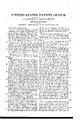
Beit known that I, L. B. BATQI-IELIJER, of Arlington, the county ofiBennington and State of Vermont, have invented a new and Improved Railroad Brake, and 1 do herebydeclare that the following is a full, clear, and exact description of the ,construction and operation ofthe same, reference being had to the annexed drawings, making a part of this specification, in which-.- I I Figure 1, is a. plan or top yiew of the platform of a car with trucks attached showing myimproved brake attached to the; Fi 2, is a longitudinal vertical section of the same, taken at the line 00, aa? Fig. 1. Fig. 3, isan under view of oneof trucks.
the vibrating bars. Fig is an enlarged view of a portion Fig.2, v
Similar letters of reference indicate corresponding parts in each of the several figures. I H
The natureof my invention consists in causing the shoes to act upon the wheels by means of levers attached to vibrating bars which have each a revolving vertical standard upon them surmounted by a hand wheel. A vibrating rod or bar is placed at each end of the platform of the car. The vertical standards are connected by a chain, and as either of the standards abovementioned are turned the chain is moved upon it and the vibrating bars brought nearer together, the bar acting upon the levers above mentioned and causing the shoes to act upon the wheels. as will be hereafter more fully described. The vibrating bars being forced back to their original position by springs. Two levers, one on each vibrating bar, are connected by cross rods or chains, so that with the aid of adjustable levers, which will be fully shown and explained hereafter, the bufler rods will act upon the vibrating bars and consequently the shoes upon the wheels in a greater or less time as desired.
To enable others skilled in the art to make and use by invention, I will proceed to describe its construction and operation.
A, represents the platform of a car and B, B, are trucks of ordinary construction attached to the platform in the usual way. C, C, are vibrating bars attached to the under sides of the cross pieces (a) of the platform. See Fig. 3. These bars C, C, have slots (1)) in them a slot being at each end of the bars 'and a screw (0) passes through each slot into the cross'pieces (a) the heads of the screws retaining the bars 0, (3,, against the cross pieces (a). By this means the bars are allowed to vibrate the length of the slots.
D, D, are springs attached to the inner cross pieces (a). The outer ends of these springs bear upon the inner .ends of the vibrating bars as plainly indicated in Fig. 1.-
ends of which are stepped in the vibrating bars C, ,C. See'Figs. 2 and4. These stand.-
aids are surmounted with hand wheels F.
G, G, are the bearings of the standards H,is a 'rodw hich runs longitudinally underneath the platform A, and is connected at each end by a chain to the standards E, E. See Figs. 1 and 2. r
I, I,are levers the upper ends of which fit, in the vibratingbars C, C, there being a 1 lever to each bar. To the lower end of each lever I, there are attached rods J, K, see' Fig. 2, the rod J, being connected to the outer cross "-bar L, which has a shoe M, at
each" end, and the rod K, connected to the inner cross rod N, which also has shoes M,
i a r s5 E, E, are vertical standards the lower one at each end. These shoes and cross bars are seen in Fig. 2. Now it will be seen that if either the vertical standards E, E, are turned the rod H, will be shortened as the .chain at the end of the rod will be wound around the standard that is turned; and consequently the two vibrating bars C, G,
will be brought nearer together and will force the upper ends of the levers I, I, inward or toward each other, while the rods J, will draw the cross bars L, with their shoes M, against the outer pairs of wheels and the rods K, will draw the inner cross bars N, with their shoes against the inner pairs of wheels, and it will be seen that the action of the shoes against the wheels will be instantaneous, asthere is no slack chain to be wound up before the shoes are brought in contact with the wheels. The springs D, '1), force the vibrating bars C, C, back to their original position as soon as the standard is relieved from the hand of the brakeman.
0, O, are levers having their fulcra' at (h and attached by pivots ((Z) (d) to the upper surface of the vibrating bars C, C To the outer end of each lever 0, there is attached by a chain a rod P, which is connected to the end of the vibratingbarC, of l Fig. 1. It will be seen that by this arrangement if either vibrating bar C, is moved without operating or turning either of the standards E, a corresponding opposite motion is communicated to the other vibrating bars.
R, S, are levers which rest on the upper surfaces of the vibrating bars. B, have their fulcra at (e) and the levers S, are attached by pivots to the vibrating bars.
Each pair of levers R, S, are connected by.
a link T. The buffer rods designated by A, are attached to the levers, R, as shown in all the figures, and more'particularly in Fig. 1. Now it will be seen that when either buffer is acted upon it will throw inward of course its lever B, to Which it is attached, and as the lever R, is connected by the link T, to the lever S, which is attached by a pivot to the vibrating bar, the lever S, and vibrating bar will be forced inward and a corresponding opposite motion communicated to the opposite vibrating bar on the other truck by means of the levers O, O, and cross rods P, as before stated. Thus the shoes are made to act upon the wheels either by turning the vertical standards E, or by the action of the buffers.
The outer ends ofthe lever S, may be secured at any desired point by having a chain pass through their ends and around a shaft U, having a ratchet and pawl upon it as seen on one of the trucks in Fig. 1. The adjustment in this way of the ends of the The levers levers S, S, and the putting of the link T, in
either of the several holes in the levers R, S,
as indicated in Fig. 1, will cause a greater or less amount of leverage upon the vibrating bars C, and the buifers may be made. to
act quickly or slowly upon the brakes as will readily be seen.
The object of the above invention is to obtain a quick action of the brakes when the standards are turned, and to'have nearly all the power expended in turning the standards exerted upon the brakes. In the ordinary brakes in use there is not quick acent, is
Operating the levers I,,I, :Which are attached by the rods J, and K, to the cross bars L, M, by means of vibrating bars C, C,
said bars C, being moved or operated either by turning the standards E, E, or by the action of the buffer rods upon the levers R,'S,
both devices being attached to the trucks,
and otherwise constructed and arranged substantially as herein set forth.
v LUCIEN B. BATCHELLER: Witnesses:
I. HENRY HOBART.
R. L. ANDREW.
Publications (1)
| Publication Number | Publication Date |
|---|---|
| US10440A true US10440A (en) | 1854-01-24 |
Family
ID=2070764
Family Applications (1)
| Application Number | Title | Priority Date | Filing Date |
|---|---|---|---|
| US10440D Expired - Lifetime US10440A (en) | Bailroad-cie |
Country Status (1)
| Country | Link |
|---|---|
| US (1) | US10440A (en) |
Cited By (3)
| Publication number | Priority date | Publication date | Assignee | Title |
|---|---|---|---|---|
| US20040064864P1 (en) * | 2002-10-01 | 2004-04-01 | Dirr Michael A. | Hydrangea macroophylla named 'Lady in Red' |
| US20110022814A1 (en) * | 2004-11-05 | 2011-01-27 | Commvault Systems, Inc. | Methods and system of pooling storage devices |
| CN109479715B (en) * | 2018-12-17 | 2021-08-31 | 江苏省农业科学院 | Method for rapidly breeding hydrangea macrophylla endless summer by using tissue culture seedling leaves |
-
0
- US US10440D patent/US10440A/en not_active Expired - Lifetime
Cited By (3)
| Publication number | Priority date | Publication date | Assignee | Title |
|---|---|---|---|---|
| US20040064864P1 (en) * | 2002-10-01 | 2004-04-01 | Dirr Michael A. | Hydrangea macroophylla named 'Lady in Red' |
| US20110022814A1 (en) * | 2004-11-05 | 2011-01-27 | Commvault Systems, Inc. | Methods and system of pooling storage devices |
| CN109479715B (en) * | 2018-12-17 | 2021-08-31 | 江苏省农业科学院 | Method for rapidly breeding hydrangea macrophylla endless summer by using tissue culture seedling leaves |
Similar Documents
| Publication | Publication Date | Title |
|---|---|---|
| US10440A (en) | Bailroad-cie | |
| US14385A (en) | barnes | |
| US21086A (en) | Brake foe | |
| US13503A (en) | Wagon | |
| US14640A (en) | evans | |
| US16011A (en) | Bailboad-car bbake | |
| US83508A (en) | Improved car-brake | |
| US19917A (en) | Bailboad-cab brake | |
| US581270A (en) | Rail-brake | |
| US23259A (en) | Car-brake | |
| US60850A (en) | Improved cae-beaee | |
| US948246A (en) | Wagon-brake. | |
| US123133A (en) | Improvement in car-brakes | |
| US1187857A (en) | Brake-lever for railway hand-cars. | |
| US27486A (en) | Island | |
| US11517A (en) | Raikboad-cab | |
| US193401A (en) | Improvement in hand-trucks | |
| US13108A (en) | Brake for vehicles | |
| US19260A (en) | Railroad-car | |
| US11130A (en) | Radial arm eor car-brakes | |
| US621653A (en) | Brake-adjusting mechanism | |
| US14154A (en) | Machine fob | |
| US17257A (en) | Bumper railroad-car brake | |
| US5537A (en) | Tail-block of sawmills | |
| US47408A (en) | Improvement in carriage-jacks |