US1246292A - Teat-cup for milking-machines. - Google Patents
Teat-cup for milking-machines. Download PDFInfo
- Publication number
- US1246292A US1246292A US14973917A US14973817A US1246292A US 1246292 A US1246292 A US 1246292A US 14973917 A US14973917 A US 14973917A US 14973817 A US14973817 A US 14973817A US 1246292 A US1246292 A US 1246292A
- Authority
- US
- United States
- Prior art keywords
- lining
- casing
- vacuum
- duct
- teat
- Prior art date
- Legal status (The legal status is an assumption and is not a legal conclusion. Google has not performed a legal analysis and makes no representation as to the accuracy of the status listed.)
- Expired - Lifetime
Links
Images
Classifications
-
- A—HUMAN NECESSITIES
- A01—AGRICULTURE; FORESTRY; ANIMAL HUSBANDRY; HUNTING; TRAPPING; FISHING
- A01J—MANUFACTURE OF DAIRY PRODUCTS
- A01J5/00—Milking machines or devices
- A01J5/04—Milking machines or devices with pneumatic manipulation of teats
- A01J5/08—Teat-cups with two chambers
Definitions
- the teats of different animals vary greatly in diameter, and one of the principal objects of my invention is to produce a universal teat cup which may be used with equal effect upon teats of large and small diameter. Briefly, this is accomplished byl employing a small expansible lining and providing means by which the degree of vacuum on the outside of the lining may, in a practical manner, be regulated with respect to the constant vacuum inside of the lining,l thereby regulating the degree to which the lining will be expanded. Another object of the invention is.
- Another object is to provide simple, efficient and durable means for removably supporting the lining. y.
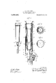
- Figure 1 is a side elevation of my improved teat cup, the pipeconnections being broken away. s
- Fig. 2 is a central longitudinal sectio with parts shown in full lines, the same being shown' as engaged with a teat, the lin- Specibation of Letters Patent.
- Patentes not. is, rara.
- Fig. 4 1s a cross section on line 4-4 of Fig. 2, the lining or ination being shown in collapsed condition by dotted lines.
- the casing 1 is formed of metal or other relatively rigid material and is preferably formed of tubing. It has an inturned flange 9. at its bottom and' a bead 3 at its top forming an internal annular groove 4.
- the ,lining or inflation 5 is formed of resilient material, preferably rubber, and is provided with a circumferential rib orlbead 6 near its upper end adapted to seat in the groove 4. It possesses suiiicient stiffness to securely hold the bead in the groovev 4 and thus support the lining.
- the lining may be readily removed, however, by simply collapsing it at the upper end and disengaging the bead from the groove.
- the lining extends above the bead 6 and at the upper end has an inwardly extending annular flan e 7, which embraces the teat at the root as s own in Fig. 2.
- a lining of comparatively small diameter is used,-one that will fit a Asmall teat when the lining is in normal, unstretched condition.
- ⁇ it is expanded by producing a greater vacuum outside the lining than inside, in the manner presently to be described.
- the lining has an opening 8 in the c bottom to receive the nipple 9.
- This nipple isconnected to a tube l0 which exerts a constant vacuum and conveys the milk to the milk receptacle.
- the bottom 12 of the casing has a groove 13 which receives the annular flange 2 and holds the bottom in position.
- this bottom disk By forming this bottom disk wholly or in part of .rubber or similar material, it may be conveniently and readily placed or removed and requires no fastening device other than the flange and groove. Positive fastening devices may, however, be employed.
- Said Abottom disk has an opening 1e through which the nipple 9 passes. ln the form shown the nipple is vertically slidable in the bottom, being frictionally held in any position to which it may be adjusted. As a result, it is a simple matter, when the lining lengthens, to lower the nipple and taire up the slack.
- the bottom disk also has an opening 16 for receiving the nipple 17 which communicates with the space between the lining and the casing.
- rllube 18 communicates with the nipple 17 and with a pulsator which produces a pulsating vacuum within the casing.
- Some pulsators after the maximum vacuum has been reached, admit air at atmospheric pressure while others introduce air under positive pressure higher than atmospheric pressure.
- means will be employed capable of producing a higher vacuum in the space outside of the lining than it produces in the space within the lining.
- valve seat faces inward so that the valve is free to rise when air is rushing toward the space between the lining and the casing. ⁇ When the air is being exhausted therefrom, however, it will assist gravity in urging the valve toward its seat. The valve will then restrict the passage and consequently the intensity of the vacuum produced inside or" the casing at each pulsation may be regulated by raising or lowering the stop 25.
- the operator will screw the stop 25 upward a considerable distance so as to afford a full :free opening for the air to tlow :trom thegallegas But it is desirable that the pressure upon a small teat, when the lining is deflated, shall be approximately as great as the pressure upon a large teat, and this is rendered possible in my device by the presence of valve 22 which freely opens and lets the atmospheric air rush in as fast in the case of a small teat as in the case of a large one. lt will thus be seen that by regulating the position of the stop 25, the extent to which the lining will expand may be regulated and hence the lining may be made to accommodate itself to teats of various sizes.
- a teat cup having a casing, an expansible lining therein, a duct leading from inside the lining to a point outside the casing, a duct leading from outside the lining to a point outside the casing, and means in the latter duct for retarding the outflow and permitting free inflow of air.
- a teat cup having a tubular casing, a resilient lining-therein, a duct leading' from theinside of the lining for producing a partial vacuum therein, a duct leading from the inside of the casing, external to the lining for producing a greater vacuum therein, and
- a teat cup havinga casing, a diametrically expansible lining therein, a vacuum duct leading from inside the lining to a point outside the casing for creating a partial vacuum within the lining, a high vacuum duct leading to the outside of the casing from a point between the casing and the lining for creating a greater vacuum between the lining and the casing, and thereby causing the lining to expand, and a reducing valve in the last mentioned duct tor regulating the degree of vacuum created within the 4 casing outside of the lining to thereby control the size to which the lining shall expand.
- teat cup having a casing, a resilient lining supported from the upper end thereof, the lower end terminating above the and the lining,
- a teat cup having a casing, a depending resilient lining within said casing terminating short of the bottom thereof, a suction tube leading outward from the space between the lining and the casing, a second suction tubo leading out through the bottom of the casing ⁇ from the inside of the lining, and means whereby the length of the last mentioned suction tube between the bottom of the lining and the bottom of the casing may be shortenedlto compensate for the increased length of the lining due to deterioration.
- a teat cup having a casing, a resilient lining suspended at its upper end from the casing and extending down to a point above the bottom of the casing, a vacuum duct leading from the space between the casing and atube leading from the inside of the lining out through the bottom of the casing, said tube being vertically adjustable with casing to thereby compensate for the permanent stretching and elongation of the lining.
- a teat cup having a tubular easing, a ficxible lining supported therein, a removable bottom or said casing, and two ducts supported by said bottoni, one of said ducts leading from the inside of the lining and the other leading from the space between the lining and the casing.
- a teat cup having a tubular casing, a fiexible lining suspended therein from the top thereof, a removable bottom for said casing, and two ducts leading through the bottom, one communicating with the inside of y the lining and the other communicating with the space between the lining and the casing, the bottom being disk-like and somewhat exible, and the casing and bottom having interfitting, annular portions, Whereby the bottom is removably held to the casing.
- a teat cup having a tubular casing, an expansible lining therein, a milk duct leading out from the inside of the lining, said milk duct having a vacuum therein, a vacuum duct leading to the space between the lining and the casing, said vacuum duct having a pulsating vacuum therein, the
- a teat cup having a tubular casing, an expansible lining therein, a' milk duct leading out from the inside of the lining, said milk duct having a vacuum therein, a vacuum duct leading to the space between the lining and the casing, said vacuum duct having a pulsating vacuum therein, the maximum tension whereof is greater than the tension of the vacuum in the milk duct, a check valve in the vacuum duct opening freely inward, and an adjustable stop for limiting the extent to which the check valve may close the passage through the duct.
- a teat cup having a tubular casing
- an expansible lining therein of small diameter for accommodating teats of small diameter a milk duct leading out from the inside of the lining, said milk duct being under constant vacuum, a vacuum duct communicating with the space between the lining and the casing, said vacuum duct having a pulsating vacuum, the maximum intensity whereof is greater, than the vacuum in the milk duct, a valve casing in said vacuum -duct, said casing having a valve seat facing inward toward thespace between the lining and the casing, a valvein said casing cooperating with said seat, and means for limiting the movement of said valve.
- a teat cup having a tubular casing, an expansible lining therein of small diameter for accommodating teats of small diameter, a milk duct leading out from the inside of the lining, said milk duct being under constant vacuum, a vacuum duct communieating with the space between the lining and the easing, said vacuum duct having a pulsating vacuum, the maximum intensity whereof is greater than the vacuum in the milk duct, a valve casing in said vacuum duct, said casing having avalve seat facing inward toward the space between the lining Aand the casing, a valve in said casing co- ARTHUR c. GARTNEY. [1.. sa I -Witnessesz HOWARD M. Cox, M. S. RosENzwEIe.
Description
A. C. IVIACARTNEY.
TEM CUP FOR MILKING MACHINES.
'APPLxcATloN FILED FEB.20.1917.
Patented Nov. 13, 1917.
maar o ARTHUR C. MACARTNEY, OF CHICAGO, ILLINOIS, ASSIGNOR T PINE TREE MILKING MACHINE COMPANY, OF CHICAGO, ILLINOIS, A CORPORATION 0F ILLINOIS.'
TEA'r-CUP ron MILKING-Maenmns.
is caused to pulsate or contract and expand.I
The teats of different animals vary greatly in diameter, and one of the principal objects of my invention is to produce a universal teat cup which may be used with equal effect upon teats of large and small diameter. Briefly, this is accomplished byl employing a small expansible lining and providing means by which the degree of vacuum on the outside of the lining may, in a practical manner, be regulated with respect to the constant vacuum inside of the lining,l thereby regulating the degree to which the lining will be expanded. Another object of the invention is. to provide a convenient construction by which allowance can be made for the elongation of the lining as a result of wear and deterioration of the rubber or similar material kof which it is composed.l It is known to those familiar with teat cups that when a rubber lining is employed, it gradually lengthens. This is due to the natural loss of resllience due to constant expansion and contraction and to the action of the fat to which. it is necessarily exposed. .As a result of my invention this elongation' is taken care of simply and eifectually.
Another object is to provide simple, efficient and durable means for removably supporting the lining. y.
Other objects, including those relating to structural details will become apparent from the following description and claims.
I obtain my objects by the mechanism illustrated in the accompanying drawings, in which: n
Figure 1 is a side elevation of my improved teat cup, the pipeconnections being broken away. s
Fig. 2 is a central longitudinal sectio with parts shown in full lines, the same being shown' as engaged with a teat, the lin- Specibation of Letters Patent.
Application filed February 20, 1917.
Patentes not. (is, rara.
Serial No. 149,73.
Fig. 4 1s a cross section on line 4-4 of Fig. 2, the lining or ination being shown in collapsed condition by dotted lines.
In the drawing similar reference characters refer to similar parts throughout the several views, and the sectional views are taken looking in the direction of the arrows at the ends of the section lines.
Referring to the drawings, the casing 1 is formed of metal or other relatively rigid material and is preferably formed of tubing. It has an inturned flange 9. at its bottom and' a bead 3 at its top forming an internal annular groove 4. The ,lining or inflation 5 is formed of resilient material, preferably rubber, and is provided with a circumferential rib orlbead 6 near its upper end adapted to seat in the groove 4. It possesses suiiicient stiffness to securely hold the bead in the groovev 4 and thus support the lining. The lining may be readily removed, however, by simply collapsing it at the upper end and disengaging the bead from the groove. The lining extends above the bead 6 and at the upper end has an inwardly extending annular flan e 7, which embraces the teat at the root as s own in Fig. 2.
When my invention is availed of to its full extent, a lining of comparatively small diameter is used,-one that will fit a Asmall teat when the lining is in normal, unstretched condition. 'When it is to `be used on large teats, `it is expanded by producing a greater vacuum outside the lining than inside, in the manner presently to be described. The lining has an opening 8 in the c bottom to receive the nipple 9. This nipple isconnected to a tube l0 which exerts a constant vacuum and conveys the milk to the milk receptacle. The bottom 12 of the casing has a groove 13 which receives the annular flange 2 and holds the bottom in position. By forming this bottom disk wholly or in part of .rubber or similar material, it may be conveniently and readily placed or removed and requires no fastening device other than the flange and groove. Positive fastening devices may, however, be employed. Said Abottom disk has an opening 1e through which the nipple 9 passes. ln the form shown the nipple is vertically slidable in the bottom, being frictionally held in any position to which it may be adjusted. As a result, it is a simple matter, when the lining lengthens, to lower the nipple and taire up the slack.
The bottom disk also has an opening 16 for receiving the nipple 17 which communicates with the space between the lining and the casing. rllube 18 communicates with the nipple 17 and with a pulsator which produces a pulsating vacuum within the casing. Some pulsators, after the maximum vacuum has been reached, admit air at atmospheric pressure while others introduce air under positive pressure higher than atmospheric pressure. When used under the conditions contemplated by one aspect of my invention, means will be employed capable of producing a higher vacuum in the space outside of the lining than it produces in the space within the lining. For reasons presently to be explained, it is desirable, in order to obtain the full beneiits of my invention, to provide means whereby the intensity of the vacuum outside the lining may be readily controlled, and it is also desirable to provide means whereby air, either atmospheric or under pressure, will have a more ready ingress than egress to this space. ln the embodiment shown, l forni a valve casing 2O in the duct 17, 18, said casing having a seat 21 for the check or reducing valve 22. rlhis valve is guided vertically by a stem 28 which slides in the cylindrical dome 24 of the casing. An adjustable stop25 provided preferably with a knurled head 26 screws up through the.
bottom of the casing and limits the extent to which the valve may approach its seat. rllhe valve seat faces inward so that the valve is free to rise when air is rushing toward the space between the lining and the casing. `When the air is being exhausted therefrom, however, it will assist gravity in urging the valve toward its seat. The valve will then restrict the passage and consequently the intensity of the vacuum produced inside or" the casing at each pulsation may be regulated by raising or lowering the stop 25.
ln operation, let it be assumed that a small rubber lining is in place within the casing and that the pulsator first exhausts air 'from the space between the lining and casing and then admits air under atmosphericpressure. Let it be assumed also that the maximum vacuum in the tube 18 will be greater than the constant vacuum in the tube 10. if, now, it is desired to apply the teat cup to a teat ot large diameter, the operator will screw the stop 25 upward a considerable distance so as to afford a full :free opening for the air to tlow :trom thegallegas But it is desirable that the pressure upon a small teat, when the lining is deflated, shall be approximately as great as the pressure upon a large teat, and this is rendered possible in my device by the presence of valve 22 which freely opens and lets the atmospheric air rush in as fast in the case of a small teat as in the case of a large one. lt will thus be seen that by regulating the position of the stop 25, the extent to which the lining will expand may be regulated and hence the lining may be made to accommodate itself to teats of various sizes.
lt will be understood that the design of the parts may be somewhat varied without de arting from the spirit of the invention.
' aving thus described my invention, what l claim as new and desire to secure by Letters Patent, is:
1. A teat cup having a casing, an expansible lining therein, a duct leading from inside the lining to a point outside the casing, a duct leading from outside the lining to a point outside the casing, and means in the latter duct for retarding the outflow and permitting free inflow of air.
2. A teat cup having a tubular casing, a resilient lining-therein, a duct leading' from theinside of the lining for producing a partial vacuum therein, a duct leading from the inside of the casing, external to the lining for producing a greater vacuum therein, and
means in the latter duct for regulating the amount to which the external vacuum shall exceed the internal to thereby regulate the size to which the lining shall expand.
3. A teat cup havinga casing, a diametrically expansible lining therein, a vacuum duct leading from inside the lining to a point outside the casing for creating a partial vacuum within the lining, a high vacuum duct leading to the outside of the casing from a point between the casing and the lining for creating a greater vacuum between the lining and the casing, and thereby causing the lining to expand, and a reducing valve in the last mentioned duct tor regulating the degree of vacuum created within the 4 casing outside of the lining to thereby control the size to which the lining shall expand. i y
4C. teat cup'having a casing, a resilient lining supported from the upper end thereof, the lower end terminating above the and the lining,
lower end of the casing, means for creating a partial vacuum' in the space between the casing and the lining, and a duct extending from the lower end of the lining out through the bottom of the casing, the e Iective length' of the duct within the casing being variable.
5. A teat cup having a casing, a depending resilient lining within said casing terminating short of the bottom thereof, a suction tube leading outward from the space between the lining and the casing, a second suction tubo leading out through the bottom of the casing `from the inside of the lining, and means whereby the length of the last mentioned suction tube between the bottom of the lining and the bottom of the casing may be shortenedlto compensate for the increased length of the lining due to deterioration.
G. A teat cup having a casing, a resilient lining suspended at its upper end from the casing and extending down to a point above the bottom of the casing, a vacuum duct leading from the space between the casing and atube leading from the inside of the lining out through the bottom of the casing, said tube being vertically adjustable with casing to thereby compensate for the permanent stretching and elongation of the lining.
7. A teat cup having a tubular easing, a ficxible lining supported therein, a removable bottom or said casing, and two ducts supported by said bottoni, one of said ducts leading from the inside of the lining and the other leading from the space between the lining and the casing.
8. A teat cup having a tubular casing, a fiexible lining suspended therein from the top thereof, a removable bottom for said casing, and two ducts leading through the bottom, one communicating with the inside of y the lining and the other communicating with the space between the lining and the casing, the bottom being disk-like and somewhat exible, and the casing and bottom having interfitting, annular portions, Whereby the bottom is removably held to the casing.
9. A teat cup having a tubular casing, an expansible lining therein, a milk duct leading out from the inside of the lining, said milk duct having a vacuum therein, a vacuum duct leading to the space between the lining and the casing, said vacuum duct having a pulsating vacuum therein, the
maximum tension whereofis greater than the tension of the vacuum in the milk duct, and aA check valve in the vacuum duct, said reference to the bottom of the check valve opening freely inward to admit air to the space between the lining and the casing and retard the flow in the opposite direction.
10. A teat cup having a tubular casing, an expansible lining therein, a' milk duct leading out from the inside of the lining, said milk duct having a vacuum therein, a vacuum duct leading to the space between the lining and the casing, said vacuum duct having a pulsating vacuum therein, the maximum tension whereof is greater than the tension of the vacuum in the milk duct, a check valve in the vacuum duct opening freely inward, and an adjustable stop for limiting the extent to which the check valve may close the passage through the duct.
l1. A teat cup having a tubular casing,
- an expansible lining therein of small diameter for accommodating teats of small diameter, a milk duct leading out from the inside of the lining, said milk duct being under constant vacuum, a vacuum duct communicating with the space between the lining and the casing, said vacuum duct having a pulsating vacuum, the maximum intensity whereof is greater, than the vacuum in the milk duct, a valve casing in said vacuum -duct, said casing having a valve seat facing inward toward thespace between the lining and the casing, a valvein said casing cooperating with said seat, and means for limiting the movement of said valve.
l2. A teat cup having a tubular casing, an expansible lining therein of small diameter for accommodating teats of small diameter, a milk duct leading out from the inside of the lining, said milk duct being under constant vacuum, a vacuum duct communieating with the space between the lining and the easing, said vacuum duct having a pulsating vacuum, the maximum intensity whereof is greater than the vacuum in the milk duct, a valve casing in said vacuum duct, said casing having avalve seat facing inward toward the space between the lining Aand the casing, a valve in said casing co- ARTHUR c. GARTNEY. [1.. sa I -Witnessesz HOWARD M. Cox, M. S. RosENzwEIe.
Priority Applications (1)
| Application Number | Priority Date | Filing Date | Title |
|---|---|---|---|
| US14973917A US1246292A (en) | 1917-02-20 | 1917-02-20 | Teat-cup for milking-machines. |
Applications Claiming Priority (1)
| Application Number | Priority Date | Filing Date | Title |
|---|---|---|---|
| US14973917A US1246292A (en) | 1917-02-20 | 1917-02-20 | Teat-cup for milking-machines. |
Publications (1)
| Publication Number | Publication Date |
|---|---|
| US1246292A true US1246292A (en) | 1917-11-13 |
Family
ID=3314063
Family Applications (1)
| Application Number | Title | Priority Date | Filing Date |
|---|---|---|---|
| US14973917A Expired - Lifetime US1246292A (en) | 1917-02-20 | 1917-02-20 | Teat-cup for milking-machines. |
Country Status (1)
| Country | Link |
|---|---|
| US (1) | US1246292A (en) |
Cited By (4)
| Publication number | Priority date | Publication date | Assignee | Title |
|---|---|---|---|---|
| US2473379A (en) * | 1943-12-09 | 1949-06-14 | Separator Ab | Teat cup |
| DE1172078B (en) * | 1961-08-24 | 1964-06-11 | Daniel Olie Noorlander | Teat rubber |
| US5482004A (en) * | 1994-05-16 | 1996-01-09 | Alfa Laval Agri, Inc. | Collapsible teat liner with reinforced barrel |
| US5493995A (en) * | 1994-05-16 | 1996-02-27 | Alfa Laval Agri, Inc. | Collapsing teat cup liner with tapering barrel wall |
-
1917
- 1917-02-20 US US14973917A patent/US1246292A/en not_active Expired - Lifetime
Cited By (4)
| Publication number | Priority date | Publication date | Assignee | Title |
|---|---|---|---|---|
| US2473379A (en) * | 1943-12-09 | 1949-06-14 | Separator Ab | Teat cup |
| DE1172078B (en) * | 1961-08-24 | 1964-06-11 | Daniel Olie Noorlander | Teat rubber |
| US5482004A (en) * | 1994-05-16 | 1996-01-09 | Alfa Laval Agri, Inc. | Collapsible teat liner with reinforced barrel |
| US5493995A (en) * | 1994-05-16 | 1996-02-27 | Alfa Laval Agri, Inc. | Collapsing teat cup liner with tapering barrel wall |
Similar Documents
| Publication | Publication Date | Title |
|---|---|---|
| KR102583637B1 (en) | breast shield | |
| US3096740A (en) | Teat cup liner construction | |
| US2997980A (en) | Teat cup inflation | |
| US3308788A (en) | Teat cup assembly | |
| US3255732A (en) | Method and apparatus for teat cup inflation control in machine milking | |
| US1859213A (en) | Apparatus for milking | |
| US1246292A (en) | Teat-cup for milking-machines. | |
| US3172391A (en) | High speed milking system | |
| US2702526A (en) | Valve device for milker claws | |
| US1859214A (en) | Milking machine | |
| US2462583A (en) | Teat cup | |
| US1396987A (en) | Milking-machine | |
| US2120556A (en) | Inflation for milking machine cups | |
| US3176654A (en) | Milking device | |
| US2570684A (en) | Minnow bucket | |
| US948608A (en) | Milking-machine teat-cup. | |
| US2282159A (en) | Teat cup | |
| US2470169A (en) | Mechanical milking apparatus | |
| US1513189A (en) | Teat cup for milking machines | |
| US1476788A (en) | Teat cup for milking machines | |
| US1105681A (en) | Suction-cup for milking-machines. | |
| US940454A (en) | Breast-pump. | |
| US1397840A (en) | Teat-cup | |
| US807372A (en) | Pneumatic teat-cup. | |
| US2425901A (en) | Milker nipple |