US1466963A - Amusement device - Google Patents
Amusement device Download PDFInfo
- Publication number
- US1466963A US1466963A US464840A US46484021A US1466963A US 1466963 A US1466963 A US 1466963A US 464840 A US464840 A US 464840A US 46484021 A US46484021 A US 46484021A US 1466963 A US1466963 A US 1466963A
- Authority
- US
- United States
- Prior art keywords
- platform
- cars
- rotary
- raised portions
- rotatable
- Prior art date
- Legal status (The legal status is an assumption and is not a legal conclusion. Google has not performed a legal analysis and makes no representation as to the accuracy of the status listed.)
- Expired - Lifetime
Links
Images

Classifications
-
- A—HUMAN NECESSITIES
- A63—SPORTS; GAMES; AMUSEMENTS
- A63G—MERRY-GO-ROUNDS; SWINGS; ROCKING-HORSES; CHUTES; SWITCHBACKS; SIMILAR DEVICES FOR PUBLIC AMUSEMENT
- A63G1/00—Roundabouts
- A63G1/48—Roundabouts with turntables and movably-mounted vehicles thereon which move to the outside when the roundabout is rotated
-
- A—HUMAN NECESSITIES
- A63—SPORTS; GAMES; AMUSEMENTS
- A63G—MERRY-GO-ROUNDS; SWINGS; ROCKING-HORSES; CHUTES; SWITCHBACKS; SIMILAR DEVICES FOR PUBLIC AMUSEMENT
- A63G1/00—Roundabouts
- A63G1/34—Roundabouts with seats moving in an undulating track
Landscapes
- Toys (AREA)
Description
Sept. 4, 1923. 1,466,963
H. N. RIDGWAY AMUS EMENT DEVICE Filed April 27, 1921 1 2 Sheets-Sheet 1 Fig.1.
lnvenTor.
Sept. 4, 1923. 1,466,963
H. N'. RIDGWAY AMUSEMENT DEVI GE Filed April 27, 1921 2 Sheets-Sheet2 \nvenTor.
HerberT NRidgwuy WM wxjivmm Affys.
Patented Sept. 4, i923.
aeaaee HERBERT n. RIDGWAY, or wnvzrrraor, MASSACHUSETTS.
AMUSEMENT DEVICE.
Application filedAplil 27, 1921. 7 Serial No. 464,840. i
To aZZ whom it may concern: Be it known that I. Hrnnmzr N. RIDGWAY, a citizen of the United States.
and a resident of inthrop, county of Suffolk State of illassach'usetts have invented an 1111-,
provement in Amusement Devices, of which the following description, in COHHQCt-lOllWlth the accompanying drawing. is a specification. like characters on the drawing representing like parts. i 7
This invention relates to" amusement devices of that type comprising a rotatable platform and one or 'inore'passenger cars operating on said platform and constructed to travel freely in any direction, said cars receiving their movementby or through the rotary movement of the platform. 7 In some amusement'devicesof this type the rotatable platform is surrounded by a stationary platform or spillway which is arranged so that as the rotatable platform ro tates the cars are thrown ofl onto the spillwayby centrifugal force. ment devices of thistype the spillway is arranged at an inclination so that the cars will gravitate back onto the rotary'platform after the centrifugal force by which'they are thrown outwardly has expended itself, 1
One feature of the presentinvention re lates to a rotary. platform havinga novel construction by which the cars travelling thereover will be given a rocking movement during their travel thus adding to the pleasure and excitement, which the' passengers experience in the travel of the car. This rocking motion may be imparted to the cars in various ways but preferably by male ing the surface of the platform .with raised portions and depressed portions thusgiving a more or less sinuous contour to the platform. The travel of the carover the raised portions and depressed portions will cause the car to have a rocking motion which simulates the rocking motion of a body on the water. 7
When my invention is applied to an amusement apparatus in which the rotatable platform'is surrounded bya spillway, one feature of the invention'relates to an arrangement of raised portions by which the time necessary to develop the required centrifugal force to throw the cars off ontothe spillway may be considerably reducedand thisis accomplishedby arranging the raised portions so that they help to overcome the inertia of the cars as the rotatable platform.
ter thereof. and
appended claims 7 rotatable platform.
In some amuse? this latter type is starts to rotate so that the cars will turn with the rotatable plaform until sufficient centrifugal force 15 developed to throw them onto the :spillway;
Another feature of my inventionrelates to a rotatablejplatform constructed so that the cars naturally gravitate toward the cena resilient bumper which causes the cars to rebound when they strike it.
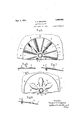
In order to invention I have illustrated in the drawings some selected embodiments thereof. which will now be descrlbed after which pointed out in the the novel features will be Fig. 1 is. a cross sectional Fig. 2 is an enlarged Fig. 3 is a section on the line 3-8, Fig. Fig. 4% is a section on the line 4- 1, Fig. 2.
Fig. 5 is a plan view of a rotatable provided at the center with view of an amusement apparatus embodying my invention.
plat
give an understanding of my- I planview 0f the 1 form showing a different embodiment of 7 my invention. 7
Fig.6 is a section on the line-6+6, Fig. 5. Fig. 7 is a section on the line "('7, Fig. 5. Fig. 8is a plan view of a rotatable plat form showing stilla different embodiment of the invention.
F ig. 9 is' -a section on'the line 99,Fig. 8.
My invention may be embodied in an amusement device in which the cars are confined to the rotatable platform or in an amusement device in which provided outside of the rotatable platform so' that the; cars which are thrown from the platform by centrifugal force may pass on to the vspillway.
United States No. 1,279,911 dated September 24, 1918 and in Figs. 1 and 2 I have shown my present invention as applied to this type of amusement apparatus. In said figures, 1 indicates a rotatable platform which is" constructed to rotate about its center'and is supported on a circular track 2,
said platform being rotated by any suitsuch for instance 'as a m0tor3. geared to the platform by means of a spillvvay is An amusement device of V illustrated in my patent,
6 indicate passenger-carrying cars each adapted to contain a plurality of passengers and each constructed to travel freely in any direction. Each car is preferably circular in shape and is surrounded by a buffer 7 as usual in amusement devices of this kind. I
- The parts thus far described are, or'ma-y be. all as shown in my prior Patent No. 1,279,911 and in the operation of the device the cars (5 will naturally gravitateftoward the centerof the rotatable platform and as the latter is rotated they will be thrown by centrifugal force outwardly onto the stationary platform 8 which forms a spillway. As soon as the centrifugal force with which the cars were projected off from the rotary platform has expended itself the cars will gravitate back toward the rotatable platform.
In accordance with my present invention I construct the rotatable platform 1 so that it will give thev cars a rocking motion as well as the outward motion due to centrifugal force and this 1s preferably accomplished by providing the surface of the platform 1 with raised. portions having sloping sides over which the cars may travel, said raised portionsforming between them val leys. The movement of any car from one valley over a raised portion and down into the next valley will give the car a rocking motion while it is travelling over thesurface of the platform.
In Fig. 2 these raised portions of the platform are indicated at 9 and the valleys between the raised portions are indicated at 10'. In the construction shown the valleys are at the same level as the main body of the platform and the raised portions 9 are raised from said platform.
These raised portions may extend in various directions without departing from the invention and as illustrating one possible arrangement I have shown them as having a general radial direction. In Fig. 2 the raised portions extend radially but terminate a distance from the periphery 'of the disk 1 and the outer ends of the'raised portionsare preferably rounded or pointed somewhat as shown.
When the rotatable platform 1 is at rest the cars will naturally gravitate toward the center thereofiand will also gravitate into thevalleys 10. hen the platform 1 is r0- .tated the cars'will be subjected to centrifugal force which will increase as the speed of rotation increases until the cars are with the p atform but at the same time any car which. is in one of the valleys will be acted on by one of the raised portions which will tend to move the car around with the platform until the centrifugal force is suflicient to throw the car over onto the spillway. As the cars gravitate back ontothe rotary platform from the spillway they will pass over some of the raised portions 9 and thus will be given a rocking motion. Moreover where thereare a pluing motion which is exhilarating and in creases. the pleasure which the passengers derive from their rides. in the cars.
I regard this radial arrangement of the raised portions 9 as very desirable in the construction shown in Figs. 7 wherein a spillway 8 is employed outside of the'rotary platform 1 because in this construction the said raised portions 9 tend to overcome the inertia of the cars 'when the rotary platform begins to rotate thus causing the cars to rotate with the platform especially instead of allowing the platform to turn around under the cars. Where the cars are thus compelled to rotate with the platform 1 and 2 l the time required in which to develop sufficient centrifugal force to throw the cars outwardly onto the 'spillway is very greatly reduced over that which is required where the rotary platform has a smooth surface,
such as shown in my above-mentioned Patent Woreoverthe rotary arrangement of the valleys 10 is an advantage in'that it tends to guide the cars in a radial directon as they are thrown off from the rotating platform. In Figs. 5 to 9 I have shown constructions embodying my invention in which the cars are confined to'the rotary platform and this is accomplished by placing a wall 11 just outside'of the rotary platform as shown in Figs. 5 and 7 or by placing such a wall on the periphery of the rotary platform I as shown in Figs. 8 and 9. In either case the cars will be confined to the rotary platform.
The extent and direction of the raised and 7 they are shown as extending from r the center clear to the periphery of the platform. While. the radial arrangement of these raised portionsis that which I prefer yet I do not wish to be limited to such an arrangement any arrangement of raised portions which as my invention contemplates i will provide a rocking motion to the cars as they travel in their inderterminate path over the rotary platform. 4
Another feature of my invention relates to the provision of a buffer located centrally of the rotatable platform and which acts to cause any cars gravitating toward the center of the platform to rebound more or less. This buffer is shown as a post '12 rigidly secured to the platform 1 at the central portion and surrounded by a resilient buffer. This buffer comprises a resilient ring 14 surrounding the post 12 and spaced therefrom by suitable springs 15. This ring is sustained in position by means of suspenders 16 attached to the top of the post.
I claim: 7
1. In an amusement device, the combination with a rotary platform turnable about a vertical axis, of a plurality of passengerca-rrying cars thereon and each adapted to travel freely in any direction, said platform having an unobstructed surface in a radial direction whereby the cars are free to travel radially by centrifugal action as the plat form rotates, said platform also having means to assist in overcoming the inertia of the cars as the platform starts in rotation thereby to quickly develop suificient centrifugal force to throw the cars to the outer periphery of the platform.
In an amusement device, the combination with, a rotary platform, of a plurality suflicient size to receive .of passenger-carrying cars thereon and each adapted to travel freely in any direc tion, said platform having radially-arranged raised portions with valleys between them of V the cars.
3. In an amusement device, the combina- 1 tion with a rotary platfornnofa stationary spillway encircling the platform, and a plurality of passenger-carrying carsneaeh adapted to travel freely in any direction, said rotary platform having radially-arranged raised portions with valleys between them of sufiicient size to receive the cars whereby said the cars'in the ugal force is onto the spillway.
n anamusement device, the combinavalleys until sufficient centriftion with a rotary platform, of a plurality raised portions will retain developed to'throw the cars of passenger-carrying cars thereon and each adapted to travel freely in any direction, said platform having raised portions thereon over which the cars may travel thereby to give the cars a rocking motion. 7
5. In an amusement apparatus, the combination with a rotatable platform, of; a
plurality of cars thereon each adapted to travel freely in any direction and means to to have a rocking motion as. they pass over the platform. 7
cause said cars Intestimony whereof, I have signed my name to this specification.
HERBERT N. RIDGWAY.
Priority Applications (1)
| Application Number | Priority Date | Filing Date | Title |
|---|---|---|---|
| US464840A US1466963A (en) | 1921-04-27 | 1921-04-27 | Amusement device |
Applications Claiming Priority (1)
| Application Number | Priority Date | Filing Date | Title |
|---|---|---|---|
| US464840A US1466963A (en) | 1921-04-27 | 1921-04-27 | Amusement device |
Publications (1)
| Publication Number | Publication Date |
|---|---|
| US1466963A true US1466963A (en) | 1923-09-04 |
Family
ID=23845456
Family Applications (1)
| Application Number | Title | Priority Date | Filing Date |
|---|---|---|---|
| US464840A Expired - Lifetime US1466963A (en) | 1921-04-27 | 1921-04-27 | Amusement device |
Country Status (1)
| Country | Link |
|---|---|
| US (1) | US1466963A (en) |
Cited By (2)
| Publication number | Priority date | Publication date | Assignee | Title |
|---|---|---|---|---|
| US4836521A (en) * | 1988-09-23 | 1989-06-06 | Barber Gerald L | Whirlpool amusement ride |
| RU169768U1 (en) * | 2016-04-08 | 2017-03-31 | Андрей Леонидович Смирнов | ATTRACTION "CAROUSEL WATER" |
-
1921
- 1921-04-27 US US464840A patent/US1466963A/en not_active Expired - Lifetime
Cited By (2)
| Publication number | Priority date | Publication date | Assignee | Title |
|---|---|---|---|---|
| US4836521A (en) * | 1988-09-23 | 1989-06-06 | Barber Gerald L | Whirlpool amusement ride |
| RU169768U1 (en) * | 2016-04-08 | 2017-03-31 | Андрей Леонидович Смирнов | ATTRACTION "CAROUSEL WATER" |
Similar Documents
| Publication | Publication Date | Title |
|---|---|---|
| US2632281A (en) | Bubble producing machine | |
| JP2005520665A (en) | Recreational vehicle | |
| US1466963A (en) | Amusement device | |
| US4137665A (en) | Children's marionette theatre | |
| US1661865A (en) | Mechanical racing toy | |
| US872253A (en) | Amusement apparatus. | |
| US1877256A (en) | Amusement device | |
| US1510941A (en) | Merry-go-round | |
| US1279911A (en) | Amusement device. | |
| US1982633A (en) | Game | |
| US1577689A (en) | Apparatus for amusement purposes | |
| US1272488A (en) | Amusement device. | |
| US1350176A (en) | Amusement device | |
| US1439478A (en) | Amusement ride | |
| GB183163A (en) | An improved amusement device or apparatus | |
| US1384334A (en) | Sounding-toy wheel | |
| US1903995A (en) | Amusement device | |
| US1476922A (en) | Amusement device | |
| US1353929A (en) | Amusement apparatus | |
| US1942514A (en) | Mechanical toy | |
| US883585A (en) | Merry-go-round. | |
| US2063468A (en) | Amusement device | |
| US1363352A (en) | Amusement device | |
| US910417A (en) | Centrifugal amusement apparatus. | |
| US1537475A (en) | Roundabout |