US1516396A - Compression coupling - Google Patents
Compression coupling Download PDFInfo
- Publication number
- US1516396A US1516396A US350455A US35045520A US1516396A US 1516396 A US1516396 A US 1516396A US 350455 A US350455 A US 350455A US 35045520 A US35045520 A US 35045520A US 1516396 A US1516396 A US 1516396A
- Authority
- US
- United States
- Prior art keywords
- compression
- ring
- members
- coupling
- nut
- Prior art date
- Legal status (The legal status is an assumption and is not a legal conclusion. Google has not performed a legal analysis and makes no representation as to the accuracy of the status listed.)
- Expired - Lifetime
Links
Images

Classifications
-
- F—MECHANICAL ENGINEERING; LIGHTING; HEATING; WEAPONS; BLASTING
- F16—ENGINEERING ELEMENTS AND UNITS; GENERAL MEASURES FOR PRODUCING AND MAINTAINING EFFECTIVE FUNCTIONING OF MACHINES OR INSTALLATIONS; THERMAL INSULATION IN GENERAL
- F16L—PIPES; JOINTS OR FITTINGS FOR PIPES; SUPPORTS FOR PIPES, CABLES OR PROTECTIVE TUBING; MEANS FOR THERMAL INSULATION IN GENERAL
- F16L19/00—Joints in which sealing surfaces are pressed together by means of a member, e.g. a swivel nut, screwed on or into one of the joint parts
- F16L19/08—Joints in which sealing surfaces are pressed together by means of a member, e.g. a swivel nut, screwed on or into one of the joint parts with metal rings which bite into the wall of the pipe
- F16L19/083—Joints in which sealing surfaces are pressed together by means of a member, e.g. a swivel nut, screwed on or into one of the joint parts with metal rings which bite into the wall of the pipe the longitudinal cross-section of the ring not being modified during clamping
- F16L19/086—Joints in which sealing surfaces are pressed together by means of a member, e.g. a swivel nut, screwed on or into one of the joint parts with metal rings which bite into the wall of the pipe the longitudinal cross-section of the ring not being modified during clamping with additional sealing means
-
- Y—GENERAL TAGGING OF NEW TECHNOLOGICAL DEVELOPMENTS; GENERAL TAGGING OF CROSS-SECTIONAL TECHNOLOGIES SPANNING OVER SEVERAL SECTIONS OF THE IPC; TECHNICAL SUBJECTS COVERED BY FORMER USPC CROSS-REFERENCE ART COLLECTIONS [XRACs] AND DIGESTS
- Y10—TECHNICAL SUBJECTS COVERED BY FORMER USPC
- Y10S—TECHNICAL SUBJECTS COVERED BY FORMER USPC CROSS-REFERENCE ART COLLECTIONS [XRACs] AND DIGESTS
- Y10S285/00—Pipe joints or couplings
- Y10S285/91—Gaskets
Definitions
- the present invention relates to couplings and more particularly to what are known as pipe couplin s and has for its object to provide a coup ing in which, without the use of packing as ordinarily used, a fluid tight joint can be formed and in which,
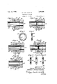
- Figure 1 is a view partly in section, showing a coupling assembled but not set up or tightened.
- Figure 2 is a similar view with the coupling set up. s
- Figure 3 is] an enlarged sectional view of the coupling.
- Figures 4 and 5 are sectional views of a coupling having a slightly different form of compression member.
- Figures 6 and 7 are elevational and sectional views of the compression member shown in Figs. 4 and 5.
- a pipe 11 which, as here shown, telescopes in the shank of the faucet 10, which shank is provided with means to receive and retain with an adjustable engagement a nut 12, the present engaging means being shown as a threaded portion at 13, to receive a threaded coupling nut 12.
- the abutting or opposed faces 14 and 15 of the threaded shank 13 and the nut 12 are dished or inclined away from each other from their perimeters toward their centers, this inclination or dish being shown in the present instance as a plain coned surface, although the faces 14 and 15 might be otherwise formed, as, for example, curved.
- a ring 16 Between the faces 14 and 15 and surrounding the member 11 is a ring 16, preferably a continuous ring, as shown, of a size to slipreadily over the end of the member 11.
- the ring 16 may be of different shape in cross-sections, as will be apparent from the several forms shown, for illustrative purposes, in the drawings.
- It may be round, elliptical, multi-lateral, as illustrated, or, as shown in Figures 4, 5, 6 and 7 of substantially round form with its under periphery flattened somewhat to give a biting, penetrating or displacing edge 17,.
- the compression nut in the various embodiments shown is provided with an expansion chamber at its rear end within WlllOll the compression ring 16 is disposed for expansion in a radial direction only, the peripheral wall of the expansion chamber compelling constriction of the ring inwardly alon radial lines only against the member or pipe 11.
- the compression member or ring 16 will be made of a metal which will flow without fracture and of a degree of hardness which will compress and indent the member or pipe 11. It will be observed that this compression ring in all of the forms shown, is of unequal dimensions in cross section, the cross sectional axes being of unequal length and the axis of a greater length being disposed in a plane perpendicular to the central longitudinal axis of the ring. This gives a preformation which leads itself naturally to expansion in radial lines only, and the angular indenting projections at the inner periphery of the ring are, by reason of this/ formation, sunk quickly and securely into the metal of the member about which the ring is constricted.
- the faucet 10 having the threaded shank, the pipe 11, and the nut 12, are generally of the same construction as heretofore idescribed.
- the opposed walls 18 and 19 of the shank and nut are, however, preferably perpendicular to the axis of the pipe and shank and provided with projections, preferably in the form of wedging annuli 20, which, when the, parts are setup or drawn together, as by't e threaded engagement described, will bite into the compression member 21, which, as here shown, is of flat washer-like form of a size which will fit snugly the bore of the nut 12 so that its outer periphery takes a firm bearing against the inner wall of the nut and has a biting inner periphery and by upsetting the metal of the compression member 21 cause its inner periphery to be forced into .engagement with the pipe 11, as shown in Figure 9.
- a compression member 26 of lnulti-lateral form in cross-section is shown.
- the cross section is, roughly, of a symmetrical diamond or lozenge form, the inner faces sloping to a compression edge 27 while the outer faces slope to a base 28.
- a coupling the combination of a pair of members to be coupled, a third member adjustably engaging one of said members the construction described, which may obviously be varied by the exercise of mechamto be coupled, a preformed compression ring between said engaged members and-in gripping relation to one of said pair of members, said compression member being adapted to be distorted and that portion of said compression member in direct contact with the member to be coupled forced in radial lines only against the last mentioned memld er when the engaged members are moved relatively to each other.
- a preformed compression ring for compression couplings having unequal cross sectional axes,-the major axis lying in a plane substantially perpendicular to the central longitudinal axis of the ring, said ring having an indenting rib on its inner periphery.
- a reformed compression ring for compression couplings having unequal cross sectional axes, the major axis lylng in a plane substantially perpendicular to the central longitudinal axis of the ring, said ring having a plurality of indenting ribs on its inner periphery.
- a preformed compression ring for compression couplings having unequal cross sectional axes, the major axis lying in a plane substantially perpendicular to the central longitudinal axis of the ring, said ring having converging sides to form an indenting rib on its inner periphery.
Description
Nov. 18, 1924. I 1,516,396
P. MUELLER ET AL COMPRESSION COUPLING Filed Jan. 9, 1920 2 Sheets$heet l Innu lrwenfizrs: .171119'0 25266266?" and 5772,5027, 0.50/aacrznanru Nov, 18, 1924. P. MUELLER ET AL COMPRESSION COUPLING Filed Jan. 9. 1.920
2 Sheets-Sheet. 2
1&4. I 12 E86 7 Invenfors: .Pkzllz 'vflueller and down.
Patented Nov. 18, 1924.
UNITED STATES 1,516,396 PATENT OFFICE.
PHILIP MUELLER- AND ANTON C. SGHUERMANN, OF DECATUR, ILLINOIS, ASSIGNORS TO ADOLPH. MUELLER, TRUSTEE, OF DECATUR, ILLINO'IS COMPRESSION COUPLING.
Application filed January 9, 1920. Serial No. 350,455.
To all whom it may concern:
Be it known that we, PHILIP MUELLER and ANTON C. SGHUERMANN, citizens of the United States, residing at Decatur, in the county of Macon and State of Illinois, have invented new and useful Improvements in Compression Couplings, of which the following is a specification.
The present invention relates to couplings and more particularly to what are known as pipe couplin s and has for its object to provide a coup ing in which, without the use of packing as ordinarily used, a fluid tight joint can be formed and in which,
' additionally, the parts are locked against accidental displacement, although free to be uncoupled if the coupling in it be taken Certain other forms of the invention are embodied in applicants co-pending application, Serial No. 354,504, filed January 27, 1920.
In the present disclosure, we show and describe the invention as applied to a faucet coupling, but it will be understood that it is applicable to any class of work to which it is adaptable, and the present disclosure is not, therefore, restrictive of the invention, but merely illustrative of one embodiment thereof.
In order that the invention may be clear to those skilled in the art, we have illustrated one embodiment of it in the accompanying drawings, in which:
Figure 1 is a view partly in section, showing a coupling assembled but not set up or tightened.
Figure 2 is a similar view with the coupling set up. s
Figure 3 is] an enlarged sectional view of the coupling.
Figures 4 and 5 are sectional views of a coupling having a slightly different form of compression member.
Figures 6 and 7 are elevational and sectional views of the compression member shown in Figs. 4 and 5.
members or devices to be coupled. The
other member to be coupled is arbitrarily shown as a pipe 11, which, as here shown, telescopes in the shank of the faucet 10, which shank is provided with means to receive and retain with an adjustable engagement a nut 12, the present engaging means being shown as a threaded portion at 13, to receive a threaded coupling nut 12.
Obviously the telescoping of the parts is incidental to the illustrative disclosure herein used and not in limitation of the invention. Furthermore, interengaging means other than the threaded means shown might be utilized.
The abutting or opposed faces 14 and 15 of the threaded shank 13 and the nut 12 are dished or inclined away from each other from their perimeters toward their centers, this inclination or dish being shown in the present instance as a plain coned surface, although the faces 14 and 15 might be otherwise formed, as, for example, curved.
' Between the faces 14 and 15 and surrounding the member 11 is a ring 16, preferably a continuous ring, as shown, of a size to slipreadily over the end of the member 11. The ring 16 may be of different shape in cross-sections, as will be apparent from the several forms shown, for illustrative purposes, in the drawings.
It may be round, elliptical, multi-lateral, as illustrated, or, as shown in Figures 4, 5, 6 and 7 of substantially round form with its under periphery flattened somewhat to give a biting, penetrating or displacing edge 17,.
and this form we find very effective and satisfactory.
The parts specified are assembled as shown in Figure 1, and the nut 12, or equivalent member, and the shank 12, or equivalent member, are then drawn together by the threaded, or equivalent, engagement described. This drawing together of the members causes their faces 14 and 15 to approach each other and compress the member 16 between them. Owing to the dish or inclination of the faces, compression of the ring 16 uniformly on its outer periphery will cause distortion of ring 16 and compression inwardly, so as to constrict the ring 16 about the member 11. Preferably such constriction will be carried to such a point that the member 11 will be indented, as shown in disclosure, is arbitrarily used as one of the I .and securely locked against accidental separation.
It will be observed that the compression nut in the various embodiments shown is provided with an expansion chamber at its rear end within WlllOll the compression ring 16 is disposed for expansion in a radial direction only, the peripheral wall of the expansion chamber compelling constriction of the ring inwardly alon radial lines only against the member or pipe 11.
The compression member or ring 16 will be made of a metal which will flow without fracture and of a degree of hardness which will compress and indent the member or pipe 11. It will be observed that this compression ring in all of the forms shown, is of unequal dimensions in cross section, the cross sectional axes being of unequal length and the axis of a greater length being disposed in a plane perpendicular to the central longitudinal axis of the ring. This gives a preformation which leads itself naturally to expansion in radial lines only, and the angular indenting projections at the inner periphery of the ring are, by reason of this/ formation, sunk quickly and securely into the metal of the member about which the ring is constricted.
In Figs. 8, 9 and 10, a slightly different development of the invention is disclosed.
The faucet 10 having the threaded shank, the pipe 11, and the nut 12, are generally of the same construction as heretofore idescribed. The opposed walls 18 and 19 of the shank and nut are, however, preferably perpendicular to the axis of the pipe and shank and provided with projections, preferably in the form of wedging annuli 20, which, when the, parts are setup or drawn together, as by't e threaded engagement described, will bite into the compression member 21, which, as here shown, is of flat washer-like form of a size which will fit snugly the bore of the nut 12 so that its outer periphery takes a firm bearing against the inner wall of the nut and has a biting inner periphery and by upsetting the metal of the compression member 21 cause its inner periphery to be forced into .engagement with the pipe 11, as shown in Figure 9. I
The disclosure in Figure 10 is very much like that in Figures 8 and 9, except that the compression member 21 is made smaller and is housed within the recessed bore 22 of the shank of the faucet 10, within which recess elements 24 on the inner periphery are prois of elliptical form in cross-section; with its 7 major axis perpendicular to the central longitudinal axis of the ring, this form lending itself readily to compression and a gripping action.
In Figure 13, a compression member 26 of lnulti-lateral form in cross-section is shown. In the particular type disclosed, the cross section is, roughly, of a symmetrical diamond or lozenge form, the inner faces sloping to a compression edge 27 while the outer faces slope to a base 28.
With all of these forms the action is generally the same so far ascompression upon the parts to be coupled is concerned, and by cal skill and still embody the principle of my invention, a fluid-tight joint may be made without the necessity of packing, soldering, brazing or flaring the metal.
We claim:
1. In a coupling, the combination of a pair of members to be coupled, a third member adjustably engaging one of said members the construction described, which may obviously be varied by the exercise of mechamto be coupled, a preformed compression ring between said engaged members and-in gripping relation to one of said pair of members, said compression member being adapted to be distorted and that portion of said compression member in direct contact with the member to be coupled forced in radial lines only against the last mentioned memld er when the engaged members are moved relatively to each other.
2. In a, coupling, the combination of apair of members to be coupled, a third member adjustably engaging one of said pair of members, a continuous preformed compression ring between said engaged members and in gripping relation to the other of said 7 pair of members, the opposed faces of said engaged members in radial. lines only being of such conformation as to compress a portion of said compression rmg against one of said engaged members when said engaged members are moved relatively to each other.
3. In a coupling, thecombination ofapair of members to be coupled, a third member adjustably engaging one of said pan of members, a continuous preformed compression ring between said engaged members and in gripping relation to the other of sa d pair of members, the opposed faces of said engaged members being of such conformaof said compression ring about one of said members in radial lines only when said engaged members are drawn together.
4. In a coupling, the combination of two tion as lo constrict and compress a portion telescoping members, a third member adjusting the other of said telescoping members,
and compressing means on said engaged members to constrict and compress a portion of said compression ring against one of said telescoped members in radial lines only when said engaged members are drawn together.
5. In a coupling, the combination of two telescoping members, a third member threaded to, the telescoped member, a continuous preformed compression ring on the telescoping member and between the opposed faces of said third and telescoped members, said opposed faces being so formed as to force a portion of said compression ring inward alon" radial lines only against said telescoping member. V
6. In a coupling, the combination of two telescoping members, a third member threaded to the telescoped member, a continuous preformed compression ring having an indenting inner eriphery mounted on the telescoping mem er and lying-between the opposed faces of said third and telescoped members, said opposed faces being so inclined as to force a portion of said compression ring inward along radial lines only and its indenting inner periphery against and into said telescoping member.
7. In a coupling, the combination of two telescoping pipes, a nut threaded to one of said pipes, a compression ring havin a preformed indenting inner periphery etween the opposed faces of said nut and the outer of said pipes, said opposed faces flaring inwardly in a radial direction toward the inner of said pipes so as to give a V-shaped compression chamber and force a portion of said compression member inward along radial lines only and indent said inner pipe.
8. A preformed compression ring for compression couplings, having unequal cross sectional axes,-the major axis lying in a plane substantially perpendicular to the central longitudinal axis of the ring, said ring having an indenting rib on its inner periphery.
9. A reformed compression ring for compression couplings having unequal cross sectional axes, the major axis lylng in a plane substantially perpendicular to the central longitudinal axis of the ring, said ring having a plurality of indenting ribs on its inner periphery.
10. A preformed compression ring for compression couplings having unequal cross sectional axes, the major axis lying in a plane substantially perpendicular to the central longitudinal axis of the ring, said ring having converging sides to form an indenting rib on its inner periphery.
In testimony whereof we have set our hands.
PHILIP MUELLER. ANTON C. SCHUERMANN.
hereunto
Priority Applications (2)
| Application Number | Priority Date | Filing Date | Title |
|---|---|---|---|
| US350455A US1516396A (en) | 1920-01-09 | 1920-01-09 | Compression coupling |
| US664938A US1595310A (en) | 1920-01-09 | 1923-09-26 | Compression coupling |
Applications Claiming Priority (1)
| Application Number | Priority Date | Filing Date | Title |
|---|---|---|---|
| US350455A US1516396A (en) | 1920-01-09 | 1920-01-09 | Compression coupling |
Publications (1)
| Publication Number | Publication Date |
|---|---|
| US1516396A true US1516396A (en) | 1924-11-18 |
Family
ID=23376796
Family Applications (1)
| Application Number | Title | Priority Date | Filing Date |
|---|---|---|---|
| US350455A Expired - Lifetime US1516396A (en) | 1920-01-09 | 1920-01-09 | Compression coupling |
Country Status (1)
| Country | Link |
|---|---|
| US (1) | US1516396A (en) |
Cited By (3)
| Publication number | Priority date | Publication date | Assignee | Title |
|---|---|---|---|---|
| US5190224A (en) * | 1990-04-05 | 1993-03-02 | Spraying Systems Co. | Quick disconnect nozzle assembly |
| US5421522A (en) * | 1993-09-24 | 1995-06-06 | Bex Engineering Ltd. | Nozzle assembly |
| ES2138490A1 (en) * | 1996-04-22 | 2000-01-01 | Carrion Francisca Lopez | Coupling system for joining tubes and valves |
-
1920
- 1920-01-09 US US350455A patent/US1516396A/en not_active Expired - Lifetime
Cited By (3)
| Publication number | Priority date | Publication date | Assignee | Title |
|---|---|---|---|---|
| US5190224A (en) * | 1990-04-05 | 1993-03-02 | Spraying Systems Co. | Quick disconnect nozzle assembly |
| US5421522A (en) * | 1993-09-24 | 1995-06-06 | Bex Engineering Ltd. | Nozzle assembly |
| ES2138490A1 (en) * | 1996-04-22 | 2000-01-01 | Carrion Francisca Lopez | Coupling system for joining tubes and valves |
Similar Documents
| Publication | Publication Date | Title |
|---|---|---|
| US1595310A (en) | Compression coupling | |
| US2211856A (en) | Pipe coupling | |
| US3092404A (en) | Packed screw threaded gland type tube coupling for thin walled tubing | |
| US3215457A (en) | Pipe coupling | |
| US2075947A (en) | Pipe joint | |
| US3711131A (en) | Hose end couplings | |
| US2406488A (en) | Coupling device for pipes or tubes | |
| KR930001669B1 (en) | Cantilever lip conduit coupling menber and assembly | |
| US1738915A (en) | Pipe coupling | |
| JPH05126285A (en) | Tube coupling | |
| US2301280A (en) | Sealing means | |
| US5658025A (en) | Flare-tube assembly | |
| US1957605A (en) | Pipe coupijng | |
| US10352485B2 (en) | Pipe connecting device | |
| US2863678A (en) | Coupling for double-flared tubes | |
| US2676781A (en) | Double fluid seal valve | |
| US1516396A (en) | Compression coupling | |
| US1858136A (en) | Coupling | |
| US2320812A (en) | Conduit and coupling therefor | |
| US5997050A (en) | Double cone coupling nipple of a steel tubing and method of making same | |
| US2829673A (en) | Pipe unions | |
| US2531401A (en) | Pipe coupling | |
| US2455667A (en) | Coupling for high-pressure tubing | |
| US3458220A (en) | Fluid couplings | |
| US1959607A (en) | Threadless pipe coupling |