US1536070A - Can opener - Google Patents
Can opener Download PDFInfo
- Publication number
- US1536070A US1536070A US707925A US70792524A US1536070A US 1536070 A US1536070 A US 1536070A US 707925 A US707925 A US 707925A US 70792524 A US70792524 A US 70792524A US 1536070 A US1536070 A US 1536070A
- Authority
- US
- United States
- Prior art keywords
- lever
- base
- container
- cutting
- head
- Prior art date
- Legal status (The legal status is an assumption and is not a legal conclusion. Google has not performed a legal analysis and makes no representation as to the accuracy of the status listed.)
- Expired - Lifetime
Links
- 238000005520 cutting process Methods 0.000 description 17
- 238000010276 construction Methods 0.000 description 4
- 239000002184 metal Substances 0.000 description 2
- 230000000994 depressogenic effect Effects 0.000 description 1
- 210000005069 ears Anatomy 0.000 description 1
- 238000004519 manufacturing process Methods 0.000 description 1
- 238000000465 moulding Methods 0.000 description 1
- 230000010355 oscillation Effects 0.000 description 1
- 230000000149 penetrating effect Effects 0.000 description 1
- 230000000630 rising effect Effects 0.000 description 1
Images
Classifications
-
- B—PERFORMING OPERATIONS; TRANSPORTING
- B67—OPENING, CLOSING OR CLEANING BOTTLES, JARS OR SIMILAR CONTAINERS; LIQUID HANDLING
- B67B—APPLYING CLOSURE MEMBERS TO BOTTLES JARS, OR SIMILAR CONTAINERS; OPENING CLOSED CONTAINERS
- B67B7/00—Hand- or power-operated devices for opening closed containers
- B67B7/30—Hand-operated cutting devices
Definitions
- the object of this invention is to provide an improved construction for a can opener, whereby a container or can may be held rigidly in a given position during the operation of cutting an'arcuatc slit in one end thereof.
- a further object of this invention is to provide improved means for adjusting the can opening appliances to containers or cans of varying heights.
- a further object of this invention is to provide improved means for cooperatively associating a holding lever and a cutting lever.
- a further object of this invention is to provide improved means for holdinga container or can against rotation by frictional engagement with a serrated base.
- a further object. of this invention is to provide a base with a tapering serrated socket, adapted to accommodate and engage containers or cans of varying dimensions.
- a furtherobject of this invention is to provide an improved construction of and means for mounting a center pin.
- My invention consists in the. construction
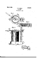
- Figure 1 is a plan of the complete device in position for practical use.
- Figure 2 is a side elevation of the same, a container therein being shown partly in section.
- Figure 3 is a diametrical section of the base member of the device alone.
- the numeral 10 designates a base member, preferably formed of metal by moulding of considerable thickness, and generally circular in plan view.
- Apertured cars 11 are formed on and radiate from the lower portion of the base 10, and are adapted to re ceive screws whereby to secure said base to a support such as a bench or table.
- An car 12, of substantially the same thickness as the base, is formed thereon. and extended radially therefrom.
- the base 10 is formed with a central tapering opening of greater dimension at its top than at its bottom, generally prevent rotation thereof.
- a post 14 is mounted in an upright opening 1n the car 12 and is secured by a set screw 15.
- the post 14 is partly circular and partly angular in cross section (Fig. 1), at least throughout the major por tion of its length, although the lower end thereof may be circular and the hole in which it fits in the car 12 may also be circular for convenience in manufacture.
- the forked bracket 16 is mounted slidingly on A clamping bolt 17 is mounted in registering holes in the arms of the fork and c2;- tends across the plane face of the post 1 1 and is provided with'a wing-nut 18 on its threaded end.
- the forked bracket 16 is formed with a lug 19 on one side, adapted to be engaged by the head of the bolt 17 and
- the inner end portion of the bracket 16 also is forged and a holding lever 20 has one end portion extended within the said inner end fork and pivoted therein by means of a rivet 21.
- the pivot end portion of the holding lever 20 is curved downwardly, as shown, so that the axis of oscillation of said lever may be lower relatively to the plane of the lever.
- a handle 22 is mounted on and extends sub stantially at right angles upwardly from the outer end portion of the holding lever 20, by means of which said lever and associated elements may be moved relative to the bracket 16.
- a cent-er pin 23 is mounted through the central portion of the holding lever 20. It is formed with a conical penetrating point portion 24, having a shoulder at its base.
- a cutting lever 25 is pivoted at one end on the center pin 28, parallel and in contact with the shoulder at the base of the point portion 24, and a washer or bushing 26 is interposed between the end portion of the cutting lever and the central portion of the holding lever 20.
- a washer 27 and nut connecting the center pin, cutting lever and holding lever.
- the inner or pivoted end portion of the cutting lever 25 is ofl -set downwardly relative to the body of said lever to compensate for the depressed arrangement of a head; 29 of the can or C011? tainer 13 relative to its wall, so that in use said oflset portion may approximate closely to or contact with said head while the body of the cutting lever rides on therim or the wall.
- the cutting lever is or greater length than, and extends radially beyond, the handle end of the holding lever 20, in order that said cutting lever may he manipulated through an arc beneath said handle end.
- a longitudinal slot 30 and a knife 31 is slidingly and mni-rotatively mounted in said slot and is secured to said lever by a washer 32 and nut 33 superposed relative to the lever.
- the cutting kni te i-ll is formed to move longitudinally of the slot 30, to accommodate its location to containens or cans 13 of varying diameters.
- the base 10 is secured to a support; a container 13 mounted in the tapering hole in the base with its lower rim in contact with the serrations thereof; and the bracket 16 is adj us'ted altit-udinallgv on the post 13 and secured hy manipulation of the wing-nut 18.
- the cutting lever and holding lever are elevated manually. AJlfter the preliminary adjustn'ients are made the holding); lever is moved downwardly, carrying thecutting lever with it, the point 2% is forced through the central portion of the head 29 of the container, andthe knife 31 is likewise forced through said head adjacent to the wall of the container.
- the holding lever is heldhy one hand of the operator grasping the handle 22, and applies pressure to the container, while the cutting lever is moved through an are by the other hand of the operator, in
- I clainr as my invention l.
- A. can opener con'iprising a base adapted to he securedi to. a support and formed with a lirustun'i shaped central opening, hav ing a. serratedwvalli adapted; to receive a container, a post rising tromi said. base, a bracket adjustahly mounted on said. post. a holding lever hinged to. said bracket. a center pin mounted. in the central portion o'li said holding lever and adapted lo. penetrate the head of said!
- a base In a can opener, a base, "formed with apertured. ears, wl'ierehy it can he secured to a support and also formed with a trustun'i-shaped central socket, having a serrated wallfadapted to engage therim o l a container mounted insaid socket.
Description
Patented May 5, 1925.
GEORGE W. BRIGHT, 0F DENVER, COLORADO.
can ornnnn.
Application filed April 21, 1924. Serial No. 707,925.
To all whom it may concern:
Be itknownthat I, GEORGE BRIGHT,
a citizen of. theUnited States of America,
and resident of the city and county of Denver, Colorado, have invented a new and useful Can Opener, of which the following is a specification.
The object of this invention is to provide an improved construction for a can opener, whereby a container or can may be held rigidly in a given position during the operation of cutting an'arcuatc slit in one end thereof. A further object of this invention is to provide improved means for adjusting the can opening appliances to containers or cans of varying heights.
A further object of this invention is to provide improved means for cooperatively associating a holding lever and a cutting lever.
A further object of this invention is to provide improved means for holdinga container or can against rotation by frictional engagement with a serrated base.
A further object. of this invention is to provide a base with a tapering serrated socket, adapted to accommodate and engage containers or cans of varying dimensions.
A furtherobject of this invention is to provide an improved construction of and means for mounting a center pin. I
My invention consists in the. construction,
. arrangement and combination of elements hereinafter set forth, pointed out in the claims andillustrated by the accompanying drawing, in which Figure 1 is a plan of the complete device in position for practical use. Figure 2 is a side elevation of the same, a container therein being shown partly in section. Figure 3 is a diametrical section of the base member of the device alone.
In the construction of the device as shown, the numeral 10 designates a base member, preferably formed of metal by moulding of considerable thickness, and generally circular in plan view. Apertured cars 11 are formed on and radiate from the lower portion of the base 10, and are adapted to re ceive screws whereby to secure said base to a support such as a bench or table. An car 12, of substantially the same thickness as the base, is formed thereon. and extended radially therefrom. The base 10 is formed with a central tapering opening of greater dimension at its top than at its bottom, generally prevent rotation thereof.
of frustum-shape, and the wall of said opening is serrated, thus providing means for engaging a metal container or can 13, mounted therein. The opening in the base 10 is tapered to accommodate containers or cans of varying diameters and within the range thereof, any container or can will be engaged and held against rotation by the serrations. A post 14 is mounted in an upright opening 1n the car 12 and is secured by a set screw 15. The post 14 is partly circular and partly angular in cross section (Fig. 1), at least throughout the major por tion of its length, although the lower end thereof may be circular and the hole in which it fits in the car 12 may also be circular for convenience in manufacture. A
forked bracket 16 is mounted slidingly on A clamping bolt 17 is mounted in registering holes in the arms of the fork and c2;- tends across the plane face of the post 1 1 and is provided with'a wing-nut 18 on its threaded end. The forked bracket 16 is formed with a lug 19 on one side, adapted to be engaged by the head of the bolt 17 and The inner end portion of the bracket 16 also is forged and a holding lever 20 has one end portion extended within the said inner end fork and pivoted therein by means of a rivet 21. The pivot end portion of the holding lever 20 is curved downwardly, as shown, so that the axis of oscillation of said lever may be lower relatively to the plane of the lever. A handle 22 is mounted on and extends sub stantially at right angles upwardly from the outer end portion of the holding lever 20, by means of which said lever and associated elements may be moved relative to the bracket 16. A cent-er pin 23 is mounted through the central portion of the holding lever 20. It is formed with a conical penetrating point portion 24, having a shoulder at its base. A cutting lever 25 is pivoted at one end on the center pin 28, parallel and in contact with the shoulder at the base of the point portion 24, and a washer or bushing 26 is interposed between the end portion of the cutting lever and the central portion of the holding lever 20. A washer 27 and nut connecting the center pin, cutting lever and holding lever. The inner or pivoted end portion of the cutting lever 25 is ofl -set downwardly relative to the body of said lever to compensate for the depressed arrangement of a head; 29 of the can or C011? tainer 13 relative to its wall, so that in use said oflset portion may approximate closely to or contact with said head while the body of the cutting lever rides on therim or the wall. The cutting lever is or greater length than, and extends radially beyond, the handle end of the holding lever 20, in order that said cutting lever may he manipulated through an arc beneath said handle end. The cuttinglever ZS-is termed with. a longitudinal slot 30 and a knife 31 is slidingly and mni-rotatively mounted in said slot and is secured to said lever by a washer 32 and nut 33 superposed relative to the lever. The cutting kni te i-ll is formed to move longitudinally of the slot 30, to accommodate its location to containens or cans 13 of varying diameters.
In practical use the base 10 is secured to a support; a container 13 mounted in the tapering hole in the base with its lower rim in contact with the serrations thereof; and the bracket 16 is adj us'ted altit-udinallgv on the post 13 and secured hy manipulation of the wing-nut 18. During this operation the cutting lever and holding lever are elevated manually. AJlfter the preliminary adjustn'ients are made the holding); lever is moved downwardly, carrying thecutting lever with it, the point 2% is forced through the central portion of the head 29 of the container, andthe knife 31 is likewise forced through said head adjacent to the wall of the container. The holding lever is heldhy one hand of the operator grasping the handle 22, and applies pressure to the container, while the cutting lever is moved through an are by the other hand of the operator, in
opposite directions, to theend of forming an arcuate sl-it 34. in the head. Then the holding lever and cutting lever are elevated to av plane substantially perpendicular "to the lease, the cut out portion of the head 29 is disengaged from the point 24k and knife 31 and the opened can or container is removed; from the base. The length of the center point 2% is such that when the love are raised atter the cutting operation. is completed said. point tends to elevate the cut out: portion of the head and. presents thecam or container to. the operator in opened condition.
I clainr as my invention l. A. can opener con'iprising a base adapted to he securedi to. a support and formed with a lirustun'i shaped central opening, hav ing a. serratedwvalli adapted; to receive a container, a post rising tromi said. base, a bracket adjustahly mounted on said. post. a holding lever hinged to. said bracket. a center pin mounted. in the central portion o'li said holding lever and adapted lo. penetrate the head of said! can or container, a cutting lever pia'otedl at one end on said center pin and extended to an orbit beyond that of tlie 'tiree-end ol the=holding lever, and a knife slidingly mounted on said cutting lever and :ula-pted to penetrate amh cut an arcuate slot in the head oil the container under areuate movement of said cutting lever.
2. In a can opener, a base, "formed with apertured. ears, wl'ierehy it can he secured to a support and also formed with a trustun'i-shaped central socket, having a serrated wallfadapted to engage therim o l a container mounted insaid socket.
Signed at Denver, in the county o't Denver and State of Colorado, this'oth day of January, 102%.
GEORGE W. BRIGHT.
Priority Applications (1)
| Application Number | Priority Date | Filing Date | Title |
|---|---|---|---|
| US707925A US1536070A (en) | 1924-04-21 | 1924-04-21 | Can opener |
Applications Claiming Priority (1)
| Application Number | Priority Date | Filing Date | Title |
|---|---|---|---|
| US707925A US1536070A (en) | 1924-04-21 | 1924-04-21 | Can opener |
Publications (1)
| Publication Number | Publication Date |
|---|---|
| US1536070A true US1536070A (en) | 1925-05-05 |
Family
ID=24843696
Family Applications (1)
| Application Number | Title | Priority Date | Filing Date |
|---|---|---|---|
| US707925A Expired - Lifetime US1536070A (en) | 1924-04-21 | 1924-04-21 | Can opener |
Country Status (1)
| Country | Link |
|---|---|
| US (1) | US1536070A (en) |
Cited By (1)
| Publication number | Priority date | Publication date | Assignee | Title |
|---|---|---|---|---|
| US5403053A (en) * | 1994-01-03 | 1995-04-04 | Zareck; Mark A. | Can opening and liquid expelling apparatus |
-
1924
- 1924-04-21 US US707925A patent/US1536070A/en not_active Expired - Lifetime
Cited By (1)
| Publication number | Priority date | Publication date | Assignee | Title |
|---|---|---|---|---|
| US5403053A (en) * | 1994-01-03 | 1995-04-04 | Zareck; Mark A. | Can opening and liquid expelling apparatus |
Similar Documents
| Publication | Publication Date | Title |
|---|---|---|
| US1858144A (en) | Jar holder | |
| US1536070A (en) | Can opener | |
| US1779306A (en) | Valve-stem lock-replacing tool | |
| US1923847A (en) | Valve seat cutting device | |
| US2162095A (en) | Can opener | |
| US2364219A (en) | Can opener | |
| US1354399A (en) | Can-opener | |
| US1536053A (en) | Can opener | |
| US2839221A (en) | Device for tapping under pressure a gas containing liquid from a bottle or a can, for instance beer | |
| US2465442A (en) | Phonograph needle sharpener | |
| US536045A (en) | Reloading-tool for cartridges | |
| US1324586A (en) | Ertitt-jab | |
| US513392A (en) | Apparatus for refitting stop-valves | |
| US1281588A (en) | Adjustable oil-spout. | |
| US3589420A (en) | Nut cracker | |
| US535021A (en) | Tool-holder and rest therefor | |
| US476164A (en) | Can-opener | |
| US1517955A (en) | Can opener | |
| US1818291A (en) | Vise | |
| DE595703C (en) | Carrying device, especially for thermos flasks, on bicycles | |
| US2656598A (en) | Can opener | |
| US2647674A (en) | Bottle-corking machine | |
| US3218837A (en) | Double-flare die for tube flaring tool | |
| US2505517A (en) | Pivoted cam jar cap wrench | |
| US1331437A (en) | Can-opener |