US16853A - Machine fob - Google Patents
Machine fob Download PDFInfo
- Publication number
- US16853A US16853A US16853DA US16853A US 16853 A US16853 A US 16853A US 16853D A US16853D A US 16853DA US 16853 A US16853 A US 16853A
- Authority
- US
- United States
- Prior art keywords
- clamps
- cutters
- frame
- metal
- lever
- Prior art date
- Legal status (The legal status is an assumption and is not a legal conclusion. Google has not performed a legal analysis and makes no representation as to the accuracy of the status listed.)
- Expired - Lifetime
Links
- 238000005452 bending Methods 0.000 description 24
- 239000002184 metal Substances 0.000 description 22
- 229910052751 metal Inorganic materials 0.000 description 22
- 150000001875 compounds Chemical class 0.000 description 14
- 238000005520 cutting process Methods 0.000 description 6
- 210000000088 Lip Anatomy 0.000 description 4
- 230000001154 acute Effects 0.000 description 2
- 239000005018 casein Substances 0.000 description 2
- 235000021240 caseins Nutrition 0.000 description 2
- 230000000266 injurious Effects 0.000 description 2
- 230000036633 rest Effects 0.000 description 2
- 238000000926 separation method Methods 0.000 description 2
Images

Classifications
-
- B—PERFORMING OPERATIONS; TRANSPORTING
- B21—MECHANICAL METAL-WORKING WITHOUT ESSENTIALLY REMOVING MATERIAL; PUNCHING METAL
- B21D—WORKING OR PROCESSING OF SHEET METAL OR METAL TUBES, RODS OR PROFILES WITHOUT ESSENTIALLY REMOVING MATERIAL; PUNCHING METAL
- B21D15/00—Corrugating tubes
- B21D15/04—Corrugating tubes transversely, e.g. helically
- B21D15/06—Corrugating tubes transversely, e.g. helically annularly
-
- B—PERFORMING OPERATIONS; TRANSPORTING
- B21—MECHANICAL METAL-WORKING WITHOUT ESSENTIALLY REMOVING MATERIAL; PUNCHING METAL
- B21H—MAKING PARTICULAR METAL OBJECTS BY ROLLING, e.g. SCREWS, WHEELS, RINGS, BARRELS, BALLS
- B21H1/00—Making articles shaped as bodies of revolution
- B21H1/14—Making articles shaped as bodies of revolution balls, rollers, cone rollers, or like bodies
Definitions
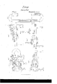
- FIG. 5 is a vertical, central and longitudinal section of the machine, such section being taken so as to represent the compound bending lever as moved backward and having its lever arm raised into a vertical position.
- A denotes the cutter frame
- B exhibits the frame for supporting and carrying the clamps and bending rollers.
- Each of these frames is formed somewhat like the letter U, except in respect to the frame A, one part a, of said frame extending beyond the other part, b, thereof, as shown in Figs. l, 2 and 6, and for the purpose of Vreceiving upon it, and support-ing the frame B, which is placed thereon as shown in the drawings.
- Figs. 6 and 7 represent separate top views of the frames A, B, as they appear when divested of the mechanism applied to them. While the frame A, rests on three legs C, C, C, the frame B, is upheld by said frame A, and by a single leg I), extending down from it as shown in Fig. 2. Slots c, c, and CZ, are made through the frames A, and B, as seen in Figs. 6 and 7, the two frames being held together by two clamp screws and nuts as shown at E, E, in Figs. l and 5, the latter screw F, being made to pass through a sliding or bearing carriage G, arranged on the frame B, as seen in Figs. l and 5.
- the front parts or arms of the two frames A, and B are entirely disconnected, the two frames being connected by their rearvarms or parts and the connections being of such a nature as to permit the frame B, to be moved longitudinally on the frame A, Ain order to adjust the distance of the axis of the clamps from the cutters, as occasion may require, the said clamps and cutters being shown ⁇ at H, I, and K, L.
- the clamp I-I is carried by a rotary shaft e, on which there is a crank, j'. So in regard to the clamp, I, it is supported in the usual way upon a rotary shaft, g, which is moved or forced toward the shaft, e, by power acting through a cam lever, 7L, arranged as shown in Figs. l and 3.
- the clamp I has to be forced with great power toward the clamp H, it does no-t in my machine spring the cutters apart from one another, ⁇ as is the casein other machines, where the clamp frame is so aiiixed tothe cutter frame 'as to cause such a separat-ion of the cutters to occur during the operation of ccnlining a sheet of metal between the clamps.
- the cutters are moved asunder or their true relations disturbed, their operation on the metal will be eifected more or less injuriously.
- the bending rollers which are for the purpose of turning down the circular edge of the disk of metal after it has been cut from a sheet, are shown at M, N, C, the innerl of said rollers, viz., that marked M, being aflixed to an auxiliary rotary shaft, z', carrying a crank 7c, on its outer end, as shown in Figs. l, and 2.
- the roller M may be put in rotation so as to cause the disk to be revolved by power acting at its circumference, instead of near its center it being customary in most other machines of a like nature, to rotate the disks by revolving the clamps.
- the other rollers, N, and O are carried by a compound or jointed lever, I), the same consisting of a bent lever, Z, hinged or jointed to an arm, m, that turns horizontally on a screw pin, n, screwed into some one of a series of screw holes, o, 0, 0, arranged in the sliding carriage, Gr, as seen in Fig. l.
- the object of such series of screw holes is to enable the roller, O, carried by the arm m, to be adjust-ed in its angular position with reference to the plane of the roller M.
- the roller, O, is carried by the lesser arm of the lever Z, it being arranged with respect to the same as shown in Fig. 5.
- each of the said bending rollers is made frusto conical and in other respects as represented in the drawings.
- the sheet of metal while being cut in the form of a disk, is rotated by power applied to the crank f.
- the bending down of the edge of the disk is eiiiected by the action of the bending rollers, the workman or attendant operating the compound lever with his left hand, while with his right hand he turns the crank of the shaft of the roller M.
- a scale of divisions may be applied 'to the frame, A, as seen at S, the same being for convenience of adjustment of the distance between the clamps and cutters.
Description
`"UNITED STATES PATENT CFFICE.
ELLIOT SAVAGE, OF EAST BERLIN, CONNECTICUT.
MACHINE FOR CUTTING AND BENDING SHEET METAL.
Specification of letters Patent N o. 16,853, dated March 17, 18157.
To all whom may concern.'
Be it known that I, ELLIOT SAVAGE, of East Berlin, in the county of Hartford and State of Connecticut, have invented an Improved Machine for Cut-ting a Circular Plate from a Sheet of Metal and for Bending the Edge of said Plate; and I do hereby declare that the same is fully described and represented in the following specification and the accompanying drawings, of which- Figure l, denotes a top view of the said machine; Fig. 2, a front elevation of it. Fig. 3, a rear elevation. Fig. 4:, an inner side view of the movable compound lever and its bending rollers, the same being hereinafter, explained. Fig. 5, is a vertical, central and longitudinal section of the machine, such section being taken so as to represent the compound bending lever as moved backward and having its lever arm raised into a vertical position. In these drawings, A, denotes the cutter frame, while, B, exhibits the frame for supporting and carrying the clamps and bending rollers. Each of these frames is formed somewhat like the letter U, except in respect to the frame A, one part a, of said frame extending beyond the other part, b, thereof, as shown in Figs. l, 2 and 6, and for the purpose of Vreceiving upon it, and support-ing the frame B, which is placed thereon as shown in the drawings.
Figs. 6 and 7 represent separate top views of the frames A, B, as they appear when divested of the mechanism applied to them. While the frame A, rests on three legs C, C, C, the frame B, is upheld by said frame A, and by a single leg I), extending down from it as shown in Fig. 2. Slots c, c, and CZ, are made through the frames A, and B, as seen in Figs. 6 and 7, the two frames being held together by two clamp screws and nuts as shown at E, E, in Figs. l and 5, the latter screw F, being made to pass through a sliding or bearing carriage G, arranged on the frame B, as seen in Figs. l and 5.
From the above it will be seen that the front parts or arms of the two frames A, and B, are entirely disconnected, the two frames being connected by their rearvarms or parts and the connections being of such a nature as to permit the frame B, to be moved longitudinally on the frame A, Ain order to adjust the distance of the axis of the clamps from the cutters, as occasion may require, the said clamps and cutters being shown `at H, I, and K, L. The clamp I-I, is carried by a rotary shaft e, on which there is a crank, j'. So in regard to the clamp, I, it is supported in the usual way upon a rotary shaft, g, which is moved or forced toward the shaft, e, by power acting through a cam lever, 7L, arranged as shown in Figs. l and 3.
In respect to the rotary cutters, K, L, they are applied to the frame, A, as shown in the drawings, that is in the nia-nner in which they are generally applied to the bows and frames of like machines for cutting sheet metal into circular disks, the sheet of metal to be out being placed between the clamps, and so that its edge shall come into the bite or angle of the cutting edges of the cutters. As, in order to hold the sheet of metal securely, the clamp I, has to be forced with great power toward the clamp H, it does no-t in my machine spring the cutters apart from one another,` as is the casein other machines, where the clamp frame is so aiiixed tothe cutter frame 'as to cause such a separat-ion of the cutters to occur during the operation of ccnlining a sheet of metal between the clamps. In case, the cutters are moved asunder or their true relations disturbed, their operation on the metal will be eifected more or less injuriously. Therefore I have so constructed the two frames A, and B, and applied them together, that while one may be moved on the other in a longitudinal direction so as to adjust the distance of the clamps from the cutters, the operation of fixing a sheet of metal between the clamps, shall not spring the cutters apart from one another. .y
The bending rollers, which are for the purpose of turning down the circular edge of the disk of metal after it has been cut from a sheet, are shown at M, N, C, the innerl of said rollers, viz., that marked M, being aflixed to an auxiliary rotary shaft, z', carrying a crank 7c, on its outer end, as shown in Figs. l, and 2. By means of said shaft and crank, the roller M, may be put in rotation so as to cause the disk to be revolved by power acting at its circumference, instead of near its center it being customary in most other machines of a like nature, to rotate the disks by revolving the clamps. Under these latter circumstances, the strain and leverage on the disk is very great, so much so, as often to cause it to slip between the clamps, whereby, the surface or surfaces against which they may be in Contact, may become marred, injured or defaced. The other rollers, N, and O, are carried by a compound or jointed lever, I), the same consisting of a bent lever, Z, hinged or jointed to an arm, m, that turns horizontally on a screw pin, n, screwed into some one of a series of screw holes, o, 0, 0, arranged in the sliding carriage, Gr, as seen in Fig. l. The object of such series of screw holes is to enable the roller, O, carried by the arm m, to be adjust-ed in its angular position with reference to the plane of the roller M. The roller, O, is carried by the lesser arm of the lever Z, it being arranged with respect to the same as shown in Fig. 5.
By constructing the compound lever in the manner described, we are enabled not only to turn it horizontally so as to move ythe roller, N, either toward or away from the roller, M, but we may move the roller, O, either toward or away from either or both of said rollers as occasion may require. Each of the said bending rollers is made frusto conical and in other respects as represented in the drawings. In operating with my improved machine, the sheet of metal, while being cut in the form of a disk, is rotated by power applied to the crank f. The bending down of the edge of the disk is eiiiected by the action of the bending rollers, the workman or attendant operating the compound lever with his left hand, while with his right hand he turns the crank of the shaft of the roller M. In this way he can raise a lip on the periphery of the disk, such lip being yeither at a right angle to the plane of the metal disk, or at such an obtuse, or such an acute angle thereto as circumstances may require. A scale of divisions may be applied 'to the frame, A, as seen at S, the same being for convenience of adjustment of the distance between the clamps and cutters.
I do not claim so applying the clamps and cutters to separate frames or a bow and half bow that the cutters jointly may be moved either toward or away from the clamps without any disturbance of the positions of the cutters relatively to one another; but
IVhat I do claim isl. Constructing and arranging the frame which carries the clamps with respect to that which carries the cutters substantially as described, that is so that while the clamps are being forced together or made to seize a plate of metal, they shall not spread the cutters apart.
2. I also claim the mode of constructing the compound lever of the bending rollers, and arranging the rollers thereon, the said compound lever being composed of a bent lever and an arm, and the rollers being applied to them respectively in manner as above explained.
3. I also claim combining with the clamps, their crank shaft, and the bending rollers, the auxiliary crank shaft or equivalent means by which, the bending roller M, may be rotated, independent-ly of force applied through the clamps, and so that the middle of the metallic plate shall not be subjected to injurious strains by the bending rollers.
In testimony whereof, I have hereunto set my signature this thirteenth day of January A. D. 1857.
ELLIOT SAVAGE.
Vitnesses:
GEORGE L. DIcKINsoN, JONATHAN BARNES.
Publications (1)
| Publication Number | Publication Date |
|---|---|
| US16853A true US16853A (en) | 1857-03-17 |
Family
ID=2078835
Family Applications (1)
| Application Number | Title | Priority Date | Filing Date |
|---|---|---|---|
| US16853D Expired - Lifetime US16853A (en) | Machine fob |
Country Status (1)
| Country | Link |
|---|---|
| US (1) | US16853A (en) |
Cited By (6)
| Publication number | Priority date | Publication date | Assignee | Title |
|---|---|---|---|---|
| US20020083075A1 (en) * | 2000-12-22 | 2002-06-27 | Tony Brummel | System and method for a seamless user interface for an integrated electronic health care information system |
| US20020165898A1 (en) * | 2001-05-03 | 2002-11-07 | Joe Duffy | Recipient-determined method for sharing tasks in an advanced electronic messaging/workflow system |
| US20040059714A1 (en) * | 2002-07-31 | 2004-03-25 | Larsen Steven J. | System and method for providing decision support to appointment schedulers in a healthcare setting |
| US20050071195A1 (en) * | 2003-09-30 | 2005-03-31 | Cassel David A. | System and method of synchronizing data sets across distributed systems |
| US20050071194A1 (en) * | 2003-09-30 | 2005-03-31 | Bormann Daniel S. | System and method for providing patient record synchronization in a healthcare setting |
| US20060080140A1 (en) * | 2004-02-09 | 2006-04-13 | Epic Systems Corporation | System and method for providing a clinical summary of patient information in various health care settings |
-
0
- US US16853D patent/US16853A/en not_active Expired - Lifetime
Cited By (6)
| Publication number | Priority date | Publication date | Assignee | Title |
|---|---|---|---|---|
| US20020083075A1 (en) * | 2000-12-22 | 2002-06-27 | Tony Brummel | System and method for a seamless user interface for an integrated electronic health care information system |
| US20020165898A1 (en) * | 2001-05-03 | 2002-11-07 | Joe Duffy | Recipient-determined method for sharing tasks in an advanced electronic messaging/workflow system |
| US20040059714A1 (en) * | 2002-07-31 | 2004-03-25 | Larsen Steven J. | System and method for providing decision support to appointment schedulers in a healthcare setting |
| US20050071195A1 (en) * | 2003-09-30 | 2005-03-31 | Cassel David A. | System and method of synchronizing data sets across distributed systems |
| US20050071194A1 (en) * | 2003-09-30 | 2005-03-31 | Bormann Daniel S. | System and method for providing patient record synchronization in a healthcare setting |
| US20060080140A1 (en) * | 2004-02-09 | 2006-04-13 | Epic Systems Corporation | System and method for providing a clinical summary of patient information in various health care settings |
Similar Documents
| Publication | Publication Date | Title |
|---|---|---|
| US16853A (en) | Machine fob | |
| US3726A (en) | Machine fob shaving- wood | |
| US65745A (en) | John e | |
| US15133A (en) | Machine fob paring | |
| US869270A (en) | Stay-log. | |
| US20918A (en) | foster | |
| US15196A (en) | Method of ttjknibtg tapering- forms | |
| US10906A (en) | Eotaey shingle-machine | |
| US16339A (en) | Method of adjusting circular saws to any required dish | |
| US16108A (en) | photo-lit ho | |
| US16407A (en) | Machine fob sawing hoops | |
| US262896A (en) | fruit parer | |
| US1623A (en) | Machine fob cutting corks | |
| US15772A (en) | Improvement in making brass kettles | |
| US1162A (en) | Mode of regulating- the jaws of leather-crimping machines | |
| US29199A (en) | Stave-machine | |
| US79783A (en) | Improvement in mitrffls-machffles | |
| US10067A (en) | Machine foe rubbing- and polishing leathee | |
| US54750A (en) | Improvement in machines for boring wagon-hubs | |
| US58637A (en) | Improvement in nail-machines | |
| US74982A (en) | Improved planee-ohuck | |
| US16843A (en) | Machine foe paring | |
| US13301A (en) | Machine for turning cylinders of wood | |
| US16105A (en) | Device fob | |
| US4227A (en) | Machiheey fob |