US1731069A - Surgical instrument - Google Patents
Surgical instrument Download PDFInfo
- Publication number
- US1731069A US1731069A US1731069DA US1731069A US 1731069 A US1731069 A US 1731069A US 1731069D A US1731069D A US 1731069DA US 1731069 A US1731069 A US 1731069A
- Authority
- US
- United States
- Prior art keywords
- snare
- forceps
- jaws
- bore
- current
- Prior art date
- Legal status (The legal status is an assumption and is not a legal conclusion. Google has not performed a legal analysis and makes no representation as to the accuracy of the status listed.)
- Expired - Lifetime
Links
- 210000001847 Jaw Anatomy 0.000 description 52
- 210000001519 tissues Anatomy 0.000 description 20
- 210000003811 Fingers Anatomy 0.000 description 14
- 210000002741 Palatine Tonsil Anatomy 0.000 description 14
- 239000011810 insulating material Substances 0.000 description 14
- 210000001367 Arteries Anatomy 0.000 description 4
- 206010018987 Haemorrhage Diseases 0.000 description 4
- 210000003813 Thumb Anatomy 0.000 description 4
- 210000003462 Veins Anatomy 0.000 description 4
- 231100000319 bleeding Toxicity 0.000 description 4
- 230000000740 bleeding Effects 0.000 description 4
- 239000011888 foil Substances 0.000 description 4
- 231100000241 scar Toxicity 0.000 description 4
- 210000004369 Blood Anatomy 0.000 description 2
- 235000002407 Jessenia polycarpa Nutrition 0.000 description 2
- 244000232488 Jessenia polycarpa Species 0.000 description 2
- 210000000826 Nictitating Membrane Anatomy 0.000 description 2
- 241000282941 Rangifer tarandus Species 0.000 description 2
- 229910000639 Spring steel Inorganic materials 0.000 description 2
- 239000008280 blood Substances 0.000 description 2
- 230000001112 coagulant Effects 0.000 description 2
- 238000010586 diagram Methods 0.000 description 2
- 235000017423 hawthorn Nutrition 0.000 description 2
- 210000001699 lower leg Anatomy 0.000 description 2
- 239000000463 material Substances 0.000 description 2
- 239000000203 mixture Substances 0.000 description 2
- 230000035515 penetration Effects 0.000 description 2
- 229920003245 polyoctenamer Polymers 0.000 description 2
- 230000002787 reinforcement Effects 0.000 description 2
- FAPWRFPIFSIZLT-UHFFFAOYSA-M sodium chloride Chemical compound [Na+].[Cl-] FAPWRFPIFSIZLT-UHFFFAOYSA-M 0.000 description 2
- 239000011780 sodium chloride Substances 0.000 description 2
- 239000000243 solution Substances 0.000 description 2
Images


Classifications
-
- A—HUMAN NECESSITIES
- A61—MEDICAL OR VETERINARY SCIENCE; HYGIENE
- A61B—DIAGNOSIS; SURGERY; IDENTIFICATION
- A61B18/00—Surgical instruments, devices or methods for transferring non-mechanical forms of energy to or from the body
- A61B18/04—Surgical instruments, devices or methods for transferring non-mechanical forms of energy to or from the body by heating
- A61B18/12—Surgical instruments, devices or methods for transferring non-mechanical forms of energy to or from the body by heating by passing a current through the tissue to be heated, e.g. high-frequency current
- A61B18/14—Probes or electrodes therefor
- A61B18/1442—Probes having pivoting end effectors, e.g. forceps
-
- A—HUMAN NECESSITIES
- A61—MEDICAL OR VETERINARY SCIENCE; HYGIENE
- A61B—DIAGNOSIS; SURGERY; IDENTIFICATION
- A61B17/00—Surgical instruments, devices or methods, e.g. tourniquets
- A61B17/28—Surgical forceps
- A61B17/29—Forceps for use in minimally invasive surgery
-
- A—HUMAN NECESSITIES
- A61—MEDICAL OR VETERINARY SCIENCE; HYGIENE
- A61B—DIAGNOSIS; SURGERY; IDENTIFICATION
- A61B17/00—Surgical instruments, devices or methods, e.g. tourniquets
- A61B17/30—Surgical pincettes without pivotal connections
-
- A—HUMAN NECESSITIES
- A61—MEDICAL OR VETERINARY SCIENCE; HYGIENE
- A61B—DIAGNOSIS; SURGERY; IDENTIFICATION
- A61B18/00—Surgical instruments, devices or methods for transferring non-mechanical forms of energy to or from the body
- A61B2018/00053—Mechanical features of the instrument of device
- A61B2018/00184—Moving parts
- A61B2018/00196—Moving parts reciprocating lengthwise
Definitions
- the current may be an undamped current of high frequency, for example about 1,000,000 cycles, or a spark gap current of a sutliciently high spark frequency to resemble an undamped current of a suiiiciently high fre- 15 quency to have the property of cutting.
- an undamped current of high frequency for example about 1,000,000 cycles
- a spark gap current of a sutliciently high spark frequency to resemble an undamped current of a suiiiciently high fre- 15 quency to have the property of cutting.
- the active terminal of the source of current was connected to a metallic snare and inactive terminal thereof to a large sheet such as lead foil to be applied to any part of the body, the snare being so insulated that only the cutting port-ion thereof was exposed.
- the sheet of lead foil is done away with and the inactive terminal of the generator is connected to a member which is adapted to engage the tissue which is to be removed.
- This member may be either mounted directly on the snare supporting member or it may be a separate instrument, the latter arrangement being more desirable for certain purposes.
- the new instrument has a number of advantages over the older one, the principal advantage being that the current passes only through the tissue which is to be removed and not through the body. As a result of this feature the scar tissue is very slight and it is possible to positively cook the tissue which is to be removed without affecting the underlying tissue.
- the snare wire remains cold, the cutting action being the result of the electric current itself and not of a heated snare.
- a further advantage of the instrument in which the member to which the inactive terminal is connected is mounted on the snare su' port is that only a single application of t e instrument to the us to be re moved is required.
- the separate tissue engaging member which is preferably in a form of a forceps may also be connected to the active electrode of the generator and used to grasp a gauze sponge which is dipped into a saline solu tion and applied to bleeding parts after the operation.
- the inactive electrode is applied to a portion of the body adjacent the wound, for example on the neck directly opposite the tonsil externally and the current passes through the dampened sponge and seeks the avenue of least resistance which is naturally that point from which the blood is flowing, namely, the artery or vein which is bleeding or oozing. This brings about a direct application of coagulating current down the terminus of the artery or vein needing the same.
- the invention is applicable to instruments for many different kinds of operations, but the nature of the invention will be suiiiciently understood from the accompanying drawing and specification in which I have shown and described two embodiments of the invention suitable for tonsillotomy.
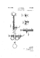
- Fig. 1 shows in side elevation an instrument of the type having a forceps mounted on the snare support itself.
- a wiring diagram is also shown in this figure,
- Fig. 2 is a plan view of the instrument shown in Fig. 1,
- Fig. 3 is a longitudinal section on the line 33 of Fig. 2,
- Fig. 4 is a section on the line l& of Fig. 2,
- Fig. 5 is a section on the line 55 of Fig. 2,
- Fig. 6 is a section on the line 6-6 of Fig. 2,
- Fig. 7 is an elevation of a separate forceps
- Fig 8 is a longitudinal section thereof on the line 8-8 of Fig. 7 and Fig. 9 shows the manner in which the separate forceps is used in combination with an open snare.
- Figs. 1 to 6 21 provided with a lock and drag member 3 which cooperates with depressions 4: in the bar 2 to control the motion of the finger grip or to lock the same.
- One end of the bar 2 is provided with a thumb grip 5 and the other end with.
- a sleeve 6 adapted to receive 'the shank 7 of a supporting member 8 having a bore 9 in which is slidab y received the stem of a metallic snare 10.
- the rear end of the snare is secured in metallic tube 11. in an aperture in the finger grip 1 by means of a set screw 12 having a knurled head 13 of insulating mat rial.
- the member 8 is made of insulating material and the bore 9 is preferably lined with a metallic tube 14 for reinforcement. At its outer end the member 8 has a loop 15 of insulatin material the inner circumference of which is grooved to receive the loop of the snare 9 when in its expanded position.
- the member 8 is provided with a second longitudinal bore 16 which is likewise lined with a metallic tube 17 within which is slidably mounted a metallic forceps composed of a bar 18, a finger grip 19 at one end there of, and a pair of jaws 20 at the other end thereof.
- the jaws 20 are preferably two curved spring steel members secured at one end in a slot 21 in the rod 18.
- the aws 20 are curved so as to normally spread apart and lie in substantial alinement with the sides of the loop 15.
- the sides of the loop 15 are provided with guards 22 which extend over the jaws 20 and cover all but the ends thereof.
- the jaws 20 have stops 20 which abut against the end of tube 17 and limit the motion of the jaws into the tube, l Vhen the jaws are drawn into the bore 16 by pulling on finger grip 19 they are closed together in an obvious manner.
- An electric contact 23 is mounted on the member 18 at the rear end of bore 16.
- This contact consists of an insulated metallic tube 24 adapted to receive a contact point 25 and connected at its inner end to the metallic lining 17 of bore 16.
- An electric contact is also provided on the finger grip 1 consisting of a metallic tube 26 adapted to receive a contact point 27 and connected at its upper end by a wire 28 to the metallic tube 11 in which the end of the snare is secured.
- frequency generator 2-9 capable of producing a cutting current is sup-plied with current from a light socket 20 by wires 31 and 32 in one of which is inserted a foot switch 33.
- the inactive terminal 34 of the generator is connected to the contact point 25 inserted in contact 23.
- the active terminal 36 is connected to contact point 27 inserted in contact 26.
- Figs. 7 to 9 l have shown a separate forceps adapted to be used in connection with an open snare for cases in which all of the tonsil cannot be removed by the first operation with the covered snare.
- This forceps consists of a tubular body 40 of insuhd'ingmaterial lined with a metallic forceps consisting of a rod 42 having secured to one end a pair of resilient jaws 43 as in the instrument previously described.
- the tubes 4*.0 and 41 are provided with a slot 41 1 through which extends the stem 15 of a finger grip 116, which stem is screwed into a threaded hole near the end of the rod 12.
- a thumb grip 17 is mounted on the tube 10 adjacent the rear end thereof.
- the rear end of the tube 11 is open and is adapted to receive a contact point 18.
- the electrical connections are the same with the first described instrument; that is to say, the inactive terminal of the generator 29 is connected to the forceps and the active terminal is connected to the snare.
- the active terminal of the generator is connected to the forceps and the inactive terminal is connected to an electrode which is applied to the external surface of the body adjacent the part being treated.
- an in sulated metallic snare an insulateo metallic forceps, a source of cutting electric current, means for connecting one terminal of said source of current to said snare, and means for connecting the other terminal thereof to said forceps.
- a tube of insulating material In a device of the class described for ren'ioving undesirable tissue, a tube of insulating material, a l'netallic snare slidably mounted in said tube, means for drawing said snare into said tube, an insulated n'letallic member adapted to engage the undesirable tissue, a. source of cutting electric current, means for connecting one terminal of said source of current to said snare, and means for connecting the other terminal thereof to said memlmr.
- an insulated metallic snare In a device of the class des ihed, an insulated metallic snare, a tube of insulating material, a pair of relatively movable jaws connected together at one end and ifQSllliffllllly held apart, the connected ends of said jaws being inserted in said tube, means for drawing said jaws into said tube to close them together, a source of cutting electric current, means for connecting one terminal of said source of current to said snare, and means for connecting the other terminal thereof to said forceps.
- a snare a forceps comprising a pair of relatively movable jaws connected together at one end and resiliently held apart, a supporting body having a bore in which said snare is slid ably mounted and asecond bore into which the connected ends of said jaws are inserted, the loop of said snare and the jaws of said forceps being located at one end of said body adjacent one another, means for drawing said snare into said first mentioned bore, means for drawing the jaws of said forceps into said second bore to close them together, a source of cutting electric current, means for connecting one terminal of said source of current to said snare, and means for connecting the other ter minal thereof to said forceps.
- a forceps comprising a pair of relatively movable jaws connected together at one end and resiliently held apart, a supporting body haw ing a bore in which said snare is slidably mounted and a second bore into which the connected ends of said jaws are inserted, the loop of said snare and the jaws of said forceps being located at one end of said body adjacent one another, said body having a grooved loop of insulating material at the end of said first mentioned bore adapted to receive the loop of said snare in its expanded position, means for drawing said snare into said first mentioned bore, means for drawing the aws of said forceps into said second bore to close them together, a source of cutting electric current, means for connecting one terminal of said source of current to said snare, and means for connecting the other terminal thereof to said forceps.
- a snare a forceps comprising a pair of relatively movable jaws connected together at one end and resiliently held apart, a supporting body having a bore in which said snare is slidably mounted and a second bore into which the connected ends of said jaws are inserted, the loop of said snare and the jaws of said forceps being located at one end of said body adjacent one another, said body having a grooved loop of insulating material at the end of said first mentioned bore adapted to receive the loop of said snare in its expanded position, guards of insulating material projecting laterally from said loop of insulating material and partially covering the jaws of said forceps, means for drawing said snare into said first mentioned bore, means for drawing the awe of said forceps into second here to close them together, a source of cutting electric current, means for connecting one terminal of said source of current to said snare, and means for connecting the other terminal thereof to said forceps.
- a snare a forceps comprising a pair of relatively movable jaws connected together at one end and resiliently held apart, a supporting body having a bore in which said snare is slidably mounted and a second bore into which the connected ends of said jaws are inserted, the loop of said snare and the jaws of said forceps being located at one end of said body adjacent one another, means for drawing said snare into said first mentioned bore, means for drawing the jaws of said forceps into said second bore to close them together, a stop on said forceps adapted to en age the end of said body to limit the motion of said forceps, a source of cutting electric current, means for connecting one terminal of said source of current to said snare, and means for connecting the other terminal thereof to said forceps.
Description
Oct. 8, 1929. HERMAN 1,731,069
SURGICAL INSTRUMENT Filed Jan. 16 1928 3 Sheets-Sheet 1 IN VEN TOR.
FBHerman A TTORNE Y Oct. 8, 1929. F. P. HERMAN SURGICAL INSTRUMENT Filed Jan. 16, 1928 3 Sheets-Sheet 2 INVENTOR. EBHerman ATTORNEYJ Oct. 8, 1929. F. P. HERMAN SURGICAL INSTRUMENT Filed Jan. 16, 1928 3 Sheets-Sheet INVENTOR. ERIIerman AITORNEYS l iiiretaral y i'rfthe form of a. t:
Patented Oct. 8, 1929 UNITED STATES FLORENTINE PETER HERMAN, OF WEST PALM BEACH, FLORIDA SURGICAL INSTRUMENT Apphcation filed January 16, 1928.
10 The current may be an undamped current of high frequency, for example about 1,000,000 cycles, or a spark gap current of a sutliciently high spark frequency to resemble an undamped current of a suiiiciently high fre- 15 quency to have the property of cutting. In
the older instrument the active terminal of the source of current was connected to a metallic snare and inactive terminal thereof to a large sheet such as lead foil to be applied to any part of the body, the snare being so insulated that only the cutting port-ion thereof was exposed.
In the new instrument according to the present application the sheet of lead foil is done away with and the inactive terminal of the generator is connected to a member which is adapted to engage the tissue which is to be removed. This member may be either mounted directly on the snare supporting member or it may be a separate instrument, the latter arrangement being more desirable for certain purposes. The new instrument has a number of advantages over the older one, the principal advantage being that the current passes only through the tissue which is to be removed and not through the body. As a result of this feature the scar tissue is very slight and it is possible to positively cook the tissue which is to be removed without affecting the underlying tissue. During the operation the snare wire remains cold, the cutting action being the result of the electric current itself and not of a heated snare. A further advantage of the instrument in which the member to which the inactive terminal is connected is mounted on the snare su' port is that only a single application of t e instrument to the us to be re moved is required. The ibe r i}s whim-Hi Serial No. 247,202.
serves not only to form an electric contact therewith, but also to grasp the tissue so that no other forceps are needed. This feature is of particular importance in tonsillotomy because of the limited space within which the surgeon has to operate.
The separate tissue engaging member which is preferably in a form of a forceps may also be connected to the active electrode of the generator and used to grasp a gauze sponge which is dipped into a saline solu tion and applied to bleeding parts after the operation. In this case the inactive electrode is applied to a portion of the body adjacent the wound, for example on the neck directly opposite the tonsil externally and the current passes through the dampened sponge and seeks the avenue of least resistance which is naturally that point from which the blood is flowing, namely, the artery or vein which is bleeding or oozing. This brings about a direct application of coagulating current down the terminus of the artery or vein needing the same. The invention is applicable to instruments for many different kinds of operations, but the nature of the invention will be suiiiciently understood from the accompanying drawing and specification in which I have shown and described two embodiments of the invention suitable for tonsillotomy.
Fig. 1 shows in side elevation an instrument of the type having a forceps mounted on the snare support itself. A wiring diagram is also shown in this figure,
Fig. 2 is a plan view of the instrument shown in Fig. 1,
Fig. 3 is a longitudinal section on the line 33 of Fig. 2,
Fig. 4 is a section on the line l& of Fig. 2,
Fig. 5 is a section on the line 55 of Fig. 2,
Fig. 6 is a section on the line 6-6 of Fig. 2,
Fig. 7 is an elevation of a separate forceps,
Fig 8 is a longitudinal section thereof on the line 8-8 of Fig. 7 and Fig. 9 shows the manner in which the separate forceps is used in combination with an open snare.
""iii first to Figs. 1 to 6 21 provided with a lock and drag member 3 which cooperates with depressions 4: in the bar 2 to control the motion of the finger grip or to lock the same. One end of the bar 2 is provided with a thumb grip 5 and the other end with. a sleeve 6 adapted to receive 'the shank 7 of a supporting member 8 having a bore 9 in which is slidab y received the stem of a metallic snare 10. The rear end of the snare is secured in metallic tube 11. in an aperture in the finger grip 1 by means of a set screw 12 having a knurled head 13 of insulating mat rial. The member 8 is made of insulating material and the bore 9 is preferably lined with a metallic tube 14 for reinforcement. At its outer end the member 8 has a loop 15 of insulatin material the inner circumference of which is grooved to receive the loop of the snare 9 when in its expanded position.
The member 8 is provided with a second longitudinal bore 16 which is likewise lined with a metallic tube 17 within which is slidably mounted a metallic forceps composed of a bar 18, a finger grip 19 at one end there of, and a pair of jaws 20 at the other end thereof. The jaws 20 are preferably two curved spring steel members secured at one end in a slot 21 in the rod 18. The aws 20 are curved so as to normally spread apart and lie in substantial alinement with the sides of the loop 15. The sides of the loop 15 are provided with guards 22 which extend over the jaws 20 and cover all but the ends thereof. The jaws 20 have stops 20 which abut against the end of tube 17 and limit the motion of the jaws into the tube, l Vhen the jaws are drawn into the bore 16 by pulling on finger grip 19 they are closed together in an obvious manner.
An electric contact 23 is mounted on the member 18 at the rear end of bore 16. This contact consists of an insulated metallic tube 24 adapted to receive a contact point 25 and connected at its inner end to the metallic lining 17 of bore 16. An electric contact is also provided on the finger grip 1 consisting of a metallic tube 26 adapted to receive a contact point 27 and connected at its upper end by a wire 28 to the metallic tube 11 in which the end of the snare is secured. A high.
frequency generator 2-9 capable of producing a cutting current is sup-plied with current from a light socket 20 by wires 31 and 32 in one of which is inserted a foot switch 33. The inactive terminal 34 of the generator is connected to the contact point 25 inserted in contact 23. The active terminal 36 is connected to contact point 27 inserted in contact 26.
The operation of the instrument is as follows:
The foot switch 33 being off and the snare and forceps being in expanded position the tonsil is worked through the loop 15 and the jaws of the forceps are then drawn in by pulling on finger grip 19 which causes them to grasp the tonsil and form a good electric connection therewith. Simultaneously the snare is drawn up taut and the foot switch is then turned on sending an electric current from the snare through the tonsil to the forceps. This current is of a cutting nature as set forth above and the snare is easily drawn through the base of the tonsil. There is practically no penetration of the underlying tonsil fossa by the current and the resulting scar tissue is therefore very slight.
In Figs. 7 to 9 l have shown a separate forceps adapted to be used in connection with an open snare for cases in which all of the tonsil cannot be removed by the first operation with the covered snare. This forceps consists of a tubular body 40 of insuhd'ingmaterial lined with a metallic forceps consisting of a rod 42 having secured to one end a pair of resilient jaws 43 as in the instrument previously described. The tubes 4*.0 and 41 are provided with a slot 41 1 through which extends the stem 15 of a finger grip 116, which stem is screwed into a threaded hole near the end of the rod 12. A thumb grip 17 is mounted on the tube 10 adjacent the rear end thereof. The rear end of the tube 11 is open and is adapted to receive a contact point 18.
In using this forceps in connection with an open snare the electrical connections are the same with the first described instrument; that is to say, the inactive terminal of the generator 29 is connected to the forceps and the active terminal is connected to the snare. On the other hand, when using the forceps with a gauze sponge above described, the active terminal of the generator is connected to the forceps and the inactive terminal is connected to an electrode which is applied to the external surface of the body adjacent the part being treated.
Having described my invention, 1 claim:
1. In a device of the class described, an in sulated metallic snare, an insulateo metallic forceps, a source of cutting electric current, means for connecting one terminal of said source of current to said snare, and means for connecting the other terminal thereof to said forceps.
'2. In a device of the class described for ren'ioving undesirable tissue, a tube of insulating material, a l'netallic snare slidably mounted in said tube, means for drawing said snare into said tube, an insulated n'letallic member adapted to engage the undesirable tissue, a. source of cutting electric current, means for connecting one terminal of said source of current to said snare, and means for connecting the other terminal thereof to said memlmr.
3. In a device of the class des ihed, an insulated metallic snare, a tube of insulating material, a pair of relatively movable jaws connected together at one end and ifQSllliffllllly held apart, the connected ends of said jaws being inserted in said tube, means for drawing said jaws into said tube to close them together, a source of cutting electric current, means for connecting one terminal of said source of current to said snare, and means for connecting the other terminal thereof to said forceps.
t. In a surgical instrument, a snare, a forceps comprising a pair of relatively movable jaws connected together at one end and resiliently held apart, a supporting body having a bore in which said snare is slid ably mounted and asecond bore into which the connected ends of said jaws are inserted, the loop of said snare and the jaws of said forceps being located at one end of said body adjacent one another, means for drawing said snare into said first mentioned bore, means for drawing the jaws of said forceps into said second bore to close them together, a source of cutting electric current, means for connecting one terminal of said source of current to said snare, and means for connecting the other ter minal thereof to said forceps.
5. In a surgical instrument, a snare, a forceps comprising a pair of relatively movable jaws connected together at one end and resiliently held apart, a supporting body haw ing a bore in which said snare is slidably mounted and a second bore into which the connected ends of said jaws are inserted, the loop of said snare and the jaws of said forceps being located at one end of said body adjacent one another, said body having a grooved loop of insulating material at the end of said first mentioned bore adapted to receive the loop of said snare in its expanded position, means for drawing said snare into said first mentioned bore, means for drawing the aws of said forceps into said second bore to close them together, a source of cutting electric current, means for connecting one terminal of said source of current to said snare, and means for connecting the other terminal thereof to said forceps.
6. In a surgical instrument, a snare, a forceps comprising a pair of relatively movable jaws connected together at one end and resiliently held apart, a supporting body having a bore in which said snare is slidably mounted and a second bore into which the connected ends of said jaws are inserted, the loop of said snare and the jaws of said forceps being located at one end of said body adjacent one another, said body having a grooved loop of insulating material at the end of said first mentioned bore adapted to receive the loop of said snare in its expanded position, guards of insulating material projecting laterally from said loop of insulating material and partially covering the jaws of said forceps, means for drawing said snare into said first mentioned bore, means for drawing the awe of said forceps into second here to close them together, a source of cutting electric current, means for connecting one terminal of said source of current to said snare, and means for connecting the other terminal thereof to said forceps.
7. In a surgical instrument, a snare, a forceps comprising a pair of relatively movable jaws connected together at one end and resiliently held apart, a supporting body having a bore in which said snare is slidably mounted and a second bore into which the connected ends of said jaws are inserted, the loop of said snare and the jaws of said forceps being located at one end of said body adjacent one another, means for drawing said snare into said first mentioned bore, means for drawing the jaws of said forceps into said second bore to close them together, a stop on said forceps adapted to en age the end of said body to limit the motion of said forceps, a source of cutting electric current, means for connecting one terminal of said source of current to said snare, and means for connecting the other terminal thereof to said forceps.
FLORENTINE PETER HEBli EAN.
Publications (1)
| Publication Number | Publication Date |
|---|---|
| US1731069A true US1731069A (en) | 1929-10-08 |
Family
ID=3419061
Family Applications (1)
| Application Number | Title | Priority Date | Filing Date |
|---|---|---|---|
| US1731069D Expired - Lifetime US1731069A (en) | Surgical instrument |
Country Status (1)
| Country | Link |
|---|---|
| US (1) | US1731069A (en) |
Cited By (28)
| Publication number | Priority date | Publication date | Assignee | Title |
|---|---|---|---|---|
| US3903892A (en) * | 1973-05-17 | 1975-09-09 | Olympus Optical Co | Forceps means for removing cellular tissue from the body cavities |
| US3938527A (en) * | 1973-07-04 | 1976-02-17 | Centre De Recherche Industrielle De Quebec | Instrument for laparoscopic tubal cauterization |
| US3955578A (en) * | 1974-12-23 | 1976-05-11 | Cook Inc. | Rotatable surgical snare |
| US3982542A (en) * | 1975-03-12 | 1976-09-28 | Ford John L | Electroresectroscope and method of laparoscopic tubal sterilization |
| US4003380A (en) * | 1974-09-05 | 1977-01-18 | F.L. Fisher | Bipolar coagulation instrument |
| US4011872A (en) * | 1974-04-01 | 1977-03-15 | Olympus Optical Co., Ltd. | Electrical apparatus for treating affected part in a coeloma |
| US4085756A (en) * | 1975-07-09 | 1978-04-25 | Kenneth Weaver | Method and apparatus for performing an electrosurgical procedure |
| US4128099A (en) * | 1976-09-22 | 1978-12-05 | Richard Wolf Gmbh | Single-pole coagulation forceps |
| US4345599A (en) * | 1980-03-20 | 1982-08-24 | Mccarrell Stuart G | Tonsil snare |
| US4619260A (en) * | 1984-11-05 | 1986-10-28 | Magill John W | Tissue-retrieving means for a surgical snare instrument |
| US5460629A (en) * | 1991-02-06 | 1995-10-24 | Advanced Surgical, Inc. | Electrosurgical device and method |
| US5507744A (en) * | 1992-04-23 | 1996-04-16 | Scimed Life Systems, Inc. | Apparatus and method for sealing vascular punctures |
| US5810810A (en) * | 1992-04-23 | 1998-09-22 | Scimed Life Systems, Inc. | Apparatus and method for sealing vascular punctures |
| US6063085A (en) * | 1992-04-23 | 2000-05-16 | Scimed Life Systems, Inc. | Apparatus and method for sealing vascular punctures |
| US20060276783A1 (en) * | 1996-09-20 | 2006-12-07 | Ioan Cosmescu | Multifunctional telescopic monopolar/bipolar surgical device and method thereof |
| USRE40863E1 (en) * | 1992-04-23 | 2009-07-21 | Boston Scientific Scimed, Inc. | Apparatus and method for sealing vascular punctures |
| US7867163B2 (en) | 1998-06-22 | 2011-01-11 | Maquet Cardiovascular Llc | Instrument and method for remotely manipulating a tissue structure |
| US7938842B1 (en) | 1998-08-12 | 2011-05-10 | Maquet Cardiovascular Llc | Tissue dissector apparatus |
| US7972265B1 (en) | 1998-06-22 | 2011-07-05 | Maquet Cardiovascular, Llc | Device and method for remote vessel ligation |
| US7981133B2 (en) | 1995-07-13 | 2011-07-19 | Maquet Cardiovascular, Llc | Tissue dissection method |
| US8241210B2 (en) | 1998-06-22 | 2012-08-14 | Maquet Cardiovascular Llc | Vessel retractor |
| US8366706B2 (en) | 2007-08-15 | 2013-02-05 | Cardiodex, Ltd. | Systems and methods for puncture closure |
| US8372072B2 (en) | 2003-02-04 | 2013-02-12 | Cardiodex Ltd. | Methods and apparatus for hemostasis following arterial catheterization |
| US8435236B2 (en) | 2004-11-22 | 2013-05-07 | Cardiodex, Ltd. | Techniques for heat-treating varicose veins |
| EP2604210A1 (en) * | 2011-12-13 | 2013-06-19 | Covidien LP | Surgical forceps |
| US10172612B2 (en) | 2015-01-21 | 2019-01-08 | Covidien Lp | Surgical instruments with force applier and methods of use |
| US10299770B2 (en) | 2006-06-01 | 2019-05-28 | Maquet Cardiovascular Llc | Endoscopic vessel harvesting system components |
| US10507012B2 (en) | 2000-11-17 | 2019-12-17 | Maquet Cardiovascular Llc | Vein harvesting system and method |
-
0
- US US1731069D patent/US1731069A/en not_active Expired - Lifetime
Cited By (39)
| Publication number | Priority date | Publication date | Assignee | Title |
|---|---|---|---|---|
| US3903892A (en) * | 1973-05-17 | 1975-09-09 | Olympus Optical Co | Forceps means for removing cellular tissue from the body cavities |
| US3938527A (en) * | 1973-07-04 | 1976-02-17 | Centre De Recherche Industrielle De Quebec | Instrument for laparoscopic tubal cauterization |
| US4011872A (en) * | 1974-04-01 | 1977-03-15 | Olympus Optical Co., Ltd. | Electrical apparatus for treating affected part in a coeloma |
| US4003380A (en) * | 1974-09-05 | 1977-01-18 | F.L. Fisher | Bipolar coagulation instrument |
| US3955578A (en) * | 1974-12-23 | 1976-05-11 | Cook Inc. | Rotatable surgical snare |
| US3982542A (en) * | 1975-03-12 | 1976-09-28 | Ford John L | Electroresectroscope and method of laparoscopic tubal sterilization |
| US4085756A (en) * | 1975-07-09 | 1978-04-25 | Kenneth Weaver | Method and apparatus for performing an electrosurgical procedure |
| US4128099A (en) * | 1976-09-22 | 1978-12-05 | Richard Wolf Gmbh | Single-pole coagulation forceps |
| US4345599A (en) * | 1980-03-20 | 1982-08-24 | Mccarrell Stuart G | Tonsil snare |
| US4619260A (en) * | 1984-11-05 | 1986-10-28 | Magill John W | Tissue-retrieving means for a surgical snare instrument |
| US5460629A (en) * | 1991-02-06 | 1995-10-24 | Advanced Surgical, Inc. | Electrosurgical device and method |
| US5507744A (en) * | 1992-04-23 | 1996-04-16 | Scimed Life Systems, Inc. | Apparatus and method for sealing vascular punctures |
| US5810810A (en) * | 1992-04-23 | 1998-09-22 | Scimed Life Systems, Inc. | Apparatus and method for sealing vascular punctures |
| US6063085A (en) * | 1992-04-23 | 2000-05-16 | Scimed Life Systems, Inc. | Apparatus and method for sealing vascular punctures |
| USRE40863E1 (en) * | 1992-04-23 | 2009-07-21 | Boston Scientific Scimed, Inc. | Apparatus and method for sealing vascular punctures |
| US7981133B2 (en) | 1995-07-13 | 2011-07-19 | Maquet Cardiovascular, Llc | Tissue dissection method |
| US7935109B2 (en) | 1996-09-20 | 2011-05-03 | Ioan Cosmescu | Multifunctional telescopic monopolar/bipolar surgical device and method thereof |
| US20100094283A1 (en) * | 1996-09-20 | 2010-04-15 | Ioan Cosmescu | Multifunctional telescopic monopolar/bipolar surgical device and method therefore |
| US20060276783A1 (en) * | 1996-09-20 | 2006-12-07 | Ioan Cosmescu | Multifunctional telescopic monopolar/bipolar surgical device and method thereof |
| US8241210B2 (en) | 1998-06-22 | 2012-08-14 | Maquet Cardiovascular Llc | Vessel retractor |
| US7867163B2 (en) | 1998-06-22 | 2011-01-11 | Maquet Cardiovascular Llc | Instrument and method for remotely manipulating a tissue structure |
| US7972265B1 (en) | 1998-06-22 | 2011-07-05 | Maquet Cardiovascular, Llc | Device and method for remote vessel ligation |
| US9730782B2 (en) | 1998-08-12 | 2017-08-15 | Maquet Cardiovascular Llc | Vessel harvester |
| US8460331B2 (en) | 1998-08-12 | 2013-06-11 | Maquet Cardiovascular, Llc | Tissue dissector apparatus and method |
| US8986335B2 (en) | 1998-08-12 | 2015-03-24 | Maquet Cardiovascular Llc | Tissue dissector apparatus and method |
| US9700398B2 (en) | 1998-08-12 | 2017-07-11 | Maquet Cardiovascular Llc | Vessel harvester |
| US7938842B1 (en) | 1998-08-12 | 2011-05-10 | Maquet Cardiovascular Llc | Tissue dissector apparatus |
| US10507012B2 (en) | 2000-11-17 | 2019-12-17 | Maquet Cardiovascular Llc | Vein harvesting system and method |
| US8372072B2 (en) | 2003-02-04 | 2013-02-12 | Cardiodex Ltd. | Methods and apparatus for hemostasis following arterial catheterization |
| US8435236B2 (en) | 2004-11-22 | 2013-05-07 | Cardiodex, Ltd. | Techniques for heat-treating varicose veins |
| US10299770B2 (en) | 2006-06-01 | 2019-05-28 | Maquet Cardiovascular Llc | Endoscopic vessel harvesting system components |
| US11141055B2 (en) | 2006-06-01 | 2021-10-12 | Maquet Cardiovascular Llc | Endoscopic vessel harvesting system components |
| US11134835B2 (en) | 2006-06-01 | 2021-10-05 | Maquet Cardiovascular Llc | Endoscopic vessel harvesting system components |
| US8366706B2 (en) | 2007-08-15 | 2013-02-05 | Cardiodex, Ltd. | Systems and methods for puncture closure |
| EP2604210A1 (en) * | 2011-12-13 | 2013-06-19 | Covidien LP | Surgical forceps |
| US10390855B2 (en) | 2011-12-13 | 2019-08-27 | Covidien Lp | Surgical forceps |
| US9358069B2 (en) | 2011-12-13 | 2016-06-07 | Covidien Lp | Surgical forceps |
| US8864753B2 (en) | 2011-12-13 | 2014-10-21 | Covidien Lp | Surgical Forceps Connected to Treatment Light Source |
| US10172612B2 (en) | 2015-01-21 | 2019-01-08 | Covidien Lp | Surgical instruments with force applier and methods of use |
Similar Documents
| Publication | Publication Date | Title |
|---|---|---|
| US1731069A (en) | Surgical instrument | |
| US2275167A (en) | Electrosurgical instrument | |
| US3054405A (en) | Electrical fepilator | |
| US2012937A (en) | Electrical caponizing forceps | |
| US2050904A (en) | Electric hemostat or cautery | |
| US4370980A (en) | Electrocautery hemostat | |
| US2888927A (en) | Method and apparatus for removal of superfluous hair | |
| US2541246A (en) | Surgical instrument | |
| CN105246424B (en) | Combine electrosurgery device | |
| US702472A (en) | Surgical forceps. | |
| US8647342B2 (en) | Surgical apparatus for tissue sealing and cutting | |
| US4706667A (en) | Electro surgical high frequency cutting instrument | |
| US4311143A (en) | Apparatus for resecting tissue inside the body cavity utilizing high-frequency currents | |
| US9247983B2 (en) | Medical instrument and method of use | |
| US2840082A (en) | Elastic band expanding device | |
| US2120598A (en) | Electrical cutting instrument | |
| US2114695A (en) | Forceps | |
| CN105286992A (en) | Combination electrosurgical device | |
| SE8504485L (en) | BIPOLATED ELECTRICAL SURGICAL TOOL | |
| CN108882958A (en) | The grasping of microsurgery precision and diathermy clamp and diathermy cutter device for intraocular surgery | |
| US3308823A (en) | Apparatus for inoculation against smallpox and the like having means for vibrating and heating a needle | |
| US1717480A (en) | Cautery electrode for desiccation surgery | |
| US1639996A (en) | Diathermy knife | |
| EP3389531B1 (en) | An electrosurgical device | |
| JP2011523874A (en) | Electrosurgical device with safety unit |