US1851538A - Forced feed tubular dope bar - Google Patents
Forced feed tubular dope bar Download PDFInfo
- Publication number
- US1851538A US1851538A US704074A US70407424A US1851538A US 1851538 A US1851538 A US 1851538A US 704074 A US704074 A US 704074A US 70407424 A US70407424 A US 70407424A US 1851538 A US1851538 A US 1851538A
- Authority
- US
- United States
- Prior art keywords
- dope
- bar
- forced feed
- tube
- slot
- Prior art date
- Legal status (The legal status is an assumption and is not a legal conclusion. Google has not performed a legal analysis and makes no representation as to the accuracy of the status listed.)
- Expired - Lifetime
Links
Images

Classifications
-
- D—TEXTILES; PAPER
- D06—TREATMENT OF TEXTILES OR THE LIKE; LAUNDERING; FLEXIBLE MATERIALS NOT OTHERWISE PROVIDED FOR
- D06B—TREATING TEXTILE MATERIALS USING LIQUIDS, GASES OR VAPOURS
- D06B3/00—Passing of textile materials through liquids, gases or vapours to effect treatment, e.g. washing, dyeing, bleaching, sizing, impregnating
- D06B3/10—Passing of textile materials through liquids, gases or vapours to effect treatment, e.g. washing, dyeing, bleaching, sizing, impregnating of fabrics
-
- D—TEXTILES; PAPER
- D06—TREATMENT OF TEXTILES OR THE LIKE; LAUNDERING; FLEXIBLE MATERIALS NOT OTHERWISE PROVIDED FOR
- D06B—TREATING TEXTILE MATERIALS USING LIQUIDS, GASES OR VAPOURS
- D06B2700/00—Treating of textile materials, e.g. bleaching, dyeing, mercerising, impregnating, washing; Fulling of fabrics
- D06B2700/27—Sizing, starching or impregnating fabrics
Definitions
- This invention relates to apparatus useful in the production of substitute leather.
- substitute leathers heretofore have started with a body fabric which, itself, ,has suflicient tensile strength to withstand the application of dope by means of a scraping dope bar.
- an attempt to apply the do e in a spray has been made; but
- Obvio real leather does not comrise a textile abric body, but consists'of'a ody of matted fibres;
- the present invention is directed to an apparatus particularly adapted for use in the practice of the newer process for making substitute leather invented by Emil Weinheim.
- This process employs a body fabric which may be without initial tensile strength suflicient to withstand the scraping actlon of the ordinary dope bar.
- the Weinheim process contemplates the extrusion or feeding by any means of a sheet of viscous dogs u on a travelling body fabric, t 'e feedin of the dope sheet being at the same rate 0 speed as the travel of the body fabric, so that there shall be no disturbance of the friable fragile substance composing the body fabric.
- an object ofthis invention to provide a forced feed dope bar of such a character that a sheet of viscous dope of uniform thickness may be'extrudedv with con-' venience and dis etch and such that the dope bar itself may adjusted in position and may be mounted readily above and transversely to a travellin strip of body fabric.
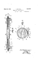
- - Fig. 3 isan enlarged vertical longitudinal section throughthe dope bar itself.
- a forced feed tubular dope bar A comprises two nesting tubes, an inner tube 1 and an outer tube 2.
- This description as to the c lindrical character of these surfaces only 1s made deliberately because of the fact that essentiall the inner surface 5 of the inner tube 1 an the outer surface 6 of the outer tube 2 need not be cylindrical.
- the inner surface of the inner tube may accommodate reinforcements, ribs and the like; whereas, the outer surface 6 of the outer tube may likewise accommodate re-inforcements inthe form of ribs or any other usual configurations for re-inforcements, against expansion.
- the mating circumscribed and inscribed surfaces 3 and 4 form a bearin and are capable of relative rotation, althoug it is to be understood that even this surface need not of necessity contact mutually throughout their entire extent, either circumferentially or longitudinally.
- Each tube, inner and outer, is provided with a lengthwise positioned slot or orifice preferably of considerable circumferential extent. These slots are indicated by 7 for the'inner tube and 8 for the outer tube.
- the limiting edge walls on one side of each of these slots are preferably straight and elemental, that is, corresponding with an element of the cylindrical surface.
- the edge 9 of the slot 7 is straight and elemental and likewise the ed 10 of the slot 8 is straight and elerhenta
- the walls of the tubes coral a 5 b knife edges the better to limit and define responding in localityto these be bevelled es, t at is along the edge the bevel 11 is provided, which is an internal bevel, and the edge an external bevel 12 is pro-, so that the actual orifice a is bounded operated rings 1 and 18 may be fixed to the .inner tube 1 rotatabl to adjust it in the brackets and 16. e actual adjustment can be indicated by the double scales 19 and 20 formed part on the brackets and part on the sleeves.
- Similar lever-operated sleeves 21 and 22 may be fixed to the ends of the outer tube for rotatably adjusting it relatively to the irmer tube, the position of adjustment being readily indicated by double scales such as 23 and 24, formed part on the sleeves 17 and. 18. Although these adjusting sleeves are shown necessitating the brackets 15 and 16, it is notconsidered that this is essential. There is nothing inherent in the design which I prevents the application of the brackets inwardly relative y to the inner sleeves 21' and 22.
- Means for closing the ends of the tube are shown in the form of caps 25 and 26 threaded on to the projecting ends of the inner tube.
- Dope supply ducts 27 and 28 are preferably mounted concentricall of the dope bar and are threaded throng out their entire extent and pass through internally threaded nip les 29 and 30 so that their discharge mout s 31 and 32 may be adjusted relatively to the dope bar b turning them relatively to the dope bar.
- e adjustment may be fixed by'the jamb nuts 33 and 34.
- the preferred adjustment for the dope supglsyt mouths 31 and 32 is one-fourth of the ance inwardly from the outer ends 35 and 36 of theextruding orifice a.
- tubes 1 and 2 may be roof d usually desirable tends to solidify if i3 1:
- This vat B may be of any suitable con struction but it is preferred. that it contain a mechanical mix-up 46.
- the force pump 0 taking its supply of dope from the vat B forces the dope thro h the supply duct 47, thence through to the dope resistant branches 49 and 50 to the end positioned dope supply ducts 27 and 28 previously described.
- a ressure gauge 51 may be employed as an in 'cator for t e working pressure.
- the fabric u n which the extruded sheet of dope is to applied as illustrated in the dra is shown as a woven textile fabric, it isto understood that this invention is more particularl adapted for the application of a sheet of ope to a more fr e fabric, which perforce, may be car rie on a carrier, although it is likewise useful in applying the dope to a woven textile fabric suc as that illustrated.
- inventive thought may have a variety of expressions as is contemplated in what we claim and desire to secure by United States Letters Patent as follows:
- a hollow forcedfeed do bar comprising two modulated c lindri shells ada ted to nest one within ti e other, and provi the width cooperative straight edges to form an extrusion slot; means for relatively rotating said shells; and means for rotating said shells as an entirety.
- a forced feed tubular dope bar comprising a tube provided with a lengthwise extended extrusion slot means for closing the ends of the tube; and a pair of dope sup ply ducts, the mouths of which disgorge into the interior of said tube at localities approximating one-fourth of the distance in from each extremity of said slot; and exit ducts opening outwardly from approximately the ends of said hollow dope bar.
- a forced feed tubular dope bar comprising two long nesting tubes, the nesting surfaces of which are cylindrical and each of which is provided with a longitudinal slot, one of the edges of which is elemental; separate means at each end of said dope bar for rotatin said tubes relatively to each other to regu ate the width of the orifice between said elemental edges, and independent means at each end of said dope bar for measuring the relative rotation at each end between the corresponding ends of said nesting tubes; and means for relatively fixing the ends of said two nesting tubes against relative rotation.
- a forced feedtubular dope bar having a longitudinally extensive laterally ositioned slot; means for closing the end 0 said bar; and threaded supply tubes having ad.
- a hollow forced feed dope bar for delivering a sheet of dope having in combination a rotary adjustment for adjusting the width of an extrusion slot and in addition, a rotary adjustment for adjusting the position of the extrusion slot, both said rotary adjustments being independent one of the other and both being about the same horizontal axis; and
Description
March 29, L DAY ET AL FORCED FEED TUBULAR DOPE BAR Filed April 3, 1924 2 Sheets-Sheet 1 a wozo Zeorzard firg March 29, 1932. 1 DAY ET AL FORCED FEED TUBULAR DOPE BAR 2 Sheets-Sheet Filed April 3, 1924 Emil l lmiev'm/ INVENTORS Zahara flay AT RNEY .E.. i in directly Patented Mar. 1932 UNITED STATES PATENT OFFICE LEONARD DAY 1 111) mm. 01m YORK, H. Y., ABSIGN'OBS' TO m I ",DI'NEWYOBLN-Y.
FORCED I'EED TUBULAR DOPE Application am A ril a, 1924. Serial No. 704,074.
This invention relates to apparatus useful in the production of substitute leather. In'the majority of cases, substitute leathers heretofore have started with a body fabric which, itself, ,has suflicient tensile strength to withstand the application of dope by means of a scraping dope bar. In some instances, an attempt to apply the do e in a spray has been made; but
this, necessity, limits the dope to be employed to one containing a large amount of volatile solvent, which must be evaporated out of the body fabric causing blisters and generally bein unsatisfactory for any purpose. Obvio real leather does not comrise a textile abric body, but consists'of'a ody of matted fibres;
The present invention is directed to an apparatus particularly adapted for use in the practice of the newer process for making substitute leather invented by Emil Weinheim. This process employs a body fabric which may be without initial tensile strength suflicient to withstand the scraping actlon of the ordinary dope bar. The Weinheim process contemplates the extrusion or feeding by any means of a sheet of viscous dogs u on a travelling body fabric, t 'e feedin of the dope sheet being at the same rate 0 speed as the travel of the body fabric, so that there shall be no disturbance of the friable fragile substance composing the body fabric.
It is,.therefore, an object ofthis invention to provide a forced feed dope bar of such a character that a sheet of viscous dope of uniform thickness may be'extrudedv with con-' venience and dis etch and such that the dope bar itself may adjusted in position and may be mounted readily above and transversely to a travellin strip of body fabric.
Further objects of the invention are to rovide for the introduction and control 0 the supply of the dope and for the relief of the dope bar against excessive pressures, and also to conserve the dope employed.
This and further objects of the invention will better be understood by reference to the illustrative embodiment thereof, to which the claims are directed solely for purposes of plete machine embodying the dope bar, and
- Fig. 3 isan enlarged vertical longitudinal section throughthe dope bar itself.
A forced feed tubular dope bar A. comprises two nesting tubes, an inner tube 1 and an outer tube 2. The outer surface 3 of the inner tube 1, which contacts with'the inner surface 4 of the outer tube 2, being cylindrical as is the surface 4 of the outer tube, the one being circumscribed within the other. This description as to the c lindrical character of these surfaces only 1s made deliberately because of the fact that essentiall the inner surface 5 of the inner tube 1 an the outer surface 6 of the outer tube 2 need not be cylindrical. For example, the inner surface of the inner tube may accommodate reinforcements, ribs and the like; whereas, the outer surface 6 of the outer tube may likewise accommodate re-inforcements inthe form of ribs or any other usual configurations for re-inforcements, against expansion. The mating circumscribed and inscribed surfaces 3 and 4, however, as it were, form a bearin and are capable of relative rotation, althoug it is to be understood that even this surface need not of necessity contact mutually throughout their entire extent, either circumferentially or longitudinally.
Each tube, inner and outer, is provided witha lengthwise positioned slot or orifice preferably of considerable circumferential extent. These slots are indicated by 7 for the'inner tube and 8 for the outer tube. The limiting edge walls on one side of each of these slots are preferably straight and elemental, that is, corresponding with an element of the cylindrical surface. For example, the edge 9 of the slot 7 is straight and elemental and likewise the ed 10 of the slot 8 is straight and elerhenta It is preferred also that the walls of the tubes coral a 5 b knife edges, the better to limit and define responding in localityto these be bevelled es, t at is along the edge the bevel 11 is provided, which is an internal bevel, and the edge an external bevel 12 is pro-, so that the actual orifice a is bounded operated rings 1 and 18 may be fixed to the .inner tube 1 rotatabl to adjust it in the brackets and 16. e actual adjustment can be indicated by the double scales 19 and 20 formed part on the brackets and part on the sleeves. Similar lever-operated sleeves 21 and 22 may be fixed to the ends of the outer tube for rotatably adjusting it relatively to the irmer tube, the position of adjustment being readily indicated by double scales such as 23 and 24, formed part on the sleeves 17 and. 18. Although these adjusting sleeves are shown necessitating the brackets 15 and 16, it is notconsidered that this is essential. There is nothing inherent in the design which I prevents the application of the brackets inwardly relative y to the inner sleeves 21' and 22.
Means for closing the ends of the tube are shown in the form of caps 25 and 26 threaded on to the projecting ends of the inner tube. Dope supply ducts 27 and 28 are preferably mounted concentricall of the dope bar and are threaded throng out their entire extent and pass through internally threaded nip les 29 and 30 so that their discharge mout s 31 and 32 may be adjusted relatively to the dope bar b turning them relatively to the dope bar. e adjustment may be fixed by'the jamb nuts 33 and 34. The preferred adjustment for the dope supglsyt mouths 31 and 32 is one-fourth of the ance inwardly from the outer ends 35 and 36 of theextruding orifice a. This tends to insure the most'nearly uniform presure possible for efiectin the extrusion of the sheet 13 of dope, which should be extruded so that when it lies horizontally as a layer 37 upon the carrier 38, it can travel in the direction of the arrow at the same speed as the underlying carrier fabric 38 without ap lying any forward dragging or retarding e ect at the extrusion orifice that is, without tend- 7 ing to change the configuration of the bend 13. This necessitates the same extrusion speed at the orifice a as is the travel of the fabric 38.
Obviously the tubes 1 and 2 may be roof d usually desirable tends to solidify if i3 1:
allowedtocoolofiaswouldbethecase' u ,n intheexpM do barwith- 01 1? arenewal of the sup 1y. 'To irovide for this circulation, return ucts 41 and 42 are tapped intoth'e ,ends of the bar or otherwise I6 the same length and. preferablyof the same type of tEiping so-that the flow out of each end of e dope bar willbe uniform. relief valve 45 is adjusted preferably to maintain the same internal the bar A when the orifice is closed of 'as would be the case when the orifice was open and-working, the different function that the outward flow of dope is backed into the vat B. v
This vat B may be of any suitable con struction but it is preferred. that it contain a mechanical mix-up 46. The force pump 0 taking its supply of dope from the vat B forces the dope thro h the supply duct 47, thence through to the dope resistant branches 49 and 50 to the end positioned dope supply ducts 27 and 28 previously described. A ressure gauge 51 may be employed as an in 'cator for t e working pressure.
Note'the disclosure in theeap lication of Emil Weinheim for forced f Ser. No. 702,472, filed March 26, 1924.
Although the fabric u n which the extruded sheet of dope is to applied as illustrated in the dra is shown as a woven textile fabric, it isto understood that this invention is more particularl adapted for the application of a sheet of ope to a more fr e fabric, which perforce, may be car rie on a carrier, although it is likewise useful in applying the dope to a woven textile fabric suc as that illustrated.
The inventive thought may have a variety of expressions as is contemplated in what we claim and desire to secure by United States Letters Patent as follows:
1. A hollow forced feed dope bar for delivering a sheet of dope having in combinadope bar,
tion two parts relatively rotatable about the same axis to provide an extrusion slot and a rotary adjustment for adjusting of said extrusion slot and means providing a rotary adjustment foradjgsting the position of the extrusionslot th saidrotary adjustments being about the same 2. A hollow forcedfeed do bar comprising two modulated c lindri shells ada ted to nest one within ti e other, and provi the width cooperative straight edges to form an extrusion slot; means for relatively rotating said shells; and means for rotating said shells as an entirety.
3. A forced feed tubular dope bar comprising a tube provided with a lengthwise extended extrusion slot means for closing the ends of the tube; and a pair of dope sup ply ducts, the mouths of which disgorge into the interior of said tube at localities approximating one-fourth of the distance in from each extremity of said slot; and exit ducts opening outwardly from approximately the ends of said hollow dope bar. I
4. A forced feed tubular dope bar comprising two long nesting tubes, the nesting surfaces of which are cylindrical and each of which is provided with a longitudinal slot, one of the edges of which is elemental; separate means at each end of said dope bar for rotatin said tubes relatively to each other to regu ate the width of the orifice between said elemental edges, and independent means at each end of said dope bar for measuring the relative rotation at each end between the corresponding ends of said nesting tubes; and means for relatively fixing the ends of said two nesting tubes against relative rotation.
5. A forced feedtubular dope bar having a longitudinally extensive laterally ositioned slot; means for closing the end 0 said bar; and threaded supply tubes having ad.-
.justable threaded engagement through the end closin means of said bar whereby a relative rotation between said supply tubes and said bar will effect an adjustment in position for the discharge mouth of said tubesu relatively to said bar.
6. A hollow forced feed dope bar for delivering a sheet of dope, having in combination a rotary adjustment for adjusting the width of an extrusion slot and in addition, a rotary adjustment for adjusting the position of the extrusion slot, both said rotary adjustments being independent one of the other and both being about the same horizontal axis; and
means for fixing the rotary adjustment of said dope bar as a whole.
In witness whereof, we have signed our names to this specification, this 10th day of November, 1923.
LEONARD DAY.
EMIL WEINHEIM.
Priority Applications (1)
| Application Number | Priority Date | Filing Date | Title |
|---|---|---|---|
| US704074A US1851538A (en) | 1924-04-03 | 1924-04-03 | Forced feed tubular dope bar |
Applications Claiming Priority (1)
| Application Number | Priority Date | Filing Date | Title |
|---|---|---|---|
| US704074A US1851538A (en) | 1924-04-03 | 1924-04-03 | Forced feed tubular dope bar |
Publications (1)
| Publication Number | Publication Date |
|---|---|
| US1851538A true US1851538A (en) | 1932-03-29 |
Family
ID=24827957
Family Applications (1)
| Application Number | Title | Priority Date | Filing Date |
|---|---|---|---|
| US704074A Expired - Lifetime US1851538A (en) | 1924-04-03 | 1924-04-03 | Forced feed tubular dope bar |
Country Status (1)
| Country | Link |
|---|---|
| US (1) | US1851538A (en) |
Cited By (16)
| Publication number | Priority date | Publication date | Assignee | Title |
|---|---|---|---|---|
| US2431029A (en) * | 1945-03-29 | 1947-11-18 | David H Duffy | Machine for icing cake or the like |
| US2464771A (en) * | 1946-04-09 | 1949-03-15 | Interstate Folding Box Co | Apparatus for coating webs |
| US2472199A (en) * | 1945-12-08 | 1949-06-07 | E D Etnyre & Co | Distributor for bitumen and like material |
| US2577886A (en) * | 1947-09-27 | 1951-12-11 | Block & Anderson Ltd | Moistener for hectograph duplicators |
| US2731944A (en) * | 1956-01-24 | Housing for removable attachment | ||
| US2778991A (en) * | 1951-06-27 | 1957-01-22 | Belden Mfg Co | Splice detection procedures and apparatus |
| US2784697A (en) * | 1952-12-16 | 1957-03-12 | Enamelstrip Corp | Apparatus for coating metallic strips |
| US2788051A (en) * | 1953-01-02 | 1957-04-09 | Honeycomb Structures Company I | Apparatus for applying a coating to sheet material |
| US2897777A (en) * | 1956-01-26 | 1959-08-04 | Olin Mathieson | Impregnating device and process |
| US3191996A (en) * | 1962-11-16 | 1965-06-29 | American Tech Mach Co | Twisting mechanism |
| US3234041A (en) * | 1960-01-29 | 1966-02-08 | Owens Corning Fiberglass Corp | Method of applying binder to porous fibrous glass mats |
| US3319603A (en) * | 1962-10-26 | 1967-05-16 | Hesselmann Willy | Apparatus for the application of liquid substances, particularly adhesives |
| US3408981A (en) * | 1963-11-07 | 1968-11-05 | Robert B. Poppe | Extruder head useful in pastrymaking apparatus |
| US3460513A (en) * | 1965-08-24 | 1969-08-12 | Wilhelm Hesselmann | Dispenser for coating a moving sheet |
| US3712264A (en) * | 1970-09-16 | 1973-01-23 | Lehara W Inc | Rotating paste depositer |
| US4534309A (en) * | 1983-11-17 | 1985-08-13 | Consolidated Papers, Inc. | Paper coating apparatus |
-
1924
- 1924-04-03 US US704074A patent/US1851538A/en not_active Expired - Lifetime
Cited By (16)
| Publication number | Priority date | Publication date | Assignee | Title |
|---|---|---|---|---|
| US2731944A (en) * | 1956-01-24 | Housing for removable attachment | ||
| US2431029A (en) * | 1945-03-29 | 1947-11-18 | David H Duffy | Machine for icing cake or the like |
| US2472199A (en) * | 1945-12-08 | 1949-06-07 | E D Etnyre & Co | Distributor for bitumen and like material |
| US2464771A (en) * | 1946-04-09 | 1949-03-15 | Interstate Folding Box Co | Apparatus for coating webs |
| US2577886A (en) * | 1947-09-27 | 1951-12-11 | Block & Anderson Ltd | Moistener for hectograph duplicators |
| US2778991A (en) * | 1951-06-27 | 1957-01-22 | Belden Mfg Co | Splice detection procedures and apparatus |
| US2784697A (en) * | 1952-12-16 | 1957-03-12 | Enamelstrip Corp | Apparatus for coating metallic strips |
| US2788051A (en) * | 1953-01-02 | 1957-04-09 | Honeycomb Structures Company I | Apparatus for applying a coating to sheet material |
| US2897777A (en) * | 1956-01-26 | 1959-08-04 | Olin Mathieson | Impregnating device and process |
| US3234041A (en) * | 1960-01-29 | 1966-02-08 | Owens Corning Fiberglass Corp | Method of applying binder to porous fibrous glass mats |
| US3319603A (en) * | 1962-10-26 | 1967-05-16 | Hesselmann Willy | Apparatus for the application of liquid substances, particularly adhesives |
| US3191996A (en) * | 1962-11-16 | 1965-06-29 | American Tech Mach Co | Twisting mechanism |
| US3408981A (en) * | 1963-11-07 | 1968-11-05 | Robert B. Poppe | Extruder head useful in pastrymaking apparatus |
| US3460513A (en) * | 1965-08-24 | 1969-08-12 | Wilhelm Hesselmann | Dispenser for coating a moving sheet |
| US3712264A (en) * | 1970-09-16 | 1973-01-23 | Lehara W Inc | Rotating paste depositer |
| US4534309A (en) * | 1983-11-17 | 1985-08-13 | Consolidated Papers, Inc. | Paper coating apparatus |
Similar Documents
| Publication | Publication Date | Title |
|---|---|---|
| US1851538A (en) | Forced feed tubular dope bar | |
| US2893315A (en) | Means for producing a textile fabric having exceptional wear resistance | |
| US2796846A (en) | Means for applying fluent coatings to web material at open width | |
| US3096772A (en) | Device for providing cigarettes with an axial air duct | |
| US772695A (en) | Drier for paper, cloth, &c. | |
| US2653566A (en) | Web coating machine | |
| DE2340177A1 (en) | DEVICE FOR COVERING TRACKS | |
| DE1237052B (en) | Drum dryer | |
| US2314453A (en) | Coating and filming machine and apparatus | |
| DE836793C (en) | Machine for printing textile fabrics | |
| US2249507A (en) | Film or sheet forming apparatus | |
| DE555366C (en) | Device for introducing grainy or fibrous conveyed material into compressed air lines | |
| US1141320A (en) | Manufacture of printers' rollers. | |
| US1680711A (en) | Art of striping paper | |
| DE1265565B (en) | Device for coating paper, cardboard or the like. | |
| US2331207A (en) | Apparatus for the liquid treatment of yarn and the like | |
| US1119820A (en) | Coating-machine. | |
| US2025375A (en) | Method of coating webs | |
| US1911001A (en) | Creping machine | |
| US95689A (en) | Improved machine for tarring- paper for roofing | |
| DE953767C (en) | Cylindrical sieve dewatering machine working with negative pressure | |
| US1535447A (en) | Machine for forming artificial leather or the like | |
| DE393557C (en) | Device for feeding fine material into the melting zone of the blast furnace | |
| DE472608C (en) | Around a vertical axis revolving, provided with a cavity for receiving the ink supply inking roller for stamping machines u. like | |
| US923870A (en) | Paper-machine. |