US1851948A - Gasket - Google Patents
Gasket Download PDFInfo
- Publication number
- US1851948A US1851948A US179964A US17996427A US1851948A US 1851948 A US1851948 A US 1851948A US 179964 A US179964 A US 179964A US 17996427 A US17996427 A US 17996427A US 1851948 A US1851948 A US 1851948A
- Authority
- US
- United States
- Prior art keywords
- gasket
- layer
- layers
- joint
- corrugations
- Prior art date
- Legal status (The legal status is an assumption and is not a legal conclusion. Google has not performed a legal analysis and makes no representation as to the accuracy of the status listed.)
- Expired - Lifetime
Links
- 238000007789 sealing Methods 0.000 description 15
- 239000000463 material Substances 0.000 description 5
- 239000002184 metal Substances 0.000 description 4
- 239000002131 composite material Substances 0.000 description 3
- 238000005304 joining Methods 0.000 description 3
- 238000005452 bending Methods 0.000 description 2
- 238000005266 casting Methods 0.000 description 2
- 238000001816 cooling Methods 0.000 description 2
- 239000013013 elastic material Substances 0.000 description 2
- 239000012530 fluid Substances 0.000 description 2
- 238000010438 heat treatment Methods 0.000 description 2
- 229910001369 Brass Inorganic materials 0.000 description 1
- 229910000906 Bronze Inorganic materials 0.000 description 1
- OAICVXFJPJFONN-UHFFFAOYSA-N Phosphorus Chemical compound [P] OAICVXFJPJFONN-UHFFFAOYSA-N 0.000 description 1
- 229910000639 Spring steel Inorganic materials 0.000 description 1
- 229910000831 Steel Inorganic materials 0.000 description 1
- 229910045601 alloy Inorganic materials 0.000 description 1
- 239000000956 alloy Substances 0.000 description 1
- 239000010951 brass Substances 0.000 description 1
- 239000010974 bronze Substances 0.000 description 1
- KUNSUQLRTQLHQQ-UHFFFAOYSA-N copper tin Chemical compound [Cu].[Sn] KUNSUQLRTQLHQQ-UHFFFAOYSA-N 0.000 description 1
- 238000005242 forging Methods 0.000 description 1
- 238000004519 manufacturing process Methods 0.000 description 1
- 238000003825 pressing Methods 0.000 description 1
- 239000010959 steel Substances 0.000 description 1
Images

Classifications
-
- F—MECHANICAL ENGINEERING; LIGHTING; HEATING; WEAPONS; BLASTING
- F16—ENGINEERING ELEMENTS AND UNITS; GENERAL MEASURES FOR PRODUCING AND MAINTAINING EFFECTIVE FUNCTIONING OF MACHINES OR INSTALLATIONS; THERMAL INSULATION IN GENERAL
- F16J—PISTONS; CYLINDERS; SEALINGS
- F16J15/00—Sealings
- F16J15/02—Sealings between relatively-stationary surfaces
- F16J15/06—Sealings between relatively-stationary surfaces with solid packing compressed between sealing surfaces
- F16J15/10—Sealings between relatively-stationary surfaces with solid packing compressed between sealing surfaces with non-metallic packing
- F16J15/12—Sealings between relatively-stationary surfaces with solid packing compressed between sealing surfaces with non-metallic packing with metal reinforcement or covering
- F16J15/121—Sealings between relatively-stationary surfaces with solid packing compressed between sealing surfaces with non-metallic packing with metal reinforcement or covering with metal reinforcement
- F16J15/122—Sealings between relatively-stationary surfaces with solid packing compressed between sealing surfaces with non-metallic packing with metal reinforcement or covering with metal reinforcement generally parallel to the surfaces
Definitions
- This invention relates to devices for sealing joints between surfaces particularly to gaskets for making a fluid-tight joint between conduits or other hollow bodies.
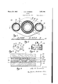
- Fig. l is a plan of one of the members of a composite gasket embodying my invention.
- Fig. 2 is a section on the line 22 of Figure 1.
- Fig. 3 is a plan on a reduced scale of an asmicd gasket.
- Fig. 4 is an elevation of a joint including my improved gasket.
- Figs. 5, 6, 7 and 8 are fragmentary sectional views of the assembled joint, corresponding to the section 011 line 5-5 of Fig. 3 and drawn on a greatly enlarged scale, showing the gasket under a variety of conditions, and
- Fig. 9 is a-plan view corresponding to Fig. 1 of one of the members of a modified form of gasket.
- Figs. f and 5 illustrate the invention as embodied in a oint between a flanged conduit connection 20 and a casting 21, such as a cylinder head of a compressor.
- the bodies to be joined have generally flat opposed surfaces 22 and 23 and are held to gether by bolts or the like 24.
- the opposed surfaces need not be perfectly smooth, but as indicated in Figs. 5 to 8, may be what would be considered in this art as quite rough, for example the surfaces of forgings or of roughly machined castings.
- Adjacent each surface I place a layer 25 or 26 of relatively soft or plastic material, for example lead, or a soft alloy, and between the soft layers I place a layer 27 of elastic material, for example spring steel, phosphor bronze or the like. All of the layers are of the same general contour as the surfaces to be joined, as shown in Figs. 1 and 3.
- Each layer has a principal opening 28 which registers with the conduit openings 29 in the members to be joined, and in the embodiment illustrated in Figs. 1 to 4, has a pair of additional principal openings 30 for the bolts.
- Each layer also has one or more secondary openings 31.
- the layers are symmetrical with reference to their principal openings and asymmetrical with reference to the secondary openings. The purpose of this arrangement is to facilitate assemblage and securing together of composite gasket using two identical plastic layers, which can be stamped by the same tool.
- Fig. 3 shows the layers so assembled, the openings 31 shown in solid lines being those of layers 25 and 27 while the openings 31 shown in dotted lines are those of layer 26.
- the layer 26 is punched thru the openings 31 in the layers 25 and 27, and may be riveted or crimped as shown at 32, to hold the gasket together.
- the crimped portion 32 does not interfere with the sealing or with clamping together the members to be joined, due to flow and/or bending of the crimped portion and/or the surrounding area of the sheet 25, upon being put under pressure, there being sufficient space between layers 25 and 26 wlthm the height of the corrugations 40 of the elastic layer to permit suchflow or bending.
- a gasket composed of a layer of plastic material may not be satisfactory when used With devices which are subject to considerable variation in temperature.
- My invention overcomes the difficulties above described and maintains a tight seal under widely varying conditions of the joint.
- the elastlc layer is designed to form an elastic member between the plastic layers which always holds the plastic layers in sealing engagement with the surfaces 22 and 23 and also maintains sealing contact with the plastic layers themselves.
- the elastic layer is provided with one or more corrugations 4O surrounding the opening to be sealed, and if desired, there may be additional corrugations 41 around the bolt holes.
- Fig. 5 represents the joint assembled but before the bolts have been tightened. 'The plastic layers are lightly in contact with the elastic layer, but may be out of contactwith either or both of the surfaces 22 and 23, which are a distance D5 apart.
- Fig. 6 represents the joint after the bolts have been tightened to hold a given pressure, for example when the joint is cold.
- the surfaces are now adistance D6 apart, which is obviously. less than D5, and the pressure of the bolts urging the surfaces toward one another has flattened the corrugations somewhat, deforming the plastic layers to conform to the corrugations, and pressing them firmly into the irregularities of the surfaces 22 and 23 at the points opposite the corrugations.
- the plastic layer has been compressed to a thickness T6 opposite the points 33 of the corrugations, and the gasket 26 has been upset to a thickness t6 between the heels 34 of the corrugations.
- Fig. 7 the joint is represented with the surfaces closer together than in Fig. 6, which condition may be effected, for example, by heating the joint, or by tightening the bolts.
- the surfaces are now a distance apart D7 which is less than D6, the corrugations have been flattened still more, and the plastic layers may be in sealing contact with the surface and the elastic layer at all points.
- Both the thickness T7 of the layer 25 above the points of the corrugations, and the thickness t7 of the layer 26 between the heels of the corrugations may now be less than T6 and t6 respectively.
- Fig. 8 the joint has loosened, for instance by cooling, or loosening of the bolts, so that the surfaces are again a distance apart D6.
- the elastic corrugations tend to assume their original shape as shown in Fig. 5, the points 33 following the layer 25 and the heels 34 following the layer 26.
- the corrugations take up the space left by the shrinking of the joint and urge these layers apart, maintaining them in sealing contact with the surfaces 22 and 23, and maintaining sealing contact between the elastic layer and the plastic layers.
- Each corrugation thus provides a continuous member surrounding the opening, always in sealing contact with both plastic layers, and always urging the plastic layers into sealing contact with the surfaces to be joined.
- the articular form of gasket in Fig. 3 is especially adapted to join sections of conduits in which the principal opening 28 forms the passage for fluid.
- My invention is equally suitable to joining together any hollow bodies, such as cylinders and crankcases of engines and compressors.
- a form of gasket suitable for joining the cylinder to the crankcase'of a compressor is shown in Fig; 9.
- This figure re resents a plan view of the elastic member 0 such a gasket;
- the gasket 38 having a principal opening 39 has a plurality of bolt holes 42 each of which is surrounded by a corrugation 43. If desired, other corrugations 44 and 45 may be used to surround the entire group of bolt holes, thus providing additional protection against leakage.
- Means for sealing a joint between two surfaces comprising in combination a flat independent ply of plastic material in contact with one surface, and sheet metal spring means between said ply and the other surface, said. sheet metal spring means having an annular corrugation, said corrugation being adapted to flex in one direction when the surfaces are moved together and to flex in the opposite direction and maintain sealing contact with the plastic ply when the surfaces are thereafter separated.
- Means for sealing a joint between two m surfaces comprising in combination a pair of flat independent plies of a plastic material, one of said plies being in contact with one of said surfaces and the other of said plies being in contact with the other of said 15 surfaces, and sheet metal spring means between said plies, said sheet metal spring means having an annular corrugation therein, said corrugation being adapted to flex in one direction when said surfaces are moved 20 together and to maintain sealing contact with the plastic ply when the surfaces are thereafter separated.
- Means for sealing a joint between two surfaces comprising in combination, a layer ofplastic material in contact with each surface, and a layer of elastic material between the plastic layers, the elastic layer and one of the plastic layers having aligned openings, and the other plastic layer being deformed to 2m project through said openings and hold all of the layers together.
- Acomposite gasket comprising a pair of relatively soft plane layers and a relatively hard corrugated layer between the soft layers, one of the soft layers having a portion bent over the other soft layer to old all of the layers together, the height of the corrugation being equal to or greater than the thickness of said bent-over portion to pro- 40 vide space for receiving the bent-over portion within the normal thickness of the gasket.
Description
March 29, 1932. 0, SUMMERS 1,851,948
GASKET Filed March 31, 1927 2 Sheets-Sheet l lllll mm &\\\\\\\\\\\ Y2 T W/ A 4 I x\ & Y 26 Patented Mar. 29, 1932 UNITED STATES PATENT OFFICE OTTO M. SUMMERS, OF DAYTON, OHIO, ASSIGNOR, BY MESNE ASSIGNMENTS, TO FRIGID- AIR-E CORPORATION, A CORPORATION OF DELAWARE GASKET Application filed March 31, 1927. Serial No. 179,964.
This invention relates to devices for sealing joints between surfaces particularly to gaskets for making a fluid-tight joint between conduits or other hollow bodies.
It is among the objects of the invention to provide a gasket having improved sealing properties, particularly at high pressures, to provide means for readily joining bodies or surfaces which are comparatively rough, and to provide a seal which is effective to maintain a pressure-tight joint, even when subjected to considerable variation in temperature. It is also among the objects of the invention to provide a composite gasket which is easily fabricated, one in which the component parts are effectively held together to withstand handling and transportation and one which requires a minimum of tools for its manufacture.
Further objects and advantages of the present invention will be apparent from the following description, reference being had to the accompanying drawings, wherein a preferred form of the present invention is clearly shown.
In the drawings:
Fig. l is a plan of one of the members of a composite gasket embodying my invention.
Fig. 2 is a section on the line 22 of Figure 1.
Fig. 3 is a plan on a reduced scale of an as sembled gasket.
Fig. 4 is an elevation of a joint including my improved gasket.
Figs. 5, 6, 7 and 8 are fragmentary sectional views of the assembled joint, corresponding to the section 011 line 5-5 of Fig. 3 and drawn on a greatly enlarged scale, showing the gasket under a variety of conditions, and
Fig. 9 is a-plan view corresponding to Fig. 1 of one of the members of a modified form of gasket.
In the drawings, Figs. f and 5 illustrate the invention as embodied in a oint between a flanged conduit connection 20 and a casting 21, such as a cylinder head of a compressor. The bodies to be joined have generally flat opposed surfaces 22 and 23 and are held to gether by bolts or the like 24. The opposed surfaces need not be perfectly smooth, but as indicated in Figs. 5 to 8, may be what would be considered in this art as quite rough, for example the surfaces of forgings or of roughly machined castings. Adjacent each surface I place a layer 25 or 26 of relatively soft or plastic material, for example lead, or a soft alloy, and between the soft layers I place a layer 27 of elastic material, for example spring steel, phosphor bronze or the like. All of the layers are of the same general contour as the surfaces to be joined, as shown in Figs. 1 and 3.
Each layer has a principal opening 28 which registers with the conduit openings 29 in the members to be joined, and in the embodiment illustrated in Figs. 1 to 4, has a pair of additional principal openings 30 for the bolts. Each layer also has one or more secondary openings 31. The layers are symmetrical with reference to their principal openings and asymmetrical with reference to the secondary openings. The purpose of this arrangement is to facilitate assemblage and securing together of composite gasket using two identical plastic layers, which can be stamped by the same tool. In assembling the gasket, the elastic layer 27 and one plastic layer 25 are placed with their secondary openings in alignment, but the other plastic layer 26 is reversed with respect to these layers, so as to bring its secondary openings out of alignment and to present an imperforate surface opposite the secondary openings of the other layers. Fig. 3 shows the layers so assembled, the openings 31 shown in solid lines being those of layers 25 and 27 while the openings 31 shown in dotted lines are those of layer 26. After beingso assembled, the layer 26 is punched thru the openings 31 in the layers 25 and 27, and may be riveted or crimped as shown at 32, to hold the gasket together. The crimped portion 32 does not interfere with the sealing or with clamping together the members to be joined, due to flow and/or bending of the crimped portion and/or the surrounding area of the sheet 25, upon being put under pressure, there being sufficient space between layers 25 and 26 wlthm the height of the corrugations 40 of the elastic layer to permit suchflow or bending.
In previous attempts to seal members by means of clamping a soft gasket between them it has been found that when the joint is tightened the surfaces are forced together and may squeeze out the soft gasket layer, making it appreciably thinner than it was before. If the joint thereafter becomes loose, the surfaces recede from each other and the gasket being thinner than it was before, it will not occupy all of the space between the members but will permit fluid to leak thru the joint. The condition above described may be produced by exposing the joint to a varying temperature, particularly if-the joint includes one or more brass members held together by steel bolts, in which case the expansion of the joint on being heated will force the surfaces toward each other and the subsequent shrinking of the joint on being cooled will allow the surfaces to recede from each other. Therefore, a gasket composed of a layer of plastic material may not be satisfactory when used With devices which are subject to considerable variation in temperature. My invention overcomes the difficulties above described and maintains a tight seal under widely varying conditions of the joint. The elastlc layer is designed to form an elastic member between the plastic layers which always holds the plastic layers in sealing engagement with the surfaces 22 and 23 and also maintains sealing contact with the plastic layers themselves. To this end the elastic layer is provided with one or more corrugations 4O surrounding the opening to be sealed, and if desired, there may be additional corrugations 41 around the bolt holes. Fig. 5 represents the joint assembled but before the bolts have been tightened. 'The plastic layers are lightly in contact with the elastic layer, but may be out of contactwith either or both of the surfaces 22 and 23, which are a distance D5 apart.
Fig. 6 represents the joint after the bolts have been tightened to hold a given pressure, for example when the joint is cold. The surfaces are now adistance D6 apart, which is obviously. less than D5, and the pressure of the bolts urging the surfaces toward one another has flattened the corrugations somewhat, deforming the plastic layers to conform to the corrugations, and pressing them firmly into the irregularities of the surfaces 22 and 23 at the points opposite the corrugations. Likewise the plastic layer has been compressed to a thickness T6 opposite the points 33 of the corrugations, and the gasket 26 has been upset to a thickness t6 between the heels 34 of the corrugations. Thus a tight seal is established between surfaces 22 and 23 in the region of the corrugations.
In Fig. 7 the joint is represented with the surfaces closer together than in Fig. 6, which condition may be effected, for example, by heating the joint, or by tightening the bolts. The surfaces are now a distance apart D7 which is less than D6, the corrugations have been flattened still more, and the plastic layers may be in sealing contact with the surface and the elastic layer at all points. Both the thickness T7 of the layer 25 above the points of the corrugations, and the thickness t7 of the layer 26 between the heels of the corrugations may now be less than T6 and t6 respectively.
In Fig. 8 the joint has loosened, for instance by cooling, or loosening of the bolts, so that the surfaces are again a distance apart D6. As the surfacesrecede from each other the elastic corrugations tend to assume their original shape as shown in Fig. 5, the points 33 following the layer 25 and the heels 34 following the layer 26. Thus, while the portions of the plastic layers adjacent the corrugations retain their reduced thicknesses T7 and t7, the corrugations take up the space left by the shrinking of the joint and urge these layers apart, maintaining them in sealing contact with the surfaces 22 and 23, and maintaining sealing contact between the elastic layer and the plastic layers. Each corrugation thus provides a continuous member surrounding the opening, always in sealing contact with both plastic layers, and always urging the plastic layers into sealing contact with the surfaces to be joined.
Upon subsequent heating and cooling, the plastic layers will retain the forms shown in Figs. 7 and 8 while the elastic layer will vary between the two forms shown.
The articular form of gasket in Fig. 3 is especially adapted to join sections of conduits in which the principal opening 28 forms the passage for fluid. My invention is equally suitable to joining together any hollow bodies, such as cylinders and crankcases of engines and compressors. A form of gasket suitable for joining the cylinder to the crankcase'of a compressor is shown in Fig; 9. This figure re resents a plan view of the elastic member 0 such a gasket; In this figure the gasket 38 having a principal opening 39 has a plurality of bolt holes 42 each of which is surrounded by a corrugation 43. If desired, other corrugations 44 and 45 may be used to surround the entire group of bolt holes, thus providing additional protection against leakage.
While the form of embodiment of the invention as herein disclosed, constitutes a preferred form, it is to be understood that other forms might be adopted, all coming within the scope of the claims which follow.
What is claimed is as follows:
1. Means for sealing a joint between two surfaces comprising in combination a flat independent ply of plastic material in contact with one surface, and sheet metal spring means between said ply and the other surface, said. sheet metal spring means having an annular corrugation, said corrugation being adapted to flex in one direction when the surfaces are moved together and to flex in the opposite direction and maintain sealing contact with the plastic ply when the surfaces are thereafter separated.
2. Means for sealing a joint between two m surfaces comprising in combination a pair of flat independent plies of a plastic material, one of said plies being in contact with one of said surfaces and the other of said plies being in contact with the other of said 15 surfaces, and sheet metal spring means between said plies, said sheet metal spring means having an annular corrugation therein, said corrugation being adapted to flex in one direction when said surfaces are moved 20 together and to maintain sealing contact with the plastic ply when the surfaces are thereafter separated. 3. Means for sealing a joint between two surfaces comprising in combination, a layer ofplastic material in contact with each surface, and a layer of elastic material between the plastic layers, the elastic layer and one of the plastic layers having aligned openings, and the other plastic layer being deformed to 2m project through said openings and hold all of the layers together. 4. Acomposite gasket comprising a pair of relatively soft plane layers and a relatively hard corrugated layer between the soft layers, one of the soft layers having a portion bent over the other soft layer to old all of the layers together, the height of the corrugation being equal to or greater than the thickness of said bent-over portion to pro- 40 vide space for receiving the bent-over portion within the normal thickness of the gasket.
In testimony whereof I hereto 'aflii my signature.
OTTO M. SUMMERS.
Priority Applications (1)
| Application Number | Priority Date | Filing Date | Title |
|---|---|---|---|
| US179964A US1851948A (en) | 1927-03-31 | 1927-03-31 | Gasket |
Applications Claiming Priority (1)
| Application Number | Priority Date | Filing Date | Title |
|---|---|---|---|
| US179964A US1851948A (en) | 1927-03-31 | 1927-03-31 | Gasket |
Publications (1)
| Publication Number | Publication Date |
|---|---|
| US1851948A true US1851948A (en) | 1932-03-29 |
Family
ID=22658722
Family Applications (1)
| Application Number | Title | Priority Date | Filing Date |
|---|---|---|---|
| US179964A Expired - Lifetime US1851948A (en) | 1927-03-31 | 1927-03-31 | Gasket |
Country Status (1)
| Country | Link |
|---|---|
| US (1) | US1851948A (en) |
Cited By (40)
| Publication number | Priority date | Publication date | Assignee | Title |
|---|---|---|---|---|
| US3391940A (en) * | 1966-01-10 | 1968-07-09 | Federal Mogul Corp | Wear sleeve having a gasketing flange and a tapered wall for spacing a cylindrical wear sleeve portion from a rotary member and engine installation incorporating said wear sleeve |
| US4088347A (en) * | 1974-11-27 | 1978-05-09 | Daimler-Benz Aktiengesellschaft | Sealing arrangement |
| US4196913A (en) * | 1976-07-14 | 1980-04-08 | Kosaku Ueda | Gaskets |
| FR2470903A1 (en) * | 1979-12-03 | 1981-06-12 | Nicholson Terence | CYLINDER HEAD GASKETS |
| DE3306759A1 (en) * | 1982-05-17 | 1983-11-17 | Nihon Metal Gasket Kabushiki Kaisha, Urawa, Saitama | METAL GASKET WASHER |
| US4721315A (en) * | 1985-12-27 | 1988-01-26 | Nihon Metal Gasket Kabushiki Kaisha | Metallic cylinder head gasket |
| DE3623310A1 (en) * | 1986-07-11 | 1988-01-28 | Kempchen & Co Gmbh | GASKET ARRANGEMENT FOR A FLANGE GASKET |
| US4728110A (en) * | 1986-01-13 | 1988-03-01 | Ishikawa Gasket Co., Ltd. | Laminate type manifold gasket |
| US4759585A (en) * | 1987-06-26 | 1988-07-26 | Ishikawa Gasket Co., Ltd. | Steel laminate gasket with meshing corrugated beads |
| US4759556A (en) * | 1987-10-27 | 1988-07-26 | Ishikawa Gasket Co., Ltd. | Metal gasket with auxiliary bead |
| US4765634A (en) * | 1985-10-12 | 1988-08-23 | Nippon Leakless Industry Co., Ltd. | Metal gasket for a cylinder head on an internal combustion engine |
| US4836562A (en) * | 1987-09-05 | 1989-06-06 | Nihon Metal Gasket Kabushiki Kaisha | Laminated metallic gasket |
| US4867462A (en) * | 1988-05-16 | 1989-09-19 | Ishikawa Gasket Co., Ltd. | Steel laminate gasket with separate beads |
| US4869516A (en) * | 1984-12-14 | 1989-09-26 | Ishikawa Gasket Co., Ltd. | Steel laminate gaskets |
| US4898396A (en) * | 1988-08-11 | 1990-02-06 | Ishikawa Gasket Co., Ltd. | Steel laminate gasket |
| DE4034330A1 (en) * | 1990-10-29 | 1992-04-30 | Elster Produktion Gmbh | Flat steel plate seal with inner and outer rings - has peripheral profiling and deformable elastomeric coating on both sides |
| US5240262A (en) * | 1986-11-10 | 1993-08-31 | Ishikawa Gasket Co., Ltd. | Steel laminate gasket |
| US5253416A (en) * | 1990-10-09 | 1993-10-19 | Harland Christopher R | Method of manufacturing a gasket |
| US5322299A (en) * | 1988-05-27 | 1994-06-21 | Toshimitsu Terai | Metal gasket |
| US5375856A (en) * | 1992-01-22 | 1994-12-27 | Ishikawa Gasket Co., Ltd. | Protecting member for a gasket |
| US6712364B2 (en) * | 2000-12-12 | 2004-03-30 | Dana Corporation | Cylinder head gasket |
| DE19541268B4 (en) * | 1995-11-06 | 2004-12-02 | Adam Opel Ag | Metallic flat gasket |
| US20060001222A1 (en) * | 2003-03-07 | 2006-01-05 | Karl Dussler | Gasket |
| US20080093808A1 (en) * | 2004-07-19 | 2008-04-24 | Lothar Quick | Metallic Flat Gasket |
| US20110089643A1 (en) * | 2009-10-20 | 2011-04-21 | Ridgway Robert K | Fuel Line Gasket For Use With A Diesel Fuel Injector |
| US20140091532A1 (en) * | 2012-09-28 | 2014-04-03 | Carl Freudenberg Kg | Plug-In Piece |
| US8691033B1 (en) | 2011-07-06 | 2014-04-08 | Aviation Devices & Electronic Components, Llc | Positioning a workpiece on a sticky gasket |
| US8863625B2 (en) | 2011-06-21 | 2014-10-21 | Aviation Devices & Electronics Components, LLC | Elastomeric gasket squeeze out removal method and kit |
| US9016697B2 (en) | 2012-07-10 | 2015-04-28 | Aviation Devices & Electronic Components, Llc | Spacer and gasket assembly for use on an aircraft |
| US9121489B1 (en) * | 2014-03-07 | 2015-09-01 | Nippon Leakless Industry Co., Ltd. | Metal gasket |
| US9303447B1 (en) | 2012-05-15 | 2016-04-05 | Aviation Devices & Electronic Components LLC | Elastomeric gasket for fuel access door of an aircraft wing and a method for making the same |
| US20160305548A1 (en) * | 2015-02-24 | 2016-10-20 | Nok Corporation | Metal gasket |
| US9671023B2 (en) | 2012-07-10 | 2017-06-06 | Aviation Devices & Electronic Components, Llc | Spacer and gasket assembly for use on an aircraft |
| US9701388B2 (en) | 2011-05-11 | 2017-07-11 | Aviation Devices & Electronic Components, Llc | Gasket having a pliable resilient body with a perimeter having characteristics different than the body |
| US9702464B1 (en) | 2011-10-03 | 2017-07-11 | The Patent Well LLC | Non-planar stick gaskets for receipt between a base and a workpiece |
| US9751244B2 (en) | 2012-05-15 | 2017-09-05 | The Patent Well LLC | Elastomeric gasket for fuel access door of an aircraft wing and a method for making the same |
| US9769965B2 (en) | 2011-06-17 | 2017-09-19 | Jeffrey D. Busby | Single-sided sticky gasket |
| US20170314564A1 (en) * | 2014-11-13 | 2017-11-02 | Nok Corporation | Sealing structure for casing |
| US10125911B2 (en) | 2015-12-31 | 2018-11-13 | Thermo King Corporation | Compressor gasket and method of preventing corrosion |
| US10837555B2 (en) | 2015-04-08 | 2020-11-17 | Aviation Devices & Electronic Components, L.L.C. | Metal mesh with a low electrical resistance conversion coating for use with aircraft structures |
-
1927
- 1927-03-31 US US179964A patent/US1851948A/en not_active Expired - Lifetime
Cited By (54)
| Publication number | Priority date | Publication date | Assignee | Title |
|---|---|---|---|---|
| US3391940A (en) * | 1966-01-10 | 1968-07-09 | Federal Mogul Corp | Wear sleeve having a gasketing flange and a tapered wall for spacing a cylindrical wear sleeve portion from a rotary member and engine installation incorporating said wear sleeve |
| US4088347A (en) * | 1974-11-27 | 1978-05-09 | Daimler-Benz Aktiengesellschaft | Sealing arrangement |
| US4196913A (en) * | 1976-07-14 | 1980-04-08 | Kosaku Ueda | Gaskets |
| FR2470903A1 (en) * | 1979-12-03 | 1981-06-12 | Nicholson Terence | CYLINDER HEAD GASKETS |
| NL8006300A (en) * | 1979-12-03 | 1981-07-01 | Nicholson Terence Peter | GASKET. |
| DE3306759A1 (en) * | 1982-05-17 | 1983-11-17 | Nihon Metal Gasket Kabushiki Kaisha, Urawa, Saitama | METAL GASKET WASHER |
| US4869516A (en) * | 1984-12-14 | 1989-09-26 | Ishikawa Gasket Co., Ltd. | Steel laminate gaskets |
| US4765634A (en) * | 1985-10-12 | 1988-08-23 | Nippon Leakless Industry Co., Ltd. | Metal gasket for a cylinder head on an internal combustion engine |
| US4721315A (en) * | 1985-12-27 | 1988-01-26 | Nihon Metal Gasket Kabushiki Kaisha | Metallic cylinder head gasket |
| US4728110A (en) * | 1986-01-13 | 1988-03-01 | Ishikawa Gasket Co., Ltd. | Laminate type manifold gasket |
| US5022661A (en) * | 1986-01-13 | 1991-06-11 | Ishikawa Gasket Co., Ltd. | Laminate type manifold gasket |
| DE3623310A1 (en) * | 1986-07-11 | 1988-01-28 | Kempchen & Co Gmbh | GASKET ARRANGEMENT FOR A FLANGE GASKET |
| US5240262A (en) * | 1986-11-10 | 1993-08-31 | Ishikawa Gasket Co., Ltd. | Steel laminate gasket |
| US4759585A (en) * | 1987-06-26 | 1988-07-26 | Ishikawa Gasket Co., Ltd. | Steel laminate gasket with meshing corrugated beads |
| US4836562A (en) * | 1987-09-05 | 1989-06-06 | Nihon Metal Gasket Kabushiki Kaisha | Laminated metallic gasket |
| US4759556A (en) * | 1987-10-27 | 1988-07-26 | Ishikawa Gasket Co., Ltd. | Metal gasket with auxiliary bead |
| US4867462A (en) * | 1988-05-16 | 1989-09-19 | Ishikawa Gasket Co., Ltd. | Steel laminate gasket with separate beads |
| US5322299A (en) * | 1988-05-27 | 1994-06-21 | Toshimitsu Terai | Metal gasket |
| US4898396A (en) * | 1988-08-11 | 1990-02-06 | Ishikawa Gasket Co., Ltd. | Steel laminate gasket |
| US5058908A (en) * | 1988-08-11 | 1991-10-22 | Ishikawa Gasket Co., Ltd. | Steel laminate gasket |
| US5253416A (en) * | 1990-10-09 | 1993-10-19 | Harland Christopher R | Method of manufacturing a gasket |
| DE4034330A1 (en) * | 1990-10-29 | 1992-04-30 | Elster Produktion Gmbh | Flat steel plate seal with inner and outer rings - has peripheral profiling and deformable elastomeric coating on both sides |
| US5375856A (en) * | 1992-01-22 | 1994-12-27 | Ishikawa Gasket Co., Ltd. | Protecting member for a gasket |
| DE19541268B4 (en) * | 1995-11-06 | 2004-12-02 | Adam Opel Ag | Metallic flat gasket |
| US6712364B2 (en) * | 2000-12-12 | 2004-03-30 | Dana Corporation | Cylinder head gasket |
| US20090072492A1 (en) * | 2003-03-07 | 2009-03-19 | Karl Dussler | Gasket |
| US20060001222A1 (en) * | 2003-03-07 | 2006-01-05 | Karl Dussler | Gasket |
| DE10310124B4 (en) * | 2003-03-07 | 2009-09-10 | Continental Automotive Gmbh | gasket |
| US7637509B2 (en) | 2003-03-07 | 2009-12-29 | Continental Automotive Gmbh | High pressure fuel pump with a gasket |
| US20080093808A1 (en) * | 2004-07-19 | 2008-04-24 | Lothar Quick | Metallic Flat Gasket |
| US20110089643A1 (en) * | 2009-10-20 | 2011-04-21 | Ridgway Robert K | Fuel Line Gasket For Use With A Diesel Fuel Injector |
| US8459656B2 (en) * | 2009-10-20 | 2013-06-11 | Robert K Ridgway | Fuel line gasket for use with a diesel fuel injector |
| US10230494B2 (en) | 2011-05-11 | 2019-03-12 | The Patent Well LLC | Gasket having a pliable resilient body with a perimeter having characteristics different than the body |
| US11128397B2 (en) | 2011-05-11 | 2021-09-21 | The Patent Well LLC | Methods for making a gasket with a pliable resilient body with a perimeter having characteristics different than the body |
| US9701388B2 (en) | 2011-05-11 | 2017-07-11 | Aviation Devices & Electronic Components, Llc | Gasket having a pliable resilient body with a perimeter having characteristics different than the body |
| US9769965B2 (en) | 2011-06-17 | 2017-09-19 | Jeffrey D. Busby | Single-sided sticky gasket |
| US8863625B2 (en) | 2011-06-21 | 2014-10-21 | Aviation Devices & Electronics Components, LLC | Elastomeric gasket squeeze out removal method and kit |
| US8691033B1 (en) | 2011-07-06 | 2014-04-08 | Aviation Devices & Electronic Components, Llc | Positioning a workpiece on a sticky gasket |
| US9702464B1 (en) | 2011-10-03 | 2017-07-11 | The Patent Well LLC | Non-planar stick gaskets for receipt between a base and a workpiece |
| US10166703B2 (en) | 2012-05-15 | 2019-01-01 | The Patent Well LLC | Elastomeric gasket with multiple skeletons for placement between two parts of an aircraft and a method for making the same |
| US9303447B1 (en) | 2012-05-15 | 2016-04-05 | Aviation Devices & Electronic Components LLC | Elastomeric gasket for fuel access door of an aircraft wing and a method for making the same |
| US10603822B2 (en) | 2012-05-15 | 2020-03-31 | The Patent Well LLC | Elastomeric gasket for fuel access door of an aircraft wing and a method for making the same |
| US9751244B2 (en) | 2012-05-15 | 2017-09-05 | The Patent Well LLC | Elastomeric gasket for fuel access door of an aircraft wing and a method for making the same |
| US9671023B2 (en) | 2012-07-10 | 2017-06-06 | Aviation Devices & Electronic Components, Llc | Spacer and gasket assembly for use on an aircraft |
| US9016697B2 (en) | 2012-07-10 | 2015-04-28 | Aviation Devices & Electronic Components, Llc | Spacer and gasket assembly for use on an aircraft |
| US20140091532A1 (en) * | 2012-09-28 | 2014-04-03 | Carl Freudenberg Kg | Plug-In Piece |
| CN104895696A (en) * | 2014-03-07 | 2015-09-09 | 日本利克雷斯工业株式会社 | Metal gasket |
| US9121489B1 (en) * | 2014-03-07 | 2015-09-01 | Nippon Leakless Industry Co., Ltd. | Metal gasket |
| US20170314564A1 (en) * | 2014-11-13 | 2017-11-02 | Nok Corporation | Sealing structure for casing |
| US10544794B2 (en) * | 2014-11-13 | 2020-01-28 | Nok Corporation | Sealing structure for casing |
| US20160305548A1 (en) * | 2015-02-24 | 2016-10-20 | Nok Corporation | Metal gasket |
| US9841103B2 (en) * | 2015-02-24 | 2017-12-12 | Nok Corporation | Metal gasket |
| US10837555B2 (en) | 2015-04-08 | 2020-11-17 | Aviation Devices & Electronic Components, L.L.C. | Metal mesh with a low electrical resistance conversion coating for use with aircraft structures |
| US10125911B2 (en) | 2015-12-31 | 2018-11-13 | Thermo King Corporation | Compressor gasket and method of preventing corrosion |
Similar Documents
| Publication | Publication Date | Title |
|---|---|---|
| US1851948A (en) | Gasket | |
| JP3738121B2 (en) | Metal gasket | |
| US2900199A (en) | Pipe seal | |
| US4397472A (en) | Cylinder head gasket with expanded graphite filler | |
| US4468044A (en) | Cylinder head gasket for internal combustion engine | |
| CA1245242A (en) | Temperature resistant joint packing with e-shaped spring seal | |
| US4721315A (en) | Metallic cylinder head gasket | |
| US3302953A (en) | Gasket ring and conduit coupling | |
| US5890719A (en) | Combination metal and elastomer cylinder head gasket | |
| US3004781A (en) | Slotted shell coupling clamp | |
| US2249127A (en) | Composite gasket and casing therefor | |
| US3490794A (en) | Exhaust manifold joints | |
| US5671927A (en) | Gasket assembly with sealing member having main body with integral tabs | |
| US1339636A (en) | Fluid-tight joint for steam-pipes and the like | |
| US5230521A (en) | Metallic laminate gasket with plates of different bead widths fixed together | |
| US3298719A (en) | Ultra-high vacuum coupling and gasket subassembly therefor | |
| EP1113200A2 (en) | Sealing mechanism for internal combustion engine | |
| US2238462A (en) | Pipe joint | |
| US2207518A (en) | Pipe joint | |
| US2862729A (en) | Flexible bellows seal for flanged pipe joint | |
| JPH0738813U (en) | Exhaust gas sealing device | |
| US1699135A (en) | Piston ring | |
| USRE33199E (en) | Temperature resistant joint packing with E-shaped spring seal | |
| US1840147A (en) | Gasket | |
| JPS62224772A (en) | Setting method for spacer located between deck faces of members to be joined and spacer forming method employing said method |