US1852464A - Movable cab for motor vehicles - Google Patents
Movable cab for motor vehicles Download PDFInfo
- Publication number
- US1852464A US1852464A US528751A US52875131A US1852464A US 1852464 A US1852464 A US 1852464A US 528751 A US528751 A US 528751A US 52875131 A US52875131 A US 52875131A US 1852464 A US1852464 A US 1852464A
- Authority
- US
- United States
- Prior art keywords
- cab
- engine
- motor vehicles
- dash
- movable
- Prior art date
- Legal status (The legal status is an assumption and is not a legal conclusion. Google has not performed a legal analysis and makes no representation as to the accuracy of the status listed.)
- Expired - Lifetime
Links
Images


Classifications
-
- B—PERFORMING OPERATIONS; TRANSPORTING
- B62—LAND VEHICLES FOR TRAVELLING OTHERWISE THAN ON RAILS
- B62D—MOTOR VEHICLES; TRAILERS
- B62D33/00—Superstructures for load-carrying vehicles
- B62D33/06—Drivers' cabs
- B62D33/063—Drivers' cabs movable from one position into at least one other position, e.g. tiltable, pivotable about a vertical axis, displaceable from one side of the vehicle to the other
- B62D33/0636—Drivers' cabs movable from one position into at least one other position, e.g. tiltable, pivotable about a vertical axis, displaceable from one side of the vehicle to the other displaceable along a linear path
Definitions
- the invention includes a constructlon of the above character, where in provision is made for moving the cab in such fashion as to expose completely the engine and controlling elements in order that they may be conveniently installed and serviced.
- An object of the present invention accordingly is to provide a cab construction of this character, wherein free accessibility is provided for all of the controlling mechanism as well as the engine.
- a further object of the invention is to provide a cab of the above character which may be conveniently moved into such position that the engine and associated elements may be fully exposed and conveniently inspected.
- a further object of the invention is to provide a device of the above character, wherein the dash, engine and radiators are rigidly 1 secured to the chassis and the cab is so constructed that it is adapted to cooperate with these elements to permit the cab to be moved forwardly hereof and out of the vertical planes thereof to permit accessibility for inspection and repair.
- Figure 1 is a View in side elevation, showmg a vehicle cab constructed in accordance with the present invention.
- Figure 2 is a view in front elevation of the cab of Figure 1.
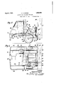
- FIG. 3 is a View similar to Figure 1, showing the cab moved forwardly to a position, wherein the engine and associated mechanism may be conveniently inspected and repaired.
- Figure 4 isa view in section, taken on line 4-4; of Figure 3, and looking in the direction of the arrows.
- Figure 5 is a View in section, taken on a transverse plane through the cab and looking rearwardly to show the elements thereof.
- igure 6 is a detail view showing the mechanism for moving the cab from its normal position to its extended position.
- Figure 7 is a view in section, taken on line 7-7 of Figure 6, and looking in the direction of the arrows.
- Figure 8 is a detail view showing the manner in which the cab is secured in position.
- Figure 9 is an end view of the mechanism shown in Figure 8.
- the motor vehicle is shown at 10, having a cab 11 and side frame members 12.
- the side frame members preferably support the engine 13 and carry the radiators 14, rear dash 15 and front dash 16.
- a removable hood 17 extends between these dashes and encloses the engine to reduce heat radiation therefrom into the" cab 11.
- brackets 18 Upon the side frame members 12 outrigger brackets 18 are mounted, these brackets carrying pedestals 19 upon whichtubular channels 20 are secured.
- the pedestals 19 at one side of the frame are formed with housings 21 within which a gear 22 is mounted upon a shaft 23.
- the end of shaft 23 is squared at 24 to receive any suitable wrench for turning the shaft and gear 22.
- tubular channels 20 Within the tubular channels 20, cylindrical shafts 25 are slidably received, the channels 20 being slotted at 26 and the shafts 25 being provided with upwardly extending flanges 27 u on which the cab 11 is mounted by means 0 flanges 28.
- ⁇ chain 31 preferably secures clamp 30 to the adjacent pedestal in order that the clamp may not be lost.
- a drivers seat 32 is mounted upon a stationary floor 33 carried by the chassis while the attendants seat 34 is mounted upon the floor 35 of the movable cab and advances therewith as clearly shown in Figure 3.
- rear wall 36 of the cab is provided with an aperture 37 which is adapted to cooperate with the rear dash 15 and provides a continuous rear dash for the control compartment within the cab when the latter is in its normal position.
- the aperture 37 is of such size as to enable it to clear the operators seat 32 and the steering column and wheel 38 in order that the cab may be advanced to its extended position.
- a cooperating Wall or partition member 39 is provided for cooperating with the forward dash 16 to afford a complete closure for the forward portion of the engine in order that a fan may be provided to direct cooling air over the engine and within the hood 17.
- the forward apron or mud guard 40 is preferably carried by the cab and thus advances therewith to expose the steering mechanism This apron or for convenient inspection. guard is provided with a slot 41 to afford access to the squared shaft 23 in order that the cab may be moved as outlinedabove.
- a cab slidably mounted thereon for forward longitudinal movement, a seat mounted on the frame and within the cab when the latter is in a normal position, and a seat mounted within the cab and movable therewith.
- a cab adapted to enclose the engine and radiator, partitions on the cab adapted to cooperate with the dashes to prevent communication between the interior of the cab and the engine and radiator, means to mount the cab slidably on the frame, a seat mounted on the frame and within the cab, and a seat mounted within the cab and slidable therewith.
Description
April 5, 1932. A. H. LEIPERT 1,852,464
MOVABLE CAB FOR MOTOR VEHICLES Filed April 9, 1931 s Sheets-Sheet 1 @i i/ It 0 A ril 5, 1932. A. H. LEIP ERT 1,352,464
MOVABLE CAB FOR MOTOR VEHICLES Filed April 9, 1951 s Sheets-Sheet 2 IN VENT OR izaromzxs April 1932- A. H. LEIPERT 1,852,464
MOVABLE CAB FOR MOTOR VEHICLES Filed April 9, 1931 3 $h89t$-$h99t 3 INVENTOR fluyasl H. lagjuarl,
chassis.
Patented Apr. 5, 1932 umran STATES PATENT OFFICE ,LUGUB'I H. LIIPIBT, OI COLLEGE 201181, NEW YORK, ASBIGNOB 20 INTERNATIONAL IO'IOB CODA-NY, OI NEW YORK, N. Y., A CORYOBATION OI DELAWARE IOLABLE CAB FOB MOTOR VEHICLES Application filed April 9, 1931.- sci-hi1 No. 528,751.,
the engine.
More s cifically, the invention includes a constructlon of the above character, where in provision is made for moving the cab in such fashion as to expose completely the engine and controlling elements in order that they may be conveniently installed and serviced.
There has recently been developed a type I of cab which completely encloses the engine and controlling mechanisms of the motor vehicle, placing the driver. and attendant along side of the engine and thus increasing the available ay load or platform area of the %here the elements are disposed in this fashion, the are quite compact and the installation and repair thereof requires free accessibility in order that the job may be commercially successful. An object of the present invention, accordingly is to provide a cab construction of this character, wherein free accessibility is provided for all of the controlling mechanism as well as the engine.
A further object of the invention is to provide a cab of the above character which may be conveniently moved into such position that the engine and associated elements may be fully exposed and conveniently inspected. A further object of the invention is to provide a device of the above character, wherein the dash, engine and radiators are rigidly 1 secured to the chassis and the cab is so constructed that it is adapted to cooperate with these elements to permit the cab to be moved forwardly hereof and out of the vertical planes thereof to permit accessibility for inspection and repair.
Further objects in the details of construction will be readily apparent as the description of the invention proceeds and reference will now be had to the accompanying drawings, wherein:
Figure 1 is a View in side elevation, showmg a vehicle cab constructed in accordance with the present invention.
Figure 2 is a view in front elevation of the cab of Figure 1.
- Figure 3 is a View similar to Figure 1, showing the cab moved forwardly to a position, wherein the engine and associated mechanism may be conveniently inspected and repaired.
Figure 4 isa view in section, taken on line 4-4; of Figure 3, and looking in the direction of the arrows.
Figure 5 is a View in section, taken on a transverse plane through the cab and looking rearwardly to show the elements thereof.
igure 6 is a detail view showing the mechanism for moving the cab from its normal position to its extended position.
Figure 7 is a view in section, taken on line 7-7 of Figure 6, and looking in the direction of the arrows.
Figure 8 is a detail view showing the manner in which the cab is secured in position.
Figure 9 is an end view of the mechanism shown in Figure 8. I
With reference to the above drawings, a
motor vehicle is shown at 10, having a cab 11 and side frame members 12. The side frame members preferably support the engine 13 and carry the radiators 14, rear dash 15 and front dash 16. A removable hood 17 extends between these dashes and encloses the engine to reduce heat radiation therefrom into the" cab 11.
Upon the side frame members 12 outrigger brackets 18 are mounted, these brackets carrying pedestals 19 upon whichtubular channels 20 are secured. The pedestals 19 at one side of the frame are formed with housings 21 within which a gear 22 is mounted upon a shaft 23. The end of shaft 23 is squared at 24 to receive any suitable wrench for turning the shaft and gear 22.
.Within the tubular channels 20, cylindrical shafts 25 are slidably received, the channels 20 being slotted at 26 and the shafts 25 being provided with upwardly extending flanges 27 u on which the cab 11 is mounted by means 0 flanges 28.
a clamp is applied to the shaft, movement of the latter is prevented and the cabis thus effectively locked in its normal position. A
\ chain 31 preferably secures clamp 30 to the adjacent pedestal in order that the clamp may not be lost.
A drivers seat 32is mounted upon a stationary floor 33 carried by the chassis while the attendants seat 34 is mounted upon the floor 35 of the movable cab and advances therewith as clearly shown in Figure 3. The
While the invention has been described with specific reference to the accompanying drawings, it is not to be limited, save as defined in the appended claims.
I claim as my invention:
1. In combination with a vehicle frame, a cab slidably mounted thereon for forward longitudinal movement, a seat mounted on the frame and within the cab when the latter is in a normal position, and a seat mounted within the cab and movable therewith.
2. In combination with a vehicle frame, an engine mounted thereon, a front dash, a radia tor mounted rearwardly of the engine, a rear dash separating the radiator and engine, and a hood over the engine and mounted between the dashes, a cab adapted to enclose the engine and radiator, partitions on the cab vent communication between the interior of the cab and the engine and radiators, and
means to mount the cab slidably on the frame.
3. In combination with a vehicle frame, an engine mounted thereon, a front dash, a radiator mounted rearwardly of the en 'ne, a rear dash separating the radiator an engine, and a hood over the engine and mounted between the dashes, a cab adapted to enclose the engine and radiator, partitions on the cab adapted to cooperate with the dashes to prevent communication between the interior of the cab and the engine and radiator, means to mount the cab slidably on the frame, a seat mounted on the frame and within the cab, and a seat mounted within the cab and slidable therewith.
This specification signed this 6th day of April, A. D. 1931.
. AUGUST H. LEIPERT.
adapted to cooperate with the dashes to pre-
Priority Applications (1)
| Application Number | Priority Date | Filing Date | Title |
|---|---|---|---|
| US528751A US1852464A (en) | 1931-04-09 | 1931-04-09 | Movable cab for motor vehicles |
Applications Claiming Priority (1)
| Application Number | Priority Date | Filing Date | Title |
|---|---|---|---|
| US528751A US1852464A (en) | 1931-04-09 | 1931-04-09 | Movable cab for motor vehicles |
Publications (1)
| Publication Number | Publication Date |
|---|---|
| US1852464A true US1852464A (en) | 1932-04-05 |
Family
ID=24107021
Family Applications (1)
| Application Number | Title | Priority Date | Filing Date |
|---|---|---|---|
| US528751A Expired - Lifetime US1852464A (en) | 1931-04-09 | 1931-04-09 | Movable cab for motor vehicles |
Country Status (1)
| Country | Link |
|---|---|
| US (1) | US1852464A (en) |
Cited By (19)
| Publication number | Priority date | Publication date | Assignee | Title |
|---|---|---|---|---|
| US2533752A (en) * | 1945-04-09 | 1950-12-12 | Alamagny Marcel Antoin Clement | Automobile vehicle |
| US2540214A (en) * | 1948-02-24 | 1951-02-06 | Armor Insulating Company | Driver's compartment for truck bodies |
| US2656214A (en) * | 1945-04-07 | 1953-10-20 | Alamagny Marcel Antoin Clement | Automobile body having pivoted end sections |
| US2700428A (en) * | 1948-10-01 | 1955-01-25 | Friedrich K H Nallinger | Motor vehicle with cab over engine |
| US2781102A (en) * | 1953-05-07 | 1957-02-12 | Cook Bros Equipment Co | Tilting hood and cab for motor vehicles |
| DE966740C (en) * | 1954-04-04 | 1957-09-26 | Fried Krupp Motoren Und Kraftw | Motor-driven garbage truck |
| US3929202A (en) * | 1975-04-21 | 1975-12-30 | Dean W Hobbensiefken | Vehicle cab configuration effecting reduction of air drag and enhancing storage space capacity and convenience |
| US3996999A (en) * | 1974-02-22 | 1976-12-14 | Deere & Company | Vehicle and hydraulic fluid reservoir combination |
| US4840423A (en) * | 1987-03-31 | 1989-06-20 | Mazda Motor Corporation | Front body structure of a motorcar |
| US20040195018A1 (en) * | 2003-04-02 | 2004-10-07 | Akira Inui | Floor arrangement for off-road vehicle |
| US20040195019A1 (en) * | 2003-04-02 | 2004-10-07 | Eiji Kato | Off road vehicle with air intake system |
| US20040195028A1 (en) * | 2003-04-02 | 2004-10-07 | Kazuhiko Izumi | Drive system for off-road vehicle |
| US20040206567A1 (en) * | 2003-04-02 | 2004-10-21 | Eiji Kato | Frame arrangement for off-road vehicle |
| US20040216945A1 (en) * | 2003-04-02 | 2004-11-04 | Akira Inui | Steering system for off-road vehicle |
| US20040231900A1 (en) * | 2003-04-02 | 2004-11-25 | Norihiko Tanaka | Air intake system for off-road vehicle |
| US20080015065A1 (en) * | 2003-04-02 | 2008-01-17 | Yamaha Hatsudoki Kabushiki Kaisha | Transmission for off-road vehicle |
| US7510199B2 (en) | 2003-04-02 | 2009-03-31 | Yamaha Hatsudoki Kabushiki Kaisha | Off-road vehicle with wheel suspension |
| CN104442613A (en) * | 2013-09-25 | 2015-03-25 | 光阳工业股份有限公司 | Multifunctional vehicle with safety blocking piece |
| TWI564180B (en) * | 2013-09-06 | 2017-01-01 | Kwang Yang Motor Co | Multi-function car with safety blanks |
-
1931
- 1931-04-09 US US528751A patent/US1852464A/en not_active Expired - Lifetime
Cited By (30)
| Publication number | Priority date | Publication date | Assignee | Title |
|---|---|---|---|---|
| US2656214A (en) * | 1945-04-07 | 1953-10-20 | Alamagny Marcel Antoin Clement | Automobile body having pivoted end sections |
| US2533752A (en) * | 1945-04-09 | 1950-12-12 | Alamagny Marcel Antoin Clement | Automobile vehicle |
| US2540214A (en) * | 1948-02-24 | 1951-02-06 | Armor Insulating Company | Driver's compartment for truck bodies |
| US2700428A (en) * | 1948-10-01 | 1955-01-25 | Friedrich K H Nallinger | Motor vehicle with cab over engine |
| US2781102A (en) * | 1953-05-07 | 1957-02-12 | Cook Bros Equipment Co | Tilting hood and cab for motor vehicles |
| DE966740C (en) * | 1954-04-04 | 1957-09-26 | Fried Krupp Motoren Und Kraftw | Motor-driven garbage truck |
| US3996999A (en) * | 1974-02-22 | 1976-12-14 | Deere & Company | Vehicle and hydraulic fluid reservoir combination |
| US3929202A (en) * | 1975-04-21 | 1975-12-30 | Dean W Hobbensiefken | Vehicle cab configuration effecting reduction of air drag and enhancing storage space capacity and convenience |
| US4840423A (en) * | 1987-03-31 | 1989-06-20 | Mazda Motor Corporation | Front body structure of a motorcar |
| US20040231900A1 (en) * | 2003-04-02 | 2004-11-25 | Norihiko Tanaka | Air intake system for off-road vehicle |
| US7438147B2 (en) | 2003-04-02 | 2008-10-21 | Yamaha Hatsudoki Kabushiki Kaisha | Transmission for off-road vehicle |
| US20040195028A1 (en) * | 2003-04-02 | 2004-10-07 | Kazuhiko Izumi | Drive system for off-road vehicle |
| US20040206567A1 (en) * | 2003-04-02 | 2004-10-21 | Eiji Kato | Frame arrangement for off-road vehicle |
| US20040216945A1 (en) * | 2003-04-02 | 2004-11-04 | Akira Inui | Steering system for off-road vehicle |
| US20040195018A1 (en) * | 2003-04-02 | 2004-10-07 | Akira Inui | Floor arrangement for off-road vehicle |
| US7287619B2 (en) * | 2003-04-02 | 2007-10-30 | Yamaha Hatsudoki Kabushiki Kaisha | Air intake system for off-road vehicle |
| US20080015065A1 (en) * | 2003-04-02 | 2008-01-17 | Yamaha Hatsudoki Kabushiki Kaisha | Transmission for off-road vehicle |
| US20080053727A1 (en) * | 2003-04-02 | 2008-03-06 | Yamaha Hatsudoki Kabushiki Kaisha | Air intake system for off-road vehicle |
| US7357211B2 (en) | 2003-04-02 | 2008-04-15 | Yamaha Hatsudoki Kabushiki Kaisha | Steering system for off-road vehicle |
| US7367417B2 (en) | 2003-04-02 | 2008-05-06 | Yamaha Hatsudoki Kabushiki Kaisha | Floor arrangement for off-road vehicle |
| US20040195019A1 (en) * | 2003-04-02 | 2004-10-07 | Eiji Kato | Off road vehicle with air intake system |
| US7506712B2 (en) | 2003-04-02 | 2009-03-24 | Yamaha Hatsudoki Kabushiki Kaisha | Off road vehicle with air intake system |
| US7510199B2 (en) | 2003-04-02 | 2009-03-31 | Yamaha Hatsudoki Kabushiki Kaisha | Off-road vehicle with wheel suspension |
| US7650959B2 (en) | 2003-04-02 | 2010-01-26 | Yamaha Hatsudoki Kabushiki Kaisha | Frame arrangement for off-road vehicle |
| US7690472B2 (en) | 2003-04-02 | 2010-04-06 | Yamaha Hatsudoki Kabushiki Kaisha | Transmission for off-road vehicle |
| US7690462B2 (en) | 2003-04-02 | 2010-04-06 | Yamaha Hatsudoki Kabushiki Kaisha | Off-road vehicle with air intake system |
| US7717206B2 (en) | 2003-04-02 | 2010-05-18 | Yamaha Hatsudoki Kabushiki Kaisha | Air intake system for off-road vehicle |
| TWI564180B (en) * | 2013-09-06 | 2017-01-01 | Kwang Yang Motor Co | Multi-function car with safety blanks |
| CN104442613A (en) * | 2013-09-25 | 2015-03-25 | 光阳工业股份有限公司 | Multifunctional vehicle with safety blocking piece |
| CN104442613B (en) * | 2013-09-25 | 2018-12-25 | 光阳工业股份有限公司 | Multi-function vehicle with safety baffle |
Similar Documents
| Publication | Publication Date | Title |
|---|---|---|
| US1852464A (en) | Movable cab for motor vehicles | |
| US4065170A (en) | Front section of a motor vehicle, especially of a passenger motor vehicle | |
| US2781102A (en) | Tilting hood and cab for motor vehicles | |
| US2753947A (en) | Forward mounted truck cab with a movable seat | |
| DE102019124362A1 (en) | LIDAR COOLING SYSTEM FOR AUTONOMOUS VEHICLES | |
| US2362453A (en) | Vehicle cab | |
| US2396506A (en) | Motor vehicle | |
| US3719245A (en) | Vehicle structure | |
| US2148308A (en) | Forward-tilting cab | |
| GB1313349A (en) | Motor vehicle structure | |
| US3174575A (en) | Mounting device for tilting integral hood and fender assembly | |
| US3288237A (en) | Motor vehicle | |
| US2253438A (en) | Tractor with gas producer arranged thereon | |
| US3086606A (en) | Motor vehicle front end structure | |
| US2266769A (en) | Motor vehicle body | |
| US3309020A (en) | Engine cooling and interior heating systems in motor vehicles | |
| US2104771A (en) | Storage battery installation | |
| US1856773A (en) | Vehicle construction | |
| NO783081L (en) | TRUCK, ESPECIALLY A SEMITRAILER OR VEHICLE FOR VOLUMINOES CARGO | |
| US1855642A (en) | Front wheel drive for two wheel chassis | |
| US2765863A (en) | Dashboard housing support for motor vehicle controls | |
| US1924030A (en) | Convertible automobile body | |
| US3194338A (en) | Instrument panels for vehicles | |
| US2133577A (en) | Battery installation | |
| US2871968A (en) | Luggage and spare wheel compartment structure on rear-engined vehicles |