US1854415A - Soap container - Google Patents
Soap container Download PDFInfo
- Publication number
- US1854415A US1854415A US476216A US47621630A US1854415A US 1854415 A US1854415 A US 1854415A US 476216 A US476216 A US 476216A US 47621630 A US47621630 A US 47621630A US 1854415 A US1854415 A US 1854415A
- Authority
- US
- United States
- Prior art keywords
- section
- sponge rubber
- skin
- rubber
- receptacle
- Prior art date
- Legal status (The legal status is an assumption and is not a legal conclusion. Google has not performed a legal analysis and makes no representation as to the accuracy of the status listed.)
- Expired - Lifetime
Links
Images
Classifications
-
- A—HUMAN NECESSITIES
- A47—FURNITURE; DOMESTIC ARTICLES OR APPLIANCES; COFFEE MILLS; SPICE MILLS; SUCTION CLEANERS IN GENERAL
- A47K—SANITARY EQUIPMENT NOT OTHERWISE PROVIDED FOR; TOILET ACCESSORIES
- A47K7/00—Body washing or cleaning implements
- A47K7/02—Bathing sponges, brushes, gloves, or similar cleaning or rubbing implements
- A47K7/03—Bathing sponges, brushes, gloves, or similar cleaning or rubbing implements containing soap or other cleaning ingredients, e.g. impregnated
Definitions
- 'llhis invention relates to soap containers and has for an object the provision of a new and improved article of this type and a process of making the same.
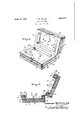
- FIG. 1 is a transverse sectional view through said embodiment.
- the embodiment herein shown comprises a base member A and a cover member B.
- the base member A comprises an elongated rectangular section of rubber sponge having the rind or skin removed from its bottom face 11 as well as from the side faces 12, thus to expose the cellular structure of the sponge rubber, while the upper face 13 has remaining thereon a skin or rind 14, resulting from the molding operation, and which extends entirely across the upper surface 13 of the section 10.
- a section 15 is rovided, consisting of a block of material similar to the section 10, but recessed as indicated at 16 so as to provide side and end walls 17 and 18 with exposed cut sponge surfaces, the lower surfaces of the walls 17 and 18 resting upon the skin or rind 14 of the section 1() along the marginal edges thereof, and being secured thereto, as by rubber cement, a fastening flap 19 being disposed between the sections 10 and 15 prior to the cementing operation.
- the upper surfaces of the walls 17 and 18 have portions 20 of the skin, resulting from the molding operation, remaining thereon.
- the cover member B comprises an elongated rectangular section 21 of sponge rubber of a size corresponding to the base member i A, and having exposed cut sponge rubber surfaces on all sides, whereby continuous porosity is obtained.
- a complemental section 22 Secured, as by rubber cement, to the inner surface of the section 21 is a complemental section 22, recessed as at 23 in the same manner as the section 15, and having portions of skin or rind 24 still remaining thereon.
- FIG. 1 is 'perspective view of an embodi- ⁇ A fastening tab 25 isto the cementing operation and is adapted to cooperate with the flap 19. It will be undervstood that all of the sections 10, 15, 21, and
- the base member A and cover member B are hingedly yconnected together by a continuous sheet of rubber 26, one end 27 of which is cemented to the adjacent skin 20 of the outer side wall 17 of the section 15, cemented @o also to form an imperforate lining 28 for the recess 16, cemented, as by rubber cement, to the opposite side wall 17 of the section 15, eX- tending thence continuously and secured to the skin portion 24 of the adjacent side wall 165 40 of the cover B, extending thence to provide a lining 29 for the recess 23 of the section 22, and having its end 30 secured to the outer surface ofthe skin 24of the opposite wall 40 of the section 22.
- the lining 29 is perforated 70 as at 31 to establish communication with the porous body of the section 21.
- the base member A and cover member B are thusl hingedly connected together, and may be fastened in closed position by means of the fastening members 19 and 25, the cavity provided by the combined recesses 23 and 16 serving as a chamber for the reception of soap or the like.
- a cake of soap may be placed within the receptacle and an vwater or liquid in the cavity may be readlly drained through the openings 31 and the porous section 21 of the cover B.
- the soap tray may be utilized as a bath sponge; that is by placing the cake of soap within the receptacle and securing the fastening members 19 and 25,. itis possible for moisture to pass through the porous section 21, and apertures 31, into the soap recess, generating a lather which also may pass through the porous section 21 of the cover member' B, thus enabling the porous section 21 ⁇ to be used as a soapy sponge to be applied to the object to be washed. Also dueV to the imperferate lining 26 of the base meme ber A, no moisture can pass from within the soap cavity through the section 10, and consequently the section 10 may be used as a rinsing sponge.
- I employ the following method. I form a relatively thin rectangular slab of vulcanized, cellular sponge rubber in a mold, the molded rubber being covered on all of its sides with a smooth skin or rind enclosing the sponge rubber body. This slab of material is then trimmed along its four edges so as to expose out sponge rubber surfaces, leaving the skin or rind intact upon its opposite broad faces.
- a receptacle corresponding to the base member A
- I irst split the slab lengthwise, substantially parallel to the broad surfaces thereof and form a base section, corresponding to the base section 'l0 having. the skin 14 thereon.
- the complemental section comprising the other portion of the slab, and corresponding to the section 15, is' then perforated by a suitable machine to form a. recess like the recess 16, leaving the skin or rind portions similar to 20, upon the complemental section 15.
- rl ⁇ he cut edges of the complemental section are then placed upon the surface 13 of the section, corresponding to the section 10, in abutting relation With the skin corresponding to the skin 14, and cemented in position.
- the cover member B is formed in identically thesame manner, except that the section, corresponding to the section 21 is cemented to the section 22, but the skin or rind,
- a receptacle comprising complemental recessed portions of sponge rubber with the cellular structure of the sponge rubber exposed along the exterior surfaces of said portions; and an inner lining for said ,complemental portions extending continuously from one to the other and providing a hinged connection for said portions.
- a receptacle having complemental recessed portions adapted to contain soap, and comprising defining walls of spongerubber with the cellular structure of the s onge rubber exposed along the exterior sur ace of said receptacle, one portion of said' sponge rubber having its skin removed to provide a porous area for the ingress and egress of 5 moisture with respect to said soap chamber;
- A. receptacle having complemental recessed portionsr providing a chamber for soap, and comprising deining Walls of sponge rubber, with the cellular structure of the sponge rubber exposed along the exterior surface of said receptacle; and an inner lining covering all the Walls of said portions.
- a sponge rubber article comprising: a recessed body portion having Walls of sponge rubber defining a receptacle, and a lining overlying the entire interior thereof.
- a sponge rubber article having a body portion comprising a plurality of sections of sponge rubber, provided with complementary recesses lining for said recesses one of said linings being perforated and united with the lining of the other section, said sections together forming the defining Walls of a receptacle.
- 'llhe method of making a sponge rubber article 'from sponge rubber block having a skin thereon which comprises: splitting the sponge rubber block into a plurality of pieces, Without removing the skin; perforating one of the split pieces; and uniting theperforated piece with another split piece to form a receptacle, with skin incorporated as reenforcing means, and to form the bottom of the receptacle.
- a sponge rubber receptacle comprising: a base portion; a peripheral sponge rubber Wall secured to said base portion; a sponge rubber cover for said receptacle; a sheet rubber hinge connecting' said cover with said Wall; and means or-releasably maintaining said cover closed.
- A. sponge rubber receptacle comprising: a sponge ru ber base portion having a reinforcing skin on one side only thereof; a peripheral sponge rubber Wall secured to the skin of said base portion; a sponge rubber cover ⁇ for said receptacle; a sheet rubber hinge connecting said cover with said Wall; and means for releasably maintaining said cover closed.
- a sponge rubber receptacle comprising: a sponge rubber base portion having a reinforcing skin on one side only thereof a peripheral sponge rubber Wall secured to the skin of said base portion; a sponge rubber cover for said receptacle having the skin removed from both sides thereof for the escape of moisture from said receptacle; and a sheet rulper hinge connecting said cover with said wa l0.
- a sponge rubber receptacle 'compneing: a sponge rubber base portion having a skin on one side only thereof1 for reinforcing said receptacle; a peripheral sponge rubber wall secured to the skin of said base portion; a sponge rubber cover for said receptacle having the'skin removed from both sides thereof; and a moisture impervious lining Lemme secured to said base portion and Walls and to said cover, and forming a flexible connection therebetween, the portion of the lining which is secured to said cover being provided with 'a plurality of apertures for the escape of moisture from said receptacle through the cellular structure of said cover.
- a sponge rubber receptacle comprising: a first section provided With a sponge rubber base portion; a peripheral sponge rubber Wall secured( to one side of said base portion; a second section provided with a sponge rubber base portion; a peripheral sponge rubber Wall secured to one slde of said second mentioned base portion for cooperation With the Wall of said first section; and a sheet rubber hinge secured to adjacent Walls of said first and second sections.
- a sponge rubber receptacle comprising: a first section provided with a sponge rubber base portion having a skin on one side only thereof; a peripheral sponge rubber Wall secured to the skin of said base portion; a sec- 0nd section provided With a sponge rubber base portion havingjthe skin removed from both sides thereof; a peripheral sponge rubber Wall secured to one side of the second mentioned base portion for cooperation with the Wall of said first section; and a sheet rubber hinge secured to adjacent Walls of said first and second sections.
- a rubber'sponge receptacle comprising: a plurality of sponge rubber sections provided with complementary recesses therein; a moisture impervious lining for. said recesses extending continuously from one section to the other section and forming a flexible hingeftherebetween, said lining being perforated adjacent one of said recesses for 'the escape of moisture through the contiguf ous cellular sponge rubber portion of the associated section.
- a rubber sponge receptacle comprising: a plurality of sponge rubber sections provided With complementary recesses therein; a moisture impervious molded lining having re-entrant portions secured Within said recesses and extending continuously from one section to the other section to form a fiexible hinge therebetween, one of the re-entrant portions of saidv lining being perforated for the escape of moisture through the contiguous cellular sponge rubber wall of the associated recess.
- a sponge rubber receptacle comprising: a plurality of sponge rubber sections provided with complementary recesses therein; a rubber lining having recesses formed therein secured Within the complementary recesses in said sections and having an intermediate portion forming a hinge connecting said sections.
- a sponge rubber,receptacle comprising: a plurality of sponge rubber sections provided with complementary recesses thererubber wall secured to said Ibase portion; a
- second section provided with a sponge rubber cover portion; a peripheral sponge rubber Wall secured to one side of said cover portion for cooperation with the Wall of said first section; and a rubber lining secured to the base and Wall portions of said first section and to the cover and Wall of said second section, and providing a flexible hinge connection between said sections.
- a sponge rubber receptacle comprising: a first section provided With a sponge rubber base portionhaving a skin on one side only thereof; a peripheral sponge rubber Wall secured to the skin side of said base portion, said skin reinforcing said receptacle; a second section provided With a sponge rubber cover portion; a peripheral sponge rubber Wall secured to one side of said cover portion for cooperation With the Wall of said first section; and a rubber lining secured to the base and Wall portions of said first section and to the cover and Wall of said second section, and providing a flexible hinge connection between said sections.
- a sponge rubber receptacle comprising: a first section provided with a sponge rubber base portion; a peripheral sponge rubber Wall secured to one side of said base portion; a second section provid-edwith a sponge rubber cover portion having the skin removed from both sides thereof; a peripheral sponge rubber Wall secured to one side of said cover portion for cooperation Withthe Wall of said first section and a rubber lining secured to the base and Wall portions of said first section and to the cover and Wall of said second section, and providing a flexible hinge connection between said sections, said lining being perforated adjacent the cover portion of said second section for the escape of moisture through the cover portion.
- a sponge rubber receptacle comprising: a first 'section provided with a sponge SCD signature.
Description
April 19, 1932. T@ Wi WLLER 1,854,415
SOAP CONTAINER Filed Aug. 18, 1930 'raam Kaman-R lNvLN-roqu B w21/@w Patented Apr. 1, 1932 l UNH @MAS MILLER, F ASHLAND, OHIO, ASSIGNOR T0 THE FAULTLESS RUBBER COM- PANY, 0F ASHLAN D, OHIO, A CORPORATION 0F OHIO SOAP CONTAINER Application led August 18, 1930. Serial No. 476,216.
'llhis invention relates to soap containers and has for an object the provision of a new and improved article of this type and a process of making the same.
ln thedrawings accompanying this specication and forming a part of this application l have shown, for purposes of illustration, certain forms which my invention may assume, and in these drawings: l0
ment of the invention, while Figure 2 is a transverse sectional view through said embodiment. l The embodiment herein shown comprises a base member A and a cover member B. The base member A comprises an elongated rectangular section of rubber sponge having the rind or skin removed from its bottom face 11 as well as from the side faces 12, thus to expose the cellular structure of the sponge rubber, while the upper face 13 has remaining thereon a skin or rind 14, resulting from the molding operation, and which extends entirely across the upper surface 13 of the section 10. A section 15 is rovided, consisting of a block of material similar to the section 10, but recessed as indicated at 16 so as to provide side and end walls 17 and 18 with exposed cut sponge surfaces, the lower surfaces of the walls 17 and 18 resting upon the skin or rind 14 of the section 1() along the marginal edges thereof, and being secured thereto, as by rubber cement, a fastening flap 19 being disposed between the sections 10 and 15 prior to the cementing operation. The upper surfaces of the walls 17 and 18 have portions 20 of the skin, resulting from the molding operation, remaining thereon.
The cover member B comprises an elongated rectangular section 21 of sponge rubber of a size corresponding to the base member i A, and having exposed cut sponge rubber surfaces on all sides, whereby continuous porosity is obtained. Secured, as by rubber cement, to the inner surface of the section 21 is a complemental section 22, recessed as at 23 in the same manner as the section 15, and having portions of skin or rind 24 still remaining thereon.
secured between the sections 21 and 22 prior Figure 1 is 'perspective view of an embodi-` A fastening tab 25 isto the cementing operation and is adapted to cooperate with the flap 19. It will be undervstood that all of the sections 10, 15, 21, and
22 may be of differently colored sponge rubber if desired.
The base member A and cover member B are hingedly yconnected together by a continuous sheet of rubber 26, one end 27 of which is cemented to the adjacent skin 20 of the outer side wall 17 of the section 15, cemented @o also to form an imperforate lining 28 for the recess 16, cemented, as by rubber cement, to the opposite side wall 17 of the section 15, eX- tending thence continuously and secured to the skin portion 24 of the adjacent side wall 165 40 of the cover B, extending thence to provide a lining 29 for the recess 23 of the section 22, and having its end 30 secured to the outer surface ofthe skin 24of the opposite wall 40 of the section 22. The lining 29 is perforated 70 as at 31 to establish communication with the porous body of the section 21.
The base member A and cover member B are thusl hingedly connected together, and may be fastened in closed position by means of the fastening members 19 and 25, the cavity provided by the combined recesses 23 and 16 serving as a chamber for the reception of soap or the like. l
In use, a cake of soap may be placed within the receptacle and an vwater or liquid in the cavity may be readlly drained through the openings 31 and the porous section 21 of the cover B. Also the soap tray may be utilized as a bath sponge; that is by placing the cake of soap within the receptacle and securing the fastening members 19 and 25,. itis possible for moisture to pass through the porous section 21, and apertures 31, into the soap recess, generating a lather which also may pass through the porous section 21 of the cover member' B, thus enabling the porous section 21`to be used as a soapy sponge to be applied to the object to be washed. Also dueV to the imperferate lining 26 of the base meme ber A, no moisture can pass from within the soap cavity through the section 10, and consequently the section 10 may be used as a rinsing sponge.
In providing the base member A and cover member B I employ the following method. I form a relatively thin rectangular slab of vulcanized, cellular sponge rubber in a mold, the molded rubber being covered on all of its sides with a smooth skin or rind enclosing the sponge rubber body. This slab of material is then trimmed along its four edges so as to expose out sponge rubber surfaces, leaving the skin or rind intact upon its opposite broad faces.
In forming a receptacle, corresponding to the base member A, I irst split the slab lengthwise, substantially parallel to the broad surfaces thereof and form a base section, corresponding to the base section 'l0 having. the skin 14 thereon. |The complemental section, comprising the other portion of the slab, and corresponding to the section 15, is' then perforated by a suitable machine to form a. recess like the recess 16, leaving the skin or rind portions similar to 20, upon the complemental section 15. rl`he cut edges of the complemental section are then placed upon the surface 13 of the section, corresponding to the section 10, in abutting relation With the skin corresponding to the skin 14, and cemented in position.
The cover member B is formed in identically thesame manner, except that the section, corresponding to the section 21 is cemented to the section 22, but the skin or rind,
which would correspond to the skin or rind 14 is removed, in order to render the section 21 porous. i*
It will be apparent to those skilled in the art that the embodiments herein described accomplish at least the principal objects of the invention; it also will be apparent that said embodiments have advantages and may be applied to uses otherthan those herein v mentioned; furthermore that various changes and modifications ma be made Within the scope of the claims without departing from the spirit of the invention; accordingly it will be understood that the embodiments herein disclosed are illustrative only and that the invention is not limited thereto.
I claim:
1. A receptacle comprising complemental recessed portions of sponge rubber with the cellular structure of the sponge rubber exposed along the exterior surfaces of said portions; and an inner lining for said ,complemental portions extending continuously from one to the other and providing a hinged connection for said portions.
2. A receptacle having complemental recessed portions adapted to contain soap, and comprising defining walls of spongerubber with the cellular structure of the s onge rubber exposed along the exterior sur ace of said receptacle, one portion of said' sponge rubber having its skin removed to provide a porous area for the ingress and egress of 5 moisture with respect to said soap chamber;
asse-,are
and an inner lining for said portions apertured opposite said porous area..
3. A. receptacle having complemental recessed portionsr providing a chamber for soap, and comprising deining Walls of sponge rubber, with the cellular structure of the sponge rubber exposed along the exterior surface of said receptacle; and an inner lining covering all the Walls of said portions.
d. A sponge rubber article comprising: a recessed body portion having Walls of sponge rubber defining a receptacle, and a lining overlying the entire interior thereof.
5. A sponge rubber article having a body portion comprising a plurality of sections of sponge rubber, provided with complementary recesses lining for said recesses one of said linings being perforated and united with the lining of the other section, said sections together forming the defining Walls of a receptacle.
6. 'llhe method of making a sponge rubber article 'from sponge rubber block having a skin thereon, which comprises: splitting the sponge rubber block into a plurality of pieces, Without removing the skin; perforating one of the split pieces; and uniting theperforated piece with another split piece to form a receptacle, with skin incorporated as reenforcing means, and to form the bottom of the receptacle.
7. A sponge rubber receptacle comprising: a base portion; a peripheral sponge rubber Wall secured to said base portion; a sponge rubber cover for said receptacle; a sheet rubber hinge connecting' said cover with said Wall; and means or-releasably maintaining said cover closed.
8. A. sponge rubber receptacle comprising: a sponge ru ber base portion having a reinforcing skin on one side only thereof; a peripheral sponge rubber Wall secured to the skin of said base portion; a sponge rubber cover` for said receptacle; a sheet rubber hinge connecting said cover with said Wall; and means for releasably maintaining said cover closed.
9. A sponge rubber receptacle comprising: a sponge rubber base portion having a reinforcing skin on one side only thereof a peripheral sponge rubber Wall secured to the skin of said base portion; a sponge rubber cover for said receptacle having the skin removed from both sides thereof for the escape of moisture from said receptacle; and a sheet rulper hinge connecting said cover with said wa l0. A sponge rubber receptacle 'compneing: a sponge rubber base portion having a skin on one side only thereof1 for reinforcing said receptacle; a peripheral sponge rubber wall secured to the skin of said base portion; a sponge rubber cover for said receptacle having the'skin removed from both sides thereof; and a moisture impervious lining Lemme secured to said base portion and Walls and to said cover, and forming a flexible connection therebetween, the portion of the lining which is secured to said cover being provided with 'a plurality of apertures for the escape of moisture from said receptacle through the cellular structure of said cover.
11. A sponge rubber receptacle comprising: a first section provided With a sponge rubber base portion; a peripheral sponge rubber Wall secured( to one side of said base portion; a second section provided with a sponge rubber base portion; a peripheral sponge rubber Wall secured to one slde of said second mentioned base portion for cooperation With the Wall of said first section; and a sheet rubber hinge secured to adjacent Walls of said first and second sections.
12. A sponge rubber receptacle comprising: a first section provided with a sponge rubber base portion having a skin on one side only thereof; a peripheral sponge rubber Wall secured to the skin of said base portion; a sec- 0nd section provided With a sponge rubber base portion havingjthe skin removed from both sides thereof; a peripheral sponge rubber Wall secured to one side of the second mentioned base portion for cooperation with the Wall of said first section; and a sheet rubber hinge secured to adjacent Walls of said first and second sections.
13. A rubber'sponge receptacle comprising: a plurality of sponge rubber sections provided with complementary recesses therein; a moisture impervious lining for. said recesses extending continuously from one section to the other section and forming a flexible hingeftherebetween, said lining being perforated adjacent one of said recesses for 'the escape of moisture through the contiguf ous cellular sponge rubber portion of the associated section.
14. A rubber sponge receptacle comprising: a plurality of sponge rubber sections provided With complementary recesses therein; a moisture impervious molded lining having re-entrant portions secured Within said recesses and extending continuously from one section to the other section to form a fiexible hinge therebetween, one of the re-entrant portions of saidv lining being perforated for the escape of moisture through the contiguous cellular sponge rubber wall of the associated recess.
15. A sponge rubber receptacle comprising: a plurality of sponge rubber sections provided with complementary recesses therein; a rubber lining having recesses formed therein secured Within the complementary recesses in said sections and having an intermediate portion forming a hinge connecting said sections.
16. A sponge rubber,receptaclecomprising: a plurality of sponge rubber sections provided with complementary recesses thererubber wall secured to said Ibase portion; a
second section provided with a sponge rubber cover portion; a peripheral sponge rubber Wall secured to one side of said cover portion for cooperation with the Wall of said first section; and a rubber lining secured to the base and Wall portions of said first section and to the cover and Wall of said second section, and providing a flexible hinge connection between said sections.
18. A sponge rubber receptacle comprising: a first section provided With a sponge rubber base portionhaving a skin on one side only thereof; a peripheral sponge rubber Wall secured to the skin side of said base portion, said skin reinforcing said receptacle; a second section provided With a sponge rubber cover portion; a peripheral sponge rubber Wall secured to one side of said cover portion for cooperation With the Wall of said first section; and a rubber lining secured to the base and Wall portions of said first section and to the cover and Wall of said second section, and providing a flexible hinge connection between said sections.
19. A sponge rubber receptacle comprising: a first section provided with a sponge rubber base portion; a peripheral sponge rubber Wall secured to one side of said base portion; a second section provid-edwith a sponge rubber cover portion having the skin removed from both sides thereof; a peripheral sponge rubber Wall secured to one side of said cover portion for cooperation Withthe Wall of said first section and a rubber lining secured to the base and Wall portions of said first section and to the cover and Wall of said second section, and providinga flexible hinge connection between said sections, said lining being perforated adjacent the cover portion of said second section for the escape of moisture through the cover portion.
20. A sponge rubber receptacle comprising: a first 'section provided with a sponge SCD signature.
THOMAS W. MILLER.
Priority Applications (1)
| Application Number | Priority Date | Filing Date | Title |
|---|---|---|---|
| US476216A US1854415A (en) | 1930-08-18 | 1930-08-18 | Soap container |
Applications Claiming Priority (1)
| Application Number | Priority Date | Filing Date | Title |
|---|---|---|---|
| US476216A US1854415A (en) | 1930-08-18 | 1930-08-18 | Soap container |
Publications (1)
| Publication Number | Publication Date |
|---|---|
| US1854415A true US1854415A (en) | 1932-04-19 |
Family
ID=23890968
Family Applications (1)
| Application Number | Title | Priority Date | Filing Date |
|---|---|---|---|
| US476216A Expired - Lifetime US1854415A (en) | 1930-08-18 | 1930-08-18 | Soap container |
Country Status (1)
| Country | Link |
|---|---|
| US (1) | US1854415A (en) |
Cited By (11)
| Publication number | Priority date | Publication date | Assignee | Title |
|---|---|---|---|---|
| US2526076A (en) * | 1946-03-07 | 1950-10-17 | Kalamazoo Vegets Le Parchment | Washcloth, dishcloth, scouring cloth, and the like, and method of making the same |
| US2565939A (en) * | 1947-04-10 | 1951-08-28 | Roderic T Wriston | Lined waterproof container |
| US2588773A (en) * | 1948-03-22 | 1952-03-11 | Andrew G Smith | Soap holding and lathering sponge |
| US2899780A (en) * | 1959-08-18 | Scouring pad containing dispensable substance | ||
| US3403713A (en) * | 1966-02-23 | 1968-10-01 | Nash Hammond Inc | Cushioning container |
| US5704723A (en) * | 1996-08-29 | 1998-01-06 | Salisian; Harold W. | Soap dispensing device |
| US6623830B2 (en) * | 2001-05-26 | 2003-09-23 | Marilyn S. Lewis | Soap receptacle |
| US8142095B1 (en) * | 2007-11-27 | 2012-03-27 | Cutler Renee J | Sponge with soap sleeve and method of use thereof |
| US20180263430A1 (en) * | 2017-03-17 | 2018-09-20 | Mehdi Terfous | Soap Holder |
| US10788263B1 (en) * | 2018-02-17 | 2020-09-29 | Clearman Labs, LLC | Drying, space-saving soap bar container methods, systems, and devices |
| US20220296049A1 (en) * | 2021-03-19 | 2022-09-22 | Andrew Bordin | Wall mountable soap dish assembly and methods of making and using the same |
-
1930
- 1930-08-18 US US476216A patent/US1854415A/en not_active Expired - Lifetime
Cited By (12)
| Publication number | Priority date | Publication date | Assignee | Title |
|---|---|---|---|---|
| US2899780A (en) * | 1959-08-18 | Scouring pad containing dispensable substance | ||
| US2526076A (en) * | 1946-03-07 | 1950-10-17 | Kalamazoo Vegets Le Parchment | Washcloth, dishcloth, scouring cloth, and the like, and method of making the same |
| US2565939A (en) * | 1947-04-10 | 1951-08-28 | Roderic T Wriston | Lined waterproof container |
| US2588773A (en) * | 1948-03-22 | 1952-03-11 | Andrew G Smith | Soap holding and lathering sponge |
| US3403713A (en) * | 1966-02-23 | 1968-10-01 | Nash Hammond Inc | Cushioning container |
| US5704723A (en) * | 1996-08-29 | 1998-01-06 | Salisian; Harold W. | Soap dispensing device |
| US6623830B2 (en) * | 2001-05-26 | 2003-09-23 | Marilyn S. Lewis | Soap receptacle |
| US8142095B1 (en) * | 2007-11-27 | 2012-03-27 | Cutler Renee J | Sponge with soap sleeve and method of use thereof |
| US20180263430A1 (en) * | 2017-03-17 | 2018-09-20 | Mehdi Terfous | Soap Holder |
| US10788263B1 (en) * | 2018-02-17 | 2020-09-29 | Clearman Labs, LLC | Drying, space-saving soap bar container methods, systems, and devices |
| US20220296049A1 (en) * | 2021-03-19 | 2022-09-22 | Andrew Bordin | Wall mountable soap dish assembly and methods of making and using the same |
| US11937747B2 (en) * | 2021-03-19 | 2024-03-26 | Andrew Bordin | Wall mountable soap dish assembly and methods of making and using the same |
Similar Documents
| Publication | Publication Date | Title |
|---|---|---|
| US1854415A (en) | Soap container | |
| US2324735A (en) | Composite rubber article and method of producing same | |
| US2515113A (en) | Method of producing molded fiber articles | |
| US4062792A (en) | Soap cake construction and manufacture | |
| US2704448A (en) | Diaper washboard | |
| KR840004887A (en) | Integral seats and methods | |
| US1641650A (en) | Toilet kit | |
| US4318213A (en) | Method of making resilient seats and cover lids therefor for water closets | |
| US3988789A (en) | Resilient seats and cover lids therefor for water closets | |
| US1397611A (en) | Bath-brush | |
| US2043327A (en) | Heat exchanging container | |
| US1778270A (en) | Sponge rubber | |
| US1552720A (en) | Cover for receptacles | |
| US20200281744A1 (en) | Breast prostheses | |
| JPS58101027A (en) | Manufacture of molded sheet with skin integrated therewith and the same | |
| US2058213A (en) | Integral resilient cleansing member | |
| JPS58134468U (en) | Medication refill for flush toilets | |
| IE810334L (en) | Cheese mould | |
| GB2216842A (en) | Mold steel for foamed plastic molding | |
| GB913026A (en) | Improvements in or relating to partitions for stock vats for moulding pulp articles | |
| JPH0120916Y2 (en) | ||
| US2089598A (en) | Floor mat | |
| JPH038585Y2 (en) | ||
| US2266844A (en) | Mold | |
| US1472646A (en) | Molding flask |