US18569A - Device fob pobming bound tenons on window-blind slats - Google Patents
Device fob pobming bound tenons on window-blind slats Download PDFInfo
- Publication number
- US18569A US18569A US18569DA US18569A US 18569 A US18569 A US 18569A US 18569D A US18569D A US 18569DA US 18569 A US18569 A US 18569A
- Authority
- US
- United States
- Prior art keywords
- cutters
- window
- pobming
- tenons
- bound
- Prior art date
- Legal status (The legal status is an assumption and is not a legal conclusion. Google has not performed a legal analysis and makes no representation as to the accuracy of the status listed.)
- Expired - Lifetime
Links
- 210000002832 Shoulder Anatomy 0.000 description 30
- 241000272517 Anseriformes Species 0.000 description 2
- 240000001624 Espostoa lanata Species 0.000 description 2
- 210000001138 Tears Anatomy 0.000 description 2
- 239000002023 wood Substances 0.000 description 2
Images
Classifications
-
- B—PERFORMING OPERATIONS; TRANSPORTING
- B23—MACHINE TOOLS; METAL-WORKING NOT OTHERWISE PROVIDED FOR
- B23D—PLANING; SLOTTING; SHEARING; BROACHING; SAWING; FILING; SCRAPING; LIKE OPERATIONS FOR WORKING METAL BY REMOVING MATERIAL, NOT OTHERWISE PROVIDED FOR
- B23D21/00—Machines or devices for shearing or cutting tubes
- B23D21/04—Tube-severing machines with rotating tool-carrier
-
- Y—GENERAL TAGGING OF NEW TECHNOLOGICAL DEVELOPMENTS; GENERAL TAGGING OF CROSS-SECTIONAL TECHNOLOGIES SPANNING OVER SEVERAL SECTIONS OF THE IPC; TECHNICAL SUBJECTS COVERED BY FORMER USPC CROSS-REFERENCE ART COLLECTIONS [XRACs] AND DIGESTS
- Y10—TECHNICAL SUBJECTS COVERED BY FORMER USPC
- Y10T—TECHNICAL SUBJECTS COVERED BY FORMER US CLASSIFICATION
- Y10T408/00—Cutting by use of rotating axially moving tool
- Y10T408/36—Machine including plural tools
- Y10T408/375—Coaxial tools
- Y10T408/378—Coaxial, opposed tools
- Y10T408/3796—Coaxial, opposed tools with interconnected means to simultaneously feed tools
Definitions
- a slat is to be placed directly between the two journal cutters L, L, when they are at their greatest distance asunder, any suitable device or contrivance being used for supporting such slat in its proper position.
- the two carriages are to be made to approach one another, so as to force the shoulder cutters simultaneously against opposite sides of the blind slat, and while they approach one anotherl the tubular journal cutter or cutters will be forced forward or toward the shoulder cutters, and the two kinds of cutters cooperating will form upon j the blind slat, the round journal or ournals and the shoulders thereof.
- the awls will pierce the holes for the staples. All this having been accomplished, the motions of the mechanism are next to be reversed, or its cutters caused to recede from one another until the blind slat is relieved from them and they are restored to a proper position for the application of another Slat to the machine.
- Each connecting rod E is formed with an angular bend and with the longer part f, elevated above the shorter part, g, and so that when the two connecting rods of each lever, F, are moved toward one another the short part, g, of eachrod shall pass underneath the longer part, f, of the other connecting rod.
- This mode of making the connecting rods or bars, E causes the shoulder cutters to cut into the slat to the depth required, and next to recede a short distance from it before the journal cutter has completed its forward movement. This action of the shoulder cutters enables the shoulder and journal to be cut clean and without any burV or slivers being left at their junction.
- the positions of the parts of the machine when the shoulder cutters are closed are exhibited in the top view of the machine shown in Fig.
- FIG. 5 exhibits the positions of such parts immediately after the recession of the shoulder cutters and the journal cutters have been driven home to the shoulders, in which case the longer parts f, f, of the adjacent connecting bars, E, E, are brought into contact with each other.
Description
lUNITED sTATEs PATENT l Ormea.
THOMAS C. BALL, OF KEENE, NEW HAMPSHIRE.
DEVICE FOR FORMING ROUND TENON S 0N WINDOW-BLIND SLATS.
Specification of Letters Patent No. 18,569, dated November 10, 1857.
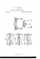
To all 'whom it may concern Be it known that I, THOMAS C. BALL, of Keene, in the county of Cheshire and State of New Hampshire, have invented a new and useful Machine for Forming Journals on Rotary Slats for Venetian Blinds and Priclring Staple-Holes in said Slats; and I do hereby declare that the same is fully described and represented in the following specification and the accompanying drawings, of which- Figure 1 exhibits a top view of the said machine. Fig. 2, a vertical central and longitudinal Vsection of it. Fig. 3 is a vertical, central and transverse section of it.
In these drawings A, is the framework of the machine, it being made with two transverse and parallel rails B, B, upon which rest and slide two carriages or bars C, D, which are arranged parallel to one another and in other respects as seen in the drawings. By means of four connecting rods E, E, E, E, disposed as seen in Figs. 1 and 2, and jointed to the carriages C, D, and to two levers F, F, fixed respectively on the upper ends of two vertical shafts Gr, G, the said carriages can be made simultaneously to approach toward or recede from each other whenever` the two shafts are simultaneously put in rotation. On each shaft there is a pulley H, around both of which pulleys a crossed endless band I, travels.
Shoulder cutters K, K, K, K, are carried by and made to project from the two carriages C, D, as seen in the drawings, and to operate in connection with tubular sliding journal cutters, L, L, arranged as seen in Figs. l, 2 and 3, and supported in stationary puppet heads M, M. To each of these lat'- ter cutters a longitudinal movement is given by means of a rod a, and a crank pin b, which connect the cutter with the adjacent lever F, and so that by the movement of said lever in such manner as to cause the two carriages to approach one another the cutter L, shall be moved toward the ournal cutters.
Midway between the two shoulder cut ters of one of the carriages, there are afw fixed to said carriage two awls or piercers N,.N, so arranged as to be caused to puncture the edge of the blind slat, while the carriages are made to approach one another, the said awls or piercers being for the purpose of making the staple holes of the blind slat.
In operating with the above described machine, a slat is to be placed directly between the two journal cutters L, L, when they are at their greatest distance asunder, any suitable device or contrivance being used for supporting such slat in its proper position. This done, the two carriages are to be made to approach one another, so as to force the shoulder cutters simultaneously against opposite sides of the blind slat, and while they approach one anotherl the tubular journal cutter or cutters will be forced forward or toward the shoulder cutters, and the two kinds of cutters cooperating will form upon j the blind slat, the round journal or ournals and the shoulders thereof. During the same the awls will pierce the holes for the staples. All this having been accomplished, the motions of the mechanism are next to be reversed, or its cutters caused to recede from one another until the blind slat is relieved from them and they are restored to a proper position for the application of another Slat to the machine.
Each connecting rod E, is formed with an angular bend and with the longer part f, elevated above the shorter part, g, and so that when the two connecting rods of each lever, F, are moved toward one another the short part, g, of eachrod shall pass underneath the longer part, f, of the other connecting rod. This mode of making the connecting rods or bars, E, causes the shoulder cutters to cut into the slat to the depth required, and next to recede a short distance from it before the journal cutter has completed its forward movement. This action of the shoulder cutters enables the shoulder and journal to be cut clean and without any burV or slivers being left at their junction. The positions of the parts of the machine when the shoulder cutters are closed are exhibited in the top view of the machine shown in Fig. 4, while Fig. 5 exhibits the positions of such parts immediately after the recession of the shoulder cutters and the journal cutters have been driven home to the shoulders, in which case the longer parts f, f, of the adjacent connecting bars, E, E, are brought into contact with each other.
I am aware that a machine for forming journals of blind slats and pricling the staple holes of such slats has been constructed with rotary hollow augers for forming the journals and shoulders. Such contrivances are objectionable, as they tear the wood more or less and leave it with ragged edges, Which require to be reduced sliding tubular journal cutters to operate by other tools. My machine makes smooth together substantially as specified.
j ournais and shoulders Which require no In testimony whereof, I have hereunto subsequent finishing. set my signature this tenth day of January, 5 NOW I do not claim the eombililation of A. D. 1856.
machinery for rieking the staple oies and forming the jolliprnals and shoulders, but THOS' C BALL' What I do claim as my improvement is "Witnesses: The arrangement and combination of siid- R. H. EDDY,
10 ing shoulder cutters or their equivalents and F. P. HALE, J r.
Publications (1)
| Publication Number | Publication Date |
|---|---|
| US18569A true US18569A (en) | 1857-11-10 |
Family
ID=2081994
Family Applications (1)
| Application Number | Title | Priority Date | Filing Date |
|---|---|---|---|
| US18569D Expired - Lifetime US18569A (en) | Device fob pobming bound tenons on window-blind slats |
Country Status (1)
| Country | Link |
|---|---|
| US (1) | US18569A (en) |
Cited By (1)
| Publication number | Priority date | Publication date | Assignee | Title |
|---|---|---|---|---|
| US20040177258A1 (en) * | 2003-03-03 | 2004-09-09 | Ong Peng T. | Secure object for convenient identification |
-
0
- US US18569D patent/US18569A/en not_active Expired - Lifetime
Cited By (1)
| Publication number | Priority date | Publication date | Assignee | Title |
|---|---|---|---|---|
| US20040177258A1 (en) * | 2003-03-03 | 2004-09-09 | Ong Peng T. | Secure object for convenient identification |
Similar Documents
| Publication | Publication Date | Title |
|---|---|---|
| US18569A (en) | Device fob pobming bound tenons on window-blind slats | |
| US29996A (en) | Machine eor jointing staves | |
| US13574A (en) | Dovetail-key cutter | |
| US16332A (en) | Improved mortising-machine | |
| US10906A (en) | Eotaey shingle-machine | |
| US11915A (en) | Machine for making head part of shovel-handles | |
| US10395A (en) | Machine poe cutting hand-rails | |
| US14289A (en) | Machine fob tenoning window-blinds | |
| US11777A (en) | Machine for | |
| US10403A (en) | cum mings | |
| US82801A (en) | Improvement in blind-slat-tenoning machine | |
| US10362A (en) | Steaw-ctttter | |
| US18535A (en) | cambridge | |
| US15423A (en) | Device ik stave machinery | |
| US13271A (en) | Machine for mortising window-blinds | |
| US4936A (en) | Mobtising-machine | |
| US13230A (en) | Stave-machine | |
| US16849A (en) | Machine foe | |
| US16095A (en) | Stave-jointer | |
| US23909A (en) | Straw-cutter | |
| US25603A (en) | James decker | |
| USRE409E (en) | Stephen k | |
| US18599A (en) | Lateral eeed-motlow for sawiktg-mills | |
| US193428A (en) | Improvement in machines for making wooden pins | |
| US16742A (en) | Shingle-machine |