US1857084A - Air pressure dispenser - Google Patents
Air pressure dispenser Download PDFInfo
- Publication number
- US1857084A US1857084A US281306A US28130628A US1857084A US 1857084 A US1857084 A US 1857084A US 281306 A US281306 A US 281306A US 28130628 A US28130628 A US 28130628A US 1857084 A US1857084 A US 1857084A
- Authority
- US
- United States
- Prior art keywords
- tank
- conduit
- pressure
- air
- tanks
- Prior art date
- Legal status (The legal status is an assumption and is not a legal conclusion. Google has not performed a legal analysis and makes no representation as to the accuracy of the status listed.)
- Expired - Lifetime
Links
- 239000007788 liquid Substances 0.000 description 26
- 239000000463 material Substances 0.000 description 15
- 238000009826 distribution Methods 0.000 description 8
- 239000002904 solvent Substances 0.000 description 8
- 239000004922 lacquer Substances 0.000 description 7
- 239000003973 paint Substances 0.000 description 7
- 239000002966 varnish Substances 0.000 description 7
- 239000012530 fluid Substances 0.000 description 5
- 238000007599 discharging Methods 0.000 description 4
- 239000007921 spray Substances 0.000 description 4
- 238000005507 spraying Methods 0.000 description 4
- 238000003756 stirring Methods 0.000 description 4
- 238000013019 agitation Methods 0.000 description 3
- 238000010276 construction Methods 0.000 description 3
- 230000001419 dependent effect Effects 0.000 description 3
- 239000000203 mixture Substances 0.000 description 3
- 210000002445 nipple Anatomy 0.000 description 3
- 239000000645 desinfectant Substances 0.000 description 2
- 239000003599 detergent Substances 0.000 description 2
- 230000001939 inductive effect Effects 0.000 description 2
- 239000002917 insecticide Substances 0.000 description 2
- 230000004048 modification Effects 0.000 description 2
- 238000012986 modification Methods 0.000 description 2
- 239000000725 suspension Substances 0.000 description 2
- 229910000906 Bronze Inorganic materials 0.000 description 1
- 208000036366 Sensation of pressure Diseases 0.000 description 1
- 238000009825 accumulation Methods 0.000 description 1
- 239000010974 bronze Substances 0.000 description 1
- 239000003638 chemical reducing agent Substances 0.000 description 1
- KUNSUQLRTQLHQQ-UHFFFAOYSA-N copper tin Chemical group [Cu].[Sn] KUNSUQLRTQLHQQ-UHFFFAOYSA-N 0.000 description 1
- 230000008878 coupling Effects 0.000 description 1
- 238000010168 coupling process Methods 0.000 description 1
- 238000005859 coupling reaction Methods 0.000 description 1
- 239000000428 dust Substances 0.000 description 1
- 230000000694 effects Effects 0.000 description 1
- 238000004880 explosion Methods 0.000 description 1
- 239000002360 explosive Substances 0.000 description 1
- 210000004907 gland Anatomy 0.000 description 1
- 239000011521 glass Substances 0.000 description 1
- 239000004615 ingredient Substances 0.000 description 1
- 238000009434 installation Methods 0.000 description 1
- 238000012856 packing Methods 0.000 description 1
- 239000002245 particle Substances 0.000 description 1
- 238000007790 scraping Methods 0.000 description 1
- 238000005406 washing Methods 0.000 description 1
- XLYOFNOQVPJJNP-UHFFFAOYSA-N water Substances O XLYOFNOQVPJJNP-UHFFFAOYSA-N 0.000 description 1
Images

Classifications
-
- B—PERFORMING OPERATIONS; TRANSPORTING
- B05—SPRAYING OR ATOMISING IN GENERAL; APPLYING FLUENT MATERIALS TO SURFACES, IN GENERAL
- B05B—SPRAYING APPARATUS; ATOMISING APPARATUS; NOZZLES
- B05B7/00—Spraying apparatus for discharge of liquids or other fluent materials from two or more sources, e.g. of liquid and air, of powder and gas
- B05B7/24—Spraying apparatus for discharge of liquids or other fluent materials from two or more sources, e.g. of liquid and air, of powder and gas with means, e.g. a container, for supplying liquid or other fluent material to a discharge device
-
- B—PERFORMING OPERATIONS; TRANSPORTING
- B05—SPRAYING OR ATOMISING IN GENERAL; APPLYING FLUENT MATERIALS TO SURFACES, IN GENERAL
- B05B—SPRAYING APPARATUS; ATOMISING APPARATUS; NOZZLES
- B05B15/00—Details of spraying plant or spraying apparatus not otherwise provided for; Accessories
- B05B15/20—Arrangements for agitating the material to be sprayed, e.g. for stirring, mixing or homogenising
- B05B15/25—Arrangements for agitating the material to be sprayed, e.g. for stirring, mixing or homogenising using moving elements, e.g. rotating blades
-
- B—PERFORMING OPERATIONS; TRANSPORTING
- B05—SPRAYING OR ATOMISING IN GENERAL; APPLYING FLUENT MATERIALS TO SURFACES, IN GENERAL
- B05B—SPRAYING APPARATUS; ATOMISING APPARATUS; NOZZLES
- B05B15/00—Details of spraying plant or spraying apparatus not otherwise provided for; Accessories
- B05B15/50—Arrangements for cleaning; Arrangements for preventing deposits, drying-out or blockage; Arrangements for detecting improper discharge caused by the presence of foreign matter
-
- B—PERFORMING OPERATIONS; TRANSPORTING
- B05—SPRAYING OR ATOMISING IN GENERAL; APPLYING FLUENT MATERIALS TO SURFACES, IN GENERAL
- B05B—SPRAYING APPARATUS; ATOMISING APPARATUS; NOZZLES
- B05B7/00—Spraying apparatus for discharge of liquids or other fluent materials from two or more sources, e.g. of liquid and air, of powder and gas
- B05B7/24—Spraying apparatus for discharge of liquids or other fluent materials from two or more sources, e.g. of liquid and air, of powder and gas with means, e.g. a container, for supplying liquid or other fluent material to a discharge device
- B05B7/26—Apparatus in which liquids or other fluent materials from different sources are brought together before entering the discharge device
- B05B7/28—Apparatus in which liquids or other fluent materials from different sources are brought together before entering the discharge device in which one liquid or other fluent material is fed or drawn through an orifice into a stream of a carrying fluid
- B05B7/32—Apparatus in which liquids or other fluent materials from different sources are brought together before entering the discharge device in which one liquid or other fluent material is fed or drawn through an orifice into a stream of a carrying fluid the fed liquid or other fluent material being under pressure
Landscapes
- Nozzles (AREA)
Description
y 3, 1981' J. F. GOETZ 1,857,084
' AIR PRESSURE DISPENSER Filed May 28, 1928 4 Sheets-Sheet 1 May 3, 1932. @0511 1,857,084
AIR PRESSURE DISPENSER Filed May 28,- "1928 4 Sheets-Sheet 2 May 3, 1932. F. og-r2 AIR PRESISURE DisPENsER Filed May 28, .1928
4 Sheets-Sheet I5 y 9 J. F. GOETZ AIR PRESSURE DISPENSER 4 sheets-Sheet 4 Filed May 28, 1928 Patented May 3, 1932 UNITED STATES JOSEPH F. 'GQEEI'Z, 0F DAYTON, 'OI-IIO, ASSI GNOR TO THE COLUMBIA MIXERS CORPORA- PATENT? oFFIcE TION, 0F HAMILTON, OHIO, .A. {CORPORATION OF OHIO.
AIR rnnssunn nisrnusnn Application filed May 28, 1928. Serial No. 281,306.
My invention relates to mixing and dispensing apparatus, and more particularly to an apparatus wherein liquids such as paint, lacquer, varnish, disinfectant, insecticide,
spray solutions, and the like are maintained in constant state of agitation, while under air pressure by which the agitated and mixed material is simultaneously discharged.
' In the present invention there. is contemplated a system of liquid agitation and distribution which ispart'icu-larly applicable to factory use in which the supply reservoirs or tanks having therein mixing apparatus may be distantly located from the point of application of-the paint, lacquer, varnish or other liquid, in a fireproof compartment from which the mixed liquid is distributed under pressure to the "placeof application.
Briefly stated the apparatus includes a mounting frame which maybe stationary or portably mounted on rollers, having provision for a series of interchangeable" mixing and pressure tanks which are detachably engageable with driving mechanism, air pres sure and discharge conduits mounted upon such mounting frame structure. The driving mechanism includes a common drive shaft preferably actuated by a compressed air motor to insure safety against ignition of combustible 'orexp'losive vapors. Operatively connected with this main drive shaft at spaced intervals are countershafts having independentlyoperable clutch means carried thereon for detachably engaging the stirring or agitating mechanism of the several pressure mixing tanks positioned upon the structure.
These mixing tanks are provided interiorly with rotary agitators and are connectedby detachable hose connections with the supply conduit of air under pressure bywhich the mixed contents .of the tanks are discharged through distributing vconduits to a sprayer head by which the material is applied. Each pressure tank is provided with a filling hopper connected by a valved inlet with the tank.
Inasmuch as a sight or gage glass is impractlcal for determining the liquid level of paint,
lacquer, varnish or "the like, a series of test,
conduits are provided at different levels, all
discharging into the filling hopper.
These test conduits are provided with cutoft" valves so that by successively opening the valves of different conduitsthe level of the contents of the tank may be ascertained. Suchliquid as maybe dischargedthr-ough the level testingconduits is returned to'the tank.
The materials used are ordinarily placed in the tank in a concentrated orthick condi tion and a suitable quantity of thinning material or solventis added. The material is thoroughlymixed and kept in a state of agia tation by stirring apparatus, causing the heavy ingredients to be held in suspension, and the mixture maintained uniformly.
In the distribution system a chamber is provided into which a quantity of thinning material, solvent or a cleanser liquid may be introduced and by manipulation of properly placed valves in the system, air maybe admitted to such'chamber to force thethinnin material or cleansing liquid through the distribut-ion system .and back to the pressure mixer tank. Thus the lines are cleaned and deposits of material removed and the solvent or thinning niaterial subsequently utilized in the mixture of" additional material.
The object of the invention is to simplify the structure, as well as the means and mode of operation of mixing anddistributing liquids whereby such mechanism will not only be cheapened inconstruction, but will be' provide a system" and actuating apparatus; wherein pressure tanks equipped with mix-' ing or agitating apparatus may be interchangeably substituted at will. i
A further object of the invention is to provide improved driving means applicable to'a series of pressure mixing tanks enabling the operation of each tank to be initiated and discontinued independently of the operation of other tanks.
A further object of the invention is to provide an improved form of pressure mixing apparatus including a pressure tank and agitating mechanism mounted therein with improved means for ascertaining the liquid level of the contents of the tank.
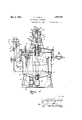
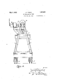
A further object of the invention is to provide a pressure distribution system of the wherein is shown the preferred, but obviously not necessarily, the only form of embodiment of the invention, Fig. 1 is a vertical sectional view of a mixing tank having agitating means therein and a driving mechanism detachably engageable with the agitating mechanism of thetank embodying the present invention. Fig. 2'is a general view somewhat diagrammatic illustrating the system in which the pressure mixing tank illustrated in Fig. 1 is employed. Fig. 3 is a side elevation of a battery of mixing tanks illOllIltGfllIl a supporting structure, having common driving means for the several tanks and a common air supply conduit communicating therewith. Fig. l is an end elevation of the assembly of pressure mixing tanks and a portable mounting structure therefor.
Like parts are indicated by similar characters of reference throughout the several views.
Referring to Fig. 1 of the drawings, 1 is a tank capable of resisting moderately high pressures'having a removable cover section 2 which is securedto the tank 1 in any suitable manner asby means of clamp bolts 3 located at peripherally spaced intervals. Centrally disposed within the tank 1 is a vertical revoluble shaft 3 mounted in ball .bearings 4 within an inwardly extending hub 5 of the COVer portion 2. At its lower end the shaft 3 is journalled in a bronze bearing collar 6,
. screw threaded into an upstanding nipple 7 formed integral with the bottom of the tank 1 which nipple7 also providesa drain outlet, being provided with lateral openings '8 for this purpose. Carried by the revoluble shaft 8 are agitating stirring blades or arms 9 which may be ofany suitable shape and any desired number in accordance with the character of material operated upon. In the present instance a scraping blade has been shown mounted upon the shaft 3 contiguous to the bottom of the tank 1 and an additional stirring arm at a higher level. Obviously, these elements may be increased in number and disposed at various levels. Within the hub 5 there are formed packing glands'l0- and 11 to prevent the escape of air under pressure from the tank and the escape of vapors. The tank is provided with an air supply conduit leading thereto, through which air is admitted under pressure above the liquid level of the contents of the tank. Under the usual conditions of operation air is supplied to the system under an initial pressure of approximately eighty-five pounds per square inch, which by means of a pressure reducing valve is reduced to approximately thirty to fifty pounds per square inch for admission to the tank 1. The air supply conduit 12 leading to the tank is preferably, though not necessarily, provided with a pressure gage 13 by which the tank pressure may be ascertained and proper adjustment maintained for the required pressure. Air admitted to the tank 1 under pressure displaces the liquid contents of the tank, which are intermixed and maintained in a state of agitation, whereby the heavy particles are maintained in suspension, through outlets or distributing conduits 14 the inner ends 15 of which extend downwardly contiguous to the sidewalls of the tank 1 and to approximate relation with the bottom of such tank. These distribution conduit extensions 15 are disposed out of the path of rotation of the agitator arms 9. Located at one side of the tank 1 is a filling hopper 16 through which material may be introduced into the tank. This hopper 16 is connected through an inlet valve 17 with the interior of the tank. During normal operation the valve 17 is maintained closed and is opened only when additional material is to be admitted from the hopper 16 to the tank 1. A series of test conduits 18 are provided leading from the tank 1 at different levels. There may be any number of such test conduits, all of which discharge into the filling hopper 16. These conduits 18 are provided with individual cutoff valves 19. By successively opening cutoff valves 19 of different test conduits 18 to ascertain whether a liquid mixture will be discharged or only air from above the liquid level, the
level of the contents of the tank may be approximately ascertained. All liquid discharged through these test conduits 18 in ascertaining the level of the contents of the tank is returned from the hopper 16 through the inlet valve 17 to the tank. When it is desired to cleanse the tank the remaining contents, and subsequently the cleansing liquid may be withdrawn through the drain outlets 8 in the nipple 7 which nipple is connected with a valved drain outlet20. One or more tanks as described may be mounted either permanently or removably in a frame structure carrying the driving mechanism for the agitating apparatus. In the present construction there is shown a frame comprising upwardly inclined struts 21 interconnected at their lower ends by a transverse angle bar 22 and at their upper end by, a "transverse bar 23w-hich in turn supports longitudinally disposed spaced beams .24. Upon these beams 24 are mounted bearingblocks 25 for a longitudinally disposed drive shaft 26.
The main drive shaft 26 carries at spacedin tervals gear pinions 27,-each of whichv meshes with a beveled gear 28 upon a vertically disposed shaft 29 mounted in suitable bearings 30 supported upon the frame structure. .Slidin-gly adjustable upon the lower end of each dependent stub shaft 29 is a sliding clutch sleeve 31 which may be raisedand lowered by means of a shift lever 32. The upper end of the main shaft3 of the mixing apparatus is provided with a polygonal extremity agreeing with a like opening in the sliding clutch cellar 31. The tank 1 is positioned with its mixer shaft 3 in axial alignment with the dependent stub shaft 29 ofthe driving apparatus. The-slidingclutch collar .31 is lowered by the shift lever 32 and operatively connects the driven stub shaft 29 of the driving mechanism with the polygonal extremity of the mixer shaft 3, thereby driving themixing apparatus.
As before mentioned, the tanks 1 may be either permanently or removably mounted in relation with the driving apparatus frame. In Fig. 3 there isshown a series of removable mixer tanks 1 provided with mixer apparatus of the character before described. In
this casethe discharge conduits 14 preferably lead from the cover sections 2 of the tanks and the air inlet connections 12 of the tanks are connected by detachable couplings 33 with flexible hose conduits 34 communicating with the main vair supply line 35. The air is admitted to the supply conduit 35 under high pressure and is reduced at the reducing valve 36 .to the normal tank pressure. Each branch conduit 34 is provided with a cutoff valve 37. In lieu of providing each tank with a pressure gage as illustrated in Fig. 1, a gage 38 and relief valve 39 may be connected with the air supply conduits 3 5, whereby they will be common to allof the mixer tanks of the series. An air motor-39 mounted upon one end of the framestructure is preferably employed to drivethe main shaft 26. Inasmuch as paint, lacquers and varnishes are highly inflammable and frequently give off explosive vapors, such air motor is much preferred to an electric motor for driving the tnainshaft 26 and thereby the several mixing apparatus. Guide flanges 40 upon the base of the frame structure serve to properly position the several tanks 1 with the upper ends of their drive shafts 3 in axial alignment 'vith the dependent stub shafts 29. By lowering the sliding clutch sleeve 31 the mixer shaft may be connected with the driving mechanism at will. The assembly of interchangeable tanks 1 is shown in end elevation in Fig. 4 in which View the supporting structure for the driving mechanism is also shown mounted upon rollers 41, and the enthe structure may be rendered portable In Fig. 2 the system in which the pressure .mixer is employed has been illustrated somewhat diagrammatically. As a protection again-st fire or explosion the mixer unit has been located in a compartment separated by fire wall43 from the spray booth 44 in which the paint, lacquers, varnish, or other liquid is applied. In this installation the high pressure air conduit 35 communicates through the branch conduit 12 having therein a strainer-and water separator 45 and air reducingvalve 4.6 with the mixer tank 1. Conti-nuing beyond the branch conduit 12 leadmg to the tank .1 the. high: pressure air con- -duit 35 leads to thespray booth .43 whereit connects to the branch conduit 47 and hose connection 48 with the jet nozzle of the air brushorspnayer head 49. A valve 50 con trols the discharge -;of air from the supply conduit 35 through the hose connection -48 to the sprayer head 49.
The discharge conduit 14 leads from the i it to be "discharged through theconduit 1-4 to the sprayer head 49 Where it is subjected to the air jets under higher pressure from the supply conduit 35 causing thematerial to be blown in a spray upon the surface to be coated.- To providefor cleansing the distribution conduit 14 to prevent accumulation of a'deposit of paint, lacquer, varnish or the like, and to remove the contents of the. condu-it the event that the material of-a different character or different color is to be employed, means is provided for washing out the discharge conduit with a solvent,"-thinni-ng solution orcleanser. To this end the ex. t-remity of the liquid distribution conduit 14 and'the hi gh pressure air .conduit35 are inter connected through cont-rolvalves :53 and 54,- and an intermediate flexible hose connection 55. In lieu of this hose connection the pipes may be directly coupled together at their extremities with an interposedcutoff valve. Leading from the branch conduit 1-2 of the air supply system is aconduit 56 havingtherein a. normally closed valve :57; The conduit 56 leads to a --container :58 into which may be introduced through funnel 559 a quantity of liquid-solvent, thinner or cleansing solution. This container 158 is connected through the conduit 59-with thehigh pressure air conduit 35 leading to the spray booth. WVh'en it is-desired to cleanse the system a cut-off valve 60 in the high pressure air conduit 35 intermediate the branch conduit 12 andthe conduit 59 .is closed as :is also a cutoff valve 61 in the branch conduit 12. At the same time the valve 57 in the conduit 56 is opened.
This admits air under pressure from the conduit through the initial portion of the branch conduit 12 and conduit 56 to the con tainer 58 into which has been previously 1ntroduced a quantity of solvent, thinner, or cleansing solution. This air pressure admitted to the container 58 forces the solvent or cleanser solution through the conduit 59 back to the air supply conduit 35 beyond the cutoff valve 60. In other Words, the closing of the valves 60 and 61 and opening of valves 57 and 62 in the conduits 56' and 59 merely bypasses the high pressure air supply through the receptacle 58 and forcing therefrom through the conduit 59 and continuation of the high pressure air conduit 35 the quantity of solvent or cleansing liquid. Such.
quantity of this liquid as maybe necessary to cleanse the sprayer head 49 may be discharged understood that during this cleansing opera-- tion the tank is relieved of internal pressure by opening the filling valve 17. The thinner material or solvent may be utilized during subsequent operation for intermixture with additional supplies of material introduced into the tank 1. f
WVhile the pressure mixer apparatus has been described primarily to its application of spraying paints, lacquers, varnishes and the like, such tank may be mountedupon a vehicle for spraying roadways with dust laying solution or forapplying marking lines to road surfaces. Likewise it may be utilized for spraying disinfectants and for spraying insecticide solution upon trees and shrubbery. The uses mentioned are merely suggestive of the wide range of applications of the invention in one or another of its several forms of embodiment.
From the above description it will be apparent that there is thus provided a construction of the character described, possessing the particular features of advantage be fore enumerated as desirable, but which obviously is susceptible of modification in its form, proportions and arrangement of parts, without departing "from the principle involved or sacrificing any of its advantages; While in order to comply with the statute the invention is described in language more or less specific as to structural features, it is to be understood that the invention is not limited to the specific details shown, but that the means and construction herein disclosed comprise the preferred form of several modes of putting the invention into effect, and the invention is therefore claimed in any of its forms or modifications within the legitimate and'valid scope of the appended claims.
Having thus described my invention, I claim:
1. The herein described system of mixing and distribution of liquids, including a pressure tank, agitator means therein, driving means for the agitator, a sprayer head for the agitated liquid, a high pressure fluid conduit leading to the sprayer head, a branch conduit from said high pressure conduit leading to the pressure tank, a pressure reducer in said branch conduit, a discharge conduit from the tank leading to the sprayer head, a valved bypass conduit communicating atits ends with the high pressure conduit, a cutoff valve in the high pressure conduit between the connections of said bypass conduit, a receptacle for said bypass conduit for the introduction of a cleansing agent, and a valved bypass connection between the high pressure conduit and the discharge conduit adjacent to the sprayer head, the arrangement being such that normally fluid under pressure is delivered to the sprayer head while a portion of the fluid under reduced pressure is delivered to the tank and induces simultaneous delivery to the sprayer head through the discharge conduit of the liquid contents of the tank, and subsequently upon adjustment of the several valves a quantity of cleansing agent is delivered under fluid pressure from the introduction receptacle through the high pressure conduit to the by pass connection with the discharge conduit and thence in reverse direction through the discharge conduit to the tank.
2. In an apparatus of the character described, a tank, a filling hopper communicating therewith, a series of test conduits leading from the tank at different levels and discharging into said filling hopper, valve means by which the conduits may be successively opened, valved connections between the hopper and tank, and means for inducing a flow of the contents of the tank through such conduits into the hopper.
8. In an apparatus of the character described, a pressure tank, a filling compartment communicating therewith, a test conduit leading from the tank at a given level and discharging into the filling compartment, a valve controlling said conduit, and a conduit for admitting fluid under pressure to said tank to induce a flow through said COIl-I duit by-which it may be determined whether. the liquid level is above or below the level of the conduit connection with the tank, the
discharged liquid being returned to the tank through the filling compartment.
4. In an apparatus of the character described, a pressure tank, a filling confpartment therefor, a series of conduits leading from the tank at diflerent levels and discharging into said filling compartment and means for inducing a circuitous flow of liquid from the tank through one or another of said conduits and back to the tank whereby the approximate liquid level of thecontents of the tank may be ascertained.
In testimony whereof, I have hereunto set my hand this 17th da of April, A. D. 1928.
J SEPH F. GOETZ.
Priority Applications (1)
| Application Number | Priority Date | Filing Date | Title |
|---|---|---|---|
| US281306A US1857084A (en) | 1928-05-28 | 1928-05-28 | Air pressure dispenser |
Applications Claiming Priority (1)
| Application Number | Priority Date | Filing Date | Title |
|---|---|---|---|
| US281306A US1857084A (en) | 1928-05-28 | 1928-05-28 | Air pressure dispenser |
Publications (1)
| Publication Number | Publication Date |
|---|---|
| US1857084A true US1857084A (en) | 1932-05-03 |
Family
ID=23076741
Family Applications (1)
| Application Number | Title | Priority Date | Filing Date |
|---|---|---|---|
| US281306A Expired - Lifetime US1857084A (en) | 1928-05-28 | 1928-05-28 | Air pressure dispenser |
Country Status (1)
| Country | Link |
|---|---|
| US (1) | US1857084A (en) |
Cited By (6)
| Publication number | Priority date | Publication date | Assignee | Title |
|---|---|---|---|---|
| US2858116A (en) * | 1955-07-12 | 1958-10-28 | Hale Loren | Mixing and dispersing apparatus |
| US3145930A (en) * | 1961-01-05 | 1964-08-25 | Metallgesellschaft Ag | Electrostatic paint spraying apparatus for changing liquids |
| US3404839A (en) * | 1966-12-05 | 1968-10-08 | Valspar Corp | Mobile paint making and spraying apparatus |
| EP0059380A2 (en) * | 1981-03-04 | 1982-09-08 | Hutter, Charles George, III | System for dispensing curable compositions |
| US5064098A (en) * | 1990-02-23 | 1991-11-12 | Physical Systems, Inc. | Dual component dispenser gun |
| FR2822725A1 (en) * | 2001-03-30 | 2002-10-04 | Jean Marie Droniou | INSTALLATION FOR THE STORAGE AND APPLICATION OF COATINGS |
-
1928
- 1928-05-28 US US281306A patent/US1857084A/en not_active Expired - Lifetime
Cited By (10)
| Publication number | Priority date | Publication date | Assignee | Title |
|---|---|---|---|---|
| US2858116A (en) * | 1955-07-12 | 1958-10-28 | Hale Loren | Mixing and dispersing apparatus |
| US3145930A (en) * | 1961-01-05 | 1964-08-25 | Metallgesellschaft Ag | Electrostatic paint spraying apparatus for changing liquids |
| US3404839A (en) * | 1966-12-05 | 1968-10-08 | Valspar Corp | Mobile paint making and spraying apparatus |
| EP0059380A2 (en) * | 1981-03-04 | 1982-09-08 | Hutter, Charles George, III | System for dispensing curable compositions |
| WO1982003023A1 (en) * | 1981-03-04 | 1982-09-16 | Charles George Hutter Iii | System for dispensing curable compositions |
| US4407431A (en) * | 1981-03-04 | 1983-10-04 | Hutter Iii Charles G | System for dispensing curable compositions |
| EP0059380A3 (en) * | 1981-03-04 | 1984-07-18 | Charles George Hutter, Iii | System for dispensing curable compositions |
| US5064098A (en) * | 1990-02-23 | 1991-11-12 | Physical Systems, Inc. | Dual component dispenser gun |
| FR2822725A1 (en) * | 2001-03-30 | 2002-10-04 | Jean Marie Droniou | INSTALLATION FOR THE STORAGE AND APPLICATION OF COATINGS |
| WO2002078856A1 (en) * | 2001-03-30 | 2002-10-10 | Jean-Marie Droniou | Installation for storage and application of coating products |
Similar Documents
| Publication | Publication Date | Title |
|---|---|---|
| US2504009A (en) | Agitating and dispensing unit | |
| US2022481A (en) | Circulating and mixing system | |
| US4358054A (en) | Field-sprayer tank-vehicle having means for on-site metering and mixing of soil-treating chemicals | |
| US1733724A (en) | Tank and agitating construction for paint-spraying apparatus | |
| US3881656A (en) | Mixing apparatus | |
| US1857084A (en) | Air pressure dispenser | |
| US3134549A (en) | Dispersing apparatus | |
| US6550692B1 (en) | Self-contained finish spraying apparatus | |
| US2846123A (en) | Liquid handling apparatus for delivering paints and other liquid materials to spray guns | |
| US1254429A (en) | Automatic painting apparatus. | |
| US1971535A (en) | Apparatus for coating pipe | |
| CN217119981U (en) | Paint mixing of colors device | |
| US1647473A (en) | Device for supplying cleaning solution | |
| US2552763A (en) | Apparatus for handling and applying plaster | |
| US2270628A (en) | Concrete mixer | |
| US1600948A (en) | Apparatus for producing bituminous compositions with water | |
| US1725581A (en) | Tank distributor | |
| US2660415A (en) | hawes | |
| US3281123A (en) | Proportioning and mixing device | |
| US2608393A (en) | Apparatus for mixing or agitating coating and granular materials | |
| US1947994A (en) | Apparatus for handling soaps | |
| CN212632536U (en) | Premix formula coating agitating unit | |
| US1691535A (en) | Apparatus for mixing dry and liquid materials | |
| US2687331A (en) | Projecting apparatus | |
| US1355190A (en) | Process for mixing viscous materials |