US1857734A - Sugar dispensing container - Google Patents
Sugar dispensing container Download PDFInfo
- Publication number
- US1857734A US1857734A US505864A US50586430A US1857734A US 1857734 A US1857734 A US 1857734A US 505864 A US505864 A US 505864A US 50586430 A US50586430 A US 50586430A US 1857734 A US1857734 A US 1857734A
- Authority
- US
- United States
- Prior art keywords
- sugar
- receptacle
- valve
- wall
- block
- Prior art date
- Legal status (The legal status is an assumption and is not a legal conclusion. Google has not performed a legal analysis and makes no representation as to the accuracy of the status listed.)
- Expired - Lifetime
Links
Images

Classifications
-
- A—HUMAN NECESSITIES
- A47—FURNITURE; DOMESTIC ARTICLES OR APPLIANCES; COFFEE MILLS; SPICE MILLS; SUCTION CLEANERS IN GENERAL
- A47G—HOUSEHOLD OR TABLE EQUIPMENT
- A47G19/00—Table service
- A47G19/30—Other containers or devices used as table equipment
- A47G19/32—Food containers with dispensing devices for bread, rolls, sugar, or the like; Food containers with movable covers
- A47G19/34—Food containers with dispensing devices for bread, rolls, sugar, or the like; Food containers with movable covers dispensing a certain quantity of powdered or granulated foodstuffs, e.g. sugar
-
- G—PHYSICS
- G01—MEASURING; TESTING
- G01F—MEASURING VOLUME, VOLUME FLOW, MASS FLOW OR LIQUID LEVEL; METERING BY VOLUME
- G01F11/00—Apparatus requiring external operation adapted at each repeated and identical operation to measure and separate a predetermined volume of fluid or fluent solid material from a supply or container, without regard to weight, and to deliver it
- G01F11/28—Apparatus requiring external operation adapted at each repeated and identical operation to measure and separate a predetermined volume of fluid or fluent solid material from a supply or container, without regard to weight, and to deliver it with stationary measuring chambers having constant volume during measurement
- G01F11/36—Apparatus requiring external operation adapted at each repeated and identical operation to measure and separate a predetermined volume of fluid or fluent solid material from a supply or container, without regard to weight, and to deliver it with stationary measuring chambers having constant volume during measurement with supply or discharge valves of the rectilinearly-moved slide type
- G01F11/40—Apparatus requiring external operation adapted at each repeated and identical operation to measure and separate a predetermined volume of fluid or fluent solid material from a supply or container, without regard to weight, and to deliver it with stationary measuring chambers having constant volume during measurement with supply or discharge valves of the rectilinearly-moved slide type for fluent solid material
Definitions
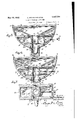
- Figure 1 is a top plan view of a sugar dis pensing container constructed in accordance with the present invention vand showinghinged cover sectlons at the upper side of the container to facilitate the charging of the latter with sugar,
- Figure 2 is a front elevational view of the container showing the push rod for operat ing the interior mechanism controlling the dispensing of sugar, and the discharge spout;
- Figure 3 is a side elevational view
- Figure 4 is an enlarged vertical cross-sec tional view taken on line 4:& of Figure 2 showing the push rod operated valve plate for measuring and controlling'the dispensing of sugar, the upper hopperand the lower discharge chute;
- Figure 5 is a verticallongitudinal sectional view, taken on line 5-5 of Figure 1, showing the tensioned valve plate separating the hopper from the discharge chute and the push rod attachment for the valve plate;
- Figure 6 is a sectional View, similar to Figure 5, showing the valve plates in shifted position against the, tension of the springs engaged therewith for the dispensing of a predeterminedquantity of sugar; 7
- Figure 7 is a horizontal sectional view taken on line 7-7 of Figure 6;
- FIG 8 is a fragmentary perspective View [of the sugardispensing-valve plate. 1
- a sugar dispensing container designed for ⁇ dis- 5 pensing predetermined quantities of sugar at each operation thereof, the container com ⁇ prising a; supporting base 10 provided with a.
- the interior construction of the receptacle 12 includes spaced'partitions 20 and 21 as shown in- Figures 5 and-6 and a central block 22 having ameasuring'pocket 23 therein that is in communication with theuppe'r part'of the receptacle 12 andin to which sugariis directed by the inclined walls 24 disposed-above the partition 20.
- Thevalve'device includes i an endlwall 27 that has projecting from one (side thereof at its u er and lower "edges,
- the partition 20 is provided with a groove 28a to receive the valve plate 28 while the partition 21 is provided with a groove 29a to receive the valve plate 29.
- the end wall 27 of thevalve device carries an operating-push rod throughthe coverwall25 and having an op.-
- a block forming an integral part of the receptacle and in which the opening is formed, said block having spaced grooves extending laterally of the block opening at one side and closed at their outer ends, a reciprocating valve device having spaced apertured plates and an end connecting Wall with the wall normally engaged with the block when the valve device is in closed position to prevent flow of material from the receptacle into the block opening, said "apertured plates being slidable in the block grooves, springs interposed between a wall of the receptacle and the outer side of the connecting wall of the valve device for urging the valve device to closed position and in operating pull rod for the valve device attached to the end connecting wall and extending through a wall of the receptacle and movable with the valve device in the direction of movement thereof.
- the provision of the grooves 28a-and 29a in the block partitions '20 and 21 provides a substantial support and guide for the valve device while one side of the block 22 provides movement limiting means for the valve device.
- the springs 34 effect retracting of the valve when pressure on the push rod32-is relieved.
- a re- 'ceptacle having abottom opening, a basesupport for the receptacle, a laterally directed spout'carried by the base support in com- GEORGE MOLDOVAN.
Description
y 1932. G. MOLDOVAN ET AL 1,3573% SUGAR DISPENSING CONTAINER Fi led Dec. 51, 1930 2 Sheets-Sheet 1 6207" 6 fiiZ/dOz/dh & 6Z6 5 2767726572 Patented May 10, 1932 UNITED STATES ,PATET 'VQ FFICE, a
GEORGE MOLDOVAN, F MEADOW LANDS, AND STEVE NEMETH PENNSYLVANIA Y V i ,on wesrimeron,
SUGAR DISPENSING conrernnn Application filed December 31, 1930, Iseriai No. 505,864. j
'termined quantity of sugar, such as a tea spoon full is dispensed at each operation of the device, the container being so designed that a cup or other receptacle may be positioned relative to the container to receiv the discharged sugar. I
With the above and other objects in View that will become apparent asth e nature of the invention is better understood, the same consists in the novel form, combination and arrangement of parts hereinafter more fully described, shown in the accompanying drawings and claimed.
In the drawings v Figure 1 is a top plan view of a sugar dis pensing container constructed in accordance with the present invention vand showinghinged cover sectlons at the upper side of the container to facilitate the charging of the latter with sugar,
Figure 2 is a front elevational view of the container showing the push rod for operat ing the interior mechanism controlling the dispensing of sugar, and the discharge spout;
Figure 3 is a side elevational view;
Figure 4 is an enlarged vertical cross-sec tional view taken on line 4:& of Figure 2 showing the push rod operated valve plate for measuring and controlling'the dispensing of sugar, the upper hopperand the lower discharge chute;
Figure 5 is a verticallongitudinal sectional view, taken on line 5-5 of Figure 1, showing the tensioned valve plate separating the hopper from the discharge chute and the push rod attachment for the valve plate;
Figure 6 is a sectional View, similar to Figure 5, showing the valve plates in shifted position against the, tension of the springs engaged therewith for the dispensing of a predeterminedquantity of sugar; 7
Figure 7 is a horizontal sectional view taken on line 7-7 of Figure 6; and
Figure 8 is a fragmentary perspective View [of the sugardispensing-valve plate. 1 Referring more in detail to the accompanylng drawings, there'is illustrated a sugar dispensing container designed for} dis- 5 pensing predetermined quantities of sugar at each operation thereof, the container com} prising a; supporting base 10 provided with a. seat .at its" upper end formed by front and rear upstanding flanges 11 and between 6' which'fiang'es the sugarr'eceptacle 12 is received, the, receptacle 12 comprising parallel sidewalls 13, acurved bottom wall 14 and a flattop wall comprising a center bridge 0 strip '15 midwaythe'endsof the receptacle an'd to which doors16 arehinged as at-117, the outer'free endsof the doorslG being retained in closed position-by spring clips '18. The'receptaclel l is retainedin position upon v the supporting baselO by anchoring screws 19 "as shown injFigure. 4 a
The interior construction of the receptacle 12 includes spaced'partitions 20 and 21 as shown in-Figures 5 and-6 and a central block 22 having ameasuring'pocket 23 therein that is in communication with theuppe'r part'of the receptacle 12 andin to which sugariis directed by the inclined walls 24 disposed-above the partition 20.
One side portion ofthe curved bottom r of the receptacle is provided with an opening that is closed by the cover wall 25 retained r in position by the screws 26 to facilitate positioning ofthe valve device shown'in Figure 8 in the receptacle, Thevalve'device includes i an endlwall 27 that has projecting from one (side thereof at its u er and lower "edges,
erating handle, 33 upon its outer end while coil springs 34 are anchored to attends to F the-cover wall 25 andjend ,wall 27, of the valve municates with the spout 36.
c 7 From the above detailed description, it is believed that the construction and operation of the sugar dispensing container will at once be understood, it being noted that the forward side of the base 10 is provided with an incut portion 10a topermit the positioning of the cup or the like in position to receive the sugar to be discharged from the chute 36. Sugar or similar fluent material is placed in-the receptacle 12 when the cover or walls '16 are open and the inclined partitions 24 direct the discharge of sugar into the pockets 23, the normal positions of the valve plates 28 and 29 being illustrated in Figure 5, wherein the valve device is illustrated as retracted by the springs 34. Upon operating the push rod '32 the plates '28 and 29 are moved into the grooves 28a and 29a respectively of the munication with the receptacle opening, a block forming an integral part of the receptacle and in which the opening is formed, said block having spaced grooves extending laterally of the block opening at one side and closed at their outer ends, a reciprocating valve device having spaced apertured plates and an end connecting Wall with the wall normally engaged with the block when the valve device is in closed position to prevent flow of material from the receptacle into the block opening, said "apertured plates being slidable in the block grooves, springs interposed between a wall of the receptacle and the outer side of the connecting wall of the valve device for urging the valve device to closed position and in operating pull rod for the valve device attached to the end connecting wall and extending through a wall of the receptacle and movable with the valve device in the direction of movement thereof.
In testimony whereof we affix our signatures.
STEVE NEMETH.
WVhile there is herein shown and described the preferred embodiment of the invention,
;it is nevertheless to be understood that minor 7 changes maybe made therein without departing fromthe spirit and scope of the invention as claimed. 7 I i We claim:
*In a measuring and dispensing device, a re- 'ceptacle having abottom opening, a basesupport for the receptacle, a laterally directed spout'carried by the base support in com- GEORGE MOLDOVAN.
Priority Applications (1)
| Application Number | Priority Date | Filing Date | Title |
|---|---|---|---|
| US505864A US1857734A (en) | 1930-12-31 | 1930-12-31 | Sugar dispensing container |
Applications Claiming Priority (1)
| Application Number | Priority Date | Filing Date | Title |
|---|---|---|---|
| US505864A US1857734A (en) | 1930-12-31 | 1930-12-31 | Sugar dispensing container |
Publications (1)
| Publication Number | Publication Date |
|---|---|
| US1857734A true US1857734A (en) | 1932-05-10 |
Family
ID=24012187
Family Applications (1)
| Application Number | Title | Priority Date | Filing Date |
|---|---|---|---|
| US505864A Expired - Lifetime US1857734A (en) | 1930-12-31 | 1930-12-31 | Sugar dispensing container |
Country Status (1)
| Country | Link |
|---|---|
| US (1) | US1857734A (en) |
Cited By (6)
| Publication number | Priority date | Publication date | Assignee | Title |
|---|---|---|---|---|
| US2445501A (en) * | 1945-03-28 | 1948-07-20 | Edward J Vagim | Hopper assembly with solenoid operated gate |
| US3092292A (en) * | 1960-10-03 | 1963-06-04 | Dorothy Jane Mahaffey Carpente | Instant coffee and tea dispensing machine |
| US4993593A (en) * | 1989-07-21 | 1991-02-19 | Ralph Fabiano | Apparatus and methods for dispensing a flowable medium |
| US5339994A (en) * | 1991-02-25 | 1994-08-23 | Nuila Jorge A | Fertilizer or like dry material dispensing assembly |
| US5746355A (en) * | 1996-03-15 | 1998-05-05 | Cargill, Incorporated | Dispenser for pulverulent material |
| US5944231A (en) * | 1991-02-25 | 1999-08-31 | Nuila; Jorge Arturo | Fertilizer or like dry material dispensing assembly and dispensing gun therefor |
-
1930
- 1930-12-31 US US505864A patent/US1857734A/en not_active Expired - Lifetime
Cited By (6)
| Publication number | Priority date | Publication date | Assignee | Title |
|---|---|---|---|---|
| US2445501A (en) * | 1945-03-28 | 1948-07-20 | Edward J Vagim | Hopper assembly with solenoid operated gate |
| US3092292A (en) * | 1960-10-03 | 1963-06-04 | Dorothy Jane Mahaffey Carpente | Instant coffee and tea dispensing machine |
| US4993593A (en) * | 1989-07-21 | 1991-02-19 | Ralph Fabiano | Apparatus and methods for dispensing a flowable medium |
| US5339994A (en) * | 1991-02-25 | 1994-08-23 | Nuila Jorge A | Fertilizer or like dry material dispensing assembly |
| US5944231A (en) * | 1991-02-25 | 1999-08-31 | Nuila; Jorge Arturo | Fertilizer or like dry material dispensing assembly and dispensing gun therefor |
| US5746355A (en) * | 1996-03-15 | 1998-05-05 | Cargill, Incorporated | Dispenser for pulverulent material |
Similar Documents
| Publication | Publication Date | Title |
|---|---|---|
| US4531658A (en) | Measured charge dispenser, particularly for powdered material | |
| US3023937A (en) | Measuring dispenser | |
| US2029460A (en) | Drink vending machine | |
| US1687705A (en) | Dispensing device | |
| US1857734A (en) | Sugar dispensing container | |
| US1869120A (en) | Dispensing device | |
| US2123606A (en) | Dispensing device | |
| US1980057A (en) | Dispensing apparatus | |
| US2775270A (en) | Dispensing apparatus | |
| US1752527A (en) | Measuring device | |
| US2245066A (en) | bouchard | |
| US2729376A (en) | Beverage vending machine | |
| US470018A (en) | John n | |
| US1798095A (en) | Self-serving beverage fountain | |
| US2436075A (en) | Dispensing pillbox | |
| US2114246A (en) | Coin-controlled bottle dispenser | |
| US1337440A (en) | Dispensing device for nut-meats | |
| US3834593A (en) | Adjustable granular material dispenser | |
| US1957326A (en) | Dispensing device | |
| US2318676A (en) | Dispensing device | |
| US2745577A (en) | Combination shaker and spout device for salt shakers | |
| US2028655A (en) | Fluent material dispensing device | |
| US4277002A (en) | Ice dispensing mechanism | |
| US448275A (en) | Soap holder and distributer | |
| US1363828A (en) | Coin-delivering device |