US1908412A - Testing machine - Google Patents
Testing machine Download PDFInfo
- Publication number
- US1908412A US1908412A US518618A US51861831A US1908412A US 1908412 A US1908412 A US 1908412A US 518618 A US518618 A US 518618A US 51861831 A US51861831 A US 51861831A US 1908412 A US1908412 A US 1908412A
- Authority
- US
- United States
- Prior art keywords
- specimen
- spring
- force
- casing
- deflection
- Prior art date
- Legal status (The legal status is an assumption and is not a legal conclusion. Google has not performed a legal analysis and makes no representation as to the accuracy of the status listed.)
- Expired - Lifetime
Links
Images


Classifications
-
- G—PHYSICS
- G01—MEASURING; TESTING
- G01N—INVESTIGATING OR ANALYSING MATERIALS BY DETERMINING THEIR CHEMICAL OR PHYSICAL PROPERTIES
- G01N3/00—Investigating strength properties of solid materials by application of mechanical stress
- G01N3/08—Investigating strength properties of solid materials by application of mechanical stress by applying steady tensile or compressive forces
Definitions
- This invention relates to testing machines and it has particular relation to machines for testing objects that are to be'subjected to applied to an object being tested, and the deflection producedthereby, without. compensating for the weight of the object or any part of the machine.
- means are provided for actuating an indicatorjn response to the deflection of a resilient member .upon the application of force to an object to be tested, and for simultaneously actuating a second indicator that is responsive to the deflection of the object;
- this includes a resilient member connecting two relatively movable members, one of which engages the object to be tested, and means for moving the members to apply force to the object so that the relative motion of the members against the restraining force of the resilient member actuates the force indicator operating mechanism; and it also includes operating mechanism for the deflection indicator that is actuated by movement of the member which engages the object.
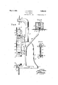
- Figure 1 is a view, partially in elevation and partially in section, of a testing machine constituting one embodiment of this inventlon.
- Fig.2 is a view, partially in elevation and partially in section, of a testing machine of
- Fig. 5 is a sectional view taken on the line 5.-5 of Fig. 1.
- FIG. 6 is a side elevational view of the testing machine of Fig. 1.
- Fig.- 7 is a view showing an alternate method and means for holding objects to be tested.
- Fig. 8 is a diagrammatic view showing the principle of operation of the deflection indicator.
- the testing ma chine comprises a frame member 10 consisting of a base plate 11; a vertically extending web member 12, which changes its configuration near the top to form a shoulder member 13 and lateral extensions 14 and 15, having a circular opening 16 extending therethrough.
- a post 17 mounted on top of the frame 10, is threadedly aflixed thereto and extends upwardly, changing its direction and configuration near the top to form a flat'bar 18 that is substantially horizontal.
- the rack consists of a plurality of teeth cut in the bar 19, and the pinion is formed by cutting teeth on the end of a shaft 23, that extends through the openings 16 in the lateral extensions 14 and 15.
- the shaft 23 is increased in diameter at one end toform a collar 24 that abuts against the end of the lateral extension 14, and the shaft is held in the lateral extensions, free to rotate, by means of a screw 25, that extends through a plate 26 and the end of the shaft 23, the plate 26 abutting against the end of the lateral extension 15.
- the shaft 23 is rotated by means of a lever arm 27 afiixed to the endtthereof.
- An open face casing or housing 28 is carried by the bar 19 and is attached thereto by means of bolts 29, that extend through the bar near the opposite ends thereof and into interiorly threaded arms 30, disposed at the top and bottom of the casing 28, formed integrally therewith and extending laterally from the rear thereof, the ends of itzge arms 30 being in abutting relation to the extending longitudinally
- a movable runner or rod 31 extends longitudinally through the casing 28, extendin through openings 32 and'33 1n the top and bottom walls, respectivel and into a second casing or housing 34 t rough an opening 35, the casing 34 being above the casing 28.
- the rod 31 carries the casing 34 by being aflixed to the rear wall thereof by means of screws 36.
- the .rod 31 is supported by a spring 37 that is disposed around it and suspended from the top wall of the casing 28 by means of a plate 38, surrounding the rod and attached to the casing by means of screws 39, and provided with downwardly extending members 41 having flanges 42 projecting outwardly therefrom.
- the upper turns of the spring are disposed against the members 41 between the plate 38 and the flanges 42, and the lower end of the spring extends through an opening in the rod 31 thereby supporting it.
- a sleeve 43 surrounds the rod at the lower end of the casing 28, extending through the opening 33 in the bottom thereof.
- the sleeve 43 is provided with a shoulder 43athat rests on the bottom wall of the casing 28, and is provided with a spiral groove.
- the sleeve is threaded at its lower end to receive a lock nut 44, to lock it in position.
- a spring 45 designated the load spring surrounds the sleeve, the lower-turns of the spring, fitting into the spiral, and the uppermost turn of the spring beingbent to extend through an opening 46 in the rod 31, and resting on a knife edge as at 47.
- the rod 31 and the casin 28 are resiliently connected toether. he tension of the s ring 37 is adjusted until the knife edge 4 is exerting a sli ht force on the spring to prevent back- 1 when force is impressed on the specimen and there is relative motion between the casing and the rod.
- the machine may be calibrated before complete assembly of the machine by turning the spring in the groove thereby varying the tension of the spring.
- Rollers 48 are disposed in slots 49 cut transversely in the rod one above the other and are held by'shafts 50 that extend into openings in the rod 31.
- the sleeve 43 functions as a guide for the rod 31, and the rollers 48 aid in maintainin the rod centrally in the sleeve and re ucing friction gliereby facilitating the movement of the rod
- a self-centering disc 51 having a V-shaped notch 51a (Fig. 1 is attached to the bottom of the rod 31, an cooperates with a second self-centering disc 52 having a Vshaped notch 52a to hold a specimen that is to be given a compression test.
- the discv 52 is held by an adjustable screw 53, that extends through a threaded opening in the base plate 5 11 and is held in a predetermined position by means of a lock nut 54.
- a lever arm 55 is provided to loosen the lock nut 54 to permit the disc 52 .to be. moved, thus varying the distance between the discs, in order to accommodate specimens of different lengths.
- Step chucks may be employed instead of the discs for holding the specimen.
- a hook 56 disposed in the upper extremity of the rod 31, extends through an opening 57 in the casing 34 and cooperates with a similar hook 58, held by the fiat bar 18, to hold a specimen that is to be given an extension test.
- the hook 58 is held in a predetermined position by means of a lock nut 59, and is threadably adjustable in lock nut 59 to vary the distance between hooks, in order to accommodate specimens of different lengths.
- the load spring 45 which connects the casing and rod together. If the specimen be a yieldable one, such as a spring, it changes in length a certain amount upon the application of force due tothe action' of the spring 45. As the impressed force is increased the spring offers a greater resistance to a further change in length than can be completely overcome by the load spring 45 and the casing 28 moves downwardly more than th rod 31, efi'ecting relative motion' between them against the restraining force of the spring 45 and causing distention or elongation of the spring.
- the dial 59 is mounted on the front of the casing 28 and is afiixed thereto by screws 62 that extend into bosses 63 formed integrally with the side walls of the casing.
- the indicator 61 is mounted on a shaft 64 extendin through an opening in the center of the ial 59 and held by two' to t e strap 66 by screws 65a.
- the strap 66 extends across the front of the casing 28 and is attached thereto by screws 67 that extend into bosses 68 formed integrally with the side walls of the casing;
- the indicator is actuated by a rack 69 and a pinion 71, the rack depending from a stud 72 that is affixed' to the rod 31, and the pinion being mounted on the shaft 64.
- the dial 59 is provided with a scale graduated, in pounds, and the elements of the machine are so designed, that the indicator is moved around the dial in exact proportion to equal units of a plied force.
- a load spring designed for two hundred pounds tensile strength, and a scale the indicator will be moved completely around the dial, when the lever arm is moved from the position of zero applied force .to the position of maximum apphed force.
- the amount of deflection is indicated on a dial 74 by an indicator 75.
- the dial 74 is provided with a scale so graduated that the deflection of the specimen may be indicated 'thereon in convenient units.
- the dial 74 is mounted on the front of the upper casing 34 by being at tached to a strap 76 that extends across the front of the casing and is secured thereto by screws 77 which extend intobosses 78' formed integrally with the side dwalls of the casing.
- the indicator is mounted on a shaft 7 9 extending through an opening in the center of the dial 74 and the strap 76 and is sup.- ported by a strap 81 that is secured to the side walls of the casing by means of 'the screws 77.
- the deflection indicator is operated by a sprocket wheel 82 and chain 83, the sprocket wheel being mounted on the shaft'79 between the straps 76 and 81.
- the chain 83 depends from the sprocket wheel 82'through the openin end of the chain being attached at 84 to one end of a stationary S-shap arm 85 that extends through a slot 86 in the rear of the casing and is attached to the shoulder member 13 at 87.
- the other end of the chain 83 is attached to one end of a helical spring 88, the other end of which is attached to an arm 89 that is aflixed to the side wall of the cas ing 28.
- the point 84 is fixed with respect to the rod 31 and the center line of the .sprocket wheel 82.
- the rod 31 moves downwardly the distance between the point 84 and the center line of the sprocket wheel decreases and the chain .83 is pulled over the sprocket wheel by the action of'the spring 88, as illustrated in Fig. 8, therebyactuating the deflection indicator 7 5.
- Fig. 2 illustrates a spring 91 being tested for compression.
- the disc 52 is so a 'usted that the space between the discs'51 an 52 is just sufand 32 in the casings 34 and 28, respectively, into the lower casing 28, one
- the applied force is illustrated as'one hundred pounds, as indicated on the dial 59, causing a deflection of the spring of three tenths of an inch, as indicated on the dial 75.
- Fig. 2 illustrates a sprin being tested for compression, it is obvious t at if a spring be connected to thehooks 56 and 58, and the lever arm27 .moved downwardly,
- FIG. 7 is illustrated an alternate pair of discs 92 and 93 for holding a light spring that isfto be tested.
- the disc 92 is attached to the rod 31 and is provided with a recess 94 large enough to receive circular member 95, that has a projection 96 on the bottom thereof to fit into a recess 97 in the disc 93.
- the spring 98 to be tested is-disposed around the member 95 and upon the -ap- ⁇ plication of force, the spring isprevented from buckling, the member 95 passing into the recess 94 upon the deflection ofthe spring.
- Members 95' of difl'erent diameters are provided for springs of different diameters and difl'erent discs 92 are substituted with recesses 94 large enough to permit the entrance of the member 95 upon the'deflection of the spring 98.
- the diameter of the projection 96 may be the same on all the different size members 95, thus permitting the use of a single lower disc with the diiferent sizes of the members 95.
- a testing machine comprising in combination a member, a second-member relatively movable thereto, means for resiliently supporting said second member from said first member, means for resiliently connecting the two members together, means for holding a specimen to be tested; one of said members being connected to the specimen holding means, means for actuating the mem bers to apply force to the specimen, means for indicatingthe applied force and means for indicating the deflection of the specimen produced by said force.
- a testing machine comprising in combination a member, a second member relatively movable thereto, means for resiliently supporting said second member from said first member, means for resiliently connecting the two members together, means for holding a specimen to be tested, one of said members being connected to the specimen holding means, means for actuating the members to apply force to thespecimen, means for indicating theapplied force and means for indicating the deflection of the specimen produced by said force, and means for preventing buckling of the specime upon theapplication of force.
- a at bination a member, a second member relatively movable thereto, means for resiliently supporting said second member from said first member, resilient means for connecting the two members together, means for holding a specimen to be tested, one of said members being connected to the specimen holding means, means for actuating said members to exert force on the specimen, an indicator responsive to the distention of the resilient means and an indicator responsive .plication of force. ting machine comprising in com-- to the movement of themember connected to the specimen holding means.
- a testing machine comprising in combination a member, a second member, means for resiliently supporting said second member from sald first member, a spring con.- necting the two members together, means for holding a specimen to be tested, the second member being connected to the specimen holding means, means for actuating the two members to exert force on the specimen, means responsive to the relative motion of the two members against the action of the spring for indicating the applied force and means responsive to the movement of the second member for indicating the deflection of the specimen.
- a testing machine comprising in combination a member, a second member, means for resiliently-supporting said second member from said first member, a spring connecting the two members together, means for holding a specimen to be tested, the second member being connected to the specimen holding means, means for actuating the two members to exert force on the specimen, means responsive to the relative motion of the two members against the action of the spring for indicating the applied force,
- a testing machine comprising in combination a member, a second member, means for resiliently supporting said second member from said first member, a spring connecting the two members together, means for holding a specimen to be tested, the second member being connected to the specimen holding means, means for actuating the two members to exert force on the specimen, means responsive to the relative motion of the two members against, the action of the spring for indicating the applied. force, means responsive to the movement of the second member for indicating the deflection of the specimen, means for adjusting the tension of the spring and means for preventing buckling o the specimen upon the ap 7.
- a testing machine comprising in combination a member having an opening, a second member extending through said opening, means for resiliently supporting the second member from the first while permitting relative motion between them, a spring disposed about the second member and connecting the two members together, means connected with the second member for hold ing a specimen to be tested, means for actuating the members to apply force to the specimen, means responsive to the elongation of the spring for indicating the applied force and means responsive to the movement of the second member for indicating the deflection of the specimen.
- a testing machine comprising in combination a stationary member anda movable member adapted to support a test specimen between them, a second movable member, means for resiliently connecting the two movable members together, means for resiliently supporting the first movable member from the second while permitting it to move relatively thereto, means for actuating the movable members to apply force to'the test specimen, means for indicating the applied 'force and means for indicating the deflection of the specimen produced by said force.
- a testing machine comprising incombination a stationary member and a movable member adapted to support a test specimen between them, a housing for said movable member, means for resiliently connecting the housing and the movable member,
- a testing machine comprising in combination two members for supporting a test specimen, a runner connected to one of said members, a housing having an opening, the runner extending through the housing, means for resiliently supporting said runner from said housing, a spring connecting the housing and the runner, means for actuating the housing to apply force to the specimen, means responsive to the deflection of the spring for indicating the force and means for indicating the deflection of the specimen produced by said force.
- a testing machine comprising in combination a casing, a resilient member'connected thereto, a runner connected to the resilient member and means for resiliently supporting the runner from the casing, means cooperating with the runner for supporting a specimen to be tested, means for actuating the casing to exert force on said specimen, indicating means responsive to the elongation of the resilient member, and indicating means responsive to the movement of the runner for indicating the deflection of the specimen.
- a testing machine comprising i1 combination a housing havin an opening, a runner extending through said opening, means for resiliently supporting said runner from said housing, a resilient member having one end connected to the housing and the other end connected to the runner, means cooperatinga with the runner to support a .ner extending through said opening, means specimen to be tested, means for actuating the housing to apply force to the specimen, indicating means responsive to the relative movement of the housing and the runner, and indicating means responsive to the movement of the runner.
- a testing machine comprising in combination a housing having an opening, a runner extending through said opening, means for resiliently supporting said runner from said housing, a spring disposedabout the runner one end of which is connected thereto and the other end being connected to the housing, means cooperating with the runner for holding a specimen to be tested, means for effecting movement of the casing to impress force upon the specimen, indicating means responsive to the elongation of the spring, indicating means responsive to the movement of the runner to indicate the deflection of the specimen and means for adjusting the tension of the spring.
- a testing machine comprising in combination a housing having an opening, 'a runfor resiliently supporting saidrunner from said housing, a spring disposed about the runner one end of which is connected thereto and the other end being connected to the housing, means cooperating with the runner for holding a specimen to be tested, means for eflecting movement of the casing to impress force upon the specimen, indicating means vresponsive to the elongation of the spring, indicating means responsive to the movement. of the runner to indicate the deflection of the specimen and means forpreventing buckling of the specimen upon the application of force.
- a testing machine comprising in combination a spring, a housing having an opening, a runner extending through said opening and suspended from the top thereof by means of said spring, a coil spring surrounding the runner and connected thereto, the I
Description
y 9,1933- J. H. DOMINA 1,908,412.
' TESTING MACHINE Filed Feb. 27, 1931 s Sheets-Sheet 1 INVENTOR JAMES H. DOMINA ATTORNE May 9, I933. J.,H. DOMINA Y 1,908,412
, TESTING MACHINE Filed Feb. 27, 1931 s Sheets- Sheet 2 INVENTOR Jr v BY Y r ATTORNEY JAMES H. DOMINA y 9 J. H. DOMINA: 1,908,412
TESTING MACHINE Filed Feb. 21; 1951 5 Sheets-Sheet 3 6 4 I IHIIII a 'l "I, -1 1/ if Hm. 'HHIII "\hll'. n, [H
7; n INVENTOR :3 JAMES H. DOMINA BY 2 ATTORNEY Patented May 9, 1933 UNITED-STATES PATE T- J OFFICE JAMES H. DOMINA, OF PATERSON, NEW JERSEY, ASSIGNOR' TO JOHN 80118, OF NEW YORK, N. Y., A CORPORATION OF NEW XOR TESTING MACHINE App1ioat1on filed February 27, 1931. Serial in. 518,618.
. This invention relates to testing machines and it has particular relation to machines for testing objects that are to be'subjected to applied to an object being tested, and the deflection producedthereby, without. compensating for the weight of the object or any part of the machine.
According to this invention, means are provided for actuating an indicatorjn response to the deflection of a resilient member .upon the application of force to an object to be tested, and for simultaneously actuating a second indicator that is responsive to the deflection of the object; Specifically, this includes a resilient member connecting two relatively movable members, one of which engages the object to be tested, and means for moving the members to apply force to the object so that the relative motion of the members against the restraining force of the resilient member actuates the force indicator operating mechanism; and it also includes operating mechanism for the deflection indicator that is actuated by movement of the member which engages the object.
The invention will be better understood from the following description, when read in conjunction with the accompanying draw ings, in which;
Figure 1 is a view, partially in elevation and partially in section, of a testing machine constituting one embodiment of this inventlon.
Fig.2 is a view, partially in elevation and partially in section, of a testing machine of,"
Fig. 5 is a sectional view taken on the line 5.-5 of Fig. 1.
'Fig. 6 is a side elevational view of the testing machine of Fig. 1.
Fig.- 7 is a view showing an alternate method and means for holding objects to be tested.
Fig. 8 is a diagrammatic view showing the principle of operation of the deflection indicator.
Referring to the drawings, the testing ma chine comprises a frame member 10 consisting of a base plate 11; a vertically extending web member 12, which changes its configuration near the top to form a shoulder member 13 and lateral extensions 14 and 15, having a circular opening 16 extending therethrough. A post 17 mounted on top of the frame 10, is threadedly aflixed thereto and extends upwardly, changing its direction and configuration near the top to form a flat'bar 18 that is substantially horizontal.
. An open face casing or housing 28 is carried by the bar 19 and is attached thereto by means of bolts 29, that extend through the bar near the opposite ends thereof and into interiorly threaded arms 30, disposed at the top and bottom of the casing 28, formed integrally therewith and extending laterally from the rear thereof, the ends of itzge arms 30 being in abutting relation to the extending longitudinally A movable runner or rod 31 extends longitudinally through the casing 28, extendin through openings 32 and'33 1n the top and bottom walls, respectivel and into a second casing or housing 34 t rough an opening 35, the casing 34 being above the casing 28. The rod 31 carries the casing 34 by being aflixed to the rear wall thereof by means of screws 36. The .rod 31 is supported by a spring 37 that is disposed around it and suspended from the top wall of the casing 28 by means of a plate 38, surrounding the rod and attached to the casing by means of screws 39, and provided with downwardly extending members 41 having flanges 42 projecting outwardly therefrom. The upper turns of the spring are disposed against the members 41 between the plate 38 and the flanges 42, and the lower end of the spring extends through an opening in the rod 31 thereby supporting it. A sleeve 43 surrounds the rod at the lower end of the casing 28, extending through the opening 33 in the bottom thereof. The sleeve 43 is provided with a shoulder 43athat rests on the bottom wall of the casing 28, and is provided with a spiral groove. The sleeve is threaded at its lower end to receive a lock nut 44, to lock it in position. A spring 45, designated the load spring surrounds the sleeve, the lower-turns of the spring, fitting into the spiral, and the uppermost turn of the spring beingbent to extend through an opening 46 in the rod 31, and resting on a knife edge as at 47. By this connection the rod 31 and the casin 28 are resiliently connected toether. he tension of the s ring 37 is adusted until the knife edge 4 is exerting a sli ht force on the spring to prevent back- 1 when force is impressed on the specimen and there is relative motion between the casing and the rod. The machine may be calibrated before complete assembly of the machine by turning the spring in the groove thereby varying the tension of the spring. Rollers 48 are disposed in slots 49 cut transversely in the rod one above the other and are held by'shafts 50 that extend into openings in the rod 31. The sleeve 43 functions as a guide for the rod 31, and the rollers 48 aid in maintainin the rod centrally in the sleeve and re ucing friction gliereby facilitating the movement of the rod A self-centering disc 51 having a V-shaped notch 51a (Fig. 1 is attached to the bottom of the rod 31, an cooperates with a second self-centering disc 52 having a Vshaped notch 52a to hold a specimen that is to be given a compression test. The discv 52 is held by an adjustable screw 53, that extends through a threaded opening in the base plate 5 11 and is held in a predetermined position by means of a lock nut 54. A lever arm 55 is provided to loosen the lock nut 54 to permit the disc 52 .to be. moved, thus varying the distance between the discs, in order to accommodate specimens of different lengths.
Step chucks may be employed instead of the discs for holding the specimen.
A hook 56, disposed in the upper extremity of the rod 31, extends through an opening 57 in the casing 34 and cooperates with a similar hook 58, held by the fiat bar 18, to hold a specimen that is to be given an extension test. The hook 58 is held in a predetermined position by means of a lock nut 59, and is threadably adjustable in lock nut 59 to vary the distance between hooks, in order to accommodate specimens of different lengths.
When a specimen is to be tested, it is attached to the two hooks 56 and 58 or it is placed between the two discs 51 and 52, as illustrated in Fig. 2. Force is applied by moving the lever arm 27 downwardly, thereby causing the casing 28 and the rod 31 to move downwardly and transmitting the applied force to the specimen. The specimen reacts with a force, equal and opposite to the applied force, and tends to prevent the downward movement of the casing and rod,
but is opposed by the load spring 45 which connects the casing and rod together. If the specimen be a yieldable one, such as a spring, it changes in length a certain amount upon the application of force due tothe action' of the spring 45. As the impressed force is increased the spring offers a greater resistance to a further change in length than can be completely overcome by the load spring 45 and the casing 28 moves downwardly more than th rod 31, efi'ecting relative motion' between them against the restraining force of the spring 45 and causing distention or elongation of the spring.
Resistance in pounds offered by the specimen tested is indicated on a dial 59 by means of an indicator 61. The dial 59 is mounted on the front of the casing 28 and is afiixed thereto by screws 62 that extend into bosses 63 formed integrally with the side walls of the casing. The indicator 61 is mounted on a shaft 64 extendin through an opening in the center of the ial 59 and held by two' to t e strap 66 by screws 65a. The strap 66 extends across the front of the casing 28 and is attached thereto by screws 67 that extend into bosses 68 formed integrally with the side walls of the casing; The indicator is actuated by a rack 69 and a pinion 71, the rack depending from a stud 72 that is affixed' to the rod 31, and the pinion being mounted on the shaft 64.
The dial 59 is provided with a scale graduated, in pounds, and the elements of the machine are so designed, that the indicator is moved around the dial in exact proportion to equal units of a plied force. For exam- I ple, with a load spring designed for two hundred pounds tensile strength, and a scale the indicator will be moved completely around the dial, when the lever arm is moved from the position of zero applied force .to the position of maximum apphed force.
As the specimen deflects, or changes in length with'applied force, the amount of deflection is indicated on a dial 74 by an indicator 75. The dial 74 is provided with a scale so graduated that the deflection of the specimen may be indicated 'thereon in convenient units. The dial 74 is mounted on the front of the upper casing 34 by being at tached to a strap 76 that extends across the front of the casing and is secured thereto by screws 77 which extend intobosses 78' formed integrally with the side dwalls of the casing. The indicator is mounted on a shaft 7 9 extending through an opening in the center of the dial 74 and the strap 76 and is sup.- ported by a strap 81 that is secured to the side walls of the casing by means of 'the screws 77.
The deflection indicator is operated by a sprocket wheel 82 and chain 83, the sprocket wheel being mounted on the shaft'79 between the straps 76 and 81. The chain 83 depends from the sprocket wheel 82'through the openin end of the chain being attached at 84 to one end of a stationary S-shap arm 85 that extends through a slot 86 in the rear of the casing and is attached to the shoulder member 13 at 87. The other end of the chain 83 is attached to one end of a helical spring 88, the other end of which is attached to an arm 89 that is aflixed to the side wall of the cas ing 28.
The point 84 is fixed with respect to the rod 31 and the center line of the .sprocket wheel 82. When the rod 31 moves downwardly the distance between the point 84 and the center line of the sprocket wheel decreases and the chain .83 is pulled over the sprocket wheel by the action of'the spring 88, as illustrated in Fig. 8, therebyactuating the deflection indicator 7 5.
Fig. 2 illustrates a spring 91 being tested for compression. In the operation of the machine the disc 52 is so a 'usted that the space between the discs'51 an 52 is just sufand 32 in the casings 34 and 28, respectively, into the lower casing 28, one
the pinion 71 to actuate the indicator 61.
1 The applied force compresses the spring 91,
causing a downward movement of the'rod 31, thus changing the distance between the center line of the sprocket wheel 82 and the point 84 on the arm 85, and actuating the deflection indicator 75. The applied force is illustrated as'one hundred pounds, as indicated on the dial 59, causing a deflection of the spring of three tenths of an inch, as indicated on the dial 75.
While. Fig. 2 illustrates a sprin being tested for compression, it is obvious t at if a spring be connected to thehooks 56 and 58, and the lever arm27 .moved downwardly,
there will be a downward movement of the rod 31 and relative. movement between the rod 31 and the casing 28, thereby actuating' specimen and the deflection thereof areindlcated slmultaneously and directly without it being necessary to compensate for the weight of the specimen or any part ofthe machine. Y
When it is desired to test a light spring for compression,that may buckle on the application of force, it isnecessary to provide means ecifor supporting the spring to prevent buckling. In Fig. 7 is illustrated an alternate pair of discs 92 and 93 for holding a light spring that isfto be tested. The disc 92 is attached to the rod 31 and is provided with a recess 94 large enough to receive circular member 95, that has a projection 96 on the bottom thereof to fit into a recess 97 in the disc 93. The spring 98 to be tested is-disposed around the member 95 and upon the -ap-\ plication of force, the spring isprevented from buckling, the member 95 passing into the recess 94 upon the deflection ofthe spring.
Members 95' of difl'erent diameters are provided for springs of different diameters and difl'erent discs 92 are substituted with recesses 94 large enough to permit the entrance of the member 95 upon the'deflection of the spring 98. The diameter of the projection 96 may be the same on all the different size members 95, thus permitting the use of a single lower disc with the diiferent sizes of the members 95.
5 Among the advantages of this invention may be mentioned, the simultaneous and direct. indication of the applied force. Cali-' bration of the machine. to accord with a predetermined force scale, is secured with ease and may readily be done by-turning the sprlng in groove of the sleeve to change its tension. y placing a standard spring, having a certain deflection for a definite applied force, between the discs 51 and 52, or .attaching it to the hooks 56 and 58 and moving the lever 27 downwardly until the known deflection of the standard is .obtained a certain force is indicated on the dial 59. If the force'indicated is different from the force necessary to produce the deflection of. the standard the adjustment may easily be made by adjusting the tension of the spring 45.
Facility of adjustment of the tension of the spring 45 affords a simple means for compensating for irregularities in the load characteristics of springs of the same type.
Since many modifications may be made in the construction of-the testing machine, as
hereinbefore described, I do not wish to be limited otherwise than by the scope of appended claims. a
The invention claimed is:
1. A testing machine comprising in combination a member, a second-member relatively movable thereto, means for resiliently supporting said second member from said first member, means for resiliently connecting the two members together, means for holding a specimen to be tested; one of said members being connected to the specimen holding means, means for actuating the mem bers to apply force to the specimen, means for indicatingthe applied force and means for indicating the deflection of the specimen produced by said force.
2. A testing machine comprising in combination a member, a second member relatively movable thereto, means for resiliently supporting said second member from said first member, means for resiliently connecting the two members together, means for holding a specimen to be tested, one of said members being connected to the specimen holding means, means for actuating the members to apply force to thespecimen, means for indicating theapplied force and means for indicating the deflection of the specimen produced by said force, and means for preventing buckling of the specime upon theapplication of force.
3. A at bination a member, a second member relatively movable thereto, means for resiliently supporting said second member from said first member, resilient means for connecting the two members together, means for holding a specimen to be tested, one of said members being connected to the specimen holding means, means for actuating said members to exert force on the specimen, an indicator responsive to the distention of the resilient means and an indicator responsive .plication of force. ting machine comprising in com-- to the movement of themember connected to the specimen holding means.
4. A testing machine comprising in combination a member, a second member, means for resiliently supporting said second member from sald first member, a spring con.- necting the two members together, means for holding a specimen to be tested, the second member being connected to the specimen holding means, means for actuating the two members to exert force on the specimen, means responsive to the relative motion of the two members against the action of the spring for indicating the applied force and means responsive to the movement of the second member for indicating the deflection of the specimen.
A testing machine comprising in combination a member, a second member, means for resiliently-supporting said second member from said first member, a spring connecting the two members together, means for holding a specimen to be tested, the second member being connected to the specimen holding means, means for actuating the two members to exert force on the specimen, means responsive to the relative motion of the two members against the action of the spring for indicating the applied force,
means responsive to the movement'of the second member for indicating the'deflection of the specimen, and means for preventing buckling of the specimen upon the application of force. i
6. A testing machine comprising in combination a member, a second member, means for resiliently supporting said second member from said first member, a spring connecting the two members together, means for holding a specimen to be tested, the second member being connected to the specimen holding means, means for actuating the two members to exert force on the specimen, means responsive to the relative motion of the two members against, the action of the spring for indicating the applied. force, means responsive to the movement of the second member for indicating the deflection of the specimen, means for adjusting the tension of the spring and means for preventing buckling o the specimen upon the ap 7. A testing machine comprising in combination a member having an opening, a second member extending through said opening, means for resiliently supporting the second member from the first while permitting relative motion between them, a spring disposed about the second member and connecting the two members together, means connected with the second member for hold ing a specimen to be tested, means for actuating the members to apply force to the specimen, means responsive to the elongation of the spring for indicating the applied force and means responsive to the movement of the second member for indicating the deflection of the specimen.
8. A testing machine comprising in combination a stationary member anda movable member adapted to support a test specimen between them, a second movable member, means for resiliently connecting the two movable members together, means for resiliently supporting the first movable member from the second while permitting it to move relatively thereto, means for actuating the movable members to apply force to'the test specimen, means for indicating the applied 'force and means for indicating the deflection of the specimen produced by said force.
9. A testing machine comprising incombination a stationary member and a movable member adapted to support a test specimen between them, a housing for said movable member, means for resiliently connecting the housing and the movable member,
-means for resiliently supporting the movable member from the housing whilepermitting relative motion therebetween, means for ac-' tuating the housing to apply force to the test specimen, means for indicating the applied force and means for indicating the deflection of the specimen produced by said force. 1
10. A testing machine comprising in combination two members for supporting a test specimen, a runner connected to one of said members, a housing having an opening, the runner extending through the housing, means for resiliently supporting said runner from said housing, a spring connecting the housing and the runner, means for actuating the housing to apply force to the specimen, means responsive to the deflection of the spring for indicating the force and means for indicating the deflection of the specimen produced by said force.
11. A testing machine comprising in combination a casing, a resilient member'connected thereto, a runner connected to the resilient member and means for resiliently supporting the runner from the casing, means cooperating with the runner for supporting a specimen to be tested, means for actuating the casing to exert force on said specimen, indicating means responsive to the elongation of the resilient member, and indicating means responsive to the movement of the runner for indicating the deflection of the specimen.
12. A testing machine comprising i1 combination a housing havin an opening, a runner extending through said opening, means for resiliently supporting said runner from said housing, a resilient member having one end connected to the housing and the other end connected to the runner, means cooperatinga with the runner to support a .ner extending through said opening, means specimen to be tested, means for actuating the housing to apply force to the specimen, indicating means responsive to the relative movement of the housing and the runner, and indicating means responsive to the movement of the runner. c
13. A testing machine comprising in combination a housing having an opening, a runner extending through said opening, means for resiliently supporting said runner from said housing, a spring disposedabout the runner one end of which is connected thereto and the other end being connected to the housing, means cooperating with the runner for holding a specimen to be tested, means for effecting movement of the casing to impress force upon the specimen, indicating means responsive to the elongation of the spring, indicating means responsive to the movement of the runner to indicate the deflection of the specimen and means for adjusting the tension of the spring.
H. A testing machine comprising in combination a housing having an opening, 'a runfor resiliently supporting saidrunner from said housing, a spring disposed about the runner one end of which is connected thereto and the other end being connected to the housing, means cooperating with the runner for holding a specimen to be tested, means for eflecting movement of the casing to impress force upon the specimen, indicating means vresponsive to the elongation of the spring, indicating means responsive to the movement. of the runner to indicate the deflection of the specimen and means forpreventing buckling of the specimen upon the application of force.
15. A testing machine comprising in combination a spring, a housing having an opening, a runner extending through said opening and suspended from the top thereof by means of said spring, a coil spring surrounding the runner and connected thereto, the I
Priority Applications (1)
| Application Number | Priority Date | Filing Date | Title |
|---|---|---|---|
| US518618A US1908412A (en) | 1931-02-27 | 1931-02-27 | Testing machine |
Applications Claiming Priority (1)
| Application Number | Priority Date | Filing Date | Title |
|---|---|---|---|
| US518618A US1908412A (en) | 1931-02-27 | 1931-02-27 | Testing machine |
Publications (1)
| Publication Number | Publication Date |
|---|---|
| US1908412A true US1908412A (en) | 1933-05-09 |
Family
ID=24064731
Family Applications (1)
| Application Number | Title | Priority Date | Filing Date |
|---|---|---|---|
| US518618A Expired - Lifetime US1908412A (en) | 1931-02-27 | 1931-02-27 | Testing machine |
Country Status (1)
| Country | Link |
|---|---|
| US (1) | US1908412A (en) |
Cited By (8)
| Publication number | Priority date | Publication date | Assignee | Title |
|---|---|---|---|---|
| US2417196A (en) * | 1943-11-10 | 1947-03-11 | Parker Appliance Co | Machine for testing helical compression springs |
| US2506048A (en) * | 1946-10-23 | 1950-05-02 | Paper Chemistry Inst | Creep testing apparatus |
| US2612041A (en) * | 1947-06-02 | 1952-09-30 | Hunter Spring Company | Combined tension-compression testing apparatus |
| US2670628A (en) * | 1952-05-28 | 1954-03-02 | Harold C R Carlson | Apparatus for testing springs |
| US2706404A (en) * | 1951-09-28 | 1955-04-19 | Torrington Mfg Co | Spring testing apparatus |
| US2754675A (en) * | 1952-11-05 | 1956-07-17 | H W Wallace & Company Ltd | Compression plastimeter |
| US3041873A (en) * | 1960-01-25 | 1962-07-03 | Ametek Inc | Load testing apparatus |
| US9642620B2 (en) | 2013-12-23 | 2017-05-09 | Ethicon Endo-Surgery, Llc | Surgical cutting and stapling instruments with articulatable end effectors |
-
1931
- 1931-02-27 US US518618A patent/US1908412A/en not_active Expired - Lifetime
Cited By (8)
| Publication number | Priority date | Publication date | Assignee | Title |
|---|---|---|---|---|
| US2417196A (en) * | 1943-11-10 | 1947-03-11 | Parker Appliance Co | Machine for testing helical compression springs |
| US2506048A (en) * | 1946-10-23 | 1950-05-02 | Paper Chemistry Inst | Creep testing apparatus |
| US2612041A (en) * | 1947-06-02 | 1952-09-30 | Hunter Spring Company | Combined tension-compression testing apparatus |
| US2706404A (en) * | 1951-09-28 | 1955-04-19 | Torrington Mfg Co | Spring testing apparatus |
| US2670628A (en) * | 1952-05-28 | 1954-03-02 | Harold C R Carlson | Apparatus for testing springs |
| US2754675A (en) * | 1952-11-05 | 1956-07-17 | H W Wallace & Company Ltd | Compression plastimeter |
| US3041873A (en) * | 1960-01-25 | 1962-07-03 | Ametek Inc | Load testing apparatus |
| US9642620B2 (en) | 2013-12-23 | 2017-05-09 | Ethicon Endo-Surgery, Llc | Surgical cutting and stapling instruments with articulatable end effectors |
Similar Documents
| Publication | Publication Date | Title |
|---|---|---|
| US1908412A (en) | Testing machine | |
| US2466567A (en) | Hardness tester | |
| US2256784A (en) | Spring device | |
| US2795855A (en) | Air gauge | |
| US2588630A (en) | Testing apparatus | |
| US2323724A (en) | High velocity tensile machinery | |
| US2025928A (en) | Pull indicator | |
| US2996914A (en) | Tension gauge | |
| US1483565A (en) | Device for testing hardness | |
| US2376038A (en) | Extensometer | |
| US3464260A (en) | Crushability tester | |
| US3624913A (en) | Method and apparatus for measuring differential magnitudes | |
| US1946775A (en) | Weighing scale | |
| US1871776A (en) | Device for determining the resistance of bodies to deflection | |
| US3022845A (en) | Bathroom scales | |
| US2325345A (en) | Weighing system | |
| US2009020A (en) | Scale | |
| US2131805A (en) | Bending strength tester | |
| US2687642A (en) | Tension gauge | |
| US3337964A (en) | Checker | |
| US1391731A (en) | Test-indicator | |
| US2324174A (en) | Weight indicator | |
| US2028611A (en) | Precision measuring instrument | |
| US2315789A (en) | Automatic dial scale | |
| US2306111A (en) | Testing machine |