US1908782A - Apparatus for the treatment of flue gases and the like - Google Patents
Apparatus for the treatment of flue gases and the like Download PDFInfo
- Publication number
- US1908782A US1908782A US426405A US42640530A US1908782A US 1908782 A US1908782 A US 1908782A US 426405 A US426405 A US 426405A US 42640530 A US42640530 A US 42640530A US 1908782 A US1908782 A US 1908782A
- Authority
- US
- United States
- Prior art keywords
- gases
- treatment
- chamber
- flue gases
- flue
- Prior art date
- Legal status (The legal status is an assumption and is not a legal conclusion. Google has not performed a legal analysis and makes no representation as to the accuracy of the status listed.)
- Expired - Lifetime
Links
Images


Classifications
-
- B—PERFORMING OPERATIONS; TRANSPORTING
- B01—PHYSICAL OR CHEMICAL PROCESSES OR APPARATUS IN GENERAL
- B01D—SEPARATION
- B01D53/00—Separation of gases or vapours; Recovering vapours of volatile solvents from gases; Chemical or biological purification of waste gases, e.g. engine exhaust gases, smoke, fumes, flue gases, aerosols
- B01D53/34—Chemical or biological purification of waste gases
- B01D53/74—General processes for purification of waste gases; Apparatus or devices specially adapted therefor
- B01D53/77—Liquid phase processes
- B01D53/78—Liquid phase processes with gas-liquid contact
Definitions
- This invention has for its object to devise simple and efiective means for the treat ment of flue gases, residual trade gases and other gases, fumes or vapours ordinarily discharged into the atmosphere, whereby any obnoxious or disagreeable products or substances contained therein may be abstracted from such gases before final discharge so as to render the same entirely or substantially innocuous or such as not to constitute a source of annoyance to residents and others or damage to buildings and vegetation in the vicinity.
- the invention hasthe further advantage that any marketable or useful constituents or by-products that would otherwise be carried away with the gases or the like may be readily recovered.
- the gases or the like" before discharge are first led through a chamber or conduit, preferably containing free iron or other catalytic agent or agents, and provided with atomizing devices or other means for thoroughly saturating the gases (which may also be scrubbed insaid primary chamber) after which they are washed and scrubbed in other chambers or towers (or in another zone or zones of the same chamber), the direction of flowbeing preferably changed be tween successive operations so as to facilitate the separation from the gases 'of any impurities or substances abstracted by such operations.
- the invention also consists in a treatment according to the preceding paragraph according to which the gases before discharge and after preliminary treatment are ozonized or mixed with ozonized air.
- the invention further comprises the appa-ratus for carrying out the herein described methods and other details and arrangements hereinafter described or indicated.
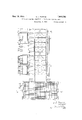
- Figure 1 is a more or less diagrammatic sectional elevation of a plant constructed and arranged in accordance with the invention, but with the left hand portion comprising the uptake shown turned at 90 to its proper position.
- F igure 2 is a section on theline 2-2 of Figure 3.
- Figure 3 is a section on the line 33 of Figure 4.
- Figure 4 is a sectional plan of a part of F1gure 1 on a somewhat larger scale but with the left hand portion shown in its proper position.
- Figure 5 is a section on the line 55 of Figure 4.
- Figure 6 is a diagrammatic sectional elevation showing the invention applied to an existing installation
- Figure 7 is a sectional plan of Figure 6.
- Any liquid deposit in such chamber or conduit may be received by a plurality of hopper-like or other collecting devices d or in a collecting channel or channels or in any other manner which will enable such deposit to be removed for treatment or disposal, and the primary chamber may be formed as or divided into a number of units separated from one another by scrubbers e of suitable form.
- the gas At the outlet end of the chamber or conduit I arrange for the gas to be submitted to a thorough douching by means of sprays f or curtains of fluid and at the same time the direction of fiow of the gas is altered and the gases passed through a series of scrubbers g of wood, fire-clay, metal tubes, earthenware, porcelain, or other suitable packings disposed or packed in absorption towers or chambers.
- the direction of fiow is preferably again changed (for example it may be reversed as at b) so as to facilitate the throwing-down or separation of a portion of the entrained liquid (which may be collected in the trough z') and the gases are then passed through an additional bank or banks of scrubbers 7c Z or the like wetted withan alkaline washwater or other fluid for final treatment, it being understood, however, that before such final treatment the gases may be passed through any number of series of scrubbers and may have their direction of flow changed any desired'number of times.
- moisture eliminators m which maybe constructed of Wood, earthenware, metal, or other suitable material and may be perforated or arranged in baflle form or may otherwise be constructed or disposed so as to prevent the emission of free moisture to the atmosphere, the gases finally passing from such eliminator plates to the chimney proper n where provision is made for the admixture of hot air with the gases so as to reduce the saturated condition of the s es a and to dilute the gases as finally discharged to atmosphere. For example, such air may be admitted to the gas stream from the chamber 0.
- I may ozonize part of the gases or I may introduce into the gases ozouized air either in addition to or in substitution for the introduction of ordinary air as above referred to, and while I prefer that the atomizing liquid in the initial stage should be at a temperature of about 175 to 180 F. while the liquid employed for I douching the gases is at atmospheric temperature yet it will be understood that arrangements are preferably made in' every stage of the process to vary the temperature of wash-water or otier alkaline water used tively.
- the liquid employed in the various stages of treatment may be re-circulated either wholly or in partwith or without suitable filtering or other treatment (such as passing through tanks containing iron or other catalyst).
- suitable filtering or other treatment such as passing through tanks containing iron or other catalyst.
- the velocity of flow of the gases may be varied as may be desired, and the time of Contact between the liquid and the gases adjusted to suit the particular application of the invention.
- flue gases or the like may be treated for the removal and elimination of grits, smoke, compounds of sulphur and other objectionable constituents therein, the nature of any reagents employed in the different stagesof the treatment being in general determined by the characterof the gases or the like to be treated.
- FIGS. 6 and 7 show the application of the invention to an existing installation in which space is more restricted, and as similar parts in these figures to those in the foregoing have been indicated by similar i reference letters, it is thought that no further description willbe needed to make this modification clear.
- the invention is not to be limited tothe foregoing details which are given purely byway of illustration to indicate the nature of the invention as I may arrange for horizontal, vertical and/or other suitable direction of How of the gases, and at such of the parts of the apparatus as involve a change in the direction of flow I may, if necessary or desirable, provide suitable collecting troughs or other devices with means for facilitating the removal therefrom of any substances, impurities, or materials deposited therein.
- Apparatus for removing obnoxious products from flue gases comprising, a series of primary chambers into which the line gases are admitted, scrubbers'between the chambers and forming the walls separating the chambers, said scrubbers being permeable to the gases passing from one chamber to another, spray nozzles in said chambers for washing the gases, means at the bottom of each chamber for collecting the water from the nozzles carrying the washed out gas products, a second chamber adapted to receive in its upper portion the sprayed gases from the primary chambers, means for douching the gases located in the upper portion of the second chamber, a scrubber in the second chamber beneath the douching means, the sides of the second chamber extending downwardly beyond the scrubber, means at the bottom of the second chamber for collecting the water and foreign matter washed from the gases in said second chamher, the sides of said second chamber having openings near their bottom for changing the direction of motion of the gases, 2.
- third chamber for the reception of the gases at its lower end also having a scrubber therein through
- Apparatus according to claim 1 and a moisture eliminator at said flue and through which the purified gases are passed after the final Washing operation.
- Apparatus according to claim 1 and including means in association with the primary chamber for separating the grit.
Description
May 16, 1933. s. L. PEARCE 1,908,782
APPARATUS FOR THE TREATMENT OF FLUE GASES AND THE LIKE Filed Feb. 6. 1930 6 Sheets-Sheet 1 IN \rewn IL 5. Pia rag May 16, 1933. s. L. PEARCE 1,908,782
APPARATUS FOR THE TREATMENT OF FLUE GASES AND THE LIKE Filed Feb. 6, 1930 6 Sheets- Sheet 2 ,5 Vlar May 16, 1933. S L, L98J82 APPARATUS FOR THE TREATMENT OF FLUE GASES AND THE LIKE Filed Feb. 6, 1930 6 Sheets-Sheet 3 g j, Fence,
May 15, 1933. v 5 L. PEARCE 1,9@8,782
APPARATUS FOR THE-TREATMENT OF FLUE GASES AND THE LIKE Filed Feb. 6, 1930 6 Sheets-Sheet 4 y 16, 933- s. L. PEARCE 1,908,782
APPARATUS FOR THE TREATMENT OF FLUE GASES AND THE LIKE Filed Feb. 6, 1930 6 Sheets-Sheet 5 S. L. PEARCE May 16, 1933.
APPARATUS FOR THE TREATMENT OF FLUE GASES AND THE LIKE 6 SheetS- -Sheet 6 Filed Feb. 6. 1930 Patented lt'lay 16, 1933 LQMSJSZ STANDEN LEONARD PEARCE, LONDON, ENG-LAND, ASSIGNOR OF ONE-HALF T0 LONDON POWER COMPANY LIMITED, 0F LONDON, ENGLAND APPARATUS FOR THE TREATMENT OF FLUE GASES AND-THE LIKE Application filed February 6, 1930, Serial No. 426,405, and in Great Britain July 16, 1929.
This invention has for its object to devise simple and efiective means for the treat ment of flue gases, residual trade gases and other gases, fumes or vapours ordinarily discharged into the atmosphere, whereby any obnoxious or disagreeable products or substances contained therein may be abstracted from such gases before final discharge so as to render the same entirely or substantially innocuous or such as not to constitute a source of annoyance to residents and others or damage to buildings and vegetation in the vicinity. r
The invention hasthe further advantage that any marketable or useful constituents or by-products that would otherwise be carried away with the gases or the like may be readily recovered. r l
According to my invention the gases or the like" before discharge are first led through a chamber or conduit, preferably containing free iron or other catalytic agent or agents, and provided with atomizing devices or other means for thoroughly saturating the gases (which may also be scrubbed insaid primary chamber) after which they are washed and scrubbed in other chambers or towers (or in another zone or zones of the same chamber), the direction of flowbeing preferably changed be tween successive operations so as to facilitate the separation from the gases 'of any impurities or substances abstracted by such operations. g
The invention also consists in a treatment according to the preceding paragraph according to which the gases before discharge and after preliminary treatment are ozonized or mixed with ozonized air.
The invention further comprises the appa-ratus for carrying out the herein described methods and other details and arrangements hereinafter described or indicated.
The accompanying drawings illustrate two modes of carrying out the invention.
Figure 1 is a more or less diagrammatic sectional elevation of a plant constructed and arranged in accordance with the invention, but with the left hand portion comprising the uptake shown turned at 90 to its proper position. i
Figure 3 is a section on the line 33 of Figure 4.
Figure 4 is a sectional plan of a part of F1gure 1 on a somewhat larger scale but with the left hand portion shown in its proper position. c
Figure 5 is a section on the line 55 of Figure 4.
Figure 6 is a diagrammatic sectional elevation showing the invention applied to an existing installation, and
Figure 7 is a sectional plan of Figure 6.
In carrying my invention into effect in one convenient manner as, for example, in its application to the treatment of flue gases from a boiler installation which would ordinarily be discharged through the chimney or uptake into the atmosphere in-the condition in which they leave thefurnaces, and as illustratedin Figures 1 to 5 when applying the invention to a new installation, I arrange for the flue gases issuing from the main flue to pass through a primary chamher a or conduit in which are located a num ber of fluid-atomizing units or sprays 7) disposed at the top and/or sides of the chamber or otherwiseconveniently located therein, the function of which is thoroughly t-o saturate the gases as they pass through such chamber or conduit, The sprays or the like may be associated with grit extractors 0 of standard cyclone type and which may,vfor example, comprise fans or blowers by which the gases are introduced into the primary chamber and in which the grits or other 'foreign matter is extracted from the gases by centrifugal action.
Any liquid deposit in such chamber or conduit may be received by a plurality of hopper-like or other collecting devices d or in a collecting channel or channels or in any other manner which will enable such deposit to be removed for treatment or disposal, and the primary chamber may be formed as or divided into a number of units separated from one another by scrubbers e of suitable form.
At the outlet end of the chamber or conduit I arrange for the gas to be submitted to a thorough douching by means of sprays f or curtains of fluid and at the same time the direction of fiow of the gas is altered and the gases passed through a series of scrubbers g of wood, fire-clay, metal tubes, earthenware, porcelain, or other suitable packings disposed or packed in absorption towers or chambers.
The direction of fiow is preferably again changed (for example it may be reversed as at b) so as to facilitate the throwing-down or separation of a portion of the entrained liquid (which may be collected in the trough z') and the gases are then passed through an additional bank or banks of scrubbers 7c Z or the like wetted withan alkaline washwater or other fluid for final treatment, it being understood, however, that before such final treatment the gases may be passed through any number of series of scrubbers and may have their direction of flow changed any desired'number of times.
After treatment with alkaline wash-water or the like the gases are conducted through moisture eliminators m which maybe constructed of Wood, earthenware, metal, or other suitable material and may be perforated or arranged in baflle form or may otherwise be constructed or disposed so as to prevent the emission of free moisture to the atmosphere, the gases finally passing from such eliminator plates to the chimney proper n where provision is made for the admixture of hot air with the gases so as to reduce the saturated condition of the s es a and to dilute the gases as finally discharged to atmosphere. For example, such air may be admitted to the gas stream from the chamber 0.
In some. cases I may ozonize part of the gases or I may introduce into the gases ozouized air either in addition to or in substitution for the introduction of ordinary air as above referred to, and while I prefer that the atomizing liquid in the initial stage should be at a temperature of about 175 to 180 F. while the liquid employed for I douching the gases is at atmospheric temperature yet it will be understood that arrangements are preferably made in' every stage of the process to vary the temperature of wash-water or otier alkaline water used tively.
The liquid employed in the various stages of treatment may be re-circulated either wholly or in partwith or without suitable filtering or other treatment (such as passing through tanks containing iron or other catalyst). The velocity of flow of the gases (whether caused by induced or forced draught) may be varied as may be desired, and the time of Contact between the liquid and the gases adjusted to suit the particular application of the invention.
Any desired arrangement of pumps, pipe lines, tanks and other appurtenances may be used to facilitate the circulation and/or recirculation of the liquid, air or other media employed. I
By means of this invention flue gases or the like may be treated for the removal and elimination of grits, smoke, compounds of sulphur and other objectionable constituents therein, the nature of any reagents employed in the different stagesof the treatment being in general determined by the characterof the gases or the like to be treated.
Figures 6 and 7 show the application of the invention to an existing installation in which space is more restricted, and as similar parts in these figures to those in the foregoing have been indicated by similar i reference letters, it is thought that no further description willbe needed to make this modification clear.
The invention is not to be limited tothe foregoing details which are given purely byway of illustration to indicate the nature of the invention as I may arrange for horizontal, vertical and/or other suitable direction of How of the gases, and at such of the parts of the apparatus as involve a change in the direction of flow I may, if necessary or desirable, provide suitable collecting troughs or other devices with means for facilitating the removal therefrom of any substances, impurities, or materials deposited therein.
I claim: I I
1. Apparatus for removing obnoxious products from flue gases, comprising, a series of primary chambers into which the line gases are admitted, scrubbers'between the chambers and forming the walls separating the chambers, said scrubbers being permeable to the gases passing from one chamber to another, spray nozzles in said chambers for washing the gases, means at the bottom of each chamber for collecting the water from the nozzles carrying the washed out gas products, a second chamber adapted to receive in its upper portion the sprayed gases from the primary chambers, means for douching the gases located in the upper portion of the second chamber, a scrubber in the second chamber beneath the douching means, the sides of the second chamber extending downwardly beyond the scrubber, means at the bottom of the second chamber for collecting the water and foreign matter washed from the gases in said second chamher, the sides of said second chamber having openings near their bottom for changing the direction of motion of the gases, 2. third chamber for the reception of the gases at its lower end also having a scrubber therein through which the gases pass upwardly, and a fiue above the third chamber to receive and emit the purified gases.
2. Apparatus according to claim 1, and means for admitting air to the gases asthey enter the flue above the third chamber.
3. Apparatus according to claim 1, and a moisture eliminator at said flue and through which the purified gases are passed after the final Washing operation.
4. Apparatus according to claim 1, and including means in association with the primary chamber for separating the grit.
In testimony whereof I have signed my name to this specification.
STANDEN LEONARD PEARCE.
Applications Claiming Priority (1)
| Application Number | Priority Date | Filing Date | Title |
|---|---|---|---|
| GB1908782X | 1929-07-16 |
Publications (1)
| Publication Number | Publication Date |
|---|---|
| US1908782A true US1908782A (en) | 1933-05-16 |
Family
ID=10893375
Family Applications (1)
| Application Number | Title | Priority Date | Filing Date |
|---|---|---|---|
| US426405A Expired - Lifetime US1908782A (en) | 1929-07-16 | 1930-02-06 | Apparatus for the treatment of flue gases and the like |
Country Status (1)
| Country | Link |
|---|---|
| US (1) | US1908782A (en) |
Cited By (11)
| Publication number | Priority date | Publication date | Assignee | Title |
|---|---|---|---|---|
| US3237381A (en) * | 1961-07-05 | 1966-03-01 | Aquitaine Petrole | Method and means for treating moving gases by liquids |
| US3920794A (en) * | 1972-09-28 | 1975-11-18 | Little Inc A | Method for removal of sulfur dioxide from gases |
| US3948608A (en) * | 1972-03-24 | 1976-04-06 | Weir Jr Alexander | Apparatus for treating stack gases |
| US4369167A (en) * | 1972-03-24 | 1983-01-18 | Weir Jr Alexander | Process for treating stack gases |
| US4481170A (en) * | 1972-03-24 | 1984-11-06 | Weir Jr Alexander | Apparatus for treating stack gases |
| US5403568A (en) * | 1993-03-05 | 1995-04-04 | Dravo Lime Company | Horizontal wet scrubbing apparatus and method for removing sulfur dioxide from a gaseous stream |
| EP1062018A1 (en) * | 1997-10-22 | 2000-12-27 | Clue AS. | A scrubber for the treatment of flue gases |
| US6235256B1 (en) * | 1995-09-07 | 2001-05-22 | Austrian Energy & Environment Scp/Waagner-Biro Gmbh | Process and device for the scrubbing acidic gases |
| US6267804B1 (en) * | 1996-05-08 | 2001-07-31 | Tas Enterprise, Llc. | Wet gas stripper |
| US20040079235A1 (en) * | 2002-10-24 | 2004-04-29 | Vrotsos Jeffery J. | Flue gas desulfurization system with a stepped tray |
| US10245546B1 (en) | 2018-08-22 | 2019-04-02 | H & H Inventions & Enterprises, Inc. | Exhaust gas purification method and system |
-
1930
- 1930-02-06 US US426405A patent/US1908782A/en not_active Expired - Lifetime
Cited By (15)
| Publication number | Priority date | Publication date | Assignee | Title |
|---|---|---|---|---|
| US3237381A (en) * | 1961-07-05 | 1966-03-01 | Aquitaine Petrole | Method and means for treating moving gases by liquids |
| US3948608A (en) * | 1972-03-24 | 1976-04-06 | Weir Jr Alexander | Apparatus for treating stack gases |
| US4102982A (en) * | 1972-03-24 | 1978-07-25 | Weir Jr Alexander | Process for treating stack gases |
| US4369167A (en) * | 1972-03-24 | 1983-01-18 | Weir Jr Alexander | Process for treating stack gases |
| US4481170A (en) * | 1972-03-24 | 1984-11-06 | Weir Jr Alexander | Apparatus for treating stack gases |
| US3920794A (en) * | 1972-09-28 | 1975-11-18 | Little Inc A | Method for removal of sulfur dioxide from gases |
| US5403568A (en) * | 1993-03-05 | 1995-04-04 | Dravo Lime Company | Horizontal wet scrubbing apparatus and method for removing sulfur dioxide from a gaseous stream |
| US6235256B1 (en) * | 1995-09-07 | 2001-05-22 | Austrian Energy & Environment Scp/Waagner-Biro Gmbh | Process and device for the scrubbing acidic gases |
| US6267804B1 (en) * | 1996-05-08 | 2001-07-31 | Tas Enterprise, Llc. | Wet gas stripper |
| EP1062018A1 (en) * | 1997-10-22 | 2000-12-27 | Clue AS. | A scrubber for the treatment of flue gases |
| EP1062018A4 (en) * | 1997-10-22 | 2001-10-17 | Clue As | A scrubber for the treatment of flue gases |
| US20040079235A1 (en) * | 2002-10-24 | 2004-04-29 | Vrotsos Jeffery J. | Flue gas desulfurization system with a stepped tray |
| US6923852B2 (en) | 2002-10-24 | 2005-08-02 | The Babcock & Wilcox Company | Flue gas desulfurization system with a stepped tray |
| US10245546B1 (en) | 2018-08-22 | 2019-04-02 | H & H Inventions & Enterprises, Inc. | Exhaust gas purification method and system |
| US10905993B2 (en) | 2018-08-22 | 2021-02-02 | H & H Inventions & Enterprises, Inc. | Exhaust gas purification method and system |
Similar Documents
| Publication | Publication Date | Title |
|---|---|---|
| US3957464A (en) | Process for removing particulates from a gas | |
| US1908782A (en) | Apparatus for the treatment of flue gases and the like | |
| US3856487A (en) | Gas scrubber | |
| US4110088A (en) | Apparatus and method for removal of pollutants from flue gas | |
| JPS62110732A (en) | Method for purifying gas | |
| US3336733A (en) | Gas scrubber | |
| US3993448A (en) | Scrubber and combustion apparatus | |
| CN109647114B (en) | Flue gas treatment system and process for high-polymer waterproof coiled material production line | |
| US3183645A (en) | Process for deodorization of an odiferous atmosphere | |
| AU652617B2 (en) | Multigas scrubber | |
| US3210914A (en) | Fume scrubber | |
| US3616597A (en) | Method for treating and purifying air | |
| US2997132A (en) | Method for the ventilating of plants for the manufacture of aluminium or similar products | |
| US4784835A (en) | Unit for filtration and neutralization of sulfurous anhydride contained in smoke from a boiler | |
| US3817713A (en) | Apparatus for the purification of air with a mercury vapor content | |
| US3745745A (en) | Scrubbing apparatus and method | |
| US1952308A (en) | Fluid treating device | |
| US3760567A (en) | Smoke and air cleaner assembly | |
| US1866443A (en) | Scrubbing and absorbing apparatus | |
| US3221475A (en) | Wet electrostatic precipitator | |
| DE3321961C2 (en) | ||
| US1779282A (en) | Boiler-house smoke-disposal process | |
| US3492789A (en) | Method and apparatus for exhausting gases from industrial buildings | |
| JPS6247569B2 (en) | ||
| US3105103A (en) | Apparatus for treating a gaseous mixture |