US1982957A - Outlet box and hanger bar - Google Patents
Outlet box and hanger bar Download PDFInfo
- Publication number
- US1982957A US1982957A US492675A US49267530A US1982957A US 1982957 A US1982957 A US 1982957A US 492675 A US492675 A US 492675A US 49267530 A US49267530 A US 49267530A US 1982957 A US1982957 A US 1982957A
- Authority
- US
- United States
- Prior art keywords
- hanger bar
- outlet box
- members
- plates
- box
- Prior art date
- Legal status (The legal status is an assumption and is not a legal conclusion. Google has not performed a legal analysis and makes no representation as to the accuracy of the status listed.)
- Expired - Lifetime
Links
Images

Classifications
-
- H—ELECTRICITY
- H02—GENERATION; CONVERSION OR DISTRIBUTION OF ELECTRIC POWER
- H02G—INSTALLATION OF ELECTRIC CABLES OR LINES, OR OF COMBINED OPTICAL AND ELECTRIC CABLES OR LINES
- H02G3/00—Installations of electric cables or lines or protective tubing therefor in or on buildings, equivalent structures or vehicles
- H02G3/02—Details
- H02G3/08—Distribution boxes; Connection or junction boxes
- H02G3/12—Distribution boxes; Connection or junction boxes for flush mounting
- H02G3/123—Distribution boxes; Connection or junction boxes for flush mounting in thin walls
- H02G3/126—Distribution boxes; Connection or junction boxes for flush mounting in thin walls with supporting means for mounting on a single wall stud
-
- Y—GENERAL TAGGING OF NEW TECHNOLOGICAL DEVELOPMENTS; GENERAL TAGGING OF CROSS-SECTIONAL TECHNOLOGIES SPANNING OVER SEVERAL SECTIONS OF THE IPC; TECHNICAL SUBJECTS COVERED BY FORMER USPC CROSS-REFERENCE ART COLLECTIONS [XRACs] AND DIGESTS
- Y10—TECHNICAL SUBJECTS COVERED BY FORMER USPC
- Y10S—TECHNICAL SUBJECTS COVERED BY FORMER USPC CROSS-REFERENCE ART COLLECTIONS [XRACs] AND DIGESTS
- Y10S248/00—Supports
- Y10S248/906—Electrical outlet box support
Definitions
- This invention relates to outlet boxes and hanger bars and particularly to hanger bars having means for receiving or holding an outlet box.
- the primary object of the invention is to provide a new and improved telescoping hanger bar which is provided with novel means whereby an outlet box may be connected to the hanger bar.
- Another object of the invention is to provide a telescoping hanger bar for outlet boxes whereby the outlet box may be adjusted horizontally, laterally, and vertically.
- the invention comprises in general a twopiece hanger bar, one of which slidingly engages the other whereby lateral adjustment of one part is maintained relative to the other part.
- An outlet box slidingly engages the hanger bar to permit lateral adjustment of the outlet box relative to the hanger bar.
- An end support is provided for temporarily holding the hanger bar and its attachedl outlet box in position between joists.
- the ends of the hanger bar are interlockingly or interttingly engaged with the end plate and the hanger bar may be adjusted vertically relative to the end plate.
- the hanger bar and its cooperating outlet b x is adapted tovbe temporarily supported in p ace, then finally adjusted to position, and then permanently fastened in adjusted position.
- the hanger bar permits horizontal, vertical, and lateral adjustment.
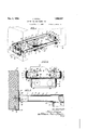
- Fig. 1 is a detail perspectiveview of an improved hanger bar showing the manner in which it may be applied between joists, rafters or studs.
- Fig. 2 is a detail sectional view on the line 2--2 of Fig. 1.
- Fig. 3 is a detail longitudinal sectional view.
- Fig. 4 is a detail perspective view of a modi- 60 ed form of hanger bar and outlet box.
- Fig. 5 is a detail sectional view on the line 5-5 of Fig. 4, and showing a plaster ring arranged on the outlet box.
- Fig. 6 is a detail perspective of the plate or 65 carrier shown in section in Fig. 5.
- the particular hanger bar and outlet box as shown in Figs. 1 to 3, comprises a pair of U-shaped members 1 and 2 which when arranged together, form a supporting frame.
- the member 2 is provided with an end attaching portion 3 and inwardly extending legs 4 and 5.
- the member 1 has an end attaching portion 6 and inwardly extending legs 'I and 8 for telescopically receiving the legs 4 and 5 respectively of 75 the member 2.
- the member 1 has rolled-over upper and lower edges 9 for telescopically holding the legs 4 and 5 of the member 2.
- the member 2 has its upper and lower edges rounded as indicated at 10, Fig. 2, for permitting free sliding movement of the member 2 relative to the member 1.
- An outlet box l1 is provided with a plate or carrier 12 which has rolled-over edges 13 which engage the legs 7 and 8 of the member 1 and 65 is freely slidable thereon.
- the box 11 -and its cooperating carrier or plate 12 may be made as a single unit, or the box may be made separately and fastened to the plate 12 in any desirable manner.
- the box and its cooperating carrier is provided with knock-outs 14 through which the electric conduit or cable extends in the usual manner. If the carrier is made as a separable unit, knockouts are arranged in both the carrier and box. and these knock-outs are adapted to be brought into alinement for the reception of the conduit or cable.
- End plates 15 are provided for attaching the hanger bar and its cooperating outlet box to joists or studs 16.
- the plates 15 each com- 100 prise a body portion 16 which is bent at 17 to provide the inturned flange 18.
- Integral upstanding prongs 19 are formed on the ange 18 and are adapted to be driven into the joist 15' for temporarily supporting the hanger bar' and 105 its cooperating outlet box.
- Upper and lower lugs 20 are struck out from the body 15 of the end plates 15 and are adapted to receive the ends 6 and 3 of the members 1 and 2 respectively.
- the ends 3 and. 6, Fig. 2 may be provided with V110 ⁇ tion relative to Figs. 1' to 3.
- the plates 15 are also provided with spaced elongated slots 23 to receive nails or other fastening means 24 for permitting fastening of the plate to the joists.
- Ears 25 may be struck up from the body of the outlet box plate 12 for fastening the outlet box permanently to the hanger bar when the outlet box is arranged in adjusted position.
- the plates 15 are first driven in position due to the engagement of the prongs 18 with the joists 16.
- the outlet box 11 is then shifted along the hanger bar until it attains the proper horizontal position desired.
- the hanger bar may then be shifted laterally in the end plates until the proper position of the outlet box laterally is obtained.
- the hanger bar and its cooperating outlet box can then be moved vertically due to the free movement provided between the lugs 20 and the ends of the hanger bar.
- the nails 24 may be then driven in position, thereby rigidly holding the hanger bar in proper position relative to the joists 16.l
- the ears 25 are then crimped, such as by pinching with pliers, to maintain the outlet box rigid with the hanger bar and to prevent slidable movement thereon.
- the hanger bar and outlet box shown in Figs. 4 to 6 includes the U-shaped members 1 and 2 which telescope with each 'other to provide a supporting frame as set forth in the specifica-
- the legs 4 and 5 of the member 2 are crimped or' bent as clearly shown in Fig. 2 to reinforce the member and to permit it to slide freely in the member 1.
- the carrier or plate 12 which may be a separate member or an integral part of the box 11, slides Within the frame as shown in Figs. 4 and 5, instead of engaging the outside of the framel as shown in Figs. 1 to 3.
- the carrier and box are also provided with knock-outs as previously described relativeA to the carrier and plate shown in Figs. 1 to 3.
- lugs or ears form means which are received in the frame and permit slidable movement. of the box and its integral or cooperating carrier relative to the frame.
- the box 11, Fig. 5 may be provided with an inwardly extending peripheral flange 34 to which a cooperating plaster ring 35 is attached in any convenient manner such as-by the screws 36.
- the plaster ring is for the purpose of reducing the outlet box opening and is required by ordinanceV in some localities. 'I'he plaster 37 comes flush with the lower end of the ring as clearly shown in Fig. 5.
- the box may be shifted vertically as well as horizontally, by moving the frame upwardly or downwardly or by using the end attaching plates or members 15.
- 'I'he frame is preferably made of heavy sheet.
- iron or stamped steel 'and is designed to carry a suspended load of two hundred pounds or more as requiredby ordinance in many jurisdictions.
- the hanger bar may be fastened directly to the supporting membersby ydirectly fastening l the end members 3 and 6 directly to the supporting members or the hanger bar may be mounted in the end plates 15, if desired,
- outlet box has been used to explain the invention, this term is to be given its broadest interpretation and includes any kind of an electrical receptacle, such as a switch box.
- the invention provides a rigid and durable hanger bar capable 'of carrying a relatively heavy load and permits the outlet box to be moved vertically, horizontally, and laterally for adjustment.
- the telescoping of one member of the hanger bar relative to its cooperating member permits end adjustment between joists, and the end plate construction permits the hanger bar to be temporarily supported in place, allowing for vertical adjustment of the hanger bar.
- nails hold the hanger bar securely in adjusted position and the bending of the lugs on the outlet box maintains the-outlet box'in proper adjusted position.
- 'Ihe entire structure is strong and durable inl construction, mayv be quickly and readily applied, and may be readily and economically manufactured.
- a hanger bar adapted to be mounted between joists, end plates for supporting the bar, turned up prongs on said plates for temporarily supporting said plates to said joists, said hanger bar being adjustably supported by said plates between said joists, and 120 means passing through the hanger bar and the plates for rigidly supporting said plates and hanger in position to the joists.
- a hanger bar plates for ⁇ supporting the bar, each plate comprising a body portion, a flange on said body portion, prongs formed on said plate andf adapted to be driven into supports for temporarily supporting said plate, oppositely disposed ears struck from the body of said plate and adapted to support ,130 the hanger bar therebetween and permitting adjustment of said hanger bar, said plate having elongated slots therein, said hanger bar having ⁇ holes therein in alinement with said slots, and fastening means passing through said holes and slots for flxedly mounting said hanger bar in position.
- a hanger bar plates for supporting the bar, each plate comprising a body portion, a flange on said body portion and 4.
- a hanger bar comprising a pair of end members, legs on said end members and having telescopic relationship, a supporting plate having spaced ears struck therefrom, the ears having their free ends facing each other, said end members having notches cut therefrom and mounted between said ears, the distance between the notches being greater than the distance between the free ends of said ears.
- plates having integral spaced ears struck therefrom, said ears each having an attached end and a free end
- a hanger bar having end members arranged between the spaced ears, said end members having oppositely disposed notched-out portions, the distance between said notched-out portions being greater than the distance between the free ends of said ears but less than the distance between the attached ends of the ears, whereby the end members may be moved a predetermined distance between the ears and still be guided thereby.
- a hanger bar comprising end members, end plates for supporting said members, said end plates having spaced apart struck out lugs between which the end members are arranged, the end members having vertical adjustment between said lugs, said end plates having vertical slots therein, said end members having openings therethrough adapted for alinement with the slots in the plate, and fastening means passing through said holes and slots.
- a telescoping hanger bar having an outlet box slidingly supported by the hanger bar
- the combination with an end bracket adjustably receiving the hanger bar, and means passing through the hanger bar and end plate for fastening the plate to a supporting member and the hanger bar to the plate in adjusted position.
- a hanger bar comprising a pair of U-shaped members each including a pair of legs and end connecting parts, the legs of one member telescoping with the legs of the other member, an outlet box slidingly engaging the telescoping legs of the said member, and fastening end plates adapted to be fastened to a support and adjustably receiving the end connecting parts of said members.
- a hanger bar having a pair of telescoping members and an outlet box slidingly supported by said members, the combination of end plates adapted to be fastened to a support, and means on the end plates and engaging the members and adjustably receiving the said members.
- a hanger bar having a pair of telescoping members and an outlet box slidingly supported by said members, the combination of end plates adapted to be fastened to a support, oppositely disposed lugs struck up from the end plates and adjustably receiving the members therebetween, means on the plates temporarily supporting the plates and the members, and fastening means passing through the plates and members for xing the plates and members in position on said support.
- a telescoping hanger bar having an outlet box slidably mounted thereon, the combination of an end bracket adjustably receiving the hanger bar, said hanger bar having lateral and vertical adjustment in respect to said end bracket, and means for fixing the end bracket and hanger bar in adjusted position.
- a telescoping hanger bar having an outlet box slidably mounted thereon, the com bination of an end bracket adjustably receii. the hanger bar, said hanger bar having lateia' andv vertical adjustment in respect to said end bracket, and means for fastening the end bracket and hanger bar in adjusted position to a supporting member.
- a telescoping hanger bar having an outlet box slidably mounted thereon, the combination of an end bracket adjustably receiving the hanger bar, said hanger bar having lateral and vertical adjustment in respect to said end bracket, and means passing through the hanger bar and bracket for fastening the bracket to a supporting member and the hanger bar to the bracket in adjusted position.
Description
. 4, 1934. J. KNELL OUTLET BOX AND HANGER BAR Filed NOV. l, 1930 2 Sheets-Sheet l Illlll -IIIIIII I l 1111. vrllll' ,a llllllll Dec. 4, 1934. L KNELL 1,982,957
OUTLET Box AND HANGER BAR Filed Nov. 1, 195o 2 sheets-sheet 2 [NVE/V T0R:- Jof//v HNELL de/@Aman @Mx/72H14.
Patented Dec. 4, 1934 UNITED STATESl OUTLET BOX AND HANGER John Knell, Aurora, Ill., assigner to All-Steel- IEquip Company, Aurora, Ill., a. corporation of Illinois Application November 1, 1930, Serial No. 492,675
13 Claims.
This invention relates to outlet boxes and hanger bars and particularly to hanger bars having means for receiving or holding an outlet box.
The primary object of the invention is to provide a new and improved telescoping hanger bar which is provided with novel means whereby an outlet box may be connected to the hanger bar.
Another object of the invention is to provide a telescoping hanger bar for outlet boxes whereby the outlet box may be adjusted horizontally, laterally, and vertically.
Other important objects of the invention are to provide a two-piece hanger bar, one of which telescopes with the other, and which is provided with novel means whereby the hanger bar may engage a rafter, stud, or joist for temporarily holding it in place; the provision of means for adjustably supporting an outlet box and permitting lateral and vertical adjustment thereof; and the provision of means for temporarily supporting the hanger bar for permitting lateral adjustment of the hanger bar, for permitting lateral adjustment of an outlet box on the hanger bar, and for permitting vertical adjustment of the hanger bar and outlet box relative to the supporting means.
Numerous other objects and advantages will be apparent throughout the progress of the following specication.
The invention comprises in general a twopiece hanger bar, one of which slidingly engages the other whereby lateral adjustment of one part is maintained relative to the other part. An outlet box slidingly engages the hanger bar to permit lateral adjustment of the outlet box relative to the hanger bar.
An end support is provided for temporarily holding the hanger bar and its attachedl outlet box in position between joists. The ends of the hanger bar are interlockingly or interttingly engaged with the end plate and the hanger bar may be adjusted vertically relative to the end plate. The hanger bar and its cooperating outlet b x is adapted tovbe temporarily supported in p ace, then finally adjusted to position, and then permanently fastened in adjusted position. The hanger bar permits horizontal, vertical, and lateral adjustment. l
The accompanying drawings illustrate a selected embodiment of the invention and the -views therein are as follows:
Fig. 1 is a detail perspectiveview of an improved hanger bar showing the manner in which it may be applied between joists, rafters or studs.
Fig. 2 is a detail sectional view on the line 2--2 of Fig. 1.
Fig. 3 is a detail longitudinal sectional view.
Fig. 4 is a detail perspective view of a modi- 60 ed form of hanger bar and outlet box.
Fig. 5 is a detail sectional view on the line 5-5 of Fig. 4, and showing a plaster ring arranged on the outlet box.
Fig. 6 is a detail perspective of the plate or 65 carrier shown in section in Fig. 5.
The particular hanger bar and outlet box as shown in Figs. 1 to 3, comprises a pair of U-shaped members 1 and 2 which when arranged together, form a supporting frame. The member 2 is provided with an end attaching portion 3 and inwardly extending legs 4 and 5. The member 1 has an end attaching portion 6 and inwardly extending legs 'I and 8 for telescopically receiving the legs 4 and 5 respectively of 75 the member 2. The member 1 has rolled-over upper and lower edges 9 for telescopically holding the legs 4 and 5 of the member 2. The member 2 has its upper and lower edges rounded as indicated at 10, Fig. 2, for permitting free sliding movement of the member 2 relative to the member 1.
An outlet box l1 is provided with a plate or carrier 12 which has rolled-over edges 13 which engage the legs 7 and 8 of the member 1 and 65 is freely slidable thereon. The box 11 -and its cooperating carrier or plate 12 may be made as a single unit, or the box may be made separately and fastened to the plate 12 in any desirable manner. The box and its cooperating carrier is provided with knock-outs 14 through which the electric conduit or cable extends in the usual manner. If the carrier is made as a separable unit, knockouts are arranged in both the carrier and box. and these knock-outs are adapted to be brought into alinement for the reception of the conduit or cable.
oppositely disposed notches 21 to permit vertical adjustment of the hanger bar relative to the plates 15 as the width of the ends 3 and 6 at the notches is less than the distance between the attached ends 22 of the lugs 20. The plates 15 are also provided with spaced elongated slots 23 to receive nails or other fastening means 24 for permitting fastening of the plate to the joists.
In arranging an outlet box in position, the plates 15 are first driven in position due to the engagement of the prongs 18 with the joists 16.
The outlet box 11 is then shifted along the hanger bar until it attains the proper horizontal position desired. The hanger bar may then be shifted laterally in the end plates until the proper position of the outlet box laterally is obtained. The hanger bar and its cooperating outlet box can then be moved vertically due to the free movement provided between the lugs 20 and the ends of the hanger bar. After the proper vertical position of the outlet box is at-v tained the nails 24 may be then driven in position, thereby rigidly holding the hanger bar in proper position relative to the joists 16.l The ears 25 are then crimped, such as by pinching with pliers, to maintain the outlet box rigid with the hanger bar and to prevent slidable movement thereon.
The hanger bar and outlet box shown in Figs. 4 to 6, includes the U-shaped members 1 and 2 which telescope with each 'other to provide a supporting frame as set forth in the specifica- The legs 4 and 5 of the member 2 are crimped or' bent as clearly shown in Fig. 2 to reinforce the member and to permit it to slide freely in the member 1. The carrier or plate 12, which may be a separate member or an integral part of the box 11, slides Within the frame as shown in Figs. 4 and 5, instead of engaging the outside of the framel as shown in Figs. 1 to 3. The carrier and box are also provided with knock-outs as previously described relativeA to the carrier and plate shown in Figs. 1 to 3. Thek inner sliding plate 12' shown in Fig. 6 is slit at 30 and then bent along the lines 31 to provide the upper and lower lugs or ears 32 and 33 respectively. These lugs or ears form means which are received in the frame and permit slidable movement. of the box and its integral or cooperating carrier relative to the frame.
The box 11, Fig. 5, may be provided with an inwardly extending peripheral flange 34 to which a cooperating plaster ring 35 is attached in any convenient manner such as-by the screws 36. The plaster ring is for the purpose of reducing the outlet box opening and is required by ordinanceV in some localities. 'I'he plaster 37 comes flush with the lower end of the ring as clearly shown in Fig. 5. Regardless of whether or not the plaster ring is employed, the box may be shifted vertically as well as horizontally, by moving the frame upwardly or downwardly or by using the end attaching plates or members 15.
'I'he frame is preferably made of heavy sheet.
iron or stamped steel 'and is designed to carry a suspended load of two hundred pounds or more as requiredby ordinance in many jurisdictions.
The hanger bar may be fastened directly to the supporting membersby ydirectly fastening l the end members 3 and 6 directly to the supporting members or the hanger bar may be mounted in the end plates 15, if desired,
'I'he particular outlet boxes herein shown are smaller than'the distance between the legs of the frame but it is to be understood that the box may be made considerably larger, if desired. The box shown in Fig. 1 could be made as wide as desired and could extend beyond the legs of the frame.` `While the term outlet box has been used to explain the invention, this term is to be given its broadest interpretation and includes any kind of an electrical receptacle, such as a switch box.
The invention provides a rigid and durable hanger bar capable 'of carrying a relatively heavy load and permits the outlet box to be moved vertically, horizontally, and laterally for adjustment. The telescoping of one member of the hanger bar relative to its cooperating member permits end adjustment between joists, and the end plate construction permits the hanger bar to be temporarily supported in place, allowing for vertical adjustment of the hanger bar. 'Ihe nails hold the hanger bar securely in adjusted position and the bending of the lugs on the outlet box maintains the-outlet box'in proper adjusted position. 'Ihe entire structure is strong and durable inl construction, mayv be quickly and readily applied, and may be readily and economically manufactured.
Changes may be made in the form, construction, and arrangement of the various parts without departing from the spirit of the invention or sacrificing any of its advantages, and the right is hereby reserved to makek all such changes as fairly fall within the scope of the following claims.
'I'he invention is hereby claimed as follows:
1. In combination, a hanger bar adapted to be mounted between joists, end plates for supporting the bar, turned up prongs on said plates for temporarily supporting said plates to said joists, said hanger bar being adjustably supported by said plates between said joists, and 120 means passing through the hanger bar and the plates for rigidly supporting said plates and hanger in position to the joists.
2. In combination, a hanger bar, plates for `supporting the bar, each plate comprising a body portion, a flange on said body portion, prongs formed on said plate andf adapted to be driven into supports for temporarily supporting said plate, oppositely disposed ears struck from the body of said plate and adapted to support ,130 the hanger bar therebetween and permitting adjustment of said hanger bar, said plate having elongated slots therein, said hanger bar having `holes therein in alinement with said slots, and fastening means passing through said holes and slots for flxedly mounting said hanger bar in position.
3. In combination, a hanger bar, plates for supporting the bar, each plate comprising a body portion, a flange on said body portion and 4. A hanger bar comprising a pair of end members, legs on said end members and having telescopic relationship, a supporting plate having spaced ears struck therefrom, the ears having their free ends facing each other, said end members having notches cut therefrom and mounted between said ears, the distance between the notches being greater than the distance between the free ends of said ears.
5. In combination, plates having integral spaced ears struck therefrom, said ears each having an attached end and a free end, a hanger bar having end members arranged between the spaced ears, said end members having oppositely disposed notched-out portions, the distance between said notched-out portions being greater than the distance between the free ends of said ears but less than the distance between the attached ends of the ears, whereby the end members may be moved a predetermined distance between the ears and still be guided thereby.
6. A hanger bar comprising end members, end plates for supporting said members, said end plates having spaced apart struck out lugs between which the end members are arranged, the end members having vertical adjustment between said lugs, said end plates having vertical slots therein, said end members having openings therethrough adapted for alinement with the slots in the plate, and fastening means passing through said holes and slots.
'7. In a telescoping hanger bar having an outlet box slidingly supported by the hanger bar, the combination with an end bracket adjustably receiving the hanger bar, and means passing through the hanger bar and end plate for fastening the plate to a supporting member and the hanger bar to the plate in adjusted position.
8. A hanger bar comprising a pair of U-shaped members each including a pair of legs and end connecting parts, the legs of one member telescoping with the legs of the other member, an outlet box slidingly engaging the telescoping legs of the said member, and fastening end plates adapted to be fastened to a support and adjustably receiving the end connecting parts of said members.
9. In a hanger bar having a pair of telescoping members and an outlet box slidingly supported by said members, the combination of end plates adapted to be fastened to a support, and means on the end plates and engaging the members and adjustably receiving the said members.
10. In a hanger bar having a pair of telescoping members and an outlet box slidingly supported by said members, the combination of end plates adapted to be fastened to a support, oppositely disposed lugs struck up from the end plates and adjustably receiving the members therebetween, means on the plates temporarily supporting the plates and the members, and fastening means passing through the plates and members for xing the plates and members in position on said support.
11. In a telescoping hanger bar having an outlet box slidably mounted thereon, the combination of an end bracket adjustably receiving the hanger bar, said hanger bar having lateral and vertical adjustment in respect to said end bracket, and means for fixing the end bracket and hanger bar in adjusted position.
12. In a telescoping hanger bar having an outlet box slidably mounted thereon, the com bination of an end bracket adjustably receii. the hanger bar, said hanger bar having lateia' andv vertical adjustment in respect to said end bracket, and means for fastening the end bracket and hanger bar in adjusted position to a supporting member.
13. In a telescoping hanger bar having an outlet box slidably mounted thereon, the combination of an end bracket adjustably receiving the hanger bar, said hanger bar having lateral and vertical adjustment in respect to said end bracket, and means passing through the hanger bar and bracket for fastening the bracket to a supporting member and the hanger bar to the bracket in adjusted position.
` JOHN KNEIL.
Priority Applications (1)
| Application Number | Priority Date | Filing Date | Title |
|---|---|---|---|
| US492675A US1982957A (en) | 1930-11-01 | 1930-11-01 | Outlet box and hanger bar |
Applications Claiming Priority (1)
| Application Number | Priority Date | Filing Date | Title |
|---|---|---|---|
| US492675A US1982957A (en) | 1930-11-01 | 1930-11-01 | Outlet box and hanger bar |
Publications (1)
| Publication Number | Publication Date |
|---|---|
| US1982957A true US1982957A (en) | 1934-12-04 |
Family
ID=23957183
Family Applications (1)
| Application Number | Title | Priority Date | Filing Date |
|---|---|---|---|
| US492675A Expired - Lifetime US1982957A (en) | 1930-11-01 | 1930-11-01 | Outlet box and hanger bar |
Country Status (1)
| Country | Link |
|---|---|
| US (1) | US1982957A (en) |
Cited By (58)
| Publication number | Priority date | Publication date | Assignee | Title |
|---|---|---|---|---|
| US2432555A (en) * | 1946-12-26 | 1947-12-16 | Kelton Mfg Co | Support for outlet boxes |
| US2639816A (en) * | 1950-03-03 | 1953-05-26 | Hazel D Fogg | Clothes drying rack |
| US2930564A (en) * | 1956-11-13 | 1960-03-29 | Robert W Maier | Fixture support for hung ceilings |
| US3039729A (en) * | 1959-07-24 | 1962-06-19 | Sr Francis E Nagle | Lighting fixture support |
| US3131901A (en) * | 1960-11-25 | 1964-05-05 | James E Coleman | Pen stud partition wall outlet box hanger |
| US3148698A (en) * | 1962-03-01 | 1964-09-15 | Raymond L Arnold | Prefabricated water supply and drain unit for washing machines |
| US3162413A (en) * | 1962-04-26 | 1964-12-22 | Andrew M Hexdall | Bar hanger |
| US3312770A (en) * | 1964-04-16 | 1967-04-04 | Benner Nawman Inc | Service box assembly |
| US3425655A (en) * | 1967-04-14 | 1969-02-04 | Cletus V Cogdill | Universal bar hanger |
| US3834658A (en) * | 1972-02-22 | 1974-09-10 | P Theodorides | Outlet box with adjustable mounting |
| US4165851A (en) * | 1977-09-28 | 1979-08-28 | Slater Electric Inc. | Adjustably lockable bar hanger for ceiling boxes and the like |
| US4717101A (en) * | 1986-02-10 | 1988-01-05 | Harrod Andrew S | Adjustable backing board bracket |
| US5114105A (en) * | 1990-11-08 | 1992-05-19 | Young John A | Electrical box support bracket |
| US5209444A (en) * | 1989-01-26 | 1993-05-11 | B-Line Systems, Inc. | Support for an electrical box |
| US5330137A (en) * | 1993-01-04 | 1994-07-19 | Oliva John H | Apparatus and method for mounting an electrical box between studs in a wall |
| US5623789A (en) * | 1994-09-12 | 1997-04-29 | Kidwell; Steven A. | Pitch stabilizing, positionable eaves-overhang light support assembly |
| US5722557A (en) * | 1996-11-05 | 1998-03-03 | Smith; Richard D. | Fire extinguisher enclosure |
| US5927667A (en) * | 1996-09-27 | 1999-07-27 | Hubbell Incorporated | Electrical box mounting bracket |
| US5938157A (en) * | 1995-01-12 | 1999-08-17 | Reiker; Kenneth H. | Fan brace slide support |
| US6098945A (en) * | 1998-03-19 | 2000-08-08 | Hubbell Incorporated | Mounting bracket and supporting brace |
| US6461016B1 (en) | 2000-10-25 | 2002-10-08 | Hubbell Incorporated | Adjustable recessed downlight |
| US6519791B2 (en) | 2001-07-03 | 2003-02-18 | Securus, Inc. | Stub-out bar |
| US6595476B1 (en) | 2001-07-20 | 2003-07-22 | Donald B. Edwards | Acoustic ceiling box support |
| US6803521B2 (en) * | 2001-04-25 | 2004-10-12 | Illini Electrical Sales, Inc. | Floor stand having parallel uprights of adjustable lengths, for electrical box having plaster ring |
| US20050067180A1 (en) * | 2003-09-29 | 2005-03-31 | Cong Dinh | Combination mounting bracket and adapter plate for mounting electrical boxes |
| US20060071133A1 (en) * | 2004-10-04 | 2006-04-06 | Target Brands, Inc. | Bracket for retail store display systems |
| US20060243874A1 (en) * | 2005-04-29 | 2006-11-02 | Stacy Fifer | Device for holding changeable element |
| US7154040B1 (en) * | 2006-01-09 | 2006-12-26 | Tompkins Philip M | Support bracket for electrical junction box |
| US20070084617A1 (en) * | 2003-09-29 | 2007-04-19 | Thomas & Betts International, Inc. | Adjustable mounting bracket assembly for mounting an electrical box |
| US20070181330A1 (en) * | 2003-09-29 | 2007-08-09 | Thomas & Betts International, Inc. | Far-side support for brackets |
| US20070215773A1 (en) * | 2006-03-02 | 2007-09-20 | Kerr Jack R Jr | Mounting bracket assembly |
| US20080179481A1 (en) * | 2007-01-31 | 2008-07-31 | Thomas & Betts International, Inc. | Adjustable electrical box hanger bar assembly |
| US20080296460A1 (en) * | 2007-05-30 | 2008-12-04 | Kerr Jr Jack Russell | Ceiling mounted brace for an electrical fixture |
| US20100000783A1 (en) * | 2008-07-03 | 2010-01-07 | Cooper Technologies Company | Floor stand for mounting an electrical box |
| US20100078532A1 (en) * | 2008-09-26 | 2010-04-01 | Thomas & Betts International, Inc. | Prefabricated mounting bracket assembly |
| US20100282933A1 (en) * | 2009-05-09 | 2010-11-11 | Phillips Bruce G | Universal Unimount |
| US7874708B1 (en) | 2007-06-26 | 2011-01-25 | Genlyte Thomas Group, Llc | T-bar mounting system |
| US8091669B2 (en) * | 2007-09-28 | 2012-01-10 | Mitsubishi Jidosha Kogyo Kabushiki Kaisha | Battery positioning structure for electric vehicle |
| US20140340882A1 (en) * | 2013-05-15 | 2014-11-20 | Tom Woods | Ballast adapter |
| US20150259930A1 (en) * | 2012-08-21 | 2015-09-17 | Michael Wayne Strickland | Installation Assist and Method |
| US20160209007A1 (en) * | 2015-01-19 | 2016-07-21 | John-Paul Belmonte | Pot light assembly |
| US20170256928A1 (en) * | 2016-03-03 | 2017-09-07 | Hubbell Incorporated | Adjustable support bracket for electrical devices |
| US9822926B2 (en) | 2015-05-14 | 2017-11-21 | Saeed Nikayin | Electrical box mounting bracket |
| US20180168350A1 (en) * | 2016-12-19 | 2018-06-21 | Arthur KHALIQ | Apparatus for improving support strength of planar surfaces |
| AT16023U1 (en) * | 2016-03-11 | 2018-11-15 | Zumtobel Lighting Gmbh | lights frame |
| US10135232B2 (en) | 2015-05-14 | 2018-11-20 | Saeed Nikayin | Junction box bar bracket |
| US20190296534A1 (en) * | 2016-08-29 | 2019-09-26 | Cablofil, Inc. | Mounting clip for electrical or communication device |
| US20190331362A1 (en) * | 2018-04-27 | 2019-10-31 | AUPU Home Style Corporation Limited. | Ventilator mounting bracket |
| US10907843B2 (en) * | 2011-11-18 | 2021-02-02 | Broan-Nutone Llc | Ventilating system and method |
| US11159004B2 (en) * | 2019-12-31 | 2021-10-26 | Brandon Cohen | Adjustable recessed box |
| US11175023B2 (en) * | 2016-08-29 | 2021-11-16 | Signify Holding B.V. | Fixture mounting system and method |
| US20220030731A1 (en) * | 2020-07-27 | 2022-01-27 | Erico International Corporation | Mounting Bracket |
| US11333494B1 (en) * | 2019-10-18 | 2022-05-17 | Mike G. McGinity | Mounting system for electrical boxes |
| US11349290B2 (en) | 2018-09-05 | 2022-05-31 | Orbit Industries Inc. | Ceiling box assembly |
| US11460157B2 (en) * | 2017-03-20 | 2022-10-04 | Brandon Cohen | Lighting assembly junction box for adjustable ceiling installation |
| US11473721B2 (en) | 2019-06-03 | 2022-10-18 | Erico International Corporation | Mounting bracket for electrical boxes |
| US20230085060A1 (en) * | 2019-09-18 | 2023-03-16 | Erico International Corporation | Bracket System for Mounting Electrical Boxes |
| US11959588B2 (en) | 2022-10-18 | 2024-04-16 | Erico International Corporation | Mounting bracket for electrical boxes |
-
1930
- 1930-11-01 US US492675A patent/US1982957A/en not_active Expired - Lifetime
Cited By (76)
| Publication number | Priority date | Publication date | Assignee | Title |
|---|---|---|---|---|
| US2432555A (en) * | 1946-12-26 | 1947-12-16 | Kelton Mfg Co | Support for outlet boxes |
| US2639816A (en) * | 1950-03-03 | 1953-05-26 | Hazel D Fogg | Clothes drying rack |
| US2930564A (en) * | 1956-11-13 | 1960-03-29 | Robert W Maier | Fixture support for hung ceilings |
| US3039729A (en) * | 1959-07-24 | 1962-06-19 | Sr Francis E Nagle | Lighting fixture support |
| US3131901A (en) * | 1960-11-25 | 1964-05-05 | James E Coleman | Pen stud partition wall outlet box hanger |
| US3148698A (en) * | 1962-03-01 | 1964-09-15 | Raymond L Arnold | Prefabricated water supply and drain unit for washing machines |
| US3162413A (en) * | 1962-04-26 | 1964-12-22 | Andrew M Hexdall | Bar hanger |
| US3312770A (en) * | 1964-04-16 | 1967-04-04 | Benner Nawman Inc | Service box assembly |
| US3425655A (en) * | 1967-04-14 | 1969-02-04 | Cletus V Cogdill | Universal bar hanger |
| US3834658A (en) * | 1972-02-22 | 1974-09-10 | P Theodorides | Outlet box with adjustable mounting |
| US4165851A (en) * | 1977-09-28 | 1979-08-28 | Slater Electric Inc. | Adjustably lockable bar hanger for ceiling boxes and the like |
| US4717101A (en) * | 1986-02-10 | 1988-01-05 | Harrod Andrew S | Adjustable backing board bracket |
| US5209444A (en) * | 1989-01-26 | 1993-05-11 | B-Line Systems, Inc. | Support for an electrical box |
| US5114105A (en) * | 1990-11-08 | 1992-05-19 | Young John A | Electrical box support bracket |
| US5330137A (en) * | 1993-01-04 | 1994-07-19 | Oliva John H | Apparatus and method for mounting an electrical box between studs in a wall |
| US5623789A (en) * | 1994-09-12 | 1997-04-29 | Kidwell; Steven A. | Pitch stabilizing, positionable eaves-overhang light support assembly |
| US5938157A (en) * | 1995-01-12 | 1999-08-17 | Reiker; Kenneth H. | Fan brace slide support |
| US5927667A (en) * | 1996-09-27 | 1999-07-27 | Hubbell Incorporated | Electrical box mounting bracket |
| US6209836B1 (en) | 1996-09-27 | 2001-04-03 | Hubbell Incorporated | Electrical box mounting bracket |
| US5722557A (en) * | 1996-11-05 | 1998-03-03 | Smith; Richard D. | Fire extinguisher enclosure |
| US6098945A (en) * | 1998-03-19 | 2000-08-08 | Hubbell Incorporated | Mounting bracket and supporting brace |
| US6332597B1 (en) | 1998-03-19 | 2001-12-25 | Hubbell Incorporated | Mounting bracket and supporting brace |
| US6461016B1 (en) | 2000-10-25 | 2002-10-08 | Hubbell Incorporated | Adjustable recessed downlight |
| US6803521B2 (en) * | 2001-04-25 | 2004-10-12 | Illini Electrical Sales, Inc. | Floor stand having parallel uprights of adjustable lengths, for electrical box having plaster ring |
| US6519791B2 (en) | 2001-07-03 | 2003-02-18 | Securus, Inc. | Stub-out bar |
| US6595476B1 (en) | 2001-07-20 | 2003-07-22 | Donald B. Edwards | Acoustic ceiling box support |
| US20050067546A1 (en) * | 2003-09-29 | 2005-03-31 | Cong Dinh | Mounting bracket for an electrical box |
| US20050067180A1 (en) * | 2003-09-29 | 2005-03-31 | Cong Dinh | Combination mounting bracket and adapter plate for mounting electrical boxes |
| US20070084617A1 (en) * | 2003-09-29 | 2007-04-19 | Thomas & Betts International, Inc. | Adjustable mounting bracket assembly for mounting an electrical box |
| US20070181330A1 (en) * | 2003-09-29 | 2007-08-09 | Thomas & Betts International, Inc. | Far-side support for brackets |
| US7271336B2 (en) | 2003-09-29 | 2007-09-18 | Thomas & Betts International, Inc. | Adjustable mounting bracket assembly for mounting an electrical box |
| US7271335B2 (en) | 2003-09-29 | 2007-09-18 | Thomas & Betts International, Inc. | Combination mounting bracket and adapter plate for mounting electrical boxes |
| US7521631B2 (en) | 2003-09-29 | 2009-04-21 | Thomas & Betts International, Inc. | Far-side support for brackets |
| US20060071133A1 (en) * | 2004-10-04 | 2006-04-06 | Target Brands, Inc. | Bracket for retail store display systems |
| US20060243874A1 (en) * | 2005-04-29 | 2006-11-02 | Stacy Fifer | Device for holding changeable element |
| US7154040B1 (en) * | 2006-01-09 | 2006-12-26 | Tompkins Philip M | Support bracket for electrical junction box |
| US20070215773A1 (en) * | 2006-03-02 | 2007-09-20 | Kerr Jack R Jr | Mounting bracket assembly |
| US20080179481A1 (en) * | 2007-01-31 | 2008-07-31 | Thomas & Betts International, Inc. | Adjustable electrical box hanger bar assembly |
| US7857275B2 (en) | 2007-01-31 | 2010-12-28 | Thomas & Betts International, Inc. | Adjustable electrical box hanger bar assembly |
| US20080296460A1 (en) * | 2007-05-30 | 2008-12-04 | Kerr Jr Jack Russell | Ceiling mounted brace for an electrical fixture |
| US7874708B1 (en) | 2007-06-26 | 2011-01-25 | Genlyte Thomas Group, Llc | T-bar mounting system |
| US8091669B2 (en) * | 2007-09-28 | 2012-01-10 | Mitsubishi Jidosha Kogyo Kabushiki Kaisha | Battery positioning structure for electric vehicle |
| US8312952B2 (en) | 2007-09-28 | 2012-11-20 | Mitsubishi Jidosha Kogyo Kabushiki Kaisha | Battery positioning structure of electric vehicle |
| US20100000783A1 (en) * | 2008-07-03 | 2010-01-07 | Cooper Technologies Company | Floor stand for mounting an electrical box |
| US7956285B2 (en) | 2008-07-03 | 2011-06-07 | Cooper Technologies Company | Floor stand for mounting an electrical box |
| US20100078532A1 (en) * | 2008-09-26 | 2010-04-01 | Thomas & Betts International, Inc. | Prefabricated mounting bracket assembly |
| US20100282933A1 (en) * | 2009-05-09 | 2010-11-11 | Phillips Bruce G | Universal Unimount |
| US10907843B2 (en) * | 2011-11-18 | 2021-02-02 | Broan-Nutone Llc | Ventilating system and method |
| US9725914B2 (en) * | 2012-08-21 | 2017-08-08 | Michael Wayne Strickland | Installation assist and method |
| US20150259930A1 (en) * | 2012-08-21 | 2015-09-17 | Michael Wayne Strickland | Installation Assist and Method |
| US20140340882A1 (en) * | 2013-05-15 | 2014-11-20 | Tom Woods | Ballast adapter |
| US20160209007A1 (en) * | 2015-01-19 | 2016-07-21 | John-Paul Belmonte | Pot light assembly |
| US10480761B2 (en) * | 2015-01-19 | 2019-11-19 | John-Paul Belmonte | Pot light assembly |
| US10012366B2 (en) * | 2015-01-19 | 2018-07-03 | John-Paul Belmonte | Pot light assembly |
| US20180274763A1 (en) * | 2015-01-19 | 2018-09-27 | John-Paul Belmonte | Pot light assembly |
| US9822926B2 (en) | 2015-05-14 | 2017-11-21 | Saeed Nikayin | Electrical box mounting bracket |
| US10135232B2 (en) | 2015-05-14 | 2018-11-20 | Saeed Nikayin | Junction box bar bracket |
| US20170256928A1 (en) * | 2016-03-03 | 2017-09-07 | Hubbell Incorporated | Adjustable support bracket for electrical devices |
| US10958053B2 (en) * | 2016-03-03 | 2021-03-23 | Hubbell Incorporated | Adjustable support bracket for electrical devices |
| AT16023U1 (en) * | 2016-03-11 | 2018-11-15 | Zumtobel Lighting Gmbh | lights frame |
| US20190296534A1 (en) * | 2016-08-29 | 2019-09-26 | Cablofil, Inc. | Mounting clip for electrical or communication device |
| US10770877B2 (en) * | 2016-08-29 | 2020-09-08 | Cablofil, Inc. | Mounting clip for electrical or communication device |
| US11175023B2 (en) * | 2016-08-29 | 2021-11-16 | Signify Holding B.V. | Fixture mounting system and method |
| US11330904B2 (en) * | 2016-12-19 | 2022-05-17 | Arthur KHALIQ | Apparatus for improving support strength of planar surfaces |
| US20180168350A1 (en) * | 2016-12-19 | 2018-06-21 | Arthur KHALIQ | Apparatus for improving support strength of planar surfaces |
| US11460157B2 (en) * | 2017-03-20 | 2022-10-04 | Brandon Cohen | Lighting assembly junction box for adjustable ceiling installation |
| US20190331362A1 (en) * | 2018-04-27 | 2019-10-31 | AUPU Home Style Corporation Limited. | Ventilator mounting bracket |
| US10712046B2 (en) * | 2018-04-27 | 2020-07-14 | AUPU Home Style Corporation Limited. | Ventilator mounting bracket |
| US11349290B2 (en) | 2018-09-05 | 2022-05-31 | Orbit Industries Inc. | Ceiling box assembly |
| US11473721B2 (en) | 2019-06-03 | 2022-10-18 | Erico International Corporation | Mounting bracket for electrical boxes |
| US20230085060A1 (en) * | 2019-09-18 | 2023-03-16 | Erico International Corporation | Bracket System for Mounting Electrical Boxes |
| US11881687B2 (en) * | 2019-09-18 | 2024-01-23 | Erico International Corporation | Bracket system for mounting electrical boxes |
| US11333494B1 (en) * | 2019-10-18 | 2022-05-17 | Mike G. McGinity | Mounting system for electrical boxes |
| US11159004B2 (en) * | 2019-12-31 | 2021-10-26 | Brandon Cohen | Adjustable recessed box |
| US20220030731A1 (en) * | 2020-07-27 | 2022-01-27 | Erico International Corporation | Mounting Bracket |
| US11959588B2 (en) | 2022-10-18 | 2024-04-16 | Erico International Corporation | Mounting bracket for electrical boxes |
Similar Documents
| Publication | Publication Date | Title |
|---|---|---|
| US1982957A (en) | Outlet box and hanger bar | |
| US2023083A (en) | Outlet box and hanger bar | |
| US2270796A (en) | Door attachment hanger appliance | |
| US5285009A (en) | Electrical floor box | |
| US3653622A (en) | Nonlineal crossarm for bracketing electrical devices | |
| US3425655A (en) | Universal bar hanger | |
| TW490903B (en) | Bar hanger and mounting clip assembly | |
| US2480805A (en) | Mounting bracket for outlet or junction boxes | |
| US20100270446A1 (en) | Universal Adjustable Box Bracket | |
| US4723580A (en) | Cable sheath assembly | |
| US2372083A (en) | Equipment for electrical installations | |
| US4284840A (en) | Service pole assembly | |
| US3000682A (en) | Service panel for desks | |
| US20080169251A1 (en) | Wall-mounted appliance cabinet with appliance supports, an electrical outlet and a cord management system | |
| US1964535A (en) | Means for securing electrical devices in outlet boxes | |
| US10774985B1 (en) | Access point hanger assembly for attachment to a suspended ceiling T-bar | |
| KR200480539Y1 (en) | Integrated raceway device having wire distribution | |
| US4218579A (en) | Electricity distribution column | |
| US4126971A (en) | Fixture hanging assembly | |
| US2359505A (en) | Combined baseboard and conduit | |
| US3243503A (en) | Wiring trough having hinged or completely removable cover | |
| US2147160A (en) | Wire clamp and connecter | |
| US2574733A (en) | Tape antenna system | |
| US3596860A (en) | Bracket for mounting a flush-type electrical plate | |
| US2774953A (en) | Solderless lug and connector for electrical cables |